EP3819538A1 - Multiple cooled supports for heat exchange tubes in heat exchanger - Google Patents
Multiple cooled supports for heat exchange tubes in heat exchanger Download PDFInfo
- Publication number
- EP3819538A1 EP3819538A1 EP20205566.1A EP20205566A EP3819538A1 EP 3819538 A1 EP3819538 A1 EP 3819538A1 EP 20205566 A EP20205566 A EP 20205566A EP 3819538 A1 EP3819538 A1 EP 3819538A1
- Authority
- EP
- European Patent Office
- Prior art keywords
- support
- cross
- supports
- heat exchanger
- downstream
- Prior art date
- Legal status (The legal status is an assumption and is not a legal conclusion. Google has not performed a legal analysis and makes no representation as to the accuracy of the status listed.)
- Granted
Links
Images




Classifications
-
- F—MECHANICAL ENGINEERING; LIGHTING; HEATING; WEAPONS; BLASTING
- F28—HEAT EXCHANGE IN GENERAL
- F28D—HEAT-EXCHANGE APPARATUS, NOT PROVIDED FOR IN ANOTHER SUBCLASS, IN WHICH THE HEAT-EXCHANGE MEDIA DO NOT COME INTO DIRECT CONTACT
- F28D7/00—Heat-exchange apparatus having stationary tubular conduit assemblies for both heat-exchange media, the media being in contact with different sides of a conduit wall
-
- F—MECHANICAL ENGINEERING; LIGHTING; HEATING; WEAPONS; BLASTING
- F22—STEAM GENERATION
- F22B—METHODS OF STEAM GENERATION; STEAM BOILERS
- F22B17/00—Water-tube boilers of horizontally-inclined type, i.e. the water-tube sets being inclined slightly with respect to the horizontal plane
- F22B17/16—Component parts thereof; Accessories therefor
- F22B17/18—Header boxes; Sectional headers
-
- F—MECHANICAL ENGINEERING; LIGHTING; HEATING; WEAPONS; BLASTING
- F28—HEAT EXCHANGE IN GENERAL
- F28D—HEAT-EXCHANGE APPARATUS, NOT PROVIDED FOR IN ANOTHER SUBCLASS, IN WHICH THE HEAT-EXCHANGE MEDIA DO NOT COME INTO DIRECT CONTACT
- F28D21/00—Heat-exchange apparatus not covered by any of the groups F28D1/00 - F28D20/00
- F28D21/0001—Recuperative heat exchangers
- F28D21/0003—Recuperative heat exchangers the heat being recuperated from exhaust gases
- F28D21/001—Recuperative heat exchangers the heat being recuperated from exhaust gases for thermal power plants or industrial processes
-
- F—MECHANICAL ENGINEERING; LIGHTING; HEATING; WEAPONS; BLASTING
- F01—MACHINES OR ENGINES IN GENERAL; ENGINE PLANTS IN GENERAL; STEAM ENGINES
- F01K—STEAM ENGINE PLANTS; STEAM ACCUMULATORS; ENGINE PLANTS NOT OTHERWISE PROVIDED FOR; ENGINES USING SPECIAL WORKING FLUIDS OR CYCLES
- F01K23/00—Plants characterised by more than one engine delivering power external to the plant, the engines being driven by different fluids
- F01K23/02—Plants characterised by more than one engine delivering power external to the plant, the engines being driven by different fluids the engine cycles being thermally coupled
- F01K23/06—Plants characterised by more than one engine delivering power external to the plant, the engines being driven by different fluids the engine cycles being thermally coupled combustion heat from one cycle heating the fluid in another cycle
- F01K23/10—Plants characterised by more than one engine delivering power external to the plant, the engines being driven by different fluids the engine cycles being thermally coupled combustion heat from one cycle heating the fluid in another cycle with exhaust fluid of one cycle heating the fluid in another cycle
-
- F—MECHANICAL ENGINEERING; LIGHTING; HEATING; WEAPONS; BLASTING
- F16—ENGINEERING ELEMENTS AND UNITS; GENERAL MEASURES FOR PRODUCING AND MAINTAINING EFFECTIVE FUNCTIONING OF MACHINES OR INSTALLATIONS; THERMAL INSULATION IN GENERAL
- F16B—DEVICES FOR FASTENING OR SECURING CONSTRUCTIONAL ELEMENTS OR MACHINE PARTS TOGETHER, e.g. NAILS, BOLTS, CIRCLIPS, CLAMPS, CLIPS OR WEDGES; JOINTS OR JOINTING
- F16B17/00—Connecting constructional elements or machine parts by a part of or on one member entering a hole in the other and involving plastic deformation
-
- F—MECHANICAL ENGINEERING; LIGHTING; HEATING; WEAPONS; BLASTING
- F22—STEAM GENERATION
- F22B—METHODS OF STEAM GENERATION; STEAM BOILERS
- F22B37/00—Component parts or details of steam boilers
- F22B37/02—Component parts or details of steam boilers applicable to more than one kind or type of steam boiler
- F22B37/10—Water tubes; Accessories therefor
- F22B37/20—Supporting arrangements, e.g. for securing water-tube sets
-
- F—MECHANICAL ENGINEERING; LIGHTING; HEATING; WEAPONS; BLASTING
- F22—STEAM GENERATION
- F22B—METHODS OF STEAM GENERATION; STEAM BOILERS
- F22B37/00—Component parts or details of steam boilers
- F22B37/02—Component parts or details of steam boilers applicable to more than one kind or type of steam boiler
- F22B37/24—Supporting, suspending or setting arrangements, e.g. heat shielding
- F22B37/244—Supporting, suspending or setting arrangements, e.g. heat shielding for water-tube steam generators suspended from the top
-
- F—MECHANICAL ENGINEERING; LIGHTING; HEATING; WEAPONS; BLASTING
- F28—HEAT EXCHANGE IN GENERAL
- F28D—HEAT-EXCHANGE APPARATUS, NOT PROVIDED FOR IN ANOTHER SUBCLASS, IN WHICH THE HEAT-EXCHANGE MEDIA DO NOT COME INTO DIRECT CONTACT
- F28D1/00—Heat-exchange apparatus having stationary conduit assemblies for one heat-exchange medium only, the media being in contact with different sides of the conduit wall, in which the other heat-exchange medium is a large body of fluid, e.g. domestic or motor car radiators
- F28D1/02—Heat-exchange apparatus having stationary conduit assemblies for one heat-exchange medium only, the media being in contact with different sides of the conduit wall, in which the other heat-exchange medium is a large body of fluid, e.g. domestic or motor car radiators with heat-exchange conduits immersed in the body of fluid
- F28D1/04—Heat-exchange apparatus having stationary conduit assemblies for one heat-exchange medium only, the media being in contact with different sides of the conduit wall, in which the other heat-exchange medium is a large body of fluid, e.g. domestic or motor car radiators with heat-exchange conduits immersed in the body of fluid with tubular conduits
- F28D1/053—Heat-exchange apparatus having stationary conduit assemblies for one heat-exchange medium only, the media being in contact with different sides of the conduit wall, in which the other heat-exchange medium is a large body of fluid, e.g. domestic or motor car radiators with heat-exchange conduits immersed in the body of fluid with tubular conduits the conduits being straight
- F28D1/05316—Assemblies of conduits connected to common headers, e.g. core type radiators
- F28D1/05341—Assemblies of conduits connected to common headers, e.g. core type radiators with multiple rows of conduits or with multi-channel conduits combined with a particular flow pattern, e.g. multi-row multi-stage radiators
-
- F—MECHANICAL ENGINEERING; LIGHTING; HEATING; WEAPONS; BLASTING
- F28—HEAT EXCHANGE IN GENERAL
- F28D—HEAT-EXCHANGE APPARATUS, NOT PROVIDED FOR IN ANOTHER SUBCLASS, IN WHICH THE HEAT-EXCHANGE MEDIA DO NOT COME INTO DIRECT CONTACT
- F28D7/00—Heat-exchange apparatus having stationary tubular conduit assemblies for both heat-exchange media, the media being in contact with different sides of a conduit wall
- F28D7/08—Heat-exchange apparatus having stationary tubular conduit assemblies for both heat-exchange media, the media being in contact with different sides of a conduit wall the conduits being otherwise bent, e.g. in a serpentine or zig-zag
- F28D7/082—Heat-exchange apparatus having stationary tubular conduit assemblies for both heat-exchange media, the media being in contact with different sides of a conduit wall the conduits being otherwise bent, e.g. in a serpentine or zig-zag with serpentine or zig-zag configuration
-
- F—MECHANICAL ENGINEERING; LIGHTING; HEATING; WEAPONS; BLASTING
- F28—HEAT EXCHANGE IN GENERAL
- F28D—HEAT-EXCHANGE APPARATUS, NOT PROVIDED FOR IN ANOTHER SUBCLASS, IN WHICH THE HEAT-EXCHANGE MEDIA DO NOT COME INTO DIRECT CONTACT
- F28D7/00—Heat-exchange apparatus having stationary tubular conduit assemblies for both heat-exchange media, the media being in contact with different sides of a conduit wall
- F28D7/10—Heat-exchange apparatus having stationary tubular conduit assemblies for both heat-exchange media, the media being in contact with different sides of a conduit wall the conduits being arranged one within the other, e.g. concentrically
-
- F—MECHANICAL ENGINEERING; LIGHTING; HEATING; WEAPONS; BLASTING
- F28—HEAT EXCHANGE IN GENERAL
- F28F—DETAILS OF HEAT-EXCHANGE AND HEAT-TRANSFER APPARATUS, OF GENERAL APPLICATION
- F28F27/00—Control arrangements or safety devices specially adapted for heat-exchange or heat-transfer apparatus
- F28F27/006—Control arrangements or safety devices specially adapted for heat-exchange or heat-transfer apparatus specially adapted for regenerative heat-exchange apparatus
-
- F—MECHANICAL ENGINEERING; LIGHTING; HEATING; WEAPONS; BLASTING
- F28—HEAT EXCHANGE IN GENERAL
- F28F—DETAILS OF HEAT-EXCHANGE AND HEAT-TRANSFER APPARATUS, OF GENERAL APPLICATION
- F28F9/00—Casings; Header boxes; Auxiliary supports for elements; Auxiliary members within casings
- F28F9/007—Auxiliary supports for elements
- F28F9/013—Auxiliary supports for elements for tubes or tube-assemblies
-
- F—MECHANICAL ENGINEERING; LIGHTING; HEATING; WEAPONS; BLASTING
- F28—HEAT EXCHANGE IN GENERAL
- F28F—DETAILS OF HEAT-EXCHANGE AND HEAT-TRANSFER APPARATUS, OF GENERAL APPLICATION
- F28F9/00—Casings; Header boxes; Auxiliary supports for elements; Auxiliary members within casings
- F28F9/007—Auxiliary supports for elements
- F28F9/013—Auxiliary supports for elements for tubes or tube-assemblies
- F28F9/0131—Auxiliary supports for elements for tubes or tube-assemblies formed by plates
-
- F—MECHANICAL ENGINEERING; LIGHTING; HEATING; WEAPONS; BLASTING
- F28—HEAT EXCHANGE IN GENERAL
- F28F—DETAILS OF HEAT-EXCHANGE AND HEAT-TRANSFER APPARATUS, OF GENERAL APPLICATION
- F28F9/00—Casings; Header boxes; Auxiliary supports for elements; Auxiliary members within casings
- F28F9/26—Arrangements for connecting different sections of heat-exchange elements, e.g. of radiators
-
- F—MECHANICAL ENGINEERING; LIGHTING; HEATING; WEAPONS; BLASTING
- F28—HEAT EXCHANGE IN GENERAL
- F28D—HEAT-EXCHANGE APPARATUS, NOT PROVIDED FOR IN ANOTHER SUBCLASS, IN WHICH THE HEAT-EXCHANGE MEDIA DO NOT COME INTO DIRECT CONTACT
- F28D21/00—Heat-exchange apparatus not covered by any of the groups F28D1/00 - F28D20/00
- F28D2021/0019—Other heat exchangers for particular applications; Heat exchange systems not otherwise provided for
- F28D2021/0024—Other heat exchangers for particular applications; Heat exchange systems not otherwise provided for for combustion apparatus, e.g. for boilers
-
- F—MECHANICAL ENGINEERING; LIGHTING; HEATING; WEAPONS; BLASTING
- F28—HEAT EXCHANGE IN GENERAL
- F28D—HEAT-EXCHANGE APPARATUS, NOT PROVIDED FOR IN ANOTHER SUBCLASS, IN WHICH THE HEAT-EXCHANGE MEDIA DO NOT COME INTO DIRECT CONTACT
- F28D21/00—Heat-exchange apparatus not covered by any of the groups F28D1/00 - F28D20/00
- F28D2021/0019—Other heat exchangers for particular applications; Heat exchange systems not otherwise provided for
- F28D2021/0026—Other heat exchangers for particular applications; Heat exchange systems not otherwise provided for for combustion engines, e.g. for gas turbines or for Stirling engines
-
- F—MECHANICAL ENGINEERING; LIGHTING; HEATING; WEAPONS; BLASTING
- F28—HEAT EXCHANGE IN GENERAL
- F28F—DETAILS OF HEAT-EXCHANGE AND HEAT-TRANSFER APPARATUS, OF GENERAL APPLICATION
- F28F1/00—Tubular elements; Assemblies of tubular elements
- F28F1/10—Tubular elements and assemblies thereof with means for increasing heat-transfer area, e.g. with fins, with projections, with recesses
- F28F1/12—Tubular elements and assemblies thereof with means for increasing heat-transfer area, e.g. with fins, with projections, with recesses the means being only outside the tubular element
- F28F1/24—Tubular elements and assemblies thereof with means for increasing heat-transfer area, e.g. with fins, with projections, with recesses the means being only outside the tubular element and extending transversely
-
- F—MECHANICAL ENGINEERING; LIGHTING; HEATING; WEAPONS; BLASTING
- F28—HEAT EXCHANGE IN GENERAL
- F28F—DETAILS OF HEAT-EXCHANGE AND HEAT-TRANSFER APPARATUS, OF GENERAL APPLICATION
- F28F2265/00—Safety or protection arrangements; Arrangements for preventing malfunction
- F28F2265/10—Safety or protection arrangements; Arrangements for preventing malfunction for preventing overheating, e.g. heat shields
-
- Y—GENERAL TAGGING OF NEW TECHNOLOGICAL DEVELOPMENTS; GENERAL TAGGING OF CROSS-SECTIONAL TECHNOLOGIES SPANNING OVER SEVERAL SECTIONS OF THE IPC; TECHNICAL SUBJECTS COVERED BY FORMER USPC CROSS-REFERENCE ART COLLECTIONS [XRACs] AND DIGESTS
- Y02—TECHNOLOGIES OR APPLICATIONS FOR MITIGATION OR ADAPTATION AGAINST CLIMATE CHANGE
- Y02E—REDUCTION OF GREENHOUSE GAS [GHG] EMISSIONS, RELATED TO ENERGY GENERATION, TRANSMISSION OR DISTRIBUTION
- Y02E20/00—Combustion technologies with mitigation potential
- Y02E20/16—Combined cycle power plant [CCPP], or combined cycle gas turbine [CCGT]
Definitions
- the disclosure relates generally to heat exchangers and, more particularly, to a heat exchanger with multiple cooled supports for heat exchange tubes, and a once-through, duct-fired heat recovery steam generator that uses the heat exchanger.
- Heat exchangers are used in a wide variety of industrial machines.
- a heat exchanger in the form of a heat recovery steam generator (HRSG) converts heat from the exhaust of a gas turbine (GT) system to create steam for a steam turbine system and/or hot water for cogeneration equipment.
- HRSGs provide heat exchange tubes through which water and/or steam pass to be heated by the passing exhaust gases.
- the heat exchange tubes are formed into an array using a number of tube positioners that are supported within a casing, e.g., from the headers, manifolds, etc.
- the tube positioners position the tubes into tube sheets.
- the tube positioners are coupled such that each tube support supports the respective tube support below. Hence, a tube positioner near the top of the configuration carries more load than one near the bottom.
- the tube supports are typically made of a ferritic material.
- the exhaust gases from the GT system may be heated prior to entry into a once-through HRSG to improve the efficiency of the HRSG and the CCPP.
- the heating may be referred to as 'supplementary heating,' or the HRSG may be referred to as 'once-through, duct-fired HRSG', because the heating occurs in a duct between the output of the GT system and the HRSG.
- the supplemental heating presents a number of challenges for current once-through HRSGs.
- the increased heat level increases the temperature and the corrosiveness of the gas flow such that the typically-used ferritic material (e.g., steel) may not withstand the environment for the desired lifespan.
- the ferritic material must be hardened against the harsher environment at greatly increased costs.
- higher grade or austenitic material such as Inconel alloys may be used to attain the desired lifespans.
- the additional material cost and increased manufacturing complexity eliminates the value added from the increased efficiency of the supplemental heating for a once-through HRSG.
- a first aspect of the disclosure provides a heat exchanger, comprising: a casing configured to direct a working fluid therethrough; at least one heat exchanger (HE) section in the casing, each HE section including a pair of spaced supports, each spaced support including: an upstream support and a downstream support, wherein at least one of the upstream support and the downstream support includes a coolant carrying body configured to direct a coolant therethrough; a first cross-support coupled to and extending between respective upstream and downstream supports; at least one second cross-support coupled to and extending between the respective upstream and downstream supports, each second cross-support of the at least one second cross-support vertically distanced from an adjacent cross-support thereabove; and a plurality of tube positioners suspended from each cross-support, each tube positioner positioning a plurality of heat exchange tubes extending across at least a portion of a working fluid path through the casing.
- HE heat exchanger
- a second aspect of the disclosure provides a once-through, duct-fired heat recovery steam generator (HRSG) of a combined cycle power plant, the once-through HRSG comprising: a casing configured to direct a working fluid therethrough; a plurality of laterally adjacent heat exchanger (HE) sections configured to span a substantial portion of the working fluid path, each HE section including a pair of spaced supports, each spaced support including: an upstream support and a downstream support, wherein at least one of the upstream support and the downstream support includes a coolant carrying body configured to direct a coolant therethrough; a first cross-support coupled to and extending between respective upstream and downstream supports; at least one second cross-support coupled to and extending between the respective upstream and downstream supports, each second cross-support of the at least one second cross-support vertically distanced from an adjacent cross-support thereabove; and a plurality of tube positioners suspended from each cross-support, each tube positioner positioning a plurality of heat exchange tubes extending across at least a portion of a working
- downstream and upstream are terms that indicate a direction relative to the flow of a fluid, such as a working fluid through the turbine engine or, for example, the flow of hot gas through a heat exchanger.
- the term “downstream” corresponds to the direction of flow of the fluid, and the term “upstream” refers to the direction opposite to the flow.
- forward and aft without any further specificity, refer to directions, with “forward” referring to the front or compressor end of the engine, and “aft” referring to the rearward or turbine end of the engine.
- radial refers to movement or position perpendicular to an axis. In cases such as this, if a first component resides closer to the axis than a second component, it will be stated herein that the first component is “radially inward” or “inboard” of the second component. If, on the other hand, the first component resides further from the axis than the second component, it may be stated herein that the first component is “radially outward” or “outboard” of the second component.
- axial refers to movement or position parallel to an axis.
- circumferential refers to movement or position around an axis. It will be appreciated that such terms may be applied in relation to the center axis of the turbine.
- the disclosure provides a heat exchanger with multiple cooled supports for heat exchange tubes.
- the heat exchanger includes a casing configured to direct a working fluid therethrough.
- At least one heat exchanger (HE) section is in the casing.
- Each HE section includes a pair of spaced supports, including an upstream support and a downstream support.
- At least one of the upstream support and the downstream support includes a coolant carrying body configured to direct a coolant therethrough.
- a first cross-support is coupled to and extends between respective upstream and downstream supports.
- embodiments of the disclosure provide at least one second cross-support coupled to and extending between the respective upstream and downstream supports.
- Each second cross-support is vertically distanced from an adjacent cross-support thereabove.
- a plurality of tube positioners e.g., tube sheets, are suspended from each cross-support, thus distributing the load of the heat exchange tubes over a number of cross-supports.
- Each tube positioner positions a plurality of heat exchange tubes extending across at least a portion of a working fluid path through the casing.
- Each cross-support carries some portion of the vertical load of the tube positioners, rather than a single cross-support bearing the entire load. Any thermal expansion that would normally damage a conventional arrangement exposed to supplemental heating is spread through the different segments and is limited by the cooling of the spaced supports.
- the segmentation of the supports for the vertically arranged tube positioners with the cooled, spaced supports allows the heat exchanger to be used in the hotter environments of a once-through, duct-fired HRSG.
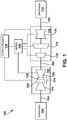
- FIG. 1 shows a schematic view of CCPP 100. It is emphasized that the teachings of the disclosure are applicable to any heat exchanger.
- CCPP 100 may include a gas turbine (GT) system 102 operably connected to a generator 104, and a steam turbine (ST) system 110 operably coupled to another generator 112.
- GT gas turbine
- ST steam turbine
- Generator 104 and GT system 102 may be mechanically coupled by a shaft 106, which may transfer energy between a drive shaft (not shown) of GT system 102 and generator 104.
- CCPP 100 is a single shaft system with two generators, but one with skill in the art will readily understand that the teachings of the disclosure are applicable to any variety of combined cycle power generating system.
- a heat exchanger 108 in accordance with embodiments of the disclosure is operably connected to GT system 102 and ST system 110.
- heat exchanger 108 may take the form of a heat recovery steam generator (HRSG).
- Heat exchanger 108 may be fluidly connected to both GT system 102 and ST system 110 via conventional conduits (numbering omitted).
- generators 104, 112 and shaft 106 may be of any size or type known in the art and may differ depending upon their application or the system to which they are connected. Common numbering of the generators and shafts is for clarity and does not necessarily suggest these generators or shafts are identical.
- GT system 102 may include a compressor 120 and a combustor 124.
- Combustor 124 includes a combustion region 126 and a fuel nozzle assembly 128.
- GT system 102 also includes a gas turbine 130 coupled to common compressor/turbine shaft 106.
- GT system 102 may be a MS7001FB engine, sometimes referred to as a 9FB engine, commercially available from General Electric Company, Greenville, S.C.
- the present disclosure is not limited to any one particular GT system and may be implanted in connection with other engines including, for example, the MS7001FA (7FA) and MS9001FA (9FA) engine models of General Electric Company.
- fuel such as a gas, e.g., natural gas
- a fluid e.g., oil
- gas turbine 130 the energy of the hot gases is converted into work, some of which is used to drive compressor 120 through rotating shaft 106, with the remainder available for useful work to drive a load such as generator 104 via shaft 106 for producing electricity.
- FIG. 1 also represents CCPP 100 in its simplest form in which the energy in the exhaust gases exiting gas turbine 130 are converted into additional useful work.
- the exhaust gases enter heat exchanger 108, in the form of an HRSG, in which water is converted to steam in the manner of a boiler.
- Heat exchanger 108 may also use the energy to create a hot feedwater, e.g., having temperature in the range of 95 °C to 99 °C.
- Heat exchanger 108 may take the form of a once-through, duct-fired HRSG, which indicates that combustion gases pass through the heat exchanger once and that supplemental heating of combustion gases may be provided, e.g., within ducts 109 through which combustion gases from GT system 102 pass to heat exchanger 108.
- the supplemental heated combustion gases are indicated as working fluid (or just "fluid") 142 herein.
- ST system 110 may include one or more steam turbines.
- ST system 110 may include a high pressure (HP) turbine 132, an intermediate pressure (IP) turbine 134 and a low pressure (LP) turbine 136, each of which are coupled to shaft 106.
- HP high pressure
- IP intermediate pressure
- LP low pressure
- Each steam turbine 132, 134, 136 includes a plurality of rotating blades (not shown) mechanically coupled to shaft 106.
- steam from heat exchanger 108 and perhaps other sources enters an inlet of HP turbine 132, IP turbine 134 and/or LP turbine 136, and is channeled to impart a force on blades thereof causing shaft 106 to rotate.
- steam from an upstream turbine may be employed later in a downstream turbine.
- the steam thus produced by heat exchanger 108 drives at least a part of ST system 110 in which additional work is extracted to drive shaft 106 and an additional load such as second generator 112, which, in turn, produces additional electric power.
- additional load such as second generator 112
- turbines 130, 132, 134, 136 drive a common generator.
- FIG. 1 also shows a CCPP control system 138 operatively coupled to the GT system 102, the HRSG 108, and the ST system 110.
- Control system 138 may include any now known or later developed computerized controller for providing automated control of CCPP 100.
- FIG. 2 shows a partially transparent, perspective view of an embodiment of heat exchanger 108.
- Heat exchanger 108 is illustrated as an HRSG configured to couple to GT system 102 ( FIG. 1 ) and to deliver steam to, e.g., ST system 110 ( FIG. 1 ), and/or heated water to other parts of CCPP 100 ( FIG. 1 ).
- heat exchanger 108 includes an insulated casing 140 (hereinafter "casing 140") configured to contain fluid 142.
- Casing 140 may be housed in an HRSG enclosure 148.
- Casing 140 may include any now known or later developed insulated duct configured to contain fluid 142, e.g., with a carbon steel or stainless steel inner liner, insulation layer and outer carbon steel layer.
- Fluid 142 may be any form of gas having a heat differential with a fluid 144 (shown by arrows only) passing through a plurality of heat exchange tubes 146 of heat exchanger 108.
- fluid 142 may include exhaust combustion gases from GT system 102, which may or may not be exposed to supplement heating in ducts 109 ( FIG. 1 ). Heat is exchanged between fluid 142 and fluid 144.
- Fluid 142 may be combustion gas exhaust from GT system 102 ( FIG. 1 ), and fluid 144 may be a liquid, e.g., water, and/or gas, e.g., steam. Fluid 142 passes over and around the exterior surfaces of a plurality of heat exchange tubes 146 and exits casing 140 via an exhaust system 150 ( FIG.
- Enclosure 148 may include any now known or later developed structural protection, e.g., a building or other physical protection.
- heat exchange tubes 146 extend in a vertical direction, and fluid 142 passes thereabout in a generally horizontal direction.
- "generally” as applied to a flow direction of fluid 142 indicates that the fluid usually travels in the stated direction with some minor or temporary deviations as it passes over or about tubes 146 that may impede its path.
- Tubes 146 may have any now known or later developed form of heat exchange tubes and may be made of any material capable of providing the desired heat transfer characteristics, flexibility, and ability to withstand the environment in which exposed. Tubes 146 may vary in size depending on application, e.g., in some applications varying from 1.25inches to 2.0 inches in outer diameter. In one embodiment, tubes 146 may take on any form as described in co-pending US Patent Application No. 16/230,736, filed December 14, 2018 , which is hereby incorporated by reference.
- FIG. 3 shows a perspective view of one embodiment of a finned tube from the noted application.
- tubes 146 may include a plurality of disks 152 disposed around a center tube 154 aligned in a longitudinal direction 156.
- Each disk 152 may be substantially planar and may be stacked such that it is disposed longitudinally above and/or below at least one adjacent disk 152.
- Center tube 154 may include any now known or later developed tubular member configured to allow fluid 144 to pass therethrough, e.g., by pumping or other force.
- Each disk 152 may include a plurality of fin segments 158 extending radially outward from a disk center portion 160. Disk center portion 160 extends circumferentially around the outer circumference of center tube 154.
- Each of fin segments 158 is separated from an adjacent fin segment 158 by a serration 162.
- Fin segments 158 of adjacent disks can be circumferentially and/or longitudinally aligned or circumferentially and/or longitudinally offset. Fin segments 158 may be arranged in a spiral configuration, an alternating pattern, and/or a random configuration relative to the fin segments 158 longitudinally above and/or below them.
- Disk(s) 152 may be at least partially composed of aluminum and/or other thermally conductive materials such as beryllium, copper, gold, magnesium, iridium, molybdenum, rhodium, silver, tungsten, and/or other suitable materials, as well as alloys thereof.
- Center tube 154 may be at least partially composed of carbon steel, alloy steel, stainless steel, ferritic stainless, austenitic stainless, and/or other materials that are sufficiently thermally conductive, stress tolerant, and temperature resistant.
- an HRSG may include center tubes 154 in the superheater and/or evaporate sections (not labeled) that are composed of materials that are resistant to higher temperatures (for example, 1100 °F).
- the HRSG may also include center tubes 154 in the economizer and/or evaporate sections (not labeled) that are composed of materials that have lower temperature resistance and higher thermal conductivity. While one example of a tube 146 has been described, it is understood that heat exchanger tubes can take a variety of alternative forms.
- FIG. 4 shows a schematic plan view of heat exchanger 108 including at least one at least one heat exchanger (HE) section 168 in casing 140, according to embodiments of the disclosure.
- Heat exchanger 108 may include any number of laterally adjacent HE sections 168 configured to span a substantial portion (e.g., most, if not all) of a working fluid path 164. Fluid 142 may flow along working fluid path 164. The size or width of working fluid path 164 and the number of HE sections 168 may vary depending on, for example, the size of heat exchanger 108, the type of fluid 142, and a number of other factors.
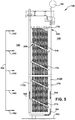
- FIG. 5 shows a schematic side view of one HE section 168
- FIG. 6 shows an enlarged, partial side view of a number of cross-supports 174, 176 and tube positioners 180 of an HE section 168, according to embodiments of the disclosure.
- Each HE section 168 may include a pair of spaced supports 170 (as shown in FIG. 4 ), with each support 170 including an upstream support 172U and a downstream support 172D.
- a first cross-support 174 couples to and extends between respective upstream and downstream supports 172U, 172D.
- heat exchanger 108 also may include at least one second cross-support 176 coupled to and extending between respective upstream and downstream supports 172U, 172D.
- each cross-support 174, 176 includes a plurality of tube positioners 180 suspended therefrom.
- Each tube positioner 180 positions a plurality of tubes 146 extending across at least a portion of working fluid path 164 through casing 140.
- tube positioners 180 create what may be referred to as 'tube sheets'.
- tube positioners 180 support tubes 146 to create a curvilinear or serpentine path through which fluid 142 passes to transfer heat between fluid 142 and fluid 144 passing through tubes 146.
- upstream support 172U and/or downstream support 172D may include a coolant carrying body 182 configured to direct a coolant 184 ( FIGS. 5 and 6 ) therethrough.
- Coolant carrying body 182 may include a tubular member 186 (e.g., a steel pipe) through which coolant 184 may pass.
- the exterior surface of tubular member 186 can be protected by any appropriate insulation 188 ( FIG. 6 only), e.g., a ceramic fiber blanket.
- Coolant 184 may include any fluid having a temperature lower than fluid 142 and may include water and/or a gas, like air.
- coolant 184 may include, for example, HP turbine 132 ( FIG. 1 ) economizer water; however, other options are also possible.
- tubular member 186 of each support 172U, 172D may be fluidly coupled so coolant 184 may circulate between the supports 172U, 172D. However, this is not necessary in all instances, as each support 172U, 172D may be independent of one another. In another example, coolant 184 may pass through only one of supports 172U, 172D.
- heat exchanger 108 may include an appropriate pumping system 190 ( FIG. 5 only) configured to pass coolant 184 through coolant carrying body(ies) 182. Coolant 184 cools upstream and downstream support(s) 172U, 172D and at least part of first cross-support 174 and, optionally, second cross-support(s) 176. Supports 172U, 172D may be fixed to any structure appropriate to support cross-supports 174, 176 and tube positioners 180, e.g., a floor 192 of enclosure 148.
- each first cross-support 174 is coupled to and extends between respective upstream and downstream supports 172U, 172D.
- First cross-supports 174 may be coupled to supports 172U, 172D in any manner, e.g., fasteners, welding, etc.
- cross-support 174 may extend through insulation 188 for direct thermal contact with tubular member 186.
- First cross-supports 174 may extend substantially horizontally between supports 172U, 172D at an uppermost end 194 of the respective upstream and downstream supports.
- Each first cross-support 174 may provide an uppermost cross-support of each HE section 168.
- Second cross-supports 176 may be coupled to and extend between upstream and downstream supports 172U, 172D below each first cross-support 174. That is, any number of vertically spaced second cross-supports 176 can be used to create any height of heat exchanger desired.
- Each second cross-support 176 is vertically distanced from an adjacent cross-support thereabove, i.e., either first cross-support 174 or another second cross-support 176.
- Each second cross-support 176 has an upstream end 200 coupled to upstream support 172U and a downstream end 202 coupled to downstream support 172D.
- Second cross-supports 176 may be coupled to supports 172U, 172D in any manner, e.g., fasteners, welding, etc. As shown in FIG.
- cross-supports 176 may extend through insulation 188 for direct thermal contact with tubular member 186.
- upstream end 200 of second cross-supports 176 is vertically higher than a respective downstream end 202 thereof, creating an attack angle ⁇ with working fluid path 164 for the respective second cross-supports.
- Attack angle ⁇ may be, for example, between approximately 20° to 40° relative to working fluid path 164, e.g., relative to horizontal.
- Heat exchange tubes 146 of heat exchanger 108 are positioned by a plurality of tube positioners 180 suspended from each cross-support 174, 176. Tube positioners 180 each position a plurality of heat exchange tubes 146 extending across at least a portion of working fluid path 164. As understood in the field, heat exchange tubes 146 run into and out of the page in FIGS. 5-6 and have U-shaped connectors 210 ( FIG. 4 ) coupling ends of pairs thereof to create a cooling circuit through which fluid 144 may flow. Fluid 144 may be transmitted through heat exchange tubes 146 in any now known or later developed fashion, e.g., pumping, expansion through gasification of liquid, etc.
- Tube positioners 180 may include plates of a ferritic material (e.g., steel) that are coupled to respective cross-supports 174, 176, e.g., by fasteners or welding. Each tube positioner 180 includes a plurality of spaced openings 206 with each opening 206 configured to position a respective heat exchange tube 146. Openings 206 may be arranged in any manner to foster the desired heat exchange between fluids 142, 144, e.g., they may be staggered to create a curved or serpentine working fluid path 164 through heat exchange tubes 146. For example, each tube positioner 180 may position a plurality of heat exchange tubes 146 in a vertical plane V (lower left in FIG. 6 ); however, vertical alignment may not be desired in all instances.
- V lower left in FIG. 6
- tube positioners 180 may be supported by a respective cross-support 174, 176 to create any desired depth of working fluid path 164 with heat exchange tubes 146. It is noted that tube positioners 180 are shown in a spaced manner for clarity in FIG. 6 ; they may be in relatively close proximity (less than an inch) as shown in FIG. 5 .
- tube positioners 180 supported by first cross-support 174 and all second cross-supports 176 except for a lowermost second cross-support 176L may have progressively longer lengths from an upstream-most tube positioner 212U to a downstream-most tube positioner 212D. That is, length L1 of upstream-most tube positioner 212U ⁇ L2 of adjacent tube positioner... ⁇ length Ln of downstream-most tube positioner 212D.
- tube positioners 180 may each have a lowermost end 214 angled to substantially match the attack angle ⁇ of second cross-support 176, if any, therebelow. In this fashion, thermal expansion of tube positioners 180 during operation will maintain a uniform spacing with respective adjacent second cross-supports 176.
- tube positioners 180 supported by lowermost second cross-support 176L may have progressively shorter lengths from an upstream-most tube positioner 216U to a downstream-most tube positioner 216D. That is, length L3 of upstream-most tube positioner 216U > length L4 of adjacent tube positioner... > length Lm of downstream-most tube positioner 216D.
- Each support 172, cross-support 174, 176, and tube positioner 180 can be made of any material capable of withstanding the environment within heat exchanger 108.
- use of cooled supports 172 and the distribution of the load of heat exchange tubes 146 amongst a number of vertically spaced cross-supports 174, 176 allow use of a ferritic material (such as steel) for supports 172, cross-supports 174, 176, and tube positioners 180, even where supplemental heating is provided.
- This arrangement reduces costs and manufacturing complexity and allows use of ferritic material rather than more costly and hard-to-manufacture, high-grade material in, for example, a once-through, duct-fired HRSG.
- heat exchanger 108 may also optionally include a heat exchange tube positioning member 220 (hereinafter "positioning member 220") on an upper surface 222 of at least one second cross-support 176.
- Positioning member(s) 220 may include a seat 224 for positioning a plurality of lowermost heat exchange tubes 146 supported by a vertically-above cross-support 174 or 176. Any number of seats 224 may be provided. Seats 224 are sized and shaped to receive heat exchange tubes 146 without damaging the tubes, e.g., to receive an outer diameter of disks 152 ( FIG. 3 ).
- positioning members 220 may assist in retaining lateral positioning of the positioners and their respective heat exchange tubes 146. While a number of positioning members 220 are shown, they may be provided as single member extending along upper surface 222 of a respective cross-support 176, e.g., creating a one-piece scalloped positioning member.
- tube positioners 180 are shown with a single column of vertically spaced pairs of heat exchange tubes 146. Due to the cooling and distribution of load provided by embodiments of the disclosure, in other embodiments as shown in FIG. 7 , more than one vertical column of spaced pairs of heat exchange tubes 146 may be provided on a particular tube positioner 280. Providing more than a single column of vertically spaced pairs of heat exchange tubes 146 on each tube positioner 280 can reduce the number of tube positioners required and, hence, the manufacturing time and costs to create a heat exchanger 108. As also shown in FIG.
- each cross-support 174, 176 is coupled to respective upstream and downstream supports 172U, 172D at a location outside a periphery of the plurality of heat exchange tubes 146, which makes manufacturing heat exchanger easier, less time consuming and less expensive compared to conventional heat exchangers.
- tube positioners to support heat exchange tubes 146 and the use of cooling support(s) 172 provides a number of advantages compared to conventional heat exchangers. For example, the distribution of the load to a number of vertically spaced cross-supports makes manufacturing a heat exchanger easier, less time consuming and less expensive compared to conventional heat exchangers. Further, any thermal growth experienced during operation is separated by each cross-support and does not extend top to bottom of the tube sheets, as in conventional heat exchangers. As a result, ferritic material can be used rather than austenitic or other high-grade material, such as Inconel. Supports 172, cross-supports 174, 176, and tube positioners 180 can all be made of a ferritic material, reducing costs and manufacturing complexity.
- heat exchanger 108 can be used with a duct-fired HRSG that runs with hotter gases on legacy HRSGs that have horizontal flow. Heat exchanger 108 can also be used in a wide variety of applications outside of an HRSG.
- Approximating language may be applied to modify any quantitative representation that could permissibly vary without resulting in a change in the basic function to which it is related. Accordingly, a value modified by a term or terms, such as “about,” “approximately” and “substantially,” are not to be limited to the precise value specified. In at least some instances, the approximating language may correspond to the precision of an instrument for measuring the value.
- range limitations may be combined and/or interchanged. Such ranges are identified and include all the sub-ranges contained therein unless context or language indicates otherwise. "Approximately” as applied to a particular value of a range applies to both values, and unless otherwise dependent on the precision of the instrument measuring the value, may indicate +/- 10% of the stated value(s).
Landscapes
- Engineering & Computer Science (AREA)
- General Engineering & Computer Science (AREA)
- Mechanical Engineering (AREA)
- Physics & Mathematics (AREA)
- Thermal Sciences (AREA)
- Chemical & Material Sciences (AREA)
- Combustion & Propulsion (AREA)
- Heat-Exchange Devices With Radiators And Conduit Assemblies (AREA)
- Geometry (AREA)
Abstract
Description
- The disclosure relates generally to heat exchangers and, more particularly, to a heat exchanger with multiple cooled supports for heat exchange tubes, and a once-through, duct-fired heat recovery steam generator that uses the heat exchanger.
- Heat exchangers are used in a wide variety of industrial machines. In combined cycle power plants (CCPPs), for example, a heat exchanger in the form of a heat recovery steam generator (HRSG) converts heat from the exhaust of a gas turbine (GT) system to create steam for a steam turbine system and/or hot water for cogeneration equipment. HRSGs provide heat exchange tubes through which water and/or steam pass to be heated by the passing exhaust gases. The heat exchange tubes are formed into an array using a number of tube positioners that are supported within a casing, e.g., from the headers, manifolds, etc. The tube positioners position the tubes into tube sheets. The tube positioners are coupled such that each tube support supports the respective tube support below. Hence, a tube positioner near the top of the configuration carries more load than one near the bottom. In conventional once-through HRSGs, the tube supports are typically made of a ferritic material.
- It is oftentimes desirable to further heat the working fluid passing through a heat exchanger. For example, the exhaust gases from the GT system may be heated prior to entry into a once-through HRSG to improve the efficiency of the HRSG and the CCPP. The heating may be referred to as 'supplementary heating,' or the HRSG may be referred to as 'once-through, duct-fired HRSG', because the heating occurs in a duct between the output of the GT system and the HRSG.
- The supplemental heating presents a number of challenges for current once-through HRSGs. For example, the increased heat level increases the temperature and the corrosiveness of the gas flow such that the typically-used ferritic material (e.g., steel) may not withstand the environment for the desired lifespan. To address this issue, the ferritic material must be hardened against the harsher environment at greatly increased costs. Alternately, higher grade or austenitic material (such as Inconel alloys) may be used to attain the desired lifespans. Unfortunately, the additional material cost and increased manufacturing complexity eliminates the value added from the increased efficiency of the supplemental heating for a once-through HRSG.
- In addition to corrosion challenges, in common vertically oriented HRSGs, different tube supports may experience different thermal and mechanical stresses. For example, the upstream ends of the upper tube supports experience high load and high temperatures that may shorten lifespan. No cooling is provided in current arrangements.
- A first aspect of the disclosure provides a heat exchanger, comprising: a casing configured to direct a working fluid therethrough; at least one heat exchanger (HE) section in the casing, each HE section including a pair of spaced supports, each spaced support including: an upstream support and a downstream support, wherein at least one of the upstream support and the downstream support includes a coolant carrying body configured to direct a coolant therethrough; a first cross-support coupled to and extending between respective upstream and downstream supports; at least one second cross-support coupled to and extending between the respective upstream and downstream supports, each second cross-support of the at least one second cross-support vertically distanced from an adjacent cross-support thereabove; and a plurality of tube positioners suspended from each cross-support, each tube positioner positioning a plurality of heat exchange tubes extending across at least a portion of a working fluid path through the casing.
- A second aspect of the disclosure provides a once-through, duct-fired heat recovery steam generator (HRSG) of a combined cycle power plant, the once-through HRSG comprising: a casing configured to direct a working fluid therethrough; a plurality of laterally adjacent heat exchanger (HE) sections configured to span a substantial portion of the working fluid path, each HE section including a pair of spaced supports, each spaced support including: an upstream support and a downstream support, wherein at least one of the upstream support and the downstream support includes a coolant carrying body configured to direct a coolant therethrough; a first cross-support coupled to and extending between respective upstream and downstream supports; at least one second cross-support coupled to and extending between the respective upstream and downstream supports, each second cross-support of the at least one second cross-support vertically distanced from an adjacent cross-support thereabove; and a plurality of tube positioners suspended from each cross-support, each tube positioner positioning a plurality of heat exchange tubes extending across at least a portion of a working fluid path through the casing, wherein each tube positioner positions a plurality of heat exchange tubes in a vertical plane, and wherein each pair of spaced supports, the cross-supports, and the plurality of tube positioners are made of a ferritic material.
- The illustrative aspects of the present disclosure are designed to solve the problems herein described and/or other problems not discussed.
- These and other features of this disclosure will be more readily understood from the following detailed description of the various aspects of the disclosure taken in conjunction with the accompanying drawings that depict various embodiments of the disclosure, in which:
-
FIG. 1 shows a schematic view of an illustrative combined cycle power plant for a heat exchanger, according to embodiments of the disclosure; -
FIG. 2 shows a partially transparent perspective view of a heat exchanger in the form of a heat recovery steam generator with vertical heat exchange tubes, according to one embodiment of the disclosure; -
FIG. 3 shows a perspective view of an illustrative heat exchange tube; -
FIG. 4 shows a schematic plan view of a plurality of heat exchange sections in a heat exchanger, according to embodiments of the disclosure; -
FIG. 5 shows schematic side view of a heat exchange section fromFIG. 4 , according to embodiments of the disclosure; -
FIG. 6 shows an enlarged side view of a portion of a heat exchange section including cross-supports and tube positioners, according to embodiments of the disclosure; and -
FIG. 7 shows a side view of a tube positioner including more than one column of vertically spaced pairs of heat exchange tubes, according to alternative embodiments of the disclosure. - It is noted that the drawings of the disclosure are not necessarily to scale. The drawings are intended to depict only typical aspects of the disclosure and therefore should not be considered as limiting the scope of the disclosure. In the drawings, like numbering represents like elements between the drawings.
- As an initial matter, in order to clearly describe the current technology, it will become necessary to select certain terminology when referring to and describing components within an illustrative application in the form of a combined cycle power plant and parts thereof. To the extent possible, common industry terminology will be used and employed in a manner consistent with its accepted meaning. Unless otherwise stated, such terminology should be given a broad interpretation consistent with the context of the present application and the scope of the appended claims. Those of ordinary skill in the art will appreciate that often a particular component may be referred to using several different or overlapping terms. What may be described herein as being a single part may include and be referenced in another context as consisting of multiple components. Alternatively, what may be described herein as including multiple components may be referred to elsewhere as a single part.
- In addition, several descriptive terms may be used regularly herein, and it should prove helpful to define these terms at the onset of this section. These terms and their definitions, unless stated otherwise, are as follows. As used herein, "downstream" and "upstream" are terms that indicate a direction relative to the flow of a fluid, such as a working fluid through the turbine engine or, for example, the flow of hot gas through a heat exchanger. The term "downstream" corresponds to the direction of flow of the fluid, and the term "upstream" refers to the direction opposite to the flow. The terms "forward" and "aft," without any further specificity, refer to directions, with "forward" referring to the front or compressor end of the engine, and "aft" referring to the rearward or turbine end of the engine.
- It is often required to describe parts that are located at differing radial positions with regard to a center axis. The term "radial" refers to movement or position perpendicular to an axis. In cases such as this, if a first component resides closer to the axis than a second component, it will be stated herein that the first component is "radially inward" or "inboard" of the second component. If, on the other hand, the first component resides further from the axis than the second component, it may be stated herein that the first component is "radially outward" or "outboard" of the second component. The term "axial" refers to movement or position parallel to an axis. Finally, the term "circumferential" refers to movement or position around an axis. It will be appreciated that such terms may be applied in relation to the center axis of the turbine.
- In addition, several descriptive terms may be used regularly herein, as described below. The terms "first", "second", and "third" may be used interchangeably to distinguish one component from another and are not intended to signify location or importance of the individual components.
- The terminology used herein is for the purpose of describing particular embodiments only and is not intended to be limiting of the disclosure. As used herein, the singular forms "a", "an" and "the" are intended to include the plural forms as well, unless the context clearly indicates otherwise. It will be further understood that the terms "comprises" and/or "comprising," when used in this specification, specify the presence of stated features, integers, steps, operations, elements, and/or components, but do not preclude the presence or addition of one or more other features, integers, steps, operations, elements, components, and/or groups thereof. "Optional" or "optionally" means that the subsequently described event or circumstance may or may not occur, and that the description includes instances where the event occurs and instances where it does not.
- Where an element or layer is referred to as being "on," "engaged to," "connected to" or "coupled to" another element or layer, it may be directly on, engaged, connected or coupled to the other element or layer, or intervening elements or layers may be present. In contrast, when an element is referred to as being "directly on," "directly engaged to," "directly connected to" or "directly coupled to" another element or layer, there may be no intervening elements or layers present. Other words used to describe the relationship between elements should be interpreted in a like fashion (e.g., "between" versus "directly between," "adjacent" versus "directly adjacent," etc.). As used herein, the term "and/or" includes any and all combinations of one or more of the associated listed items.
- As indicated above, the disclosure provides a heat exchanger with multiple cooled supports for heat exchange tubes. The heat exchanger includes a casing configured to direct a working fluid therethrough. At least one heat exchanger (HE) section is in the casing. Each HE section includes a pair of spaced supports, including an upstream support and a downstream support. At least one of the upstream support and the downstream support includes a coolant carrying body configured to direct a coolant therethrough. A first cross-support is coupled to and extends between respective upstream and downstream supports. In contrast to conventional heat exchangers that have the one cross-support carry the load of each vertically oriented heat exchange tube sheet, embodiments of the disclosure provide at least one second cross-support coupled to and extending between the respective upstream and downstream supports. Each second cross-support is vertically distanced from an adjacent cross-support thereabove.
- A plurality of tube positioners, e.g., tube sheets, are suspended from each cross-support, thus distributing the load of the heat exchange tubes over a number of cross-supports. Each tube positioner positions a plurality of heat exchange tubes extending across at least a portion of a working fluid path through the casing. Each cross-support carries some portion of the vertical load of the tube positioners, rather than a single cross-support bearing the entire load. Any thermal expansion that would normally damage a conventional arrangement exposed to supplemental heating is spread through the different segments and is limited by the cooling of the spaced supports. Hence, the segmentation of the supports for the vertically arranged tube positioners with the cooled, spaced supports allows the heat exchanger to be used in the hotter environments of a once-through, duct-fired HRSG.
- Turning to
FIG. 1 , a heat exchanger according to embodiments of the disclosure will be described relative to an illustrative application in the form of a combined cycle power plant (CCPP) 100.FIG. 1 shows a schematic view ofCCPP 100. It is emphasized that the teachings of the disclosure are applicable to any heat exchanger.CCPP 100 may include a gas turbine (GT)system 102 operably connected to agenerator 104, and a steam turbine (ST)system 110 operably coupled to anothergenerator 112.Generator 104 andGT system 102 may be mechanically coupled by ashaft 106, which may transfer energy between a drive shaft (not shown) ofGT system 102 andgenerator 104. In the illustrative application,CCPP 100 is a single shaft system with two generators, but one with skill in the art will readily understand that the teachings of the disclosure are applicable to any variety of combined cycle power generating system. - Also shown in
FIG. 1 , aheat exchanger 108 in accordance with embodiments of the disclosure is operably connected toGT system 102 andST system 110. As will be described in greater detail herein,heat exchanger 108 may take the form of a heat recovery steam generator (HRSG).Heat exchanger 108 may be fluidly connected to bothGT system 102 andST system 110 via conventional conduits (numbering omitted). - It is understood that
generators shaft 106 may be of any size or type known in the art and may differ depending upon their application or the system to which they are connected. Common numbering of the generators and shafts is for clarity and does not necessarily suggest these generators or shafts are identical. -
GT system 102 may include acompressor 120 and acombustor 124.Combustor 124 includes acombustion region 126 and afuel nozzle assembly 128.GT system 102 also includes agas turbine 130 coupled to common compressor/turbine shaft 106. In one embodiment,GT system 102 may be a MS7001FB engine, sometimes referred to as a 9FB engine, commercially available from General Electric Company, Greenville, S.C. The present disclosure is not limited to any one particular GT system and may be implanted in connection with other engines including, for example, the MS7001FA (7FA) and MS9001FA (9FA) engine models of General Electric Company. - In operation, air enters the inlet of
compressor 120, is compressed and then discharged to combustor 124 where fuel, such as a gas, e.g., natural gas, or a fluid, e.g., oil, is burned to provide high energy combustion gases which drivegas turbine 130. Ingas turbine 130, the energy of the hot gases is converted into work, some of which is used to drivecompressor 120 throughrotating shaft 106, with the remainder available for useful work to drive a load such asgenerator 104 viashaft 106 for producing electricity. -
FIG. 1 also representsCCPP 100 in its simplest form in which the energy in the exhaust gases exitinggas turbine 130 are converted into additional useful work. The exhaust gases enterheat exchanger 108, in the form of an HRSG, in which water is converted to steam in the manner of a boiler.Heat exchanger 108 may also use the energy to create a hot feedwater, e.g., having temperature in the range of 95 °C to 99 °C. -
Heat exchanger 108 may take the form of a once-through, duct-fired HRSG, which indicates that combustion gases pass through the heat exchanger once and that supplemental heating of combustion gases may be provided, e.g., within ducts 109 through which combustion gases fromGT system 102 pass toheat exchanger 108. The supplemental heated combustion gases are indicated as working fluid (or just "fluid") 142 herein. -
ST system 110 may include one or more steam turbines. For example,ST system 110 may include a high pressure (HP)turbine 132, an intermediate pressure (IP)turbine 134 and a low pressure (LP)turbine 136, each of which are coupled toshaft 106. Eachsteam turbine shaft 106. In operation, steam fromheat exchanger 108 and perhaps other sources, enters an inlet ofHP turbine 132,IP turbine 134 and/orLP turbine 136, and is channeled to impart a force on blades thereof causingshaft 106 to rotate. As understood, steam from an upstream turbine may be employed later in a downstream turbine. The steam thus produced byheat exchanger 108 drives at least a part ofST system 110 in which additional work is extracted to driveshaft 106 and an additional load such assecond generator 112, which, in turn, produces additional electric power. In some configurations,turbines -
FIG. 1 also shows aCCPP control system 138 operatively coupled to theGT system 102, theHRSG 108, and theST system 110.Control system 138 may include any now known or later developed computerized controller for providing automated control ofCCPP 100. -
FIG. 2 shows a partially transparent, perspective view of an embodiment ofheat exchanger 108.Heat exchanger 108 is illustrated as an HRSG configured to couple to GT system 102 (FIG. 1 ) and to deliver steam to, e.g., ST system 110 (FIG. 1 ), and/or heated water to other parts of CCPP 100 (FIG. 1 ). As illustrated,heat exchanger 108 includes an insulated casing 140 (hereinafter "casing 140") configured to containfluid 142. Casing 140 may be housed in anHRSG enclosure 148. Casing 140 may include any now known or later developed insulated duct configured to contain fluid 142, e.g., with a carbon steel or stainless steel inner liner, insulation layer and outer carbon steel layer. -
Fluid 142 may be any form of gas having a heat differential with a fluid 144 (shown by arrows only) passing through a plurality ofheat exchange tubes 146 ofheat exchanger 108. As noted, fluid 142 may include exhaust combustion gases fromGT system 102, which may or may not be exposed to supplement heating in ducts 109 (FIG. 1 ). Heat is exchanged betweenfluid 142 andfluid 144.Fluid 142 may be combustion gas exhaust from GT system 102 (FIG. 1 ), andfluid 144 may be a liquid, e.g., water, and/or gas, e.g., steam. Fluid 142 passes over and around the exterior surfaces of a plurality ofheat exchange tubes 146 and exits casing 140 via an exhaust system 150 (FIG. 2 ), e.g., a stack and/or scrubber, etc., while fluid 144 passes through the interior of the plurality ofheat exchange tubes 146.Enclosure 148 may include any now known or later developed structural protection, e.g., a building or other physical protection. - In the example of
FIGS. 2 and4-6 , heat exchange tubes 146 (hereinafter "tubes 146") extend in a vertical direction, and fluid 142 passes thereabout in a generally horizontal direction. As used herein, "generally" as applied to a flow direction offluid 142 indicates that the fluid usually travels in the stated direction with some minor or temporary deviations as it passes over or abouttubes 146 that may impede its path. -
Tubes 146 may have any now known or later developed form of heat exchange tubes and may be made of any material capable of providing the desired heat transfer characteristics, flexibility, and ability to withstand the environment in which exposed.Tubes 146 may vary in size depending on application, e.g., in some applications varying from 1.25inches to 2.0 inches in outer diameter. In one embodiment,tubes 146 may take on any form as described in co-pendingUS Patent Application No. 16/230,736, filed December 14, 2018 -
FIG. 3 shows a perspective view of one embodiment of a finned tube from the noted application. As illustrated,tubes 146 may include a plurality ofdisks 152 disposed around acenter tube 154 aligned in alongitudinal direction 156. Eachdisk 152 may be substantially planar and may be stacked such that it is disposed longitudinally above and/or below at least oneadjacent disk 152.Center tube 154 may include any now known or later developed tubular member configured to allow fluid 144 to pass therethrough, e.g., by pumping or other force. Eachdisk 152 may include a plurality offin segments 158 extending radially outward from adisk center portion 160.Disk center portion 160 extends circumferentially around the outer circumference ofcenter tube 154. Each offin segments 158 is separated from anadjacent fin segment 158 by a serration 162.Fin segments 158 of adjacent disks can be circumferentially and/or longitudinally aligned or circumferentially and/or longitudinally offset.Fin segments 158 may be arranged in a spiral configuration, an alternating pattern, and/or a random configuration relative to thefin segments 158 longitudinally above and/or below them. - Disk(s) 152 may be at least partially composed of aluminum and/or other thermally conductive materials such as beryllium, copper, gold, magnesium, iridium, molybdenum, rhodium, silver, tungsten, and/or other suitable materials, as well as alloys thereof.
Center tube 154 may be at least partially composed of carbon steel, alloy steel, stainless steel, ferritic stainless, austenitic stainless, and/or other materials that are sufficiently thermally conductive, stress tolerant, and temperature resistant. - In some embodiments, an HRSG may include
center tubes 154 in the superheater and/or evaporate sections (not labeled) that are composed of materials that are resistant to higher temperatures (for example, 1100 °F). The HRSG may also includecenter tubes 154 in the economizer and/or evaporate sections (not labeled) that are composed of materials that have lower temperature resistance and higher thermal conductivity. While one example of atube 146 has been described, it is understood that heat exchanger tubes can take a variety of alternative forms. -
FIG. 4 shows a schematic plan view ofheat exchanger 108 including at least one at least one heat exchanger (HE)section 168 incasing 140, according to embodiments of the disclosure.Heat exchanger 108 may include any number of laterallyadjacent HE sections 168 configured to span a substantial portion (e.g., most, if not all) of a workingfluid path 164.Fluid 142 may flow along workingfluid path 164. The size or width of workingfluid path 164 and the number ofHE sections 168 may vary depending on, for example, the size ofheat exchanger 108, the type offluid 142, and a number of other factors. -
FIG. 5 shows a schematic side view of oneHE section 168, andFIG. 6 shows an enlarged, partial side view of a number ofcross-supports tube positioners 180 of anHE section 168, according to embodiments of the disclosure. EachHE section 168 may include a pair of spaced supports 170 (as shown inFIG. 4 ), with eachsupport 170 including anupstream support 172U and adownstream support 172D. A first cross-support 174 couples to and extends between respective upstream anddownstream supports heat exchanger 108 also may include at least onesecond cross-support 176 coupled to and extending between respective upstream anddownstream supports - As will be further described, each cross-support 174, 176 includes a plurality of
tube positioners 180 suspended therefrom. Eachtube positioner 180 positions a plurality oftubes 146 extending across at least a portion of workingfluid path 164 throughcasing 140. Thus,tube positioners 180 create what may be referred to as 'tube sheets'. Collectively,tube positioners 180support tubes 146 to create a curvilinear or serpentine path through which fluid 142 passes to transfer heat betweenfluid 142 and fluid 144 passing throughtubes 146. - As shown in
FIGS. 4-6 ,upstream support 172U and/ordownstream support 172D may include a coolant carrying body 182 configured to direct a coolant 184 (FIGS. 5 and6 ) therethrough. Coolant carrying body 182 may include a tubular member 186 (e.g., a steel pipe) through whichcoolant 184 may pass. The exterior surface of tubular member 186 can be protected by any appropriate insulation 188 (FIG. 6 only), e.g., a ceramic fiber blanket.Coolant 184 may include any fluid having a temperature lower thanfluid 142 and may include water and/or a gas, like air. In the illustrative once-through, duct-fired HRSG application,coolant 184 may include, for example, HP turbine 132 (FIG. 1 ) economizer water; however, other options are also possible. - As shown in
FIG. 5 , in one example, tubular member 186 of eachsupport coolant 184 may circulate between thesupports support coolant 184 may pass through only one ofsupports heat exchanger 108 may include an appropriate pumping system 190 (FIG. 5 only) configured to passcoolant 184 through coolant carrying body(ies) 182.Coolant 184 cools upstream and downstream support(s) 172U, 172D and at least part offirst cross-support 174 and, optionally, second cross-support(s) 176.Supports cross-supports tube positioners 180, e.g., afloor 192 ofenclosure 148. - As shown best in
FIGS. 5 and6 , eachfirst cross-support 174 is coupled to and extends between respective upstream anddownstream supports First cross-supports 174 may be coupled tosupports FIG. 6 , cross-support 174 may extend throughinsulation 188 for direct thermal contact with tubular member 186.First cross-supports 174 may extend substantially horizontally betweensupports uppermost end 194 of the respective upstream and downstream supports. Eachfirst cross-support 174 may provide an uppermost cross-support of eachHE section 168. - Any number of
second cross-supports 176 may be coupled to and extend between upstream anddownstream supports first cross-support 174. That is, any number of vertically spacedsecond cross-supports 176 can be used to create any height of heat exchanger desired. Eachsecond cross-support 176 is vertically distanced from an adjacent cross-support thereabove, i.e., either first cross-support 174 or anothersecond cross-support 176. Eachsecond cross-support 176 has anupstream end 200 coupled toupstream support 172U and adownstream end 202 coupled todownstream support 172D.Second cross-supports 176 may be coupled tosupports FIG. 6 , cross-supports 176 may extend throughinsulation 188 for direct thermal contact with tubular member 186. In contrast tofirst cross-supports 174,upstream end 200 ofsecond cross-supports 176 is vertically higher than a respectivedownstream end 202 thereof, creating an attack angle α with workingfluid path 164 for the respective second cross-supports. Attack angle α may be, for example, between approximately 20° to 40° relative to workingfluid path 164, e.g., relative to horizontal. -
Heat exchange tubes 146 ofheat exchanger 108 are positioned by a plurality oftube positioners 180 suspended from each cross-support 174, 176.Tube positioners 180 each position a plurality ofheat exchange tubes 146 extending across at least a portion of workingfluid path 164. As understood in the field,heat exchange tubes 146 run into and out of the page inFIGS. 5-6 and have U-shaped connectors 210 (FIG. 4 ) coupling ends of pairs thereof to create a cooling circuit through whichfluid 144 may flow.Fluid 144 may be transmitted throughheat exchange tubes 146 in any now known or later developed fashion, e.g., pumping, expansion through gasification of liquid, etc. -
Tube positioners 180 may include plates of a ferritic material (e.g., steel) that are coupled torespective cross-supports tube positioner 180 includes a plurality of spacedopenings 206 with each opening 206 configured to position a respectiveheat exchange tube 146.Openings 206 may be arranged in any manner to foster the desired heat exchange betweenfluids fluid path 164 throughheat exchange tubes 146. For example, eachtube positioner 180 may position a plurality ofheat exchange tubes 146 in a vertical plane V (lower left inFIG. 6 ); however, vertical alignment may not be desired in all instances. - Any number of
tube positioners 180 may be supported by arespective cross-support fluid path 164 withheat exchange tubes 146. It is noted thattube positioners 180 are shown in a spaced manner for clarity inFIG. 6 ; they may be in relatively close proximity (less than an inch) as shown inFIG. 5 . - As shown in
FIG. 6 , to accommodate the attack angle ofsecond cross-supports 176,tube positioners 180 supported byfirst cross-support 174 and allsecond cross-supports 176 except for a lowermost second cross-support 176L may have progressively longer lengths from an upstream-most tube positioner 212U to a downstream-most tube positioner 212D. That is, length L1 of upstream-most tube positioner 212U < L2 of adjacent tube positioner... < length Ln of downstream-most tube positioner 212D. - In addition,
tube positioners 180 may each have alowermost end 214 angled to substantially match the attack angle α ofsecond cross-support 176, if any, therebelow. In this fashion, thermal expansion oftube positioners 180 during operation will maintain a uniform spacing with respective adjacentsecond cross-supports 176. In order to accommodate the attack angle of a lowermost second cross-support 176L and provideheat exchange tubes 146 in a uniform fashion with the rest ofheat exchanger 108,tube positioners 180 supported by lowermost second cross-support 176L may have progressively shorter lengths from an upstream-most tube positioner 216U to a downstream-most tube positioner 216D. That is, length L3 of upstream-most tube positioner 216U > length L4 of adjacent tube positioner... > length Lm of downstream-most tube positioner 216D. - Each
support 172, cross-support 174, 176, andtube positioner 180 can be made of any material capable of withstanding the environment withinheat exchanger 108. However, use of cooledsupports 172 and the distribution of the load ofheat exchange tubes 146 amongst a number of vertically spaced cross-supports 174, 176 allow use of a ferritic material (such as steel) forsupports 172, cross-supports 174, 176, andtube positioners 180, even where supplemental heating is provided. This arrangement reduces costs and manufacturing complexity and allows use of ferritic material rather than more costly and hard-to-manufacture, high-grade material in, for example, a once-through, duct-fired HRSG. - As shown in
FIG. 6 ,heat exchanger 108 may also optionally include a heat exchange tube positioning member 220 (hereinafter "positioningmember 220") on anupper surface 222 of at least onesecond cross-support 176. Positioning member(s) 220 may include aseat 224 for positioning a plurality of lowermostheat exchange tubes 146 supported by a vertically-above cross-support seats 224 may be provided.Seats 224 are sized and shaped to receiveheat exchange tubes 146 without damaging the tubes, e.g., to receive an outer diameter of disks 152 (FIG. 3 ). In this fashion, as thermal expansion causestube positioners 180 to expand, positioningmembers 220 may assist in retaining lateral positioning of the positioners and their respectiveheat exchange tubes 146. While a number ofpositioning members 220 are shown, they may be provided as single member extending alongupper surface 222 of arespective cross-support 176, e.g., creating a one-piece scalloped positioning member. - Referring to
FIG. 6 ,tube positioners 180 are shown with a single column of vertically spaced pairs ofheat exchange tubes 146. Due to the cooling and distribution of load provided by embodiments of the disclosure, in other embodiments as shown inFIG. 7 , more than one vertical column of spaced pairs ofheat exchange tubes 146 may be provided on aparticular tube positioner 280. Providing more than a single column of vertically spaced pairs ofheat exchange tubes 146 on eachtube positioner 280 can reduce the number of tube positioners required and, hence, the manufacturing time and costs to create aheat exchanger 108. As also shown inFIG. 6 , each cross-support 174, 176 is coupled to respective upstream anddownstream supports heat exchange tubes 146, which makes manufacturing heat exchanger easier, less time consuming and less expensive compared to conventional heat exchangers. - Use of tube positioners to support
heat exchange tubes 146 and the use of cooling support(s) 172 provides a number of advantages compared to conventional heat exchangers. For example, the distribution of the load to a number of vertically spaced cross-supports makes manufacturing a heat exchanger easier, less time consuming and less expensive compared to conventional heat exchangers. Further, any thermal growth experienced during operation is separated by each cross-support and does not extend top to bottom of the tube sheets, as in conventional heat exchangers. As a result, ferritic material can be used rather than austenitic or other high-grade material, such as Inconel.Supports 172, cross-supports 174, 176, andtube positioners 180 can all be made of a ferritic material, reducing costs and manufacturing complexity. Placing moreheat exchange tubes 146 on eachtube positioner 280, as shown inFIG. 7 , can also reduce manufacturing time, complexity and costs. Collectively, the distribution of the load to a number of vertically spaced cross-supports and the cooling ofsupports 172 andcross-supports heat exchanger 108 tohotter temperature fluid 142, e.g., those with supplemental heating like a once-through, duct-fired HRSG in CCPP 100 (FIG. 1 ). Thus,heat exchanger 108 can be used with a duct-fired HRSG that runs with hotter gases on legacy HRSGs that have horizontal flow.Heat exchanger 108 can also be used in a wide variety of applications outside of an HRSG. - Approximating language, as used herein throughout the specification and claims, may be applied to modify any quantitative representation that could permissibly vary without resulting in a change in the basic function to which it is related. Accordingly, a value modified by a term or terms, such as "about," "approximately" and "substantially," are not to be limited to the precise value specified. In at least some instances, the approximating language may correspond to the precision of an instrument for measuring the value. Here and throughout the specification and claims, range limitations may be combined and/or interchanged. Such ranges are identified and include all the sub-ranges contained therein unless context or language indicates otherwise. "Approximately" as applied to a particular value of a range applies to both values, and unless otherwise dependent on the precision of the instrument measuring the value, may indicate +/- 10% of the stated value(s).
- The corresponding structures, materials, acts, and equivalents of all means or step plus function elements in the claims below are intended to include any structure, material, or act for performing the function in combination with other claimed elements as specifically claimed. The description of the present disclosure has been presented for purposes of illustration and description but is not intended to be exhaustive or limited to the disclosure in the form disclosed. Many modifications and variations will be apparent to those of ordinary skill in the art without departing from the scope and spirit of the disclosure. The embodiment was chosen and described in order to best explain the principles of the disclosure and the practical application and to enable others of ordinary skill in the art to understand the disclosure for various embodiments with various modifications as are suited to the particular use contemplated.
Claims (10)
- A heat exchanger (108), comprising:a casing (140) configured to direct a working fluid (142, 144) therethrough;at least one heat exchanger (HE) section (168) in the casing (140), each HE section (168) including a pair of spaced supports (170), each spaced support (170) including:an upstream support (172U) and a downstream support (172D), wherein at least one of the upstream support (172U) and the downstream support (172D) includes a coolant (184) carrying body configured to direct a coolant (184) therethrough;a first cross-support (174) coupled to and extending between respective upstream and downstream supports (172U, 172D);at least one second cross-support (176) coupled to and extending between the respective upstream and downstream supports (172U, 172D), each second cross-support (176) vertically distanced from an adjacent cross-support (174) thereabove; anda plurality of tube positioners (180) suspended from each cross-support (174), each tube positioner (180) positioning a plurality of heat exchange tubes (146) extending across at least a portion of a working fluid (142, 144) path through the casing (140).
- The heat exchanger (108) of claim 1, further comprising a pumping system configured to pass the coolant (184) through each coolant carrying body (182), wherein the coolant (184) cools the at least one of the upstream and downstream supports (172U, 172D) and at least part of at last one of the first and second cross-supports (174, 176).
- The heat exchanger (108) of claim 1, wherein each first cross-support (174) extends substantially horizontal between respective upstream and the downstream supports (172U, 172D) at an uppermost end (194, 200) of the respective upstream and downstream supports (172U, 172D).
- The heat exchanger (108) of claim 1, wherein each second cross-support (176) has an upstream end (194, 200) coupled to the upstream support (172U) and a downstream end (202) coupled to the downstream support (172D), wherein the upstream end (194, 200) is vertically higher than the downstream end (202), creating an attack angle with the working fluid path (164) for the respective second cross-support (176).
- The heat exchanger (108) of claim 4, wherein each tube positioner (180) positions a plurality of heat exchange tubes (146) in a vertical plane.
- The heat exchanger (108) of claim 4, wherein the plurality of tube positioners (180) supported by the first cross-support (174) and all second cross-supports (176) except for a lowermost second cross-support (176L) have progressively longer lengths from an upstream-most tube positioner (1212U, 216U) to a downstream-most tube positioner (180D, 212D, 216D).
- The heat exchanger (108) of claim 6, wherein the plurality of tube positioners (180) each have a lowermost end (214) an angled to substantially match the attack angle of the second cross-support (176) therebelow.
- The heat exchanger (108) of claim 6, wherein the plurality of tube positioners (180) supported by the lowermost second cross-support (176L) have progressively shorter lengths from an upstream-most tube positioner (212U, 216U) to a downstream-most tube positioner (180D, 212D, 216D).
- The heat exchanger (108) of claim 6, further comprising a heat exchange tube positioning member (220) on an upper surface (222) of at least one second cross-support (176), wherein the heat exchange tube positioning member (220) includes a seat (224) for positioning a plurality of lowermost heat exchange tubes (146) supported by a vertically-above cross-support (174).
- The heat exchanger (108) of claim 1, wherein the coolant (184) includes water.
Applications Claiming Priority (1)
| Application Number | Priority Date | Filing Date | Title |
|---|---|---|---|
| US16/677,774 US11519597B2 (en) | 2019-11-08 | 2019-11-08 | Multiple cooled supports for heat exchange tubes in heat exchanger |
Publications (2)
| Publication Number | Publication Date |
|---|---|
| EP3819538A1 true EP3819538A1 (en) | 2021-05-12 |
| EP3819538B1 EP3819538B1 (en) | 2022-06-01 |
Family
ID=73059638
Family Applications (1)
| Application Number | Title | Priority Date | Filing Date |
|---|---|---|---|
| EP20205566.1A Active EP3819538B1 (en) | 2019-11-08 | 2020-11-03 | Multiple cooled supports for heat exchange tubes in heat exchanger |
Country Status (3)
| Country | Link |
|---|---|
| US (1) | US11519597B2 (en) |
| EP (1) | EP3819538B1 (en) |
| KR (1) | KR102858929B1 (en) |
Citations (5)
| Publication number | Priority date | Publication date | Assignee | Title |
|---|---|---|---|---|
| DE3305989A1 (en) * | 1983-02-22 | 1984-08-23 | GEA Luftkühlergesellschaft Happel GmbH & Co, 4630 Bochum | Device for heat exchange |
| US5799623A (en) * | 1996-11-18 | 1998-09-01 | Sidney L. Born | Support system for feedstock coil within a pyrolysis furnace |
| EP1662198A1 (en) * | 2003-07-30 | 2006-05-31 | Babcock-Hitachi Kabushiki Kaisha | Heat transfer tube panel module and method of constructing exhaust heat recovery boiler using the module |
| WO2015001666A1 (en) * | 2013-07-05 | 2015-01-08 | 川崎重工業株式会社 | Waste-heat boiler |
| WO2016168191A1 (en) * | 2015-04-13 | 2016-10-20 | Birwelco Usa Inc. | Radiant tube support system for fired heaters |
Family Cites Families (13)
| Publication number | Priority date | Publication date | Assignee | Title |
|---|---|---|---|---|
| US2045145A (en) * | 1925-12-01 | 1936-06-23 | Babcock & Wilcox Co | Superheater boiler |
| US2067669A (en) * | 1929-05-13 | 1937-01-12 | Babcock & Wilcox Co | Steam boiler |
| US3447602A (en) * | 1967-06-22 | 1969-06-03 | David Dalin | Heat exchanger especially adapted for indirect heat transfer by convection |
| US3896874A (en) * | 1972-03-31 | 1975-07-29 | Westinghouse Electric Corp | Support system for serpentine tubes of a heat exchanger |
| US4262705A (en) * | 1979-05-14 | 1981-04-21 | General Electric Company | Internal support structure for heat exchanger |
| SE8206436L (en) * | 1981-11-20 | 1983-05-21 | Serck Industries Ltd | ROD HEAT EXCHANGER AND PROCEDURE FOR MANUFACTURING SUGAR |
| US5461864A (en) | 1993-12-10 | 1995-10-31 | Catalytica, Inc. | Cooled support structure for a catalyst |
| US8635976B2 (en) * | 2007-05-17 | 2014-01-28 | Babcock & Wilcox Power Generation Group, Inc. | Economizer arrangement for steam generator |
| US10001272B2 (en) * | 2009-09-03 | 2018-06-19 | General Electric Technology Gmbh | Apparatus and method for close coupling of heat recovery steam generators with gas turbines |
| WO2013108215A2 (en) * | 2012-01-17 | 2013-07-25 | Alstom Technology Ltd | Start-up system for a once-through horizontal evaporator |
| EP2839213B1 (en) | 2012-01-17 | 2018-09-05 | General Electric Technology GmbH | Tube and baffle arrangement in a once-through horizontal evaporator |
| US20170010053A1 (en) | 2015-07-09 | 2017-01-12 | Alstom Technology Ltd | Tube arrangement in a once-through horizontal evaporator |
| US10907821B2 (en) * | 2019-03-07 | 2021-02-02 | General Electric Company | HRSG with stepped tube restraints |
-
2019
- 2019-11-08 US US16/677,774 patent/US11519597B2/en active Active
-
2020
- 2020-11-03 EP EP20205566.1A patent/EP3819538B1/en active Active
- 2020-11-04 KR KR1020200146125A patent/KR102858929B1/en active Active
Patent Citations (5)
| Publication number | Priority date | Publication date | Assignee | Title |
|---|---|---|---|---|
| DE3305989A1 (en) * | 1983-02-22 | 1984-08-23 | GEA Luftkühlergesellschaft Happel GmbH & Co, 4630 Bochum | Device for heat exchange |
| US5799623A (en) * | 1996-11-18 | 1998-09-01 | Sidney L. Born | Support system for feedstock coil within a pyrolysis furnace |
| EP1662198A1 (en) * | 2003-07-30 | 2006-05-31 | Babcock-Hitachi Kabushiki Kaisha | Heat transfer tube panel module and method of constructing exhaust heat recovery boiler using the module |
| WO2015001666A1 (en) * | 2013-07-05 | 2015-01-08 | 川崎重工業株式会社 | Waste-heat boiler |
| WO2016168191A1 (en) * | 2015-04-13 | 2016-10-20 | Birwelco Usa Inc. | Radiant tube support system for fired heaters |
Also Published As
| Publication number | Publication date |
|---|---|
| KR20210056246A (en) | 2021-05-18 |
| EP3819538B1 (en) | 2022-06-01 |
| US11519597B2 (en) | 2022-12-06 |
| KR102858929B1 (en) | 2025-09-11 |
| US20210140628A1 (en) | 2021-05-13 |
Similar Documents
| Publication | Publication Date | Title |
|---|---|---|
| JP7696705B2 (en) | HEAT EXCHANGER WITH HEAT EXCHANGE TUBES MOVEABLE BETWEEN ALIGNED AND UNALIGNED POSITIONS - Patent application | |
| US6019070A (en) | Circuit assembly for once-through steam generators | |
| Shah | Compact heat exchangers for microturbines | |
| EP3075985A1 (en) | Heat pipe cooled turbine casing system for clearance management | |
| US11879691B2 (en) | Counter-flow heat exchanger | |
| EP3954880A1 (en) | Heat exchanger with inner sensor grid and restraints for sensor wires and heat exchange tubes | |
| EP2604821B1 (en) | System and method for thermal control in a gas turbine engine | |
| US10502493B2 (en) | Single pass cross-flow heat exchanger | |
| JP2015040565A (en) | Duct fired combined cycle system | |
| EP3819538B1 (en) | Multiple cooled supports for heat exchange tubes in heat exchanger | |
| KR20070120040A (en) | Through-pipe system | |
| US9922740B2 (en) | Nuclear power generation system | |
| WO2010038288A1 (en) | Combined cycle electric power generation plant and heat exchanger | |
| EP2530420A2 (en) | Fin and tube heat exchanger | |
| CN111351066A (en) | Sealing structure for boiler, and method for operating boiler | |
| EP4368884B1 (en) | Once-through heat exchanger and heat recovery steam generator including the same | |
| US20120186253A1 (en) | Heat Recovery Steam Generator Boiler Tube Arrangement | |
| EP4368934B1 (en) | Once-through heat exchanger and combined power generation system including the same | |
| JP7202851B2 (en) | HEAT EXCHANGER, BOILER INCLUDING THE SAME, AND HEAT EXCHANGE METHOD | |
| Valenti | Pouring on the steam | |
| Bogachev et al. | Studying the dependence of the life of convection superheaters of the number of damaged coils | |
| Perz et al. | Design of a 50 MW Pilot Plant for a High Efficiency Steam Cycle | |
| JP2017166792A (en) | Repair method for exhaust heat recovery boiler | |
| Parker | Selection of a High-Efficiency Regenerator for Pipeline Gas Turbines |
Legal Events
| Date | Code | Title | Description |
|---|---|---|---|
| PUAI | Public reference made under article 153(3) epc to a published international application that has entered the european phase |
Free format text: ORIGINAL CODE: 0009012 |
|
| STAA | Information on the status of an ep patent application or granted ep patent |
Free format text: STATUS: THE APPLICATION HAS BEEN PUBLISHED |
|
| AK | Designated contracting states |
Kind code of ref document: A1 Designated state(s): AL AT BE BG CH CY CZ DE DK EE ES FI FR GB GR HR HU IE IS IT LI LT LU LV MC MK MT NL NO PL PT RO RS SE SI SK SM TR |
|
| RIN1 | Information on inventor provided before grant (corrected) |
Inventor name: PSCHIRER, JAMES Inventor name: MAGEE, JEFFREY FREDERICK Inventor name: HERMAN, SCOTT WILLIAM |
|
| STAA | Information on the status of an ep patent application or granted ep patent |
Free format text: STATUS: REQUEST FOR EXAMINATION WAS MADE |
|
| 17P | Request for examination filed |
Effective date: 20211104 |
|
| RBV | Designated contracting states (corrected) |
Designated state(s): AL AT BE BG CH CY CZ DE DK EE ES FI FR GB GR HR HU IE IS IT LI LT LU LV MC MK MT NL NO PL PT RO RS SE SI SK SM TR |
|
| RIC1 | Information provided on ipc code assigned before grant |
Ipc: F28F 9/013 20060101ALI20211125BHEP Ipc: F22B 37/24 20060101ALI20211125BHEP Ipc: F22B 37/20 20060101AFI20211125BHEP |
|
| GRAP | Despatch of communication of intention to grant a patent |
Free format text: ORIGINAL CODE: EPIDOSNIGR1 |
|
| STAA | Information on the status of an ep patent application or granted ep patent |
Free format text: STATUS: GRANT OF PATENT IS INTENDED |
|
| INTG | Intention to grant announced |
Effective date: 20220105 |
|
| GRAS | Grant fee paid |
Free format text: ORIGINAL CODE: EPIDOSNIGR3 |
|
| GRAA | (expected) grant |
Free format text: ORIGINAL CODE: 0009210 |
|
| STAA | Information on the status of an ep patent application or granted ep patent |
Free format text: STATUS: THE PATENT HAS BEEN GRANTED |
|
| AK | Designated contracting states |
Kind code of ref document: B1 Designated state(s): AL AT BE BG CH CY CZ DE DK EE ES FI FR GB GR HR HU IE IS IT LI LT LU LV MC MK MT NL NO PL PT RO RS SE SI SK SM TR |
|
| REG | Reference to a national code |
Ref country code: GB Ref legal event code: FG4D |
|
| REG | Reference to a national code |
Ref country code: AT Ref legal event code: REF Ref document number: 1495603 Country of ref document: AT Kind code of ref document: T Effective date: 20220615 Ref country code: CH Ref legal event code: EP Ref country code: DE Ref legal event code: R096 Ref document number: 602020003380 Country of ref document: DE |
|
| REG | Reference to a national code |
Ref country code: IE Ref legal event code: FG4D |
|
| REG | Reference to a national code |
Ref country code: LT Ref legal event code: MG9D |
|
| REG | Reference to a national code |
Ref country code: NL Ref legal event code: MP Effective date: 20220601 |
|
| PG25 | Lapsed in a contracting state [announced via postgrant information from national office to epo] |
Ref country code: SE Free format text: LAPSE BECAUSE OF FAILURE TO SUBMIT A TRANSLATION OF THE DESCRIPTION OR TO PAY THE FEE WITHIN THE PRESCRIBED TIME-LIMIT Effective date: 20220601 Ref country code: NO Free format text: LAPSE BECAUSE OF FAILURE TO SUBMIT A TRANSLATION OF THE DESCRIPTION OR TO PAY THE FEE WITHIN THE PRESCRIBED TIME-LIMIT Effective date: 20220901 Ref country code: LT Free format text: LAPSE BECAUSE OF FAILURE TO SUBMIT A TRANSLATION OF THE DESCRIPTION OR TO PAY THE FEE WITHIN THE PRESCRIBED TIME-LIMIT Effective date: 20220601 Ref country code: HR Free format text: LAPSE BECAUSE OF FAILURE TO SUBMIT A TRANSLATION OF THE DESCRIPTION OR TO PAY THE FEE WITHIN THE PRESCRIBED TIME-LIMIT Effective date: 20220601 Ref country code: GR Free format text: LAPSE BECAUSE OF FAILURE TO SUBMIT A TRANSLATION OF THE DESCRIPTION OR TO PAY THE FEE WITHIN THE PRESCRIBED TIME-LIMIT Effective date: 20220902 Ref country code: FI Free format text: LAPSE BECAUSE OF FAILURE TO SUBMIT A TRANSLATION OF THE DESCRIPTION OR TO PAY THE FEE WITHIN THE PRESCRIBED TIME-LIMIT Effective date: 20220601 Ref country code: BG Free format text: LAPSE BECAUSE OF FAILURE TO SUBMIT A TRANSLATION OF THE DESCRIPTION OR TO PAY THE FEE WITHIN THE PRESCRIBED TIME-LIMIT Effective date: 20220901 |
|
| REG | Reference to a national code |
Ref country code: AT Ref legal event code: MK05 Ref document number: 1495603 Country of ref document: AT Kind code of ref document: T Effective date: 20220601 |
|
| PG25 | Lapsed in a contracting state [announced via postgrant information from national office to epo] |
Ref country code: RS Free format text: LAPSE BECAUSE OF FAILURE TO SUBMIT A TRANSLATION OF THE DESCRIPTION OR TO PAY THE FEE WITHIN THE PRESCRIBED TIME-LIMIT Effective date: 20220601 Ref country code: PL Free format text: LAPSE BECAUSE OF FAILURE TO SUBMIT A TRANSLATION OF THE DESCRIPTION OR TO PAY THE FEE WITHIN THE PRESCRIBED TIME-LIMIT Effective date: 20220601 Ref country code: LV Free format text: LAPSE BECAUSE OF FAILURE TO SUBMIT A TRANSLATION OF THE DESCRIPTION OR TO PAY THE FEE WITHIN THE PRESCRIBED TIME-LIMIT Effective date: 20220601 |
|
| PG25 | Lapsed in a contracting state [announced via postgrant information from national office to epo] |
Ref country code: NL Free format text: LAPSE BECAUSE OF FAILURE TO SUBMIT A TRANSLATION OF THE DESCRIPTION OR TO PAY THE FEE WITHIN THE PRESCRIBED TIME-LIMIT Effective date: 20220601 |
|
| PG25 | Lapsed in a contracting state [announced via postgrant information from national office to epo] |
Ref country code: SM Free format text: LAPSE BECAUSE OF FAILURE TO SUBMIT A TRANSLATION OF THE DESCRIPTION OR TO PAY THE FEE WITHIN THE PRESCRIBED TIME-LIMIT Effective date: 20220601 Ref country code: SK Free format text: LAPSE BECAUSE OF FAILURE TO SUBMIT A TRANSLATION OF THE DESCRIPTION OR TO PAY THE FEE WITHIN THE PRESCRIBED TIME-LIMIT Effective date: 20220601 Ref country code: RO Free format text: LAPSE BECAUSE OF FAILURE TO SUBMIT A TRANSLATION OF THE DESCRIPTION OR TO PAY THE FEE WITHIN THE PRESCRIBED TIME-LIMIT Effective date: 20220601 Ref country code: PT Free format text: LAPSE BECAUSE OF FAILURE TO SUBMIT A TRANSLATION OF THE DESCRIPTION OR TO PAY THE FEE WITHIN THE PRESCRIBED TIME-LIMIT Effective date: 20221003 Ref country code: ES Free format text: LAPSE BECAUSE OF FAILURE TO SUBMIT A TRANSLATION OF THE DESCRIPTION OR TO PAY THE FEE WITHIN THE PRESCRIBED TIME-LIMIT Effective date: 20220601 Ref country code: EE Free format text: LAPSE BECAUSE OF FAILURE TO SUBMIT A TRANSLATION OF THE DESCRIPTION OR TO PAY THE FEE WITHIN THE PRESCRIBED TIME-LIMIT Effective date: 20220601 Ref country code: CZ Free format text: LAPSE BECAUSE OF FAILURE TO SUBMIT A TRANSLATION OF THE DESCRIPTION OR TO PAY THE FEE WITHIN THE PRESCRIBED TIME-LIMIT Effective date: 20220601 Ref country code: AT Free format text: LAPSE BECAUSE OF FAILURE TO SUBMIT A TRANSLATION OF THE DESCRIPTION OR TO PAY THE FEE WITHIN THE PRESCRIBED TIME-LIMIT Effective date: 20220601 |
|
| PG25 | Lapsed in a contracting state [announced via postgrant information from national office to epo] |
Ref country code: IS Free format text: LAPSE BECAUSE OF FAILURE TO SUBMIT A TRANSLATION OF THE DESCRIPTION OR TO PAY THE FEE WITHIN THE PRESCRIBED TIME-LIMIT Effective date: 20221001 |
|
| REG | Reference to a national code |
Ref country code: DE Ref legal event code: R097 Ref document number: 602020003380 Country of ref document: DE |
|
| PG25 | Lapsed in a contracting state [announced via postgrant information from national office to epo] |
Ref country code: AL Free format text: LAPSE BECAUSE OF FAILURE TO SUBMIT A TRANSLATION OF THE DESCRIPTION OR TO PAY THE FEE WITHIN THE PRESCRIBED TIME-LIMIT Effective date: 20220601 |
|
| PLBE | No opposition filed within time limit |
Free format text: ORIGINAL CODE: 0009261 |
|
| STAA | Information on the status of an ep patent application or granted ep patent |
Free format text: STATUS: NO OPPOSITION FILED WITHIN TIME LIMIT |
|
| PG25 | Lapsed in a contracting state [announced via postgrant information from national office to epo] |
Ref country code: DK Free format text: LAPSE BECAUSE OF FAILURE TO SUBMIT A TRANSLATION OF THE DESCRIPTION OR TO PAY THE FEE WITHIN THE PRESCRIBED TIME-LIMIT Effective date: 20220601 |
|
| 26N | No opposition filed |
Effective date: 20230302 |
|
| PG25 | Lapsed in a contracting state [announced via postgrant information from national office to epo] |
Ref country code: SI Free format text: LAPSE BECAUSE OF FAILURE TO SUBMIT A TRANSLATION OF THE DESCRIPTION OR TO PAY THE FEE WITHIN THE PRESCRIBED TIME-LIMIT Effective date: 20220601 |
|
| PG25 | Lapsed in a contracting state [announced via postgrant information from national office to epo] |
Ref country code: MC Free format text: LAPSE BECAUSE OF FAILURE TO SUBMIT A TRANSLATION OF THE DESCRIPTION OR TO PAY THE FEE WITHIN THE PRESCRIBED TIME-LIMIT Effective date: 20220601 |
|
| PG25 | Lapsed in a contracting state [announced via postgrant information from national office to epo] |
Ref country code: LU Free format text: LAPSE BECAUSE OF NON-PAYMENT OF DUE FEES Effective date: 20221103 |
|
| PG25 | Lapsed in a contracting state [announced via postgrant information from national office to epo] |
Ref country code: IE Free format text: LAPSE BECAUSE OF NON-PAYMENT OF DUE FEES Effective date: 20221103 |
|
| REG | Reference to a national code |
Ref country code: DE Ref legal event code: R081 Ref document number: 602020003380 Country of ref document: DE Owner name: GENERAL ELECTRIC TECHNOLOGY GMBH, CH Free format text: FORMER OWNER: GENERAL ELECTRIC COMPANY, SCHENECTADY, NY, US |
|
| PG25 | Lapsed in a contracting state [announced via postgrant information from national office to epo] |
Ref country code: FR Free format text: LAPSE BECAUSE OF NON-PAYMENT OF DUE FEES Effective date: 20221130 |
|
| REG | Reference to a national code |
Ref country code: BE Ref legal event code: PD Owner name: GENERAL ELECTRIC TECHNOLOGY GMBH; CH Free format text: DETAILS ASSIGNMENT: CHANGE OF OWNER(S), ASSIGNMENT; FORMER OWNER NAME: GENERAL ELECTRIC COMPANY Effective date: 20231030 |
|
| PG25 | Lapsed in a contracting state [announced via postgrant information from national office to epo] |
Ref country code: CY Free format text: LAPSE BECAUSE OF FAILURE TO SUBMIT A TRANSLATION OF THE DESCRIPTION OR TO PAY THE FEE WITHIN THE PRESCRIBED TIME-LIMIT Effective date: 20220601 |
|
| PG25 | Lapsed in a contracting state [announced via postgrant information from national office to epo] |
Ref country code: MK Free format text: LAPSE BECAUSE OF FAILURE TO SUBMIT A TRANSLATION OF THE DESCRIPTION OR TO PAY THE FEE WITHIN THE PRESCRIBED TIME-LIMIT Effective date: 20220601 |
|
| REG | Reference to a national code |
Ref country code: CH Ref legal event code: PL |
|
| PG25 | Lapsed in a contracting state [announced via postgrant information from national office to epo] |
Ref country code: CH Free format text: LAPSE BECAUSE OF NON-PAYMENT OF DUE FEES Effective date: 20231130 |
|
| PG25 | Lapsed in a contracting state [announced via postgrant information from national office to epo] |
Ref country code: HU Free format text: LAPSE BECAUSE OF FAILURE TO SUBMIT A TRANSLATION OF THE DESCRIPTION OR TO PAY THE FEE WITHIN THE PRESCRIBED TIME-LIMIT; INVALID AB INITIO Effective date: 20201103 Ref country code: CH Free format text: LAPSE BECAUSE OF NON-PAYMENT OF DUE FEES Effective date: 20231130 |
|
| PG25 | Lapsed in a contracting state [announced via postgrant information from national office to epo] |
Ref country code: MT Free format text: LAPSE BECAUSE OF FAILURE TO SUBMIT A TRANSLATION OF THE DESCRIPTION OR TO PAY THE FEE WITHIN THE PRESCRIBED TIME-LIMIT Effective date: 20220601 |
|
| PG25 | Lapsed in a contracting state [announced via postgrant information from national office to epo] |
Ref country code: BG Free format text: LAPSE BECAUSE OF FAILURE TO SUBMIT A TRANSLATION OF THE DESCRIPTION OR TO PAY THE FEE WITHIN THE PRESCRIBED TIME-LIMIT Effective date: 20220601 |
|
| PG25 | Lapsed in a contracting state [announced via postgrant information from national office to epo] |
Ref country code: BG Free format text: LAPSE BECAUSE OF FAILURE TO SUBMIT A TRANSLATION OF THE DESCRIPTION OR TO PAY THE FEE WITHIN THE PRESCRIBED TIME-LIMIT Effective date: 20220601 |
|
| GBPC | Gb: european patent ceased through non-payment of renewal fee |
Effective date: 20241103 |
|
| PG25 | Lapsed in a contracting state [announced via postgrant information from national office to epo] |
Ref country code: GB Free format text: LAPSE BECAUSE OF NON-PAYMENT OF DUE FEES Effective date: 20241103 |
|
| PG25 | Lapsed in a contracting state [announced via postgrant information from national office to epo] |
Ref country code: TR Free format text: LAPSE BECAUSE OF FAILURE TO SUBMIT A TRANSLATION OF THE DESCRIPTION OR TO PAY THE FEE WITHIN THE PRESCRIBED TIME-LIMIT Effective date: 20220601 |
|
| PGFP | Annual fee paid to national office [announced via postgrant information from national office to epo] |
Ref country code: DE Payment date: 20251022 Year of fee payment: 6 |
|
| PGFP | Annual fee paid to national office [announced via postgrant information from national office to epo] |
Ref country code: IT Payment date: 20251022 Year of fee payment: 6 |
|
| PGFP | Annual fee paid to national office [announced via postgrant information from national office to epo] |
Ref country code: BE Payment date: 20251022 Year of fee payment: 6 |