EP3819461B1 - Tunnel boring machine, tunnel boring machine cutter disc and cutter replacement method - Google Patents
Tunnel boring machine, tunnel boring machine cutter disc and cutter replacement method Download PDFInfo
- Publication number
- EP3819461B1 EP3819461B1 EP18925474.1A EP18925474A EP3819461B1 EP 3819461 B1 EP3819461 B1 EP 3819461B1 EP 18925474 A EP18925474 A EP 18925474A EP 3819461 B1 EP3819461 B1 EP 3819461B1
- Authority
- EP
- European Patent Office
- Prior art keywords
- freezing
- cutter head
- boring machine
- tunnel boring
- pipeline
- Prior art date
- Legal status (The legal status is an assumption and is not a legal conclusion. Google has not performed a legal analysis and makes no representation as to the accuracy of the status listed.)
- Active
Links
Images



Classifications
-
- E—FIXED CONSTRUCTIONS
- E21—EARTH OR ROCK DRILLING; MINING
- E21D—SHAFTS; TUNNELS; GALLERIES; LARGE UNDERGROUND CHAMBERS
- E21D9/00—Tunnels or galleries, with or without linings; Methods or apparatus for making thereof; Layout of tunnels or galleries
- E21D9/10—Making by using boring or cutting machines
- E21D9/1006—Making by using boring or cutting machines with rotary cutting tools
-
- E—FIXED CONSTRUCTIONS
- E21—EARTH OR ROCK DRILLING; MINING
- E21D—SHAFTS; TUNNELS; GALLERIES; LARGE UNDERGROUND CHAMBERS
- E21D9/00—Tunnels or galleries, with or without linings; Methods or apparatus for making thereof; Layout of tunnels or galleries
- E21D9/001—Improving soil or rock, e.g. by freezing; Injections
Definitions
- the present application relates to the technical field of tunnel boring equipment, and in particular to a cutter head of a tunnel boring machine.
- the present application further relates to a tunnel boring machine including the above cutter head and a method for replacing cutters applied to the above cutter head.
- a tunnel boring machine is a main tool used in underground tunnel boring engineering today.
- the cutter head is mainly used to excavate the heading face of a tunnel.
- the cutter head is provided with cutters.
- the staff are required to enter the soil sump or the slurry sump to work.
- the soil has not been reinforced, the strength and stability of the soil are insufficient, and there is a certain risk of collapse.
- the infiltration of groundwater also causes great inconvenience to the construction.
- the slurry sump needs to be pressurized to maintain the stability of the heading face of the tunnel, and the staff needs to work in a pressurized environment. It can be seen that the personal safety of the stuff is difficult to guarantee during the operation of replacing the cutter.
- JPH0518184A discloses a tunnel connecting construction method, in the method, when a preceding shield machine reaches the connection point, a slurry hardening agent is injected into a cutter chamber, and various facilities in the shield are removed.
- the slurry hardening agent is injected into the cutter chamber of an approaching shield machine, and jet water is sprayed through a jet water spray nozzle to loosen the peripheral ground. Both penetration tooth bodies are engaged, a chemical is injected between rotary cutters, the natural ground sediment is hardened, and various facilities of the other shield machine are disassembled and removed.
- a freezing unit is operated to freeze the natural ground sediment around the connection section, the rotary cutters are disassembled and removed, the hardened soil and natural ground sediment are discharged, and reinforcing connecting plates are fitted.
- the patent of CN106522970A discloses a shield cutter head with a refrigeration function and a shield tunneling machine.
- the shield cutter head with the refrigeration function comprises a disc-shaped cutter head body composed of a plurality of spoke beams and a refrigeration pipeline arranged on the cutter head body.
- the spoke beams are composed of the multiple main spoke beams and the multiple secondary spoke beams which are distributed in a radial mode with the center of the cutter head body as the center and are arranged alternately.
- the inner ends of the secondary spoke beams are connected with the adjacent main spoke beams through a main ring beam, and the outer ends of the secondary spoke beams are connected with the outer ends of the adjacent main spoke beams through a ring beam.
- the back portions of the multiple main spoke beams and the secondary spoke beams are all provided with cooling liquid passages distributed in the length direction, and the cooling liquid passages formed in the back portions of the main spoke beams and the secondary spoke beams sequentially communicate according to the distribution mode of the main spoke beams and the secondary spoke beams to form the refrigeration pipeline.
- an object of the present application is to provide a tunnel boring machine cutter head which can ensure safe replacement of the cutter.
- Another object of the present application is to provide a tunnel boring machine including the tunnel boring machine cutter head, the cutter of which can be replaced safely.
- Yet another object of the present application is to provide a method for replacing the cutter applied to the tunnel boring machine cutter head, according to which the cutter can be safely replaced.
- a tunnel boring machine cutter head includes a cutter head body.
- the cutter head body is provided with mounting holes which penetrate through the cutter head body.
- Freezing portions are provided in the mounting holes, and the freezing portions are connected with driving devices configured to drive the freezing portions to extend from or retract to the cutter head body.
- the freezing portions are connected to a freezing pipeline configured to supply freezing medium for the freezing portions.
- a closed chamber is provided in the cutter head body, the mounting holes are arranged on a side wall of the closed chamber and penetrate through the side wall, and the freezing pipeline is provided in the closed chamber.
- the freezing portions are divided into multiple groups.
- the freezing portions in each group are sequentially connected by the freezing pipeline to form a freezing loop.
- each of the freezing portions is correspondingly provided with the driving devices.
- each of the driving devices is a hydraulic oil cylinder
- the hydraulic oil cylinder is connected with a hydraulic pipeline
- the hydraulic pipeline is provided in the closed chamber.
- all the hydraulic oil cylinders are divided into multiple groups.
- Each of the hydraulic oil cylinders in each group has an oil supply port connected to a same main oil supply pipeline and an oil return port connected to a same main oil return pipeline.
- an outer peripheral freezing pipeline in an annular shape is provided on the outer periphery of the cutter head body, and a central axis of the outer peripheral freezing pipeline is parallel or collinear with a central axis of the cutter head body.
- the freezing portion has a pipe-in-pipe structure and is a semi-closed structure that opens toward the inside of the closed chamber, and an open end of the freezing portion is connected to the freezing pipeline.
- the cutter head body includes a central cylinder and spoke arms, and the spoke arms include main spoke arms and secondary spoke arms. All the main spoke arms are radially distributed around the central cylinder and connected to the central cylinder, the secondary spoke arms are connected between adjacent main spoke arms through ring beams, and the closed chambers are provided in the central cylinder and the spoke arms.
- a tunnel boring machine includes a tunnel boring machine cutter head, and the tunnel boring machine cutter head is the tunnel boring machine cutter head described in any one of the above examples.
- a method for replacing cutters applied to the tunnel boring machine cutter head described in any one of the above examples includes:
- the tunnel boring machine cutter head provided according to the present application includes the cutter head body.
- the cutter head body is provided with mounting holes which penetrate through the cutter head body.
- Freezing portions are provided in the mounting holes, and the freezing portions are connected with the driving devices configured to drive the freezing portions to extend from or retract to the cutter head body.
- the freezing portions are connected to the freezing pipeline configured to supply freezing medium for the freezing portions.
- the freezing portions are retracted relative to the mounting holes to prevent the freezing portions from affecting the normal operation of the cutter head and avoid the wear and damage of the freezing portions brought by the cutter head during the rotating operation.
- the driving device drives the freezing portion to extend from the mounting hole and into the soil or slurry in the heading face in front of the cutter head to a certain depth, and the freezing medium is transported to the freezing portion.
- the freezing medium is transported to the freezing portion.
- the tunnel boring machine cutter head is provided with retractable freezing portions, during operations of replacing or maintaining the cutter the freezing portions can freeze the soil at the front end of the heading face in an insertion points manner to form the freezing isolation layer, thereby improving the strength and stability of the soil of the heading face and providing a safe and convenient operating environment for the operations of replacing cutter.
- the freezing portions extend from the cutter head body to perform freezing operations, the freezing of the cutter head steel structure can be reduced, and the ineffective operations of breaking the frozen soil of the soil sump can be reduced.
- the tunnel boring machine including the tunnel boring machine cutter head provided by the present application can safely replace the cutters.
- the cutters can be safely replaced.
- Reference numerals in Figure 1 to 4 1 main spoke arm, 2 ring beam, 3 secondary spoke arm, 4 central cylinder, 5 central cutter, 6 hobbing cutter, 7 serrated cutter, 8 slicer, 9 scraper, 10 closed chamber, 11 freezing portion, 12 freezing pipeline, 13 hydraulic oil cylinder, 14 hydraulic pipeline, 15 outer peripheral freezing pipeline.
- a core of the present application is to provide a tunnel boring machine cutter head which can ensure safe replacement of the cutter.
- Another core of the present application is to provide a tunnel boring machine including the tunnel boring machine cutter head, the cutter of which can be replaced safely.
- Yet another core of the present application is to provide a method for replacing the cutter applied to the tunnel boring machine cutter head, according to which the cutter can be safely replaced.
- the tunnel boring machine cutter head includes a cutter head body.
- the cutter head body is provided with mounting holes which penetrate through the cutter head body.
- Freezing portions 11 are provided in the mounting holes, and each freezing portion 11 is connected with a driving device configured to drive the freezing portion 11 to extend from or retract to the cutter head body.
- the freezing portions 11 are connected to a freezing pipeline 12 configured to supply freezing medium for the freezing portions 11.
- the freezing medium is a freezing liquid such as cold water.
- the freezing portions 11 are retracted relative to the mounting holes to prevent the freezing portions 11 from affecting the normal operation of the cutter head and avoid the wear and damage of the freezing portions 11 brought by the cutter head during the rotating operation.
- the driving devices drive the freezing portion 11 to extend from the mounting hole and into the soil or slurry in the heading face in front of the cutter head to a certain depth, and the freezing medium is transported to the freezing portion 11.
- the soil in the heading face is frozen into a freezing isolation layer with higher strength and stability, and the groundwater can be effectively prevented from infiltrating into the cutter head.
- the number of the freezing portions 11 may be set according to actual needs. Specifically, a freezing range of all freezing portions 11 should cover the entire heading face of the cutter head.
- the extension and retraction direction of the freezing portion 11 is preferably the tunneling direction along the axis of the cutter head.
- the number and connection form of the freezing pipeline 12 may be set according to the structure of the cutter head or other needs.
- the tunnel boring machine cutter head is provided with retractable freezing portions 11, during operations of replacing or maintaining the cutter, the freezing portions 11 can freeze the soil at the front end of the heading face in an insertion points manner to form a freezing isolation layer, thereby improving the strength and stability of the soil of the heading face and providing a safe and convenient operating environment for the operations of replacing cutter.
- the freezing portions 11 extend from the cutter head body, the freezing of the cutter head steel structure can be reduced, and the ineffective operations of breaking the frozen soil of the soil sump can be reduced.
- a closed chamber 10 is provided in the cutter head body, the mounting holes are arranged on a side wall of the closed chamber and penetrate through the side wall, and the freezing pipeline 12 is provided in the closed chamber 10. During the tunneling process, since the freezing pipeline 12 is arranged in the closed chamber 10, unnecessary wear of the freezing pipeline 12 can be effectively avoided.
- all the freezing portions 11 may be divided into multiple groups.
- the freezing portions 11 in each group are sequentially connected by the freezing pipeline 12 to form a freezing loop, and one group of the freezing portions 11 corresponds to one freezing loop.
- the arrangement of the freezing loop can reduce the overall space occupied by the freezing pipeline 12.
- the number of the freezing loops may be set according to actual conditions. For example, all freezing portions 11 may be connected in series via the freezing pipeline 12 to form a single freezing loop.
- the inlet and outlet of the freezing pipeline 12 may be provided at the center of the cutter head body.
- each freezing portion 11 may be correspondingly provided with a driving device, so as to individually control the extension and retraction of each freezing portion 11 according to actual needs.
- the driving device may be a hydraulic oil cylinder 13, which is convenient for maintenance.
- the hydraulic oil cylinder 13 may be connected with a hydraulic pipeline 14 which is arranged in the closed chamber 10, so as to avoid damage to the hydraulic pipeline 14 during the movement of the cutter head.
- the number and connection form of the hydraulic pipeline 14 may be set according to the structure of the cutter head or other needs.
- all the hydraulic oil cylinders 13 may be divided into multiple groups. Each of the hydraulic oil cylinders 13 in each group has an oil supply port connected to a same main oil supply pipeline and an oil return port connected to a same main oil return pipeline.
- the main oil supply pipeline may be connected to the oil supply ports of the hydraulic oil cylinders 13 through branch oil supply hydraulic pipelines 14, and the main oil return pipeline is connected to the oil return ports of the hydraulic oil cylinders 13 through branch oil return hydraulic pipelines 14.
- the hydraulic oil can be diverged to the oil supply ports of each hydraulic oil cylinder 13 through a single input junction, and can be converged to the oil return ports of the hydraulic oil cylinders 13 at a single output junction, which is beneficial to reducing the number and space occupation of hydraulic pipelines.
- the driving device may be configured as an air cylinder or other driving device.
- an outer peripheral freezing pipeline 15 in an annular shape may be provided on the outer periphery of the cutter head body, and a central axis of the outer peripheral freezing pipeline 15 is parallel or collinear with a central axis of the cutter head body.
- a closed freezing isolation ring can be formed after freezing the soil, which can further improve the strength of the soil after freezing, and the freezing isolation ring and the freezing region formed by the freezing portions 11 can together form a semi-closed freezing isolation enclosing region that wraps the front end of the cutter head, which effectively prevents the groundwater from infiltrating into the cutter head and the soil sump wrapped in this region and further provides a safe and convenient operating environment for the operations of replacing the cutters replacement operations.
- the freezing portion 11 has a pipe-in-pipe structure, and is a semi-closed structure that opens toward the inside of the closed chamber 10, and an open end of the freezing portion 11 is connected to the freezing pipeline, which can prevent the leakage of the freezing medium from the freezing portion 11.
- the freezing portion 11 includes multiple annular sleeves sleeved in sequence. One end of the innermost annular sleeve is closed and the other end is provided with an opening for the freezing medium to enter.
- each annular sleeve is hermetically connected to the adjacent outer annular sleeve, and each annular sleeve can extend or retract relative to the adjacent outer annular sleeve.
- the extension length of each annular sleeve By controlling the extension length of each annular sleeve, the extension depth of the freezing portion 11 into the heading face can be controlled, which is more flexible to use and can be retracted when not in use to reduce space occupation.
- the cutter head body includes a central cylinder 4 and spoke arms, and the spoke arms include main spoke arms 1 and secondary spoke arms 3. All the main spoke arms 1 are radially distributed around the central cylinder 4 and connected to the central cylinder 4, the secondary spoke arms 3 are connected between adjacent main spoke arms 1 through ring beams 2, and the connection strength between the main spoke arm 1 and the secondary spoke arm 3 is reliable.
- the closed chambers 10 are provided in the central cylinder 4 and the spoke arms.
- the spoke arms may be box girders, so that the freezing portions 11 can be placed on both the spoke arms and the central cylinder 4 to ensure the freezing area.
- the central cylinder 4 may be equipped with a central cutter 5, and the main spoke arm 1 and the secondary spoke arm 3 may be equipped with multiple replaceable hobbing cutters 6, serrated cutters 7, slicers 8, and scrapers 9.
- the position of the driving device may be set according to actual needs.
- the driving device may be arranged at the rear of the spoke arm, and the piston rod of the driving device extends into the closed chamber 10 of the spoke arm and is connected with the freezing portion 11.
- a tunnel boring machine is further provided according to the present application.
- the tunnel boring machine includes a tunnel boring machine cutter head, and the tunnel boring machine cutter head is the tunnel boring machine cutter head according to any one of the above embodiments. Accordingly, for the beneficial effects of the tunnel boring machine, reference may be made to the above embodiments. Reference may be made to the conventional technology for the structure of the other parts of the tunnel boring machine, which will not be described here.
- a method for replacing cutters is further provided according to the present application, which is applied to the tunnel boring machine cutter head in any one of the above embodiments.
- the method for replacing the cutters specifically includes the following steps:
- the cutters can be safely replaced.
Landscapes
- Engineering & Computer Science (AREA)
- Mining & Mineral Resources (AREA)
- Life Sciences & Earth Sciences (AREA)
- Environmental & Geological Engineering (AREA)
- General Life Sciences & Earth Sciences (AREA)
- Geochemistry & Mineralogy (AREA)
- Geology (AREA)
- Soil Sciences (AREA)
- Excavating Of Shafts Or Tunnels (AREA)
- Investigation Of Foundation Soil And Reinforcement Of Foundation Soil By Compacting Or Drainage (AREA)
Description
- This application claims the priority to
Chinese Patent Application No. 201810707625.X, titled "TUNNEL BORING MACHINE, TUNNEL BORING MACHINE CUTTER DISC AND CUTTER REPLACEMENT METHOD", filed with the China National Intellectual Property Administration on July 02, 2018 - The present application relates to the technical field of tunnel boring equipment, and in particular to a cutter head of a tunnel boring machine. In addition, the present application further relates to a tunnel boring machine including the above cutter head and a method for replacing cutters applied to the above cutter head.
- A tunnel boring machine is a main tool used in underground tunnel boring engineering today. As one of the key components of the tunnel boring machine, the cutter head is mainly used to excavate the heading face of a tunnel. The cutter head is provided with cutters.
- At present, in a case that the cutter is worn or damaged, the staff are required to enter the soil sump or the slurry sump to work. However, since the soil has not been reinforced, the strength and stability of the soil are insufficient, and there is a certain risk of collapse. Moreover, in a case that the buried depth of the tunnel boring machine is relatively large, the infiltration of groundwater also causes great inconvenience to the construction. Especially in the case of unstable and extremely harsh geology, the slurry sump needs to be pressurized to maintain the stability of the heading face of the tunnel, and the staff needs to work in a pressurized environment. It can be seen that the personal safety of the stuff is difficult to guarantee during the operation of replacing the cutter.
- Therefore, a technical issue to be addressed presently by those skilled in the art is to improve to the safety of replacing the cutter.
Among the prior arts, the patent ofJPH0518184A CN106522970A discloses a shield cutter head with a refrigeration function and a shield tunneling machine. The shield cutter head with the refrigeration function comprises a disc-shaped cutter head body composed of a plurality of spoke beams and a refrigeration pipeline arranged on the cutter head body. The spoke beams are composed of the multiple main spoke beams and the multiple secondary spoke beams which are distributed in a radial mode with the center of the cutter head body as the center and are arranged alternately. The inner ends of the secondary spoke beams are connected with the adjacent main spoke beams through a main ring beam, and the outer ends of the secondary spoke beams are connected with the outer ends of the adjacent main spoke beams through a ring beam. The back portions of the multiple main spoke beams and the secondary spoke beams are all provided with cooling liquid passages distributed in the length direction, and the cooling liquid passages formed in the back portions of the main spoke beams and the secondary spoke beams sequentially communicate according to the distribution mode of the main spoke beams and the secondary spoke beams to form the refrigeration pipeline. - In view of this, an object of the present application is to provide a tunnel boring machine cutter head which can ensure safe replacement of the cutter. Another object of the present application is to provide a tunnel boring machine including the tunnel boring machine cutter head, the cutter of which can be replaced safely. Yet another object of the present application is to provide a method for replacing the cutter applied to the tunnel boring machine cutter head, according to which the cutter can be safely replaced.
- In order to achieve the above objects, the following technical solutions are provided according to the present application.
- A tunnel boring machine cutter head includes a cutter head body. The cutter head body is provided with mounting holes which penetrate through the cutter head body. Freezing portions are provided in the mounting holes, and the freezing portions are connected with driving devices configured to drive the freezing portions to extend from or retract to the cutter head body. The freezing portions are connected to a freezing pipeline configured to supply freezing medium for the freezing portions.
- A closed chamber is provided in the cutter head body, the mounting holes are arranged on a side wall of the closed chamber and penetrate through the side wall, and the freezing pipeline is provided in the closed chamber.
- Preferably, the freezing portions are divided into multiple groups. The freezing portions in each group are sequentially connected by the freezing pipeline to form a freezing loop.
- Preferably, each of the freezing portions is correspondingly provided with the driving devices.
- Preferably, each of the driving devices is a hydraulic oil cylinder, the hydraulic oil cylinder is connected with a hydraulic pipeline, and the hydraulic pipeline is provided in the closed chamber.
- Preferably, all the hydraulic oil cylinders are divided into multiple groups. Each of the hydraulic oil cylinders in each group has an oil supply port connected to a same main oil supply pipeline and an oil return port connected to a same main oil return pipeline.
- Preferably, an outer peripheral freezing pipeline in an annular shape is provided on the outer periphery of the cutter head body, and a central axis of the outer peripheral freezing pipeline is parallel or collinear with a central axis of the cutter head body.
- According to the present invention, the freezing portion has a pipe-in-pipe structure and is a semi-closed structure that opens toward the inside of the closed chamber, and an open end of the freezing portion is connected to the freezing pipeline.
- Preferably, the cutter head body includes a central cylinder and spoke arms, and the spoke arms include main spoke arms and secondary spoke arms. All the main spoke arms are radially distributed around the central cylinder and connected to the central cylinder, the secondary spoke arms are connected between adjacent main spoke arms through ring beams, and the closed chambers are provided in the central cylinder and the spoke arms.
- A tunnel boring machine includes a tunnel boring machine cutter head, and the tunnel boring machine cutter head is the tunnel boring machine cutter head described in any one of the above examples.
- A method for replacing cutters applied to the tunnel boring machine cutter head described in any one of the above examples, includes:
- driving, by the driving devices in the tunnel boring machine cutter head, the freezing portions in the tunnel boring machine cutter head to extend from the mounting holes in the tunnel boring machine cutter head and to extend into a heading face in front of the cutter head to a certain depth; and
- providing the freezing medium to the freezing portions to freeze soil of the heading face into a freezing isolation layer.
- The tunnel boring machine cutter head provided according to the present application includes the cutter head body. The cutter head body is provided with mounting holes which penetrate through the cutter head body. Freezing portions are provided in the mounting holes, and the freezing portions are connected with the driving devices configured to drive the freezing portions to extend from or retract to the cutter head body. The freezing portions are connected to the freezing pipeline configured to supply freezing medium for the freezing portions.
- During the tunneling process, the freezing portions are retracted relative to the mounting holes to prevent the freezing portions from affecting the normal operation of the cutter head and avoid the wear and damage of the freezing portions brought by the cutter head during the rotating operation. When an operation of replacing the cutter is required, especially when the operation of replacing the cutter is required under harsh environmental conditions, the driving device drives the freezing portion to extend from the mounting hole and into the soil or slurry in the heading face in front of the cutter head to a certain depth, and the freezing medium is transported to the freezing portion. Through the freezing effect of the freezing medium in the freezing portion, the soil in the heading face is frozen into a freezing isolation layer with higher strength and stability, and the groundwater can be effectively prevented from infiltrating into the cutter head.
- Since the tunnel boring machine cutter head is provided with retractable freezing portions, during operations of replacing or maintaining the cutter the freezing portions can freeze the soil at the front end of the heading face in an insertion points manner to form the freezing isolation layer, thereby improving the strength and stability of the soil of the heading face and providing a safe and convenient operating environment for the operations of replacing cutter. Besides, since the freezing portions extend from the cutter head body to perform freezing operations, the freezing of the cutter head steel structure can be reduced, and the ineffective operations of breaking the frozen soil of the soil sump can be reduced.
- The tunnel boring machine including the tunnel boring machine cutter head provided by the present application can safely replace the cutters.
- According to the cutter replacement method provided by the present application, the cutters can be safely replaced.
- For more clearly illustrating embodiments of the present application or the technical solutions in the conventional technology, drawings referred to for describing the embodiments or the conventional technology will be briefly described hereinafter. The drawings in the following description are only examples of the present application, and for those skilled in the art, other drawings may be obtained based on the provided drawings without any creative efforts.
-
Figure 1 is a diagram showing the distribution of a freezing pipeline in a tunnel boring machine cutter head according to the present application; -
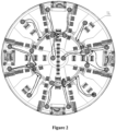
Figure 2 is a diagram showing the distribution of a hydraulic pipeline in the tunnel boring machine cutter head according to the present application; -
Figure 3 is a diagram showing the distribution of freezing portions in the tunnel boring machine cutter head according to the present application; and -
Figure 4 is a diagram showing the covering areas of the freezing portions in the tunnel boring machine cutter head according to the present application. - Reference numerals in
Figure 1 to 4 :1 main spoke arm, 2 ring beam, 3 secondary spoke arm, 4 central cylinder, 5 central cutter, 6 hobbing cutter, 7 serrated cutter, 8 slicer, 9 scraper, 10 closed chamber, 11 freezing portion, 12 freezing pipeline, 13 hydraulic oil cylinder, 14 hydraulic pipeline, 15 outer peripheral freezing pipeline. - The technical solutions according to the embodiments of the present application will be described clearly and completely as follows in conjunction with the drawings in the embodiments of the present application. It is apparent that the described embodiments are only a part of the embodiments according to the present application, rather than all the embodiments. Based on the embodiments in the present application, all of other embodiments, made by those skilled in the art without any creative efforts, fall into the scope of the present application.
- A core of the present application is to provide a tunnel boring machine cutter head which can ensure safe replacement of the cutter. Another core of the present application is to provide a tunnel boring machine including the tunnel boring machine cutter head, the cutter of which can be replaced safely. Yet another core of the present application is to provide a method for replacing the cutter applied to the tunnel boring machine cutter head, according to which the cutter can be safely replaced.
- In a specific embodiment of the tunnel boring machine cutter head according to the present application, as shown in
Figures 1 to 4 , the tunnel boring machine cutter head includes a cutter head body. The cutter head body is provided with mounting holes which penetrate through the cutter head body. Freezingportions 11 are provided in the mounting holes, and each freezingportion 11 is connected with a driving device configured to drive the freezingportion 11 to extend from or retract to the cutter head body. The freezingportions 11 are connected to a freezingpipeline 12 configured to supply freezing medium for the freezingportions 11. Preferably, the freezing medium is a freezing liquid such as cold water. - During the tunneling process, the freezing
portions 11 are retracted relative to the mounting holes to prevent the freezingportions 11 from affecting the normal operation of the cutter head and avoid the wear and damage of the freezingportions 11 brought by the cutter head during the rotating operation. When an operation of replacing the cutter is required, especially when the operation of replacing the cutter is required under harsh environmental conditions, the driving devices drive the freezingportion 11 to extend from the mounting hole and into the soil or slurry in the heading face in front of the cutter head to a certain depth, and the freezing medium is transported to the freezingportion 11. Through the freezing effect of the freezing medium in the freezingportion 11, the soil in the heading face is frozen into a freezing isolation layer with higher strength and stability, and the groundwater can be effectively prevented from infiltrating into the cutter head. - It should be noted that, referring to
Figure 4 , the number of the freezingportions 11 may be set according to actual needs. Specifically, a freezing range of all freezingportions 11 should cover the entire heading face of the cutter head. The extension and retraction direction of the freezingportion 11 is preferably the tunneling direction along the axis of the cutter head. Apparently, the number and connection form of the freezingpipeline 12 may be set according to the structure of the cutter head or other needs. - In this embodiment, since the tunnel boring machine cutter head is provided with retractable freezing
portions 11, during operations of replacing or maintaining the cutter, the freezingportions 11 can freeze the soil at the front end of the heading face in an insertion points manner to form a freezing isolation layer, thereby improving the strength and stability of the soil of the heading face and providing a safe and convenient operating environment for the operations of replacing cutter. Besides, since the freezingportions 11 extend from the cutter head body, the freezing of the cutter head steel structure can be reduced, and the ineffective operations of breaking the frozen soil of the soil sump can be reduced. - Further, a
closed chamber 10 is provided in the cutter head body, the mounting holes are arranged on a side wall of the closed chamber and penetrate through the side wall, and the freezingpipeline 12 is provided in theclosed chamber 10. During the tunneling process, since the freezingpipeline 12 is arranged in theclosed chamber 10, unnecessary wear of the freezingpipeline 12 can be effectively avoided. - Further, all the freezing
portions 11 may be divided into multiple groups. The freezingportions 11 in each group are sequentially connected by the freezingpipeline 12 to form a freezing loop, and one group of the freezingportions 11 corresponds to one freezing loop. In this embodiment, the arrangement of the freezing loop can reduce the overall space occupied by the freezingpipeline 12. The number of the freezing loops may be set according to actual conditions. For example, all freezingportions 11 may be connected in series via the freezingpipeline 12 to form a single freezing loop. In addition, the inlet and outlet of the freezingpipeline 12 may be provided at the center of the cutter head body. - On the basis of any one of the foregoing embodiments, each freezing
portion 11 may be correspondingly provided with a driving device, so as to individually control the extension and retraction of each freezingportion 11 according to actual needs. - Further, the driving device may be a
hydraulic oil cylinder 13, which is convenient for maintenance. Thehydraulic oil cylinder 13 may be connected with ahydraulic pipeline 14 which is arranged in theclosed chamber 10, so as to avoid damage to thehydraulic pipeline 14 during the movement of the cutter head. Apparently, the number and connection form of thehydraulic pipeline 14 may be set according to the structure of the cutter head or other needs. - Further, all the
hydraulic oil cylinders 13 may be divided into multiple groups. Each of thehydraulic oil cylinders 13 in each group has an oil supply port connected to a same main oil supply pipeline and an oil return port connected to a same main oil return pipeline. Specifically, the main oil supply pipeline may be connected to the oil supply ports of thehydraulic oil cylinders 13 through branch oil supplyhydraulic pipelines 14, and the main oil return pipeline is connected to the oil return ports of thehydraulic oil cylinders 13 through branch oil returnhydraulic pipelines 14. For each group ofhydraulic oil cylinders 13, the hydraulic oil can be diverged to the oil supply ports of eachhydraulic oil cylinder 13 through a single input junction, and can be converged to the oil return ports of thehydraulic oil cylinders 13 at a single output junction, which is beneficial to reducing the number and space occupation of hydraulic pipelines. - Apparently, in addition to the
hydraulic oil cylinder 13, the driving device may be configured as an air cylinder or other driving device. - On the basis of any one of the above embodiments, an outer peripheral freezing
pipeline 15 in an annular shape may be provided on the outer periphery of the cutter head body, and a central axis of the outer peripheral freezingpipeline 15 is parallel or collinear with a central axis of the cutter head body. With the arrangement of the outer peripheral freezingpipeline 15, a closed freezing isolation ring can be formed after freezing the soil, which can further improve the strength of the soil after freezing, and the freezing isolation ring and the freezing region formed by the freezingportions 11 can together form a semi-closed freezing isolation enclosing region that wraps the front end of the cutter head, which effectively prevents the groundwater from infiltrating into the cutter head and the soil sump wrapped in this region and further provides a safe and convenient operating environment for the operations of replacing the cutters replacement operations. - On the basis of any one of the above embodiments, referring to
Figure 3 , the freezingportion 11 has a pipe-in-pipe structure, and is a semi-closed structure that opens toward the inside of theclosed chamber 10, and an open end of the freezingportion 11 is connected to the freezing pipeline, which can prevent the leakage of the freezing medium from the freezingportion 11. According to the present invention, the freezingportion 11 includes multiple annular sleeves sleeved in sequence. One end of the innermost annular sleeve is closed and the other end is provided with an opening for the freezing medium to enter. All the other annular sleeves have two open ends, and each annular sleeve is hermetically connected to the adjacent outer annular sleeve, and each annular sleeve can extend or retract relative to the adjacent outer annular sleeve. By controlling the extension length of each annular sleeve, the extension depth of the freezingportion 11 into the heading face can be controlled, which is more flexible to use and can be retracted when not in use to reduce space occupation. - On the basis of any one of the above embodiments, referring to
Figures 1 and2 , the cutter head body includes a central cylinder 4 and spoke arms, and the spoke arms include main spoke arms 1 and secondary spoke arms 3. All the main spoke arms 1 are radially distributed around the central cylinder 4 and connected to the central cylinder 4, the secondary spoke arms 3 are connected between adjacent main spoke arms 1 throughring beams 2, and the connection strength between the main spoke arm 1 and the secondary spoke arm 3 is reliable. Theclosed chambers 10 are provided in the central cylinder 4 and the spoke arms. The spoke arms may be box girders, so that the freezingportions 11 can be placed on both the spoke arms and the central cylinder 4 to ensure the freezing area. The central cylinder 4 may be equipped with acentral cutter 5, and the main spoke arm 1 and the secondary spoke arm 3 may be equipped with multiple replaceable hobbing cutters 6, serrated cutters 7, slicers 8, and scrapers 9. - The position of the driving device may be set according to actual needs. For example, the driving device may be arranged at the rear of the spoke arm, and the piston rod of the driving device extends into the
closed chamber 10 of the spoke arm and is connected with the freezingportion 11. - In addition to the above tunnel boring machine cutter head, a tunnel boring machine is further provided according to the present application. The tunnel boring machine includes a tunnel boring machine cutter head, and the tunnel boring machine cutter head is the tunnel boring machine cutter head according to any one of the above embodiments. Accordingly, for the beneficial effects of the tunnel boring machine, reference may be made to the above embodiments. Reference may be made to the conventional technology for the structure of the other parts of the tunnel boring machine, which will not be described here.
- Besides, a method for replacing cutters is further provided according to the present application, which is applied to the tunnel boring machine cutter head in any one of the above embodiments. The method for replacing the cutters specifically includes the following steps:
- driving, by the driving device in the tunnel boring machine cutter head, the freezing portions in the tunnel boring machine cutter head to extend from the mounting holes in the tunnel boring machine cutter head and to extend into the heading face in front of the cutter head to a certain depth; and
- providing the freezing medium to the freezing portions to freeze the soil of the heading face into a freezing isolation layer.
- According to the method for replacing cutters provided by the present application, the cutters can be safely replaced.
- The above embodiments are described in a progressive manner. Each of the embodiments mainly focuses on describing its differences from other embodiments, and references may be made among these embodiments with respect to the same or similar parts.
- The tunnel boring machine, the tunnel boring machine cutter head, and the cutter replacement method for the tunnel boring machine cutter head provided by the present application have been introduced in detail hereinbefore. The principle and the embodiments of the present application are illustrated herein by specific examples. The above description of examples is only intended to help the understanding of the present application. It should be noted that, for those skilled in the art, many modifications and improvements may be made to the present application without departing from the principle of the present application, defined by the claims.
Claims (9)
- A tunnel boring machine cutter head comprising:a cutter head body, whereinthe cutter head body is provided with mounting holes which penetrate through the cutter head body;freezing portions (11) are provided in the mounting holes, the freezing portions (11) are connected with driving devices configured to drive the freezing portions (11) to extend from or retract to the cutter head body; andthe freezing portions (11) are connected to a freezing pipeline (12) configured to supply freezing medium for the freezing portions (11),wherein a chamber (10) is provided in the cutter head body, the mounting holes are arranged on a side wall of the chamber (10) and penetrate through the side wall, and the freezing pipeline (12) is provided in the chamber (10),characterized in that, each of the freezing portions (11) has a pipe-in-pipe structure and is a semi-closed structure that opens toward an inside of the chamber (10), and an open end of the freezing portion (11) is connected to the freezing pipeline (12),the freezing portion (11) include multiple annular sleeves sleeved in sequence, one end of the innermost annular sleeve is closed and the other end is provided with an opening for the freezing medium to enter, all the other annular sleeves have two open ends, and each annular sleeve is hermetically connected to the adjacent outer annular sleeve, and each annular sleeve can extend or retract relative to the adjacent outer annular sleeve, by controlling the extension length of each annular sleeve, the extension depth of the freezing portion (11) into a heading face can be controlled.
- The tunnel boring machine cutter head according to claim 1, whereinthe freezing portions (11) are divided into a plurality of groups; andthe freezing portions (11) in each group are sequentially connected by the freezing pipeline (12) to form a freezing loop.
- The tunnel boring machine cutter head according to claim 2, wherein each of the freezing portions (11) is correspondingly provided with the driving devices.
- The tunnel boring machine cutter head according to claim 2, wherein each of the driving devices is a hydraulic oil cylinder (13), the hydraulic oil cylinder (13) is connected with a hydraulic pipeline (14), and the hydraulic pipeline (14) is provided in the chamber (10).
- The tunnel boring machine cutter head according to claim 4, whereinthe hydraulic oil cylinders (13) are divided into a plurality of groups; andeach of the hydraulic oil cylinders (13) in each group has an oil supply port connected to a same main oil supply pipeline and an oil return port connected to a same main oil return pipeline.
- The tunnel boring machine cutter head according to any one of claims 1 to 5, wherein an outer peripheral freezing pipeline (15) in an annular shape is provided on an outer periphery of the cutter head body and a central axis of the outer peripheral freezing pipeline (15) is parallel or collinear with a central axis of the cutter head body.
- The tunnel boring machine cutter head according to claim 6, wherein the cutter head body comprises a central cylinder (4) and spoke arms, and the spoke arms comprise main spoke arms (1) and secondary spoke arms (3); and
all the main spoke arms (1) are radially distributed around the central cylinder (4) and connected to the central cylinder (4), the secondary spoke arms (3) are connected between adjacent main spoke arms (1) through ring beams (2), and the chambers (10) are provided in the central cylinder (4) and the spoke arms. - A tunnel boring machine comprising a tunnel boring machine cutter head, characterized in that the tunnel boring machine cutter head is the tunnel boring machine cutter head according to any one of claims 1 to 7.
- A cutter replacement method for the tunnel boring machine cutter head according to any one of claims 1 to 7, characterized in that the method comprises:driving, by the driving devices in the tunnel boring machine cutter head, the freezing portions (11) in the tunnel boring machine cutter head to extend from the mounting holes in the tunnel boring machine cutter head and to extend into a heading face in front of the cutter head to a certain depth;providing freezing medium to the freezing portions (11) to freeze soil of the heading face into a freezing isolation layer; andreplacing cutters provided in the cutter head.
Applications Claiming Priority (2)
| Application Number | Priority Date | Filing Date | Title |
|---|---|---|---|
| CN201810707625.XA CN108843336B (en) | 2018-07-02 | 2018-07-02 | Heading machine, heading machine cutterhead and cutter changing method |
| PCT/CN2018/124323 WO2020007004A1 (en) | 2018-07-02 | 2018-12-27 | Tunnel boring machine, tunnel boring machine cutter disc and cutter replacement method |
Publications (3)
| Publication Number | Publication Date |
|---|---|
| EP3819461A1 EP3819461A1 (en) | 2021-05-12 |
| EP3819461A4 EP3819461A4 (en) | 2022-03-30 |
| EP3819461B1 true EP3819461B1 (en) | 2024-05-01 |
Family
ID=64200090
Family Applications (1)
| Application Number | Title | Priority Date | Filing Date |
|---|---|---|---|
| EP18925474.1A Active EP3819461B1 (en) | 2018-07-02 | 2018-12-27 | Tunnel boring machine, tunnel boring machine cutter disc and cutter replacement method |
Country Status (4)
| Country | Link |
|---|---|
| EP (1) | EP3819461B1 (en) |
| CN (1) | CN108843336B (en) |
| SG (1) | SG11202013241UA (en) |
| WO (1) | WO2020007004A1 (en) |
Families Citing this family (7)
| Publication number | Priority date | Publication date | Assignee | Title |
|---|---|---|---|---|
| CN108843336B (en) * | 2018-07-02 | 2024-02-02 | 中国铁建重工集团股份有限公司 | Heading machine, heading machine cutterhead and cutter changing method |
| WO2020093590A1 (en) * | 2018-11-08 | 2020-05-14 | 大连理工大学 | Full-section tunnel boring machine cutter replacing robot and cutter system matched with same |
| CN109403992B (en) * | 2018-11-27 | 2024-03-22 | 中铁工程装备集团有限公司 | Freezing blade disc arrangement structure |
| CN109989764A (en) * | 2019-05-21 | 2019-07-09 | 中国铁建重工集团股份有限公司 | Normal pressure tool changing cutter head with freezing function |
| CN116122837A (en) * | 2023-01-17 | 2023-05-16 | 中铁工程装备集团有限公司 | Active rollback cutterhead and heading machine |
| CN116427947A (en) * | 2023-04-25 | 2023-07-14 | 中铁十六局集团有限公司 | A shield machine cutter head |
| CN118933821A (en) * | 2024-09-04 | 2024-11-12 | 中交路桥建设有限公司 | TBM machine with excavation expansion function and excavation expansion method |
Family Cites Families (37)
| Publication number | Priority date | Publication date | Assignee | Title |
|---|---|---|---|---|
| JPS5581996A (en) * | 1978-12-13 | 1980-06-20 | Seiken Co | Method of producing frozen soil in front of shield machine |
| DE3140672A1 (en) * | 1981-10-13 | 1983-04-28 | Linde Ag, 6200 Wiesbaden | METHOD FOR CREATING A TUNNEL |
| JPH07109157B2 (en) * | 1989-03-02 | 1995-11-22 | 株式会社熊谷組 | Ground improvement method using shield machine |
| JP2676011B2 (en) * | 1989-06-09 | 1997-11-12 | 建設省土木研究所長 | Ground improvement method in tunnel excavation |
| JPH077433Y2 (en) * | 1989-11-20 | 1995-02-22 | 大成建設株式会社 | Freeze tube |
| JP2869569B2 (en) * | 1990-03-06 | 1999-03-10 | 株式会社竹中工務店 | Construction method of large depth, large scale underground space by ground freezing method and ground freezing pipe |
| JPH06102957B2 (en) * | 1990-08-24 | 1994-12-14 | 鉄建建設株式会社 | Underground joining method of shield tunnel |
| JP3168345B2 (en) * | 1991-07-15 | 2001-05-21 | 飛島建設株式会社 | Underground joining shield machine and tunnel joining method using it |
| US5626201A (en) * | 1993-09-20 | 1997-05-06 | Excavation Engineering Associates, Inc. | Disc cutter and method of replacing disc cutters |
| JP2740737B2 (en) * | 1994-05-02 | 1998-04-15 | 川崎重工業株式会社 | Cutter disk of different diameter shield machine for excavation of different diameter tunnel, its underground joining device and its underground joining method |
| JP3471457B2 (en) * | 1994-12-02 | 2003-12-02 | 川崎重工業株式会社 | Shielding machine for tunneling of different diameter |
| JP3359486B2 (en) * | 1996-02-29 | 2002-12-24 | 日立造船株式会社 | Method of joining tunnels of different diameters using shield machine |
| SG102583A1 (en) * | 1999-07-14 | 2004-03-26 | Mitsubishi Heavy Ind Ltd | Method for replacing cutters of tunnel-excavating machine, method for excavating tunnel, and tunnel-excavating machine |
| JP2001107684A (en) * | 1999-10-05 | 2001-04-17 | Kawasaki Heavy Ind Ltd | Shield excavator cutter replacement method and shield excavator |
| JP3574841B2 (en) * | 2000-01-26 | 2004-10-06 | 五洋建設株式会社 | Shield excavator cutter bit changing device |
| JP4193569B2 (en) * | 2003-05-08 | 2008-12-10 | 鹿島建設株式会社 | Freezing method and freezing equipment for the propulsion pipe reach |
| JP2007077682A (en) * | 2005-09-14 | 2007-03-29 | Tokyo Gas Co Ltd | Shield machine and working area forming method therefor |
| JP5038058B2 (en) * | 2007-08-13 | 2012-10-03 | 鹿島建設株式会社 | Shield machine and freezing method in chamber |
| JP4885815B2 (en) * | 2007-09-21 | 2012-02-29 | 鹿島建設株式会社 | Cleaning method and apparatus for tail seal in shield machine |
| JP2009293205A (en) * | 2008-06-03 | 2009-12-17 | Shimizu Corp | Tunnel excavation method |
| KR101282945B1 (en) * | 2011-11-17 | 2013-07-08 | 한국철도기술연구원 | Tunnel Boring Machine |
| KR20130107875A (en) * | 2012-03-23 | 2013-10-02 | 원우기술개발 주식회사 | Boring machine having braker for pile driving |
| CN103590835A (en) * | 2013-11-28 | 2014-02-19 | 北京中煤矿山工程有限公司 | PVC freezing pipe for shield tunneling freeze-consolidation |
| JP6594003B2 (en) * | 2015-03-05 | 2019-10-23 | 西松建設株式会社 | Freezing method and freezing device for shield tunnel construction |
| CN104790961B (en) * | 2015-04-27 | 2016-08-31 | 海南大学 | A kind of shield tunnel termination vertical cup type consolidation by freezing structure and method |
| WO2017083119A1 (en) * | 2015-11-10 | 2017-05-18 | The Robbins Company | Cutter disc with set back teeth for tunnel boring machine |
| CN105298505B (en) * | 2015-11-16 | 2017-08-18 | 中国铁建重工集团有限公司 | An earth pressure balance shield machine with freezing function and its tool changing method |
| CN105298506B (en) * | 2015-11-16 | 2017-11-07 | 中国铁建重工集团有限公司 | A kind of slurry balance shield machine with freezing function |
| CN105422108B (en) * | 2015-11-16 | 2017-11-10 | 广东华隧建设股份有限公司 | A kind of cutter replacing method based on the slurry balance shield machine with freezing function |
| JP6687976B2 (en) * | 2016-03-16 | 2020-04-28 | ケミカルグラウト株式会社 | Freezing method |
| CN106285713B (en) * | 2016-08-31 | 2019-02-19 | 中国铁建重工集团有限公司 | Cutter head for rock tunnel development machine |
| DE202016105272U1 (en) * | 2016-09-22 | 2016-10-19 | Wimmer Hartstahl Gesellschaft m. b. H. & Co. KG | Device for cutting solid material |
| CN106522970A (en) * | 2016-12-30 | 2017-03-22 | 中铁工程装备集团有限公司 | Shield cutter head with refrigeration function and shield tunneling machine |
| CN107387100B (en) * | 2017-08-22 | 2023-08-18 | 中铁工程装备集团有限公司 | Shield constructs machine that possesses freezing reinforcement function |
| CN108005663A (en) * | 2017-12-18 | 2018-05-08 | 上海市基础工程集团有限公司 | Export & import exempts from tube drawing consolidation by freezing construction method |
| CN208473872U (en) * | 2018-07-02 | 2019-02-05 | 中国铁建重工集团有限公司 | Development machine and its development machine cutterhead |
| CN108843336B (en) * | 2018-07-02 | 2024-02-02 | 中国铁建重工集团股份有限公司 | Heading machine, heading machine cutterhead and cutter changing method |
-
2018
- 2018-07-02 CN CN201810707625.XA patent/CN108843336B/en active Active
- 2018-12-27 EP EP18925474.1A patent/EP3819461B1/en active Active
- 2018-12-27 SG SG11202013241UA patent/SG11202013241UA/en unknown
- 2018-12-27 WO PCT/CN2018/124323 patent/WO2020007004A1/en not_active Ceased
Also Published As
| Publication number | Publication date |
|---|---|
| CN108843336A (en) | 2018-11-20 |
| EP3819461A1 (en) | 2021-05-12 |
| SG11202013241UA (en) | 2021-01-28 |
| CN108843336B (en) | 2024-02-02 |
| EP3819461A4 (en) | 2022-03-30 |
| WO2020007004A1 (en) | 2020-01-09 |
Similar Documents
| Publication | Publication Date | Title |
|---|---|---|
| EP3819461A1 (en) | Tunnel boring machine, tunnel boring machine cutter disc and cutter replacement method | |
| CN110259474A (en) | Thread hob hydraulic-mechanical TBM cutterhead combined-breaking rock method and its digging device | |
| CN211648175U (en) | Hydraulic cutting tool module and hydraulic-mechanical combined rock breaking TBM device | |
| KR20050030133A (en) | Shield tunneling machine | |
| CN110847926A (en) | Hydraulic cutting tool module and combined rock breaking TBM device and method | |
| CN107165647B (en) | Shield tunneling machine for soft soil layer tunnel construction | |
| US5221160A (en) | Subterranean connecting method for construction of shield tunnel and connecting apparatus therefor | |
| JPS5845558B2 (en) | Messel shield especially for digging underground tunnels etc. | |
| CN214997663U (en) | Cantilever heading machine for assisting rock breaking by using high-pressure water | |
| KR100770243B1 (en) | Tunnel Excavator with Laser Nozzle | |
| CN112483105B (en) | Rock Breaking Method of Internal and External Cutter TBM Based on Pulse Jet + Point Treatment | |
| CN109779650B (en) | Tunnel tunneling device | |
| CN115749807B (en) | Non-circular tunnel tunneling equipment and excavating method | |
| JP2004092141A (en) | Tunnel excavator | |
| CN210685991U (en) | Mechanical-hydraulic combined rock breaking TBM tunneling equipment | |
| CN113622936A (en) | Novel tunneling method and tunneling device | |
| CN214836351U (en) | Shield machine with anti-jamming shield function | |
| CN213743415U (en) | Shield cutter head mud cake prevention and control device | |
| JP3171459B2 (en) | Shield method | |
| JP4031808B2 (en) | Excavator | |
| CN208473872U (en) | Development machine and its development machine cutterhead | |
| EP0393187B1 (en) | Method and apparatus for connecting halves of shield tunnel under ground | |
| JPH0546440B2 (en) | ||
| CN117684999B (en) | Tunnel boring machine and diameter changing method thereof | |
| CN214697850U (en) | Earth pressure balance shield small-curve-radius tunnel shield tunneling device |
Legal Events
| Date | Code | Title | Description |
|---|---|---|---|
| STAA | Information on the status of an ep patent application or granted ep patent |
Free format text: STATUS: THE INTERNATIONAL PUBLICATION HAS BEEN MADE |
|
| PUAI | Public reference made under article 153(3) epc to a published international application that has entered the european phase |
Free format text: ORIGINAL CODE: 0009012 |
|
| STAA | Information on the status of an ep patent application or granted ep patent |
Free format text: STATUS: REQUEST FOR EXAMINATION WAS MADE |
|
| 17P | Request for examination filed |
Effective date: 20210113 |
|
| AK | Designated contracting states |
Kind code of ref document: A1 Designated state(s): AL AT BE BG CH CY CZ DE DK EE ES FI FR GB GR HR HU IE IS IT LI LT LU LV MC MK MT NL NO PL PT RO RS SE SI SK SM TR |
|
| DAV | Request for validation of the european patent (deleted) | ||
| DAX | Request for extension of the european patent (deleted) | ||
| A4 | Supplementary search report drawn up and despatched |
Effective date: 20220224 |
|
| RIC1 | Information provided on ipc code assigned before grant |
Ipc: E21D 9/00 20060101ALI20220220BHEP Ipc: E21D 9/10 20060101AFI20220220BHEP |
|
| RIN1 | Information on inventor provided before grant (corrected) |
Inventor name: DENG, RUQUN Inventor name: LUO, DAN Inventor name: XIONG, CHENJUN Inventor name: JI, ZHIYONG Inventor name: XUE, JING Inventor name: PENG, ZHENGYANG Inventor name: HE, QIPING Inventor name: CHENG, YONGLIANG Inventor name: LIU, FEIXIANG |
|
| GRAP | Despatch of communication of intention to grant a patent |
Free format text: ORIGINAL CODE: EPIDOSNIGR1 |
|
| STAA | Information on the status of an ep patent application or granted ep patent |
Free format text: STATUS: GRANT OF PATENT IS INTENDED |
|
| RIC1 | Information provided on ipc code assigned before grant |
Ipc: E21D 9/00 20060101ALI20231116BHEP Ipc: E21D 9/10 20060101AFI20231116BHEP |
|
| INTG | Intention to grant announced |
Effective date: 20231129 |
|
| P01 | Opt-out of the competence of the unified patent court (upc) registered |
Effective date: 20240129 |
|
| GRAS | Grant fee paid |
Free format text: ORIGINAL CODE: EPIDOSNIGR3 |
|
| GRAA | (expected) grant |
Free format text: ORIGINAL CODE: 0009210 |
|
| STAA | Information on the status of an ep patent application or granted ep patent |
Free format text: STATUS: THE PATENT HAS BEEN GRANTED |
|
| AK | Designated contracting states |
Kind code of ref document: B1 Designated state(s): AL AT BE BG CH CY CZ DE DK EE ES FI FR GB GR HR HU IE IS IT LI LT LU LV MC MK MT NL NO PL PT RO RS SE SI SK SM TR |
|
| REG | Reference to a national code |
Ref country code: GB Ref legal event code: FG4D |
|
| REG | Reference to a national code |
Ref country code: CH Ref legal event code: EP |
|
| REG | Reference to a national code |
Ref country code: IE Ref legal event code: FG4D |
|
| REG | Reference to a national code |
Ref country code: DE Ref legal event code: R096 Ref document number: 602018069140 Country of ref document: DE |
|
| REG | Reference to a national code |
Ref country code: LT Ref legal event code: MG9D |
|
| REG | Reference to a national code |
Ref country code: NL Ref legal event code: MP Effective date: 20240501 |
|
| PG25 | Lapsed in a contracting state [announced via postgrant information from national office to epo] |
Ref country code: IS Free format text: LAPSE BECAUSE OF FAILURE TO SUBMIT A TRANSLATION OF THE DESCRIPTION OR TO PAY THE FEE WITHIN THE PRESCRIBED TIME-LIMIT Effective date: 20240901 |
|
| PG25 | Lapsed in a contracting state [announced via postgrant information from national office to epo] |
Ref country code: BG Free format text: LAPSE BECAUSE OF FAILURE TO SUBMIT A TRANSLATION OF THE DESCRIPTION OR TO PAY THE FEE WITHIN THE PRESCRIBED TIME-LIMIT Effective date: 20240501 |
|
| PG25 | Lapsed in a contracting state [announced via postgrant information from national office to epo] |
Ref country code: HR Free format text: LAPSE BECAUSE OF FAILURE TO SUBMIT A TRANSLATION OF THE DESCRIPTION OR TO PAY THE FEE WITHIN THE PRESCRIBED TIME-LIMIT Effective date: 20240501 Ref country code: FI Free format text: LAPSE BECAUSE OF FAILURE TO SUBMIT A TRANSLATION OF THE DESCRIPTION OR TO PAY THE FEE WITHIN THE PRESCRIBED TIME-LIMIT Effective date: 20240501 |
|
| PG25 | Lapsed in a contracting state [announced via postgrant information from national office to epo] |
Ref country code: GR Free format text: LAPSE BECAUSE OF FAILURE TO SUBMIT A TRANSLATION OF THE DESCRIPTION OR TO PAY THE FEE WITHIN THE PRESCRIBED TIME-LIMIT Effective date: 20240802 |
|
| PG25 | Lapsed in a contracting state [announced via postgrant information from national office to epo] |
Ref country code: PT Free format text: LAPSE BECAUSE OF FAILURE TO SUBMIT A TRANSLATION OF THE DESCRIPTION OR TO PAY THE FEE WITHIN THE PRESCRIBED TIME-LIMIT Effective date: 20240902 |
|
| REG | Reference to a national code |
Ref country code: AT Ref legal event code: MK05 Ref document number: 1682574 Country of ref document: AT Kind code of ref document: T Effective date: 20240501 |
|
| PG25 | Lapsed in a contracting state [announced via postgrant information from national office to epo] |
Ref country code: NL Free format text: LAPSE BECAUSE OF FAILURE TO SUBMIT A TRANSLATION OF THE DESCRIPTION OR TO PAY THE FEE WITHIN THE PRESCRIBED TIME-LIMIT Effective date: 20240501 |
|
| PG25 | Lapsed in a contracting state [announced via postgrant information from national office to epo] |
Ref country code: ES Free format text: LAPSE BECAUSE OF FAILURE TO SUBMIT A TRANSLATION OF THE DESCRIPTION OR TO PAY THE FEE WITHIN THE PRESCRIBED TIME-LIMIT Effective date: 20240501 |
|
| PG25 | Lapsed in a contracting state [announced via postgrant information from national office to epo] |
Ref country code: AT Free format text: LAPSE BECAUSE OF FAILURE TO SUBMIT A TRANSLATION OF THE DESCRIPTION OR TO PAY THE FEE WITHIN THE PRESCRIBED TIME-LIMIT Effective date: 20240501 |
|
| PG25 | Lapsed in a contracting state [announced via postgrant information from national office to epo] |
Ref country code: PL Free format text: LAPSE BECAUSE OF FAILURE TO SUBMIT A TRANSLATION OF THE DESCRIPTION OR TO PAY THE FEE WITHIN THE PRESCRIBED TIME-LIMIT Effective date: 20240501 |
|
| PG25 | Lapsed in a contracting state [announced via postgrant information from national office to epo] |
Ref country code: LV Free format text: LAPSE BECAUSE OF FAILURE TO SUBMIT A TRANSLATION OF THE DESCRIPTION OR TO PAY THE FEE WITHIN THE PRESCRIBED TIME-LIMIT Effective date: 20240501 |
|
| PG25 | Lapsed in a contracting state [announced via postgrant information from national office to epo] |
Ref country code: PT Free format text: LAPSE BECAUSE OF FAILURE TO SUBMIT A TRANSLATION OF THE DESCRIPTION OR TO PAY THE FEE WITHIN THE PRESCRIBED TIME-LIMIT Effective date: 20240902 Ref country code: PL Free format text: LAPSE BECAUSE OF FAILURE TO SUBMIT A TRANSLATION OF THE DESCRIPTION OR TO PAY THE FEE WITHIN THE PRESCRIBED TIME-LIMIT Effective date: 20240501 Ref country code: NO Free format text: LAPSE BECAUSE OF FAILURE TO SUBMIT A TRANSLATION OF THE DESCRIPTION OR TO PAY THE FEE WITHIN THE PRESCRIBED TIME-LIMIT Effective date: 20240801 Ref country code: NL Free format text: LAPSE BECAUSE OF FAILURE TO SUBMIT A TRANSLATION OF THE DESCRIPTION OR TO PAY THE FEE WITHIN THE PRESCRIBED TIME-LIMIT Effective date: 20240501 Ref country code: LV Free format text: LAPSE BECAUSE OF FAILURE TO SUBMIT A TRANSLATION OF THE DESCRIPTION OR TO PAY THE FEE WITHIN THE PRESCRIBED TIME-LIMIT Effective date: 20240501 Ref country code: IS Free format text: LAPSE BECAUSE OF FAILURE TO SUBMIT A TRANSLATION OF THE DESCRIPTION OR TO PAY THE FEE WITHIN THE PRESCRIBED TIME-LIMIT Effective date: 20240901 Ref country code: HR Free format text: LAPSE BECAUSE OF FAILURE TO SUBMIT A TRANSLATION OF THE DESCRIPTION OR TO PAY THE FEE WITHIN THE PRESCRIBED TIME-LIMIT Effective date: 20240501 Ref country code: GR Free format text: LAPSE BECAUSE OF FAILURE TO SUBMIT A TRANSLATION OF THE DESCRIPTION OR TO PAY THE FEE WITHIN THE PRESCRIBED TIME-LIMIT Effective date: 20240802 Ref country code: FI Free format text: LAPSE BECAUSE OF FAILURE TO SUBMIT A TRANSLATION OF THE DESCRIPTION OR TO PAY THE FEE WITHIN THE PRESCRIBED TIME-LIMIT Effective date: 20240501 Ref country code: ES Free format text: LAPSE BECAUSE OF FAILURE TO SUBMIT A TRANSLATION OF THE DESCRIPTION OR TO PAY THE FEE WITHIN THE PRESCRIBED TIME-LIMIT Effective date: 20240501 Ref country code: BG Free format text: LAPSE BECAUSE OF FAILURE TO SUBMIT A TRANSLATION OF THE DESCRIPTION OR TO PAY THE FEE WITHIN THE PRESCRIBED TIME-LIMIT Effective date: 20240501 Ref country code: AT Free format text: LAPSE BECAUSE OF FAILURE TO SUBMIT A TRANSLATION OF THE DESCRIPTION OR TO PAY THE FEE WITHIN THE PRESCRIBED TIME-LIMIT Effective date: 20240501 Ref country code: RS Free format text: LAPSE BECAUSE OF FAILURE TO SUBMIT A TRANSLATION OF THE DESCRIPTION OR TO PAY THE FEE WITHIN THE PRESCRIBED TIME-LIMIT Effective date: 20240801 |
|
| PG25 | Lapsed in a contracting state [announced via postgrant information from national office to epo] |
Ref country code: DK Free format text: LAPSE BECAUSE OF FAILURE TO SUBMIT A TRANSLATION OF THE DESCRIPTION OR TO PAY THE FEE WITHIN THE PRESCRIBED TIME-LIMIT Effective date: 20240501 |
|
| PG25 | Lapsed in a contracting state [announced via postgrant information from national office to epo] |
Ref country code: EE Free format text: LAPSE BECAUSE OF FAILURE TO SUBMIT A TRANSLATION OF THE DESCRIPTION OR TO PAY THE FEE WITHIN THE PRESCRIBED TIME-LIMIT Effective date: 20240501 |
|
| PG25 | Lapsed in a contracting state [announced via postgrant information from national office to epo] |
Ref country code: CZ Free format text: LAPSE BECAUSE OF FAILURE TO SUBMIT A TRANSLATION OF THE DESCRIPTION OR TO PAY THE FEE WITHIN THE PRESCRIBED TIME-LIMIT Effective date: 20240501 |
|
| PG25 | Lapsed in a contracting state [announced via postgrant information from national office to epo] |
Ref country code: RO Free format text: LAPSE BECAUSE OF FAILURE TO SUBMIT A TRANSLATION OF THE DESCRIPTION OR TO PAY THE FEE WITHIN THE PRESCRIBED TIME-LIMIT Effective date: 20240501 Ref country code: SK Free format text: LAPSE BECAUSE OF FAILURE TO SUBMIT A TRANSLATION OF THE DESCRIPTION OR TO PAY THE FEE WITHIN THE PRESCRIBED TIME-LIMIT Effective date: 20240501 |
|
| PG25 | Lapsed in a contracting state [announced via postgrant information from national office to epo] |
Ref country code: SM Free format text: LAPSE BECAUSE OF FAILURE TO SUBMIT A TRANSLATION OF THE DESCRIPTION OR TO PAY THE FEE WITHIN THE PRESCRIBED TIME-LIMIT Effective date: 20240501 |
|
| PG25 | Lapsed in a contracting state [announced via postgrant information from national office to epo] |
Ref country code: SM Free format text: LAPSE BECAUSE OF FAILURE TO SUBMIT A TRANSLATION OF THE DESCRIPTION OR TO PAY THE FEE WITHIN THE PRESCRIBED TIME-LIMIT Effective date: 20240501 Ref country code: SK Free format text: LAPSE BECAUSE OF FAILURE TO SUBMIT A TRANSLATION OF THE DESCRIPTION OR TO PAY THE FEE WITHIN THE PRESCRIBED TIME-LIMIT Effective date: 20240501 Ref country code: RO Free format text: LAPSE BECAUSE OF FAILURE TO SUBMIT A TRANSLATION OF THE DESCRIPTION OR TO PAY THE FEE WITHIN THE PRESCRIBED TIME-LIMIT Effective date: 20240501 Ref country code: EE Free format text: LAPSE BECAUSE OF FAILURE TO SUBMIT A TRANSLATION OF THE DESCRIPTION OR TO PAY THE FEE WITHIN THE PRESCRIBED TIME-LIMIT Effective date: 20240501 Ref country code: DK Free format text: LAPSE BECAUSE OF FAILURE TO SUBMIT A TRANSLATION OF THE DESCRIPTION OR TO PAY THE FEE WITHIN THE PRESCRIBED TIME-LIMIT Effective date: 20240501 Ref country code: CZ Free format text: LAPSE BECAUSE OF FAILURE TO SUBMIT A TRANSLATION OF THE DESCRIPTION OR TO PAY THE FEE WITHIN THE PRESCRIBED TIME-LIMIT Effective date: 20240501 |
|
| REG | Reference to a national code |
Ref country code: DE Ref legal event code: R097 Ref document number: 602018069140 Country of ref document: DE |
|
| PLBE | No opposition filed within time limit |
Free format text: ORIGINAL CODE: 0009261 |
|
| STAA | Information on the status of an ep patent application or granted ep patent |
Free format text: STATUS: NO OPPOSITION FILED WITHIN TIME LIMIT |
|
| 26N | No opposition filed |
Effective date: 20250204 |
|
| PG25 | Lapsed in a contracting state [announced via postgrant information from national office to epo] |
Ref country code: SI Free format text: LAPSE BECAUSE OF FAILURE TO SUBMIT A TRANSLATION OF THE DESCRIPTION OR TO PAY THE FEE WITHIN THE PRESCRIBED TIME-LIMIT Effective date: 20240501 |
|
| REG | Reference to a national code |
Ref country code: DE Ref legal event code: R119 Ref document number: 602018069140 Country of ref document: DE |
|
| PG25 | Lapsed in a contracting state [announced via postgrant information from national office to epo] |
Ref country code: MC Free format text: LAPSE BECAUSE OF FAILURE TO SUBMIT A TRANSLATION OF THE DESCRIPTION OR TO PAY THE FEE WITHIN THE PRESCRIBED TIME-LIMIT Effective date: 20240501 |
|
| REG | Reference to a national code |
Ref country code: CH Ref legal event code: PL |
|
| PG25 | Lapsed in a contracting state [announced via postgrant information from national office to epo] |
Ref country code: LU Free format text: LAPSE BECAUSE OF NON-PAYMENT OF DUE FEES Effective date: 20241227 |
|
| GBPC | Gb: european patent ceased through non-payment of renewal fee |
Effective date: 20241227 |
|
| PG25 | Lapsed in a contracting state [announced via postgrant information from national office to epo] |
Ref country code: SE Free format text: LAPSE BECAUSE OF FAILURE TO SUBMIT A TRANSLATION OF THE DESCRIPTION OR TO PAY THE FEE WITHIN THE PRESCRIBED TIME-LIMIT Effective date: 20240501 |
|
| REG | Reference to a national code |
Ref country code: BE Ref legal event code: MM Effective date: 20241231 |
|
| PG25 | Lapsed in a contracting state [announced via postgrant information from national office to epo] |
Ref country code: DE Free format text: LAPSE BECAUSE OF NON-PAYMENT OF DUE FEES Effective date: 20250701 |
|
| PG25 | Lapsed in a contracting state [announced via postgrant information from national office to epo] |
Ref country code: BE Free format text: LAPSE BECAUSE OF NON-PAYMENT OF DUE FEES Effective date: 20241231 Ref country code: GB Free format text: LAPSE BECAUSE OF NON-PAYMENT OF DUE FEES Effective date: 20241227 |
|
| PG25 | Lapsed in a contracting state [announced via postgrant information from national office to epo] |
Ref country code: FR Free format text: LAPSE BECAUSE OF NON-PAYMENT OF DUE FEES Effective date: 20241231 |
|
| PG25 | Lapsed in a contracting state [announced via postgrant information from national office to epo] |
Ref country code: CH Free format text: LAPSE BECAUSE OF NON-PAYMENT OF DUE FEES Effective date: 20241231 |
|
| PG25 | Lapsed in a contracting state [announced via postgrant information from national office to epo] |
Ref country code: IE Free format text: LAPSE BECAUSE OF NON-PAYMENT OF DUE FEES Effective date: 20241227 |
|
| PGFP | Annual fee paid to national office [announced via postgrant information from national office to epo] |
Ref country code: IT Payment date: 20251222 Year of fee payment: 8 |
|
| PGFP | Annual fee paid to national office [announced via postgrant information from national office to epo] |
Ref country code: TR Payment date: 20251205 Year of fee payment: 8 |