EP3819080A1 - An electronically controlled work center for processing glass plates, plates of stone material or plates of synthetic material - Google Patents
An electronically controlled work center for processing glass plates, plates of stone material or plates of synthetic material Download PDFInfo
- Publication number
- EP3819080A1 EP3819080A1 EP20204039.0A EP20204039A EP3819080A1 EP 3819080 A1 EP3819080 A1 EP 3819080A1 EP 20204039 A EP20204039 A EP 20204039A EP 3819080 A1 EP3819080 A1 EP 3819080A1
- Authority
- EP
- European Patent Office
- Prior art keywords
- plate
- work center
- carriages
- longitudinal direction
- suction cup
- Prior art date
- Legal status (The legal status is an assumption and is not a legal conclusion. Google has not performed a legal analysis and makes no representation as to the accuracy of the status listed.)
- Granted
Links
Images








Classifications
-
- B—PERFORMING OPERATIONS; TRANSPORTING
- B24—GRINDING; POLISHING
- B24B—MACHINES, DEVICES, OR PROCESSES FOR GRINDING OR POLISHING; DRESSING OR CONDITIONING OF ABRADING SURFACES; FEEDING OF GRINDING, POLISHING, OR LAPPING AGENTS
- B24B7/00—Machines or devices designed for grinding plane surfaces on work, including polishing plane glass surfaces; Accessories therefor
- B24B7/005—Portal grinding machines
-
- B—PERFORMING OPERATIONS; TRANSPORTING
- B24—GRINDING; POLISHING
- B24B—MACHINES, DEVICES, OR PROCESSES FOR GRINDING OR POLISHING; DRESSING OR CONDITIONING OF ABRADING SURFACES; FEEDING OF GRINDING, POLISHING, OR LAPPING AGENTS
- B24B41/00—Component parts such as frames, beds, carriages, headstocks
- B24B41/06—Work supports, e.g. adjustable steadies
- B24B41/068—Table-like supports for panels, sheets or the like
-
- B—PERFORMING OPERATIONS; TRANSPORTING
- B24—GRINDING; POLISHING
- B24B—MACHINES, DEVICES, OR PROCESSES FOR GRINDING OR POLISHING; DRESSING OR CONDITIONING OF ABRADING SURFACES; FEEDING OF GRINDING, POLISHING, OR LAPPING AGENTS
- B24B7/00—Machines or devices designed for grinding plane surfaces on work, including polishing plane glass surfaces; Accessories therefor
- B24B7/02—Machines or devices designed for grinding plane surfaces on work, including polishing plane glass surfaces; Accessories therefor involving a reciprocatingly-moved work-table
-
- B—PERFORMING OPERATIONS; TRANSPORTING
- B24—GRINDING; POLISHING
- B24B—MACHINES, DEVICES, OR PROCESSES FOR GRINDING OR POLISHING; DRESSING OR CONDITIONING OF ABRADING SURFACES; FEEDING OF GRINDING, POLISHING, OR LAPPING AGENTS
- B24B7/00—Machines or devices designed for grinding plane surfaces on work, including polishing plane glass surfaces; Accessories therefor
- B24B7/07—Machines or devices designed for grinding plane surfaces on work, including polishing plane glass surfaces; Accessories therefor involving a stationary work-table
-
- B—PERFORMING OPERATIONS; TRANSPORTING
- B24—GRINDING; POLISHING
- B24B—MACHINES, DEVICES, OR PROCESSES FOR GRINDING OR POLISHING; DRESSING OR CONDITIONING OF ABRADING SURFACES; FEEDING OF GRINDING, POLISHING, OR LAPPING AGENTS
- B24B7/00—Machines or devices designed for grinding plane surfaces on work, including polishing plane glass surfaces; Accessories therefor
- B24B7/20—Machines or devices designed for grinding plane surfaces on work, including polishing plane glass surfaces; Accessories therefor characterised by a special design with respect to properties of the material of non-metallic articles to be ground
- B24B7/22—Machines or devices designed for grinding plane surfaces on work, including polishing plane glass surfaces; Accessories therefor characterised by a special design with respect to properties of the material of non-metallic articles to be ground for grinding inorganic material, e.g. stone, ceramics, porcelain
- B24B7/24—Machines or devices designed for grinding plane surfaces on work, including polishing plane glass surfaces; Accessories therefor characterised by a special design with respect to properties of the material of non-metallic articles to be ground for grinding inorganic material, e.g. stone, ceramics, porcelain for grinding or polishing glass
- B24B7/242—Machines or devices designed for grinding plane surfaces on work, including polishing plane glass surfaces; Accessories therefor characterised by a special design with respect to properties of the material of non-metallic articles to be ground for grinding inorganic material, e.g. stone, ceramics, porcelain for grinding or polishing glass for plate glass
- B24B7/244—Machines or devices designed for grinding plane surfaces on work, including polishing plane glass surfaces; Accessories therefor characterised by a special design with respect to properties of the material of non-metallic articles to be ground for grinding inorganic material, e.g. stone, ceramics, porcelain for grinding or polishing glass for plate glass continuous
-
- B—PERFORMING OPERATIONS; TRANSPORTING
- B24—GRINDING; POLISHING
- B24B—MACHINES, DEVICES, OR PROCESSES FOR GRINDING OR POLISHING; DRESSING OR CONDITIONING OF ABRADING SURFACES; FEEDING OF GRINDING, POLISHING, OR LAPPING AGENTS
- B24B7/00—Machines or devices designed for grinding plane surfaces on work, including polishing plane glass surfaces; Accessories therefor
- B24B7/20—Machines or devices designed for grinding plane surfaces on work, including polishing plane glass surfaces; Accessories therefor characterised by a special design with respect to properties of the material of non-metallic articles to be ground
- B24B7/22—Machines or devices designed for grinding plane surfaces on work, including polishing plane glass surfaces; Accessories therefor characterised by a special design with respect to properties of the material of non-metallic articles to be ground for grinding inorganic material, e.g. stone, ceramics, porcelain
- B24B7/24—Machines or devices designed for grinding plane surfaces on work, including polishing plane glass surfaces; Accessories therefor characterised by a special design with respect to properties of the material of non-metallic articles to be ground for grinding inorganic material, e.g. stone, ceramics, porcelain for grinding or polishing glass
- B24B7/247—Machines or devices designed for grinding plane surfaces on work, including polishing plane glass surfaces; Accessories therefor characterised by a special design with respect to properties of the material of non-metallic articles to be ground for grinding inorganic material, e.g. stone, ceramics, porcelain for grinding or polishing glass using reciprocating grinding tools
-
- B—PERFORMING OPERATIONS; TRANSPORTING
- B27—WORKING OR PRESERVING WOOD OR SIMILAR MATERIAL; NAILING OR STAPLING MACHINES IN GENERAL
- B27M—WORKING OF WOOD NOT PROVIDED FOR IN SUBCLASSES B27B - B27L; MANUFACTURE OF SPECIFIC WOODEN ARTICLES
- B27M1/00—Working of wood not provided for in subclasses B27B - B27L, e.g. by stretching
- B27M1/08—Working of wood not provided for in subclasses B27B - B27L, e.g. by stretching by multi-step processes
Definitions
- the present invention relates to electronically-controlled work centers, for processing glass plates, plates of stone material or plates of synthetic material, of the type comprising:
- the work center comprises a working head movable in three orthogonal directions to perform a cycle of processing operations on a plate positioned and locked above the horizontal working surface.
- the working head is mounted on a slide movable in the vertical direction above a carriage which is - in turn - movably mounted in a horizontal direction on a bridge-like cross-member arranged in an elevated position above the horizontal working surface.
- the bridge-like cross-member is supported at its ends on the stationary structure in such a way as to be movable in a horizontal direction orthogonal to the direction of the cross-member.
- a plate is held in a fixed position on the working surface, in a horizontal position, at a certain distance from the working surface, by means of locking devices consisting of a plurality of suction cup devices, independent of each other, which are manually positioned by an operator above the horizontal working surface, according to the shape and size of the plate to be processed.
- Each device is equipped with a lower suction cup that can be activated by vacuum to lock the unit on the working surface, and an upper suction cup that can be activated by vacuum, to hold and block a plate resting thereon.
- the Applicant has proposed a work center in his European patent application EP 1 591 427 A1 provided with a belt conveyor line for conveying a plate to be machined through a working area of the work center, starting from a plate-loading area, located upstream of the working area, up to a plate-unloading area, located downstream of the working area.
- a belt conveyor line for conveying a plate to be machined through a working area of the work center, starting from a plate-loading area, located upstream of the working area, up to a plate-unloading area, located downstream of the working area.
- the transport device of the plate is a belt device, which is not able to move the plate while ensuring that the plate is precisely in a predetermined position with respect to the conveyor belts, given the possibility of sliding of the plate with respect to the belts.
- a work center according to the preamble of claim 1 is known from WO 2017/154032 A1 .
- motorized carriages carrying suction cups are used only to keep a plate locked in position during processing operations.
- the transport of the plate from the loading area to the working area and from the working area to the unloading area requires the provision of dedicated conveyors.
- the object of the invention is to provide a work center of the type indicated at the beginning of the present description by which the positioning operation of the locking devices, which are used to hold a plate to be worked on the horizontal working surface, can be performed in a completely automatic way.
- Another object of the invention is that of achieving the aforesaid object with a relatively simple machine structure of relatively low cost and without entailing any drawbacks in terms of efficiency and operational reliability.
- Another object is to provide a work center of the type specified above, which allows the feeding of a plate to be processed to be carried out in a completely automatic manner starting from a plate loading area up to the working area in the work center, and starting from the working area up to a plate unloading area.
- Another object of the invention is to provide a work center of the type indicated above wherein also the plate loading operations onto the aforesaid loading area, and the plate unloading operations from the aforesaid unloading area can be easily automated.
- Another object of the invention is to provide a work center that can be easily adapted to simultaneously perform different processing operations on different plates, so as to be advantageously used in high-productivity plants.
- Yet another object of the invention is to provide a work center of the type specified above which has a high operating flexibility and is suitable for carrying out a variety of different processing operations on the plate.
- the invention relates to an electronically-controlled work center having the characteristics of claim 1 and a method according to claim 25.
- the aforesaid at least one working head is mounted vertically-movable on a carriage which is - in turn - horizontally movable in the aforesaid transverse direction (Y) on a bridge-like cross-member, supported by the stationary structure in an elevated position above the horizontal working surface.
- the aforesaid bridge-like cross-member is fixed with respect to the stationary structure, even if the case wherein the bridge-like cross-member is movable in the longitudinal direction (X) is not excluded, so that the relative movements between the working head and the plate in the X direction may be the result of the combination of the movement of said motorized carriages and the movement of the bridge-like cross-member.
- the preferred embodiment envisages a stationary cross-member.
- the aforesaid motorized carriages carrying the locking devices are arranged aligned with each other along the aforesaid longitudinal direction (X) and can be moved independently of each other along said longitudinal direction (X), by means of respective electric drive motors.
- the aforesaid locking devices associated with each motorized carriage consist of a horizontal coplanar array of suction cup units, facing each other, which can be operated by vacuum.
- the horizontal working surface of the stationary structure of the work center is provided with supporting and guiding members in the form of rollers and/or pads or conveyor belts, to support and guide a plate during its movement in the longitudinal direction above the working surface.
- the aforesaid suction cup units are movable between a lowered rest position and a raised operative position, wherein they are able to engage the lower surface of a plate supported on said support and guide members.
- the motorized carriages are aligned with each other along a longitudinal direction, and are arranged on one side portion of the horizontal working surface.
- the aforesaid supporting and guiding members are rollers or pads arranged in longitudinal arrays, transversely spaced apart from each other, on the other side portion of the horizontal working surface, alongside the aligned series of motorized carriages.
- each of the motorized carriages carries suction cup units arranged in longitudinal lines transversely spaced apart from each other. Between these lines there are devices for supporting the plate, which can be moved vertically between a lowered rest position and a raised operative position.
- the work center comprises at least one electronic controller for controlling electric drive motors driving the aforesaid motorized carriages.
- the electronic controller is programmed in such a way that, in a preliminary step of loading a plate on the horizontal working surface, it receives information on at least one parameter indicative of a longitudinal dimension of the plate and controls the advancement of said carriages in said longitudinal direction through respective predetermined travel lengths, so as to distribute the carriages along the plate.
- the electronic controller may control a series of synchronous movements of all the carriages to bring the plate into the working area, to impart the necessary movements to the plate in the aforesaid longitudinal direction during the execution of a cycle of processing operations on the plate by said working head, and finally to transfer the processed plate into an unloading area.
- the work center according to the invention may be equipped with several working heads designed to operate simultaneously on different plates.
- the work center is set up with several aligned series of motorized carriages carrying suction cup units, to feed several plates simultaneously through the working area.
- a machine of any type for example a Cartesian robot or a multi-axis robot
- a machine of any type for automatically loading a plate onto a loading area of the work center and/or for automatically unloading a plate from an unloading area of the work center.
- At least one tool magazine is mounted movable in the longitudinal direction (X) on the stationary structure of the work center.
- the electronic controller is programmed to control a movement of said at least one tool magazine in the longitudinal direction and a movement of said working head in the transverse direction (Y) and in the vertical direction (Z), in order to arrange the working head at the magazine, every time it is necessary to carry out an automatic tool change.
- the work center has a series of important advantages.
- the plate to be processed is held by a plurality of suction cup units, which are positioned and distributed on the working surface in a completely automatic way, according to the size and configuration of the plate.
- the work center may provide one or more contact sensors or optical sensors of any known type to detect the configuration and position of the plate with respect to the working area and thus allow automatic programming of the electronic controller regarding the arrangement of the motorized carriages carrying the suction cup units.
- An additional advantage of the work center according to the invention lies in the fact that the suction cup units carried by the motorized carriages do not hold the plate in a fixed position during processing, but, on the contrary, they move the plate in the longitudinal direction (X).
- This characteristic is used both to perform the necessary relative movements in the longitudinal direction (X) between the working head and the plate during the cycle of processing operations, and to carry out the forward movement of the plate necessary to bring the plate from the loading area to the working area and from the working area to the unloading area. Therefore, even these operations no longer require the intervention of one or more operators and can be carried out in total safety (the operators can remain outside a protected working area, since they are not required to operate in the work area) and in extremely short times, to the advantage of productivity.
- the work center according to the invention may be easily configured to simultaneously perform the processing of more than one plate.
- the degree of operational flexibility of the work center according to the invention is very high.
- the work center lends itself to be easily configured both in a manual mode, wherein relatively small plates are loaded and unloaded manually by one or more operators, and in a fully automated mode.
- the work center according to the invention also lends itself to being adapted immediately and easily for installation along an automated line, in which it constitutes a station of the line.
- said motorized carriages each carry one or more transverse rows of locking devices (typically suction cup units) aligned in transverse directions with respect to said longitudinal direction, and that each carriage has a dimension in the longitudinal direction equal to or less than the dimension in the aforesaid longitudinal direction of the locking devices carried by said carriage.
- locking devices typically suction cup units
- This solution makes it possible to arrange the suction cup units carried by different carriages into positions immediately adjacent to each other, placing the carriages in contact with each other. Furthermore, this solution allows, in the event that the work center is equipped with a second and lower drilling head, minimizing the minimum distance between the suction cup unit and the lower drilling head, allowing a greater dimension of the area of the plate in which it is possible to make a hole.
- the horizontal working surface of said stationary structure is provided with an array of conveyor belts parallel and transversely spaced apart, to support and guide a plate during its movement in the longitudinal direction entering and/or exiting the working surface.
- the said conveyor belts are movable between a lowered rest position and a raised operative position, wherein they are able to engage the lower surface of a plate so as to support the plate and transfer the plate in the longitudinal direction.
- the locking devices carried by the motorized carriages are suction cup units that can are displaceable in the spaces between the conveyor belts between a lowered rest position and a raised operative position, wherein the suction cup units are able to engage the lower surface of a plate supported on said conveyor belts.
- said one or more motorized carriages carrying the locking devices are also used to support waste portions of the glass plates resulting from processing operations on the plates.
- reference 1 indicates - in its entirety - an electronically-controlled work center for processing glass plates, plates of stone material or plates of synthetic material.
- the work center 1 comprises a stationary structure 2, defining a horizontal working surface 3.
- the horizontal working surface 3 includes a working area generally indicated by A, surmounted by a bridge-like cross-member 4 arranged in an elevated position above the working area A.
- the bridge-like cross-member 4 is in a fixed position with respect to the stationary structure 2, having its ends carried by two side portions 5, which are rigidly connected to the stationary structure 2.
- the horizontal working surface 3 extends in a longitudinal horizontal direction X, while the bridge-like cross-member 4 extends in a transverse horizontal direction Y, orthogonal to the longitudinal direction X.
- a motorized carriage 6 is slidably mounted on the bridge-like cross-member 4 in the Y direction.
- a slide 7 carrying a working head H.
- the plates L are displaced in the direction X above the horizontal working surface 3 by means of a plurality of motorized carriages C, movable in the longitudinal direction X independently of each other and carrying a plurality of locking devices V configured for engaging and blocking one or more plates, kept in a horizontal position, on said carriages.
- the locking devices consist of suction cup units which can be operated by vacuum.
- the relative movements of the working head H with respect to the plate are obtained: in the X direction by the movement of the plate imparted by the motorized carriages C; in the Y direction by the movement of the carriage 6 along the bridge-like cross-member 4, and in the Z direction by the movement of the slide 7.
- Respective electric motors are provided for driving the movements of the carriages C in the longitudinal direction X; of the carriage 6 in the transverse direction Y, and of the slide 7 in the vertical direction Z.
- These electric motors are controlled by one or more electronic controllers E (see, for example, Figure 15 ), which in the illustrated embodiment example are arranged inside a cabinet associated with the stationary structure 5, which supports one end of the bridge-like cross-member 4.
- the electronic controller is equipped with a human-machine interface HMI including, for example, a monitor 10 and a keyboard 11.
- the number 8 indicates a spindle supported by the slide 7 in a rotatable way around a vertical axis, with an electric drive motor associated therewith.
- the spindle 8 has a lower end having a seat for receiving and removably supporting the conical shank 9 of a tool G (for example, a grinding wheel with a vertical axis), by means of a coupling device of any known type, configured for allowing an automatic tool change.
- a tool assembly G1 is coupled to the spindle 8, of the type illustrated - by way of example - in Figure 5 , having a conical shank 9 for coupling with the spindle 8.
- the shank 9 is connected in rotation by means of a pair of bevel gears (not illustrated) with a tool G2 (in the example a cup wheel) with a horizontal axis.
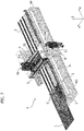
- the motorized carriages C are arranged aligned with each other in the longitudinal direction X adjacent to one side of the stationary structure 2, and are movable within a channel 200 ( Figure 1 ) defined by the stationary structure 2, below the horizontal working surface 3.
- a channel 200 ( Figure 1 ) defined by the stationary structure 2, below the horizontal working surface 3.
- longitudinal arrays of rollers R are arranged, freely rotatable around horizontal transverse axes.
- the longitudinal arrays of rollers R are transversely spaced apart.
- the plate L is intended to rest partly on the carriages C and partly on the longitudinal arrays of rollers R.
- FIGS. 3 and 4 of the attached drawings show the detail of a motorized carriage C carrying a plurality of suction cup units V.
- the suction cup units V are arranged along several spaced apart longitudinal lines, and have coplanar upper suction cups, lying in the same horizontal plane.
- Each suction cup unit is not described here in its construction details, as it can be made in any known way.
- each suction cup unit comprises a suction cup facing upwards, operated by vacuum.
- the suction cup units comprise - in a known way - inner chambers (not visible in the drawings) communicating via flexible pipes (also not illustrated) with a vacuum source, typically a pump.
- This pump may be located on board the respective carriage C, and operated by a respective electric motor, also located on board the carriage C.
- the pump that generates the vacuum may be a single pump that serves all the carriages C, located in an area of the stationary structure.
- the management of the vacuum is made independent for the various suction cup units by means of solenoid valves, each associated with a respective suction cup unit, which are governed by the central electronic control unit of the machine, depending on the size and shape of the plate to be processed.
- the suction cup units V are associated with one or more actuators of any known type (for example, fluid actuators) so as to be movable between a lowered rest position and a raised operating position, wherein the suction cups engage the lower surface of a plate L resting on the rollers R of the longitudinal arrays of rollers described above (see in particular Figure 4 ).
- each carriage C can be operated independently from that of the other carriages C.
- each carriage C is equipped with an electric motor assembly M that rotates a pinion P meshing with a rack D carried by the stationary structure 2 of the machine and extending in the longitudinal direction X.
- each carriage C is supported in a cantilever fashion and guided in its sliding movement in the X direction by means of pads 12, which engage guide bars 13 carried by the stationary structure 2 and extending in the longitudinal direction X.
- a structure C1 is associated with each motorized carriage C for containing and guiding the electrical power cables of the electrical devices located on board the carriage C, which is - in turn - connected to a catenary structure C2 (see in particular, Figure 4 ) serving to guide the aforesaid cables during the movement of the respective carriage.
- pad supports 15 are interposed, vertically-movable, with respect to the structure of the carriage (by means of fluid actuators, not illustrated), between a raised operational position and a lowered rest position.
- the supports 15 When the suction cup units of a carriage are in their lowered position, the supports 15 may be in their raised position, so that a plate L (see, for example, Figure 7 ) may be supported partly on the rollers R, in its left portion, with reference to the direction of movement of the plate (indicated by the arrow X1 in Figure 1 ) and partly on the pads of the supports 15 of the carriages C, leaving the plate free to slide forward.
- the work center provides a device 14 (see again, in particular, Figures 1-4 ), to position a plate to be processed in the transverse direction Y.
- the device 14 comprises a longitudinal bar 140, extending in the X direction carrying a plurality of vertical axis rollers 141.
- the longitudinal bar 140 can be operated by means of actuators 140A (one of which is illustrated in Figure 2 ) so as to be displaceable in the transverse direction Y in order to push the longitudinal array of rollers 141 against the right side edge of the plate L, with reference to the advancing direction of the plate (indicated by the arrow X1 in Figure 1 ), in order to push the plate into a strictly predetermined transverse position.
- the plate L In an initial step of loading a plate L on a loading area A0, at one end of the stationary structure 2 (see Figures 6 and 7 , the plate L is placed above the arrays of rollers R and on the supports 15 of the carriages C, without yet activating the suction cup units V. In this condition, the plate is positioned to the right (with reference to the advancing direction X1) beyond the correct working position.
- the bar 140 of the transverse reference device 14 is actuated so as to engage the right side edge of the plate with the rollers 141, and push the plate transversely up to a correct working position.
- the actuator or actuators of the transverse movement of the bar 14 are controlled by the electronic controller E of the work center, according to a predetermined program.
- the longitudinal bar 140 of the device 14 Once the longitudinal bar 140 of the device 14 has been positioned in this way, it remains in this position, so as to define the zero line, or faith line, for the plate during all the movements that the plate performs during the transfer step from the loading area to the working area, during the cycle of processing operations and during the transfer from the working area to the unloading area.
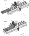
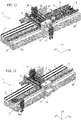
- Figures 6-11 show the different steps of loading a plate onto the working surface, according to an embodiment example.
- Figure 6 shows four carriages C carrying the suction cup units V, all arranged in mutually adjacent positions at the loading area A0 of the plate.
- the plate is schematically illustrated in a position still distant from the loading area A0.
- the work center according to the invention can be associated with devices for automatically loading and unloading the plates, even if it is not excluded, especially in the case of small sized plates, that the loading and unloading operations can be performed manually, as illustrated in Figure 13 .
- the operator can also perform a similar manual operation for unloading the plate from the unloading area of the work center.
- the work center constitutes only one station interposed along an automated processing line, in which case the loading area A0 receives the plate from the station located in the line immediately upstream of the work center.
- Figure 7 shows the plate L having arrived in a position wherein its front part overlaps the suction cup units carried by all carriages C. In this condition, the suction cup units of all the carriages are in their inoperative lowered position, with the exception of the suction cup units of the first carriage, located in the most advanced position, towards the working area A.
- Figure 8 shows precisely the condition wherein the suction cup units of the first carriage have been carried into their raised position and activated to hold the front part of the plate L thereon.
- the electronic controller of the work center activates, in a completely automatic way, according to a predetermined program, or if necessary following commands given by an operator, only the movement in the X direction of the aforesaid first carriage, while the remaining carriages are left stationary in position, with the suction cup units deactivated.
- the first carriage drags the plate L up to the position illustrated in Figure 9 , adjacent to the working area, making the plate slide over the rollers R and over the supports 15 (which are in the raised position) of the remaining carriages C at the loading area A0.
- the first carriage is kept with its suction cup units active and in engagement with the lower surface of the plate, while the other carriages C are advanced in succession, with their suction cup units in the lowered position, for different predetermined strokes, until they are distributed in mutually spaced positions along the plate, so as to cover the entire extension of the plate ( Figures 10, 11 ).
- the movement of these carriages can also be activated simultaneously with the movement of the first carriage.
- the suction cup units V are automatically distributed along the length of the plate, according to the size of the plate itself and the processing operations to be carried out.
- the plate rests on the suction cup units of the various carriages, which - at this point - are all carried into their raised operational position and made active, to hold the plate thereon.
- the plate also rests with its left part above the arrays of rollers R.
- the aforesaid operations may be controlled by the operator through the HMI interface, but more preferably they are obtained completely automatically by the electronic controller E, on the basis of a predetermined program, which is a function of the dimensions (including the thickness) of the plate, of the configuration of the plate, and the processing operations to be carried out.
- the work center is preferably equipped with sensor devices of any known type, for example, contact sensors or optical sensors (not illustrated), capable of detecting the presence of the plate and its dimensions, to allow automatic programming of the distribution of the carriages C along the plate.
- sensor devices of any known type, for example, contact sensors or optical sensors (not illustrated), capable of detecting the presence of the plate and its dimensions, to allow automatic programming of the distribution of the carriages C along the plate.
- the electronic controller and the machine may activate any cycle of processing operations programmed for processing of the plate.
- the working head H is brought alongside the portions of the plate L intended to be processed. This is achieved by moving the working head H in the Y direction and in the Z direction by moving the carriage 6 and the slide 7, and controlling a synchronous movement of all the carriages C to cause the necessary movements of the plate L (forwards or backwards) in the longitudinal direction X.
- the movement of the carriages is controlled to bring the front edge of the plate against a contact sensor, with an electric microswitch that sends a signal to the control unit indicating the starting position of the plate, with respect to the longitudinal direction X.
- the work center is designed to perform a wide range of processing operations, thanks to the provision of one or more tool magazines, which are designed to allow a fully automatic tool change on the working head H, depending on the processing to be performed.
- the work center 1 is equipped with two tool magazines.
- a first tool magazine U1 is carried by a cross-member 20 arranged parallel to and adjacent to the bridge-like cross-member 4.
- the cross-member 20 is supported by the stationary structure 2 so as to be displaceable in the X direction.
- the magazine U1 comprises a plurality of tool-holder members, made in any known way, to allow automatically depositing or picking-up of a tool assembly.
- the movements in the longitudinal direction X of the cross-member 20 with respect to the bridge-like cross-member 4 are controlled by a pneumatic actuator or, alternatively, by an electric motor (not illustrated), and are controlled by the electronic controller E of the machine.
- a second tool magazine U2 is carried by the stationary structure to a lower position than the first magazine U1.
- Figure 19 illustrates a cross-sectional view of the work center 1, in a vertical plane parallel to the X direction.
- the magazine U2 is carried by a beam 21 extending in a direction parallel to the longitudinal direction X, and displaceable with respect to the stationary structure of the work center along said longitudinal direction X.
- the movements of the structure 21 are controlled by an electric motor (not illustrated) under the control of the electronic controller E of the work center.
- the magazine U2 supports a plurality of tool-holder members - of any known type - to support a plurality of tool assemblies, for example, tool assemblies G1 of a type similar to that illustrated in Figure 5 , with a tool having a horizontal axis connected in rotation by means of a pair of bevel gears with a conical shank 9 having a vertical axis.
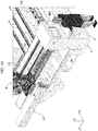
- the work center is also able to perform drilling operations, thanks to the use, in combination with the working head H, which operates above the plate, of a lower auxiliary working head LH, which operates under the plate.
- a plate drilling operation in particular, in the case of glass plates, involves the simultaneous engagement of the plate by an upper tool and a lower tool.
- the lower head LH is in the form of a transverse beam, which is slidably guided along the transverse direction Y under the stationary structure 2 of the work center.
- guide bars 25 (see Figure 19 ) slidably mounted inside guide supports 26 carried by the stationary structure may be arranged on the lower side of the beam constituting the structure of the lower cross-member LH, and/or a wheel 27 ( Figure 16 ) may be provided, always on the lower side of the head LH, and at one of its ends, freely rotatable around a horizontal axis parallel to the X direction and shaped like a pulley, so as to be guided and - at the same time - held transversely on a guide rail 28 carried by the stationary structure, in order to avoid bending during translation in the Y direction, and in order to react to the shear stress in the Z direction.
- the structure of the lower cross-member LH carries a revolver device 30, rotatable around a horizontal axis parallel to the transverse direction Y, carrying a star-like arrangement of tools 300, which are selectable according to the operation to be performed.
- the revolver device 30 is rotated so as to bring the tool to be used in the North position of the star of tools 300.
- the plate When it is necessary to perform a drilling operation on a plate L, the plate is moved in the X direction, by means of the carriages C, together with a positioning of the lower head LH along the Y direction and a positioning of the upper head H along the direction Y, respectively, below and above the plate at the point on the plate where the drilling is to be performed.
- FIG. 17 With reference to Figure 17 , inside the structure constituting the lower head LH, there is an electric motor unit M1, which is able to rotate, by means of a transmission of any known type (not illustrated), the tool 300, which is in the upper operating position in the tool star 300. Furthermore, the structure that carries the tool 300 which is in the operative position is also provided with an actuator (not shown) for imparting a movement in the Z direction to the tool 300.
- Figure 17 shows the conical shank 9 of a drilling tool G intended to engage the glass plate from the upper side. For greater clarity, Figure 17 does not illustrate the electro-spindle, to which the conical shank 9 is coupled.
- Figures 17 , 18 also show a wall W carried by the upper working head H, which surrounds the tool G when the tool is in the working position, and is intended to support nozzles for the emission of coolant liquid (not illustrated).
- a ring structure 40 surrounds the lower tool 300 when it is lowered into an operating position), and is equipped with nozzles (not illustrated) for the emission of coolant in the working area of the lower tool.
- the ring structure 40 also has a movement in the Z direction that allows it to position itself at the level of the lower surface of the plate to act as a support surface during the drilling operation.
- Figures 17 and 18 also show a cross-member 50 carried by the stationary structure and provided at the top with a series of rollers 51, aligned in the transverse direction Y, and freely rotatable around a transverse axis.
- a cross-member 50 carried by the stationary structure and provided at the top with a series of rollers 51, aligned in the transverse direction Y, and freely rotatable around a transverse axis.
- the plate L is also guided in its movements on the working area by an upper containment structure 60 ( Figure 14 ), suspended from the bridge-like cross-member 4 in a vertically adjustable position (by means of a fluid actuator not illustrated), above the plate and equipped with pad elements or freely rotating rollers, for engagement with the upper surface of the plate.
- an upper containment structure 60 Figure 14
- the bridge-like cross-member 4 suspended from the bridge-like cross-member 4 in a vertically adjustable position (by means of a fluid actuator not illustrated), above the plate and equipped with pad elements or freely rotating rollers, for engagement with the upper surface of the plate.
- Figures 15 and 16 show the lower head LH, respectively, in its two positions at opposite ends of its stroke in the Y direction.
- the carriages C are controlled simultaneously to transport the plate L to the position illustrated in Figure 12 , wherein the front portion of the plate is at the unloading area AF.
- the suction cup units of the carriages C may be deactivated and carried to their inoperative lowered positions, with the exception of the last carriage, which is further back with respect to the advancing direction of the plate.
- This carriage can be kept with its suction cup units in engagement with the plate, and then be made to advance in the X direction (the remaining carriages will, in any case, be advanced to avoid interference) so as to push the plate L towards an unloading position from the work center.
- Figure 20 shows another embodiment, wherein the configuration of the work center described above with reference to Figures 1-19 is doubled in a specular way, with two aligned series of carriages C arranged side-by-side, to simultaneously carry two plates L to be processed by two working heads H carried on the bridge-like cross-member.
- Figures 21 , 22 illustrate embodiments wherein the work center described above is associated with a machine for automatically loading the plates onto the work center.
- a Carriageesian robot 70 is arranged, carrying a gripper 71 equipped with vacuum-operated suction cup units, which is moved to subsequently pick up the plates from a support rack of the plates, and to deposit them on the working surface of the work center.
- Figure 22 illustrates a solution in which the gripper 71 is carried by a multi-axis manipulator robot 72.
- the work center can be used flexibly in a variety of ways, including a manual loading and unloading mode of small plates by one or more operators.
- the work center according to the invention may be inserted into an automated production line, so that the loading area of the work center receives, in succession, the plates that are fed by the station of the automated line, which is located upstream of the work center. Similarly, at its unloading end, the work center feeds the processed plate to the station of the automated line located downstream from the work center, or to a final unloading station for the processed plate, to which the plate is sent for shipment.
- Figures 23-27 refer to an additional embodiment of the work center according to the invention, that allows the automated feeding and processing of glass plates even with relatively small dimensions (for example, with a longitudinal dimension in the order of 400 mm).
- the working surface 3 is provided with a plurality of closed-loop conveyor belts CN arranged in the longitudinal direction of the work center, all parallel to each other and transversely spaced apart from each other, to support and guide the glass plates entering and leaving the work center.
- the conveyor belts CN also cover the area of the working surface 3 next to the channel 200 wherein the motorized carriages C are movable.
- the conveyor belts CN can be moved vertically between a raised operating position, wherein they are able to feed a glass plate entering and leaving the work center, and a lowered position, wherein they release the glass plate carried by them above the suction cup units V carried from the motorized carriages C.
- the carriages C each carry a row of suction cup units V arranged transversely to the longitudinal direction, with the suction cup units V of each carriage being transversely spaced from each other, so that the carriages C are free to move below the conveyor belts CN, and the conveyor belts CN are arranged in the spaces between the suction cup units V.
- a roller surface RS can be provided upstream of the loading area AO, as well as downstream of the unloading area AF. on which a glass plate L can be made to advance until it is picked up from the conveyor belts CN.
- each motorized carriage C carries one or more rows of suction cup units V directed transversely to the longitudinal direction of the work center (the example of Figures 23-27 shows motorized carriages C each having a single transverse row of suction cup units V), and each carriage C has a dimension in the longitudinal direction of the work center that is less than or equal to the dimension in the longitudinal direction of the suction cup units V carried by the carriage C.
- the suction cup units V carried by different carriages in positions strictly adjacent to each other, by arranging the carriages C in contact with each other, or in positions strictly adjacent to each other, as shown in Figures 24-26 .
- Figure 23 of the attached drawings is an overall perspective view of the embodiment described here, while Figures 24-26 are plan views of a detail of the loading area AO in three different operating conditions.
- Figure 4 shows a plate L in the step wherein it is transferred from the roller surface RS to two conveyor belts CN of the loading area AO. In this step, four motorized carriages C are kept in positions adjacent to each other in the loading area AO, below the conveyor belts CN.
- the step of Figure 25 shows a subsequent step, wherein the motorized carriages C have remained in their positions, while the plate L has been moved to an advanced position by the two conveyor belts CN that engage its lower surface.
- Figure 26 shows the same condition as Figure 25 , wherein, however, the longitudinal bar 14 is advanced transversely (towards the other with reference to Figure 26 ) to position the plate L in the correct position.
- the conveyor belts CN may be lowered so as to deposit the plate L on one or more suction cup units V of one or more carriages C.
- suction cup units of one or more motorized carriages C are also used to support waste portions of the glass plates resulting from processing operations on the plates.
- the suction cup units V that engage a waste portion can be moved vertically between a raised operative position and a lowered position, wherein they keep the picked-up waste portion out of the encumbrance of the working area.
- the conveyor belts CN also cover the part of the working surface 3 located next to the channel 200 in which the motorized carriages C are movable.
- the work center has a series of important advantages.
- the plate to be processed is held by a plurality of suction cup units, which are positioned and distributed on the working surface in a completely automatic way, according to the dimensions (including thickness) of the plate, the configuration of the plate, and the processing operations to be carried out.
- the work center can provide one or more contact sensors or optical sensors of any known type to detect the configuration and position of the plate with respect to the working area, and thus allow automatic programming of the electronic controller regarding the arrangement of the motorized carriages carrying the suction cup units.
- a further advantage of the work center according to the invention lies in the fact that the suction cup units carried by the motorized carriages no longer hold the plate in a fixed position during processing but, on the contrary, move the plate in the longitudinal direction (X).
- This characteristic is used both to perform the necessary relative movements in the longitudinal direction (X) between the working head and the plate during the cycle of processing operations, and to carry out the forward movement of the plate necessary to carry the plate from the loading area to the working area and from the working area to the unloading area. Therefore, even these operations no longer require the intervention of one or more operators and can be carried out in total safety (the operators can remain outside a protected working area, not needing to intervene near the area of work) and in extremely short times, to the advantage of productivity.
- the work center according to the invention can be easily configured to simultaneously perform the processing of more than one plate.
- the degree of operational flexibility of the work center according to the invention is very high.
- the work center lends itself to be easily configured both in a manual mode, wherein relatively small plates are loaded and unloaded manually by one or more operators, and in a fully automated mode.
- the work center according to the invention also lends itself to being adapted immediately and easily for installation along an automated line, in which it constitutes a station on the line.
- sensors for detecting the presence of the plate are arranged along the longitudinal direction, capable of detecting its size in the longitudinal direction of movement, in order to communicate this information to the electronic control unit, to facilitate the determination of the correct position of the carriages C.
- sensors for detecting the presence of the plate are arranged along the longitudinal direction, capable of detecting its size in the longitudinal direction of movement, in order to communicate this information to the electronic control unit, to facilitate the determination of the correct position of the carriages C.
- an automatic measurement system can be provided that detects the dimensions of the plate in the advancing direction X and in the transverse directions Y and Z, and communicates the data collected thereby to a central electronic controller.
- the senor capable of detecting the initial position of the plate along the longitudinal direction cooperates with a portion of the plate located sufficiently far away from an edge between the lower surface and a vertical side surface of the plate, so as to avoid detection of metal [RSS1] scraps present on the plate following previous cutting processes.
- said sensor is configured and arranged to cooperate with an upper part of the thickness of the plate being processed (L).
Landscapes
- Engineering & Computer Science (AREA)
- Mechanical Engineering (AREA)
- Life Sciences & Earth Sciences (AREA)
- Chemical & Material Sciences (AREA)
- Ceramic Engineering (AREA)
- Inorganic Chemistry (AREA)
- Wood Science & Technology (AREA)
- Forests & Forestry (AREA)
- Specific Conveyance Elements (AREA)
Abstract
Description
- The present invention relates to electronically-controlled work centers, for processing glass plates, plates of stone material or plates of synthetic material, of the type comprising:
- a stationary structure, defining a horizontal working surface,
- a plurality of locking devices, for retaining the plate in a horizontal position above, and at a distance from, the horizontal working surface,
- at least one working head carried in an elevated position above the horizontal working surface and capable of relative movements - with respect to a plate retained by said locking devices - in a longitudinal horizontal direction (X), in a horizontal transverse direction (Y), perpendicular to the longitudinal direction, and in a vertical direction (Z).
- A work center of the type indicated above is illustrated, for example, in the
document EP 1 779 970 A1 by the same Applicant. According to this prior art, the work center comprises a working head movable in three orthogonal directions to perform a cycle of processing operations on a plate positioned and locked above the horizontal working surface. Typically, the working head is mounted on a slide movable in the vertical direction above a carriage which is - in turn - movably mounted in a horizontal direction on a bridge-like cross-member arranged in an elevated position above the horizontal working surface. The bridge-like cross-member is supported at its ends on the stationary structure in such a way as to be movable in a horizontal direction orthogonal to the direction of the cross-member. During a cycle of processing operations, a plate is held in a fixed position on the working surface, in a horizontal position, at a certain distance from the working surface, by means of locking devices consisting of a plurality of suction cup devices, independent of each other, which are manually positioned by an operator above the horizontal working surface, according to the shape and size of the plate to be processed. Each device is equipped with a lower suction cup that can be activated by vacuum to lock the unit on the working surface, and an upper suction cup that can be activated by vacuum, to hold and block a plate resting thereon. - One of the main drawbacks of this prior art lies in the need to manually position the suction cup units on the working surface, depending on the shape and size of the plate to be positioned on the working surface, with consequent waste of time and productivity.
- In his international patent application,
WO 2019/021172 A1 , the Applicant has proposed a work center with suction cup units that are carried by motorized members guided on the working surface according to two horizontal directions orthogonal to each other. An electronic controller of the machine is thus able to automatically distribute the suction cup units on the working surface according to a predetermined program, depending upon the shape and/or size of the plate to be processed. However, this solution is not always fully satisfactory and reliable, due to the machining scraps deposited on the guides on which the support members of the suction cup units are movably mounted, and which hinder or even completely prevent the correct movement of these members. - Another drawback of the work centers of the type discussed above lies in the fact that the operations for loading the plates to be processed above the work center and for unloading the processed plates from the work center are relatively long and laborious and cannot be always easily automated. Furthermore, if the loading and unloading operations are performed manually, this entails high dead times, resulting in low productivity and also conditions wherein it is difficult to ensure a high standard of safety for the operators.
- In an attempt to solve this second problem, the Applicant has proposed a work center in his European
patent application EP 1 591 427 A1 provided with a belt conveyor line for conveying a plate to be machined through a working area of the work center, starting from a plate-loading area, located upstream of the working area, up to a plate-unloading area, located downstream of the working area. In the case of this solution, once the conveying line has carried a plate above the working area, it lowers to deposit the plate on the provided suction cup units, according to the conventional art, above the working surface, to hold the plate in place. This solution facilitates the operations necessary to bring a plate into the working area of the work center and to unload the plate from the work center, but it still retains the drawbacks associated with the need to position the suction cup units on the working surface, depending on the configuration of the plate to be processed. Furthermore, the transport device of the plate is a belt device, which is not able to move the plate while ensuring that the plate is precisely in a predetermined position with respect to the conveyor belts, given the possibility of sliding of the plate with respect to the belts. - Finally, it should be added that so-called "vertical" machines are known in the art for processing glass plates or plates of stone material or plates of composite material, wherein the plates are made to advance through a work station, keeping them in a substantially vertical position or close to vertical. A machine of this type is, for example, described in the
document EP 3 170 622 A1 by the same Applicant. In these machines, advancing of the plates through the work station is obtained by means of a plurality of suction cup units carried by one or more motorized carriages that are moved in the longitudinal horizontal direction of the machine. However, machines of this type have a series of limitations linked to the vertical positioning of the plate, especially with reference to the degree of operational flexibility of the machine and the range of operations that can be performed therewith. - A work center according to the preamble of
claim 1 is known fromWO 2017/154032 A1 . In this known solution, motorized carriages carrying suction cups are used only to keep a plate locked in position during processing operations. The transport of the plate from the loading area to the working area and from the working area to the unloading area requires the provision of dedicated conveyors. - Solutions in this field are also known from
US 2003/150240 A1 ,US 2011/003539 A1 ,EP 2 631 048 A1WO 2016/0559966 - The object of the invention is to provide a work center of the type indicated at the beginning of the present description by which the positioning operation of the locking devices, which are used to hold a plate to be worked on the horizontal working surface, can be performed in a completely automatic way.
- Another object of the invention is that of achieving the aforesaid object with a relatively simple machine structure of relatively low cost and without entailing any drawbacks in terms of efficiency and operational reliability.
- Another object is to provide a work center of the type specified above, which allows the feeding of a plate to be processed to be carried out in a completely automatic manner starting from a plate loading area up to the working area in the work center, and starting from the working area up to a plate unloading area.
- Another object of the invention is to provide a work center of the type indicated above wherein also the plate loading operations onto the aforesaid loading area, and the plate unloading operations from the aforesaid unloading area can be easily automated.
- Another object of the invention is to provide a work center that can be easily adapted to simultaneously perform different processing operations on different plates, so as to be advantageously used in high-productivity plants.
- Yet another object of the invention is to provide a work center of the type specified above which has a high operating flexibility and is suitable for carrying out a variety of different processing operations on the plate.
- In order to achieve one or more of the aforesaid objects, the invention relates to an electronically-controlled work center having the characteristics of
claim 1 and a method according toclaim 25. - In the case of a preferred embodiment, the aforesaid at least one working head is mounted vertically-movable on a carriage which is - in turn - horizontally movable in the aforesaid transverse direction (Y) on a bridge-like cross-member, supported by the stationary structure in an elevated position above the horizontal working surface. In the preferred example, the aforesaid bridge-like cross-member is fixed with respect to the stationary structure, even if the case wherein the bridge-like cross-member is movable in the longitudinal direction (X) is not excluded, so that the relative movements between the working head and the plate in the X direction may be the result of the combination of the movement of said motorized carriages and the movement of the bridge-like cross-member. The preferred embodiment, however, envisages a stationary cross-member.
- According to a further characteristic, the aforesaid motorized carriages carrying the locking devices are arranged aligned with each other along the aforesaid longitudinal direction (X) and can be moved independently of each other along said longitudinal direction (X), by means of respective electric drive motors.
- Preferably, the aforesaid locking devices associated with each motorized carriage consist of a horizontal coplanar array of suction cup units, facing each other, which can be operated by vacuum.
- In the preferred example, the horizontal working surface of the stationary structure of the work center is provided with supporting and guiding members in the form of rollers and/or pads or conveyor belts, to support and guide a plate during its movement in the longitudinal direction above the working surface. The aforesaid suction cup units are movable between a lowered rest position and a raised operative position, wherein they are able to engage the lower surface of a plate supported on said support and guide members. The motorized carriages are aligned with each other along a longitudinal direction, and are arranged on one side portion of the horizontal working surface. In one example, the aforesaid supporting and guiding members are rollers or pads arranged in longitudinal arrays, transversely spaced apart from each other, on the other side portion of the horizontal working surface, alongside the aligned series of motorized carriages. Also in the case of the aforesaid embodiment, each of the motorized carriages carries suction cup units arranged in longitudinal lines transversely spaced apart from each other. Between these lines there are devices for supporting the plate, which can be moved vertically between a lowered rest position and a raised operative position.
- According to a preferred characteristic, the work center comprises at least one electronic controller for controlling electric drive motors driving the aforesaid motorized carriages. The electronic controller is programmed in such a way that, in a preliminary step of loading a plate on the horizontal working surface, it receives information on at least one parameter indicative of a longitudinal dimension of the plate and controls the advancement of said carriages in said longitudinal direction through respective predetermined travel lengths, so as to distribute the carriages along the plate.
- After completing the loading step, when the motorized carriages carrying the suction cup units have been distributed along the length of the plate and have their suction cup units activated and in engagement on the plate, the electronic controller may control a series of synchronous movements of all the carriages to bring the plate into the working area, to impart the necessary movements to the plate in the aforesaid longitudinal direction during the execution of a cycle of processing operations on the plate by said working head, and finally to transfer the processed plate into an unloading area.
- In high productivity plants, the work center according to the invention may be equipped with several working heads designed to operate simultaneously on different plates. In this case, the work center is set up with several aligned series of motorized carriages carrying suction cup units, to feed several plates simultaneously through the working area.
- Of course, a machine of any type (for example a Cartesian robot or a multi-axis robot) can be associated with the work center according to the invention for automatically loading a plate onto a loading area of the work center and/or for automatically unloading a plate from an unloading area of the work center.
- According to an additional characteristic, at least one tool magazine is mounted movable in the longitudinal direction (X) on the stationary structure of the work center. The electronic controller is programmed to control a movement of said at least one tool magazine in the longitudinal direction and a movement of said working head in the transverse direction (Y) and in the vertical direction (Z), in order to arrange the working head at the magazine, every time it is necessary to carry out an automatic tool change.
- As is evident from the above, the work center according to the invention has a series of important advantages. First of all, the plate to be processed is held by a plurality of suction cup units, which are positioned and distributed on the working surface in a completely automatic way, according to the size and configuration of the plate. For this purpose, the work center may provide one or more contact sensors or optical sensors of any known type to detect the configuration and position of the plate with respect to the working area and thus allow automatic programming of the electronic controller regarding the arrangement of the motorized carriages carrying the suction cup units.
- An additional advantage of the work center according to the invention lies in the fact that the suction cup units carried by the motorized carriages do not hold the plate in a fixed position during processing, but, on the contrary, they move the plate in the longitudinal direction (X). This characteristic is used both to perform the necessary relative movements in the longitudinal direction (X) between the working head and the plate during the cycle of processing operations, and to carry out the forward movement of the plate necessary to bring the plate from the loading area to the working area and from the working area to the unloading area. Therefore, even these operations no longer require the intervention of one or more operators and can be carried out in total safety (the operators can remain outside a protected working area, since they are not required to operate in the work area) and in extremely short times, to the advantage of productivity.
- The automation of the positioning of the suction cup units and the automation of the movement of the plate through the work center are also obtained with an extremely simple and relatively low-cost structure, which is not exposed to any drawbacks also regarding the operational reliability over time.
- Furthermore, the work center according to the invention may be easily configured to simultaneously perform the processing of more than one plate.
- The degree of operational flexibility of the work center according to the invention is very high. The work center lends itself to be easily configured both in a manual mode, wherein relatively small plates are loaded and unloaded manually by one or more operators, and in a fully automated mode. In the latter case, the work center according to the invention also lends itself to being adapted immediately and easily for installation along an automated line, in which it constitutes a station of the line.
- In another embodiment, said motorized carriages each carry one or more transverse rows of locking devices (typically suction cup units) aligned in transverse directions with respect to said longitudinal direction, and that each carriage has a dimension in the longitudinal direction equal to or less than the dimension in the aforesaid longitudinal direction of the locking devices carried by said carriage.
- This solution makes it possible to arrange the suction cup units carried by different carriages into positions immediately adjacent to each other, placing the carriages in contact with each other. Furthermore, this solution allows, in the event that the work center is equipped with a second and lower drilling head, minimizing the minimum distance between the suction cup unit and the lower drilling head, allowing a greater dimension of the area of the plate in which it is possible to make a hole.
- According to a further optional characteristic, particularly useful for allowing the automated handling of even small plates, in said loading area and/or in said unloading area; the horizontal working surface of said stationary structure is provided with an array of conveyor belts parallel and transversely spaced apart, to support and guide a plate during its movement in the longitudinal direction entering and/or exiting the working surface. The said conveyor belts are movable between a lowered rest position and a raised operative position, wherein they are able to engage the lower surface of a plate so as to support the plate and transfer the plate in the longitudinal direction. The locking devices carried by the motorized carriages are suction cup units that can are displaceable in the spaces between the conveyor belts between a lowered rest position and a raised operative position, wherein the suction cup units are able to engage the lower surface of a plate supported on said conveyor belts.
- In an embodiment, said one or more motorized carriages carrying the locking devices are also used to support waste portions of the glass plates resulting from processing operations on the plates.
- Further characteristics and advantages of the invention will become apparent from the description that follows with reference to the attached drawings, provided purely by way of non-limiting example, wherein:
-
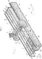
Figure 1 is a schematic perspective view of a work center according to the present invention, -
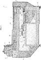
Figure 2 is a schematic cross-sectional view of the work center ofFigure 1 , in a transverse plane with respect to the longitudinal direction of the work center, -
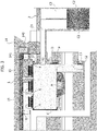
Figure 3 is an enlarged scale view of a detail of the cross-section ofFigure 2 , with reference to a concrete embodiment of the work center according to the invention, -
Figure 4 is a partial perspective view of the detail ofFigure 3 , -
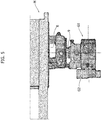
Figure 5 is a schematic side view of a tool assembly that can be associated with the working head of the work center according to the invention, -
Figures 6-13 illustrate, by way of example, different operating steps of the work center according to the invention, -
Figure 14 is a cross-sectional view of the work center, -
Figure 15 is another perspective view, partially cross-sectioned, of a detail of the work center according to the invention, -
Figure 16 shows the detail ofFigure 15 in a different operating condition, -
Figures 17 and18 show additional perspective views, partially cross-sectioned, of a detail of the assembly ofFigures 15 and16 , -
Figure 19 is a side view, partially cross-sectioned, of a part of the work center, -
Figure 20 , shows a variant of the work center according to the invention, designed to perform simultaneous processing operations of two plates, -
Figures 21 ,22 are perspective views showing two examples of machines that can be associated with the work center, for the automated loading of the plates on the work center, and -
Figures 23 - 27 illustrate an additional embodiment. - In the drawings,
reference 1 indicates - in its entirety - an electronically-controlled work center for processing glass plates, plates of stone material or plates of synthetic material. Thework center 1 comprises astationary structure 2, defining ahorizontal working surface 3. - In the example illustrated, the horizontal working
surface 3 includes a working area generally indicated by A, surmounted by a bridge-like cross-member 4 arranged in an elevated position above the working area A. - In the preferred example illustrated here, the bridge-
like cross-member 4 is in a fixed position with respect to thestationary structure 2, having its ends carried by twoside portions 5, which are rigidly connected to thestationary structure 2. - The
horizontal working surface 3 extends in a longitudinal horizontal direction X, while the bridge-like cross-member 4 extends in a transverse horizontal direction Y, orthogonal to the longitudinal direction X. - In the present description, and in the claims that follow, the terms "longitudinal" and "longitudinally" and the terms "transverse" and "transversely" are used precisely with reference to the longitudinal direction X and the transverse direction Y defined above.
- A
motorized carriage 6 is slidably mounted on the bridge-like cross-member 4 in the Y direction. On thecarriage 6, slidably mounted in the vertical direction Z is aslide 7 carrying a working head H. - The plates L are displaced in the direction X above the horizontal working
surface 3 by means of a plurality of motorized carriages C, movable in the longitudinal direction X independently of each other and carrying a plurality of locking devices V configured for engaging and blocking one or more plates, kept in a horizontal position, on said carriages. In the embodiments illustrated herein, the locking devices consist of suction cup units which can be operated by vacuum. - During a cycle of processing operations on the plate, the relative movements of the working head H with respect to the plate are obtained: in the X direction by the movement of the plate imparted by the motorized carriages C; in the Y direction by the movement of the
carriage 6 along the bridge-like cross-member 4, and in the Z direction by the movement of theslide 7. - Respective electric motors are provided for driving the movements of the carriages C in the longitudinal direction X; of the
carriage 6 in the transverse direction Y, and of theslide 7 in the vertical direction Z. These electric motors are controlled by one or more electronic controllers E (see, for example,Figure 15 ), which in the illustrated embodiment example are arranged inside a cabinet associated with thestationary structure 5, which supports one end of the bridge-like cross-member 4. The electronic controller is equipped with a human-machine interface HMI including, for example, amonitor 10 and akeyboard 11. - The constructive details of an embodiment example of the working head H are visible in
Figure 14 of the attached drawings. With reference to this Figure, thenumber 8 indicates a spindle supported by theslide 7 in a rotatable way around a vertical axis, with an electric drive motor associated therewith. - According to a known technique, the
spindle 8 has a lower end having a seat for receiving and removably supporting theconical shank 9 of a tool G (for example, a grinding wheel with a vertical axis), by means of a coupling device of any known type, configured for allowing an automatic tool change. If it is necessary to operate with a tool having a horizontal rotation axis, a tool assembly G1 is coupled to thespindle 8, of the type illustrated - by way of example - inFigure 5 , having aconical shank 9 for coupling with thespindle 8. Theshank 9 is connected in rotation by means of a pair of bevel gears (not illustrated) with a tool G2 (in the example a cup wheel) with a horizontal axis. - In the example of
Figures 1-19 , the motorized carriages C are arranged aligned with each other in the longitudinal direction X adjacent to one side of thestationary structure 2, and are movable within a channel 200 (Figure 1 ) defined by thestationary structure 2, below the horizontal workingsurface 3. On the horizontal workingsurface 3, alongside thechannel 200 in which the motorized carriages C are movable, longitudinal arrays of rollers R are arranged, freely rotatable around horizontal transverse axes. The longitudinal arrays of rollers R are transversely spaced apart. As can be seen, for example, inFigure 1 , in the case of this embodiment, the plate L is intended to rest partly on the carriages C and partly on the longitudinal arrays of rollers R. -
Figures 3 and4 of the attached drawings show the detail of a motorized carriage C carrying a plurality of suction cup units V. The suction cup units V are arranged along several spaced apart longitudinal lines, and have coplanar upper suction cups, lying in the same horizontal plane. Each suction cup unit is not described here in its construction details, as it can be made in any known way. Typically, each suction cup unit comprises a suction cup facing upwards, operated by vacuum. To this end, the suction cup units comprise - in a known way - inner chambers (not visible in the drawings) communicating via flexible pipes (also not illustrated) with a vacuum source, typically a pump. This pump may be located on board the respective carriage C, and operated by a respective electric motor, also located on board the carriage C. Alternatively, the pump that generates the vacuum may be a single pump that serves all the carriages C, located in an area of the stationary structure. In this case, the management of the vacuum is made independent for the various suction cup units by means of solenoid valves, each associated with a respective suction cup unit, which are governed by the central electronic control unit of the machine, depending on the size and shape of the plate to be processed. Furthermore, the suction cup units V are associated with one or more actuators of any known type (for example, fluid actuators) so as to be movable between a lowered rest position and a raised operating position, wherein the suction cups engage the lower surface of a plate L resting on the rollers R of the longitudinal arrays of rollers described above (see in particularFigure 4 ). - All the aforesaid construction details are not illustrated in the drawings, because they can be made in any known way, and also for greater simplicity and clarity of illustration.
- The movement of each carriage C can be operated independently from that of the other carriages C. To this end, in the example illustrated (see
Figure 3 ), each carriage C is equipped with an electric motor assembly M that rotates a pinion P meshing with a rack D carried by thestationary structure 2 of the machine and extending in the longitudinal direction X. - Still with reference to
Figures 3 and4 , in the illustrated example each carriage C is supported in a cantilever fashion and guided in its sliding movement in the X direction by means ofpads 12, which engageguide bars 13 carried by thestationary structure 2 and extending in the longitudinal direction X. - A structure C1 is associated with each motorized carriage C for containing and guiding the electrical power cables of the electrical devices located on board the carriage C, which is - in turn - connected to a catenary structure C2 (see in particular,
Figure 4 ) serving to guide the aforesaid cables during the movement of the respective carriage. - Again with reference to
Figures 3 and4 , above each carriage C, between the longitudinal rows of suction cup units V, pad supports 15 are interposed, vertically-movable, with respect to the structure of the carriage (by means of fluid actuators, not illustrated), between a raised operational position and a lowered rest position. When the suction cup units of a carriage are in their lowered position, thesupports 15 may be in their raised position, so that a plate L (see, for example,Figure 7 ) may be supported partly on the rollers R, in its left portion, with reference to the direction of movement of the plate (indicated by the arrow X1 inFigure 1 ) and partly on the pads of thesupports 15 of the carriages C, leaving the plate free to slide forward. - The work center according to the invention provides a device 14 (see again, in particular,
Figures 1-4 ), to position a plate to be processed in the transverse direction Y. Thedevice 14 comprises alongitudinal bar 140, extending in the X direction carrying a plurality ofvertical axis rollers 141. The longitudinal bar 140 (seeFigure 2 ) can be operated by means ofactuators 140A (one of which is illustrated inFigure 2 ) so as to be displaceable in the transverse direction Y in order to push the longitudinal array ofrollers 141 against the right side edge of the plate L, with reference to the advancing direction of the plate (indicated by the arrow X1 inFigure 1 ), in order to push the plate into a strictly predetermined transverse position. - In an initial step of loading a plate L on a loading area A0, at one end of the stationary structure 2 (see
Figures 6 and7 , the plate L is placed above the arrays of rollers R and on thesupports 15 of the carriages C, without yet activating the suction cup units V. In this condition, the plate is positioned to the right (with reference to the advancing direction X1) beyond the correct working position. Starting from this condition, thebar 140 of thetransverse reference device 14 is actuated so as to engage the right side edge of the plate with therollers 141, and push the plate transversely up to a correct working position. To this end, the actuator or actuators of the transverse movement of thebar 14 are controlled by the electronic controller E of the work center, according to a predetermined program. Once thelongitudinal bar 140 of thedevice 14 has been positioned in this way, it remains in this position, so as to define the zero line, or faith line, for the plate during all the movements that the plate performs during the transfer step from the loading area to the working area, during the cycle of processing operations and during the transfer from the working area to the unloading area. - As is evident from the above description, all the aforesaid movements of the plate L in the longitudinal direction X are obtained by means of the motorized carriages C carrying the suction cup units V that engage the lower surface of the plate.
-
Figures 6-11 show the different steps of loading a plate onto the working surface, according to an embodiment example. -
Figure 6 shows four carriages C carrying the suction cup units V, all arranged in mutually adjacent positions at the loading area A0 of the plate. InFigure 6 , the plate is schematically illustrated in a position still distant from the loading area A0. As will be described in greater detail below, the work center according to the invention can be associated with devices for automatically loading and unloading the plates, even if it is not excluded, especially in the case of small sized plates, that the loading and unloading operations can be performed manually, as illustrated inFigure 13 . The operator can also perform a similar manual operation for unloading the plate from the unloading area of the work center. - The case is also possible wherein the work center constitutes only one station interposed along an automated processing line, in which case the loading area A0 receives the plate from the station located in the line immediately upstream of the work center.
-
Figure 7 shows the plate L having arrived in a position wherein its front part overlaps the suction cup units carried by all carriages C. In this condition, the suction cup units of all the carriages are in their inoperative lowered position, with the exception of the suction cup units of the first carriage, located in the most advanced position, towards the working area A.Figure 8 shows precisely the condition wherein the suction cup units of the first carriage have been carried into their raised position and activated to hold the front part of the plate L thereon. Starting from this condition, the electronic controller of the work center activates, in a completely automatic way, according to a predetermined program, or if necessary following commands given by an operator, only the movement in the X direction of the aforesaid first carriage, while the remaining carriages are left stationary in position, with the suction cup units deactivated. In this way, the first carriage drags the plate L up to the position illustrated inFigure 9 , adjacent to the working area, making the plate slide over the rollers R and over the supports 15 (which are in the raised position) of the remaining carriages C at the loading area A0. - Once the condition of
Figure 9 is reached, the first carriage is kept with its suction cup units active and in engagement with the lower surface of the plate, while the other carriages C are advanced in succession, with their suction cup units in the lowered position, for different predetermined strokes, until they are distributed in mutually spaced positions along the plate, so as to cover the entire extension of the plate (Figures 10, 11 ). The movement of these carriages can also be activated simultaneously with the movement of the first carriage. - As can be seen, therefore, the suction cup units V are automatically distributed along the length of the plate, according to the size of the plate itself and the processing operations to be carried out. In the condition of
Figure 11 , the plate rests on the suction cup units of the various carriages, which - at this point - are all carried into their raised operational position and made active, to hold the plate thereon. The plate also rests with its left part above the arrays of rollers R. - The aforesaid operations may be controlled by the operator through the HMI interface, but more preferably they are obtained completely automatically by the electronic controller E, on the basis of a predetermined program, which is a function of the dimensions (including the thickness) of the plate, of the configuration of the plate, and the processing operations to be carried out.
- To this end, the work center is preferably equipped with sensor devices of any known type, for example, contact sensors or optical sensors (not illustrated), capable of detecting the presence of the plate and its dimensions, to allow automatic programming of the distribution of the carriages C along the plate.
- Once the condition illustrated in
Figure 11 is reached, wherein the plate is retained on all the suction cup units V of all the carriages C, the electronic controller and the machine may activate any cycle of processing operations programmed for processing of the plate. During this cycle of processing operations, the working head H is brought alongside the portions of the plate L intended to be processed. This is achieved by moving the working head H in the Y direction and in the Z direction by moving thecarriage 6 and theslide 7, and controlling a synchronous movement of all the carriages C to cause the necessary movements of the plate L (forwards or backwards) in the longitudinal direction X. - Even before starting the cycle of processing operations, in an initial step, the movement of the carriages is controlled to bring the front edge of the plate against a contact sensor, with an electric microswitch that sends a signal to the control unit indicating the starting position of the plate, with respect to the longitudinal direction X. Once this reference has been acquired, the work cycle can be started.
- The work center is designed to perform a wide range of processing operations, thanks to the provision of one or more tool magazines, which are designed to allow a fully automatic tool change on the working head H, depending on the processing to be performed.
- In the case of the specific example illustrated, the
work center 1 is equipped with two tool magazines. With reference in particular toFigures 1 and20 , a first tool magazine U1 is carried by a cross-member 20 arranged parallel to and adjacent to the bridge-like cross-member 4. The cross-member 20 is supported by thestationary structure 2 so as to be displaceable in the X direction. According to the conventional art, the magazine U1 comprises a plurality of tool-holder members, made in any known way, to allow automatically depositing or picking-up of a tool assembly. The movements in the longitudinal direction X of the cross-member 20 with respect to the bridge-like cross-member 4 are controlled by a pneumatic actuator or, alternatively, by an electric motor (not illustrated), and are controlled by the electronic controller E of the machine. By controlling the movements of the cross-member 20 along the longitudinal direction X, the movements of thecarriage 6 along the transverse direction Y, and the movements of theslide 7 along the vertical direction Z, it is possible to bring the working head H to an empty place in the magazine U1, to unload thereon a previously used tool and then to bring the working head H to a position occupied by a tool to be picked up. The operations of releasing the previously used tool and picking up the new tool to be used can be carried out completely automatically, by means of the tool change device associated with thespindle 8. - With reference in particular to
Figure 19 , a second tool magazine U2 is carried by the stationary structure to a lower position than the first magazine U1.Figure 19 illustrates a cross-sectional view of thework center 1, in a vertical plane parallel to the X direction. The magazine U2 is carried by abeam 21 extending in a direction parallel to the longitudinal direction X, and displaceable with respect to the stationary structure of the work center along said longitudinal direction X. The movements of thestructure 21 are controlled by an electric motor (not illustrated) under the control of the electronic controller E of the work center. In the case of the illustrated example, the magazine U2 supports a plurality of tool-holder members - of any known type - to support a plurality of tool assemblies, for example, tool assemblies G1 of a type similar to that illustrated inFigure 5 , with a tool having a horizontal axis connected in rotation by means of a pair of bevel gears with aconical shank 9 having a vertical axis. - By controlling the movements of the tool magazine U2 in the longitudinal direction X, and the movements of the working head H in the vertical direction Z, and in the transverse direction Y, it is possible to arrange the working head adjacent to an empty location of the tool magazine U2, to deposit a previously used tool, and then subsequently at a place in the magazine U2 occupied by a new tool to be picked up, according to the modalities that have already been described above with reference to the first tool magazine U1.
- The work center is also able to perform drilling operations, thanks to the use, in combination with the working head H, which operates above the plate, of a lower auxiliary working head LH, which operates under the plate. According to the prior art in this field, a plate drilling operation, in particular, in the case of glass plates, involves the simultaneous engagement of the plate by an upper tool and a lower tool.
- With reference to
Figures 14-19 , the lower head LH is in the form of a transverse beam, which is slidably guided along the transverse direction Y under thestationary structure 2 of the work center. For this purpose, guide bars 25 (seeFigure 19 ) slidably mounted inside guide supports 26 carried by the stationary structure may be arranged on the lower side of the beam constituting the structure of the lower cross-member LH, and/or a wheel 27 (Figure 16 ) may be provided, always on the lower side of the head LH, and at one of its ends, freely rotatable around a horizontal axis parallel to the X direction and shaped like a pulley, so as to be guided and - at the same time - held transversely on aguide rail 28 carried by the stationary structure, in order to avoid bending during translation in the Y direction, and in order to react to the shear stress in the Z direction. - As better seen in
Figure 19 , the structure of the lower cross-member LH carries arevolver device 30, rotatable around a horizontal axis parallel to the transverse direction Y, carrying a star-like arrangement oftools 300, which are selectable according to the operation to be performed. Whenever it is necessary to prepare a tool carried by the lower head LH in the working position, therevolver device 30 is rotated so as to bring the tool to be used in the North position of the star oftools 300. - When it is necessary to perform a drilling operation on a plate L, the plate is moved in the X direction, by means of the carriages C, together with a positioning of the lower head LH along the Y direction and a positioning of the upper head H along the direction Y, respectively, below and above the plate at the point on the plate where the drilling is to be performed.
- With reference to
Figure 17 , inside the structure constituting the lower head LH, there is an electric motor unit M1, which is able to rotate, by means of a transmission of any known type (not illustrated), thetool 300, which is in the upper operating position in thetool star 300. Furthermore, the structure that carries thetool 300 which is in the operative position is also provided with an actuator (not shown) for imparting a movement in the Z direction to thetool 300.Figure 17 shows theconical shank 9 of a drilling tool G intended to engage the glass plate from the upper side. For greater clarity,Figure 17 does not illustrate the electro-spindle, to which theconical shank 9 is coupled. -
Figures 17 ,18 also show a wall W carried by the upper working head H, which surrounds the tool G when the tool is in the working position, and is intended to support nozzles for the emission of coolant liquid (not illustrated). Similarly, aring structure 40 surrounds thelower tool 300 when it is lowered into an operating position), and is equipped with nozzles (not illustrated) for the emission of coolant in the working area of the lower tool. Thering structure 40 also has a movement in the Z direction that allows it to position itself at the level of the lower surface of the plate to act as a support surface during the drilling operation. -
Figures 17 and18 also show a cross-member 50 carried by the stationary structure and provided at the top with a series ofrollers 51, aligned in the transverse direction Y, and freely rotatable around a transverse axis. When processing a plate in the working area of the work center, the lower surface of the plate is guided over therollers 51. - At the same time, the plate L is also guided in its movements on the working area by an upper containment structure 60 (
Figure 14 ), suspended from the bridge-like cross-member 4 in a vertically adjustable position (by means of a fluid actuator not illustrated), above the plate and equipped with pad elements or freely rotating rollers, for engagement with the upper surface of the plate. -
Figures 15 and16 show the lower head LH, respectively, in its two positions at opposite ends of its stroke in the Y direction. - Once the cycle of processing operations has been completed, the carriages C are controlled simultaneously to transport the plate L to the position illustrated in
Figure 12 , wherein the front portion of the plate is at the unloading area AF. Starting from this condition, the suction cup units of the carriages C may be deactivated and carried to their inoperative lowered positions, with the exception of the last carriage, which is further back with respect to the advancing direction of the plate. This carriage can be kept with its suction cup units in engagement with the plate, and then be made to advance in the X direction (the remaining carriages will, in any case, be advanced to avoid interference) so as to push the plate L towards an unloading position from the work center. -
Figure 20 shows another embodiment, wherein the configuration of the work center described above with reference toFigures 1-19 is doubled in a specular way, with two aligned series of carriages C arranged side-by-side, to simultaneously carry two plates L to be processed by two working heads H carried on the bridge-like cross-member. -
Figures 21 ,22 illustrate embodiments wherein the work center described above is associated with a machine for automatically loading the plates onto the work center. - In the case of
Figure 21 , aCarriageesian robot 70 is arranged, carrying agripper 71 equipped with vacuum-operated suction cup units, which is moved to subsequently pick up the plates from a support rack of the plates, and to deposit them on the working surface of the work center. -
Figure 22 illustrates a solution in which thegripper 71 is carried by amulti-axis manipulator robot 72. - Of course, a similar arrangement can be arranged at the unloading end of the work center.
- In any case, it is clear that the work center can be used flexibly in a variety of ways, including a manual loading and unloading mode of small plates by one or more operators.
- It is equally evident that the structure and configuration of the work center allows the work center to use each of the ends of the stationary structure of the work center as a loading or unloading area.
- Of course, in an industrial plant with high productivity, the work center according to the invention may be inserted into an automated production line, so that the loading area of the work center receives, in succession, the plates that are fed by the station of the automated line, which is located upstream of the work center. Similarly, at its unloading end, the work center feeds the processed plate to the station of the automated line located downstream from the work center, or to a final unloading station for the processed plate, to which the plate is sent for shipment.
-
Figures 23-27 refer to an additional embodiment of the work center according to the invention, that allows the automated feeding and processing of glass plates even with relatively small dimensions (for example, with a longitudinal dimension in the order of 400 mm). In the case of this embodiment example, at the loading area AO and at the unloading area AF, the workingsurface 3 is provided with a plurality of closed-loop conveyor belts CN arranged in the longitudinal direction of the work center, all parallel to each other and transversely spaced apart from each other, to support and guide the glass plates entering and leaving the work center. As can be seen inFigures 23 and27 , the conveyor belts CN also cover the area of the workingsurface 3 next to thechannel 200 wherein the motorized carriages C are movable. It can be envisaged that the conveyor belts CN can be moved vertically between a raised operating position, wherein they are able to feed a glass plate entering and leaving the work center, and a lowered position, wherein they release the glass plate carried by them above the suction cup units V carried from the motorized carriages C. To this end, as shown inFigures 24-26 , the carriages C each carry a row of suction cup units V arranged transversely to the longitudinal direction, with the suction cup units V of each carriage being transversely spaced from each other, so that the carriages C are free to move below the conveyor belts CN, and the conveyor belts CN are arranged in the spaces between the suction cup units V. In the example shown inFigures 24-26 , upstream of the loading area AO, as well as downstream of the unloading area AF, a roller surface RS can be provided. on which a glass plate L can be made to advance until it is picked up from the conveyor belts CN. - According to an additional preferred characteristic of the work center according to the invention, each motorized carriage C carries one or more rows of suction cup units V directed transversely to the longitudinal direction of the work center (the example of
Figures 23-27 shows motorized carriages C each having a single transverse row of suction cup units V), and each carriage C has a dimension in the longitudinal direction of the work center that is less than or equal to the dimension in the longitudinal direction of the suction cup units V carried by the carriage C. In this way, it is possible to arrange the suction cup units V carried by different carriages in positions strictly adjacent to each other, by arranging the carriages C in contact with each other, or in positions strictly adjacent to each other, as shown inFigures 24-26 . Thanks to this characteristic, it is possible to position the carriages C so as to obtain an array of suction cup units V that are very close to each other, which allows the automated handling of even relatively small glass plates L (for example, having a longitudinal dimension in the order of 400 mm), as is evident fromFigures 24-26 . -
Figure 23 of the attached drawings is an overall perspective view of the embodiment described here, whileFigures 24-26 are plan views of a detail of the loading area AO in three different operating conditions.Figure 4 shows a plate L in the step wherein it is transferred from the roller surface RS to two conveyor belts CN of the loading area AO. In this step, four motorized carriages C are kept in positions adjacent to each other in the loading area AO, below the conveyor belts CN. The step ofFigure 25 shows a subsequent step, wherein the motorized carriages C have remained in their positions, while the plate L has been moved to an advanced position by the two conveyor belts CN that engage its lower surface.Figure 26 shows the same condition asFigure 25 , wherein, however, thelongitudinal bar 14 is advanced transversely (towards the other with reference toFigure 26 ) to position the plate L in the correct position. Starting from this condition, the conveyor belts CN may be lowered so as to deposit the plate L on one or more suction cup units V of one or more carriages C. - According to a characteristic of the work center according to the invention, once the motorized carriages have been positioned to engage the glass plate L and, subsequently, move it into the working area A during processing, selected suction cup units V are activated, for selected carriages C, according to the shape and size of the plate L and the processing operations to be carried out.
- Another important characteristic of the invention lies in the fact that the suction cup units of one or more motorized carriages C are also used to support waste portions of the glass plates resulting from processing operations on the plates. According to this characteristic, the suction cup units V that engage a waste portion can be moved vertically between a raised operative position and a lowered position, wherein they keep the picked-up waste portion out of the encumbrance of the working area.
- With reference again to
Figures 23 and27 , in the embodiment example illustrated therein, the conveyor belts CN also cover the part of the workingsurface 3 located next to thechannel 200 in which the motorized carriages C are movable. - As already indicated, the work center according to the invention has a series of important advantages. First of all, the plate to be processed is held by a plurality of suction cup units, which are positioned and distributed on the working surface in a completely automatic way, according to the dimensions (including thickness) of the plate, the configuration of the plate, and the processing operations to be carried out. For this purpose, the work center can provide one or more contact sensors or optical sensors of any known type to detect the configuration and position of the plate with respect to the working area, and thus allow automatic programming of the electronic controller regarding the arrangement of the motorized carriages carrying the suction cup units.
- A further advantage of the work center according to the invention lies in the fact that the suction cup units carried by the motorized carriages no longer hold the plate in a fixed position during processing but, on the contrary, move the plate in the longitudinal direction (X). This characteristic is used both to perform the necessary relative movements in the longitudinal direction (X) between the working head and the plate during the cycle of processing operations, and to carry out the forward movement of the plate necessary to carry the plate from the loading area to the working area and from the working area to the unloading area. Therefore, even these operations no longer require the intervention of one or more operators and can be carried out in total safety (the operators can remain outside a protected working area, not needing to intervene near the area of work) and in extremely short times, to the advantage of productivity.
- The automation of the positioning of the suction cup unit and the automation of the movement of the plate through the work center are also obtained with an extremely simple and relatively low-cost structure, which is not exposed to any drawbacks also regarding the operational reliability over time.
- Furthermore, the work center according to the invention can be easily configured to simultaneously perform the processing of more than one plate.
- The degree of operational flexibility of the work center according to the invention is very high. The work center lends itself to be easily configured both in a manual mode, wherein relatively small plates are loaded and unloaded manually by one or more operators, and in a fully automated mode. In the latter case, the work center according to the invention also lends itself to being adapted immediately and easily for installation along an automated line, in which it constitutes a station on the line.
- Preferably, sensors for detecting the presence of the plate are arranged along the longitudinal direction, capable of detecting its size in the longitudinal direction of movement, in order to communicate this information to the electronic control unit, to facilitate the determination of the correct position of the carriages C. Furthermore, as already indicated, in the working area A, there is at least one sensor capable of detecting an initial position of the plate, in the longitudinal direction X, before the start of a cycle of processing operations. Finally, an automatic measurement system can be provided that detects the dimensions of the plate in the advancing direction X and in the transverse directions Y and Z, and communicates the data collected thereby to a central electronic controller. Preferably the sensor capable of detecting the initial position of the plate along the longitudinal direction cooperates with a portion of the plate located sufficiently far away from an edge between the lower surface and a vertical side surface of the plate, so as to avoid detection of metal [RSS1]scraps present on the plate following previous cutting processes. Always preferably, said sensor is configured and arranged to cooperate with an upper part of the thickness of the plate being processed (L).
- Of course, without prejudice to the principle of the invention, the details of construction and the embodiments may vary widely with respect to those described and illustrated purely by way of example, without departing from the scope of the present invention, as defined by the attached claims.
Claims (33)
- An electronically-controlled work center for processing glass plates, plates of stone material or plates of synthetic material, comprising:- a stationary structure (2), defining a horizontal working surface (3),- a plurality of locking devices (V), for retaining a plate (L) in a horizontal position above, and at a distance from, the horizontal working surface (3),- at least one working head (H) carried in an elevated position above the horizontal working surface (3) and capable of relative movements - with respect to a plate (L) retained by said locking devices (V) - in a longitudinal horizontal direction (X), in a horizontal transverse direction (Y) perpendicular to the longitudinal direction, and in a vertical direction (Z),- wherein said plurality of locking devices (V) is carried by one or more motorized carriages (C), movable along said longitudinal horizontal direction (X) with respect to said stationary structure, and- an electronic controller programmed to control the movement of said motorized carriages (C) carrying the locking devices (V) in said longitudinal direction (X),
said work center being characterized in that said electronic controller is programmed to move said motorized carriages (C) through a working area (A) of said work center, starting from a first end portion of said stationary structure (2), wherein a plate (L) can be loaded onto, or unloaded from, said one or more motorized carriages (C) carrying the locking devices (V), up to a second end portion of said stationary structure (2), wherein a plate (L) can be unloaded from, or loaded onto, said one or more motorized carriages (C) carrying the locking devices (V),- in such a way that said motorized carriages(C) are used:- to move a plate in the longitudinal direction (X) in order to take it from the plate loading area (A0) to the working area (A),- and also to move a plate (L) in the longitudinal direction (X) in the working area (A), during the execution of a work cycle, in such a way that, during the processing of a plate (L) retained by means of said locking devices (V), the relative movements of the working head (H) with respect to the plate (L) along said longitudinal direction (X) are obtained by means of a movement of said one or more motorized carriages (C),- and also to move a plate in the longitudinal direction (X) in order to take it from the plate working area (A0) to the plate unloading area (A), - A work center according to claim 1, characterized in that said working head (H) is mounted vertically-movable on a carriage (6) which is - in turn - horizontally movable in the aforesaid horizontal transverse direction (Y) on a bridge-like cross-member (4), having opposite ends supported by said stationary structure (2) in an elevated position above the horizontal working surface (3).
- A work center according to claim 2, characterized in that said bridge-like cross-member (4) is rigidly connected to the stationary structure (2).
- A work center according to claim 1, characterized in that it comprises a plurality of carriages (C) carrying the locking devices (V), arranged aligned with each other along said longitudinal direction (X) and displaceable independently from each other along said longitudinal direction (X), by means of respective electric drive motors (M).
- A work center according to claim 1, characterized in that the locking devices (V) associated with each motorized carriage (C) consist of a horizontal coplanar array of upwardly facing vacuum-operated suction cup units (V).
- A work center according to claim 5, characterized in that the horizontal working surface (3) of said stationary structure (2) is provided with support and guide members (R, CN), in the form of rollers (R) or pads or conveyor belts (CN), to support and guide a plate (L) during its movement in the longitudinal direction on the working surface (3), and
in that the suction cup units (V) are movable between a lowered rest position and a raised operative position, wherein they are able to engage the lower surface of a plate (L) supported on said support and guide members. - A work center according to claim 6, characterized in that said motorized carriages (C) are aligned with each other along a longitudinal direction and are arranged on one side portion of said horizontal working surface (3) and in that said support and guide members are rollers (R) or pads arranged in longitudinal arrays which are mutually spaced apart in the transverse direction, on an opposite side portion of said horizontal working surface, on one side of the aligned series of motorized carriages (C).
- A work center according to claim 7, characterized in that each of said motorized carriages (C) carries suction cup units (V) arranged in longitudinal lines mutually spaced apart from each other in a transverse direction and that support devices (15) are provided between said lines, for supporting a plate (L), said support devices being movable between a lowered rest position and a raised operative position.
- A work center according to claim 1, characterized in that it comprises at least one electronic controller (E) for controlling electric drive motors (M) driving the aforesaid motorized carriages (C), and in that said electronic controller (E) is programmed in such a way that, in a preliminary loading step of a plate (L) on the horizontal working surface (3), the controller (E) receives information on at least one parameter indicative of a longitudinal dimension of the plate (L), and controls the advancement of said carriages (C) in said longitudinal direction (X) by respective predetermined travel lengths, so as to distribute the carriages (C) along the plate (L).
- A work center according to claim 10, characterized in that said electronic controller is programmed in such a way that:- in said plate-loading step (L), after a plate has been positioned on the working surface (3) above the said motorized carriages (C) carrying the suction cup units (V), the electronic controller (E) initially activates the suction cup units (V) of at least one first carriage (C), which is located more forward in the direction of the working area (A) with respect to the remaining carriages, so as to engage said suction cup units on the plate, and then control the advancement of said first carriage (C), to cause advancing of the plate (L) on the working surface (3),- during and/or after said advancing movement of the first carriage, the remaining carriages are made to advance to the aforesaid respective predetermined positions, distributed along the length of the plate, the suction cup units (V) of each of said remaining carriages being activated and engaged on the plate after the respective carriage has reached its predetermined advanced position.
- A work center according to claim 10, characterized in that said electronic controller (E) is programmed in such a way that:- after completing said loading step, when the motorized carriages (C) carrying the suction cup units (V) have been distributed along the length of the plate and have their suction cup units activated and in engagement on the plate, the electronic controller (E) controls a series of synchronous movements of all the carriages (C) to impart the necessary movements to the plate (L) in the aforesaid longitudinal direction (X) during the execution of a cycle of processing operations on the plate by said working head (H).
- A work center according to claim 10, characterized in that said electronic controller (E) is programmed in such a way that:- in a final unloading step of the plate (L) from the work center, the suction cup units (V) of the motorized carriages (C) previously used to move the plate (L) in the longitudinal direction (X) are deactivated, with the exception of the suction cup units (V) of at least one carriage (C), located in the rearmost position, with reference to the plate advancement direction,- after which an advancement of said last carriage (C) is commanded in the direction of an unloading area (AF) of the work center, in order to feed the plate (L) towards said unloading area (AF).
- A work center according to claim 1, characterized in that said work center further comprises a transverse position-locating device (14) for locating a plate (L) in position on the working surface (3) along the transverse direction (Y), said transverse position plate-locating device (14) comprising a longitudinal bar (140) having guide elements (141) for engaging with a side edge of the plate (L), and displaceable against said side edge of the plate (L) in the aforesaid transverse direction (Y), said work center having an electronic controller (E) programmed to operate the transverse displacement of said bar (140) in a step wherein a plate (L) has been received on the working surface (3) and is not yet engaged by said locking devices (V), so as to push the plate (L) transversely to a strictly predetermined position, in which said bar (140) constitutes a zero-line, or also called faith line, for the subsequent advancement of the plate (L) in the work center.
- A work center according to claim 1, characterized in that a machine (70; 72) is associated with said work center for automatically loading a plate (L) onto a loading area (A0) of the work center and/or for automatically unloading a plate (L) from an unloading area (AF) of the work center.
- A work center according to claims 3 or 4, characterized in that on the stationary structure (2) of the work center at least one tool magazine (U; U1, U2) is supported, which is displaceable in the longitudinal direction (X) with respect to said stationary structure (2) and in that the work center is equipped with an electronic controller (E) programmed to command a movement of said at least one tool magazine (U; U1, U2) in the longitudinal direction (X) and a movement of said head (H) in the transverse direction (Y) and in the vertical direction (Z) in order to arrange the working head (H) at the magazine, for an automatic tool change operation, said working head (H) comprising a motorized spindle (8), to which an attachment shank (9) of a tool (G) can be removably coupled by means of a coupling device configured to enable an automatic tool replacement.
- A work center according to claim 1, characterized in that it comprises two working heads (H) and two series of motorized carriages (C) for simultaneously feeding two plates (L) towards respective working areas of said working heads (H).
- A work center according to claim 1, characterized in that it further comprises a lower head (LH) supported by the stationary structure (2) of the work center so as to be movable in the aforesaid horizontal transverse direction (Y) and carrying a motorized spindle for operating a tool (300) intended to operate on a plate (L) from the lower side of the plate.
- A work center according to claim 15, characterized in that the structure of said lower head (LH) carries a revolver device (30) which supports a star-like arrangement of tools (300), said revolver device (30) being rotatable about an axis parallel to said transverse horizontal direction (Y) to arrange a selected tool in an operative working position.
- A work center according to claim 4, characterized in that said motorized carriages (C) each carry one or more transverse rows of locking devices (V), the locking devices being aligned in transverse directions with respect to said longitudinal direction (X), and that each carriage has a dimension in the longitudinal direction (X) equal to or less than the dimension in the aforesaid longitudinal direction (X) of the locking devices (V) carried by said carriage.
- A work center according to claim 2, characterized in that in said loading area (AO) and/or in said unloading area (AF), the horizontal working surface (3) of said stationary structure (2) is provided with an array of conveyor belts (CN) parallel and spaced transversely from each other, to support and guide a plate (L) during its movement in the longitudinal direction when entering and/or exiting from the working surface (3),
in that the said conveyor belts (CN) are movable between a lowered rest position and a raised operative position, wherein they are able to engage the lower surface of a plate (L) so as to support the plate and transfer the plate in the longitudinal direction, and
in that the locking devices carried by the motorized carriages (C) are suction cup units (V) that can be displaced in the spaces between the conveyor belts (CN) between a lowered rest position and a raised operative position, wherein the suction cup units are able to engage the lower surface of a plate (L) supported on said conveyor belts (CN). - A work center according to claim 20, characterized in that said motorized carriages (C) are aligned with each other along a longitudinal direction, and are arranged on one side portion of said horizontal working surface (3), and in that said conveyor belts (CN) also cover a side portion of said horizontal working surface next to the aligned series of motorized carriages (C)
- A work center according to claim 20, characterized in that each of said motorized carriages (C) carries suction cup units (V) transversely spaced apart from each other and that each carriage is provided with support devices (15) for supporting a plate (L), movable between these suction cup units between a lowered rest position and a raised operative position.
- A work center according to claim 10, characterized in that said electronic controller is programmed in such a way that after the carriages (C) have been arranged in the aforesaid respective predetermined positions, distributed along the length of the plate, selected suction cup units (V) are activated for selected carriages, depending on the shape and size of the plate to be processed and the operations to be performed on the plate.
- A work center according to claim 1, characterized in that it comprises two lower heads (LH), two upper heads (H) and two series of motorized carriages (C) for simultaneously feeding two plates (L) towards two respective areas of work of said heads (L, LH).
- A method for processing glass plates, plates of stone material or plates of synthetic material, comprising:- providing a work center (1) with a stationary structure (2), defining a horizontal working surface (3), a plurality of locking devices (V), for retaining a plate (L) in a horizontal position above the, and at a distance from, the horizontal working surface (3), at least one working head (H) carried in an elevated position above the horizontal working surface (3) and capable of performing relative movements - with respect to a plate (L) retained by said locking devices (V) - in a horizontal longitudinal direction (X), in a horizontal transverse direction (Y) orthogonal to the longitudinal direction, and in a vertical direction (Z),
wherein one or more motorized carriages (C) carrying said plurality of locking devices (V) and movable in the aforesaid horizontal longitudinal direction (X) with respect to said stationary structure (2) are arranged on the stationary structure (2) of the work center,
said method being characterized in that said motorized carriages (C) are moved through a working area (A) of said work center, starting from a first end portion of said stationary structure (2), wherein a plate (L) can be loaded onto, or unloaded from, said one or more motorized carriages (C) carrying the locking devices (V), up to a second end portion of said stationary structure (2), wherein a plate (L) can be unloaded from, or loaded onto, said one or more motorized carriages (C) carrying the locking devices (V),- in such a way that said motorized carriages(C) are used:- to move a plate in the longitudinal direction (X) in order to take it from the plate loading area (A0) plate to the working area (A),- and also to move a plate (L) in the longitudinal direction (X) in the working area (A), during the execution of a work cycle, in such a way that, during the processing of a plate (L), retained by means of said locking devices (V), the relative movements of the working head (H) with respect to the plate (L) along said longitudinal direction (X) are obtained by means of a movement of said one or more motorized carriages (C),- and also to move a plate in the longitudinal direction (X) in order to take it from the plate working area (A) to a plate unloading area (AF), - A method according to claim 25, characterized in that said motorized carriages (C) are arranged aligned with each other along a longitudinal direction (X), and are movable independently of each other, and
in that in a preliminary loading step of a plate (L) on the horizontal working surface (3), the advancement of said carriages (C) in said longitudinal direction (X) is controlled through predetermined independent travel lengths, in order to distribute the carriages (C) in respective advanced positions spaced apart from each other, so as to distribute them along the length of the plate, before commanding the engagement of the plate by the locking devices (V) carried by said carriages (C). - A method according to claim 28, characterized in that after the carriages (C) have been arranged in the aforesaid respective predetermined positions, distributed along the length of the plate, selected suction cup units (V) of selected carriages are activated, depending on the shape and size of the plate to be processed and the processing operations to be performed on the plate.
- A method according to claim 25, characterized in that said one or more motorized carriages carrying the locking devices (V) are also used to support waste portions of the glass plates resulting from processing operations on the plates (L).
- A method according to claim 28, characterized in that said locking devices (V) are suction cup units (V), which engage a waste portion in their raised operational position and then move to their lowered rest position, wherein they keep the waste portion spaced apart from the working area.
- A method according to claim 25, characterized in that sensors are arranged along the longitudinal direction for detecting the presence of the plate, able to detect the plate dimension in the longitudinal direction (X), in order to communicate this information to the electronic controller, to help the correct position of the carriages (C) to be determined.
- A method according to claim 25, characterized in that at least one sensor is arranged in the working area (A), which is capable of detecting an initial position of the plate along the longitudinal direction (X), before the start of a cycle of processing operations.
- A method according to claim 25, characterized in that an automatic measurement system detects the dimensions of the plate in the advancing direction X and in the transverse directions Y and Z, and communicates the data collected thereby to a central electronic controller.
- A method according to claim 33, characterized in that the sensor capable of detecting the initial position of the plate along the longitudinal direction cooperates with a portion of the plate located sufficiently far away from an edge between the plate lower surface and a vertical side surface of the plate, so as to avoid detection of metal scraps present on the plate following previous cutting processes, said sensor being configured and arranged to cooperate with an upper part of the thickness of the plate being processed (L).
Applications Claiming Priority (1)
| Application Number | Priority Date | Filing Date | Title |
|---|---|---|---|
| IT102019000020424A IT201900020424A1 (en) | 2019-11-05 | 2019-11-05 | MACHINING CENTER WITH ELECTRONIC CONTROL, FOR THE WORKING OF GLASS SHEETS, SHEETS OF STONE MATERIAL, OR SHEETS OF SYNTHETIC MATERIAL |
Publications (2)
| Publication Number | Publication Date |
|---|---|
| EP3819080A1 true EP3819080A1 (en) | 2021-05-12 |
| EP3819080B1 EP3819080B1 (en) | 2024-04-24 |
Family
ID=69811685
Family Applications (1)
| Application Number | Title | Priority Date | Filing Date |
|---|---|---|---|
| EP20204039.0A Active EP3819080B1 (en) | 2019-11-05 | 2020-10-27 | An electronically controlled work center for processing glass plates, plates of stone material or plates of synthetic material |
Country Status (2)
| Country | Link |
|---|---|
| EP (1) | EP3819080B1 (en) |
| IT (1) | IT201900020424A1 (en) |
Cited By (10)
| Publication number | Priority date | Publication date | Assignee | Title |
|---|---|---|---|---|
| CN115229584A (en) * | 2022-08-05 | 2022-10-25 | 湖南孚胜金属新材料有限公司 | Composite board processing equipment and use method thereof |
| US20220395942A1 (en) * | 2019-11-10 | 2022-12-15 | Martin Zimmer | Manufacturing cell comprising a tool carrier |
| CN116619168A (en) * | 2023-02-01 | 2023-08-22 | 中铁宝桥(舟山)有限公司 | Apparatus and method for grinding ribs pretreated and coated with primer |
| IT202200006983A1 (en) * | 2022-04-07 | 2023-10-07 | Biesse Spa | NUMERICAL CONTROL WORKING CENTER, FOR THE PROCESSING OF GLASS SLABS OR SLABS OF STONE MATERIAL, NATURAL OR SYNTHETIC, AND WORKING PROCEDURE |
| IT202200006992A1 (en) * | 2022-04-07 | 2023-10-07 | Biesse Spa | NUMERICAL CONTROL WORKING CENTRE, FOR THE PROCESSING OF GLASS SLABS OR SLABS OF STONE MATERIAL, NATURAL OR SYNTHETIC, WITH A WORKING HEAD HAVING AN AUXILIARY UNIT FOR SUPPORTING THE SLABS, AND WORKING PROCEDURE |
| IT202200008876A1 (en) * | 2022-05-03 | 2023-11-03 | Scm Group Spa | METHOD OF ASSOCIATION BETWEEN COMPONENTS OF A MACHINE AND THE MACHINE THAT CARRIES OUT THE METHOD. |
| CN117182689A (en) * | 2023-09-15 | 2023-12-08 | 浙江罗克光电科技股份有限公司 | A mobile phone glass screen polishing device and its polishing method |
| WO2024121445A1 (en) * | 2022-12-05 | 2024-06-13 | Tecglass Sl | Glass-printing machine that prints in an endless continuous movement |
| IT202300017826A1 (en) * | 2023-08-30 | 2025-03-02 | Scm Group Spa | METHOD FOR ADJUSTING THE SUCTION FLOW RATE OF A WOODWORKING MACHINE |
| CN119935385A (en) * | 2025-04-08 | 2025-05-06 | 无锡安鑫卓越智能科技有限公司 | Industrial parts torque detection device and method |
Citations (9)
| Publication number | Priority date | Publication date | Assignee | Title |
|---|---|---|---|---|
| US20030150240A1 (en) | 2002-02-12 | 2003-08-14 | Z. Bavelloni S.P.A. | Automatic machine for working materials in sheet form, particularly glass sheets |
| EP1591427A1 (en) | 2004-04-30 | 2005-11-02 | BIESSE S.p.A. | A workstation for machining plates of glass, marble or the like with an automatic system for loading the plates |
| EP1779970A1 (en) | 2005-10-27 | 2007-05-02 | BIESSE S.p.A. | Numerically-controlled work centre for machining plates of glass, stone, marble and the like, with two or more machining heads |
| US20110003539A1 (en) | 2007-12-04 | 2011-01-06 | Flex Trim A/S | Apparatus for double-sided grinding |
| EP2631048A1 (en) | 2012-02-21 | 2013-08-28 | Forvet S.r.l. | Multi-functional tool-carrier rotary head for glass working applications and system for cutting glass slabs using such head |
| WO2016055966A1 (en) | 2014-10-09 | 2016-04-14 | Forel Spa | Automatic machine and method for automatically drilling and milling glass sheets arranged vertically |
| EP3170622A1 (en) | 2015-11-18 | 2017-05-24 | Biesse S.p.A. | Machine for machining plates in a substantially vertical position, having a cup grinding tool which can be oriented around an axis orthogonal to the plane of the plate |
| WO2017154032A1 (en) | 2016-03-11 | 2017-09-14 | Forvet R&D S.R.L. | Machine for working glass slabs with a computerized numeric control assembly and related production process |
| WO2019021172A1 (en) | 2017-07-26 | 2019-01-31 | Biesse S.P.A. | Electronically-controlled apparatus for cutting and machining natural or synthetic stone plates or glass plates |
-
2019
- 2019-11-05 IT IT102019000020424A patent/IT201900020424A1/en unknown
-
2020
- 2020-10-27 EP EP20204039.0A patent/EP3819080B1/en active Active
Patent Citations (9)
| Publication number | Priority date | Publication date | Assignee | Title |
|---|---|---|---|---|
| US20030150240A1 (en) | 2002-02-12 | 2003-08-14 | Z. Bavelloni S.P.A. | Automatic machine for working materials in sheet form, particularly glass sheets |
| EP1591427A1 (en) | 2004-04-30 | 2005-11-02 | BIESSE S.p.A. | A workstation for machining plates of glass, marble or the like with an automatic system for loading the plates |
| EP1779970A1 (en) | 2005-10-27 | 2007-05-02 | BIESSE S.p.A. | Numerically-controlled work centre for machining plates of glass, stone, marble and the like, with two or more machining heads |
| US20110003539A1 (en) | 2007-12-04 | 2011-01-06 | Flex Trim A/S | Apparatus for double-sided grinding |
| EP2631048A1 (en) | 2012-02-21 | 2013-08-28 | Forvet S.r.l. | Multi-functional tool-carrier rotary head for glass working applications and system for cutting glass slabs using such head |
| WO2016055966A1 (en) | 2014-10-09 | 2016-04-14 | Forel Spa | Automatic machine and method for automatically drilling and milling glass sheets arranged vertically |
| EP3170622A1 (en) | 2015-11-18 | 2017-05-24 | Biesse S.p.A. | Machine for machining plates in a substantially vertical position, having a cup grinding tool which can be oriented around an axis orthogonal to the plane of the plate |
| WO2017154032A1 (en) | 2016-03-11 | 2017-09-14 | Forvet R&D S.R.L. | Machine for working glass slabs with a computerized numeric control assembly and related production process |
| WO2019021172A1 (en) | 2017-07-26 | 2019-01-31 | Biesse S.P.A. | Electronically-controlled apparatus for cutting and machining natural or synthetic stone plates or glass plates |
Cited By (15)
| Publication number | Priority date | Publication date | Assignee | Title |
|---|---|---|---|---|
| US12337429B2 (en) * | 2019-11-10 | 2025-06-24 | Martin Zimmer | Manufacturing cell comprising a tool carrier |
| US20220395942A1 (en) * | 2019-11-10 | 2022-12-15 | Martin Zimmer | Manufacturing cell comprising a tool carrier |
| EP4257317A1 (en) | 2022-04-07 | 2023-10-11 | Biesse S.p.A. | Numerical-control work centre for machining plates of glass or plates of natural or synthetic stone material with machining head having an auxiliary plate-supporting unit, and machining method |
| IT202200006983A1 (en) * | 2022-04-07 | 2023-10-07 | Biesse Spa | NUMERICAL CONTROL WORKING CENTER, FOR THE PROCESSING OF GLASS SLABS OR SLABS OF STONE MATERIAL, NATURAL OR SYNTHETIC, AND WORKING PROCEDURE |
| IT202200006992A1 (en) * | 2022-04-07 | 2023-10-07 | Biesse Spa | NUMERICAL CONTROL WORKING CENTRE, FOR THE PROCESSING OF GLASS SLABS OR SLABS OF STONE MATERIAL, NATURAL OR SYNTHETIC, WITH A WORKING HEAD HAVING AN AUXILIARY UNIT FOR SUPPORTING THE SLABS, AND WORKING PROCEDURE |
| EP4257319A1 (en) | 2022-04-07 | 2023-10-11 | Biesse S.p.A. | Numerical-control work centre for machining plates of glass or plates of natural or synthetic stone material, and corresponding machining method |
| IT202200008876A1 (en) * | 2022-05-03 | 2023-11-03 | Scm Group Spa | METHOD OF ASSOCIATION BETWEEN COMPONENTS OF A MACHINE AND THE MACHINE THAT CARRIES OUT THE METHOD. |
| EP4272919A1 (en) * | 2022-05-03 | 2023-11-08 | SCM Group S.p.A. | Method for the association between components of a machine, and the machine that carries out the method |
| CN115229584A (en) * | 2022-08-05 | 2022-10-25 | 湖南孚胜金属新材料有限公司 | Composite board processing equipment and use method thereof |
| WO2024121445A1 (en) * | 2022-12-05 | 2024-06-13 | Tecglass Sl | Glass-printing machine that prints in an endless continuous movement |
| CN116619168A (en) * | 2023-02-01 | 2023-08-22 | 中铁宝桥(舟山)有限公司 | Apparatus and method for grinding ribs pretreated and coated with primer |
| IT202300017826A1 (en) * | 2023-08-30 | 2025-03-02 | Scm Group Spa | METHOD FOR ADJUSTING THE SUCTION FLOW RATE OF A WOODWORKING MACHINE |
| EP4516471A1 (en) * | 2023-08-30 | 2025-03-05 | SCM Group S.p.A. | Method for regulating a negative pressure flow rate in a woodworking machine |
| CN117182689A (en) * | 2023-09-15 | 2023-12-08 | 浙江罗克光电科技股份有限公司 | A mobile phone glass screen polishing device and its polishing method |
| CN119935385A (en) * | 2025-04-08 | 2025-05-06 | 无锡安鑫卓越智能科技有限公司 | Industrial parts torque detection device and method |
Also Published As
| Publication number | Publication date |
|---|---|
| IT201900020424A1 (en) | 2021-05-05 |
| EP3819080B1 (en) | 2024-04-24 |
Similar Documents
| Publication | Publication Date | Title |
|---|---|---|
| EP3819080B1 (en) | An electronically controlled work center for processing glass plates, plates of stone material or plates of synthetic material | |
| US7726219B2 (en) | Machine tool | |
| US4760671A (en) | Method of and apparatus for automatically grinding cathode ray tube faceplates | |
| CN109843503B (en) | Conveying equipment, control device thereof and loading and unloading method of material processing unit | |
| US9758311B2 (en) | Method and device for machining large sized plates in a numerical control workstation | |
| US5500507A (en) | Laser beam machining device and laser beam machining method | |
| EP3426436B1 (en) | Machine for working glass slabs with a computerized numeric control assembly and related production process | |
| US5299476A (en) | Vertical lathe | |
| EP3628442B1 (en) | Multi-tool aggregate unit for polishing plates of stone material or synthetic material, and polishing machine provided with this unit | |
| US20030015001A1 (en) | Method of setting a machine for machining a sheet of glass, and machine configurable thereby | |
| EP4257317B1 (en) | Numerical-control work centre for machining plates of glass or plates of natural or synthetic stone material with machining head having an auxiliary plate-supporting unit, and machining method | |
| KR101316528B1 (en) | Apparatus of automatic supplying material for CNC lathe | |
| KR100531987B1 (en) | Modular machine for polishing and planing substrates | |
| KR20180083154A (en) | Container charging system for selective charging through multi-nozzle | |
| KR102393758B1 (en) | automatic feeding device of rotary type cutting apparatus | |
| EP4275836B1 (en) | Workpiece processing machine of variable size and shape such as beams, slabs, panels and the like, in particular in wood or the like | |
| KR101516334B1 (en) | Loading and unloading apparatus for CNC-lathes | |
| CN217070591U (en) | Automatic processing device for straight grains of generator rotor shaft | |
| EP4182105B1 (en) | Loading device for a machine tool, machine tool, production device and method for loading | |
| CN115352192B (en) | Cutting pick marking device | |
| EP4257319B1 (en) | Numerical-control work centre for machining plates of glass or plates of natural or synthetic stone material, and corresponding machining method | |
| EP4566780A1 (en) | Machine for machining a panel and method for machining a panel | |
| JPS6263053A (en) | Cubic cnc working apparatus | |
| KR102393756B1 (en) | rotary type cutting apparatus | |
| US11163295B2 (en) | Continuous machining with robotic table tracking of fixture |
Legal Events
| Date | Code | Title | Description |
|---|---|---|---|
| PUAI | Public reference made under article 153(3) epc to a published international application that has entered the european phase |
Free format text: ORIGINAL CODE: 0009012 |
|
| STAA | Information on the status of an ep patent application or granted ep patent |
Free format text: STATUS: THE APPLICATION HAS BEEN PUBLISHED |
|
| AK | Designated contracting states |
Kind code of ref document: A1 Designated state(s): AL AT BE BG CH CY CZ DE DK EE ES FI FR GB GR HR HU IE IS IT LI LT LU LV MC MK MT NL NO PL PT RO RS SE SI SK SM TR |
|
| STAA | Information on the status of an ep patent application or granted ep patent |
Free format text: STATUS: REQUEST FOR EXAMINATION WAS MADE |
|
| 17P | Request for examination filed |
Effective date: 20210719 |
|
| RBV | Designated contracting states (corrected) |
Designated state(s): AL AT BE BG CH CY CZ DE DK EE ES FI FR GB GR HR HU IE IS IT LI LT LU LV MC MK MT NL NO PL PT RO RS SE SI SK SM TR |
|
| GRAP | Despatch of communication of intention to grant a patent |
Free format text: ORIGINAL CODE: EPIDOSNIGR1 |
|
| STAA | Information on the status of an ep patent application or granted ep patent |
Free format text: STATUS: GRANT OF PATENT IS INTENDED |
|
| INTG | Intention to grant announced |
Effective date: 20240122 |
|
| GRAS | Grant fee paid |
Free format text: ORIGINAL CODE: EPIDOSNIGR3 |
|
| GRAA | (expected) grant |
Free format text: ORIGINAL CODE: 0009210 |
|
| STAA | Information on the status of an ep patent application or granted ep patent |
Free format text: STATUS: THE PATENT HAS BEEN GRANTED |
|
| AK | Designated contracting states |
Kind code of ref document: B1 Designated state(s): AL AT BE BG CH CY CZ DE DK EE ES FI FR GB GR HR HU IE IS IT LI LT LU LV MC MK MT NL NO PL PT RO RS SE SI SK SM TR |
|
| REG | Reference to a national code |
Ref country code: GB Ref legal event code: FG4D |
|
| REG | Reference to a national code |
Ref country code: CH Ref legal event code: EP |
|
| REG | Reference to a national code |
Ref country code: DE Ref legal event code: R096 Ref document number: 602020029456 Country of ref document: DE |
|
| REG | Reference to a national code |
Ref country code: IE Ref legal event code: FG4D |
|
| REG | Reference to a national code |
Ref country code: LT Ref legal event code: MG9D |
|
| REG | Reference to a national code |
Ref country code: NL Ref legal event code: MP Effective date: 20240424 |
|
| PG25 | Lapsed in a contracting state [announced via postgrant information from national office to epo] |
Ref country code: NL Free format text: LAPSE BECAUSE OF FAILURE TO SUBMIT A TRANSLATION OF THE DESCRIPTION OR TO PAY THE FEE WITHIN THE PRESCRIBED TIME-LIMIT Effective date: 20240424 |
|
| PG25 | Lapsed in a contracting state [announced via postgrant information from national office to epo] |
Ref country code: NL Free format text: LAPSE BECAUSE OF FAILURE TO SUBMIT A TRANSLATION OF THE DESCRIPTION OR TO PAY THE FEE WITHIN THE PRESCRIBED TIME-LIMIT Effective date: 20240424 |
|
| PG25 | Lapsed in a contracting state [announced via postgrant information from national office to epo] |
Ref country code: IS Free format text: LAPSE BECAUSE OF FAILURE TO SUBMIT A TRANSLATION OF THE DESCRIPTION OR TO PAY THE FEE WITHIN THE PRESCRIBED TIME-LIMIT Effective date: 20240824 |
|
| PG25 | Lapsed in a contracting state [announced via postgrant information from national office to epo] |
Ref country code: BG Free format text: LAPSE BECAUSE OF FAILURE TO SUBMIT A TRANSLATION OF THE DESCRIPTION OR TO PAY THE FEE WITHIN THE PRESCRIBED TIME-LIMIT Effective date: 20240424 |
|
| PG25 | Lapsed in a contracting state [announced via postgrant information from national office to epo] |
Ref country code: HR Free format text: LAPSE BECAUSE OF FAILURE TO SUBMIT A TRANSLATION OF THE DESCRIPTION OR TO PAY THE FEE WITHIN THE PRESCRIBED TIME-LIMIT Effective date: 20240424 Ref country code: FI Free format text: LAPSE BECAUSE OF FAILURE TO SUBMIT A TRANSLATION OF THE DESCRIPTION OR TO PAY THE FEE WITHIN THE PRESCRIBED TIME-LIMIT Effective date: 20240424 |
|
| PG25 | Lapsed in a contracting state [announced via postgrant information from national office to epo] |
Ref country code: GR Free format text: LAPSE BECAUSE OF FAILURE TO SUBMIT A TRANSLATION OF THE DESCRIPTION OR TO PAY THE FEE WITHIN THE PRESCRIBED TIME-LIMIT Effective date: 20240725 |
|
| PG25 | Lapsed in a contracting state [announced via postgrant information from national office to epo] |
Ref country code: PT Free format text: LAPSE BECAUSE OF FAILURE TO SUBMIT A TRANSLATION OF THE DESCRIPTION OR TO PAY THE FEE WITHIN THE PRESCRIBED TIME-LIMIT Effective date: 20240826 |
|
| REG | Reference to a national code |
Ref country code: AT Ref legal event code: UEP Ref document number: 1679101 Country of ref document: AT Kind code of ref document: T Effective date: 20240424 |
|
| PG25 | Lapsed in a contracting state [announced via postgrant information from national office to epo] |
Ref country code: ES Free format text: LAPSE BECAUSE OF FAILURE TO SUBMIT A TRANSLATION OF THE DESCRIPTION OR TO PAY THE FEE WITHIN THE PRESCRIBED TIME-LIMIT Effective date: 20240424 |
|
| PG25 | Lapsed in a contracting state [announced via postgrant information from national office to epo] |
Ref country code: PL Free format text: LAPSE BECAUSE OF FAILURE TO SUBMIT A TRANSLATION OF THE DESCRIPTION OR TO PAY THE FEE WITHIN THE PRESCRIBED TIME-LIMIT Effective date: 20240424 |
|
| PG25 | Lapsed in a contracting state [announced via postgrant information from national office to epo] |
Ref country code: LV Free format text: LAPSE BECAUSE OF FAILURE TO SUBMIT A TRANSLATION OF THE DESCRIPTION OR TO PAY THE FEE WITHIN THE PRESCRIBED TIME-LIMIT Effective date: 20240424 |
|
| PG25 | Lapsed in a contracting state [announced via postgrant information from national office to epo] |
Ref country code: PT Free format text: LAPSE BECAUSE OF FAILURE TO SUBMIT A TRANSLATION OF THE DESCRIPTION OR TO PAY THE FEE WITHIN THE PRESCRIBED TIME-LIMIT Effective date: 20240826 Ref country code: PL Free format text: LAPSE BECAUSE OF FAILURE TO SUBMIT A TRANSLATION OF THE DESCRIPTION OR TO PAY THE FEE WITHIN THE PRESCRIBED TIME-LIMIT Effective date: 20240424 Ref country code: NO Free format text: LAPSE BECAUSE OF FAILURE TO SUBMIT A TRANSLATION OF THE DESCRIPTION OR TO PAY THE FEE WITHIN THE PRESCRIBED TIME-LIMIT Effective date: 20240724 Ref country code: LV Free format text: LAPSE BECAUSE OF FAILURE TO SUBMIT A TRANSLATION OF THE DESCRIPTION OR TO PAY THE FEE WITHIN THE PRESCRIBED TIME-LIMIT Effective date: 20240424 Ref country code: IS Free format text: LAPSE BECAUSE OF FAILURE TO SUBMIT A TRANSLATION OF THE DESCRIPTION OR TO PAY THE FEE WITHIN THE PRESCRIBED TIME-LIMIT Effective date: 20240824 Ref country code: HR Free format text: LAPSE BECAUSE OF FAILURE TO SUBMIT A TRANSLATION OF THE DESCRIPTION OR TO PAY THE FEE WITHIN THE PRESCRIBED TIME-LIMIT Effective date: 20240424 Ref country code: GR Free format text: LAPSE BECAUSE OF FAILURE TO SUBMIT A TRANSLATION OF THE DESCRIPTION OR TO PAY THE FEE WITHIN THE PRESCRIBED TIME-LIMIT Effective date: 20240725 Ref country code: FI Free format text: LAPSE BECAUSE OF FAILURE TO SUBMIT A TRANSLATION OF THE DESCRIPTION OR TO PAY THE FEE WITHIN THE PRESCRIBED TIME-LIMIT Effective date: 20240424 Ref country code: ES Free format text: LAPSE BECAUSE OF FAILURE TO SUBMIT A TRANSLATION OF THE DESCRIPTION OR TO PAY THE FEE WITHIN THE PRESCRIBED TIME-LIMIT Effective date: 20240424 Ref country code: BG Free format text: LAPSE BECAUSE OF FAILURE TO SUBMIT A TRANSLATION OF THE DESCRIPTION OR TO PAY THE FEE WITHIN THE PRESCRIBED TIME-LIMIT Effective date: 20240424 Ref country code: RS Free format text: LAPSE BECAUSE OF FAILURE TO SUBMIT A TRANSLATION OF THE DESCRIPTION OR TO PAY THE FEE WITHIN THE PRESCRIBED TIME-LIMIT Effective date: 20240724 |
|
| PG25 | Lapsed in a contracting state [announced via postgrant information from national office to epo] |
Ref country code: DK Free format text: LAPSE BECAUSE OF FAILURE TO SUBMIT A TRANSLATION OF THE DESCRIPTION OR TO PAY THE FEE WITHIN THE PRESCRIBED TIME-LIMIT Effective date: 20240424 |
|
| PG25 | Lapsed in a contracting state [announced via postgrant information from national office to epo] |
Ref country code: EE Free format text: LAPSE BECAUSE OF FAILURE TO SUBMIT A TRANSLATION OF THE DESCRIPTION OR TO PAY THE FEE WITHIN THE PRESCRIBED TIME-LIMIT Effective date: 20240424 |
|
| PG25 | Lapsed in a contracting state [announced via postgrant information from national office to epo] |
Ref country code: CZ Free format text: LAPSE BECAUSE OF FAILURE TO SUBMIT A TRANSLATION OF THE DESCRIPTION OR TO PAY THE FEE WITHIN THE PRESCRIBED TIME-LIMIT Effective date: 20240424 |
|
| PG25 | Lapsed in a contracting state [announced via postgrant information from national office to epo] |
Ref country code: RO Free format text: LAPSE BECAUSE OF FAILURE TO SUBMIT A TRANSLATION OF THE DESCRIPTION OR TO PAY THE FEE WITHIN THE PRESCRIBED TIME-LIMIT Effective date: 20240424 Ref country code: SK Free format text: LAPSE BECAUSE OF FAILURE TO SUBMIT A TRANSLATION OF THE DESCRIPTION OR TO PAY THE FEE WITHIN THE PRESCRIBED TIME-LIMIT Effective date: 20240424 |
|
| REG | Reference to a national code |
Ref country code: DE Ref legal event code: R097 Ref document number: 602020029456 Country of ref document: DE |
|
| PG25 | Lapsed in a contracting state [announced via postgrant information from national office to epo] |
Ref country code: SM Free format text: LAPSE BECAUSE OF FAILURE TO SUBMIT A TRANSLATION OF THE DESCRIPTION OR TO PAY THE FEE WITHIN THE PRESCRIBED TIME-LIMIT Effective date: 20240424 |
|
| PG25 | Lapsed in a contracting state [announced via postgrant information from national office to epo] |
Ref country code: SM Free format text: LAPSE BECAUSE OF FAILURE TO SUBMIT A TRANSLATION OF THE DESCRIPTION OR TO PAY THE FEE WITHIN THE PRESCRIBED TIME-LIMIT Effective date: 20240424 Ref country code: SK Free format text: LAPSE BECAUSE OF FAILURE TO SUBMIT A TRANSLATION OF THE DESCRIPTION OR TO PAY THE FEE WITHIN THE PRESCRIBED TIME-LIMIT Effective date: 20240424 Ref country code: RO Free format text: LAPSE BECAUSE OF FAILURE TO SUBMIT A TRANSLATION OF THE DESCRIPTION OR TO PAY THE FEE WITHIN THE PRESCRIBED TIME-LIMIT Effective date: 20240424 Ref country code: EE Free format text: LAPSE BECAUSE OF FAILURE TO SUBMIT A TRANSLATION OF THE DESCRIPTION OR TO PAY THE FEE WITHIN THE PRESCRIBED TIME-LIMIT Effective date: 20240424 Ref country code: DK Free format text: LAPSE BECAUSE OF FAILURE TO SUBMIT A TRANSLATION OF THE DESCRIPTION OR TO PAY THE FEE WITHIN THE PRESCRIBED TIME-LIMIT Effective date: 20240424 Ref country code: CZ Free format text: LAPSE BECAUSE OF FAILURE TO SUBMIT A TRANSLATION OF THE DESCRIPTION OR TO PAY THE FEE WITHIN THE PRESCRIBED TIME-LIMIT Effective date: 20240424 |
|
| PLBE | No opposition filed within time limit |
Free format text: ORIGINAL CODE: 0009261 |
|
| STAA | Information on the status of an ep patent application or granted ep patent |
Free format text: STATUS: NO OPPOSITION FILED WITHIN TIME LIMIT |
|
| 26N | No opposition filed |
Effective date: 20250127 |
|
| PG25 | Lapsed in a contracting state [announced via postgrant information from national office to epo] |
Ref country code: SI Free format text: LAPSE BECAUSE OF FAILURE TO SUBMIT A TRANSLATION OF THE DESCRIPTION OR TO PAY THE FEE WITHIN THE PRESCRIBED TIME-LIMIT Effective date: 20240424 |
|
| REG | Reference to a national code |
Ref country code: CH Ref legal event code: PL |
|
| GBPC | Gb: european patent ceased through non-payment of renewal fee |
Effective date: 20241027 |
|
| PG25 | Lapsed in a contracting state [announced via postgrant information from national office to epo] |
Ref country code: MC Free format text: LAPSE BECAUSE OF FAILURE TO SUBMIT A TRANSLATION OF THE DESCRIPTION OR TO PAY THE FEE WITHIN THE PRESCRIBED TIME-LIMIT Effective date: 20240424 |
|
| PG25 | Lapsed in a contracting state [announced via postgrant information from national office to epo] |
Ref country code: GB Free format text: LAPSE BECAUSE OF NON-PAYMENT OF DUE FEES Effective date: 20241027 |
|
| PG25 | Lapsed in a contracting state [announced via postgrant information from national office to epo] |
Ref country code: BE Free format text: LAPSE BECAUSE OF NON-PAYMENT OF DUE FEES Effective date: 20241031 Ref country code: LU Free format text: LAPSE BECAUSE OF NON-PAYMENT OF DUE FEES Effective date: 20241027 |
|
| PG25 | Lapsed in a contracting state [announced via postgrant information from national office to epo] |
Ref country code: FR Free format text: LAPSE BECAUSE OF NON-PAYMENT OF DUE FEES Effective date: 20241031 |
|
| PG25 | Lapsed in a contracting state [announced via postgrant information from national office to epo] |
Ref country code: CH Free format text: LAPSE BECAUSE OF NON-PAYMENT OF DUE FEES Effective date: 20241031 |
|
| REG | Reference to a national code |
Ref country code: BE Ref legal event code: MM Effective date: 20241031 |
|
| PG25 | Lapsed in a contracting state [announced via postgrant information from national office to epo] |
Ref country code: SE Free format text: LAPSE BECAUSE OF FAILURE TO SUBMIT A TRANSLATION OF THE DESCRIPTION OR TO PAY THE FEE WITHIN THE PRESCRIBED TIME-LIMIT Effective date: 20240424 |
|
| PG25 | Lapsed in a contracting state [announced via postgrant information from national office to epo] |
Ref country code: IE Free format text: LAPSE BECAUSE OF NON-PAYMENT OF DUE FEES Effective date: 20241027 |
|
| PGFP | Annual fee paid to national office [announced via postgrant information from national office to epo] |
Ref country code: DE Payment date: 20251028 Year of fee payment: 6 |
|
| PGFP | Annual fee paid to national office [announced via postgrant information from national office to epo] |
Ref country code: AT Payment date: 20250917 Year of fee payment: 6 |
|
| PG25 | Lapsed in a contracting state [announced via postgrant information from national office to epo] |
Ref country code: IT Free format text: LAPSE BECAUSE OF NON-PAYMENT OF DUE FEES Effective date: 20241027 |
|
| PG25 | Lapsed in a contracting state [announced via postgrant information from national office to epo] |
Ref country code: CY Free format text: LAPSE BECAUSE OF FAILURE TO SUBMIT A TRANSLATION OF THE DESCRIPTION OR TO PAY THE FEE WITHIN THE PRESCRIBED TIME-LIMIT; INVALID AB INITIO Effective date: 20201027 |
|
| PG25 | Lapsed in a contracting state [announced via postgrant information from national office to epo] |
Ref country code: HU Free format text: LAPSE BECAUSE OF FAILURE TO SUBMIT A TRANSLATION OF THE DESCRIPTION OR TO PAY THE FEE WITHIN THE PRESCRIBED TIME-LIMIT; INVALID AB INITIO Effective date: 20201027 |
|
| PG25 | Lapsed in a contracting state [announced via postgrant information from national office to epo] |
Ref country code: IT Free format text: LAPSE BECAUSE OF NON-PAYMENT OF DUE FEES Effective date: 20241027 |
|
| PGFP | Annual fee paid to national office [announced via postgrant information from national office to epo] |
Ref country code: IT Payment date: 20251006 Year of fee payment: 6 |
|
| PGRI | Patent reinstated in contracting state [announced from national office to epo] |
Ref country code: IT Effective date: 20250228 |