EP3819033A1 - Cold spray nozzle and cold spray device - Google Patents
Cold spray nozzle and cold spray device Download PDFInfo
- Publication number
- EP3819033A1 EP3819033A1 EP18925416.2A EP18925416A EP3819033A1 EP 3819033 A1 EP3819033 A1 EP 3819033A1 EP 18925416 A EP18925416 A EP 18925416A EP 3819033 A1 EP3819033 A1 EP 3819033A1
- Authority
- EP
- European Patent Office
- Prior art keywords
- nozzle
- main body
- cold spray
- raw material
- material powder
- Prior art date
- Legal status (The legal status is an assumption and is not a legal conclusion. Google has not performed a legal analysis and makes no representation as to the accuracy of the status listed.)
- Granted
Links
Images






Classifications
-
- B—PERFORMING OPERATIONS; TRANSPORTING
- B05—SPRAYING OR ATOMISING IN GENERAL; APPLYING FLUENT MATERIALS TO SURFACES, IN GENERAL
- B05B—SPRAYING APPARATUS; ATOMISING APPARATUS; NOZZLES
- B05B7/00—Spraying apparatus for discharge of liquids or other fluent materials from two or more sources, e.g. of liquid and air, of powder and gas
- B05B7/16—Spraying apparatus for discharge of liquids or other fluent materials from two or more sources, e.g. of liquid and air, of powder and gas incorporating means for heating or cooling the material to be sprayed
- B05B7/1606—Spraying apparatus for discharge of liquids or other fluent materials from two or more sources, e.g. of liquid and air, of powder and gas incorporating means for heating or cooling the material to be sprayed the spraying of the material involving the use of an atomising fluid, e.g. air
- B05B7/1613—Spraying apparatus for discharge of liquids or other fluent materials from two or more sources, e.g. of liquid and air, of powder and gas incorporating means for heating or cooling the material to be sprayed the spraying of the material involving the use of an atomising fluid, e.g. air comprising means for heating the atomising fluid before mixing with the material to be sprayed
- B05B7/162—Spraying apparatus for discharge of liquids or other fluent materials from two or more sources, e.g. of liquid and air, of powder and gas incorporating means for heating or cooling the material to be sprayed the spraying of the material involving the use of an atomising fluid, e.g. air comprising means for heating the atomising fluid before mixing with the material to be sprayed and heat being transferred from the atomising fluid to the material to be sprayed
- B05B7/1626—Spraying apparatus for discharge of liquids or other fluent materials from two or more sources, e.g. of liquid and air, of powder and gas incorporating means for heating or cooling the material to be sprayed the spraying of the material involving the use of an atomising fluid, e.g. air comprising means for heating the atomising fluid before mixing with the material to be sprayed and heat being transferred from the atomising fluid to the material to be sprayed at the moment of mixing
-
- C—CHEMISTRY; METALLURGY
- C23—COATING METALLIC MATERIAL; COATING MATERIAL WITH METALLIC MATERIAL; CHEMICAL SURFACE TREATMENT; DIFFUSION TREATMENT OF METALLIC MATERIAL; COATING BY VACUUM EVAPORATION, BY SPUTTERING, BY ION IMPLANTATION OR BY CHEMICAL VAPOUR DEPOSITION, IN GENERAL; INHIBITING CORROSION OF METALLIC MATERIAL OR INCRUSTATION IN GENERAL
- C23C—COATING METALLIC MATERIAL; COATING MATERIAL WITH METALLIC MATERIAL; SURFACE TREATMENT OF METALLIC MATERIAL BY DIFFUSION INTO THE SURFACE, BY CHEMICAL CONVERSION OR SUBSTITUTION; COATING BY VACUUM EVAPORATION, BY SPUTTERING, BY ION IMPLANTATION OR BY CHEMICAL VAPOUR DEPOSITION, IN GENERAL
- C23C24/00—Coating starting from inorganic powder
- C23C24/02—Coating starting from inorganic powder by application of pressure only
- C23C24/04—Impact or kinetic deposition of particles
-
- B—PERFORMING OPERATIONS; TRANSPORTING
- B05—SPRAYING OR ATOMISING IN GENERAL; APPLYING FLUENT MATERIALS TO SURFACES, IN GENERAL
- B05B—SPRAYING APPARATUS; ATOMISING APPARATUS; NOZZLES
- B05B7/00—Spraying apparatus for discharge of liquids or other fluent materials from two or more sources, e.g. of liquid and air, of powder and gas
- B05B7/14—Spraying apparatus for discharge of liquids or other fluent materials from two or more sources, e.g. of liquid and air, of powder and gas designed for spraying particulate materials
- B05B7/1404—Arrangements for supplying particulate material
-
- B—PERFORMING OPERATIONS; TRANSPORTING
- B05—SPRAYING OR ATOMISING IN GENERAL; APPLYING FLUENT MATERIALS TO SURFACES, IN GENERAL
- B05B—SPRAYING APPARATUS; ATOMISING APPARATUS; NOZZLES
- B05B7/00—Spraying apparatus for discharge of liquids or other fluent materials from two or more sources, e.g. of liquid and air, of powder and gas
- B05B7/16—Spraying apparatus for discharge of liquids or other fluent materials from two or more sources, e.g. of liquid and air, of powder and gas incorporating means for heating or cooling the material to be sprayed
-
- C—CHEMISTRY; METALLURGY
- C23—COATING METALLIC MATERIAL; COATING MATERIAL WITH METALLIC MATERIAL; CHEMICAL SURFACE TREATMENT; DIFFUSION TREATMENT OF METALLIC MATERIAL; COATING BY VACUUM EVAPORATION, BY SPUTTERING, BY ION IMPLANTATION OR BY CHEMICAL VAPOUR DEPOSITION, IN GENERAL; INHIBITING CORROSION OF METALLIC MATERIAL OR INCRUSTATION IN GENERAL
- C23C—COATING METALLIC MATERIAL; COATING MATERIAL WITH METALLIC MATERIAL; SURFACE TREATMENT OF METALLIC MATERIAL BY DIFFUSION INTO THE SURFACE, BY CHEMICAL CONVERSION OR SUBSTITUTION; COATING BY VACUUM EVAPORATION, BY SPUTTERING, BY ION IMPLANTATION OR BY CHEMICAL VAPOUR DEPOSITION, IN GENERAL
- C23C24/00—Coating starting from inorganic powder
-
- F—MECHANICAL ENGINEERING; LIGHTING; HEATING; WEAPONS; BLASTING
- F01—MACHINES OR ENGINES IN GENERAL; ENGINE PLANTS IN GENERAL; STEAM ENGINES
- F01L—CYCLICALLY OPERATING VALVES FOR MACHINES OR ENGINES
- F01L3/00—Lift-valve, i.e. cut-off apparatus with closure members having at least a component of their opening and closing motion perpendicular to the closing faces; Parts or accessories thereof
- F01L3/02—Selecting particular materials for valve-members or valve-seats; Valve-members or valve-seats composed of two or more materials
- F01L3/04—Coated valve members or valve-seats
-
- B—PERFORMING OPERATIONS; TRANSPORTING
- B05—SPRAYING OR ATOMISING IN GENERAL; APPLYING FLUENT MATERIALS TO SURFACES, IN GENERAL
- B05B—SPRAYING APPARATUS; ATOMISING APPARATUS; NOZZLES
- B05B13/00—Machines or plants for applying liquids or other fluent materials to surfaces of objects or other work by spraying, not covered by groups B05B1/00 - B05B11/00
- B05B13/06—Machines or plants for applying liquids or other fluent materials to surfaces of objects or other work by spraying, not covered by groups B05B1/00 - B05B11/00 specially designed for treating the inside of hollow bodies
- B05B13/0627—Arrangements of nozzles or spray heads specially adapted for treating the inside of hollow bodies
-
- F—MECHANICAL ENGINEERING; LIGHTING; HEATING; WEAPONS; BLASTING
- F01—MACHINES OR ENGINES IN GENERAL; ENGINE PLANTS IN GENERAL; STEAM ENGINES
- F01L—CYCLICALLY OPERATING VALVES FOR MACHINES OR ENGINES
- F01L2303/00—Manufacturing of components used in valve arrangements
- F01L2303/01—Tools for producing, mounting or adjusting, e.g. some part of the distribution
-
- F—MECHANICAL ENGINEERING; LIGHTING; HEATING; WEAPONS; BLASTING
- F01—MACHINES OR ENGINES IN GENERAL; ENGINE PLANTS IN GENERAL; STEAM ENGINES
- F01L—CYCLICALLY OPERATING VALVES FOR MACHINES OR ENGINES
- F01L2820/00—Details on specific features characterising valve gear arrangements
- F01L2820/01—Absolute values
Definitions
- the present invention relates to a nozzle for cold spray and a cold spray apparatus.
- a cold spray apparatus which sprays metal particles onto a base material to form a metal film by plastic deformation of the metal particles.
- a nozzle for cold spray including a tubular nozzle main body and a cooling member capable of cooling the nozzle main body is also known as the nozzle used for the cold spray apparatus to spray the metal particles (see Patent Document 1, for example).
- This nozzle for cold spray cools the inner surface of the nozzle body main by cooling the outer surface of the nozzle main body, which is made of a heat conductive material, with a fluid circulated in the cooling member. This suppresses the adhesion of metal particles in the nozzle main body and prevents the nozzle main body from being blocked due to the adhesion and deposition of the metal particles.
- the above nozzle for cold spray has a problem that the fluid used as a refrigerant leaks from the cooling member.
- the fluid used as a refrigerant leaks from the cooling member.
- this causes poor quality, poor interfacial adhesion, and the like of the metal film.
- This fluid leakage occurs due to a gap being created in the seal for a passage through which the fluid flows, such as by the vibration of the nozzle main body in association with the spray of metal particles or the misalignment of the nozzle main body due to movement and stop of movement of the nozzle for cold spray.
- a problem to be solved by the present invention is to provide a nozzle for cold spray and a cold spray apparatus that are able to prevent the leakage of refrigerant, such as due to the vibration or misalignment of the nozzle main body.
- the present invention solves the above problem through configuring a nozzle for cold spray so as to include a tubular nozzle main body and a cooling jacket that surrounds the nozzle main body to form a flow path for a refrigerant, providing the cooling jacket with a seal retaining portion that retains a seal member for the flow path, and joining the seal retaining portion with the nozzle main body in a socket-and-spigot joint fashion.
- the socket-and-spigot joint between the nozzle main body and the cooling jacket can suppress the vibration, misalignment, and the like of the nozzle main body, thus preventing the leakage of the refrigerant.
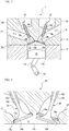
- FIG. 1 is a cross-sectional view of the internal-combustion engine 1 and mainly illustrates the configuration around the cylinder head.
- the internal-combustion engine 1 includes a cylinder block 11 and a cylinder head 12 that is mounted on the upper portion of the cylinder block 11.
- the internal-combustion engine 1 is, for example, a four-cylinder gasoline engine, and the cylinder block 11 has four cylinders 11a arranged in the depth direction of the drawing sheet.
- the cylinders 11a house respective pistons 13 that reciprocate in the vertical direction in the figure.
- Each piston 13 is connected to a crankshaft 14, which extends in the depth direction of the drawing sheet, via a connecting rod 13a.
- the cylinder head 12 has a mounting surface 12a for being mounted to the cylinder block 11.
- the mounting surface 12a is provided with four recesses 12b at positions corresponding to respective cylinders 11a.
- the recesses 12b define combustion chambers 15 of the cylinders.
- Each combustion chamber 15 is a space for combusting a mixture gas of fuel and intake air and is defined by a recess 12b of the cylinder head 12, a top surface 13b of the piston 13, and an inner circumferential surface of the cylinder 11a.
- the cylinder head 12 includes ports for intake (referred to as intake ports, hereinafter) 16 that connect between the combustion chambers 15 and one side surface 12c of the cylinder head 12.
- the intake ports 16 have a curved, approximately cylindrical shape and supply intake air from an intake manifold (not illustrated) connected to the side surface 12c into respective combustion chambers 15.
- the cylinder head 12 further includes ports for exhaust (referred to as exhaust ports, hereinafter) 17 that connect between the combustion chambers 15 and the other side surface 12d of the cylinder head 12.
- the exhaust ports 17 have a curved, approximately cylindrical shape like the intake ports 16 and exhaust the exhaust gas generated by the combustion of the mixture gas in respective combustion chambers 15 to an exhaust manifold (not illustrated) connected to the side surface 12d.
- one cylinder 11a is provided with two intake ports 16 and two exhaust ports 17.
- the cylinder head 12 is provided with intake valves 18 that open and close the intake ports 16 with respect to the combustion chambers 15 and exhaust valves 19 that open and close the exhaust ports 17 with respect to the combustion chambers 15.
- Each intake valve 18 includes a round rod-shaped valve stem 18a and a disk-shaped valve head 18b that is provided at the tip of the valve stem 18a.
- each exhaust valve 19 includes a round rod-shaped valve stem 19a and a disk-shaped valve head 19b that is provided at the tip of the valve stem 19a.
- the valve stems 18a and 19a are slidably inserted into approximately cylindrical valve guides 18c and 19c, respectively. This allows the intake valves 18 and the exhaust valves 19 to be movable with respect to the combustion chambers 15 along the axial directions of the valve stems 18a and 19a.
- FIG. 2 is an enlarged view illustrating a portion in which a combustion chamber 15 communicates with an intake port 16 and an exhaust port 17.
- the intake port 16 includes an approximately circular opening portion 16a at the portion communicating with the combustion chamber 15.
- the opening portion 16a has an annular edge portion provided with an annular valve seat film 16b that abuts against the valve head 18b of an intake valve 18.
- the intake valve 18 moves upward along the axial direction of the valve stem 18a, the upper surface of the valve head 18b comes into contact with the valve seat film 16b to close the intake port 16.
- a gap is formed between the upper surface of the valve head 18b and the valve seat film 16b to open the intake port 16.
- the exhaust port 17 includes an approximately circular opening portion 17a at the portion communicating with the combustion chamber 15, and the opening portion 17a has an annular edge portion provided with an annular valve seat film 17b that abuts against the valve head 19b of an exhaust valve 19.
- the exhaust valve 19 moves upward along the axial direction of the valve stem 19a, the upper surface of the valve head 19b comes into contact with the valve seat film 17b to close the exhaust port 17.
- the exhaust valve 19 moves downward along the axial direction of the valve stem 19a, a gap is formed between the upper surface of the valve head 19b and the valve seat film 17b to open the exhaust port 17.
- the intake valve 18 opens when the corresponding piston 13 moves down, and the mixture gas is introduced from the intake port 16 into the cylinder 11a. Subsequently, in a state in which the intake valve 18 and the exhaust valve 19 are closed, the piston 13 moves up to compress the mixture gas in the cylinder 11a, and when the piston 13 approximately reaches the top dead center, the mixture gas is ignited to explode by a spark plug, which is not illustrated. This explosion makes the piston 13 move down to the bottom dead center and is converted into the rotational force via the connected crankshaft 14. When the piston 13 reaches the bottom dead center and starts moving up again, only the exhaust valve 19 is opened to exhaust the exhaust gas in the cylinder 11a to the exhaust port 17. The internal-combustion engine 1 repeats the above cycle to generate the output.
- the opening portions 16a and 17a of the cylinder head 12 have respective annular edge portions, and the valve seat films 16b and 17b are formed directly on the annular edge portions using a cold spray method.
- the cold spray method refers to a method that includes making a supersonic flow of an operation gas having a temperature lower than the melting point or softening point of a raw material powder, injecting the raw material powder carried by a carrier gas into the operation gas to spray the raw material powder from a nozzle tip, and causing the raw material powder in the solid phase state to collide with a base material to form a metal film by plastic deformation of the raw material powder.
- the cold spray method Compared with a thermal spray method in which the material is melted and deposited on a base material, the cold spray method has features that a dense film can be obtained without oxidation in the air, thermal alteration is suppressed because of less thermal effect on the material particles, the film formation speed is high, the film can be made thick, and the deposition efficiency is high.
- the cold spray method is suitable for use for structural materials such as the valve seat films 16b and 17b of the internal-combustion engine 1 because the film formation speed is high and the films can be made thick.
- FIG. 3 illustrates the schematic configuration of a cold spray apparatus 2 according to one or more embodiments of the present invention.
- the cold spray apparatus 2 is used for the formation of the above valve seat films 16b and 17b.
- Conventional cold spray apparatuses are used for repair and the like of metal mechanical components and structural components and are thus often used for film formation on a relatively large area.
- the cold spray apparatus 2 according to one or more embodiments of the present invention is applied to film formation on a site having a relatively small area, such as the valve seat films 16b and 17b of the cylinder head 12, and therefore includes a nozzle for cold spray that is reduced in size than those of the conventional cold spray apparatuses.
- the cold spray apparatus 2 includes a gas supply unit 21 that supplies an operation gas and a carrier gas, a raw material powder supply unit 22 that supplies a raw material powder of the valve seat films 16b and 17b, and a cold spray gun 23 that sprays the raw material powder as a supersonic flow using the operation gas having a temperature equal to or lower than the melting point of the raw material powder.
- the gas supply unit 21, the raw material powder supply unit 22, and the cold spray gun 23 correspond to the gas supply means, the raw material powder supply means, and the spray means according to the present invention.
- the gas supply unit 21 includes a compressed gas cylinder 21a, an operation gas line 21b, and a carrier gas line 21c.
- Each of the operation gas line 21b and the carrier gas line 21c includes a pressure regulator 21d, a flow rate control valve 21e, a flow meter 21f, and a pressure gauge 21g.
- the pressure regulators 21d, the flow rate control valves 21e, the flow meters 21f, and the pressure gauges 21g are used for adjusting the pressure and flow rate of the operation gas and carrier gas from the compressed gas cylinder 21a.
- the operation gas line 21b is installed with a heater 21i heated by a power source 21h.
- the operation gas is heated by the heater 21i to a temperature lower than the melting point or softening point of the raw material powder and then introduced into a chamber 23a of the cold spray gun 23.
- the chamber 23a is installed with a pressure gauge 23b and a thermometer 23c, which are used for feedback control of the pressure and temperature.
- the raw material powder supply unit 22 includes a raw material powder supply device 22a, which is provided with a weighing machine 22b and a raw material powder supply line 22c.
- the carrier gas from the compressed gas cylinder 21a is introduced into the raw material powder supply device 22a through the carrier gas line 21c.
- a predetermined amount of the raw material powder weighed by the weighing machine 22b is carried into the chamber 23a via the raw material powder supply line 22c.
- the cold spray gun 23 includes a nozzle for cold spray 25 according to one or more embodiments of the present invention at the tip portion of the cold spray gun 23.
- the cold spray gun 23 sprays the raw material powder P, which is carried into the chamber 23a by the carrier gas, together with the operation gas as the supersonic flow from the tip of the nozzle for cold spray 25 and causes the raw material powder P in the solid phase state or solid-liquid coexisting state to collide with a base material 24 to form a film 24a.
- the cylinder head 12 is applied as the base material 24, and the raw material powder P is sprayed onto the annular edge portions of the opening portions 16a and 17a of the cylinder head 12 using the cold spray method to form the valve seat films 16b and 17b.
- valve seats of the cylinder head 12 are required to have high heat resistance and wear resistance to withstand the impact input from the valves in the combustion chambers 15 and high heat conductivity for cooling the combustion chambers 15.
- the valve seats can be obtained which are excellent in the heat resistance and wear resistance and harder than the cylinder head 12 formed of an aluminum alloy for casting.
- valve seat films 16b and 17b are formed directly on the cylinder head 12, and higher heat conductivity can therefore be obtained as compared with conventional valve seats formed by press-fitting seat rings as separate components into the port opening portions. Furthermore, as compared with the case in which the seat rings as separate components are used, subsidiary effects can be obtained such as that the valve seats can be made close to a water jacket for cooling and the tumble flow can be promoted due to expansion of the throat diameter of the intake ports 16 and exhaust ports 17 and optimization of the port shape.
- the raw material powder P used for forming the valve seat films 16b and 17b is preferably a powder of metal that is harder than an aluminum alloy for casting and with which the heat resistance, wear resistance, and heat conductivity required for the valve seats can be obtained.
- the precipitation-hardened copper alloy for use may be a Corson alloy that contains nickel and silicon, chromium copper that contains chromium, zirconium copper that contains zirconium, or the like.
- a precipitation-hardened copper alloy that contains nickel, silicon, and chromium a precipitation-hardened copper alloy that contains nickel, silicon, and zirconium
- a precipitation-hardened copper alloy that contains nickel, silicon, chromium, and zirconium a precipitation-hardened copper alloy that contains chromium and zirconium, or the like.
- the valve seat films 16b and 17b may also be formed by mixing a plurality of types of raw material powders; for example, a first raw material powder and a second raw material powder.
- a first raw material powder a powder of metal that is harder than an aluminum alloy for casting and with which the heat resistance, wear resistance, and heat conductivity required for valve seats can be obtained.
- the second raw material powder a powder of metal that is harder than the first raw material powder.
- the second raw material powder for application may be an alloy such as an iron-based alloy, a cobalt-based alloy, a chromium-based alloy, a nickel-based alloy, or a molybdenum-based alloy, ceramics, or the like.
- an alloy such as an iron-based alloy, a cobalt-based alloy, a chromium-based alloy, a nickel-based alloy, or a molybdenum-based alloy, ceramics, or the like.
- One type of these metals may be used alone, or two or more types may also be used in combination.
- valve seat films formed of a mixture of the first raw material powder and the second raw material powder which is harder than the first raw material powder more excellent heat resistance and wear resistance can be obtained than those of valve seat films formed only of a precipitation-hardened copper alloy.
- the reason that such an effect is obtained appears to be because the second raw material powder allows the oxide film existing on the surface of the cylinder head 12 to be removed so that a new interface is exposed and formed to improve the interfacial adhesion between the cylinder head 12 and the metal films. Additionally or alternatively, it appears that the anchor effect due to the second raw material powder sinking into the cylinder head 12 improves the interfacial adhesion between the cylinder head 12 and the metal films.
- the nozzle for cold spray 25 will then be described.
- a conventional cold spray apparatus when the spray of the raw material powder is continued for several minutes or more, for example, the raw material powder may adhere and deposit in the nozzle for cold spray to block the inside of the nozzle for cold spray.
- the deposited material of the raw material powder removed from the inside of the nozzle for cold spray may be sprayed by the operation gas to form a part of the film.
- the deposited material of the raw material powder has a very porous structure, and the formed film therefore has a non-uniform structure.
- the reason that the raw material powder adheres inside the nozzle for cold spray is because the raw material powder collides with the inner surface of the nozzle for cold spray at high speed thereby to plastically deform the raw material powder and the nozzle for cold spray, thus breaking the oxide films of the raw material powder and the nozzle for cold spray, and the newly-formed surfaces of the raw material powder and the nozzle for cold spray come into contact with each other to form metal bond. Accordingly, in a small nozzle for cold spray used for forming a film on a site having a relatively small area, such as the above-described valve seat films 16b and 17b, the ratio of the wall surface to the nozzle internal area is relatively large, and the friction between the nozzle and the raw material powder is relatively remarkable, which increases the nozzle temperature.
- the nozzle for cold spray 25 of the present embodiment is made smaller than the conventional cold spray apparatus in order to be applied to the film formation on a site having a relatively small area.
- the nozzle for cold spray 25 has a function of cooling the nozzle for cold spray 25.
- the temperature inside the nozzle for cold spray 25 is lowered as compared with the temperature before cooling; therefore, even when the raw material powder P collides with the nozzle for cold spray 25, a sufficient amount of plastic deformation for adhesion is not obtained, and the raw material powder P is less likely to adhere.
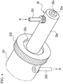
- FIG. 4 is a perspective view illustrating a state in which the nozzle for cold spray 25 of the present embodiment is attached to a nozzle attaching portion 231 of the cold spray gun 23.
- the nozzle attaching portion 231 has a cylindrical shape and holds the nozzle for cold spray 25 on the tip side of the nozzle attaching portion 231.
- the nozzle attaching portion 231 corresponds to the main body portion of the cold spray apparatus in the present invention.
- a nozzle fixing ring 232 is attached on the tip side of the nozzle attaching portion 231 to fix the nozzle for cold spray 25 to the nozzle attaching portion 231.
- the nozzle attaching portion 231 connects the nozzle for cold spray 25 and the chamber 23a of the cold spray gun 23.
- the cold spray gun 23 supplies the raw material powder P and the operation gas in the chamber 23a to the nozzle for cold spray 25 through the nozzle attaching portion 231 and sprays the raw material powder P and the operation gas from a spray port 25a provided at the tip of the nozzle for cold spray 25.
- the nozzle for cold spray 25 includes a spray portion 25b and a base portion 25c.
- the spray portion 25b has the spray port 25a for the raw material powder P at the tip of the spray portion 25b.
- the base portion 25c is attached to the nozzle attaching portion 231.
- the spray portion 25b has a cylindrical shape and projects from the tip side of the nozzle attaching portion 231.
- a spray passage 25d is provided in the spray portion 25b to accelerate the raw material powder P, which is supplied from the chamber 23a, together with the operation gas to a supersonic flow.
- the spray port 25a is provided at the end of the spray passage 25d.
- the spray portion 25b is made to have a smaller diameter than that of the conventional nozzle for cold spray.
- the base portion 25c is in a cylindrical shape having a larger diameter than that of the spray portion 25b and is attached to the nozzle attaching portion 231.
- the nozzle fixing ring 232 fixes the base portion 25c so that the nozzle for cold spray 25 does not drop off from the nozzle attaching portion 231.
- the nozzle for cold spray 25 includes a flow path 25e (see FIG. 7 ) through which a refrigerant (for example, water) R flows.
- the nozzle for cold spray 25 includes a refrigerant introduction part 251 at the upper portion of the spray portion 25b on the tip side.
- the refrigerant introduction part 251 introduces the refrigerant R into the flow path 25e.
- the lower portion of the nozzle attaching portion 231 is provided with a refrigerant discharge part 233 that discharges the refrigerant R in the flow path 25e.
- the nozzle for cold spray 25 cools the spray passage 25d of the nozzle for cold spray 25 through introducing the refrigerant R from the refrigerant introduction part 251 into the flow path 25e, allowing the refrigerant R to flow in the flow path 25e, and discharging the refrigerant R from the flow path 25e via the refrigerant discharge part 233.
- FIG. 5 is a perspective view illustrating a state in which the nozzle for cold spray 25 is detached from the nozzle attaching portion 231 of the cold spray gun 23.
- a recessed nozzle accommodating portion 231a is provided on the tip side of the nozzle attaching portion 231.
- the base portion 25c of the nozzle for cold spray 25 is inserted into the nozzle accommodating portion 231a.
- the outer peripheral surface of the nozzle attaching portion 231 on its tip side is provided with a threaded portion 231b to which the nozzle fixing ring 232 is attached.
- the nozzle attaching portion 231 includes a cylindrical nozzle connecting portion 231d at a bottom surface portion 231c of the nozzle accommodating portion 231a on the rear end side.
- the nozzle connecting portion 231d is connected to the nozzle for cold spray 25.
- the central portion of the nozzle connecting portion 231d is provided with a chamber connecting path 231e that connects the chamber 23a of the cold spray gun 23 and the nozzle for cold spray 25.
- a discharge path 231f is provided below the nozzle connecting portion 231d to connect the flow path 25e of the nozzle for cold spray 25 and the refrigerant discharge part 233.
- An O-ring 231g is incorporated in the outer periphery of the discharge path 231f to seal the connection portion between the flow path 25e of the nozzle for cold spray 25 and the discharge path 231f.
- the nozzle fixing ring 232 has a cylindrical shape and includes a nut portion 232a on the inner surface.
- the nut portion 232a is screwed with the threaded portion 231b of the nozzle attaching portion 231.
- a nozzle pressing portion 232b is provided on the tip side of the nozzle fixing ring 232.
- the nozzle pressing portion 232b is provided with a hole into which the spray portion 25b of the nozzle for cold spray 25 is inserted.
- the nozzle pressing portion 232b presses the base portion 25c of the nozzle for cold spray 25, and the rear end portion of the nozzle for cold spray 25 is pressed against the bottom surface portion 231c of the nozzle accommodating portion 231a. This allows the spray passage 25d and the chamber connecting path 231e to be connected without a gap and also allows the flow path 25e and the discharge path 231f to be connected without a gap.
- the refrigerant introduction part 251, which introduces the refrigerant R into the flow path 25e of the nozzle for cold spray 25, includes an introduction pipe connecting portion 251a provided on the spray portion 25b of the nozzle for cold spray 25, an introduction pipe 251b connected to the introduction pipe connecting portion 251a, and a fixing nut 251c that fixes the introduction pipe 251b to the introduction pipe connecting portion 251a.
- the introduction pipe connecting portion 251a includes a cylindrical pipe insertion part 251d inserted into the introduction pipe 251b, which is made of a steel pipe, a hose, or the like, and a fixing screw 251e provided below the pipe insertion part 251d.
- the inner diameter portion of the pipe insertion part 251d penetrates into the nozzle for cold spray 25 and is connected to the flow path 25e.
- the fixing nut 251c is screwed with the fixing screw 251e of the introduction pipe connecting portion 251a, and the outer periphery of the introduction pipe 251b, into which the pipe insertion part 251d is inserted, is pressed and fixed by a pipe insertion hole 251f.
- the introduction pipe 251b is connected to a refrigerant circulation circuit 27 (see FIG. 3 ) that circulates the refrigerant R between the refrigerant introduction part 251 and the refrigerant discharge part 233, and the refrigerant R is introduced into the introduction pipe 251b from the refrigerant circulation circuit 27.
- the refrigerant discharge part 233 which discharges the refrigerant R from the flow path 25e of the nozzle for cold spray 25, includes a discharge pipe connecting portion 233a provided on the nozzle attaching portion 231, a discharge pipe 233b connected to the discharge pipe connecting portion 233a, and a fixing nut 233c that fixes the discharge pipe 233b to the discharge pipe connecting portion 233a.
- the discharge pipe connecting portion 233a includes a cylindrical pipe insertion part 233d inserted into the discharge pipe 233b, which is made of a steel pipe, a hose, or the like, and a fixing screw 233e provided above the pipe insertion part 233d.
- the inner diameter portion of the pipe insertion part 233d is connected to the discharge path 231f arranged in the bottom surface portion 231c of the nozzle attaching portion 231.
- the fixing nut 233c is screwed with the fixing screw 233e of the discharge pipe connecting portion 233a, and the outer periphery of the discharge pipe 233b, into which the pipe insertion part 233d is inserted, is pressed and fixed by a pipe insertion hole 233f.
- the discharge pipe 233b is connected to the refrigerant circulation circuit 27, and the refrigerant R is discharged from the discharge pipe 233b to the refrigerant circulation circuit 27.
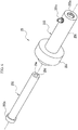
- FIG. 6 is an exploded perspective view illustrating the configuration of the nozzle for cold spray 25.
- the nozzle for cold spray 25 includes a nozzle main body 252 having the spray port 25a and the spray passage 25d and a cooling jacket 253 having the spray portion 25b and the base portion 25c.
- the nozzle main body 252 is inserted into the cooling jacket 253 from the rear end side of the cooling jacket 253, and the tip portion having the spray port 25a protrudes from the tip of the cooling jacket 253.
- the nozzle main body 252 has an elongated cylindrical shape and includes the spray passage 25d inside.
- the nozzle main body 252 includes a connecting portion 252a at the rear end portion on the opposite side to the spray port 25a.
- the connecting portion 252a has a diameter larger than that of the other portions.
- the connecting portion 252a of the nozzle main body 252 comes into contact with the nozzle connecting portion 231d thereby to connect the spray passage 25d and the chamber connecting path 231e.
- the nozzle main body 252 is made of a material having heat conductivity; for example, a metal such as stainless steel. This allows the inner spray passage 25d to be cooled by cooling the outer peripheral surface of the nozzle main body 252 with the refrigerant R.
- the cooling jacket 253 includes the introduction pipe connecting portion 251a at the upper portion of the spray portion 25b on the tip side.
- the cooling jacket 253 also includes an inner diameter portion 253a into which the nozzle main body 252 can be inserted.
- the cooling jacket 253 surrounds the nozzle main body 252, which is inserted from the rear end side, to form the flow path 25e for the refrigerant R between the cooling jacket 253 and the outer peripheral surface of the nozzle main body 252.
- FIG. 7 is a cross-sectional view in which the nozzle for cold spray 25 attached to the nozzle attaching portion 231 of the cold spray gun 23 is cut along the spraying direction of the raw material powder P.
- the spray passage 25d of the nozzle main body 252 is provided with a convergent portion 252b, a throat portion 252c, and a divergent portion 252d in this order from the rear end side.
- the convergent portion 252b is a conical passage whose cross-sectional area is gradually reduced toward the tip.
- the divergent portion 252d is a conical passage whose cross-sectional area is gradually increased toward the tip.
- the throat portion 252c is a connecting portion between the convergent portion 252b and the divergent portion 252d and has the smallest cross-sectional area in the nozzle main body 252.
- the nozzle main body 252 sprays the raw material powder P as a supersonic flow from the spray port 25a through compressing the operation gas, which is supplied together with the raw material powder P from the chamber 23a, in the convergent portion 252b and releasing the pressure of the operation gas in the divergent portion 252d.
- the inner diameter portion 253a of the cooling jacket 253 has an inner diameter larger than the outer diameter of the nozzle main body 252.
- the cooling jacket 253 therefore surrounds the nozzle main body 252, which is inserted from the rear end side, to form a gap between the inner diameter portion 253a and the nozzle main body 252.
- the gap serves as the flow path 25e for the refrigerant R.
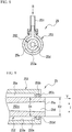
- the flow path 25e is provided so as to extend from the tip side to the rear end side of the nozzle main body 252. As illustrated in the cross-sectional view of FIG. 8 along the line VIII-VIII of FIG. 7 , the flow path 25e is provided so as to surround the entire circumference of the nozzle main body 252.
- a seal retaining portion 253c is provided on the tip side of the inner diameter portion 253a of the cooling jacket 253.
- the seal retaining portion 253c retains an O-ring 253b.
- the O-ring 253b which corresponds to the seal member of the present invention, is in close contact with the outer peripheral surface of the nozzle main body 252 to seal the flow path 25e.
- the seal retaining portion 253c includes a front wall 253d and a rear wall 253e that are annularly projected from the inner surface of the inner diameter portion 253a of the cooling jacket 253 toward the central axis of the cooling jacket 253.
- the O-ring 253b is retained in an annular groove provided between the front wall 253d and the rear wall 253e.
- the nozzle main body 252 receives force that acts in the spraying direction of the raw material powder P due to the frictional force between the spray passage 25d and the operation gas which sprays the raw material powder P.
- the nozzle main body 252 therefore vibrates along the arrow V direction in FIG. 9 .
- the cold spray gun 23 moves and stops moving in order to direct the nozzle for cold spray 25 to the film formation position.
- the tip portion of the nozzle main body 252 is misaligned in the I direction approximately orthogonal to the central axis of the nozzle main body 252 due to the inertial force caused when the cold spray gun 23 moves and stops moving.
- the front wall 253d and rear wall 253e of the seal retaining portion 253c are joined with the outer peripheral surface of the nozzle main body 252 in a socket-and-spigot joint fashion.
- the socket-and-spigot joint refers to a joint in which two members, such as represented by a recessed portion and a projected portion, are fitted without a gap thereby to ensure their relative positions so that no play occurs after the fitting.
- the outer diameter D1 of the nozzle main body 252 is, for example, ⁇ 11.2 mm, and the outer diameter tolerance is the minimum +0.02 to +0.04 mm.
- the inner diameter D2 of the front wall 253d and rear wall 253e of the seal retaining portion 253c, which is joined with the nozzle main body 252 in the socket-and-spigot joint fashion is, for example, ⁇ 11.3 mm, and the inner diameter tolerance is, for example, -0.01 to -0.03 mm.
- the socket-and-spigot joint with such dimensions and tolerances allows the gap generated between the nozzle main body 252 and the seal retaining portion 253c to be very small, such as 0.015 to 0.035 mm.
- the nozzle main body 252 and the seal retaining portion 253c can therefore be joined with no play after the fitting while ensuring their relative positions.
- the nozzle main body 252 and the seal retaining portion 253c are joined in the socket-and-spigot joint fashion; therefore, when the nozzle main body 252 is blocked and needs to be replaced, or when the O-ring 253b of the seal retaining portion 253c deteriorates and needs to be replaced, for example, the nozzle for cold spray 25 can be disassembled to detach the nozzle main body 252 from the cooling jacket 253.
- the above-described dimensions and tolerances of the nozzle main body 252 and the seal retaining portion 253c are merely examples, and it is preferred to appropriately set the tolerances for the socket-and-spigot joint in accordance with the dimensions of the nozzle main body 252 and the seal retaining portion 253c.
- the nozzle main body and the cooling jacket may be joined using interference fit instead of the socket-and-spigot joint.
- the interference fit refers to a joint in which two members, such as represented by a recessed portion and a projected portion, are designed with a slightly larger size of the projected portion than the size of the recessed portion and the projected portion is pressed into and fitted with the recessed part thereby to ensure their relative positions so that no play occurs after the fitting.
- the outer diameter D1 of the nozzle main body 252 is made slightly larger than the inner diameter D2 of the front wall 253d and rear wall 253e of the seal retaining portion 253c, and the nozzle main body 252 is pressed into and fitted with the seal retaining portion 253c.
- the nozzle main body 252 and the seal retaining portion 253c can be joined with no play after the fitting while ensuring their relative positions.
- the cooling jacket 253 also includes a seal retaining portion 253g that retains an O-ring 253f on the rear end side of the inner diameter portion 253a.
- the rear end side of the nozzle main body 252 is supported so that the connecting portion 252a is interposed between the cooling jacket 253 and the nozzle attaching portion 231, and the vibration and misalignment occurring on the rear end side are very small as compared with those occurring on the tip side of the nozzle main body 252.
- the seal retaining portion 253g of the cooling jacket 253 on the rear end side is not joined with the nozzle main body 252 in a socket-and-spigot joint fashion.
- the base portion 25c of the cooling jacket 253 is provided with a discharge connection path 253h that connects the flow path 25e to the discharge path 231f of the nozzle attaching portion 231.
- the refrigerant circulation circuit 27 which circulates the refrigerant R into the flow path 25e of the nozzle for cold spray 25 will then be described with reference to FIG. 3 .
- the refrigerant circulation circuit 27 includes the above described introduction pipe 251b and discharge pipe 233b, a tank 271 that stores the refrigerant R, a pump 272 that is connected to the introduction pipe 251b and flows the refrigerant R between the tank 271 and the nozzle for cold spray 25, and a cooler 273 that cools the refrigerant R.
- the cooler 273, which is composed of a heat exchanger or the like, for example, cools the refrigerant R having a raised temperature after cooling the nozzle main body 252 by exchanging heat between the refrigerant R and a cooling medium such as air, water, or gas.
- the refrigerant circulation circuit 27 sucks the refrigerant R in the tank 271 using the pump 272 and supplies the refrigerant R to the refrigerant introduction part 251 via the cooler 273.
- the refrigerant R supplied to the refrigerant introduction part 251 flows through the flow path 25e in the nozzle for cold spray 25 from the tip side to the rear end side, and during that time, exchanges heat with the nozzle main body 252 to cool it.
- the refrigerant R having flowed to the rear end side of the flow path 25e is discharged into the discharge pipe 233b via the refrigerant discharge part 233 and returns to the tank 271.
- the refrigerant circulation circuit 27 cools the nozzle main body 252 by circulating the refrigerant R while cooling it, and it is therefore possible to suppress the adhesion of the raw material powder P to the spray passage 25d of the nozzle main body 252.
- FIG. 10 is a process chart illustrating the processing steps for the valve sites in the method for manufacturing the cylinder head 12 of the present embodiment.
- the method for manufacturing the cylinder head 12 of the present embodiment includes a casting step (step SI), a cutting step (step S2), a coating step (step S3), and a finishing step (step S4). Processing steps other than those for the valve sites will be omitted for simplicity of the description.
- an aluminum alloy for casting is poured into a mold in which sand cores are set, and a semimanufactured cylinder head having intake ports 16 and exhaust ports 17 formed in the main body is cast-molded.
- the intake ports 16 and the exhaust ports 17 are formed by the sand cores, and the recesses 12b are formed by the mold.
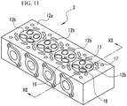
- FIG. 11 is a perspective view of a semimanufactured cylinder head 3 having been cast-molded in the casting step S1 as seen from above the mounting surface 12a which is to be mounted to the cylinder block 11.
- the semimanufactured cylinder head 3 includes four recesses 12b, two intake ports 16 and two exhaust ports 17 provided in each recess 12b, etc.
- the two intake ports 16 and two exhaust ports 17 of each recess 12b are merged into respective ones in the semimanufactured cylinder head 3, which communicate with openings provided on both side surfaces of the semimanufactured cylinder head 3.
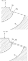
- FIG. 12A is a cross-sectional view of the semimanufactured cylinder head 3 taken along line XII-XII of FIG. 11 and illustrates an intake port 16.
- the intake port 16 is provided with a circular opening portion 16a that is exposed in the recess 12b of the semimanufactured cylinder head 3.
- the subsequent cutting step S2 milling work is performed on the semimanufactured cylinder head 3 as illustrated in FIG. 12B , such as using an end mill or a ball end mill, to form an annular valve seat portion 16c around the opening portion 16a of the intake port 16.
- the annular valve seat portion 16c is an annular groove that serves as the base shape of a valve seat film 16b, and is formed on the outer circumference of the opening portion 16a.
- the raw material powder P is sprayed onto the annular valve seat portion 16c using the cold spray method to form a film, and the valve seat film 16b is formed based on the film.
- the annular valve seat portion 16c is therefore formed with a size slightly larger than the valve seat film 16b.
- the raw material powder P is sprayed onto the annular valve seat portion 16c of the semimanufactured cylinder head 3 using the cold spray apparatus 2 of the present embodiment to form the valve seat film 16b. More specifically, in the coating step S3, the semimanufactured cylinder head 3 and the nozzle for cold spray 25 are relatively moved at a constant speed so that the raw material powder P is sprayed onto the entire circumference of the annular valve seat portion 16c while keeping constant the posture of the annular valve seat portion 16c and the nozzle for cold spray 25 of the cold spray gun 23 and the distance between the annular valve seat portion 16c and the nozzle for cold spray 25.
- the semimanufactured cylinder head 3 is moved with respect to the nozzle for cold spray 25 of the cold spray gun 23, which is fixedly arranged, using a work rotating apparatus 4 illustrated in FIG. 13 .
- the work rotating apparatus 4 includes a work table 41, a tilt stage unit 42, an XY stage unit 43, and a rotation stage unit 44.
- the work table 41 holds the semimanufactured cylinder head 3.
- the tilt stage unit 42 is a stage that supports the work table 41 and rotates the work table 41 around an A-axis arranged in the horizontal direction to tilt the semimanufactured cylinder head 3.
- the XY stage unit 43 includes a Y-axis stage 43a that supports the tilt stage unit 42 and an X-axis stage 43b that supports the Y-axis stage 43a.
- the Y-axis stage 43a moves the tilt stage unit 42 along the Y-axis arranged in the horizontal direction.
- the X-axis stage 43b moves the Y-axis stage 43a along the X-axis orthogonal to the Y-axis on the horizontal plane.
- the rotation stage unit 44 has a rotation table 44a that supports the XY stage unit 43 on the upper surface, and rotates the rotation table 44a thereby to rotate the semimanufactured cylinder head 3 around the Z-axis in an approximately vertical direction.
- the tip of the nozzle for cold spray 25 of the cold spray gun 23 is fixedly arranged above the tilt stage unit 42 and in the vicinity of the Z-axis of the rotation stage unit 44.
- the work rotating apparatus 4 uses the tilt stage unit 42 to tilt the work table 41 so that, as illustrated in FIG. 14 , the central axis C of the intake port 16 to be formed with the valve seat film 16b becomes vertical.
- the work rotating apparatus 4 also uses the XY stage unit 43 to move the semimanufactured cylinder head 3 so that the central axis C of the intake port 16 to be formed with the valve seat film 16b coincides with the Z-axis of the rotation stage unit 44.
- the rotation stage unit 44 rotates the semimanufactured cylinder head 3 around the Z-axis while the nozzle for cold spray 25 sprays the raw material powder P onto the annular valve seat portion 16c, thereby forming a film on the entire circumference of the annular valve seat portion 16c.
- the nozzle for cold spray 25 introduces the refrigerant R supplied from the refrigerant supply unit into the flow path 25e via the refrigerant introduction part 251.
- the refrigerant R cools the nozzle main body 252 while flowing from the tip side toward the rear end side of the flow path 25e.
- the refrigerant R having flowed to the rear end side of the flow path 25e is discharged from the flow path 25e via the refrigerant discharge part 233 and recovered by the refrigerant recovery unit.
- the nozzle main body 252 vibrates along the spraying direction of the raw material powder P, that is, along the arrow V direction of FIG. 9 due to the friction between the spray passage 25d and the operation gas which sprays the raw material powder P. Additionally or alternatively, the tip portion of the nozzle main body 252 is misaligned in the direction approximately orthogonal to the central axis of the nozzle main body 252, that is, in the I direction of FIG. 9 due to the inertial force caused when the nozzle for cold spray 25 moves and stops moving.
- the vibration in the V direction and the misalignment in the I direction of the nozzle main body 252 is suppressed by the socket-and-spigot joint between the outer peripheral surface of the nozzle main body 252 and the seal retaining portion 253c of the cooling jacket 253.
- the work rotating apparatus 4 temporarily stops the rotation of the rotation stage unit 44 when the semimanufactured cylinder head 3 makes one rotation around the Z-axis to complete the formation of the valve seat film 16b. While the rotation is stopped, the XY stage unit 43 moves the semimanufactured cylinder head 3 so that the central axis C of the intake port 16 to be subsequently formed with the valve seat film 16b coincides with the Z-axis of the rotation stage unit 44. After the XY stage unit 43 completes the movement of the semimanufactured cylinder head 3, the work rotating apparatus 4 restarts the rotation of the rotation stage unit 44 to form the valve seat film 16b for the next intake port 16.
- finishing work is performed on the valve seat films 16b and 17b, the intake ports 16, and the exhaust ports 17.
- the surfaces of the valve seat films 16b and 17b are cut by milling work using a ball end mill to adjust the valve seat films 16b into a predetermined shape.
- a ball end mill is inserted from the opening portion 16a into each intake port 16 to cut the inner surface of the intake port 16 on the opening port 16a side along a working line PL illustrated in FIG. 15A .
- the working line PL defines a range in which the raw material powder P scatters and adheres in the intake port 16 to form a relatively thick excessive film SF. More specifically, the working line PL refers to a range in which the excessive film SF is formed thick to such an extent that affects the intake performance of the intake port 16.
- FIG. 15B illustrates the intake port 16 after the finishing step S4.
- each exhaust port 17 is formed with the valve seat film 17b through the formation of a small-diameter portion in the exhaust port 17 by the cast molding, the formation of an annular valve seat portion by the cutting work, the cold spraying onto the annular valve seat portion, and the finishing work. Detailed description will therefore be omitted for the procedure of forming the valve seat films 17b on the exhaust ports 17.
- the outer peripheral surface of the nozzle main body 252 and the seal retaining portion 253c of the cooling jacket 253 are joined in a socket-and-spigot joint fashion so as not to form a gap, and it is therefore possible to suppress the vibration in the spraying direction of the raw material powder P (V direction of FIG. 9 ) and the misalignment in the direction approximately orthogonal to the central axis of the nozzle main body 252 (I direction of FIG. 9 ) which occur in the nozzle main body 252.
- the socket-and-spigot joint between the outer peripheral surface of the nozzle main body 252 and the seal retaining portion 253c does not cause a gap at the seal retaining portion 253c, and it is therefore possible to prevent the refrigerant R from leaking from the flow path 25e of the nozzle for cold spray 25.
- the flow rate of the raw material powder P and the operation gas becomes high on the tip side of the nozzle main body 252, and the friction between the spray passage 25d and the raw material powder P and operation gas becomes large; therefore, the temperature on the tip side of the nozzle main body 252 is higher than that on the rear end side. Accordingly, the raw material powder P is more likely to adhere to the nozzle main body 252 on the tip side than on the rear end side.
- the cold spray apparatus 2 and the nozzle for cold spray 25 of the present embodiment introduce the refrigerant R from the tip side of the nozzle main body 252 into the flow path 25e via the refrigerant introduction part 251 provided on the tip side of the nozzle for cold spray 25, and the tip side of the nozzle main body 252 can therefore be effectively cooled using the refrigerant R which does not undergo the temperature rise due to the heat exchange with the nozzle main body 252. It is thus possible to suppress the adhesion and deposition of the raw material powder P to the spray passage 25d of the nozzle main body 252.
- the cooling jacket 253 is attached to the nozzle attaching portion 231 which is the main body portion of the cold spray apparatus 2, and the nozzle main body 252 is supported so that the connecting portion 252a on the rear end side is interposed between the cooling jacket 253 and the nozzle attaching portion 231. That is, the cooling jacket 253 is not attached to the nozzle main body 252.
- the cooling jacket 253 is not affected by the vibration and misalignment of the nozzle main body 252.
- the nozzle for cold spray 25 of the present embodiment can therefore effectively suppress the vibration and misalignment of the nozzle main body 252 owing to the cooling jacket 253.
- the flow path 25e for the refrigerant R is provided so as to extend from the tip side to the rear end side of the nozzle main body 252 and surround the entire circumference of the nozzle main body 252, and the nozzle main body 252 as a whole can therefore be cooled from the outside. It is thus possible to suppress the adhesion and deposition of the raw material powder P to the spray passage 25d of the nozzle main body 252.
- the nozzle for cold spray according to a second embodiment of the present invention will then be described.
- This embodiment is different from the first embodiment in a form of the socket-and-spigot joint portion between the nozzle main body and the seal retaining portion of the cooling jacket, but other configurations are the same as those in the first embodiment, so the detailed description of the same configurations as those in the first embodiment will be omitted with the use of the same reference numerals.
- FIG. 16 is an exploded perspective view illustrating the configuration of a nozzle for cold spray 26 according to the present embodiment.
- the nozzle for cold spray 26 includes a nozzle main body 261 and a cooling jacket 262.
- the outer peripheral surface of the nozzle main body 261 on the tip side is formed with a tapered portion 261a that gradually tapers in the spraying direction of the raw material powder P. That is, the diameter of the tapered portion 261a gradually decreases in the spraying direction of the raw material powder P.
- the tapered portion 261a corresponds to the portion of the nozzle main body to be joined with the seal retaining portion in the present invention.
- FIG. 17 illustrates the tip portion of the nozzle for cold spray 26 in the cross-sectional view in which the nozzle for cold spray 26 is cut in the spraying direction of the raw material powder P.
- a seal retaining portion 262c is provided on the tip side of an inner diameter portion 262a of the cooling jacket 262.
- the seal retaining portion 262c retains an O-ring 262b.
- the O-ring 262b which corresponds to the seal member of the present invention, is in close contact with the tapered portion 261a of the nozzle main body 261 to seal the flow path 25e.
- the seal retaining portion 262c includes a front wall 262d and a rear wall 262e that are annularly projected from the inner surface of the inner diameter portion 262a of the cooling jacket 262 toward the central axis of the cooling jacket 262.
- the O-ring 262b is retained in an annular groove provided between the front wall 262d and the rear wall 262e.
- the front wall 262d and rear wall 262e of the seal retaining portion 262c correspond to the joint part of the seal retaining portion of the present invention.
- the front wall 262d and rear wall 262e of the seal retaining portion 262c are joined with the tapered portion 261a of the nozzle main body 261 in a socket-and-spigot joint fashion. That is, the front wall 262d and rear wall 262e of the seal retaining portion 262c have tapered shapes along the tapered portion 261a of the nozzle main body 261, and the seal retaining portion 262c of the cooling jacket 262 and the tapered portion 261a of the nozzle main body 261 are therefore fitted without a gap thereby to ensure their relative positions so that no play occurs after the fitting.
- the length L1 of the tapered portion 261a may be 10 mm
- the outer diameter D1a of the large-diameter part of the tapered portion 261a may be ⁇ 11.2 mm
- the outer diameter D1b of the small-diameter part of the tapered portion 261a may be ⁇ 10.2 mm.
- the outer diameter tolerance of the outer diameters D1a and D1b may be +0.02 to +0.04 mm.
- the length L2 may be 5 mm
- the inner diameter D2a of the large-diameter part may be ⁇ 11.2 mm
- the inner diameter D2b of the small-diameter part may be ⁇ 10.7 mm.
- the inner diameter tolerance of the inner diameter D2a may be -0.01 to -0.03 mm
- the inner diameter tolerance of the inner diameter D2b may be +0.02 to +0.04 mm.
- the socket-and-spigot joint with such dimensions and tolerances allows the gap generated between the nozzle main body 261 and the seal retaining portion 262c to be very small, such as several dozen ⁇ m.
- the nozzle main body 261 and the seal retaining portion 262c can therefore be joined with no play after the fitting while ensuring their relative positions.
- the nozzle main body 261 is formed with the tapered portion 261a which gradually tapers in the spraying direction of the raw material powder P, and the seal retaining portion 262c of the cooling jacket 262 has a tapered shape along the tapered portion 261a of the nozzle main body 261; therefore, when vibration in the spraying direction of the raw material powder P (V direction of FIG. 17 ) occurs in the nozzle main body 261, the socket-and-spigot joint between the tapered portion 261a and the seal retaining portion 262c is more tightened.
- the nozzle for cold spray 26 of the present embodiment can prevent the refrigerant R from leaking from the flow path 25e.
- the tapered portion 261a of the nozzle main body 261 and the seal retaining portion 262c of the cooling jacket 262 are joined in a socket-and-spigot joint fashion so as not to form a gap, and it is therefore possible to suppress the vibration in the V direction and the misalignment in the direction approximately orthogonal to the central axis of the nozzle main body 261 (I direction of FIG. 17 ) which occur in the nozzle main body 261.
- the socket-and-spigot joint between the outer peripheral surface of the nozzle main body 261 and the seal retaining portion 262c does not cause a gap at the seal retaining portion 262c, and it is therefore possible to prevent the refrigerant R from leaking from the flow path 25e of the nozzle for cold spray 26.
- the nozzle main body 252 and the seal retaining portion 253g of the cooling jacket 253 on the rear end side are not joined in a socket-and-spigot joint fashion, but if there is a concern that the refrigerant R may leak from this portion, the nozzle main body 252 and the seal retaining portion 253g may be joined in a socket-and-spigot joint fashion.
- the first embodiment has been described for an example of the small nozzle for cold spray 25 suitable for the film formation on a site having a relatively small area, such as the valve seat films 16b and 17b of the cylinder head 12, but the present invention can also be applied to a nozzle for cold spray that is used for repair and the like of metal mechanical components and structural components and thus used for the film formation on a relatively large area.
- water has been described as an example of the refrigerant R, but a liquid other than water or a gaseous matter such as a gas may also be used as the refrigerant.
Landscapes
- Chemical & Material Sciences (AREA)
- Engineering & Computer Science (AREA)
- Mechanical Engineering (AREA)
- Chemical Kinetics & Catalysis (AREA)
- Materials Engineering (AREA)
- Metallurgy (AREA)
- Organic Chemistry (AREA)
- General Engineering & Computer Science (AREA)
- Nozzles (AREA)
- Other Surface Treatments For Metallic Materials (AREA)
Abstract
Description
- The present invention relates to a nozzle for cold spray and a cold spray apparatus.
- A cold spray apparatus is known, which sprays metal particles onto a base material to form a metal film by plastic deformation of the metal particles. A nozzle for cold spray including a tubular nozzle main body and a cooling member capable of cooling the nozzle main body is also known as the nozzle used for the cold spray apparatus to spray the metal particles (see Patent Document 1, for example).
- This nozzle for cold spray cools the inner surface of the nozzle body main by cooling the outer surface of the nozzle main body, which is made of a heat conductive material, with a fluid circulated in the cooling member. This suppresses the adhesion of metal particles in the nozzle main body and prevents the nozzle main body from being blocked due to the adhesion and deposition of the metal particles.
- [Patent Document 1]
JP2009-000632A - Unfortunately, however, the above nozzle for cold spray has a problem that the fluid used as a refrigerant leaks from the cooling member. For example, when water is used as the fluid and the water leaks from the nozzle for cold spray and adheres to the metal film, this causes poor quality, poor interfacial adhesion, and the like of the metal film. This fluid leakage occurs due to a gap being created in the seal for a passage through which the fluid flows, such as by the vibration of the nozzle main body in association with the spray of metal particles or the misalignment of the nozzle main body due to movement and stop of movement of the nozzle for cold spray.
- A problem to be solved by the present invention is to provide a nozzle for cold spray and a cold spray apparatus that are able to prevent the leakage of refrigerant, such as due to the vibration or misalignment of the nozzle main body.
- The present invention solves the above problem through configuring a nozzle for cold spray so as to include a tubular nozzle main body and a cooling jacket that surrounds the nozzle main body to form a flow path for a refrigerant, providing the cooling jacket with a seal retaining portion that retains a seal member for the flow path, and joining the seal retaining portion with the nozzle main body in a socket-and-spigot joint fashion.
- According to the present invention, the socket-and-spigot joint between the nozzle main body and the cooling jacket can suppress the vibration, misalignment, and the like of the nozzle main body, thus preventing the leakage of the refrigerant.
-
-
FIG. 1 is a cross-sectional view of an internal-combustion engine including a cylinder head in which valve seat films are formed using the cold spray apparatus and the nozzle for cold spray according to one or more embodiments of the present invention. -
FIG. 2 is a cross-sectional view of the periphery of valves of the internal-combustion engine including the cylinder head in which the valve seat films are formed using the cold spray apparatus and the nozzle for cold spray according to one or more embodiments of the present invention. -
FIG. 3 is a schematic view illustrating the configuration of the cold spray apparatus according to one or more embodiments of the present invention. -
FIG. 4 is a perspective view illustrating the nozzle for cold spray according to a first embodiment of the present invention. -
FIG. 5 is a perspective view illustrating a state in which the nozzle for cold spray according to the first embodiment of the present invention is detached from a cold spray gun. -
FIG. 6 is an exploded perspective view illustrating the configuration of the nozzle for cold spray according to the first embodiment of the present invention. -
FIG. 7 is a cross-sectional view in which the nozzle for cold spray according to the first embodiment of the present invention is cut along the spraying direction of a raw material powder. -
FIG. 8 is a cross-sectional view of the nozzle for cold spray along line VIII-VIII ofFIG. 7 . -
FIG. 9 is an enlarged cross-sectional view illustrating a socket-and-spigot joint portion of the nozzle for cold spray illustrated inFIG. 7 . -
FIG. 10 is a process chart illustrating a procedure of manufacturing a cylinder head using the cold spray apparatus and the nozzle for cold spray according to the first embodiment of the present invention. -
FIG. 11 is a perspective view of a semimanufactured cylinder head in which the valve seat films are formed using the cold spray apparatus and the nozzle for cold spray according to the first embodiment of the present invention. -
FIG. 12A is a cross-sectional view illustrating an intake port along line XII-XII ofFIG. 11 . -
FIG. 12B is a cross-sectional view illustrating a state in which an annular valve seat portion is formed in the intake port ofFIG. 12A in a cutting step. -
FIG. 13 is a perspective view illustrating the configuration of a work rotating apparatus used for moving the semimanufactured cylinder head in a coating step ofFIG. 10 . -
FIG. 14 is a cross-sectional view illustrating a state of forming a valve seat film in the intake port ofFIG. 12B using the nozzle for cold spray according to one or more embodiments of the present invention. -
FIG. 15A is a cross-sectional view illustrating the intake port in which the valve seat film is formed using the nozzle for cold spray according to one or more embodiments of the present invention. -
FIG. 15B is a cross-sectional view illustrating the intake port after a finishing step ofFIG. 10 . -
FIG. 16 is a perspective view illustrating a nozzle for cold spray according to a second embodiment of the present invention in which the tip portion of a nozzle main body is formed with a tapered portion. -
FIG. 17 is an enlarged cross-sectional view illustrating a socket-and-spigot joint portion of the nozzle for cold spray according to the second embodiment of the present invention. - Hereinafter, one or more embodiments of the present invention will be described with reference to the drawings. First, an internal-combustion engine 1 will be described, which includes valve seat films formed using the nozzle for cold spray and the cold spray apparatus according to one or more embodiments of the present invention.
FIG. 1 is a cross-sectional view of the internal-combustion engine 1 and mainly illustrates the configuration around the cylinder head. - The internal-combustion engine 1 includes a
cylinder block 11 and acylinder head 12 that is mounted on the upper portion of thecylinder block 11. The internal-combustion engine 1 is, for example, a four-cylinder gasoline engine, and thecylinder block 11 has fourcylinders 11a arranged in the depth direction of the drawing sheet. Thecylinders 11a houserespective pistons 13 that reciprocate in the vertical direction in the figure. Eachpiston 13 is connected to acrankshaft 14, which extends in the depth direction of the drawing sheet, via a connectingrod 13a. - The
cylinder head 12 has a mountingsurface 12a for being mounted to thecylinder block 11. The mountingsurface 12a is provided with fourrecesses 12b at positions corresponding torespective cylinders 11a. Therecesses 12b definecombustion chambers 15 of the cylinders. Eachcombustion chamber 15 is a space for combusting a mixture gas of fuel and intake air and is defined by arecess 12b of thecylinder head 12, atop surface 13b of thepiston 13, and an inner circumferential surface of thecylinder 11a. - The
cylinder head 12 includes ports for intake (referred to as intake ports, hereinafter) 16 that connect between thecombustion chambers 15 and oneside surface 12c of thecylinder head 12. Theintake ports 16 have a curved, approximately cylindrical shape and supply intake air from an intake manifold (not illustrated) connected to theside surface 12c intorespective combustion chambers 15. - The
cylinder head 12 further includes ports for exhaust (referred to as exhaust ports, hereinafter) 17 that connect between thecombustion chambers 15 and theother side surface 12d of thecylinder head 12. Theexhaust ports 17 have a curved, approximately cylindrical shape like theintake ports 16 and exhaust the exhaust gas generated by the combustion of the mixture gas inrespective combustion chambers 15 to an exhaust manifold (not illustrated) connected to theside surface 12d. In the internal-combustion engine 1 according to one or more embodiments of the present invention, onecylinder 11a is provided with twointake ports 16 and twoexhaust ports 17. - The
cylinder head 12 is provided withintake valves 18 that open and close theintake ports 16 with respect to thecombustion chambers 15 andexhaust valves 19 that open and close theexhaust ports 17 with respect to thecombustion chambers 15. Eachintake valve 18 includes a round rod-shaped valve stem 18a and a disk-shapedvalve head 18b that is provided at the tip of thevalve stem 18a. Likewise, eachexhaust valve 19 includes a round rod-shaped valve stem 19a and a disk-shapedvalve head 19b that is provided at the tip of thevalve stem 19a. The valve stems 18a and 19a are slidably inserted into approximatelycylindrical valve guides intake valves 18 and theexhaust valves 19 to be movable with respect to thecombustion chambers 15 along the axial directions of the valve stems 18a and 19a. -
FIG. 2 is an enlarged view illustrating a portion in which acombustion chamber 15 communicates with anintake port 16 and anexhaust port 17. Theintake port 16 includes an approximatelycircular opening portion 16a at the portion communicating with thecombustion chamber 15. Theopening portion 16a has an annular edge portion provided with an annularvalve seat film 16b that abuts against thevalve head 18b of anintake valve 18. When theintake valve 18 moves upward along the axial direction of thevalve stem 18a, the upper surface of thevalve head 18b comes into contact with thevalve seat film 16b to close theintake port 16. When theintake valve 18 moves downward along the axial direction of thevalve stem 18a, a gap is formed between the upper surface of thevalve head 18b and thevalve seat film 16b to open theintake port 16. - Like the
intake port 16, theexhaust port 17 includes an approximatelycircular opening portion 17a at the portion communicating with thecombustion chamber 15, and theopening portion 17a has an annular edge portion provided with an annularvalve seat film 17b that abuts against thevalve head 19b of anexhaust valve 19. When theexhaust valve 19 moves upward along the axial direction of thevalve stem 19a, the upper surface of thevalve head 19b comes into contact with thevalve seat film 17b to close theexhaust port 17. When theexhaust valve 19 moves downward along the axial direction of thevalve stem 19a, a gap is formed between the upper surface of thevalve head 19b and thevalve seat film 17b to open theexhaust port 17. - In the four-cycle internal-combustion engine 1, for example, only the
intake valve 18 opens when thecorresponding piston 13 moves down, and the mixture gas is introduced from theintake port 16 into thecylinder 11a. Subsequently, in a state in which theintake valve 18 and theexhaust valve 19 are closed, thepiston 13 moves up to compress the mixture gas in thecylinder 11a, and when thepiston 13 approximately reaches the top dead center, the mixture gas is ignited to explode by a spark plug, which is not illustrated. This explosion makes thepiston 13 move down to the bottom dead center and is converted into the rotational force via the connectedcrankshaft 14. When thepiston 13 reaches the bottom dead center and starts moving up again, only theexhaust valve 19 is opened to exhaust the exhaust gas in thecylinder 11a to theexhaust port 17. The internal-combustion engine 1 repeats the above cycle to generate the output. - The opening
portions cylinder head 12 have respective annular edge portions, and thevalve seat films valve seat films -
FIG. 3 illustrates the schematic configuration of acold spray apparatus 2 according to one or more embodiments of the present invention. Thecold spray apparatus 2 is used for the formation of the abovevalve seat films cold spray apparatus 2 according to one or more embodiments of the present invention is applied to film formation on a site having a relatively small area, such as thevalve seat films cylinder head 12, and therefore includes a nozzle for cold spray that is reduced in size than those of the conventional cold spray apparatuses. - The
cold spray apparatus 2 according to one or more embodiments of the present invention includes agas supply unit 21 that supplies an operation gas and a carrier gas, a raw materialpowder supply unit 22 that supplies a raw material powder of thevalve seat films cold spray gun 23 that sprays the raw material powder as a supersonic flow using the operation gas having a temperature equal to or lower than the melting point of the raw material powder. Thegas supply unit 21, the raw materialpowder supply unit 22, and thecold spray gun 23 correspond to the gas supply means, the raw material powder supply means, and the spray means according to the present invention. - The
gas supply unit 21 includes acompressed gas cylinder 21a, anoperation gas line 21b, and acarrier gas line 21c. Each of theoperation gas line 21b and thecarrier gas line 21c includes apressure regulator 21d, a flowrate control valve 21e, aflow meter 21f, and apressure gauge 21g. Thepressure regulators 21d, the flowrate control valves 21e, theflow meters 21f, and thepressure gauges 21g are used for adjusting the pressure and flow rate of the operation gas and carrier gas from the compressedgas cylinder 21a. - The
operation gas line 21b is installed with aheater 21i heated by apower source 21h. The operation gas is heated by theheater 21i to a temperature lower than the melting point or softening point of the raw material powder and then introduced into achamber 23a of thecold spray gun 23. Thechamber 23a is installed with apressure gauge 23b and athermometer 23c, which are used for feedback control of the pressure and temperature. - On the other hand, the raw material
powder supply unit 22 includes a raw materialpowder supply device 22a, which is provided with a weighingmachine 22b and a raw materialpowder supply line 22c. The carrier gas from the compressedgas cylinder 21a is introduced into the raw materialpowder supply device 22a through thecarrier gas line 21c. A predetermined amount of the raw material powder weighed by the weighingmachine 22b is carried into thechamber 23a via the raw materialpowder supply line 22c. - The
cold spray gun 23 includes a nozzle forcold spray 25 according to one or more embodiments of the present invention at the tip portion of thecold spray gun 23. Thecold spray gun 23 sprays the raw material powder P, which is carried into thechamber 23a by the carrier gas, together with the operation gas as the supersonic flow from the tip of the nozzle forcold spray 25 and causes the raw material powder P in the solid phase state or solid-liquid coexisting state to collide with abase material 24 to form afilm 24a. In one or more embodiments of the present invention, thecylinder head 12 is applied as thebase material 24, and the raw material powder P is sprayed onto the annular edge portions of the openingportions cylinder head 12 using the cold spray method to form thevalve seat films - The valve seats of the
cylinder head 12 are required to have high heat resistance and wear resistance to withstand the impact input from the valves in thecombustion chambers 15 and high heat conductivity for cooling thecombustion chambers 15. In response to these requirements, according to thevalve seat films cylinder head 12 formed of an aluminum alloy for casting. - Moreover, the
valve seat films cylinder head 12, and higher heat conductivity can therefore be obtained as compared with conventional valve seats formed by press-fitting seat rings as separate components into the port opening portions. Furthermore, as compared with the case in which the seat rings as separate components are used, subsidiary effects can be obtained such as that the valve seats can be made close to a water jacket for cooling and the tumble flow can be promoted due to expansion of the throat diameter of theintake ports 16 andexhaust ports 17 and optimization of the port shape. - The raw material powder P used for forming the
valve seat films - The
valve seat films - With the valve seat films formed of a mixture of the first raw material powder and the second raw material powder which is harder than the first raw material powder, more excellent heat resistance and wear resistance can be obtained than those of valve seat films formed only of a precipitation-hardened copper alloy. The reason that such an effect is obtained appears to be because the second raw material powder allows the oxide film existing on the surface of the
cylinder head 12 to be removed so that a new interface is exposed and formed to improve the interfacial adhesion between thecylinder head 12 and the metal films. Additionally or alternatively, it appears that the anchor effect due to the second raw material powder sinking into thecylinder head 12 improves the interfacial adhesion between thecylinder head 12 and the metal films. Additionally or alternatively, it appears that when the first raw material powder collides with the second raw material powder, a part of the kinetic energy is converted into heat energy, or heat is generated in the process in which a part of the first raw material powder is plastically deformed, and such heat promotes the precipitation hardening in a part of the precipitation-hardened copper alloy used as the first raw material powder. - The nozzle for
cold spray 25 according to a first embodiment of the present invention will then be described. In a conventional cold spray apparatus, when the spray of the raw material powder is continued for several minutes or more, for example, the raw material powder may adhere and deposit in the nozzle for cold spray to block the inside of the nozzle for cold spray. Moreover, in the conventional cold spray apparatus, the deposited material of the raw material powder removed from the inside of the nozzle for cold spray may be sprayed by the operation gas to form a part of the film. The deposited material of the raw material powder has a very porous structure, and the formed film therefore has a non-uniform structure. - The reason that the raw material powder adheres inside the nozzle for cold spray is because the raw material powder collides with the inner surface of the nozzle for cold spray at high speed thereby to plastically deform the raw material powder and the nozzle for cold spray, thus breaking the oxide films of the raw material powder and the nozzle for cold spray, and the newly-formed surfaces of the raw material powder and the nozzle for cold spray come into contact with each other to form metal bond. Accordingly, in a small nozzle for cold spray used for forming a film on a site having a relatively small area, such as the above-described
valve seat films - The nozzle for
cold spray 25 of the present embodiment is made smaller than the conventional cold spray apparatus in order to be applied to the film formation on a site having a relatively small area. To prevent the adhesion and deposition of the raw material powder P, the nozzle forcold spray 25 has a function of cooling the nozzle forcold spray 25. By cooling the nozzle forcold spray 25, the temperature inside the nozzle forcold spray 25 is lowered as compared with the temperature before cooling; therefore, even when the raw material powder P collides with the nozzle forcold spray 25, a sufficient amount of plastic deformation for adhesion is not obtained, and the raw material powder P is less likely to adhere. -
FIG. 4 is a perspective view illustrating a state in which the nozzle forcold spray 25 of the present embodiment is attached to anozzle attaching portion 231 of thecold spray gun 23. Thenozzle attaching portion 231 has a cylindrical shape and holds the nozzle forcold spray 25 on the tip side of thenozzle attaching portion 231. Thenozzle attaching portion 231 corresponds to the main body portion of the cold spray apparatus in the present invention. Anozzle fixing ring 232 is attached on the tip side of thenozzle attaching portion 231 to fix the nozzle forcold spray 25 to thenozzle attaching portion 231. Thenozzle attaching portion 231 connects the nozzle forcold spray 25 and thechamber 23a of thecold spray gun 23. Thus, thecold spray gun 23 supplies the raw material powder P and the operation gas in thechamber 23a to the nozzle forcold spray 25 through thenozzle attaching portion 231 and sprays the raw material powder P and the operation gas from aspray port 25a provided at the tip of the nozzle forcold spray 25. - The nozzle for
cold spray 25 includes aspray portion 25b and abase portion 25c. Thespray portion 25b has thespray port 25a for the raw material powder P at the tip of thespray portion 25b. Thebase portion 25c is attached to thenozzle attaching portion 231. Thespray portion 25b has a cylindrical shape and projects from the tip side of thenozzle attaching portion 231. Aspray passage 25d is provided in thespray portion 25b to accelerate the raw material powder P, which is supplied from thechamber 23a, together with the operation gas to a supersonic flow. Thespray port 25a is provided at the end of thespray passage 25d. To spray the raw material powder P to a site having a relatively small area, such as thevalve seat films spray portion 25b is made to have a smaller diameter than that of the conventional nozzle for cold spray. Thebase portion 25c is in a cylindrical shape having a larger diameter than that of thespray portion 25b and is attached to thenozzle attaching portion 231. Thenozzle fixing ring 232 fixes thebase portion 25c so that the nozzle forcold spray 25 does not drop off from thenozzle attaching portion 231. - The nozzle for
cold spray 25 includes aflow path 25e (seeFIG. 7 ) through which a refrigerant (for example, water) R flows. The nozzle forcold spray 25 includes arefrigerant introduction part 251 at the upper portion of thespray portion 25b on the tip side. Therefrigerant introduction part 251 introduces the refrigerant R into theflow path 25e. Furthermore, the lower portion of thenozzle attaching portion 231 is provided with arefrigerant discharge part 233 that discharges the refrigerant R in theflow path 25e. The nozzle forcold spray 25 cools thespray passage 25d of the nozzle forcold spray 25 through introducing the refrigerant R from therefrigerant introduction part 251 into theflow path 25e, allowing the refrigerant R to flow in theflow path 25e, and discharging the refrigerant R from theflow path 25e via therefrigerant discharge part 233. -
FIG. 5 is a perspective view illustrating a state in which the nozzle forcold spray 25 is detached from thenozzle attaching portion 231 of thecold spray gun 23. A recessednozzle accommodating portion 231a is provided on the tip side of thenozzle attaching portion 231. Thebase portion 25c of the nozzle forcold spray 25 is inserted into thenozzle accommodating portion 231a. The outer peripheral surface of thenozzle attaching portion 231 on its tip side is provided with a threadedportion 231b to which thenozzle fixing ring 232 is attached. - The
nozzle attaching portion 231 includes a cylindricalnozzle connecting portion 231d at abottom surface portion 231c of thenozzle accommodating portion 231a on the rear end side. Thenozzle connecting portion 231d is connected to the nozzle forcold spray 25. The central portion of thenozzle connecting portion 231d is provided with achamber connecting path 231e that connects thechamber 23a of thecold spray gun 23 and the nozzle forcold spray 25. - A
discharge path 231f is provided below thenozzle connecting portion 231d to connect theflow path 25e of the nozzle forcold spray 25 and therefrigerant discharge part 233. An O-ring 231g is incorporated in the outer periphery of thedischarge path 231f to seal the connection portion between theflow path 25e of the nozzle forcold spray 25 and thedischarge path 231f. - The
nozzle fixing ring 232 has a cylindrical shape and includes anut portion 232a on the inner surface. Thenut portion 232a is screwed with the threadedportion 231b of thenozzle attaching portion 231. Anozzle pressing portion 232b is provided on the tip side of thenozzle fixing ring 232. Thenozzle pressing portion 232b is provided with a hole into which thespray portion 25b of the nozzle forcold spray 25 is inserted. When thenozzle fixing ring 232 is attached to thenozzle attaching portion 231, thenozzle pressing portion 232b presses thebase portion 25c of the nozzle forcold spray 25, and the rear end portion of the nozzle forcold spray 25 is pressed against thebottom surface portion 231c of thenozzle accommodating portion 231a. This allows thespray passage 25d and thechamber connecting path 231e to be connected without a gap and also allows theflow path 25e and thedischarge path 231f to be connected without a gap. - The
refrigerant introduction part 251, which introduces the refrigerant R into theflow path 25e of the nozzle forcold spray 25, includes an introductionpipe connecting portion 251a provided on thespray portion 25b of the nozzle forcold spray 25, anintroduction pipe 251b connected to the introductionpipe connecting portion 251a, and a fixingnut 251c that fixes theintroduction pipe 251b to the introductionpipe connecting portion 251a. The introductionpipe connecting portion 251a includes a cylindricalpipe insertion part 251d inserted into theintroduction pipe 251b, which is made of a steel pipe, a hose, or the like, and a fixing screw 251e provided below thepipe insertion part 251d. The inner diameter portion of thepipe insertion part 251d penetrates into the nozzle forcold spray 25 and is connected to theflow path 25e. The fixingnut 251c is screwed with the fixing screw 251e of the introductionpipe connecting portion 251a, and the outer periphery of theintroduction pipe 251b, into which thepipe insertion part 251d is inserted, is pressed and fixed by apipe insertion hole 251f. Theintroduction pipe 251b is connected to a refrigerant circulation circuit 27 (seeFIG. 3 ) that circulates the refrigerant R between therefrigerant introduction part 251 and therefrigerant discharge part 233, and the refrigerant R is introduced into theintroduction pipe 251b from therefrigerant circulation circuit 27. - The
refrigerant discharge part 233, which discharges the refrigerant R from theflow path 25e of the nozzle forcold spray 25, includes a dischargepipe connecting portion 233a provided on thenozzle attaching portion 231, adischarge pipe 233b connected to the dischargepipe connecting portion 233a, and a fixingnut 233c that fixes thedischarge pipe 233b to the dischargepipe connecting portion 233a. The dischargepipe connecting portion 233a includes a cylindricalpipe insertion part 233d inserted into thedischarge pipe 233b, which is made of a steel pipe, a hose, or the like, and a fixingscrew 233e provided above thepipe insertion part 233d. The inner diameter portion of thepipe insertion part 233d is connected to thedischarge path 231f arranged in thebottom surface portion 231c of thenozzle attaching portion 231. The fixingnut 233c is screwed with the fixingscrew 233e of the dischargepipe connecting portion 233a, and the outer periphery of thedischarge pipe 233b, into which thepipe insertion part 233d is inserted, is pressed and fixed by apipe insertion hole 233f. Thedischarge pipe 233b is connected to therefrigerant circulation circuit 27, and the refrigerant R is discharged from thedischarge pipe 233b to therefrigerant circulation circuit 27. -
FIG. 6 is an exploded perspective view illustrating the configuration of the nozzle forcold spray 25. The nozzle forcold spray 25 includes a nozzlemain body 252 having thespray port 25a and thespray passage 25d and acooling jacket 253 having thespray portion 25b and thebase portion 25c. The nozzlemain body 252 is inserted into the coolingjacket 253 from the rear end side of the coolingjacket 253, and the tip portion having thespray port 25a protrudes from the tip of the coolingjacket 253. - The nozzle
main body 252 has an elongated cylindrical shape and includes thespray passage 25d inside. The nozzlemain body 252 includes a connectingportion 252a at the rear end portion on the opposite side to thespray port 25a. The connectingportion 252a has a diameter larger than that of the other portions. When the nozzlemain body 252 is inserted into the coolingjacket 253, the connectingportion 252a defines the position of the nozzlemain body 252 in thecooling jacket 253. When the nozzle forcold spray 25 is attached to thenozzle attaching portion 231, the nozzlemain body 252 is supported so that the connectingportion 252a is interposed between the coolingjacket 253 and thenozzle attaching portion 231. The connectingportion 252a of the nozzlemain body 252 comes into contact with thenozzle connecting portion 231d thereby to connect thespray passage 25d and thechamber connecting path 231e. The nozzlemain body 252 is made of a material having heat conductivity; for example, a metal such as stainless steel. This allows theinner spray passage 25d to be cooled by cooling the outer peripheral surface of the nozzlemain body 252 with the refrigerant R. - The cooling
jacket 253 includes the introductionpipe connecting portion 251a at the upper portion of thespray portion 25b on the tip side. The coolingjacket 253 also includes aninner diameter portion 253a into which the nozzlemain body 252 can be inserted. The coolingjacket 253 surrounds the nozzlemain body 252, which is inserted from the rear end side, to form theflow path 25e for the refrigerant R between the coolingjacket 253 and the outer peripheral surface of the nozzlemain body 252. -
FIG. 7 is a cross-sectional view in which the nozzle forcold spray 25 attached to thenozzle attaching portion 231 of thecold spray gun 23 is cut along the spraying direction of the raw material powder P. Thespray passage 25d of the nozzlemain body 252 is provided with aconvergent portion 252b, athroat portion 252c, and adivergent portion 252d in this order from the rear end side. Theconvergent portion 252b is a conical passage whose cross-sectional area is gradually reduced toward the tip. Thedivergent portion 252d is a conical passage whose cross-sectional area is gradually increased toward the tip. Thethroat portion 252c is a connecting portion between theconvergent portion 252b and thedivergent portion 252d and has the smallest cross-sectional area in the nozzlemain body 252. The nozzlemain body 252 sprays the raw material powder P as a supersonic flow from thespray port 25a through compressing the operation gas, which is supplied together with the raw material powder P from thechamber 23a, in theconvergent portion 252b and releasing the pressure of the operation gas in thedivergent portion 252d. - The
inner diameter portion 253a of the coolingjacket 253 has an inner diameter larger than the outer diameter of the nozzlemain body 252. The coolingjacket 253 therefore surrounds the nozzlemain body 252, which is inserted from the rear end side, to form a gap between theinner diameter portion 253a and the nozzlemain body 252. The gap serves as theflow path 25e for the refrigerant R. Theflow path 25e is provided so as to extend from the tip side to the rear end side of the nozzlemain body 252. As illustrated in the cross-sectional view ofFIG. 8 along the line VIII-VIII ofFIG. 7 , theflow path 25e is provided so as to surround the entire circumference of the nozzlemain body 252. - As illustrated in
FIG. 9 in an enlarged manner, aseal retaining portion 253c is provided on the tip side of theinner diameter portion 253a of the coolingjacket 253. Theseal retaining portion 253c retains an O-ring 253b. The O-ring 253b, which corresponds to the seal member of the present invention, is in close contact with the outer peripheral surface of the nozzlemain body 252 to seal theflow path 25e. Theseal retaining portion 253c includes afront wall 253d and arear wall 253e that are annularly projected from the inner surface of theinner diameter portion 253a of the coolingjacket 253 toward the central axis of the coolingjacket 253. The O-ring 253b is retained in an annular groove provided between thefront wall 253d and therear wall 253e. - The nozzle
main body 252 receives force that acts in the spraying direction of the raw material powder P due to the frictional force between thespray passage 25d and the operation gas which sprays the raw material powder P. The nozzlemain body 252 therefore vibrates along the arrow V direction inFIG. 9 . Thecold spray gun 23 moves and stops moving in order to direct the nozzle forcold spray 25 to the film formation position. At that time, the tip portion of the nozzlemain body 252 is misaligned in the I direction approximately orthogonal to the central axis of the nozzlemain body 252 due to the inertial force caused when thecold spray gun 23 moves and stops moving. - To suppress the vibration in the V direction and the misalignment in the I direction which occur at the tip portion of the nozzle
main body 252 during the film formation, thefront wall 253d andrear wall 253e of theseal retaining portion 253c are joined with the outer peripheral surface of the nozzlemain body 252 in a socket-and-spigot joint fashion. As used herein, the socket-and-spigot joint refers to a joint in which two members, such as represented by a recessed portion and a projected portion, are fitted without a gap thereby to ensure their relative positions so that no play occurs after the fitting. - Here, with regard to the dimensions and tolerances of the nozzle
main body 252 and theseal retaining portion 253c, the outer diameter D1 of the nozzlemain body 252 is, for example, ϕ11.2 mm, and the outer diameter tolerance is the minimum +0.02 to +0.04 mm. Additionally or alternatively, the inner diameter D2 of thefront wall 253d andrear wall 253e of theseal retaining portion 253c, which is joined with the nozzlemain body 252 in the socket-and-spigot joint fashion, is, for example, ϕ11.3 mm, and the inner diameter tolerance is, for example, -0.01 to -0.03 mm. - The socket-and-spigot joint with such dimensions and tolerances allows the gap generated between the nozzle
main body 252 and theseal retaining portion 253c to be very small, such as 0.015 to 0.035 mm. The nozzlemain body 252 and theseal retaining portion 253c can therefore be joined with no play after the fitting while ensuring their relative positions. - Moreover, the nozzle
main body 252 and theseal retaining portion 253c are joined in the socket-and-spigot joint fashion; therefore, when the nozzlemain body 252 is blocked and needs to be replaced, or when the O-ring 253b of theseal retaining portion 253c deteriorates and needs to be replaced, for example, the nozzle forcold spray 25 can be disassembled to detach the nozzlemain body 252 from the coolingjacket 253. The above-described dimensions and tolerances of the nozzlemain body 252 and theseal retaining portion 253c are merely examples, and it is preferred to appropriately set the tolerances for the socket-and-spigot joint in accordance with the dimensions of the nozzlemain body 252 and theseal retaining portion 253c. - If it is not necessary to disassemble the nozzle for
cold spray 25, or if the disassembly frequency is low, the nozzle main body and the cooling jacket may be joined using interference fit instead of the socket-and-spigot joint. As used herein, the interference fit refers to a joint in which two members, such as represented by a recessed portion and a projected portion, are designed with a slightly larger size of the projected portion than the size of the recessed portion and the projected portion is pressed into and fitted with the recessed part thereby to ensure their relative positions so that no play occurs after the fitting. When the interference fit is applied to the nozzle forcold spray 25, the outer diameter D1 of the nozzlemain body 252 is made slightly larger than the inner diameter D2 of thefront wall 253d andrear wall 253e of theseal retaining portion 253c, and the nozzlemain body 252 is pressed into and fitted with theseal retaining portion 253c. Thus, also when using the interference fit, the nozzlemain body 252 and theseal retaining portion 253c can be joined with no play after the fitting while ensuring their relative positions. - As illustrated in
FIG. 7 , the coolingjacket 253 also includes aseal retaining portion 253g that retains an O-ring 253f on the rear end side of theinner diameter portion 253a. However, the rear end side of the nozzlemain body 252 is supported so that the connectingportion 252a is interposed between the coolingjacket 253 and thenozzle attaching portion 231, and the vibration and misalignment occurring on the rear end side are very small as compared with those occurring on the tip side of the nozzlemain body 252. For this reason, theseal retaining portion 253g of the coolingjacket 253 on the rear end side is not joined with the nozzlemain body 252 in a socket-and-spigot joint fashion. Thebase portion 25c of the coolingjacket 253 is provided with adischarge connection path 253h that connects theflow path 25e to thedischarge path 231f of thenozzle attaching portion 231. - The
refrigerant circulation circuit 27 which circulates the refrigerant R into theflow path 25e of the nozzle forcold spray 25 will then be described with reference toFIG. 3 . Therefrigerant circulation circuit 27 includes the above describedintroduction pipe 251b anddischarge pipe 233b, atank 271 that stores the refrigerant R, apump 272 that is connected to theintroduction pipe 251b and flows the refrigerant R between thetank 271 and the nozzle forcold spray 25, and a cooler 273 that cools the refrigerant R. The cooler 273, which is composed of a heat exchanger or the like, for example, cools the refrigerant R having a raised temperature after cooling the nozzlemain body 252 by exchanging heat between the refrigerant R and a cooling medium such as air, water, or gas. - The
refrigerant circulation circuit 27 sucks the refrigerant R in thetank 271 using thepump 272 and supplies the refrigerant R to therefrigerant introduction part 251 via thecooler 273. The refrigerant R supplied to therefrigerant introduction part 251 flows through theflow path 25e in the nozzle forcold spray 25 from the tip side to the rear end side, and during that time, exchanges heat with the nozzlemain body 252 to cool it. The refrigerant R having flowed to the rear end side of theflow path 25e is discharged into thedischarge pipe 233b via therefrigerant discharge part 233 and returns to thetank 271. Thus, therefrigerant circulation circuit 27 cools the nozzlemain body 252 by circulating the refrigerant R while cooling it, and it is therefore possible to suppress the adhesion of the raw material powder P to thespray passage 25d of the nozzlemain body 252. - A method for manufacturing the
cylinder head 12 including thevalve seat films FIG. 10 is a process chart illustrating the processing steps for the valve sites in the method for manufacturing thecylinder head 12 of the present embodiment. As illustrated in this figure, the method for manufacturing thecylinder head 12 of the present embodiment includes a casting step (step SI), a cutting step (step S2), a coating step (step S3), and a finishing step (step S4). Processing steps other than those for the valve sites will be omitted for simplicity of the description. - In the casting step S1, an aluminum alloy for casting is poured into a mold in which sand cores are set, and a semimanufactured cylinder head having
intake ports 16 andexhaust ports 17 formed in the main body is cast-molded. Theintake ports 16 and theexhaust ports 17 are formed by the sand cores, and therecesses 12b are formed by the mold. -
FIG. 11 is a perspective view of asemimanufactured cylinder head 3 having been cast-molded in the casting step S1 as seen from above the mountingsurface 12a which is to be mounted to thecylinder block 11. Thesemimanufactured cylinder head 3 includes fourrecesses 12b, twointake ports 16 and twoexhaust ports 17 provided in eachrecess 12b, etc. The twointake ports 16 and twoexhaust ports 17 of eachrecess 12b are merged into respective ones in thesemimanufactured cylinder head 3, which communicate with openings provided on both side surfaces of thesemimanufactured cylinder head 3. -
FIG. 12A is a cross-sectional view of thesemimanufactured cylinder head 3 taken along line XII-XII ofFIG. 11 and illustrates anintake port 16. Theintake port 16 is provided with acircular opening portion 16a that is exposed in therecess 12b of thesemimanufactured cylinder head 3. - In the subsequent cutting step S2, milling work is performed on the
semimanufactured cylinder head 3 as illustrated inFIG. 12B , such as using an end mill or a ball end mill, to form an annularvalve seat portion 16c around theopening portion 16a of theintake port 16. The annularvalve seat portion 16c is an annular groove that serves as the base shape of avalve seat film 16b, and is formed on the outer circumference of theopening portion 16a. In the method for manufacturing thecylinder head 12 of the present embodiment, the raw material powder P is sprayed onto the annularvalve seat portion 16c using the cold spray method to form a film, and thevalve seat film 16b is formed based on the film. The annularvalve seat portion 16c is therefore formed with a size slightly larger than thevalve seat film 16b. - In the coating step S3, the raw material powder P is sprayed onto the annular
valve seat portion 16c of thesemimanufactured cylinder head 3 using thecold spray apparatus 2 of the present embodiment to form thevalve seat film 16b. More specifically, in the coating step S3, thesemimanufactured cylinder head 3 and the nozzle forcold spray 25 are relatively moved at a constant speed so that the raw material powder P is sprayed onto the entire circumference of the annularvalve seat portion 16c while keeping constant the posture of the annularvalve seat portion 16c and the nozzle forcold spray 25 of thecold spray gun 23 and the distance between the annularvalve seat portion 16c and the nozzle forcold spray 25. - In this embodiment, for example, the
semimanufactured cylinder head 3 is moved with respect to the nozzle forcold spray 25 of thecold spray gun 23, which is fixedly arranged, using awork rotating apparatus 4 illustrated inFIG. 13 . Thework rotating apparatus 4 includes a work table 41, atilt stage unit 42, anXY stage unit 43, and arotation stage unit 44. The work table 41 holds thesemimanufactured cylinder head 3. - The
tilt stage unit 42 is a stage that supports the work table 41 and rotates the work table 41 around an A-axis arranged in the horizontal direction to tilt thesemimanufactured cylinder head 3. TheXY stage unit 43 includes a Y-axis stage 43a that supports thetilt stage unit 42 and anX-axis stage 43b that supports the Y-axis stage 43a. The Y-axis stage 43a moves thetilt stage unit 42 along the Y-axis arranged in the horizontal direction. TheX-axis stage 43b moves the Y-axis stage 43a along the X-axis orthogonal to the Y-axis on the horizontal plane. This allows theXY stage unit 43 to move thesemimanufactured cylinder head 3 to an arbitrary position along the X-axis and the Y-axis. Therotation stage unit 44 has a rotation table 44a that supports theXY stage unit 43 on the upper surface, and rotates the rotation table 44a thereby to rotate thesemimanufactured cylinder head 3 around the Z-axis in an approximately vertical direction. - The tip of the nozzle for
cold spray 25 of thecold spray gun 23 is fixedly arranged above thetilt stage unit 42 and in the vicinity of the Z-axis of therotation stage unit 44. Thework rotating apparatus 4 uses thetilt stage unit 42 to tilt the work table 41 so that, as illustrated inFIG. 14 , the central axis C of theintake port 16 to be formed with thevalve seat film 16b becomes vertical. Thework rotating apparatus 4 also uses theXY stage unit 43 to move thesemimanufactured cylinder head 3 so that the central axis C of theintake port 16 to be formed with thevalve seat film 16b coincides with the Z-axis of therotation stage unit 44. In this state, therotation stage unit 44 rotates thesemimanufactured cylinder head 3 around the Z-axis while the nozzle forcold spray 25 sprays the raw material powder P onto the annularvalve seat portion 16c, thereby forming a film on the entire circumference of the annularvalve seat portion 16c. - While the coating step S3 is being carried out, the nozzle for
cold spray 25 introduces the refrigerant R supplied from the refrigerant supply unit into theflow path 25e via therefrigerant introduction part 251. The refrigerant R cools the nozzlemain body 252 while flowing from the tip side toward the rear end side of theflow path 25e. The refrigerant R having flowed to the rear end side of theflow path 25e is discharged from theflow path 25e via therefrigerant discharge part 233 and recovered by the refrigerant recovery unit. - The nozzle
main body 252 vibrates along the spraying direction of the raw material powder P, that is, along the arrow V direction ofFIG. 9 due to the friction between thespray passage 25d and the operation gas which sprays the raw material powder P. Additionally or alternatively, the tip portion of the nozzlemain body 252 is misaligned in the direction approximately orthogonal to the central axis of the nozzlemain body 252, that is, in the I direction ofFIG. 9 due to the inertial force caused when the nozzle forcold spray 25 moves and stops moving. The vibration in the V direction and the misalignment in the I direction of the nozzlemain body 252 is suppressed by the socket-and-spigot joint between the outer peripheral surface of the nozzlemain body 252 and theseal retaining portion 253c of the coolingjacket 253. - The
work rotating apparatus 4 temporarily stops the rotation of therotation stage unit 44 when thesemimanufactured cylinder head 3 makes one rotation around the Z-axis to complete the formation of thevalve seat film 16b. While the rotation is stopped, theXY stage unit 43 moves thesemimanufactured cylinder head 3 so that the central axis C of theintake port 16 to be subsequently formed with thevalve seat film 16b coincides with the Z-axis of therotation stage unit 44. After theXY stage unit 43 completes the movement of thesemimanufactured cylinder head 3, thework rotating apparatus 4 restarts the rotation of therotation stage unit 44 to form thevalve seat film 16b for thenext intake port 16. This operation is then repeated thereby to form thevalve seat films intake ports 16 and theexhaust ports 17 of thesemimanufactured cylinder head 3. When the valve seat film formation target is switched between anintake port 16 and anexhaust port 17, thetilt stage unit 42 changes the tilt of thesemimanufactured cylinder head 3. - In the finishing step S4, finishing work is performed on the
valve seat films intake ports 16, and theexhaust ports 17. In the finishing work performed on thevalve seat films valve seat films valve seat films 16b into a predetermined shape. - In the finishing work performed on the
intake ports 16, a ball end mill is inserted from theopening portion 16a into eachintake port 16 to cut the inner surface of theintake port 16 on theopening port 16a side along a working line PL illustrated inFIG. 15A . The working line PL defines a range in which the raw material powder P scatters and adheres in theintake port 16 to form a relatively thick excessive film SF. More specifically, the working line PL refers to a range in which the excessive film SF is formed thick to such an extent that affects the intake performance of theintake port 16. - Thus, according to the finishing step S4, the surface roughness of the
intake port 16 due to the cast molding is eliminated, and the excessive film SF formed in the coating step S3 can be removed.FIG. 15B illustrates theintake port 16 after the finishing step S4. - Like the
intake ports 16, eachexhaust port 17 is formed with thevalve seat film 17b through the formation of a small-diameter portion in theexhaust port 17 by the cast molding, the formation of an annular valve seat portion by the cutting work, the cold spraying onto the annular valve seat portion, and the finishing work. Detailed description will therefore be omitted for the procedure of forming thevalve seat films 17b on theexhaust ports 17. - As described above, according to the
cold spray apparatus 2 and the nozzle forcold spray 25 of the present embodiment, the outer peripheral surface of the nozzlemain body 252 and theseal retaining portion 253c of the coolingjacket 253 are joined in a socket-and-spigot joint fashion so as not to form a gap, and it is therefore possible to suppress the vibration in the spraying direction of the raw material powder P (V direction ofFIG. 9 ) and the misalignment in the direction approximately orthogonal to the central axis of the nozzle main body 252 (I direction ofFIG. 9 ) which occur in the nozzlemain body 252. Moreover, in thecold spray apparatus 2 and the nozzle forcold spray 25 of the present embodiment, even if the vibration in the V direction and/or the misalignment in the I direction occur in the nozzlemain body 252, the socket-and-spigot joint between the outer peripheral surface of the nozzlemain body 252 and theseal retaining portion 253c does not cause a gap at theseal retaining portion 253c, and it is therefore possible to prevent the refrigerant R from leaking from theflow path 25e of the nozzle forcold spray 25. - The flow rate of the raw material powder P and the operation gas becomes high on the tip side of the nozzle
main body 252, and the friction between thespray passage 25d and the raw material powder P and operation gas becomes large; therefore, the temperature on the tip side of the nozzlemain body 252 is higher than that on the rear end side. Accordingly, the raw material powder P is more likely to adhere to the nozzlemain body 252 on the tip side than on the rear end side. However, fortunately, thecold spray apparatus 2 and the nozzle forcold spray 25 of the present embodiment introduce the refrigerant R from the tip side of the nozzlemain body 252 into theflow path 25e via therefrigerant introduction part 251 provided on the tip side of the nozzle forcold spray 25, and the tip side of the nozzlemain body 252 can therefore be effectively cooled using the refrigerant R which does not undergo the temperature rise due to the heat exchange with the nozzlemain body 252. It is thus possible to suppress the adhesion and deposition of the raw material powder P to thespray passage 25d of the nozzlemain body 252. - Furthermore, in the
cold spray apparatus 2 and the nozzle forcold spray 25 of the present embodiment, the coolingjacket 253 is attached to thenozzle attaching portion 231 which is the main body portion of thecold spray apparatus 2, and the nozzlemain body 252 is supported so that the connectingportion 252a on the rear end side is interposed between the coolingjacket 253 and thenozzle attaching portion 231. That is, the coolingjacket 253 is not attached to the nozzlemain body 252. Thus, the coolingjacket 253 is not affected by the vibration and misalignment of the nozzlemain body 252. The nozzle forcold spray 25 of the present embodiment can therefore effectively suppress the vibration and misalignment of the nozzlemain body 252 owing to thecooling jacket 253. - Moreover, in the
cold spray apparatus 2 and the nozzle forcold spray 25 of the present embodiment, theflow path 25e for the refrigerant R is provided so as to extend from the tip side to the rear end side of the nozzlemain body 252 and surround the entire circumference of the nozzlemain body 252, and the nozzlemain body 252 as a whole can therefore be cooled from the outside. It is thus possible to suppress the adhesion and deposition of the raw material powder P to thespray passage 25d of the nozzlemain body 252. - «Second Embodiment»
- The nozzle for cold spray according to a second embodiment of the present invention will then be described. This embodiment is different from the first embodiment in a form of the socket-and-spigot joint portion between the nozzle main body and the seal retaining portion of the cooling jacket, but other configurations are the same as those in the first embodiment, so the detailed description of the same configurations as those in the first embodiment will be omitted with the use of the same reference numerals.
-
FIG. 16 is an exploded perspective view illustrating the configuration of a nozzle forcold spray 26 according to the present embodiment. The nozzle forcold spray 26 includes a nozzlemain body 261 and acooling jacket 262. The outer peripheral surface of the nozzlemain body 261 on the tip side is formed with a taperedportion 261a that gradually tapers in the spraying direction of the raw material powder P. That is, the diameter of the taperedportion 261a gradually decreases in the spraying direction of the raw material powder P. The taperedportion 261a corresponds to the portion of the nozzle main body to be joined with the seal retaining portion in the present invention. -
FIG. 17 illustrates the tip portion of the nozzle forcold spray 26 in the cross-sectional view in which the nozzle forcold spray 26 is cut in the spraying direction of the raw material powder P. Aseal retaining portion 262c is provided on the tip side of aninner diameter portion 262a of the coolingjacket 262. Theseal retaining portion 262c retains an O-ring 262b. The O-ring 262b, which corresponds to the seal member of the present invention, is in close contact with the taperedportion 261a of the nozzlemain body 261 to seal theflow path 25e. Theseal retaining portion 262c includes afront wall 262d and arear wall 262e that are annularly projected from the inner surface of theinner diameter portion 262a of the coolingjacket 262 toward the central axis of the coolingjacket 262. The O-ring 262b is retained in an annular groove provided between thefront wall 262d and therear wall 262e. Thefront wall 262d andrear wall 262e of theseal retaining portion 262c correspond to the joint part of the seal retaining portion of the present invention. - To suppress the vibration in the V direction and the misalignment in the I direction which occur at the tip portion of the nozzle
main body 261 during the film formation, thefront wall 262d andrear wall 262e of theseal retaining portion 262c are joined with the taperedportion 261a of the nozzlemain body 261 in a socket-and-spigot joint fashion. That is, thefront wall 262d andrear wall 262e of theseal retaining portion 262c have tapered shapes along the taperedportion 261a of the nozzlemain body 261, and theseal retaining portion 262c of the coolingjacket 262 and the taperedportion 261a of the nozzlemain body 261 are therefore fitted without a gap thereby to ensure their relative positions so that no play occurs after the fitting. - Here, the dimensions and tolerances of the nozzle
main body 261 and theseal retaining portion 262c will be described. In the nozzlemain body 261, the length L1 of the taperedportion 261a may be 10 mm, the outer diameter D1a of the large-diameter part of the taperedportion 261a may be ϕ11.2 mm, and the outer diameter D1b of the small-diameter part of the taperedportion 261a may be ϕ10.2 mm. The outer diameter tolerance of the outer diameters D1a and D1b may be +0.02 to +0.04 mm. Additionally or alternatively, in theseal retaining portion 262c which is joined with the nozzlemain body 261 in a socket-and-spigot joint fashion, the length L2 may be 5 mm, the inner diameter D2a of the large-diameter part may be ϕ11.2 mm, and the inner diameter D2b of the small-diameter part may be ϕ10.7 mm. The inner diameter tolerance of the inner diameter D2a may be -0.01 to -0.03 mm, and the inner diameter tolerance of the inner diameter D2b may be +0.02 to +0.04 mm. - The socket-and-spigot joint with such dimensions and tolerances allows the gap generated between the nozzle
main body 261 and theseal retaining portion 262c to be very small, such as several dozen µm. The nozzlemain body 261 and theseal retaining portion 262c can therefore be joined with no play after the fitting while ensuring their relative positions. - As described above, according to the
cold spray apparatus 2 and the nozzle forcold spray 26 of the present embodiment, the nozzlemain body 261 is formed with the taperedportion 261a which gradually tapers in the spraying direction of the raw material powder P, and theseal retaining portion 262c of the coolingjacket 262 has a tapered shape along the taperedportion 261a of the nozzlemain body 261; therefore, when vibration in the spraying direction of the raw material powder P (V direction ofFIG. 17 ) occurs in the nozzlemain body 261, the socket-and-spigot joint between the taperedportion 261a and theseal retaining portion 262c is more tightened. Thus, the nozzle forcold spray 26 of the present embodiment can prevent the refrigerant R from leaking from theflow path 25e. - Moreover, according to the
cold spray apparatus 2 and the nozzle forcold spray 26, the taperedportion 261a of the nozzlemain body 261 and theseal retaining portion 262c of the coolingjacket 262 are joined in a socket-and-spigot joint fashion so as not to form a gap, and it is therefore possible to suppress the vibration in the V direction and the misalignment in the direction approximately orthogonal to the central axis of the nozzle main body 261 (I direction ofFIG. 17 ) which occur in the nozzlemain body 261. Moreover, in thecold spray apparatus 2 and the nozzle forcold spray 26 of the present embodiment, even if the vibration in the V direction and/or the misalignment in the I direction occur in the nozzlemain body 261, the socket-and-spigot joint between the outer peripheral surface of the nozzlemain body 261 and theseal retaining portion 262c does not cause a gap at theseal retaining portion 262c, and it is therefore possible to prevent the refrigerant R from leaking from theflow path 25e of the nozzle forcold spray 26. - In the above first embodiment, the nozzle
main body 252 and theseal retaining portion 253g of the coolingjacket 253 on the rear end side are not joined in a socket-and-spigot joint fashion, but if there is a concern that the refrigerant R may leak from this portion, the nozzlemain body 252 and theseal retaining portion 253g may be joined in a socket-and-spigot joint fashion. The first embodiment has been described for an example of the small nozzle forcold spray 25 suitable for the film formation on a site having a relatively small area, such as thevalve seat films cylinder head 12, but the present invention can also be applied to a nozzle for cold spray that is used for repair and the like of metal mechanical components and structural components and thus used for the film formation on a relatively large area. Furthermore, water has been described as an example of the refrigerant R, but a liquid other than water or a gaseous matter such as a gas may also be used as the refrigerant. -
- 1
- Internal-combustion engine
12 Cylinder head
16 Intake port
16a Opening portion
16b Valve seat film
16c Annular valve seat portion
17 Exhaust port
17a Opening portion
17b Valve seat film
18 Intake valve
19 Exhaust valve - 2
- Cold spray apparatus
21 Gas supply unit
22 Raw material powder supply unit
23 Cold spray gun
231 Nozzle attaching portion
232 Nozzle fixing ring
233 Refrigerant discharge part
25 Nozzle for cold spray
25a Spray port
25d Spray passage
25e Flow path
251 Refrigerant introduction part
252 Nozzle main body
252a Connecting portion
253 Cooling jacket
253b O-ring
253c Seal retaining portion
253d Front wall
253e Rear wall
26 Nozzle for cold spray
261 Nozzle main body
261a Tapered portion
262 Cooling jacket
262b O-ring
262c Seal retaining portion
262d Front wall
262e Rear wall
Claims (5)
- A nozzle for cold spray comprising:a tubular nozzle main body having heat conductivity, the nozzle main body spraying a raw material powder supplied from a cold spray apparatus; anda cooling jacket surrounding the nozzle main body to form a flow path for refrigerant between the nozzle main body and the cooling jacket, the cooling jacket cooling the nozzle main body via the refrigerant flowing through the flow path,the cooling jacket having a seal retaining portion that retains a seal member for the flow path, the seal retaining portion being joined with the nozzle main body in a socket-and-spigot joint fashion.
- The nozzle for cold spray according to claim 1, wherein
a portion of the nozzle main body to be joined with the seal retaining portion in the socket-and-spigot joint fashion has a tapered shape that gradually tapers in a spraying direction of the raw material powder, and
a joint part of the seal retaining portion to be joined with the portion of the nozzle main body in the socket-and-spigot joint fashion has a tapered shape along the portion of the nozzle main body. - The nozzle for cold spray according to claim 1 or 2, comprising:a refrigerant introduction part that introduces the refrigerant from a tip side of the nozzle main body into the flow path provided from the tip side to a rear end side of the nozzle main body; anda refrigerant discharge part that discharges the refrigerant from the rear end side of the nozzle main body.
- The nozzle for cold spray according to any one of claims 1 to 3, wherein the cooling jacket is attached to a main body portion of the cold spray apparatus and the nozzle main body is interposed and supported between the cooling jacket and the main body portion.
- A cold spray apparatus comprising:a raw material powder supply means that supplies the raw material powder;a gas supply means that supplies a carrier gas for carrying the raw material powder supplied from the raw material powder supply means and an operation gas for spraying the raw material powder; anda spray means that has the nozzle for cold spray according to any one of claims 1 to 4 and sprays the raw material powder carried by the carrier gas from the nozzle for cold spray, the raw material powder being sprayed as a supersonic flow by the operation gas.
Applications Claiming Priority (1)
| Application Number | Priority Date | Filing Date | Title |
|---|---|---|---|
| PCT/JP2018/025754 WO2020008637A1 (en) | 2018-07-06 | 2018-07-06 | Cold spray nozzle and cold spray device |
Publications (3)
| Publication Number | Publication Date |
|---|---|
| EP3819033A1 true EP3819033A1 (en) | 2021-05-12 |
| EP3819033A4 EP3819033A4 (en) | 2021-07-21 |
| EP3819033B1 EP3819033B1 (en) | 2022-09-07 |
Family
ID=69060871
Family Applications (1)
| Application Number | Title | Priority Date | Filing Date |
|---|---|---|---|
| EP18925416.2A Active EP3819033B1 (en) | 2018-07-06 | 2018-07-06 | Cold spray nozzle and cold spray device |
Country Status (5)
| Country | Link |
|---|---|
| US (1) | US11891699B2 (en) |
| EP (1) | EP3819033B1 (en) |
| JP (1) | JP6996628B2 (en) |
| CN (1) | CN112384304B (en) |
| WO (1) | WO2020008637A1 (en) |
Cited By (1)
| Publication number | Priority date | Publication date | Assignee | Title |
|---|---|---|---|---|
| EP3951011A4 (en) * | 2019-03-29 | 2022-02-09 | NISSAN MOTOR Co., Ltd. | COLD SPRAY DEVICE |
Families Citing this family (2)
| Publication number | Priority date | Publication date | Assignee | Title |
|---|---|---|---|---|
| WO2022010651A1 (en) * | 2020-07-10 | 2022-01-13 | The Government Of The United States Of America, As Represented By The Secretary Of The Navy | Cooling system and fabrication method thereof |
| CA3173995A1 (en) * | 2022-09-14 | 2024-03-14 | Innio Waukesha Gas Engines Inc. | Applicator for semi-fluid materials |
Family Cites Families (18)
| Publication number | Priority date | Publication date | Assignee | Title |
|---|---|---|---|---|
| CN2494708Y (en) * | 2001-09-05 | 2002-06-12 | 中国科学院金属研究所 | Cool air dynamic spraying apparatus |
| CN1519057A (en) | 2003-01-21 | 2004-08-11 | 王泰兴 | Axial sending-off powder type flame gun in supersonic speed using liquid fuel as energy sources |
| CN100414162C (en) | 2004-12-07 | 2008-08-27 | 葛文宇 | Connection method of bayonet sealed glass fibre reinforced plastic pipe line |
| JP4795157B2 (en) | 2005-10-24 | 2011-10-19 | 新日本製鐵株式会社 | Cold spray equipment |
| JP4268193B2 (en) * | 2006-09-01 | 2009-05-27 | 株式会社神戸製鋼所 | Acceleration nozzle |
| JP5072327B2 (en) * | 2006-11-22 | 2012-11-14 | 高周波熱錬株式会社 | Surface treatment method |
| JP5004171B2 (en) | 2007-06-21 | 2012-08-22 | 国立大学法人東北大学 | Nozzle for cold spray |
| CN201064747Y (en) * | 2007-07-13 | 2008-05-28 | 黄伟伟 | Supersonic flame spraying spray gun |
| CN201291931Y (en) | 2008-10-31 | 2009-08-19 | 青特集团有限公司 | Hydraulic system of heat steel bloom transportation semitrailer |
| US8192799B2 (en) * | 2008-12-03 | 2012-06-05 | Asb Industries, Inc. | Spray nozzle assembly for gas dynamic cold spray and method of coating a substrate with a high temperature coating |
| JP2011240314A (en) * | 2010-05-21 | 2011-12-01 | Kobe Steel Ltd | Cold spray apparatus |
| CN102313645A (en) * | 2011-09-28 | 2012-01-11 | 中冶南方工程技术有限公司 | Continuous-casting secondary-cooling nozzle-thermal-state performance test system |
| US20130087633A1 (en) | 2011-10-11 | 2013-04-11 | Hirotaka Fukanuma | Cold spray gun |
| WO2013095070A1 (en) | 2011-12-22 | 2013-06-27 | (주)태광테크 | Method for manufacturing sputtering target using cold spray and cold spray device |
| CN102847621B (en) | 2012-06-08 | 2015-08-05 | 江苏大学 | A kind of combined central body cavitating nozzle |
| CN105041291A (en) * | 2015-06-12 | 2015-11-11 | 新奥气化采煤有限公司 | Spray nozzle |
| CN105363589B (en) | 2015-12-04 | 2017-12-19 | 中北大学 | A kind of internal-mixing supercritical fluid processes prepare nano-particle nozzle |
| US10888886B2 (en) * | 2017-12-19 | 2021-01-12 | Raytheon Technologies Corporation | Modular cold-spray receiver |
-
2018
- 2018-07-06 US US17/257,937 patent/US11891699B2/en active Active
- 2018-07-06 WO PCT/JP2018/025754 patent/WO2020008637A1/en not_active Ceased
- 2018-07-06 EP EP18925416.2A patent/EP3819033B1/en active Active
- 2018-07-06 CN CN201880095417.7A patent/CN112384304B/en active Active
- 2018-07-06 JP JP2020528660A patent/JP6996628B2/en active Active
Cited By (1)
| Publication number | Priority date | Publication date | Assignee | Title |
|---|---|---|---|---|
| EP3951011A4 (en) * | 2019-03-29 | 2022-02-09 | NISSAN MOTOR Co., Ltd. | COLD SPRAY DEVICE |
Also Published As
| Publication number | Publication date |
|---|---|
| US20210164108A1 (en) | 2021-06-03 |
| CN112384304B (en) | 2022-09-23 |
| US11891699B2 (en) | 2024-02-06 |
| CN112384304A (en) | 2021-02-19 |
| JP6996628B2 (en) | 2022-01-17 |
| WO2020008637A1 (en) | 2020-01-09 |
| JPWO2020008637A1 (en) | 2021-07-08 |
| EP3819033A4 (en) | 2021-07-21 |
| EP3819033B1 (en) | 2022-09-07 |
Similar Documents
| Publication | Publication Date | Title |
|---|---|---|
| EP3819033B1 (en) | Cold spray nozzle and cold spray device | |
| CN108979887B (en) | Cylinder head assembly, cylinder head and method | |
| US11535942B2 (en) | Coating method | |
| CN113631757B (en) | Cold spray device | |
| CN112211741A (en) | Internal combustion engine cylinder partially made of plastic material and manufacturing method thereof | |
| US11471937B2 (en) | Method for manufacturing cylinder head, and semimanufactured cylinder head | |
| JP7098504B2 (en) | Cold spray nozzle and cold spray device | |
| JP7375868B2 (en) | Film forming method | |
| JP7480660B2 (en) | Film formation method | |
| US11827985B2 (en) | Film formation method | |
| JP7255291B2 (en) | Deposition method | |
| US12276216B2 (en) | Cylinder head blank and cylinder head manufacturing method | |
| JP7392391B2 (en) | cold spray nozzle | |
| WO2020059002A1 (en) | Cold spray method, cold spray nozzle, and cold spray device | |
| EP4619631A1 (en) | A piston head for combustion cylinder, and a cooling gallery for a piston head of a combustion cylinder |
Legal Events
| Date | Code | Title | Description |
|---|---|---|---|
| STAA | Information on the status of an ep patent application or granted ep patent |
Free format text: STATUS: THE INTERNATIONAL PUBLICATION HAS BEEN MADE |
|
| PUAI | Public reference made under article 153(3) epc to a published international application that has entered the european phase |
Free format text: ORIGINAL CODE: 0009012 |
|
| STAA | Information on the status of an ep patent application or granted ep patent |
Free format text: STATUS: REQUEST FOR EXAMINATION WAS MADE |
|
| 17P | Request for examination filed |
Effective date: 20201228 |
|
| AK | Designated contracting states |
Kind code of ref document: A1 Designated state(s): AL AT BE BG CH CY CZ DE DK EE ES FI FR GB GR HR HU IE IS IT LI LT LU LV MC MK MT NL NO PL PT RO RS SE SI SK SM TR |
|
| A4 | Supplementary search report drawn up and despatched |
Effective date: 20210622 |
|
| RIC1 | Information provided on ipc code assigned before grant |
Ipc: B05B 7/16 20060101AFI20210616BHEP Ipc: C23C 24/04 20060101ALI20210616BHEP |
|
| DAV | Request for validation of the european patent (deleted) | ||
| DAX | Request for extension of the european patent (deleted) | ||
| STAA | Information on the status of an ep patent application or granted ep patent |
Free format text: STATUS: EXAMINATION IS IN PROGRESS |
|
| 17Q | First examination report despatched |
Effective date: 20211111 |
|
| GRAP | Despatch of communication of intention to grant a patent |
Free format text: ORIGINAL CODE: EPIDOSNIGR1 |
|
| STAA | Information on the status of an ep patent application or granted ep patent |
Free format text: STATUS: GRANT OF PATENT IS INTENDED |
|
| INTG | Intention to grant announced |
Effective date: 20220531 |
|
| GRAS | Grant fee paid |
Free format text: ORIGINAL CODE: EPIDOSNIGR3 |
|
| GRAA | (expected) grant |
Free format text: ORIGINAL CODE: 0009210 |
|
| STAA | Information on the status of an ep patent application or granted ep patent |
Free format text: STATUS: THE PATENT HAS BEEN GRANTED |
|
| AK | Designated contracting states |
Kind code of ref document: B1 Designated state(s): AL AT BE BG CH CY CZ DE DK EE ES FI FR GB GR HR HU IE IS IT LI LT LU LV MC MK MT NL NO PL PT RO RS SE SI SK SM TR |
|
| REG | Reference to a national code |
Ref country code: GB Ref legal event code: FG4D |
|
| REG | Reference to a national code |
Ref country code: CH Ref legal event code: EP Ref country code: AT Ref legal event code: REF Ref document number: 1516586 Country of ref document: AT Kind code of ref document: T Effective date: 20220915 |
|
| REG | Reference to a national code |
Ref country code: DE Ref legal event code: R096 Ref document number: 602018040529 Country of ref document: DE |
|
| REG | Reference to a national code |
Ref country code: IE Ref legal event code: FG4D |
|
| REG | Reference to a national code |
Ref country code: LT Ref legal event code: MG9D |
|
| REG | Reference to a national code |
Ref country code: NL Ref legal event code: MP Effective date: 20220907 |
|
| PG25 | Lapsed in a contracting state [announced via postgrant information from national office to epo] |
Ref country code: SE Free format text: LAPSE BECAUSE OF FAILURE TO SUBMIT A TRANSLATION OF THE DESCRIPTION OR TO PAY THE FEE WITHIN THE PRESCRIBED TIME-LIMIT Effective date: 20220907 Ref country code: RS Free format text: LAPSE BECAUSE OF FAILURE TO SUBMIT A TRANSLATION OF THE DESCRIPTION OR TO PAY THE FEE WITHIN THE PRESCRIBED TIME-LIMIT Effective date: 20220907 Ref country code: NO Free format text: LAPSE BECAUSE OF FAILURE TO SUBMIT A TRANSLATION OF THE DESCRIPTION OR TO PAY THE FEE WITHIN THE PRESCRIBED TIME-LIMIT Effective date: 20221207 Ref country code: LV Free format text: LAPSE BECAUSE OF FAILURE TO SUBMIT A TRANSLATION OF THE DESCRIPTION OR TO PAY THE FEE WITHIN THE PRESCRIBED TIME-LIMIT Effective date: 20220907 Ref country code: LT Free format text: LAPSE BECAUSE OF FAILURE TO SUBMIT A TRANSLATION OF THE DESCRIPTION OR TO PAY THE FEE WITHIN THE PRESCRIBED TIME-LIMIT Effective date: 20220907 Ref country code: FI Free format text: LAPSE BECAUSE OF FAILURE TO SUBMIT A TRANSLATION OF THE DESCRIPTION OR TO PAY THE FEE WITHIN THE PRESCRIBED TIME-LIMIT Effective date: 20220907 |
|
| REG | Reference to a national code |
Ref country code: AT Ref legal event code: MK05 Ref document number: 1516586 Country of ref document: AT Kind code of ref document: T Effective date: 20220907 |
|
| PG25 | Lapsed in a contracting state [announced via postgrant information from national office to epo] |
Ref country code: HR Free format text: LAPSE BECAUSE OF FAILURE TO SUBMIT A TRANSLATION OF THE DESCRIPTION OR TO PAY THE FEE WITHIN THE PRESCRIBED TIME-LIMIT Effective date: 20220907 Ref country code: GR Free format text: LAPSE BECAUSE OF FAILURE TO SUBMIT A TRANSLATION OF THE DESCRIPTION OR TO PAY THE FEE WITHIN THE PRESCRIBED TIME-LIMIT Effective date: 20221208 |
|
| PG25 | Lapsed in a contracting state [announced via postgrant information from national office to epo] |
Ref country code: SM Free format text: LAPSE BECAUSE OF FAILURE TO SUBMIT A TRANSLATION OF THE DESCRIPTION OR TO PAY THE FEE WITHIN THE PRESCRIBED TIME-LIMIT Effective date: 20220907 Ref country code: RO Free format text: LAPSE BECAUSE OF FAILURE TO SUBMIT A TRANSLATION OF THE DESCRIPTION OR TO PAY THE FEE WITHIN THE PRESCRIBED TIME-LIMIT Effective date: 20220907 Ref country code: PT Free format text: LAPSE BECAUSE OF FAILURE TO SUBMIT A TRANSLATION OF THE DESCRIPTION OR TO PAY THE FEE WITHIN THE PRESCRIBED TIME-LIMIT Effective date: 20230109 Ref country code: ES Free format text: LAPSE BECAUSE OF FAILURE TO SUBMIT A TRANSLATION OF THE DESCRIPTION OR TO PAY THE FEE WITHIN THE PRESCRIBED TIME-LIMIT Effective date: 20220907 Ref country code: CZ Free format text: LAPSE BECAUSE OF FAILURE TO SUBMIT A TRANSLATION OF THE DESCRIPTION OR TO PAY THE FEE WITHIN THE PRESCRIBED TIME-LIMIT Effective date: 20220907 Ref country code: AT Free format text: LAPSE BECAUSE OF FAILURE TO SUBMIT A TRANSLATION OF THE DESCRIPTION OR TO PAY THE FEE WITHIN THE PRESCRIBED TIME-LIMIT Effective date: 20220907 |
|
| PG25 | Lapsed in a contracting state [announced via postgrant information from national office to epo] |
Ref country code: SK Free format text: LAPSE BECAUSE OF FAILURE TO SUBMIT A TRANSLATION OF THE DESCRIPTION OR TO PAY THE FEE WITHIN THE PRESCRIBED TIME-LIMIT Effective date: 20220907 Ref country code: PL Free format text: LAPSE BECAUSE OF FAILURE TO SUBMIT A TRANSLATION OF THE DESCRIPTION OR TO PAY THE FEE WITHIN THE PRESCRIBED TIME-LIMIT Effective date: 20220907 Ref country code: IS Free format text: LAPSE BECAUSE OF FAILURE TO SUBMIT A TRANSLATION OF THE DESCRIPTION OR TO PAY THE FEE WITHIN THE PRESCRIBED TIME-LIMIT Effective date: 20230107 Ref country code: EE Free format text: LAPSE BECAUSE OF FAILURE TO SUBMIT A TRANSLATION OF THE DESCRIPTION OR TO PAY THE FEE WITHIN THE PRESCRIBED TIME-LIMIT Effective date: 20220907 |
|
| REG | Reference to a national code |
Ref country code: DE Ref legal event code: R097 Ref document number: 602018040529 Country of ref document: DE |
|
| PG25 | Lapsed in a contracting state [announced via postgrant information from national office to epo] |
Ref country code: NL Free format text: LAPSE BECAUSE OF FAILURE TO SUBMIT A TRANSLATION OF THE DESCRIPTION OR TO PAY THE FEE WITHIN THE PRESCRIBED TIME-LIMIT Effective date: 20220907 Ref country code: AL Free format text: LAPSE BECAUSE OF FAILURE TO SUBMIT A TRANSLATION OF THE DESCRIPTION OR TO PAY THE FEE WITHIN THE PRESCRIBED TIME-LIMIT Effective date: 20220907 |
|
| PLBE | No opposition filed within time limit |
Free format text: ORIGINAL CODE: 0009261 |
|
| STAA | Information on the status of an ep patent application or granted ep patent |
Free format text: STATUS: NO OPPOSITION FILED WITHIN TIME LIMIT |
|
| PG25 | Lapsed in a contracting state [announced via postgrant information from national office to epo] |
Ref country code: DK Free format text: LAPSE BECAUSE OF FAILURE TO SUBMIT A TRANSLATION OF THE DESCRIPTION OR TO PAY THE FEE WITHIN THE PRESCRIBED TIME-LIMIT Effective date: 20220907 |
|
| 26N | No opposition filed |
Effective date: 20230608 |
|
| PG25 | Lapsed in a contracting state [announced via postgrant information from national office to epo] |
Ref country code: SI Free format text: LAPSE BECAUSE OF FAILURE TO SUBMIT A TRANSLATION OF THE DESCRIPTION OR TO PAY THE FEE WITHIN THE PRESCRIBED TIME-LIMIT Effective date: 20220907 |
|
| REG | Reference to a national code |
Ref country code: DE Ref legal event code: R084 Ref document number: 602018040529 Country of ref document: DE |
|
| REG | Reference to a national code |
Ref country code: GB Ref legal event code: 746 Effective date: 20230926 |
|
| PG25 | Lapsed in a contracting state [announced via postgrant information from national office to epo] |
Ref country code: MC Free format text: LAPSE BECAUSE OF FAILURE TO SUBMIT A TRANSLATION OF THE DESCRIPTION OR TO PAY THE FEE WITHIN THE PRESCRIBED TIME-LIMIT Effective date: 20220907 |
|
| PG25 | Lapsed in a contracting state [announced via postgrant information from national office to epo] |
Ref country code: MC Free format text: LAPSE BECAUSE OF FAILURE TO SUBMIT A TRANSLATION OF THE DESCRIPTION OR TO PAY THE FEE WITHIN THE PRESCRIBED TIME-LIMIT Effective date: 20220907 |
|
| REG | Reference to a national code |
Ref country code: CH Ref legal event code: PL |
|
| REG | Reference to a national code |
Ref country code: BE Ref legal event code: MM Effective date: 20230731 |
|
| PG25 | Lapsed in a contracting state [announced via postgrant information from national office to epo] |
Ref country code: LU Free format text: LAPSE BECAUSE OF NON-PAYMENT OF DUE FEES Effective date: 20230706 |
|
| PG25 | Lapsed in a contracting state [announced via postgrant information from national office to epo] |
Ref country code: LU Free format text: LAPSE BECAUSE OF NON-PAYMENT OF DUE FEES Effective date: 20230706 |
|
| REG | Reference to a national code |
Ref country code: IE Ref legal event code: MM4A |
|
| PG25 | Lapsed in a contracting state [announced via postgrant information from national office to epo] |
Ref country code: CH Free format text: LAPSE BECAUSE OF NON-PAYMENT OF DUE FEES Effective date: 20230731 |
|
| PG25 | Lapsed in a contracting state [announced via postgrant information from national office to epo] |
Ref country code: IT Free format text: LAPSE BECAUSE OF FAILURE TO SUBMIT A TRANSLATION OF THE DESCRIPTION OR TO PAY THE FEE WITHIN THE PRESCRIBED TIME-LIMIT Effective date: 20220907 Ref country code: BE Free format text: LAPSE BECAUSE OF NON-PAYMENT OF DUE FEES Effective date: 20230731 |
|
| PG25 | Lapsed in a contracting state [announced via postgrant information from national office to epo] |
Ref country code: IE Free format text: LAPSE BECAUSE OF NON-PAYMENT OF DUE FEES Effective date: 20230706 |
|
| PG25 | Lapsed in a contracting state [announced via postgrant information from national office to epo] |
Ref country code: IE Free format text: LAPSE BECAUSE OF NON-PAYMENT OF DUE FEES Effective date: 20230706 |
|
| PG25 | Lapsed in a contracting state [announced via postgrant information from national office to epo] |
Ref country code: BG Free format text: LAPSE BECAUSE OF FAILURE TO SUBMIT A TRANSLATION OF THE DESCRIPTION OR TO PAY THE FEE WITHIN THE PRESCRIBED TIME-LIMIT Effective date: 20220907 |
|
| PG25 | Lapsed in a contracting state [announced via postgrant information from national office to epo] |
Ref country code: BG Free format text: LAPSE BECAUSE OF FAILURE TO SUBMIT A TRANSLATION OF THE DESCRIPTION OR TO PAY THE FEE WITHIN THE PRESCRIBED TIME-LIMIT Effective date: 20220907 |
|
| PGFP | Annual fee paid to national office [announced via postgrant information from national office to epo] |
Ref country code: GB Payment date: 20250619 Year of fee payment: 8 |
|
| PGFP | Annual fee paid to national office [announced via postgrant information from national office to epo] |
Ref country code: FR Payment date: 20250620 Year of fee payment: 8 |
|
| PG25 | Lapsed in a contracting state [announced via postgrant information from national office to epo] |
Ref country code: CY Free format text: LAPSE BECAUSE OF FAILURE TO SUBMIT A TRANSLATION OF THE DESCRIPTION OR TO PAY THE FEE WITHIN THE PRESCRIBED TIME-LIMIT; INVALID AB INITIO Effective date: 20180706 |
|
| PG25 | Lapsed in a contracting state [announced via postgrant information from national office to epo] |
Ref country code: HU Free format text: LAPSE BECAUSE OF FAILURE TO SUBMIT A TRANSLATION OF THE DESCRIPTION OR TO PAY THE FEE WITHIN THE PRESCRIBED TIME-LIMIT; INVALID AB INITIO Effective date: 20180706 |
|
| PGFP | Annual fee paid to national office [announced via postgrant information from national office to epo] |
Ref country code: DE Payment date: 20250620 Year of fee payment: 8 |
|
| PG25 | Lapsed in a contracting state [announced via postgrant information from national office to epo] |
Ref country code: TR Free format text: LAPSE BECAUSE OF FAILURE TO SUBMIT A TRANSLATION OF THE DESCRIPTION OR TO PAY THE FEE WITHIN THE PRESCRIBED TIME-LIMIT Effective date: 20220907 |