EP3818885A1 - Aerosol generation article - Google Patents
Aerosol generation article Download PDFInfo
- Publication number
- EP3818885A1 EP3818885A1 EP19890461.7A EP19890461A EP3818885A1 EP 3818885 A1 EP3818885 A1 EP 3818885A1 EP 19890461 A EP19890461 A EP 19890461A EP 3818885 A1 EP3818885 A1 EP 3818885A1
- Authority
- EP
- European Patent Office
- Prior art keywords
- aerosol
- hollow tube
- cooling element
- generating article
- cooling
- Prior art date
- Legal status (The legal status is an assumption and is not a legal conclusion. Google has not performed a legal analysis and makes no representation as to the accuracy of the status listed.)
- Granted
Links
Images


Classifications
-
- A—HUMAN NECESSITIES
- A24—TOBACCO; CIGARS; CIGARETTES; SIMULATED SMOKING DEVICES; SMOKERS' REQUISITES
- A24D—CIGARS; CIGARETTES; TOBACCO SMOKE FILTERS; MOUTHPIECES OF CIGARS OR CIGARETTES; MANUFACTURE OF TOBACCO SMOKE FILTERS OR MOUTHPIECES
- A24D1/00—Cigars; Cigarettes
- A24D1/20—Cigarettes specially adapted for simulated smoking devices
-
- A—HUMAN NECESSITIES
- A24—TOBACCO; CIGARS; CIGARETTES; SIMULATED SMOKING DEVICES; SMOKERS' REQUISITES
- A24C—MACHINES FOR MAKING CIGARS OR CIGARETTES
- A24C5/00—Making cigarettes; Making tipping materials for, or attaching filters or mouthpieces to, cigars or cigarettes
- A24C5/14—Machines of the continuous-rod type
- A24C5/18—Forming the rod
- A24C5/1885—Forming the rod for cigarettes with an axial air duct
-
- A—HUMAN NECESSITIES
- A24—TOBACCO; CIGARS; CIGARETTES; SIMULATED SMOKING DEVICES; SMOKERS' REQUISITES
- A24C—MACHINES FOR MAKING CIGARS OR CIGARETTES
- A24C5/00—Making cigarettes; Making tipping materials for, or attaching filters or mouthpieces to, cigars or cigarettes
- A24C5/47—Attaching filters or mouthpieces to cigars or cigarettes, e.g. inserting filters into cigarettes or their mouthpieces
- A24C5/475—Attaching filters or mouthpieces to cigars or cigarettes, e.g. inserting filters into cigarettes or their mouthpieces adapted for composite filters
-
- A—HUMAN NECESSITIES
- A24—TOBACCO; CIGARS; CIGARETTES; SIMULATED SMOKING DEVICES; SMOKERS' REQUISITES
- A24D—CIGARS; CIGARETTES; TOBACCO SMOKE FILTERS; MOUTHPIECES OF CIGARS OR CIGARETTES; MANUFACTURE OF TOBACCO SMOKE FILTERS OR MOUTHPIECES
- A24D1/00—Cigars; Cigarettes
- A24D1/02—Cigars; Cigarettes with special covers
-
- A—HUMAN NECESSITIES
- A24—TOBACCO; CIGARS; CIGARETTES; SIMULATED SMOKING DEVICES; SMOKERS' REQUISITES
- A24D—CIGARS; CIGARETTES; TOBACCO SMOKE FILTERS; MOUTHPIECES OF CIGARS OR CIGARETTES; MANUFACTURE OF TOBACCO SMOKE FILTERS OR MOUTHPIECES
- A24D1/00—Cigars; Cigarettes
- A24D1/04—Cigars; Cigarettes with mouthpieces or filter-tips
- A24D1/045—Cigars; Cigarettes with mouthpieces or filter-tips with smoke filter means
-
- A—HUMAN NECESSITIES
- A24—TOBACCO; CIGARS; CIGARETTES; SIMULATED SMOKING DEVICES; SMOKERS' REQUISITES
- A24D—CIGARS; CIGARETTES; TOBACCO SMOKE FILTERS; MOUTHPIECES OF CIGARS OR CIGARETTES; MANUFACTURE OF TOBACCO SMOKE FILTERS OR MOUTHPIECES
- A24D3/00—Tobacco smoke filters, e.g. filter tips or filtering inserts; Filters specially adapted for simulated smoking devices; Mouthpieces of cigars or cigarettes
- A24D3/02—Manufacture of tobacco smoke filters
- A24D3/0275—Manufacture of tobacco smoke filters for filters with special features
- A24D3/0279—Manufacture of tobacco smoke filters for filters with special features with tubes
-
- A—HUMAN NECESSITIES
- A24—TOBACCO; CIGARS; CIGARETTES; SIMULATED SMOKING DEVICES; SMOKERS' REQUISITES
- A24D—CIGARS; CIGARETTES; TOBACCO SMOKE FILTERS; MOUTHPIECES OF CIGARS OR CIGARETTES; MANUFACTURE OF TOBACCO SMOKE FILTERS OR MOUTHPIECES
- A24D3/00—Tobacco smoke filters, e.g. filter tips or filtering inserts; Filters specially adapted for simulated smoking devices; Mouthpieces of cigars or cigarettes
- A24D3/02—Manufacture of tobacco smoke filters
- A24D3/0275—Manufacture of tobacco smoke filters for filters with special features
- A24D3/0287—Manufacture of tobacco smoke filters for filters with special features for composite filters
-
- A—HUMAN NECESSITIES
- A24—TOBACCO; CIGARS; CIGARETTES; SIMULATED SMOKING DEVICES; SMOKERS' REQUISITES
- A24D—CIGARS; CIGARETTES; TOBACCO SMOKE FILTERS; MOUTHPIECES OF CIGARS OR CIGARETTES; MANUFACTURE OF TOBACCO SMOKE FILTERS OR MOUTHPIECES
- A24D3/00—Tobacco smoke filters, e.g. filter tips or filtering inserts; Filters specially adapted for simulated smoking devices; Mouthpieces of cigars or cigarettes
- A24D3/06—Use of materials for tobacco smoke filters
- A24D3/062—Use of materials for tobacco smoke filters characterised by structural features
- A24D3/063—Use of materials for tobacco smoke filters characterised by structural features of the fibers
-
- A—HUMAN NECESSITIES
- A24—TOBACCO; CIGARS; CIGARETTES; SIMULATED SMOKING DEVICES; SMOKERS' REQUISITES
- A24D—CIGARS; CIGARETTES; TOBACCO SMOKE FILTERS; MOUTHPIECES OF CIGARS OR CIGARETTES; MANUFACTURE OF TOBACCO SMOKE FILTERS OR MOUTHPIECES
- A24D3/00—Tobacco smoke filters, e.g. filter tips or filtering inserts; Filters specially adapted for simulated smoking devices; Mouthpieces of cigars or cigarettes
- A24D3/06—Use of materials for tobacco smoke filters
- A24D3/08—Use of materials for tobacco smoke filters of organic materials as carrier or major constituent
- A24D3/10—Use of materials for tobacco smoke filters of organic materials as carrier or major constituent of cellulose or cellulose derivatives
-
- A—HUMAN NECESSITIES
- A24—TOBACCO; CIGARS; CIGARETTES; SIMULATED SMOKING DEVICES; SMOKERS' REQUISITES
- A24D—CIGARS; CIGARETTES; TOBACCO SMOKE FILTERS; MOUTHPIECES OF CIGARS OR CIGARETTES; MANUFACTURE OF TOBACCO SMOKE FILTERS OR MOUTHPIECES
- A24D3/00—Tobacco smoke filters, e.g. filter tips or filtering inserts; Filters specially adapted for simulated smoking devices; Mouthpieces of cigars or cigarettes
- A24D3/17—Filters specially adapted for simulated smoking devices
-
- A—HUMAN NECESSITIES
- A24—TOBACCO; CIGARS; CIGARETTES; SIMULATED SMOKING DEVICES; SMOKERS' REQUISITES
- A24F—SMOKERS' REQUISITES; MATCH BOXES; SIMULATED SMOKING DEVICES
- A24F40/00—Electrically operated smoking devices; Component parts thereof; Manufacture thereof; Maintenance or testing thereof; Charging means specially adapted therefor
Definitions
- the present invention relates to an aerosol-generating article, and more particularly, to an aerosol-generating article including a cooling portion including a cooling element and a hollow tube.
- the aerosol-generating article may include a cooling element for cooling aerosol to below a certain temperature.
- the cooling element has the advantage of allowing a user to safely inhale the aerosol, but also has the disadvantage of increasing a cost of the aerosol-generating article due to the high manufacturing cost. Accordingly, research has been conducted to reduce the cost while maintaining a cooling function of the aerosol-generating article.
- the present invention is to provide an aerosol-generating article capable of reducing a cost while maintaining a cooling function.
- the technical problem to be solved is not limited to the technical problem as described above, and other technical problems may exist.
- An aerosol-generating article includes a medium portion; a first hollow tube disposed to face a downstream end of the medium portion and including a first hollow; a cooling portion disposed next to a downstream side of the first hollow tube, including a second hollow tube including a second hollow having a diameter equal to or greater than a diameter of the first hollow and a cooling element; a filter portion disposed to face the downstream end of the cooling portion; and a wrapper wrapping at least a portion of the medium portion, the first hollow tube, the cooling portion, and the filter portion.
- a manufacturing cost may be reduced while maintaining aerosol ingredient delivery function and a cooling function of the aerosol-generating article.
- Effects of the present invention are not limited by the contents exemplified above, and more various effects are included in the present specification.
- An aerosol-generating article includes a medium portion; a first hollow tube disposed to face a downstream end of the medium portion and including a first hollow; a cooling portion disposed next to a downstream side of the first hollow tube, and including a cooling element and a second hollow tube including a second hollow having a diameter equal to or greater than a diameter of the first hollow; a filter portion disposed to face the downstream end of the cooling portion; and a wrapper wrapping at least a portion of the medium portion, the first hollow tube, the cooling portion, and the filter portion.
- a length of the second hollow tube is shorter than a length of the first hollow tube.
- a length of the second hollow tube and a length of the cooling element are included within a range of 4 mm to 10 mm, respectively.
- each of the cooling element and the second hollow tube is wrapped by a wrapper, and the wrapped cooling element and the wrapped second hollow tube are rewrapped by a single wrapper.
- the cooling element is wrapped by a wrapper, and the wrapped cooling element and the second hollow tube are wrapped by a single wrapper.
- the first hollow tube and the second hollow tube include cellulose acetate.
- the cooling element includes a polymer fiber.
- the cooling element and the second hollow tube are sequentially arranged downstream.
- upstream when a user inhales air using a smoking article, a portion in which air enters into an aerosol-generating article from the outside is referred to as “upstream”, and a portion in which air exits from inside the aerosol-generating article to the outside is referred to as "downstream”.
- upstream and downstream are terms used to indicate a relative position or direction between the segments that constitute the aerosol-generating article.
- FIG. 1 is a diagram illustrating an example in which an aerosol-generating article is inserted into an aerosol-generating device.
- the aerosol-generating device 1 may include a battery 11, a controller 12, and a heater 13. Also, the aerosol-generating article 2 may be inserted into an inner space of the aerosol-generating device 1.
- FIG. 1 shows the aerosol-generating device 1 with some elements related to the present embodiment. Therefore, it will be understood by one of ordinary skill in the art that other general-purpose components may be further included in the aerosol-generating device 1, in addition to the components illustrated in FIG. 1 .
- FIG. 1 illustrates that the battery 11, the controller 12, and the heater 13 are arranged in series, but the arrangement of these are not limited thereto. In other words, according to the design of the aerosol-generating device 1, the arrangement of the battery 11, the controller 12, and the heater 13 may be modified.
- the aerosol-generating device 1 When the aerosol-generating article 2 is inserted into the aerosol-generating device 1, the aerosol-generating device 1 heats the heater 13. The temperature of an aerosol-generating material in the aerosol-generating article 2 is raised by the heated heater 13, and thus aerosol is generated.
- the aerosol-generating device 1 may heat the heater 13.
- the battery 11 may supply power to be used for the aerosol-generating device 1 to operate.
- the battery 11 may supply power for heating the heater 13 and supply power for operating the control unit 12.
- the battery 11 may supply power for operations of a display, a sensor, a motor, etc. mounted in the aerosol-generating device 1.
- the controller 12 may control overall operations of the aerosol-generating device 1. In detail, the controller 12 controls not only operations of the battery 11 and the heater, but also operations of other components included in the aerosol-generating device 1. Also, the controller 12 may check a state of each of the components of the aerosol-generating device 1 to determine whether or not the aerosol-generating device 1 is able to operate.
- the controller 12 may include at least one processor.
- a processor can be implemented as an array of a plurality of logic gates or can be implemented as a combination of a general-purpose microprocessor and a memory in which a program executable in the microprocessor is stored. It will be understood by one of ordinary skill in the art that the processor can be implemented in other forms of hardware.
- the heater 13 is heated by power supplied from the battery 11.
- the heater 13 may be located inside the aerosol-generating article 2.
- the heated heater 13 may increase a temperature of an aerosol-generating material in the aerosol-generating article 2.
- the heater 13 may include an electro-resistive heater.
- the heater 13 may include an electrically conductive track, and the heater 13 may be heated when currents flow through the electrically conductive track.
- the heater 13 is not limited to the example described above and may include all heaters which may be heated to a desired temperature.
- the desired temperature may be pre-set in the aerosol-generating device 1 or may be set as a temperature desired by a user.
- the heater 13 may include an induction heater.
- the heater 13 may include an electrically conductive coil for heating an aerosol-generating article in an induction heating method, and the aerosol-generating article may include a susceptor which may be heated by the induction heater.
- the heater 13 is inserted into the aerosol-generating article 2 in Fig. 1 , but it is not limited thereto.
- the heater 13 may include a tube-type heating element, a plate-type heating element, a needle-type heating element, or a rod-type heating element, and may heat the inside or the outside of the aerosol-generating article 2, according to the shape of the heating element.
- the aerosol generating device 1 may include a plurality of heaters 13.
- the plurality of heaters 13 may be inserted into the aerosol-generating article 2 or may be arranged outside the aerosol-generating article.
- some of the plurality of heaters 13 may be inserted into the aerosol-generating article 2, and the others may be arranged outside the aerosol-generating article.
- the shape of the heater 13 is not limited to the shapes illustrated in FIG. 1 and may include various shapes.
- the aerosol-generating device 1 may further include general-purpose components in addition to the battery 11, the controller 12, and the heater 13.
- the aerosol-generating device 1 may include a display capable of outputting visual information and/or a motor for outputting haptic information.
- the aerosol-generating device 1 may include at least one sensor (a puff detecting sensor, a temperature detecting sensor, an aerosol-generating article insertion detecting sensor, etc.).
- the aerosol-generating device 1 may be formed as a structure where, even when the aerosol-generating article 2 is inserted into the aerosol-generating device 1, external air may be introduced or internal air may be discharged.
- the aerosol-generating device 1 and an additional cradle may form together a system.
- the cradle may be used to charge the battery 11 of the aerosol-generating device 1.
- the heater 13 may be heated while the cradle and the aerosol-generating device 1 are coupled to each other.
- the aerosol-generating article 2 may be similar to a general combustive aerosol-generating article.
- the aerosol-generating article 2 may be divided into a first portion 21 including an aerosol-generating material and a second portion 22 including a filter or the like.
- the second portion 22 of the aerosol-generating article 2 may also include an aerosol-generating material.
- an aerosol-generating material made in the form of granules or capsules may be inserted into the second portion 22.
- the first portion 21 may be completely inserted into the aerosol-generating device 1, and the second portion 22 may be exposed to the outside. In some embodiments, only a portion of the first portion 21 may be inserted into the aerosol-generating device 1. Otherwise, a portion of the first portion 21 and a portion of the second portion 22 may be inserted into the aerosol-generating device 1.
- the user may puff aerosol while holding the second portion 22 by the mouth of the user. In this case, the aerosol is generated by the external air passing through the first portion 21, and the generated aerosol passes through the second portion 22 and is delivered to the user's mouth.
- the external air may flow into at least one air passage formed in the aerosol-generating device 1.
- opening and closing of the air passage and/or a size of the air passage may be adjusted by the user. Accordingly, the amount and quality of vapor may be adjusted by the user.
- the external air may flow into the aerosol-generating article 2 through at least one hole formed in a surface of the aerosol-generating article 2.
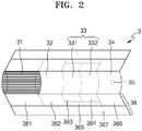
- FIGS. 2 and 3 are diagrams showing an example of an aerosol-generating article.
- the aerosol-generating article 3 includes a medium portion 31, a first hollow tube 32, a cooling portion 33, and a filter portion 34.
- the first portion 21 described above with reference to FIG. 1 includes the medium portion 31, and the second portion 22 includes the first hollow tube 32, the cooling portion 33, and the filter portion 34.
- the medium portion 31 may include an aerosol-generating material.
- the aerosol generating material may include at least one of glycerin, propylene glycol, ethylene glycol, dipropylene glycol, diethylene glycol, triethylene glycol, tetraethylene glycol, and oleyl alcohol, but it is not limited thereto.
- the medium portion 31 may include other additives, such as flavors, a wetting agent, and/or organic acid.
- the medium portion 31 may include a flavored liquid, such as menthol or a moisturizer, which is injected to the medium portion 31.
- the medium portion 31 may be manufactured in various forms.
- the medium portion 31 may be formed using sheets or strands.
- the medium portion 31 may be formed using tiny bits cut from a tobacco sheet.
- the medium portion 31 may be surrounded by a heat conductive material.
- the heat-conducting material may be, but is not limited to, a metal foil such as aluminum foil.
- the heat conductive material surrounding the medium portion 31 may uniformly distribute heat transmitted to the medium portion 31, and thus, the heat conductivity of the medium portion may be increased and taste of the tobacco may be improved.
- the heat conductive material surrounding the medium portion 31 may function as a susceptor heated by the induction heater.
- the medium portion 31 may further include an additional susceptor, in addition to the heat conductive material surrounding the medium portion 31.
- the first hollow tube 32 may be a cellulose acetate filter.
- the first hollow tube 32 may be a tube-shaped structure including the first hollow 371 therein.
- the first hollow tube 32 includes a first hollow 371 having a diameter D1, and the first hollow 371 may serve as a channel through which aerosol passes.
- a length of the first hollow tube 32 may be an appropriate length within a range of 4 mm to 30 mm, but is not limited thereto.
- the length of the first hollow tube 32 may be 10 mm, but is not limited thereto.
- the diameter D1 of the first hollow 371 may be an appropriate diameter within the range of 2 mm to 4.5 mm, but is not limited thereto.
- the diameter (D1) of the first hollow tube 32 may be 3.4 mm, but is not limited thereto.
- the cooling portion 33 cools the aerosol generated by a heater 13 heating the medium portion 31.
- the cooling portion 33 includes a cooling element 331 and a second hollow tube 332.
- a length or diameter of the cooling portion 33 may be variously determined according to a shape of the aerosol-generating article 300.
- the length of the cooling portion 33 may be a suitable length within a range of 7 mm to 20 mm.
- the length of the cooling portion 33 may be about 14 mm, but is not limited thereto.
- the cooling element 331 may cool the aerosol by a phase transition action.
- a material forming the cooling element 331 may perform the phase transition action, such as melting or glass transition, which requires absorption of thermal energy.
- a temperature of the aerosol passing through the cooling element 331 is lowered.
- the length of the cooling element 331 may be a suitable length within the range of 4 mm to 10 mm. Preferably, the length of the cooling element 331 may be about 7 mm, but is not limited thereto.
- the cooling element 331 may be made of a polymer material or a biodegradable polymer material alone.
- the polymer material includes, gelatin, polyethylene (PE), polypropylene (PP), polyurethane (PU), fluorinated ethylene propylene (FEP), and combinations thereof, but are not limited thereto.
- the biodegradable polymer material includes polylactic acid (PLA), polyhydroxybutyrate (PHB), cellulose acetate, poly-epsilon-caprolactone (PCL), polyglycolic acid (PGA), polyhydroxyalkanoate (PHAs) and starch-based thermoplastic resins, but are not limited thereto.
- the cooling element 331 may be made of pure polylactic acid alone.
- the cooling element 331 may be a three-dimensional structure shape produced by using one or more fiber strands (hereinafter referred to as 'fiber strands') made of pure polylactic acid.
- the thickness, length, number, and shape of the fiber strands constituting the cooling element 331 may vary.
- a specific material may be prevented from being generated in a process of passing the aerosol through the cooling element 331.
- the second hollow tube 332 may be a cellulose acetate filter.
- the second hollow tube 332 may be a tube-shaped structure including a second hollow 372 therein.
- the second hollow tube 332 may include the second hollow 372 having a diameter D2, and the second hollow 372 may serve as a channel through which the aerosol passes.
- the length of the second hollow tube 332 may be an appropriate length within the range of 4 mm to 10 mm, but is not limited thereto. Preferably, the length of the second hollow tube 332 may be about 7 mm, but is not limited thereto. For example, the length of the second hollow tube 332 may be shorter than the length of the first hollow tube 331, but is not limited thereto. As another example, the length of the second hollow tube 332 may be shorter than or equal to the length of the cooling element 331, but is not limited thereto.
- the diameter (D2) of the second hollow 372 may be an appropriate diameter within the range of 3 mm to 5 mm, but is not limited thereto.
- a diameter D2 of the second hollow tube 332 may be 4 mm, but is not limited thereto.
- the diameter D2 of the second hollow tube 332 may be the same or larger than the diameter D1 of the first hollow tube 331, but is not limited thereto. That is, a ratio of the diameter D2 of the second hollow tube 332 to the diameter D1 of the first hollow tube 331 may be equal or greater than 1.0, but is not limited thereto.
- the filter portion 34 is disposed at a rear end portion that contacts the user's mouth during smoking.
- a length of the filter portion 34 may be a suitable value in the range of 4 mm to 20 mm.
- the length of the filter portion 34 may be about 12 mm, but is not limited thereto.
- a flavoring liquid may be sprayed onto the filter unit 34 such that the filter portion 34 generates a flavor.
- a separate fiber coated with the fragrance liquid may be inserted into the filter portion 34.
- the aerosol generated in the medium portion 31 is cooled as the aerosol passes through the cooling portion 33, and the cooled aerosol is delivered to the user through the filter portion 34. Accordingly, when a flavoring element is added to the filter portion 34, there may be an effect of enhancing a persistence of flavor delivered to a user.
- the filter portion 34 may include at least one capsule 35.
- the capsule 35 may have a structure in which the content liquid containing a flavoring is wrapped with a film.
- the capsule 35 may have a spherical or cylindrical shape.
- the aerosol-generating article 3 may be packaged by at least one wrapper 36.
- the wrapper 36 may have at least one hole through which external air may be introduced or internal air may be discharged.
- the aerosol-generating article 3 may be packaged by one wrapper 36.
- the aerosol-generating article 3 may be double-packaged by at least two wrappers 36.
- the medium portion 31 may be wrapped by a first wrapper 361, the first hollow tube 32 may be wrapped by a second wrapper 362, the cooling element 331 may be wrapped by a third wrapper 363, the second hollow tube 332 may be wrapped by a fourth wrapper 364, and the filter portion 34 may be wrapped by the sixth wrapper 366.
- the cooling element 331 and the second hollow tube 332 wrapped by individual wrappers may be rewrapped by a fifth wrapper 365.
- the cooling element 331 and the second hollow tube 332 wrapped by the individual wrappers are not necessarily rewrapped by the fifth wrapper 365, and may not be rewrapped by the fifth wrapper 365.
- the medium portion 31, the first hollow tube 32, the cooling element 331, the second hollow tube 332, and the filter portion 34 may be combined, and an entire aerosol-generating article 3 may be rewrapped by a seventh wrapper 367.
- the medium portion 31 may be wrapped by the first wrapper 361, the first hollow tube 32 may be wrapped by the second wrapper 362, the cooling element 331 may be wrapped by the third wrapper 363, and the filter portion 34 may be wrapped by the sixth wrapper 366.
- the cooling element 331 wrapped by the individual wrapper and the second hollow tube 332 not wrapped by the individual wrapper may be wrapped by the fifth wrapper 365.
- the cooling element 331 and the second hollow tube 332 are not necessarily wrapped by the fifth wrapper 365 and may not be wrapped by the fifth wrapper 365.
- the medium portion 31, the first hollow tube 32, the cooling element 331, the second hollow tube 332, and the filter portion 34 may be combined, and the entire aerosol-generating article 3 may be rewrapped by the seventh wrapper 367.
- the cooling portion 33 of the aerosol-generating article 3 includes the cooling element 331 and the second hollow tube 332. That is, the total length of the cooling portion 33 is equal to the sum of the length of the cooling element 331 and the length of the second hollow tube 332.
- the manufacturing cost of the cooling element 331 is higher than the manufacturing cost of the second hollow tube 332
- a short cooling element 331 may be used.
- the cooling portion 33 may not be able to cool aerosol properly, so a cooling element 331 should have an appropriate length.
- the particle size increases.
- the diameter D2 of the second hollow 372 decreases, the probability that the aerosol having an increased particle size collides with the second hollow tube 332 increases. If the aerosol collides with the second hollow tube 332, some ingredients are absorbed by the second hollow tube 332, thus the aerosol generated in the medium 31 may not be sufficiently delivered to the user. For this reason, the second hollow 372 of the second hollow tube 332 should have a suitable diameter.
- Table 1 is a table comparing the ingredients and temperatures of the aerosol discharged from the aerosol-generating article 3 according to an example experiment.
- the total length of the cooling portion 33 used in this experiment is 14 mm, and the inner diameter D1 of the first hollow tube 32 is 3.4 mm.
- Experiments were performed on the case where the cooling portion 33 was composed only of the cooling element 331 and the case where the cooling portion 33 was composed of the cooling element 331 having a length of 7 mm and the second hollow tube 332 having a length of 7 mm and an inner diameter D2 of 4 mm.
- the desired cooling effect may be obtained even if the entire length 14 mm of the cooling portion 33 is composed of the cooling element 331 having a length of 7 mm and the second hollow tube 332 having a length of 7 mm.
- the inner diameter D2 of the second hollow tube 332 is greater than the inner diameter D1 of the first hollow tube 32, it may be seen that the ingredients of the aerosol may be sufficiently delivered to a user.
- Table 2 is a table comparing the ingredients of the aerosol discharged from the aerosol-generating article 3 according to an example experiment.
- the total length of the cooling portion 33 used in this experiment is 14 mm, and the inner diameter D1 of the first hollow tube 32 is 3.4 mm.
- Experiments were performed on the case where the entire cooling portion 33 was composed of the cooling element 331 and the case where the cooling portion 33 was composed of the cooling element 331 having a length of 7 mm and the second hollow tube 332 having a length of 7 mm and an inner diameter (D2) of 3.4 mm.
- the cooling portion 33 may be configured to include the cooling element 331 and the second hollow tube 332, thereby reducing manufacturing cost while maintaining the aerosol ingredient delivery function and cooling function of the aerosol-generating article 3.
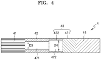
- FIG. 4 is a diagram showing another example of an aerosol-generating article.
- the aerosol-generating article 4 includes a medium portion 41, a first hollow tube 42, a cooling portion 43, and a filter portion 44.
- the aerosol-generating article 4 shown in FIG. 4 has the reverse order in which the cooling elements 431 and the second hollow tube 432 are arranged.
- the other configuration is the same as the aerosol-generating article 3 shown in FIGS. 2 and 3 .
- Table 3 is a table comparing the ingredients and temperatures of the aerosol discharged from the aerosol-generating article 4 according to an example experiment.
- the total length of the cooling portion 43 used in this experiment is 14 mm, and an inner diameter D3 of the first hollow tube 42 is 3.4 mm.
- Experiments were conducted on the case where the entire cooling portion 33 is composed of the cooling element, the case where the cooling portion 33 is composed of the cooling element 331 having a length of 7 mm and the second hollow tube 332 having a length of 7 mm and an inner diameter D2 of 4 mm according to the arrangement shown in FIG.
- an experimental result of a case (hereinafter, referred to as a first case) where the cooling element 331 is disposed on the upstream side and the second hollow tube 332 is disposed on the downstream side as shown in FIG. 3 is compared with an experimental result of a case (hereinafter, referred to as a second case) where the cooling element 431 is disposed on the downstream side and the second hollow tube 432 is disposed on the upstream side as shown in FIG. 4 .
- the amount of the discharged nicotine is 0.98 mg in the first case and 0.80 mg in the second case was 0.80 mg. That is, and the amount of nicotine delivered to a user in the second case is reduced by about 18% when compared to the first case.
- the maximum temperature and the average temperature of the aerosol discharged in the second case are 85.0 °C and 65.9 °C, respectively, which are higher than the maximum temperature 81.4 °C and the average temperature 65.0 °C of the aerosol discharged in the first case.
- the case where the cooling element 331 is disposed on the upstream side and the second hollow tube 332 is disposed on the downstream side as shown in FIG. 3 may provide a better smoking quality to the user.
Landscapes
- Chemical & Material Sciences (AREA)
- Engineering & Computer Science (AREA)
- Materials Engineering (AREA)
- Cigarettes, Filters, And Manufacturing Of Filters (AREA)
Abstract
Description
- The present invention relates to an aerosol-generating article, and more particularly, to an aerosol-generating article including a cooling portion including a cooling element and a hollow tube.
- Recently, the demand for alternative methods to overcome the shortcomings of general aerosol-generating articles has increased. For example, there is growing demand for a method of generating aerosol by heating an aerosol-generating material in aerosol-generating articles, rather than by combusting aerosol-generating articles. Accordingly, studies on a heating-type aerosol-generating article and a heating-type aerosol-generating device have been actively conducted.
- The aerosol-generating article may include a cooling element for cooling aerosol to below a certain temperature. The cooling element has the advantage of allowing a user to safely inhale the aerosol, but also has the disadvantage of increasing a cost of the aerosol-generating article due to the high manufacturing cost. Accordingly, research has been conducted to reduce the cost while maintaining a cooling function of the aerosol-generating article.
- The present invention is to provide an aerosol-generating article capable of reducing a cost while maintaining a cooling function. The technical problem to be solved is not limited to the technical problem as described above, and other technical problems may exist.
- An aerosol-generating article according to one embodiment includes a medium portion; a first hollow tube disposed to face a downstream end of the medium portion and including a first hollow; a cooling portion disposed next to a downstream side of the first hollow tube, including a second hollow tube including a second hollow having a diameter equal to or greater than a diameter of the first hollow and a cooling element; a filter portion disposed to face the downstream end of the cooling portion; and a wrapper wrapping at least a portion of the medium portion, the first hollow tube, the cooling portion, and the filter portion.
- According to the present invention, a manufacturing cost may be reduced while maintaining aerosol ingredient delivery function and a cooling function of the aerosol-generating article. Effects of the present invention are not limited by the contents exemplified above, and more various effects are included in the present specification.
-
-
FIG. 1 is a diagram illustrating that an aerosol-generating article is inserted into an aerosol-generating device. -
FIGS. 2 to 4 are diagrams illustrating examples of an aerosol-generating article. - An aerosol-generating article according to one embodiment includes a medium portion; a first hollow tube disposed to face a downstream end of the medium portion and including a first hollow; a cooling portion disposed next to a downstream side of the first hollow tube, and including a cooling element and a second hollow tube including a second hollow having a diameter equal to or greater than a diameter of the first hollow; a filter portion disposed to face the downstream end of the cooling portion; and a wrapper wrapping at least a portion of the medium portion, the first hollow tube, the cooling portion, and the filter portion.
- In the aerosol-generating article described above, a length of the second hollow tube is shorter than a length of the first hollow tube.
- In the aerosol-generating article described above, a length of the second hollow tube and a length of the cooling element are included within a range of 4 mm to 10 mm, respectively.
- In the aerosol-generating article described above, each of the cooling element and the second hollow tube is wrapped by a wrapper, and the wrapped cooling element and the wrapped second hollow tube are rewrapped by a single wrapper.
- In the aerosol-generating article described above, the cooling element is wrapped by a wrapper, and the wrapped cooling element and the second hollow tube are wrapped by a single wrapper.
- In the aerosol-generating article described above, the first hollow tube and the second hollow tube include cellulose acetate.
- In the aerosol-generating article described above, the cooling element includes a polymer fiber.
- In the aerosol-generating article described above, the cooling element and the second hollow tube are sequentially arranged downstream.
- With respect to the terms used to describe the various embodiments, general terms which are currently and widely used are selected in consideration of functions of structural elements in the various embodiments of the present disclosure. However, meanings of the terms can be changed according to intention, a judicial precedence, the appearance of new technology, and the like. In addition, in certain cases, some terms are arbitrarily selected by the applicant, and in this case, their meanings will be described in detail in the description of an invention. Therefore, the terms used in the present invention should be defined based on meanings of the terms and contents of the present invention, not simply names of the terms.
- In addition, unless explicitly described to the contrary, the word "comprise" and variations such as "comprises" or "comprising" will be understood to imply the inclusion of stated elements but not the exclusion of any other elements. In addition, the terms "-er", "-or", and "module" described in the specification mean units for processing at least one function and/or operation and can be implemented by hardware components or software components and combinations thereof.
- In the following embodiments, with respect to the terms "upstream" and "downstream", when a user inhales air using a smoking article, a portion in which air enters into an aerosol-generating article from the outside is referred to as "upstream", and a portion in which air exits from inside the aerosol-generating article to the outside is referred to as "downstream". The terms "upstream" and "downstream" are terms used to indicate a relative position or direction between the segments that constitute the aerosol-generating article.
- Hereinafter, the present disclosure will now be described more fully with reference to the accompanying drawings, in which exemplary embodiments of the present disclosure are shown such that one of ordinary skill in the art may easily work the present disclosure. The disclosure may, however, be embodied in many different forms and should not be construed as being limited to the embodiments set forth herein.
- Hereinafter, embodiments of the present invention will be described in detail with reference to the drawings.
-
FIG. 1 is a diagram illustrating an example in which an aerosol-generating article is inserted into an aerosol-generating device. - Referring to
FIG. 1 , the aerosol-generating device 1 may include abattery 11, acontroller 12, and aheater 13. Also, the aerosol-generatingarticle 2 may be inserted into an inner space of the aerosol-generating device 1. -
FIG. 1 shows the aerosol-generating device 1 with some elements related to the present embodiment. Therefore, it will be understood by one of ordinary skill in the art that other general-purpose components may be further included in the aerosol-generating device 1, in addition to the components illustrated inFIG. 1 . -
FIG. 1 illustrates that thebattery 11, thecontroller 12, and theheater 13 are arranged in series, but the arrangement of these are not limited thereto. In other words, according to the design of the aerosol-generating device 1, the arrangement of thebattery 11, thecontroller 12, and theheater 13 may be modified. - When the aerosol-generating
article 2 is inserted into the aerosol-generating device 1, the aerosol-generating device 1 heats theheater 13. The temperature of an aerosol-generating material in the aerosol-generatingarticle 2 is raised by the heatedheater 13, and thus aerosol is generated. - As necessary, even when the aerosol-generating
article 2 is not inserted into the aerosol-generating device 1, the aerosol-generating device 1 may heat theheater 13. - The
battery 11 may supply power to be used for the aerosol-generating device 1 to operate. For example, thebattery 11 may supply power for heating theheater 13 and supply power for operating thecontrol unit 12. Also, thebattery 11 may supply power for operations of a display, a sensor, a motor, etc. mounted in the aerosol-generating device 1. - The
controller 12 may control overall operations of the aerosol-generating device 1. In detail, thecontroller 12 controls not only operations of thebattery 11 and the heater, but also operations of other components included in the aerosol-generating device 1. Also, thecontroller 12 may check a state of each of the components of the aerosol-generating device 1 to determine whether or not the aerosol-generating device 1 is able to operate. - The
controller 12 may include at least one processor. A processor can be implemented as an array of a plurality of logic gates or can be implemented as a combination of a general-purpose microprocessor and a memory in which a program executable in the microprocessor is stored. It will be understood by one of ordinary skill in the art that the processor can be implemented in other forms of hardware. - The
heater 13 is heated by power supplied from thebattery 11. For example, when the aerosol-generatingarticle 2 is inserted into the aerosol-generating device 1, theheater 13 may be located inside the aerosol-generatingarticle 2. Thus, the heatedheater 13 may increase a temperature of an aerosol-generating material in the aerosol-generatingarticle 2. - The
heater 13 may include an electro-resistive heater. For example, theheater 13 may include an electrically conductive track, and theheater 13 may be heated when currents flow through the electrically conductive track. However, theheater 13 is not limited to the example described above and may include all heaters which may be heated to a desired temperature. Here, the desired temperature may be pre-set in the aerosol-generating device 1 or may be set as a temperature desired by a user. - As another example, the
heater 13 may include an induction heater. In detail, theheater 13 may include an electrically conductive coil for heating an aerosol-generating article in an induction heating method, and the aerosol-generating article may include a susceptor which may be heated by the induction heater. - The
heater 13 is inserted into the aerosol-generatingarticle 2 inFig. 1 , but it is not limited thereto. For example, theheater 13 may include a tube-type heating element, a plate-type heating element, a needle-type heating element, or a rod-type heating element, and may heat the inside or the outside of the aerosol-generatingarticle 2, according to the shape of the heating element. - Also, the aerosol generating device 1 may include a plurality of
heaters 13. Here, the plurality ofheaters 13 may be inserted into the aerosol-generatingarticle 2 or may be arranged outside the aerosol-generating article. Also, some of the plurality ofheaters 13 may be inserted into the aerosol-generatingarticle 2, and the others may be arranged outside the aerosol-generating article. In addition, the shape of theheater 13 is not limited to the shapes illustrated inFIG. 1 and may include various shapes. - The aerosol-generating device 1 may further include general-purpose components in addition to the
battery 11, thecontroller 12, and theheater 13. For example, the aerosol-generating device 1 may include a display capable of outputting visual information and/or a motor for outputting haptic information. Also, the aerosol-generating device 1 may include at least one sensor (a puff detecting sensor, a temperature detecting sensor, an aerosol-generating article insertion detecting sensor, etc.). - Also, the aerosol-generating device 1 may be formed as a structure where, even when the aerosol-generating
article 2 is inserted into the aerosol-generating device 1, external air may be introduced or internal air may be discharged. - Although not illustrated in
FIG. 1 , the aerosol-generating device 1 and an additional cradle may form together a system. For example, the cradle may be used to charge thebattery 11 of the aerosol-generating device 1. Alternatively, theheater 13 may be heated while the cradle and the aerosol-generating device 1 are coupled to each other. - The aerosol-generating
article 2 may be similar to a general combustive aerosol-generating article. For example, the aerosol-generatingarticle 2 may be divided into afirst portion 21 including an aerosol-generating material and asecond portion 22 including a filter or the like. Thesecond portion 22 of the aerosol-generatingarticle 2 may also include an aerosol-generating material. For example, an aerosol-generating material made in the form of granules or capsules may be inserted into thesecond portion 22. - The
first portion 21 may be completely inserted into the aerosol-generating device 1, and thesecond portion 22 may be exposed to the outside. In some embodiments, only a portion of thefirst portion 21 may be inserted into the aerosol-generating device 1. Otherwise, a portion of thefirst portion 21 and a portion of thesecond portion 22 may be inserted into the aerosol-generating device 1. The user may puff aerosol while holding thesecond portion 22 by the mouth of the user. In this case, the aerosol is generated by the external air passing through thefirst portion 21, and the generated aerosol passes through thesecond portion 22 and is delivered to the user's mouth. - For example, the external air may flow into at least one air passage formed in the aerosol-generating device 1. For example, opening and closing of the air passage and/or a size of the air passage may be adjusted by the user. Accordingly, the amount and quality of vapor may be adjusted by the user. As another example, the external air may flow into the aerosol-generating
article 2 through at least one hole formed in a surface of the aerosol-generatingarticle 2. - Hereinafter, an example of an aerosol-generating article will be described with reference to
FIGS. 2 and3 . -
FIGS. 2 and3 are diagrams showing an example of an aerosol-generating article. -
FIGS. 2 and3 , the aerosol-generatingarticle 3 includes amedium portion 31, a firsthollow tube 32, a coolingportion 33, and afilter portion 34. Thefirst portion 21 described above with reference toFIG. 1 includes themedium portion 31, and thesecond portion 22 includes the firsthollow tube 32, the coolingportion 33, and thefilter portion 34. - The
medium portion 31 may include an aerosol-generating material. For example, the aerosol generating material may include at least one of glycerin, propylene glycol, ethylene glycol, dipropylene glycol, diethylene glycol, triethylene glycol, tetraethylene glycol, and oleyl alcohol, but it is not limited thereto. Also, themedium portion 31 may include other additives, such as flavors, a wetting agent, and/or organic acid. Also, themedium portion 31 may include a flavored liquid, such as menthol or a moisturizer, which is injected to themedium portion 31. - The
medium portion 31 may be manufactured in various forms. For example, themedium portion 31 may be formed using sheets or strands. Also, themedium portion 31 may be formed using tiny bits cut from a tobacco sheet. - Also, the
medium portion 31 may be surrounded by a heat conductive material. For example, the heat-conducting material may be, but is not limited to, a metal foil such as aluminum foil. For example, the heat conductive material surrounding themedium portion 31 may uniformly distribute heat transmitted to themedium portion 31, and thus, the heat conductivity of the medium portion may be increased and taste of the tobacco may be improved. Also, the heat conductive material surrounding themedium portion 31 may function as a susceptor heated by the induction heater. Here, although not illustrated in the drawings, themedium portion 31 may further include an additional susceptor, in addition to the heat conductive material surrounding themedium portion 31. - The first
hollow tube 32 may be a cellulose acetate filter. The firsthollow tube 32 may be a tube-shaped structure including the first hollow 371 therein. In other words, the firsthollow tube 32 includes a first hollow 371 having a diameter D1, and the first hollow 371 may serve as a channel through which aerosol passes. A length of the firsthollow tube 32 may be an appropriate length within a range of 4 mm to 30 mm, but is not limited thereto. Preferably, the length of the firsthollow tube 32 may be 10 mm, but is not limited thereto. The diameter D1 of the first hollow 371 may be an appropriate diameter within the range of 2 mm to 4.5 mm, but is not limited thereto. Preferably, the diameter (D1) of the firsthollow tube 32 may be 3.4 mm, but is not limited thereto. - The cooling
portion 33 cools the aerosol generated by aheater 13 heating themedium portion 31. The coolingportion 33 includes acooling element 331 and a secondhollow tube 332. - A length or diameter of the cooling
portion 33 may be variously determined according to a shape of the aerosol-generating article 300. For example, the length of the coolingportion 33 may be a suitable length within a range of 7 mm to 20 mm. Preferably, the length of the coolingportion 33 may be about 14 mm, but is not limited thereto. - The
cooling element 331 may cool the aerosol by a phase transition action. For example, a material forming thecooling element 331 may perform the phase transition action, such as melting or glass transition, which requires absorption of thermal energy. As an endothermic reaction occurs at a temperature at which an aerosol enters thecooling element 331, a temperature of the aerosol passing through thecooling element 331 is lowered. - The length of the
cooling element 331 may be a suitable length within the range of 4 mm to 10 mm. Preferably, the length of thecooling element 331 may be about 7 mm, but is not limited thereto. - As an example, the
cooling element 331 may be made of a polymer material or a biodegradable polymer material alone. Here, examples of the polymer material includes, gelatin, polyethylene (PE), polypropylene (PP), polyurethane (PU), fluorinated ethylene propylene (FEP), and combinations thereof, but are not limited thereto. In addition, examples of the biodegradable polymer material includes polylactic acid (PLA), polyhydroxybutyrate (PHB), cellulose acetate, poly-epsilon-caprolactone (PCL), polyglycolic acid (PGA), polyhydroxyalkanoate (PHAs) and starch-based thermoplastic resins, but are not limited thereto. - In detail, the
cooling element 331 may be made of pure polylactic acid alone. For example, thecooling element 331 may be a three-dimensional structure shape produced by using one or more fiber strands (hereinafter referred to as 'fiber strands') made of pure polylactic acid. Here, the thickness, length, number, and shape of the fiber strands constituting thecooling element 331 may vary. As thecooling element 331 is made of pure polylactic acid, a specific material may be prevented from being generated in a process of passing the aerosol through thecooling element 331. - The second
hollow tube 332 may be a cellulose acetate filter. The secondhollow tube 332 may be a tube-shaped structure including a second hollow 372 therein. In other words, the secondhollow tube 332 may include the second hollow 372 having a diameter D2, and the second hollow 372 may serve as a channel through which the aerosol passes. - The length of the second
hollow tube 332 may be an appropriate length within the range of 4 mm to 10 mm, but is not limited thereto. Preferably, the length of the secondhollow tube 332 may be about 7 mm, but is not limited thereto. For example, the length of the secondhollow tube 332 may be shorter than the length of the firsthollow tube 331, but is not limited thereto. As another example, the length of the secondhollow tube 332 may be shorter than or equal to the length of thecooling element 331, but is not limited thereto. - The diameter (D2) of the second hollow 372 may be an appropriate diameter within the range of 3 mm to 5 mm, but is not limited thereto. Preferably, a diameter D2 of the second
hollow tube 332 may be 4 mm, but is not limited thereto. More preferably, the diameter D2 of the secondhollow tube 332 may be the same or larger than the diameter D1 of the firsthollow tube 331, but is not limited thereto. That is, a ratio of the diameter D2 of the secondhollow tube 332 to the diameter D1 of the firsthollow tube 331 may be equal or greater than 1.0, but is not limited thereto. - The
filter portion 34 is disposed at a rear end portion that contacts the user's mouth during smoking. A length of thefilter portion 34 may be a suitable value in the range of 4 mm to 20 mm. For example, the length of thefilter portion 34 may be about 12 mm, but is not limited thereto. - In the process of manufacturing the
filter portion 34, a flavoring liquid may be sprayed onto thefilter unit 34 such that thefilter portion 34 generates a flavor. Alternatively, a separate fiber coated with the fragrance liquid may be inserted into thefilter portion 34. The aerosol generated in themedium portion 31 is cooled as the aerosol passes through the coolingportion 33, and the cooled aerosol is delivered to the user through thefilter portion 34. Accordingly, when a flavoring element is added to thefilter portion 34, there may be an effect of enhancing a persistence of flavor delivered to a user. - Also, the
filter portion 34 may include at least onecapsule 35. Here, thecapsule 35 may have a structure in which the content liquid containing a flavoring is wrapped with a film. For example, thecapsule 35 may have a spherical or cylindrical shape. - The aerosol-generating
article 3 may be packaged by at least onewrapper 36. Thewrapper 36 may have at least one hole through which external air may be introduced or internal air may be discharged. For example, the aerosol-generatingarticle 3 may be packaged by onewrapper 36. As another example, the aerosol-generatingarticle 3 may be double-packaged by at least twowrappers 36. - For example, the
medium portion 31 may be wrapped by afirst wrapper 361, the firsthollow tube 32 may be wrapped by asecond wrapper 362, thecooling element 331 may be wrapped by athird wrapper 363, the secondhollow tube 332 may be wrapped by afourth wrapper 364, and thefilter portion 34 may be wrapped by thesixth wrapper 366. Thecooling element 331 and the secondhollow tube 332 wrapped by individual wrappers may be rewrapped by afifth wrapper 365. Thecooling element 331 and the secondhollow tube 332 wrapped by the individual wrappers are not necessarily rewrapped by thefifth wrapper 365, and may not be rewrapped by thefifth wrapper 365. In addition, themedium portion 31, the firsthollow tube 32, thecooling element 331, the secondhollow tube 332, and thefilter portion 34 may be combined, and an entire aerosol-generatingarticle 3 may be rewrapped by aseventh wrapper 367. - As another example, the
medium portion 31 may be wrapped by thefirst wrapper 361, the firsthollow tube 32 may be wrapped by thesecond wrapper 362, thecooling element 331 may be wrapped by thethird wrapper 363, and thefilter portion 34 may be wrapped by thesixth wrapper 366. Thecooling element 331 wrapped by the individual wrapper and the secondhollow tube 332 not wrapped by the individual wrapper may be wrapped by thefifth wrapper 365. Thecooling element 331 and the secondhollow tube 332 are not necessarily wrapped by thefifth wrapper 365 and may not be wrapped by thefifth wrapper 365. In addition, themedium portion 31, the firsthollow tube 32, thecooling element 331, the secondhollow tube 332, and thefilter portion 34 may be combined, and the entire aerosol-generatingarticle 3 may be rewrapped by theseventh wrapper 367. - As described above, the cooling
portion 33 of the aerosol-generatingarticle 3 includes thecooling element 331 and the secondhollow tube 332. That is, the total length of the coolingportion 33 is equal to the sum of the length of thecooling element 331 and the length of the secondhollow tube 332. In general, because the manufacturing cost of thecooling element 331 is higher than the manufacturing cost of the secondhollow tube 332, the longer the length of thecooling element 31 in the entire length of the coolingunit 33 is, the higher the manufacturing cost of the aerosol-generatingarticle 3 may be. In order to reduce the cost of the aerosol-generatingarticle 3, ashort cooling element 331 may be used. However, if thecooling element 331 is too short, the coolingportion 33 may not be able to cool aerosol properly, so acooling element 331 should have an appropriate length. - In addition, as the aerosol generated in the
medium portion 31 is cooled in the coolingportion 33, the particle size increases. As the diameter D2 of the second hollow 372 decreases, the probability that the aerosol having an increased particle size collides with the secondhollow tube 332 increases. If the aerosol collides with the secondhollow tube 332, some ingredients are absorbed by the secondhollow tube 332, thus the aerosol generated in the medium 31 may not be sufficiently delivered to the user. For this reason, the second hollow 372 of the secondhollow tube 332 should have a suitable diameter. - Table 1 is a table comparing the ingredients and temperatures of the aerosol discharged from the aerosol-generating
article 3 according to an example experiment. The total length of the coolingportion 33 used in this experiment is 14 mm, and the inner diameter D1 of the firsthollow tube 32 is 3.4 mm. Experiments were performed on the case where the coolingportion 33 was composed only of thecooling element 331 and the case where the coolingportion 33 was composed of thecooling element 331 having a length of 7 mm and the secondhollow tube 332 having a length of 7 mm and an inner diameter D2 of 4 mm.[Table 1] Ingredients of aerosol (mg) Temperature of aerosol (°C) TPM* Nicotine Glycerin Moisture Maximum temperature Average temperature Cooling element of 14mm length 45.08 0.96 3.18 30.72 82.1 65.3 Cooling element of 7 mm length + Second hollow tube of 7 mm length and 4mm inner diameter 44.89 0.98 3.36 30.16 81.4 65.0 *TPM: total particulate matter According to Table 1, when comparing the case where the length of the cooling element 331 is 14 mm and the case where thecooling element 331 is 7 mm, the ingredients and temperatures of the discharged aerosol in both cases have similar values. That is, it may be seen that the desired cooling effect may be obtained even if the entire length 14 mm of the coolingportion 33 is composed of thecooling element 331 having a length of 7 mm and the secondhollow tube 332 having a length of 7 mm. In addition, even if the inner diameter D2 of the secondhollow tube 332 is greater than the inner diameter D1 of the firsthollow tube 32, it may be seen that the ingredients of the aerosol may be sufficiently delivered to a user. - Table 2 is a table comparing the ingredients of the aerosol discharged from the aerosol-generating
article 3 according to an example experiment. The total length of the coolingportion 33 used in this experiment is 14 mm, and the inner diameter D1 of the firsthollow tube 32 is 3.4 mm. Experiments were performed on the case where theentire cooling portion 33 was composed of thecooling element 331 and the case where the coolingportion 33 was composed of thecooling element 331 having a length of 7 mm and the secondhollow tube 332 having a length of 7 mm and an inner diameter (D2) of 3.4 mm.[Table 2] Ingredients of aerosol (mg) TPM Nicotine Glycerin moisture Cooling element of 14 mm length 40.43 1.00 3.46 26.39 Cooling element of 7 mm length + Second hollow tube of 7 mm length and 3.4 mm inner diameter 40.48 0.94 3.05 26.80 - According to Table 2, when comparing the case where the
entire cooling portion 33 is composed of thecooling element 331 and the case where the coolingportion 33 is composed of acooling element 331 having a length of 7mm and a secondhollow tube 332 having a length of 7mm and an inner diameter D2 of 3.4mm, the ingredients of the discharged aerosol in both cases have similar values. In other words, even if the inner diameter D2 of the secondhollow tube 332 has the same size as the inner diameter D1 of the firsthollow tube 32, it may be seen that ingredients of the aerosol may be sufficiently delivered to a user. According to Table 1 and Table 2, it may be seen that the cooling effect may be maintained even if the coolingportion 33 further includes the secondhollow tube 332, in addition to thecooling element 331. Also, even if the inner diameter D2 of the secondhollow tube 332 is greater than or equal to the inner diameter D1 of the firsthollow tube 32, it may be seen that ingredients of the aerosol may be sufficiently delivered to a user. - Accordingly, the cooling
portion 33 may be configured to include thecooling element 331 and the secondhollow tube 332, thereby reducing manufacturing cost while maintaining the aerosol ingredient delivery function and cooling function of the aerosol-generatingarticle 3. -
FIG. 4 is a diagram showing another example of an aerosol-generating article. - Referring to
FIG. 4 , the aerosol-generatingarticle 4 includes amedium portion 41, a firsthollow tube 42, a coolingportion 43, and afilter portion 44. - Compared to the aerosol-generating
article 3 shown inFIGS. 2 and3 , the aerosol-generatingarticle 4 shown inFIG. 4 has the reverse order in which thecooling elements 431 and the secondhollow tube 432 are arranged. The other configuration is the same as the aerosol-generatingarticle 3 shown inFIGS. 2 and3 . - Table 3 is a table comparing the ingredients and temperatures of the aerosol discharged from the aerosol-generating
article 4 according to an example experiment. The total length of the coolingportion 43 used in this experiment is 14 mm, and an inner diameter D3 of the firsthollow tube 42 is 3.4 mm. Experiments were conducted on the case where theentire cooling portion 33 is composed of the cooling element, the case where the coolingportion 33 is composed of thecooling element 331 having a length of 7 mm and the secondhollow tube 332 having a length of 7 mm and an inner diameter D2 of 4 mm according to the arrangement shown inFIG. 3 , and the case where the coolingportion 43 is composed of thecooling element 431 having a length of 7 mm and the secondhollow tube 432 having a length of 7 mm and an inner diameter D4 of 4 mm according to the arrangement shown inFIG. 4 .[Table 3] Ingredients of aerosol (mg) Temperature of aerosol (°C) TPM Nicotine Glycerin Moisture Maximum temperature Average temperatur e Cooling element of 14 mm length 45.08 0.96 3.18 30.72 82.1 65.3 Cooling element of 7 mm length + Second hollow tube of 7mm length and 4 mm inner diameter + Arrangement of cooling element and second hollow tube as shown in FIG.3 44.89 0.98 3.36 30.16 81.4 65.0 Cooling element of 7 mm length + Second hollow tube of 7mm length and 4mm inner diameter + Arrangement of cooling element and second hollow tube as shown in FIG.4 43.37 0.80 2.42 28.63 85.0 65.9 - Based on Table 3, an experimental result of a case (hereinafter, referred to as a first case) where the
cooling element 331 is disposed on the upstream side and the secondhollow tube 332 is disposed on the downstream side as shown inFIG. 3 is compared with an experimental result of a case (hereinafter, referred to as a second case) where thecooling element 431 is disposed on the downstream side and the secondhollow tube 432 is disposed on the upstream side as shown inFIG. 4 .The amount of the discharged nicotine is 0.98 mg in the first case and 0.80 mg in the second case was 0.80 mg. That is, and the amount of nicotine delivered to a user in the second case is reduced by about 18% when compared to the first case. In addition, the maximum temperature and the average temperature of the aerosol discharged in the second case are 85.0 °C and 65.9 °C, respectively, which are higher than the maximum temperature 81.4 °C and the average temperature 65.0 °C of the aerosol discharged in the first case. - Accordingly, it may be seen that when compared with the case where the
cooling element 431 is disposed on the downstream side and the secondhollow tube 432 is disposed on the upstream side as shown inFIG. 4 , the case where thecooling element 331 is disposed on the upstream side and the secondhollow tube 332 is disposed on the downstream side as shown inFIG. 3 may provide a better smoking quality to the user. - Those of ordinary skill in the art related to the present embodiments may understand that various changes in form and details can be made therein without departing from the scope of the characteristics described above. The disclosed methods should be considered in a descriptive sense only and not for purposes of limitation. The scope of the present invention is shown in the claims rather than the foregoing description, and all differences within the equivalent range should be construed as being included in the present invention.
Claims (8)
- An aerosol-generating article comprising:a medium portion;a first hollow tube disposed to face a downstream end of the medium portion and including a first hollow;a cooling portion disposed next to a downstream side of the first hollow tube, and including a cooling element and a second hollow tube including a second hollow having a diameter equal to or greater than a diameter of the first hollow;a filter portion disposed to face a downstream end of the cooling portion; anda wrapper wrapping at least a portion of the medium portion, the first hollow tube, the cooling portion, and the filter portion.
- The aerosol-generating article of claim 1, wherein a length of the second hollow tube is shorter than a length of the first hollow tube.
- The aerosol-generating article of claim 1, wherein a length of the second hollow tube and a length of the cooling element are within a range of 4 mm to 10 mm, respectively.
- The aerosol-generating article of claim 1, wherein
each of the cooling element and the second hollow tube is wrapped by a wrapper, and
the wrapped cooling element and the wrapped second hollow tube are rewrapped by a single wrapper. - The aerosol-generating article of claim 1 wherein
the cooling element is wrapped by a wrapper, and
the wrapped cooling element and the second hollow tube are wrapped by a single wrapper. - The aerosol-generating article of claim 1, wherein the first hollow tube and the second hollow tube include cellulose acetate.
- The aerosol-generating article of claim 1, wherein the cooling element includes a polymer fiber.
- The aerosol-generating article of claim 1, wherein the cooling element and the second hollow tube are sequentially arranged downstream.
Applications Claiming Priority (2)
| Application Number | Priority Date | Filing Date | Title |
|---|---|---|---|
| KR1020180153011A KR102363395B1 (en) | 2018-11-30 | 2018-11-30 | Article for generating aerosol |
| PCT/KR2019/015611 WO2020111607A1 (en) | 2018-11-30 | 2019-11-15 | Aerosol generation article |
Publications (3)
| Publication Number | Publication Date |
|---|---|
| EP3818885A1 true EP3818885A1 (en) | 2021-05-12 |
| EP3818885A4 EP3818885A4 (en) | 2022-01-12 |
| EP3818885B1 EP3818885B1 (en) | 2025-10-08 |
Family
ID=70854063
Family Applications (1)
| Application Number | Title | Priority Date | Filing Date |
|---|---|---|---|
| EP19890461.7A Active EP3818885B1 (en) | 2018-11-30 | 2019-11-15 | Aerosol generation article |
Country Status (6)
| Country | Link |
|---|---|
| US (1) | US12171258B2 (en) |
| EP (1) | EP3818885B1 (en) |
| JP (2) | JP2021513332A (en) |
| KR (1) | KR102363395B1 (en) |
| CN (1) | CN111669981B (en) |
| WO (1) | WO2020111607A1 (en) |
Families Citing this family (10)
| Publication number | Priority date | Publication date | Assignee | Title |
|---|---|---|---|---|
| WO2021170638A1 (en) * | 2020-02-28 | 2021-09-02 | Philip Morris Products S.A. | Aerosol-generating article with improved configuration |
| US20230090088A1 (en) * | 2020-02-28 | 2023-03-23 | Philip Morris Products S.A. | Aerosol-generating article including substrate with gel composition |
| KR102526179B1 (en) * | 2020-06-15 | 2023-04-26 | 주식회사 케이티앤지 | Aerosol-generating article with improved aerosol cooling function |
| KR102581003B1 (en) * | 2020-06-15 | 2023-09-21 | 주식회사 케이티앤지 | Aerosol-generating article with improved aerosol level |
| GB202009163D0 (en) * | 2020-06-16 | 2020-07-29 | Nicoventures Trading Ltd | Article for use in non-combustible aerosol provision system |
| KR102546289B1 (en) * | 2020-10-19 | 2023-06-21 | 주식회사 케이티앤지 | Smoking article |
| KR102533027B1 (en) | 2020-11-10 | 2023-05-16 | 주식회사 케이티앤지 | Aerosol generating articles |
| GB202100865D0 (en) * | 2021-01-22 | 2021-03-10 | Nicoventures Trading Ltd | An article for use in a non-combistible aerosol provision system |
| KR102849258B1 (en) * | 2021-12-31 | 2025-08-22 | 주식회사 케이티앤지 | Cooling filter and smoking article comprising same |
| KR102885592B1 (en) * | 2022-10-11 | 2025-11-12 | 주식회사 케이티앤지 | Aerosol-generating article comprising cooling segment |
Family Cites Families (20)
| Publication number | Priority date | Publication date | Assignee | Title |
|---|---|---|---|---|
| KR20030093631A (en) * | 2002-06-04 | 2003-12-11 | 이중재 | a cigarettea filter |
| CN101925403B (en) * | 2008-01-25 | 2013-12-11 | R.J.雷诺兹烟草公司 | Method of making a breakable capsule for use in tobacco products |
| US8863750B2 (en) * | 2008-12-24 | 2014-10-21 | Philip Morris Usa Inc. | Filter cigarillo |
| GB201112466D0 (en) * | 2011-07-20 | 2011-08-31 | British American Tobacco Co | Smoking article |
| AT511344B1 (en) | 2011-10-21 | 2012-11-15 | Helmut Dr Buchberger | INHALATORKOMPONENTE |
| EP2625975A1 (en) | 2012-02-13 | 2013-08-14 | Philip Morris Products S.A. | Aerosol-generating article having an aerosol-cooling element |
| GB201213786D0 (en) | 2012-08-01 | 2012-09-12 | Filtrona Filter Prod Dev Co | Tobacco smoke filter |
| KR102354033B1 (en) | 2013-08-13 | 2022-01-24 | 필립모리스 프로덕츠 에스.에이. | Smoking article with single radially-separated heat-conducting element |
| BR112016002652B1 (en) | 2013-09-02 | 2021-09-08 | Philip Morris Products S.A | SMOKING ARTICLE |
| WO2015082652A1 (en) * | 2013-12-05 | 2015-06-11 | Philip Morris Products S.A. | Non-tobacco nicotine-containing article |
| TWI657755B (en) * | 2013-12-30 | 2019-05-01 | Philip Morris Products S. A. | Smoke containing heat-insulating combustible heat source |
| JP6663357B2 (en) * | 2014-05-21 | 2020-03-11 | フィリップ・モーリス・プロダクツ・ソシエテ・アノニム | Electric heating type aerosol generation system with end heater |
| WO2016021021A1 (en) | 2014-08-07 | 2016-02-11 | 日本たばこ産業株式会社 | Cigarette with filter |
| CA2981252A1 (en) * | 2015-03-31 | 2016-10-06 | Philip Morris Products S.A. | Smoking article with combustible heat source gripping means |
| TW201703660A (en) * | 2015-06-23 | 2017-02-01 | 菲利浦莫里斯製品股份有限公司 | Aerosol-generating article and method of producing aerosol-generating article |
| CN113925200B (en) | 2016-03-09 | 2024-10-29 | 菲利普莫里斯生产公司 | Aerosol-generating article |
| MX2018014310A (en) * | 2016-05-31 | 2019-02-25 | Philip Morris Products Sa | Aerosol-generating system comprising a heated aerosol-generating article. |
| KR20180070436A (en) | 2016-12-16 | 2018-06-26 | 주식회사 케이티앤지 | Method and apparatus for generating generating aerosols |
| CN207012052U (en) * | 2017-02-15 | 2018-02-16 | 浙江绍兴苏泊尔生活电器有限公司 | garlic peeling device |
| US12295420B2 (en) | 2017-04-11 | 2025-05-13 | Kt&G Corporation | Aerosol generation system of preheating heater |
-
2018
- 2018-11-30 KR KR1020180153011A patent/KR102363395B1/en active Active
-
2019
- 2019-11-15 CN CN201980010963.0A patent/CN111669981B/en active Active
- 2019-11-15 JP JP2020542300A patent/JP2021513332A/en active Pending
- 2019-11-15 WO PCT/KR2019/015611 patent/WO2020111607A1/en not_active Ceased
- 2019-11-15 EP EP19890461.7A patent/EP3818885B1/en active Active
- 2019-11-15 US US16/966,563 patent/US12171258B2/en active Active
-
2022
- 2022-04-07 JP JP2022063868A patent/JP7306776B2/en active Active
Also Published As
| Publication number | Publication date |
|---|---|
| WO2020111607A1 (en) | 2020-06-04 |
| KR20200066007A (en) | 2020-06-09 |
| KR102363395B1 (en) | 2022-02-15 |
| US12171258B2 (en) | 2024-12-24 |
| US20200359677A1 (en) | 2020-11-19 |
| CN111669981A (en) | 2020-09-15 |
| EP3818885B1 (en) | 2025-10-08 |
| CN111669981B (en) | 2024-02-06 |
| JP2022088657A (en) | 2022-06-14 |
| JP2021513332A (en) | 2021-05-27 |
| JP7306776B2 (en) | 2023-07-11 |
Similar Documents
| Publication | Publication Date | Title |
|---|---|---|
| US12171258B2 (en) | Aerosol generation article | |
| US11877592B2 (en) | Aerosol-generating article | |
| US20240206543A1 (en) | Cigarette and aerosol generation device for cigarette | |
| US11882869B2 (en) | Cigarette with outer wrapper | |
| EP3847915B1 (en) | Cigarette and aerosol generation device for cigarette | |
| US12262739B2 (en) | Aerosol generating system | |
| US20200288778A1 (en) | Vaporizer and aerosol generating device comprising same | |
| US12507740B2 (en) | Aerosol generating apparatus including pressure sensor | |
| US12102119B2 (en) | Aerosol generating article and aerosol generating system | |
| KR102467482B1 (en) | Cigarette and aerosol generating apparatus thereof | |
| US20220295886A1 (en) | Vaporizer and aerosol generating device comprising the same | |
| EP3908129B1 (en) | Aerosol-generating article including first wrapper and second wrapper, and aerosol-generating system using the aerosol-generating article | |
| KR102480476B1 (en) | Aerosol generating article and system comprising capsule | |
| EP4133958A1 (en) | Aerosol-generating device and control method therefor |
Legal Events
| Date | Code | Title | Description |
|---|---|---|---|
| STAA | Information on the status of an ep patent application or granted ep patent |
Free format text: STATUS: THE INTERNATIONAL PUBLICATION HAS BEEN MADE |
|
| PUAI | Public reference made under article 153(3) epc to a published international application that has entered the european phase |
Free format text: ORIGINAL CODE: 0009012 |
|
| STAA | Information on the status of an ep patent application or granted ep patent |
Free format text: STATUS: REQUEST FOR EXAMINATION WAS MADE |
|
| 17P | Request for examination filed |
Effective date: 20200813 |
|
| AK | Designated contracting states |
Kind code of ref document: A1 Designated state(s): AL AT BE BG CH CY CZ DE DK EE ES FI FR GB GR HR HU IE IS IT LI LT LU LV MC MK MT NL NO PL PT RO RS SE SI SK SM TR |
|
| REG | Reference to a national code |
Ref country code: DE Free format text: PREVIOUS MAIN CLASS: A24F0047000000 Ref country code: DE Ref legal event code: R079 Ref document number: 602019076742 Country of ref document: DE Free format text: PREVIOUS MAIN CLASS: A24F0047000000 Ipc: A24D0001020000 |
|
| A4 | Supplementary search report drawn up and despatched |
Effective date: 20211210 |
|
| RIC1 | Information provided on ipc code assigned before grant |
Ipc: A24D 1/20 20200101ALI20211206BHEP Ipc: A24D 1/02 20060101AFI20211206BHEP |
|
| DAV | Request for validation of the european patent (deleted) | ||
| DAX | Request for extension of the european patent (deleted) | ||
| STAA | Information on the status of an ep patent application or granted ep patent |
Free format text: STATUS: EXAMINATION IS IN PROGRESS |
|
| 17Q | First examination report despatched |
Effective date: 20230124 |
|
| P01 | Opt-out of the competence of the unified patent court (upc) registered |
Effective date: 20230526 |
|
| GRAP | Despatch of communication of intention to grant a patent |
Free format text: ORIGINAL CODE: EPIDOSNIGR1 |
|
| STAA | Information on the status of an ep patent application or granted ep patent |
Free format text: STATUS: GRANT OF PATENT IS INTENDED |
|
| INTG | Intention to grant announced |
Effective date: 20250512 |
|
| GRAS | Grant fee paid |
Free format text: ORIGINAL CODE: EPIDOSNIGR3 |
|
| GRAA | (expected) grant |
Free format text: ORIGINAL CODE: 0009210 |
|
| STAA | Information on the status of an ep patent application or granted ep patent |
Free format text: STATUS: THE PATENT HAS BEEN GRANTED |
|
| AK | Designated contracting states |
Kind code of ref document: B1 Designated state(s): AL AT BE BG CH CY CZ DE DK EE ES FI FR GB GR HR HU IE IS IT LI LT LU LV MC MK MT NL NO PL PT RO RS SE SI SK SM TR |
|
| REG | Reference to a national code |
Ref country code: GB Ref legal event code: FG4D Ref country code: CH Ref legal event code: F10 Free format text: ST27 STATUS EVENT CODE: U-0-0-F10-F00 (AS PROVIDED BY THE NATIONAL OFFICE) Effective date: 20251008 |
|
| REG | Reference to a national code |
Ref country code: DE Ref legal event code: R096 Ref document number: 602019076742 Country of ref document: DE |
|
| REG | Reference to a national code |
Ref country code: IE Ref legal event code: FG4D |
|
| PGFP | Annual fee paid to national office [announced via postgrant information from national office to epo] |
Ref country code: DE Payment date: 20251105 Year of fee payment: 7 |
|
| PGFP | Annual fee paid to national office [announced via postgrant information from national office to epo] |
Ref country code: GB Payment date: 20251030 Year of fee payment: 7 |
|
| PGFP | Annual fee paid to national office [announced via postgrant information from national office to epo] |
Ref country code: FR Payment date: 20251030 Year of fee payment: 7 |
|
| REG | Reference to a national code |
Ref country code: NL Ref legal event code: MP Effective date: 20251008 |
|
| REG | Reference to a national code |
Ref country code: AT Ref legal event code: MK05 Ref document number: 1844090 Country of ref document: AT Kind code of ref document: T Effective date: 20251008 |
|
| PG25 | Lapsed in a contracting state [announced via postgrant information from national office to epo] |
Ref country code: NL Free format text: LAPSE BECAUSE OF FAILURE TO SUBMIT A TRANSLATION OF THE DESCRIPTION OR TO PAY THE FEE WITHIN THE PRESCRIBED TIME-LIMIT Effective date: 20251008 |
|
| PG25 | Lapsed in a contracting state [announced via postgrant information from national office to epo] |
Ref country code: ES Free format text: LAPSE BECAUSE OF FAILURE TO SUBMIT A TRANSLATION OF THE DESCRIPTION OR TO PAY THE FEE WITHIN THE PRESCRIBED TIME-LIMIT Effective date: 20251008 |
|
| REG | Reference to a national code |
Ref country code: LT Ref legal event code: MG9D |
|
| PG25 | Lapsed in a contracting state [announced via postgrant information from national office to epo] |
Ref country code: NO Free format text: LAPSE BECAUSE OF FAILURE TO SUBMIT A TRANSLATION OF THE DESCRIPTION OR TO PAY THE FEE WITHIN THE PRESCRIBED TIME-LIMIT Effective date: 20260108 |
|
| PG25 | Lapsed in a contracting state [announced via postgrant information from national office to epo] |
Ref country code: AT Free format text: LAPSE BECAUSE OF FAILURE TO SUBMIT A TRANSLATION OF THE DESCRIPTION OR TO PAY THE FEE WITHIN THE PRESCRIBED TIME-LIMIT Effective date: 20251008 Ref country code: HR Free format text: LAPSE BECAUSE OF FAILURE TO SUBMIT A TRANSLATION OF THE DESCRIPTION OR TO PAY THE FEE WITHIN THE PRESCRIBED TIME-LIMIT Effective date: 20251008 Ref country code: FI Free format text: LAPSE BECAUSE OF FAILURE TO SUBMIT A TRANSLATION OF THE DESCRIPTION OR TO PAY THE FEE WITHIN THE PRESCRIBED TIME-LIMIT Effective date: 20251008 |
|
| PGFP | Annual fee paid to national office [announced via postgrant information from national office to epo] |
Ref country code: IT Payment date: 20260109 Year of fee payment: 7 |
|
| PG25 | Lapsed in a contracting state [announced via postgrant information from national office to epo] |
Ref country code: RS Free format text: LAPSE BECAUSE OF FAILURE TO SUBMIT A TRANSLATION OF THE DESCRIPTION OR TO PAY THE FEE WITHIN THE PRESCRIBED TIME-LIMIT Effective date: 20260108 |
|
| PG25 | Lapsed in a contracting state [announced via postgrant information from national office to epo] |
Ref country code: IS Free format text: LAPSE BECAUSE OF FAILURE TO SUBMIT A TRANSLATION OF THE DESCRIPTION OR TO PAY THE FEE WITHIN THE PRESCRIBED TIME-LIMIT Effective date: 20260208 |
|
| PG25 | Lapsed in a contracting state [announced via postgrant information from national office to epo] |
Ref country code: PT Free format text: LAPSE BECAUSE OF FAILURE TO SUBMIT A TRANSLATION OF THE DESCRIPTION OR TO PAY THE FEE WITHIN THE PRESCRIBED TIME-LIMIT Effective date: 20260209 |
|
| PG25 | Lapsed in a contracting state [announced via postgrant information from national office to epo] |
Ref country code: PL Free format text: LAPSE BECAUSE OF FAILURE TO SUBMIT A TRANSLATION OF THE DESCRIPTION OR TO PAY THE FEE WITHIN THE PRESCRIBED TIME-LIMIT Effective date: 20251008 |
|
| PG25 | Lapsed in a contracting state [announced via postgrant information from national office to epo] |
Ref country code: LV Free format text: LAPSE BECAUSE OF FAILURE TO SUBMIT A TRANSLATION OF THE DESCRIPTION OR TO PAY THE FEE WITHIN THE PRESCRIBED TIME-LIMIT Effective date: 20251008 |
|
| PG25 | Lapsed in a contracting state [announced via postgrant information from national office to epo] |
Ref country code: BG Free format text: LAPSE BECAUSE OF FAILURE TO SUBMIT A TRANSLATION OF THE DESCRIPTION OR TO PAY THE FEE WITHIN THE PRESCRIBED TIME-LIMIT Effective date: 20251008 |