EP3817704B1 - Dispositif comprenant un objet avec une pointe chauffante et biocompatible - Google Patents
Dispositif comprenant un objet avec une pointe chauffante et biocompatible Download PDFInfo
- Publication number
- EP3817704B1 EP3817704B1 EP19759015.1A EP19759015A EP3817704B1 EP 3817704 B1 EP3817704 B1 EP 3817704B1 EP 19759015 A EP19759015 A EP 19759015A EP 3817704 B1 EP3817704 B1 EP 3817704B1
- Authority
- EP
- European Patent Office
- Prior art keywords
- magnetic field
- field generator
- heating
- tip
- temperature
- Prior art date
- Legal status (The legal status is an assumption and is not a legal conclusion. Google has not performed a legal analysis and makes no representation as to the accuracy of the status listed.)
- Active
Links
Images






Classifications
-
- A—HUMAN NECESSITIES
- A61—MEDICAL OR VETERINARY SCIENCE; HYGIENE
- A61B—DIAGNOSIS; SURGERY; IDENTIFICATION
- A61B17/00—Surgical instruments, devices or methods
- A61B17/32—Surgical cutting instruments
- A61B17/3209—Incision instruments
- A61B17/3211—Surgical scalpels, knives; Accessories therefor
-
- A—HUMAN NECESSITIES
- A61—MEDICAL OR VETERINARY SCIENCE; HYGIENE
- A61F—FILTERS IMPLANTABLE INTO BLOOD VESSELS; PROSTHESES; DEVICES PROVIDING PATENCY TO, OR PREVENTING COLLAPSING OF, TUBULAR STRUCTURES OF THE BODY, e.g. STENTS; ORTHOPAEDIC, NURSING OR CONTRACEPTIVE DEVICES; FOMENTATION; TREATMENT OR PROTECTION OF EYES OR EARS; BANDAGES, DRESSINGS OR ABSORBENT PADS; FIRST-AID KITS
- A61F7/00—Heating or cooling appliances for medical or therapeutic treatment of the human body
- A61F7/007—Heating or cooling appliances for medical or therapeutic treatment of the human body characterised by electric heating
-
- A—HUMAN NECESSITIES
- A61—MEDICAL OR VETERINARY SCIENCE; HYGIENE
- A61H—PHYSICAL THERAPY APPARATUS, e.g. DEVICES FOR LOCATING OR STIMULATING REFLEX POINTS IN THE BODY; ARTIFICIAL RESPIRATION; MASSAGE; BATHING DEVICES FOR SPECIAL THERAPEUTIC OR HYGIENIC PURPOSES OR SPECIFIC PARTS OF THE BODY
- A61H39/00—Devices for locating or stimulating specific reflex points of the body for physical therapy, e.g. acupuncture
- A61H39/06—Devices for heating or cooling such points within cell-life limits
-
- A—HUMAN NECESSITIES
- A61—MEDICAL OR VETERINARY SCIENCE; HYGIENE
- A61H—PHYSICAL THERAPY APPARATUS, e.g. DEVICES FOR LOCATING OR STIMULATING REFLEX POINTS IN THE BODY; ARTIFICIAL RESPIRATION; MASSAGE; BATHING DEVICES FOR SPECIAL THERAPEUTIC OR HYGIENIC PURPOSES OR SPECIFIC PARTS OF THE BODY
- A61H39/00—Devices for locating or stimulating specific reflex points of the body for physical therapy, e.g. acupuncture
- A61H39/08—Devices for applying needles to such points, i.e. for acupuncture ; Acupuncture needles or accessories therefor
-
- A—HUMAN NECESSITIES
- A61—MEDICAL OR VETERINARY SCIENCE; HYGIENE
- A61H—PHYSICAL THERAPY APPARATUS, e.g. DEVICES FOR LOCATING OR STIMULATING REFLEX POINTS IN THE BODY; ARTIFICIAL RESPIRATION; MASSAGE; BATHING DEVICES FOR SPECIAL THERAPEUTIC OR HYGIENIC PURPOSES OR SPECIFIC PARTS OF THE BODY
- A61H39/00—Devices for locating or stimulating specific reflex points of the body for physical therapy, e.g. acupuncture
- A61H39/08—Devices for applying needles to such points, i.e. for acupuncture ; Acupuncture needles or accessories therefor
- A61H39/086—Acupuncture needles
-
- H—ELECTRICITY
- H01—ELECTRIC ELEMENTS
- H01F—MAGNETS; INDUCTANCES; TRANSFORMERS; SELECTION OF MATERIALS FOR THEIR MAGNETIC PROPERTIES
- H01F1/00—Magnets or magnetic bodies characterised by the magnetic materials therefor; Selection of materials for their magnetic properties
- H01F1/01—Magnets or magnetic bodies characterised by the magnetic materials therefor; Selection of materials for their magnetic properties of inorganic materials
- H01F1/012—Magnets or magnetic bodies characterised by the magnetic materials therefor; Selection of materials for their magnetic properties of inorganic materials adapted for magnetic entropy change by magnetocaloric effect, e.g. used as magnetic refrigerating material
- H01F1/015—Metals or alloys
-
- A—HUMAN NECESSITIES
- A61—MEDICAL OR VETERINARY SCIENCE; HYGIENE
- A61B—DIAGNOSIS; SURGERY; IDENTIFICATION
- A61B17/00—Surgical instruments, devices or methods
- A61B2017/00017—Electrical control of surgical instruments
- A61B2017/00022—Sensing or detecting at the treatment site
- A61B2017/00084—Temperature
-
- A—HUMAN NECESSITIES
- A61—MEDICAL OR VETERINARY SCIENCE; HYGIENE
- A61B—DIAGNOSIS; SURGERY; IDENTIFICATION
- A61B17/00—Surgical instruments, devices or methods
- A61B2017/00017—Electrical control of surgical instruments
- A61B2017/00115—Electrical control of surgical instruments with audible or visual output
-
- A—HUMAN NECESSITIES
- A61—MEDICAL OR VETERINARY SCIENCE; HYGIENE
- A61F—FILTERS IMPLANTABLE INTO BLOOD VESSELS; PROSTHESES; DEVICES PROVIDING PATENCY TO, OR PREVENTING COLLAPSING OF, TUBULAR STRUCTURES OF THE BODY, e.g. STENTS; ORTHOPAEDIC, NURSING OR CONTRACEPTIVE DEVICES; FOMENTATION; TREATMENT OR PROTECTION OF EYES OR EARS; BANDAGES, DRESSINGS OR ABSORBENT PADS; FIRST-AID KITS
- A61F7/00—Heating or cooling appliances for medical or therapeutic treatment of the human body
- A61F2007/0086—Heating or cooling appliances for medical or therapeutic treatment of the human body with a thermostat
-
- A—HUMAN NECESSITIES
- A61—MEDICAL OR VETERINARY SCIENCE; HYGIENE
- A61F—FILTERS IMPLANTABLE INTO BLOOD VESSELS; PROSTHESES; DEVICES PROVIDING PATENCY TO, OR PREVENTING COLLAPSING OF, TUBULAR STRUCTURES OF THE BODY, e.g. STENTS; ORTHOPAEDIC, NURSING OR CONTRACEPTIVE DEVICES; FOMENTATION; TREATMENT OR PROTECTION OF EYES OR EARS; BANDAGES, DRESSINGS OR ABSORBENT PADS; FIRST-AID KITS
- A61F7/00—Heating or cooling appliances for medical or therapeutic treatment of the human body
- A61F2007/0093—Heating or cooling appliances for medical or therapeutic treatment of the human body programmed
-
- A—HUMAN NECESSITIES
- A61—MEDICAL OR VETERINARY SCIENCE; HYGIENE
- A61H—PHYSICAL THERAPY APPARATUS, e.g. DEVICES FOR LOCATING OR STIMULATING REFLEX POINTS IN THE BODY; ARTIFICIAL RESPIRATION; MASSAGE; BATHING DEVICES FOR SPECIAL THERAPEUTIC OR HYGIENIC PURPOSES OR SPECIFIC PARTS OF THE BODY
- A61H39/00—Devices for locating or stimulating specific reflex points of the body for physical therapy, e.g. acupuncture
- A61H2039/005—Devices for locating or stimulating specific reflex points of the body for physical therapy, e.g. acupuncture by means of electromagnetic waves, e.g. I.R., U.V. rays
-
- A—HUMAN NECESSITIES
- A61—MEDICAL OR VETERINARY SCIENCE; HYGIENE
- A61H—PHYSICAL THERAPY APPARATUS, e.g. DEVICES FOR LOCATING OR STIMULATING REFLEX POINTS IN THE BODY; ARTIFICIAL RESPIRATION; MASSAGE; BATHING DEVICES FOR SPECIAL THERAPEUTIC OR HYGIENIC PURPOSES OR SPECIFIC PARTS OF THE BODY
- A61H2201/00—Characteristics of apparatus not provided for in the preceding codes
- A61H2201/02—Characteristics of apparatus not provided for in the preceding codes heated or cooled
- A61H2201/0207—Characteristics of apparatus not provided for in the preceding codes heated or cooled heated
-
- A—HUMAN NECESSITIES
- A61—MEDICAL OR VETERINARY SCIENCE; HYGIENE
- A61H—PHYSICAL THERAPY APPARATUS, e.g. DEVICES FOR LOCATING OR STIMULATING REFLEX POINTS IN THE BODY; ARTIFICIAL RESPIRATION; MASSAGE; BATHING DEVICES FOR SPECIAL THERAPEUTIC OR HYGIENIC PURPOSES OR SPECIFIC PARTS OF THE BODY
- A61H2201/00—Characteristics of apparatus not provided for in the preceding codes
- A61H2201/02—Characteristics of apparatus not provided for in the preceding codes heated or cooled
- A61H2201/0221—Mechanism for heating or cooling
-
- A—HUMAN NECESSITIES
- A61—MEDICAL OR VETERINARY SCIENCE; HYGIENE
- A61H—PHYSICAL THERAPY APPARATUS, e.g. DEVICES FOR LOCATING OR STIMULATING REFLEX POINTS IN THE BODY; ARTIFICIAL RESPIRATION; MASSAGE; BATHING DEVICES FOR SPECIAL THERAPEUTIC OR HYGIENIC PURPOSES OR SPECIFIC PARTS OF THE BODY
- A61H2201/00—Characteristics of apparatus not provided for in the preceding codes
- A61H2201/10—Characteristics of apparatus not provided for in the preceding codes with further special therapeutic means, e.g. electrotherapy, magneto therapy or radiation therapy, chromo therapy, infrared or ultraviolet therapy
-
- A—HUMAN NECESSITIES
- A61—MEDICAL OR VETERINARY SCIENCE; HYGIENE
- A61H—PHYSICAL THERAPY APPARATUS, e.g. DEVICES FOR LOCATING OR STIMULATING REFLEX POINTS IN THE BODY; ARTIFICIAL RESPIRATION; MASSAGE; BATHING DEVICES FOR SPECIAL THERAPEUTIC OR HYGIENIC PURPOSES OR SPECIFIC PARTS OF THE BODY
- A61H2201/00—Characteristics of apparatus not provided for in the preceding codes
- A61H2201/50—Control means thereof
-
- A—HUMAN NECESSITIES
- A61—MEDICAL OR VETERINARY SCIENCE; HYGIENE
- A61H—PHYSICAL THERAPY APPARATUS, e.g. DEVICES FOR LOCATING OR STIMULATING REFLEX POINTS IN THE BODY; ARTIFICIAL RESPIRATION; MASSAGE; BATHING DEVICES FOR SPECIAL THERAPEUTIC OR HYGIENIC PURPOSES OR SPECIFIC PARTS OF THE BODY
- A61H2201/00—Characteristics of apparatus not provided for in the preceding codes
- A61H2201/50—Control means thereof
- A61H2201/5023—Interfaces to the user
- A61H2201/5043—Displays
-
- A—HUMAN NECESSITIES
- A61—MEDICAL OR VETERINARY SCIENCE; HYGIENE
- A61H—PHYSICAL THERAPY APPARATUS, e.g. DEVICES FOR LOCATING OR STIMULATING REFLEX POINTS IN THE BODY; ARTIFICIAL RESPIRATION; MASSAGE; BATHING DEVICES FOR SPECIAL THERAPEUTIC OR HYGIENIC PURPOSES OR SPECIFIC PARTS OF THE BODY
- A61H2201/00—Characteristics of apparatus not provided for in the preceding codes
- A61H2201/50—Control means thereof
- A61H2201/5058—Sensors or detectors
- A61H2201/5082—Temperature sensors
Definitions
- the present invention relates to a device comprising an object with a heating, sharp or pointed tip, biocompatible usable in traditional treatments such as acupuncture or moxibustion, or even in any physiopathological table indicating moxibustion as a therapeutic means in medicine, and in particular in traditional Chinese medicine.
- the present invention can in particular be used in the cosmetic treatment of fine lines, dark circles and superficial cellulite or in the treatment of varicose veins and/or in the treatment of syndromes linked to spondylalgia and pain linked to these different conditions, in particular chronic lower back pain or neck pain and their projected pain.
- Acupuncture or moxibustion are traditional therapeutic techniques linked to Chinese medical tradition.
- Acupuncture consists of stimulating specific areas of the skin (dermis, epidermis, hypodermis) called "acupuncture points" using more or less fine needles.
- Moxibustion consists of stimulating acupuncture points with heat.
- moxibustion cannot be used in a confined space (for example in an office or an orbital station) due to the release of smoke unless a smoke extraction hood or moxa is available that does not release fumes that could be toxic.
- a heated acupuncture needle comprising an external heat source and a heating means in the form of a thermal conductor integrated into the needle along the entire length thereof.
- the first disadvantage of this technique is that it requires a needle comprising several successive layers and is therefore difficult to manufacture.
- the second disadvantage is that the different layers made to form the heating means can, due to the repeated application of heat or electricity, deteriorate quickly with the risk of short circuit contraindicating use.
- this technique does not allow precise control of the temperature at the tip of the needle.
- the document CN 20276168 describes a moxibustion system where the temperature is controlled by induction.
- this document only concerns "external" moxibustion, i.e., on the surface of the skin. Therefore, there is no way to precisely control the temperature applied inside the body.
- the international patent application WO2016/032109 describes an acupuncture device comprising heated acupuncture needles with all the technical characteristics of the preamble of claim 1.
- the present invention relates to a device according to claim 1. Subsidiary aspects of the invention are provided in the dependent claims.
- the present invention consists of a device comprising an object which comprises a biocompatible, pointed, heated acupuncture needle, and which comprises at least one ferromagnetic material, a magnetic field generator adapted to direct the magnetic field of the ferromagnetic material in order to produce a temperature rise in the acupuncture needle of the object, and a device for controlling the temperature of the acupuncture needle of the object.
- Said magnetic field generator has the shape of a hollow cylindrical pebble, intended to be placed on the skin, which comprises an orifice crossed perpendicularly by said object.
- Said magnetic field generator has a diameter ranging from 20 mm to 80 mm, and a thickness ranging from 0.5 mm to 25 mm.
- the device according to the invention allows for precise and secure control of the temperature at the heating tip of the object by means of the temperature control device.
- the temperature of the tip of the object can be perfectly calibrated to a set temperature set by the practitioner.
- the device according to the invention is easy to manufacture and implement.
- said magnetic field generator consists of a shell made of insulating material.
- said magnetic field generator is made of a shell of conductive material, preferably a shell of conductive metal.
- said orifice of the magnetic field generator has a diameter ranging from 0.1 mm to 10 mm, preferably from 0.1 mm to 5 mm.
- the ferromagnetic material is present throughout the object.
- the object is at least partially covered with a layer of insulating material, preferably is completely covered with a layer of insulating material except for the heating tip.
- the object further comprises an insulating or heating disc intended to be placed on the skin which comprises an orifice crossed perpendicularly by the object.
- the magnetic field generator further comprises ferrite arranged to direct the magnetic field along the longitudinal axis of the object.
- the temperature control device of the device of the invention is connected to the magnetic field generator and comprises a) a device for displaying the temperature of the tip of the object - the acupuncture needle -, b) means for determining a set temperature, and c) a device for controlling the magnetic field generator so that the temperature of the tip of the object - the acupuncture needle - is equal to the set temperature.
- the ferromagnetic material is chosen from steels, preferably chosen from ferritic stainless steels, martensitic stainless steels, and mixtures of these steels, more preferably chosen from martensitic stainless steel 420, martensitic stainless steel 416, stainless steel ferritic 430 and mixtures of these steels, and in particular the ferromagnetic material is martensitic stainless steel 420.
- the tip of the object - the acupuncture needle - is covered at least in part with a biocompatible material, preferably the biocompatible material is chosen from silicone, polytetrafluoroethylene (Teflon), and a hydrophilic polymer, and more preferably is silicone.
- a biocompatible material is chosen from silicone, polytetrafluoroethylene (Teflon), and a hydrophilic polymer, and more preferably is silicone.
- the device 1 comprises an object 2 comprising a heating, sharp, biocompatible tip, such as a scalpel blade and which comprises at least one ferromagnetic material 9, not shown in the Fig. 1 .
- the device also comprises a magnetic field generator 3 adapted to direct the magnetic field of the ferromagnetic material in order to produce a temperature rise in the heating tip of the object 2 and a temperature control device 4 of the heating tip of the object 2.
- the temperature control device 4 acts on the magnetic field generator 3 by supplying a current. This current will produce a magnetic field. The magnetic field thus generated will orient the particles of the ferromagnetic material 9 (not shown in the Fig.
- the object 2 is covered at least in part with a layer of insulating material 10, preferably is completely covered with a layer of insulating material 10 with the exception of the heating tip.
- This insulating material can be chosen from all existing insulating materials, and in particular can be chosen from plastics. This insulating material makes it possible to thermally insulate the rest of the object 2, apart from the tip. Thus, only the tip of the object 2 is hot and not the entire object 2. The skin and organs that may be in contact with the rest of object 2 are not heated.
- the device 1 comprises an object 2 comprising a biocompatible, pointed, heating tip, such as an acupuncture needle and which comprises at least one ferromagnetic material 9, not shown in these figures.
- the device also comprises a magnetic field generator 3 adapted to direct the magnetic field of the ferromagnetic material in order to produce a temperature rise in the heating tip of the object 2 and a temperature control device 4 of the heating tip of the object 2.
- the magnetic field generator 3 is not fixed to the object 2.
- the temperature control device 4 acts on the magnetic field generator 3 by supplying a current. This current will produce a magnetic field.
- the magnetic field thus generated will orient the particles of the ferromagnetic material 9 (not shown here) contained in the object 2, preferably throughout the object 2, and thus produce an increase in the temperature of the entire interior of the object 2.
- the temperature of the tip of the object 2 can be controlled by means, for example, of a thermometer or a thermocouple (not shown here), the temperature control device 4 thus modifying the current supplied to the magnetic field generator 3.
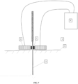
- Fig. 3 shows an embodiment according to the invention, in which the magnetic field generator 3 of the device 1 has the shape of a cylindrical roller, intended to be placed on the skin 5 which comprises an orifice crossed perpendicularly by the object 2.
- said roller is insulating, that is to say that it is generally made of a shell of insulating material, such as a shell of plastic, glass or aluminum.
- said roller is heating, that is to say that it is generally made of a shell of conductive material, such as a conductive metal.
- the conductive material constituting the shell of said roller is preferably the same as that of the heating tip of the object 2.
- said roller When said roller is heating, it can be heated thanks to the generated magnetic field which will orient the particles of the ferromagnetic material 9 (not shown here) contained in the shell of said roller.
- the use of said roller made of a shell of insulating material makes it possible not to heat the skin and to concentrate the heating only on the heating tip of the object 2, for example for localized treatments.
- the use of said roller made of a shell of conductive material makes it possible to heat the skin, for example for non-localized treatments.
- Fig. 4 shows a device for understanding the context of the invention, in which the object 2 and the magnetic field generator 3 are connected to the temperature control device 4 by means of a wireless connection.
- This wireless connection can be, for example, a Bluetooth connection or a Wi-Fi connection, which in particular makes it possible to add suction cup treatment to the device.
- Fig. 5 shows a device for understanding the context of the invention, in which the device 1 further comprises a disc 6, insulating or heating, intended to be placed on the skin 5 which comprises an orifice crossed perpendicularly by the object 2.
- the disc 6 is insulating, that is to say that it is generally made of an insulating material, such as a plastic material or glass.
- the disc 6 is heating, that is to say that it is generally made of a conductive material, such as a conductive metal.
- the conductive material constituting the disc is preferably the same as that of the heating tip of the object 2.
- the disc 6 When the disc 6 is heating, it can be heated in two ways: either independently of the heating tip of the object 2 for example by a heating system or by the object 2 by heat transfer by conduction.
- the additional use of the insulating disc 6 makes it possible not to heat the skin and to concentrate the heating only on the heating tip of the object 2, for example for localized treatments.
- the additional use of the heating disc 6 makes it possible to heat the skin, for example for non-localized treatments.
- FIG. 6 shows a device for understanding the context of the invention
- the Figure 7 shows an embodiment according to the invention, in which the magnetic field generator 3 of the device 1 further comprises ferrite 7 arranged so as to direct the magnetic field along the longitudinal axis of the object 2.
- the use of the ferrite 7 has the advantage of directing the magnetic field produced by the magnetic field generator 3 towards the tip of the heating object 2. This allows in particular to control, in a precise manner, the temperature reached by the tip of the heating object 2.
- Fig. 8 shows in horizontal section view the embodiment as described in the Fig 5 And 7 .
- the ferrite 7 has the shape of a cylinder and is arranged around the object 2.
- the magnetic field generator 3 also has the shape of a cylinder and is arranged around the ferrite 7.
- the support 8, for example made of plastic, serves to connect the magnetic field generator 3 to the ferrite 7, the assembly being connected to the object 2, this connection not being shown here.
- Fig. 9 shows a device for understanding the context of the invention, in which the ferromagnetic material 9 is located throughout the object 2.
- the object 2 is covered at least in part with a layer of insulating material 10, preferably is completely covered with a layer of insulating material 10 with the exception of the heating tip.
- This insulating material can be chosen from all existing insulating materials, and in particular can be chosen from plastics. This insulating material makes it possible to thermally insulate the rest of the object 2, apart from the tip. Thus, only the tip of the object 2 is hot and not the entire object 2. The skin and the organs that may be in contact with the rest of the object 2 are not heated.
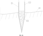
- Fig. 10 shows an enlargement of an embodiment according to the invention, in which the device 1 comprises an object 2 comprising a biocompatible, pointed, heating tip, such as an acupuncture needle and which comprises at least one ferromagnetic material 9.
- the pointed, heating tip is surrounded by a biocompatible material 11 such as silicone, polytetrafluoroethylene (Teflon), a hydrophilic polymer, and preferably is silicone.
- Fig. 11 shows an enlargement of an embodiment according to the invention, in which the device 1 comprises an object 2 comprising a heating, pointed, biocompatible tip, such as an acupuncture needle and which comprises at least one ferromagnetic material 9.
- the ferromagnetic material 9 is present in the entirety of the object 2.
- the object 2 is covered at least in part with a layer of insulating material 10, preferably is completely covered with a layer of insulating material 10 with the exception of the heating tip.
- This insulating material can be chosen from all existing insulating materials, and in particular can be chosen from plastics.
- the object 2 is completely covered with a biocompatible material 11 such as silicone, polytetrafluoroethylene (Teflon), a hydrophilic polymer, and preferably the biocompatible material is silicone.
- Fig. 12 shows a temperature control device 4 of the device 1 of an embodiment according to the invention.
- the temperature control device comprises a device for displaying the temperature of the tip of the object 12 and the set temperature 15, means 13 for determining a set temperature, such as for example a + button and a - button, and a switch 14.
- the user can set a set temperature 14 by means of the means 13.
- the temperature of the tip of the object represented by the display device 12, will change until it reaches the set temperature 15.
- the temperature of the tip of the object 2 can be measured for example by means of a thermometer or a thermocouple, not shown here, connected to the temperature control device 4.
- the user can permanently maintain control over the rise in the temperature of the tip of the object 2 by means of the switch 14 which makes it possible to completely interrupt the heating of the tip of the object. object 2.
- This switch 14 can also be used to stop the device 1 according to the invention at the end of use.
- the heating tip of the object 2 is sharp, that is to say that it has an elongated shape which has a side worked so as to cut material, in particular skin.
- the heating tip is a scalpel or bistoury blade.
- the object 2 is a scalpel or bistoury.
- the heating tip of the object 2 is sharp, in a device making it possible to understand the context of the invention, the heating tip can measure from 1 to 40 mm, preferably from 1 to 20 mm, more preferably from 3 to 10 mm.
- the thickness of the tip of the object 2 varies from approximately 0.10 mm to 2.0 mm.
- the heating tip of the object 2 is pointed, that is to say it has an elongated and cylindrical shape which is sufficiently thin to be able to pierce material, in particular skin: it is an acupuncture needle.
- the heating tip of the object 2 can measure from 1 to 40 mm, preferably from 1 to 20 mm, more preferably from 3 to 10 mm.
- the diameter of the tip of the object 2 varies from about 0.15 mm to about 3.3 mm.
- the heating tip of the object 2 of the device 1 according to the invention comprises at least one ferromagnetic material.
- the ferromagnetic material is present only in the heating tip of the object 2. In another embodiment, the ferromagnetic material is present throughout the object 2.
- the ferromagnetic material 9 is chosen from steels, preferably chosen from ferritic stainless steels, martensitic stainless steels, and mixtures of these steels,
- the ferromagnetic material 9 is selected from martensitic stainless steel 420, martensitic stainless steel 416, ferritic stainless steel 430, and mixtures of these steels.
- the ferromagnetic material 9 is martensitic stainless steel 420. This material has the advantage of being both ferromagnetic and biocompatible.
- the heating tip of the object 2 is covered with a biocompatible material.
- the object 2 is completely covered with a biocompatible material.
- the biocompatible material is 420 martensitic stainless steel. In one embodiment, the ferromagnetic material and the biocompatible material are a single compound, 420 martensitic stainless steel.
- the biocompatible material is silicone, polytetrafluoroethylene (Teflon) or a hydrophilic polymer, and preferably is silicone.
- the ferromagnetic material is 416 martensitic stainless steel and the biocompatible material is silicone.
- the ferromagnetic material is 430 ferritic stainless steel and the biocompatible material is silicone.
- the heating tip of the object 2 is covered with a layer of a biocompatible material, for example silicone, with a thickness ranging from 1 ⁇ m to 25 ⁇ m, preferably ranging from 1 ⁇ m to 10 ⁇ m.
- a biocompatible material for example silicone
- the object 2 is covered at least in part with a layer of insulating material 10. In one embodiment, the object 2 is completely covered with a layer of insulating material 10 with the exception of the heating tip. In one embodiment, the object 2 is covered at least in part with a layer of insulating material 10 with the exception of the heating tip. In one embodiment, the object 2 is completely covered with a layer of insulating material 10 with the exception of an area in contact with a heating disc as described below, when the latter is used. In one embodiment, the object 2 is completely covered with a layer of insulating material 10 with the exception of the heating tip and an area in contact with a heating disc as described below, when the latter is used.
- This insulating material can be chosen from all existing insulating materials, and in particular can be chosen from plastic materials.
- the object 2 is completely covered with a layer of insulating material 10 with the exception of the heating tip forming a first layer and the object 2 is completely covered with a biocompatible material forming a second layer.
- the biocompatible material there is a single layer, the biocompatible material, whereas for the rest of the object 2, there are two layers, the insulating material and the biocompatible material, it being understood that the biocompatible material is on the outside of the object 2 (the part in contact with the skin or the organs).
- the object 2 is completely covered with a layer of insulating material 10 with the exception of the heating tip and an area in contact with a heating disk as described below, when the latter is used, forming a first layer and the object 2 is completely covered with a biocompatible material forming a second layer.
- a layer of insulating material 10 with the exception of the heating tip and an area in contact with a heating disk as described below, when the latter is used, forming a first layer and the object 2 is completely covered with a biocompatible material forming a second layer.
- the magnetic field generator 3 is arranged around the object 2.
- the magnetic field generator 3 has the shape of a hollow cylinder adapted to surround the object 2.
- the magnetic field generator 3 has the shape of a cylinder which comprises an orifice crossed perpendicularly by the object 2.
- the magnetic field generator 3 has the shape of a pebble cylindrical intended to be placed on the skin 5 which includes an orifice crossed perpendicularly by the object 2.
- the magnetic field generator 3 is insulating, that is, it consists of a shell made of insulating material. In one embodiment, the magnetic field generator 3 consists of a shell made of plastic material. In one embodiment, the magnetic field generator 3 consists of a shell made of glass. In one embodiment, the magnetic field generator 3 consists of an aluminum shell.
- said roller is heated, that is to say that it is generally made of a shell made of conductive material.
- said roller is made of a shell made of conductive metal.
- the conductive metal is the same metal as that of the heating tip of the object 2. In one embodiment, the conductive metal is the same metal as that of the object 2.
- the magnetic field generator 3 is not attached to the object 2.
- the magnetic field generator 3 has a diameter ranging from 20 mm to 80 mm. According to the invention, the magnetic field generator 3 has a thickness ranging from 0.5 mm to 25 mm. In one embodiment, the orifice of the magnetic field generator 3 has a diameter ranging from 0.1 mm to 10 mm, preferably from 0.1 mm to 5 mm.
- the magnetic field generator 3 comprises a conductive coil traversed by an alternating current.
- the coil has a diameter ranging from 5 mm to 50 mm, preferably from 5 mm to 30 mm. In one embodiment, the coil has a length ranging from 10 mm to 100 mm, preferably from 20 mm to 50 mm. In one embodiment, the coil has a diameter ranging from 5 mm to 50 mm, preferably from 5 mm to 30 mm. embodiment, the coil comprises a number of turns ranging from 50 to 1000, preferably ranging from 100 to 1000.
- the coil is made of copper wire.
- the magnetic field generator 3 produces a magnetic field with an intensity ranging from 0.01 to 5 T, preferably from 0.1 to 1 T.
- the magnetic field generator 3 comprises several coils as described above. In one embodiment, the magnetic field generator 3 comprises two coils as described above. In one embodiment, the magnetic field generator 3 comprises three coils as described above. In one embodiment, the magnetic field generator 3 comprises four coils as described above. These different coils can be controlled separately by the temperature control device of the device of the invention, which makes it possible, on the one hand, to further refine the temperature control, and on the other hand to cover a wide range of temperatures. Thus, these different coils can be activated separately as needed.
- the magnetic field generator can be activated periodically.
- the magnetic field generator makes it possible to produce periods of heating and cooling of the tip of the object 2, for example according to a cyclic program or according to a previously established program.
- the magnetic field generator is provided with a frequency modulator.
- the temperature control device of the device of the invention is connected to the magnetic field generator and controls the magnetic field generator based on the temperature of the tip of the object and a set temperature.
- the temperature control device of the device of the invention is connected to the magnetic field generator and comprises a) a device for displaying the temperature of the tip of the object, b) means for determining a set temperature, and c) a device for controlling the field generator. magnetic so that the temperature of the tip of the object is equal to the set temperature.
- the temperature control device of the device of the invention is connected to the magnetic field generator and comprises a) a device for displaying the temperature of the tip of the object and another device for displaying the temperature at the heating disk as described below, when the latter is used, b) means for determining a set temperature, and c) a device for controlling the magnetic field generator so that the temperature of the tip of the object and the temperature at the heating disk as described below, when the latter is used are equal to the set temperature.
- the magnetic field generator 3 further comprises ferrite 7 arranged so as to direct the magnetic field along the longitudinal axis of the object 2.
- the ferrite is in the form of a hollow cylinder adapted to surround the object 2.
- the device 1 further comprises a disc 6, insulating or heating, intended to be placed on the skin 5 which comprises an orifice crossed perpendicularly by the object 2.
- the disc 6 is insulating, that is, it is made of an insulating material. In one embodiment, the disc 6 is made of a plastic material. In one embodiment, the disc 6 is made of glass.
- the disc 6 is heated, i.e., it is generally made of a conductive material. In one embodiment, the disc 6 is made of conductive metal. In one embodiment, the conductive metal is the same metal as that of the heating tip of object 2. In one embodiment, the conductive metal is the same metal as that of object 2.
- the disc 6 has a diameter ranging from 10 mm to 100 mm, preferably from 20 mm to 80 mm. In one embodiment, the disc 6 has a thickness ranging from 0.1 mm to 5 mm, preferably from 0.5 mm to 2 mm. In one embodiment, the orifice of the disc 6 has a diameter ranging from 0.1 mm to 10 mm, preferably from 0.1 mm to 5 mm.
- a purpose of the device 1 of the invention is to be used in the treatment of fine lines, dark circles and superficial cellulite.
- the temperature control device of the device of the invention is configured so that the temperature of the tip of the object 2 is generally between 40°C and 50°C, preferably between 40°C and 42°C, and more preferably is equal to approximately 41.5°C.
- a purpose of the device 1 of the invention is to be used in the treatment of varicose veins.
- the temperature control device of the device of the invention is configured so that the temperature of the tip of the object 2 is generally between 40°C and 50°C, preferably between 40°C and 42°C, and more preferably is equal to approximately 41.5°C.
- the temperature control device of the device of the invention is configured so that the temperature of the tip of the object 2 is generally between 75°C and 95°C, preferably between 80°C and 90°C.
- the device 1 of the invention is to be used as a replacement for radiofrequency techniques (or nucleoplasty).
- the device 1 of the invention is used as a replacement for radiofrequency techniques of the leg.
- the temperature control device of the device of the invention is configured so that the temperature of the tip of the object 2 is between 100°C and 200°C, and preferably is between 100°C and 130°C.
- Another purpose of the device 1 of the invention is to be used as an alternative to thermal treatments such as oxygen-ozone nucleolysis or the use of a laser for percutaneous discectomy with a Holmium-Yag laser.
- thermal treatments such as oxygen-ozone nucleolysis or the use of a laser for percutaneous discectomy with a Holmium-Yag laser.
- Another purpose of the device 1 of the invention is to be used in the treatment of certain cancers, in particular on solid cancer tumors.
- Another purpose of the device 1 of the invention is to be used as an alternative to an electric scalpel.
- the tip of the heating object is generally sharp.
Landscapes
- Health & Medical Sciences (AREA)
- Rehabilitation Therapy (AREA)
- Life Sciences & Earth Sciences (AREA)
- Animal Behavior & Ethology (AREA)
- General Health & Medical Sciences (AREA)
- Public Health (AREA)
- Veterinary Medicine (AREA)
- Epidemiology (AREA)
- Pain & Pain Management (AREA)
- Physical Education & Sports Medicine (AREA)
- Engineering & Computer Science (AREA)
- Biomedical Technology (AREA)
- Heart & Thoracic Surgery (AREA)
- Vascular Medicine (AREA)
- Surgery (AREA)
- Power Engineering (AREA)
- Nuclear Medicine, Radiotherapy & Molecular Imaging (AREA)
- Medical Informatics (AREA)
- Molecular Biology (AREA)
- Magnetic Treatment Devices (AREA)
- Thermotherapy And Cooling Therapy Devices (AREA)
- Finger-Pressure Massage (AREA)
- Surgical Instruments (AREA)
Description
- La présente invention concerne un dispositif comprenant un objet avec une pointe chauffante, tranchante ou pointue, biocompatible utilisable dans les traitements traditionnels tels que l'acupuncture ou la moxibustion, voire dans tout tableau physiopathologique indiquant la moxibustion en tant que moyen thérapeutique en médecine, et en particulier en médecine traditionnelle chinoise.
- La présente invention peut notamment être utilisée dans le traitement cosmétique des ridules, des cernes et de la cellulite superficielle ou encore dans le traitement des varices et/ou dans le traitement des syndromes reliés à des tableaux de spondylalgies et des douleurs reliées à ces différents tableaux, en particulier des lombalgies ou des cervicalgies chroniques et de leurs douleurs projetées.
- L'acupuncture ou la moxibustion sont des techniques traditionnelles thérapeutiques liées à la tradition médicale chinoise. L'acupuncture consiste en une stimulation de zones précises de la peau (derme, épiderme, hypoderme) dits « points d'acupuncture » au moyen d'aiguilles plus ou moins fines. La moxibustion consiste en une stimulation par la chaleur des points d'acupuncture. Ces techniques peuvent être utilisées pour de nombreuses applications et notamment le traitement ou l'accompagnement de nombreux troubles telles que les troubles articulaires, les dermatoses, les douleurs aigües ou chroniques, etc.
- L'utilisation de ces techniques traditionnelles présente parfois des inconvénients. En particulier, dans le cas de la moxibustion, il y a, d'une part, un risque élevé de brûlure de la peau, et d'autre part, un risque d'occasionner un dégagement important et gênant de fumées pouvant être toxiques. De plus, cette technique ne permet pas de contrôler de manière précise la température de la zone chauffée.
- Enfin, la moxibustion ne peut pas être utilisée dans un espace confiné (par exemple dans un cabinet ou une station orbitale) en raison du dégagement de fumée sauf à disposer de hotte d'aspiration de fumée ou de moxa ne dégageant pas de fumées pouvant être toxiques.
- Il existe donc un besoin de faire évoluer cette technique pour garantir une utilisation sécurisée, fiable et pratique.
- Il a été proposé par le document
WO95/20935 - Le premier inconvénient de cette technique est qu'elle impose une aiguille comprenant plusieurs couches successives et est donc difficile à fabriquer. Le second inconvénient est, que les différentes couches réalisées pour former le moyen de chauffage peuvent, de par l'application répétée de chaleur ou d'électricité, se détériorer rapidement avec risque de court-circuit contre-indiquant l'utilisation. Enfin, cette technique ne permet pas un contrôle précis de la température à la pointe de l'aiguille.
- Le document
CN 20276168 décrit un système de moxibustion où la température est contrôlée par induction. Néanmoins, ce document ne concerne que la moxibustion « externe » c'est-à-dire à la surface de la peau. Par conséquent, il n'y a aucun moyen de contrôler la température appliquée à l'intérieur du corps de manière précise. - La demande de brevet
US2010/0249770 décrit un système de résection chirurgicale comprenant des aiguilles chauffées. - La demande de brevet internationale
WO2016/032109 décrit un dispositif d'acupuncture comprenant des aiguilles d'acupuncture chauffante avec toutes les caractéristiques techniques du préambule de la revendication 1. - Ainsi, il existe le besoin d'un nouveau dispositif chauffant permettant d'améliorer les techniques traditionnelles.
- La présente invention concerne un dispositif selon la revendication 1. Les aspects subsidiaires de l'invention sont fournis dans les revendications dépendantes.
- La présente invention consiste en un dispositif comprenant un objet qui comprend une aiguille d'acupuncture chauffante, pointue, biocompatible, et qui comprend au moins un matériau ferromagnétique, un générateur de champ magnétique adapté pour diriger le champ magnétique du matériau ferromagnétique afin de produire une élévation de température dans l'aiguille d'acupuncture de l'objet, et un dispositif de contrôle de la température de l'aiguille d'acupuncture de l'objet. Ledit générateur de champ magnétique a la forme d'un galet cylindrique creux, destiné à être posé sur la peau, qui comprend un orifice traversé perpendiculairement par ledit objet Ledit générateur de champ magnétique a un diamètre allant de 20 mm à 80 mm, et une épaisseur allant de 0,5 mm à 25 mm.
- Le dispositif selon l'invention permet d'obtenir un contrôle précis et sécurisé de la température à la pointe chauffante de l'objet au moyen du dispositif de contrôle de la température. Ainsi, la température de la pointe de l'objet peut être parfaitement calibrée à une température de consigne fixée par le praticien. De plus, le dispositif selon l'invention est facile à fabriquer et à mettre en œuvre.
- Dans un mode de réalisation, ledit générateur de champs magnétique est constitué d'une coque en matière isolante.
- Dans un mode de réalisation, ledit générateur de champs magnétique est constitué d'une coque en matière conductrice, de préférence une coque en métal conducteur.
- Dans un mode de réalisation, ledit orifice du générateur de champs magnétique a un diamètre allant de 0,1 mm à 10 mm, de préférence de 0,1 mm à 5 mm.
- Dans un mode de réalisation, le matériau ferromagnétique est présent dans tout l'objet. Dans un mode de réalisation, l'objet est recouvert au moins en partie d'une couche de matériau isolant, de préférence est recouvert totalement d'une couche de matériau isolant à l'exception de la pointe chauffante.
- Dans un mode de réalisation, l'objet comprend en outre un disque, isolant ou chauffant, destiné à être posé sur la peau qui comprend un orifice traversé perpendiculairement par l'objet.
- Dans un mode de réalisation, le générateur de champ magnétique comprend en outre de la ferrite disposée de manière à diriger le champ magnétique selon l'axe longitudinal de l'objet.
- Dans un mode de réalisation, le dispositif de contrôle de la température du dispositif de l'invention est relié au générateur de champ magnétique et comprend a) un dispositif d'affichage de la température de la pointe de l'objet - l'aiguille d'acupuncture -, b) des moyens pour déterminer une température de consigne, et c) un dispositif de contrôle du générateur de champ magnétique afin que la température de la pointe de l'objet - l'aiguille d'acupuncture - soit égale à la température de consigne.
- Dans un mode de réalisation, le matériau ferromagnétique est choisi parmi les aciers, de préférence choisi parmi les aciers inoxydables ferritiques, les aciers inoxydables martensitiques, et les mélanges de ces aciers, plus préférentiellement choisi parmi l'acier inoxydable martensitique 420, l'acier inoxydable martensitique 416, l'acier inoxydable ferritique 430 et les mélanges de ces aciers, et en particulier le matériau ferromagnétique est l'acier inoxydable martensitique 420.
- Dans un mode de réalisation, la pointe de l'objet - l'aiguille d'acupuncture - est recouverte au moins en partie d'un matériau biocompatible, de préférence le matériau biocompatible est choisi parmi le silicone, le polytétrafluoroéthylène (téflon), et un polymère hydrophile, et plus préférentiellement est le silicone.
- Dans la présente invention, les termes ci-dessous sont définis de la manière suivante :
- « Biocompatibilité » désigne la propriété d'un matériau provoquant peu ou pas de réponse immunitaire dans un organisme donné lorsque le matériau est en contact avec ledit organisme.
- « Douleur projetée » désigne une douleur ressentie à distance de la lésion causale. Ainsi, lorsque la douleur projetée est associée à une pathologie, la douleur n'est pas localisée à l'endroit de la pathologie mais est due cependant à cette pathologie.
- « Environ » placé devant un nombre signifie plus ou moins 10% de la valeur nominale de ce nombre.
- « Ferrite » désigne un mélange solide de carbone et de l'allotrope α du fer ou désigne l'allotrope α du fer.
- « Ferromagnétique » désigne la propriété d'un matériau de former un aimant permanent ou d'être attiré par un aimant.
- « Matériau isolant » désigne un matériau permettant d'isoler thermiquement ou électriquement, et de préférence thermiquement, une surface de contact d'une zone conductrice thermiquement ou électroniquement, et de préférence thermiquement.
-
- La
Figure 1 est un schéma d'un dispositif 1 permettant de comprendre le contexte de la présente invention : l'objet comprenant une pointe chauffante 2 est un scalpel. - La
Figure 2 est un schéma d'un dispositif 1 permettant de comprendre le contexte de la présente invention : l'objet comprenant une pointe chauffante 2 est une aiguille d'acupuncture. - La
Figure 3 est un schéma d'un dispositif 1 selon un autre mode de réalisation de la présente invention. Dans ce mode de réalisation, l'objet comprenant une pointe chauffante 2 est une aiguille d'acupuncture. Dans ce mode de réalisation, le générateur de champs magnétique 3 à la forme d'un galet cylindrique posé sur la peau qui comprend un orifice traversé perpendiculairement par l'objet 2. - La
Figure 4 est un schéma d'un dispositif 1 permettant de comprendre le contexte de la présente invention : l'objet comprenant une pointe chauffante 2 est une aiguille d'acupuncture et la liaison entre l'objet comprenant une pointe chauffante et le dispositif de contrôle de la température 4 se fait au moyen d'une connexion sans fil comme par exemple une liaison Bluetooth ou wifi, ce qui permet notamment d'adjoindre au dispositif un traitement par ventouse. - La
Figure 5 est un schéma d'un dispositif 1 permettant de comprendre le contexte de la présente invention : le dispositif comprend en outre un disque 6 posé sur la peau qui comprend un orifice traversé perpendiculairement par l'objet 2. - La
Figure 6 est un schéma d'un dispositif 1 permettant de comprendre le contexte de la présente invention : le générateur de champ magnétique 3 comprend en outre de la ferrite 7 disposée de manière à diriger le champ magnétique selon l'axe longitudinal de l'objet 2. - La
Figure 7 est un schéma d'un dispositif 1 selon un autre mode de réalisation de la présente invention. Dans ce mode de réalisation, le générateur de champ magnétique 3 à la forme d'un galet cylindrique posé sur la peau qui comprend un orifice traversé perpendiculairement par l'objet 2 et comprend en outre de la ferrite 7 disposée de manière à diriger le champ magnétique selon l'axe longitudinal de l'objet 2. - La
Figure 8 est une vue en coupe horizontale du dispositif 1 de laFigure 6 . - La
Figure 9 est un schéma d'un dispositif 1 permettant de comprendre le contexte de la présente invention : l'objet comprenant une pointe chauffante 2 est un scalpel et comprend dans tout l'objet 2 (et donc également dans la pointe chauffante) un matériau ferromagnétique 9. L'objet 2 est recouvert au moins en partie d'une couche de matériau isolant 10, de préférence est recouvert totalement d'une couche de matériau isolant 10 à l'exception de la pointe chauffante. - La
Figure 10 est un schéma de la pointe chauffante de l'objet 2 du dispositif 1 selon un autre mode de réalisation de la présente invention. Dans ce mode de réalisation, la pointe de l'objet 2 comprend un matériau ferromagnétique 9 et est recouverte d'un matériau biocompatible 11. - La
Figure 11 est un schéma de l'objet 2 du dispositif 1 selon un autre mode de réalisation de la présente invention. Dans ce mode de réalisation, le matériau ferromagnétique est compris dans tout l'objet 2. L'objet 2 est recouvert au moins en partie d'une couche de matériau isolant 10, de préférence est recouvert totalement d'une couche de matériau isolant 10 à l'exception de la pointe chauffante. L'objet 2 est recouvert totalement d'un matériau biocompatible 11. - La
Figure 12 est un schéma du dispositif de contrôle de la température 4 du dispositif 1 selon un autre mode de réalisation de la présente invention. Dans ce mode de réalisation, le dispositif de contrôle de la température comprend un dispositif d'affichage de la température de la pointe de l'objet 12 et de la température de consigne 15, des moyens pour déterminer une température de consigne 13, et un interrupteur 14. - La description suivante sera mieux comprise à la lecture des dessins. Dans le but d'illustrer l'invention, le dispositif est représenté dans des modes de réalisation préférés. Il doit être compris, cependant, que la présente demande n'est pas limitée aux arrangements, structures, caractéristiques, modes de réalisation et apparence précis indiqués. Les dessins ne sont pas dessinés à l'échelle et ne sont pas destinés à limiter la portée des revendications aux modes de réalisation représentés dans ces dessins. Par conséquent, il doit être compris que lorsque des caractéristiques mentionnées dans les revendications sont suivies par des références, lesdites références sont inclues uniquement en vue d'améliorer la compréhension des revendications et ne limitent en aucun cas la portée de ces revendications.
- Les
Fig. 1 ,2 ,5 ,6 et9 montrent des dispositifs permettant de comprendre le contexte de l'invention, dans lesquels le dispositif 1 comprend un objet 2 comprenant une pointe chauffante, tranchante, biocompatible, telle qu'une lame de scalpel et qui comprend au moins un matériau ferromagnétique 9, non représenté sur laFig. 1 . Le dispositif comprend également un générateur de champ magnétique 3 adapté pour diriger le champ magnétique du matériau ferromagnétique afin de produire une élévation de température dans la pointe chauffante de l'objet 2 et un dispositif de contrôle de la température 4 de la pointe chauffante de l'objet 2. Le dispositif de contrôle de la température 4 agit sur le générateur de champ magnétique 3 en fournissant un courant. Ce courant va produire un champ magnétique. Le champ magnétique ainsi généré va venir orienter les particules du matériau ferromagnétique 9 (non représenté sur laFig. 1 ) contenu dans l'objet 2, de préférence dans tout l'objet 2, et produire ainsi une augmentation de la température de tout l'intérieur de l'objet 2. La température de la pointe de l'objet 2 peut être contrôlée au moyen par exemple d'un thermomètre ou d'un thermocouple (non représentés ici), le dispositif de contrôle de la température 4 modifiant ainsi le courant fournit au générateur de champ magnétique 3. Comme représenté dans laFig. 9 , l'objet 2 est recouvert au moins en partie d'une couche de matériau isolant 10, de préférence est recouvert totalement d'une couche de matériau isolant 10 à l'exception de la pointe chauffante. Ce matériau isolant peut être choisi parmi tous les matériaux isolants existants, et en particulier peut être choisi parmi les matières plastiques. Ce matériau isolant permet d'isoler thermiquement le reste de l'objet 2, à part la pointe. Ainsi, seule la pointe de l'objet 2 est chaude et pas la totalité de l'objet 2. La peau et les organes pouvant être en contact avec le reste de l'objet 2 ne sont pas chauffés. - Les
Fig. 3 ,7 et8 montrent des modes de réalisation selon l'invention, dans lesquels le dispositif 1 comprend un objet 2 comprenant une pointe chauffante, pointue, biocompatible, telle qu'une aiguille d'acupuncture et qui comprend au moins un matériau ferromagnétique 9, non représenté sur ces figures. Dans ces modes de réalisation, le dispositif comprend également un générateur de champ magnétique 3 adapté pour diriger le champ magnétique du matériau ferromagnétique afin de produire une élévation de température dans la pointe chauffante de l'objet 2 et un dispositif de contrôle de la température 4 de la pointe chauffante de l'objet 2. Dans un mode de réalisation, le générateur de champs magnétique 3 n'est pas fixé à l'objet 2. Le dispositif de contrôle de la température 4 agit sur le générateur de champ magnétique 3 en fournissant un courant. Ce courant va produire un champ magnétique. Le champ magnétique ainsi généré va venir orienter les particules du matériau ferromagnétique 9 (non représenté ici) contenu dans l'objet 2, de préférence dans tout l'objet 2, et produire ainsi une augmentation de la température de tout l'intérieur de l'objet 2. La température de la pointe de l'objet 2 peut être contrôlée au moyen par exemple d'un thermomètre ou d'un thermocouple (non représentés ici), le dispositif de contrôle de la température 4 modifiant ainsi le courant fournit au générateur de champ magnétique 3. - La
Fig. 3 montre un mode de réalisation selon l'invention, dans lequel le générateur de champs magnétique 3 du dispositif 1 à la forme d'un galet cylindrique, destiné à être posé sur la peau 5 qui comprend un orifice traversé perpendiculairement par l'objet 2. Dans un mode de réalisation, ledit galet est isolant, c'est-à-dire qu'il est généralement constitué d'une coque en matière isolante, telle qu'une coque en matière plastique, en verre ou en aluminium. Dans un autre mode de réalisation, ledit galet est chauffant, c'est-à-dire qu'il est généralement constitué d'une coque en matière conductrice, telle qu'un métal conducteur. Dans ce mode de réalisation, la matière conductrice constitutive de la coque dudit galet est de préférence la même que celle de la pointe chauffante de l'objet 2. Lorsque ledit galet est chauffant, il peut être chauffé grâce au champ magnétique généré qui va venir orienter les particules du matériau ferromagnétique 9 (non représenté ici) contenu dans la coque dudit galet. L'utilisation dudit galet constitué d'une coque en matière isolante permet de ne pas chauffer la peau et de concentrer le chauffage uniquement sur la pointe chauffante de l'objet 2, par exemple pour des traitements localisés. L'utilisation dudit galet constitué d'une coque en matière conductrice permet de chauffer la peau, par exemple pour des traitements non localisés. - La
Fig. 4 montre un dispositif permettant de comprendre le contexte de l'invention, dans lequel l'objet 2 et le générateur de champ magnétique 3 sont reliés au dispositif de contrôle de la température 4 au moyen d'une connexion sans fil. Cette connexion sans fil peut être par exemple une connexion Bluetooth ou encore une connexion wifi ce qui permet notamment d'adjoindre au dispositif un traitement par ventouse. - La
Fig. 5 montre un dispositif permettant de comprendre le contexte de l'invention, dans lequel le dispositif 1 comprend en plus un disque 6, isolant ou chauffant, destiné à être posé sur la peau 5 qui comprend un orifice traversé perpendiculairement par l'objet 2. Dans un mode de réalisation, le disque 6 est isolant, c'est-à-dire qu'il est généralement constitué d'une matière isolante, telle qu'une matière plastique ou du verre. Dans un autre mode de réalisation, le disque 6 est chauffant, c'est-à-dire qu'il est généralement constitué d'une matière conductrice, telle qu'un métal conducteur. Dans ce mode de réalisation, la matière conductrice constitutive du disque est de préférence la même que celle de la pointe chauffante de l'objet 2. Lorsque le disque 6 est chauffant, il peut être chauffé de deux manières : soit indépendamment de la pointe chauffante de l'objet 2 par exemple par un système de chauffage soit par l'objet 2 par transfert de chaleur par conduction. L'utilisation supplémentaire du disque 6 isolant permet de ne pas chauffer la peau et de concentrer le chauffage uniquement sur la pointe chauffante de l'objet 2, par exemple pour des traitements localisés. L'utilisation supplémentaire du disque 6 chauffant permet de chauffer la peau, par exemple pour des traitements non localisés. - La
figure 6 montre un dispositif permettant de comprendre le contexte de l'invention et lafigure 7 montre un mode de réalisation selon l'invention, dans lequel le générateur de champ magnétique 3 du dispositif 1 comprend en outre de la ferrite 7 disposée de manière à diriger le champ magnétique selon l'axe longitudinal de l'objet 2. L'utilisation de la ferrite 7 présente l'avantage de diriger le champ magnétique produit par le générateur de champ magnétique 3 vers la pointe de l'objet chauffant 2. Cela permet notamment de contrôler, de manière fine, la température atteinte par la pointe de l'objet chauffant 2. - La
Fig. 8 montre en vue de coupe horizontale le mode de réalisation tel que décrit dans lesFig 5 et7 . La ferrite 7 à la forme d'un cylindre et est disposée autour de l'objet 2. Le générateur de champ magnétique 3 a également la forme d'un cylindre et est disposé autour de la ferrite 7. Le support 8, par exemple en matière plastique, sert à lier le générateur de champ magnétique 3 à la ferrite 7, l'ensemble étant lié à l'objet 2, ce lien n'étant pas représenté ici. - La
Fig. 9 montre un dispositif permettant de comprendre le contexte de l'invention, dans lequel le matériau ferromagnétique 9 est localisé dans tout l'objet 2. L'objet 2 est recouvert au moins en partie d'une couche de matériau isolant 10, de préférence est recouvert totalement d'une couche de matériau isolant 10 à l'exception de la pointe chauffante. Ce matériau isolant peut être choisi parmi tous les matériaux isolants existants, et en particulier peut être choisi parmi les matières plastiques. Ce matériau isolant permet d'isoler thermiquement le reste de l'objet 2, à part la pointe. Ainsi, seule la pointe de l'objet 2 est chaude et pas la totalité de l'objet 2. La peau et les organes pouvant être en contact avec le reste de l'objet 2 ne sont pas chauffés. - La
Fig. 10 montre un agrandissement d'un mode de réalisation selon l'invention, dans lequel le dispositif 1 comprenant un objet 2 comprenant une pointe chauffante, pointue, biocompatible, telle qu'une aiguille d'acupuncture et qui comprend au moins un matériau ferromagnétique 9. La pointe chauffante et pointue est entourée d'un matériau biocompatible 11 tel que du silicone, du polytétrafluoroéthylène (téflon), un polymère hydrophile, et de préférence est du silicone. - La
Fig. 11 montre un agrandissement d'un mode de réalisation selon l'invention, dans lequel le dispositif 1 comprenant un objet 2 comprenant une pointe chauffante, pointue, biocompatible, telle qu'une aiguille d'acupuncture et qui comprend au moins un matériau ferromagnétique 9. Le matériau ferromagnétique 9 est présent dans la totalité de l'objet 2 L'objet 2 est recouvert au moins en partie d'une couche de matériau isolant 10, de préférence est recouvert totalement d'une couche de matériau isolant 10 à l'exception de la pointe chauffante. Ce matériau isolant peut être choisi parmi tous les matériaux isolants existants, et en particulier peut être choisi parmi les matières plastiques. L'objet 2 est recouvert totalement d'un matériau biocompatible 11 tel que du silicone, du polytétrafluoroéthylène (téflon), un polymère hydrophile, et de préférence le matériau biocompatible est du silicone. - La
Fig. 12 montre un dispositif de contrôle de la température 4 du dispositif 1 d'un mode de réalisation selon invention. Dans ce mode de réalisation, le dispositif de contrôle de la température comprend un dispositif d'affichage de la température de la pointe de l'objet 12 et de la température de consigne 15, des moyens 13 pour déterminer une température de consigne, comme par exemple un bouton + et un bouton -, et un interrupteur 14. Dans ce mode de réalisation, l'utilisateur peut fixer une température de consigne 14 au moyen des moyens 13. Une fois cette température de consigne 15 déterminée, la température de la pointe de l'objet, représentée par le dispositif d'affichage 12, va évoluer jusqu'à atteindre la température de consigne 15. La température de la pointe de l'objet 2 peut être mesurée par exemple au moyen d'un thermomètre ou d'un thermocouple, non représentés ici, relié au dispositif de contrôle de la température 4. Pour des raisons de sécurité, l'utilisateur peut garder en permanence le contrôle sur l'élévation de la température de la pointe de l'objet 2 au moyen de l'interrupteur 14 qui permet d'interrompre complétement le chauffage de la pointe de l'objet 2. Cette interrupteur 14 peut également servir à arrêter à la fin de l'utilisation le dispositif 1 selon l'invention. - Les modes de réalisation présentés dans la suite de la description s'appliquent à l'ensemble de la description et notamment à l'ensemble des modes de réalisation décrit dans les figures de la demande.
- Dans un dispositif permettant de comprendre le contexte de l'invention, la pointe chauffante de l'objet 2 est tranchante, c'est-à-dire qu'elle présente une forme allongée qui présente un coté travaillé de manière à couper de la matière notamment de la peau. Dans un mode de réalisation, la pointe chauffante est une lame de scalpel ou bistouri. Dans un mode de réalisation, l'objet 2 est un scalpel ou bistouri.
- Lorsque la pointe chauffante de l'objet 2 est tranchante, dans un dispositif permettant de comprendre le contexte de l'invention, la pointe chauffante peut mesurée de 1 à 40 mm, de préférence de 1 à 20 mm, plus préférentiellement de 3 à 10 mm.
- Lorsque la pointe chauffante de l'objet 2 est tranchante, dans un dispositif permettant de comprendre le contexte de l'invention, l'épaisseur de la pointe de l'objet 2 varie d'environ 0,10 mm à 2,0 mm.
- Dans un autre mode de réalisation de l'invention, la pointe chauffante de l'objet 2 est pointue, c'est-à-dire qu'elle présente une forme allongée et cylindrique qui est suffisamment fine pour pouvoir transpercer de la matière notamment de la peau : c'est une aiguille d'acupuncture.
- Lorsque la pointe chauffante de l'objet 2 est pointue, dans un mode de réalisation, la pointe chauffante peut mesurée de 1 à 40 mm, de préférence de 1 à 20 mm, plus préférentiellement de 3 à 10 mm.
- Lorsque la pointe chauffante de l'objet 2 est pointue, dans un mode de réalisation, le diamètre de la pointe de l'objet 2 varie d'environ 0,15 mm à environ 3,3 mm.
- La pointe chauffante de l'objet 2 du dispositif 1 selon l'invention comprend au moins un matériau ferromagnétique. Dans un mode de réalisation, le matériau ferromagnétique n'est présent que dans la pointe chauffante de l'objet 2. Dans un autre mode de réalisation, le matériau ferromagnétique est présent dans tout l'objet 2.
- Dans un mode de réalisation, le matériau ferromagnétique 9 est choisi parmi les aciers, de préférence choisi parmi les aciers inoxydables ferritiques, les aciers inoxydables martensitiques, et les mélanges de ces aciers,
- Dans un mode de réalisation, le matériau ferromagnétique 9 est choisi parmi l'acier inoxydable martensitique 420, l'acier inoxydable martensitique 416, l'acier inoxydable ferritique 430, et les mélanges de ces aciers.
- Dans un mode de réalisation, le matériau ferromagnétique 9 est l'acier inoxydable martensitique 420. Ce matériau présente l'avantage d'être à la fois ferromagnétique et biocompatible.
- Dans un mode de réalisation, la pointe chauffante de l'objet 2 est recouverte d'un matériau biocompatible.
- Dans un mode de réalisation, l'objet 2 est recouvert totalement d'un matériau biocompatible.
- Dans un mode de réalisation, le matériau biocompatible est de l'acier inoxydable martensitique 420. Dans un mode de réalisation, le matériau ferromagnétique et le matériau biocompatible sont un seul et même composé, l'acier inoxydable martensitique 420.
- Dans un autre mode de réalisation, le matériau biocompatible est du silicone, du polytétrafluoroéthylène (téflon) ou un polymère hydrophile, et de préférence est du silicone.
- Dans un mode de réalisation, le matériau ferromagnétique est l'acier inoxydable martensitique 416 et le matériau biocompatible est du silicone.
- Dans un mode de réalisation, le matériau ferromagnétique est l'acier inoxydable ferritique 430 et le matériau biocompatible est du silicone.
- Dans un mode de réalisation, la pointe chauffante de l'objet 2 est recouverte d'une couche d'un matériau biocompatible, par exemple du silicone, d'épaisseur allant de 1 µm à 25 µm, de préférence allant de 1 µm à 10 µm.
- Dans un mode de réalisation, l'objet 2 est recouvert au moins en partie d'une couche de matériau isolant 10. Dans un mode de réalisation, l'objet 2 est recouvert totalement d'une couche de matériau isolant 10 à l'exception de la pointe chauffante. Dans un mode de réalisation, l'objet 2 est recouvert totalement d'une couche de matériau isolant 10 à l'exception d'une zone en contact avec un disque chauffant tel que décrit ci-après, lorsque celui-ci est utilisé. Dans un mode de réalisation, l'objet 2 est recouvert totalement d'une couche de matériau isolant 10 à l'exception de la pointe chauffante et d'une zone en contact avec un disque chauffant tel que décrit ci-après, lorsque celui-ci est utilisé.
- Ce matériau isolant peut être choisi parmi tous les matériaux isolants existants, et en particulier peut être choisi parmi les matières plastiques.
- Dans un mode de réalisation, l'objet 2 est recouvert totalement d'une couche de matériau isolant 10 à l'exception de la pointe chauffante formant une première couche et l'objet 2 est recouvert totalement d'un matériau biocompatible formant une deuxième couche. Ainsi, au niveau de la pointe chauffante, il y a une seule couche, le matériau biocompatible, alors que pour le reste de l'objet 2, il y a deux couches, le matériau isolant et le matériau biocompatible, étant entendu que le matériau biocompatible est à l'extérieur de l'objet 2 (la partie en contact avec la peau ou les organes).
- Dans un mode de réalisation, l'objet 2 est recouvert totalement d'une couche de matériau isolant 10 à l'exception de la pointe chauffante et d'une zone en contact avec un disque chauffant tel que décrit ci-après, lorsque celui-ci est utilisé, formant une première couche et l'objet 2 est recouvert totalement d'un matériau biocompatible formant une deuxième couche. Ainsi, au niveau de la pointe chauffante et au niveau de la zone en contact avec un disque chauffant tel que décrit ci-après, il y a une seule couche, le matériau biocompatible, alors que pour le reste de l'objet 2, il y a deux couches, le matériau isolant et le matériau biocompatible, étant entendu que le matériau biocompatible est à l'extérieur de l'objet 2 (la partie en contact avec la peau ou les organes).
- Selon l'invention, le générateur de champ magnétique 3 est disposé autour de l'objet 2. Selon l'invention, le générateur de champ magnétique 3 à la forme d'un cylindre creux adapté pour entourer l'objet 2. Selon l'invention, le générateur de champ magnétique 3 à la forme d'un cylindre qui comprend un orifice traversé perpendiculairement par l'objet 2. Selon l'invention, le générateur de champs magnétique 3 à la forme d'un galet cylindrique destiné à être posé sur la peau 5 qui comprend un orifice traversé perpendiculairement par l'objet 2.
- Dans un mode de réalisation, le générateur de champs magnétique 3 est isolant, c'est-à-dire qu'il est constitué d'une coque en matière isolante. Dans un mode de réalisation, le générateur de champs magnétique 3 est constitué d'une coque en matière plastique. Dans un mode de réalisation, le générateur de champs magnétique 3 est constitué d'une coque en verre. Dans un mode de réalisation, le générateur de champs magnétique 3 est constitué d'une coque en aluminium.
- Lorsque le générateur de champs magnétique 3 à la forme d'un galet cylindrique destiné à être posé sur la peau 5, dans un mode de réalisation, ledit galet est chauffant, c'est-à-dire qu'il est généralement constitué d'une coque en matière conductrice. Dans un mode de réalisation, ledit galet est constitué d'une coque en métal conducteur. Dans un mode de réalisation, le métal conducteur est le même métal que celui de la pointe chauffante de l'objet 2. Dans un mode de réalisation, le métal conducteur est le même métal que celui de l'objet 2.
- Dans un mode de réalisation, le générateur de champs magnétique 3 n'est pas fixé à l'objet 2.
- Selon l'invention, le générateur de champs magnétique 3 a un diamètre allant de 20 mm à 80 mm. Selon l'invention, le générateur de champs magnétique 3 a une épaisseur allant de 0,5 mm à 25 mm. Dans un mode de réalisation, l'orifice du générateur de champs magnétique 3 a un diamètre allant de 0,1 mm à 10 mm, de préférence de 0,1 mm à 5 mm.
- Dans un mode de réalisation, le générateur de champ magnétique 3 comprend une bobine conductrice traversée par un courant alternatif.
- Dans un mode de réalisation, la bobine a un diamètre allant de 5 mm à 50 mm, de préférence allant de 5 mm à 30 mm. Dans un mode de réalisation, la bobine a une longueur allant de 10 mm à 100 mm, de préférence allant de 20 mm à 50 mm. Dans un mode de réalisation, la bobine comprend un nombre de spires allant de 50 à 1000, de préférence allant de 100 à 1000.
- Dans un mode de réalisation, la bobine est constituée de fil de cuivre.
- Dans un mode de réalisation, le générateur de champ magnétique 3 produit un champ magnétique d'intensité allant de 0,01 à 5 T, de préférence de 0,1 à 1 T.
- Dans un mode de réalisation, le générateur de champ magnétique 3 comprend plusieurs bobines telles que décrites ci-dessus. Dans un mode de réalisation, le générateur de champ magnétique 3 comprend deux bobines telles que décrites ci-dessus. Dans un mode de réalisation, le générateur de champ magnétique 3 comprend trois bobines telles que décrites ci-dessus. Dans un mode de réalisation, le générateur de champ magnétique 3 comprend quatre bobines telles que décrites ci-dessus. Ces différentes bobines peuvent être commandées séparément par le dispositif de contrôle de la température du dispositif de l'invention ce qui permet, d'une part, d'affiner encore le contrôle de la température, et d'autre part de couvrir une large gamme de températures. Ainsi, ces différentes bobines peuvent être activées séparément en fonction des besoins.
- Dans un mode de réalisation, le générateur de champ magnétique peut être activé périodiquement. Ainsi, le générateur de champ magnétique permet de produire des périodes de chauffe et de refroidissement de la pointe de l'objet 2, par exemple selon un programme cyclique ou encore selon un programme préalablement établi. Dans un mode de réalisation, le générateur de champ magnétique est doté d'un modulateur de fréquence.
- Dans un mode de réalisation, le dispositif de contrôle de la température du dispositif de l'invention est relié au générateur de champ magnétique et contrôle le générateur de champ magnétique en fonction de la température de la pointe de l'objet et d'une température de consigne.
- Dans un mode de réalisation, le dispositif de contrôle de la température du dispositif de l'invention est relié au générateur de champ magnétique et comprend a) un dispositif d'affichage de la température de la pointe de l'objet, b) des moyens pour déterminer une température de consigne, et c) un dispositif de contrôle du générateur de champ magnétique afin que la température de la pointe de l'objet soit égale à la température de consigne.
- Dans un autre mode de réalisation, le dispositif de contrôle de la température du dispositif de l'invention est relié au générateur de champ magnétique et comprend a) un dispositif d'affichage de la température de la pointe de l'objet et un autre dispositif d'affichage de la température au niveau du disque chauffant tel que décrit ci-après, lorsque celui-ci est utilisé, b) des moyens pour déterminer une température de consigne, et c) un dispositif de contrôle du générateur de champ magnétique afin que la température de la pointe de l'objet et la température au niveau du disque chauffant tel que décrit ci-après, lorsque celui-ci est utilisé soient égales à la température de consigne.
- Dans un mode de réalisation, le générateur de champ magnétique 3 comprend en outre de la ferrite 7 disposée de manière à diriger le champ magnétique selon l'axe longitudinal de l'objet 2.
- Dans un mode de réalisation, la ferrite se présente sous la forme d'un cylindre creux adapté pour entourer l'objet 2.
- Dans un mode de réalisation, le dispositif 1 comprend en outre un disque 6, isolant ou chauffant, destiné à être posé sur la peau 5 qui comprend un orifice traversé perpendiculairement par l'objet 2.
- Dans un mode de réalisation, le disque 6 est isolant, c'est-à-dire qu'il est constitué d'une matière isolante. Dans un mode de réalisation, le disque 6 est constitué d'une matière plastique. Dans un mode de réalisation, le disque 6 est constitué de verre.
- Dans un autre mode de réalisation le disque 6 est chauffant, c'est-à-dire qu'il est généralement constitué d'une matière conductrice. Dans un mode de réalisation, le disque 6 est constitué de métal conducteur. Dans un mode de réalisation, le métal conducteur est le même métal que celui de la pointe chauffante de l'objet 2. Dans un mode de réalisation, le métal conducteur est le même métal que celui de l'objet 2.
- Dans un mode de réalisation, le disque 6 a un diamètre allant de 10 mm à 100 mm, de préférence de 20 mm à 80 mm. Dans un mode de réalisation, le disque 6 a une épaisseur allant de 0,1 mm à 5 mm, de préférence de 0,5 mm à 2 mm. Dans un mode de réalisation, l'orifice du disque 6 a un diamètre allant de 0,1 mm à 10 mm, de préférence de 0,1 mm à 5 mm.
- Une finalité du dispositif 1 de l'invention est d'être utilisé dans le traitement des ridules, des cernes et de la cellulite superficielle. Dans ce mode de réalisation, le dispositif de contrôle de la température du dispositif de l'invention est configuré pour que la température de la pointe de l'objet 2 soit généralement comprise entre 40°C et 50°C, de préférence comprise entre 40°C et 42°C, et plus préférentiellement soit égale à environ 41,5°C.
- Une finalité du dispositif 1 de l'invention est d'être utilisé dans le traitement des varices. Dans ce cas, le dispositif de contrôle de la température du dispositif de l'invention est configuré pour que la température de la pointe de l'objet 2 soit généralement comprise entre 40°C et 50°C, de préférence comprise entre 40°C et 42°C, et plus préférentiellement soit égale à environ 41,5°C.
- Une autre finalité du dispositif 1 de l'invention est d'être utilisé dans le traitement des syndromes reliés à des tableaux de spondylalgies et des douleurs reliées à ces différents tableaux, en particulier des lombalgies ou des cervicalgies chroniques et de leurs douleurs projetées. Dans ce cas, le dispositif de contrôle de la température du dispositif de l'invention est configuré pour que la température de la pointe de l'objet 2 soit généralement comprise entre 75°C et 95°C, de préférence soit comprise entre 80°C et 90°C.
- Une autre finalité du dispositif 1 de l'invention est d'être utilisé en remplacement des techniques de radiofréquence (ou nucléoplastie). Dans un cas, le dispositif 1 de l'invention est utilisé en remplacement des techniques de radiofréquence de la jambe. Dans ce cas, le dispositif de contrôle de la température du dispositif de l'invention est configuré pour que la température de la pointe de l'objet 2 soit comprise entre 100°C et 200°C, et de préférence soit comprise entre 100°C et 130°C.
- Une autre finalité du dispositif 1 de l'invention est d'être utilisé en alternative des traitements thermiques tel que la nucléolyse à l'oxygène-ozone ou encore l'utilisation d'un laser pour la discectomie percutanée au laser Holmium-Yag. Ces deux techniques sont par exemple décrites dans la thèse de Daniel SPAETER soutenue le 21 Juin 2004 intitulée « Traitement de la sciatique par voie percutanée : intérêt de la nucléoplastie par radiofréquence, à propos de 15 cas » avec le jury composé de : Mr A Gangi, Mr J.L. Dietemann, Mr J.P. Steib, Mr. X. Buy et Mr. P. Laurent.
- Une autre finalité du dispositif 1 de l'invention est d'être utilisé dans le traitement de certains cancers, en particulier sur les tumeurs solides de cancers.
- Une autre finalité du dispositif 1 de l'invention est d'être utilisé en alternative d'un bistouri électrique. Dans ce cas, la pointe de l'objet chauffant est généralement tranchante.
- Bien que divers modes de réalisation aient été décrits et illustrés, la description détaillée ne doit pas être considérée comme étant limitée à ces derniers. Diverses modifications peuvent être apportées aux modes de réalisation par l'homme du métier sans s'écarter du véritable esprit et de la portée de la divulgation telle que définie par les revendications.
-
- 1 -
- Dispositif
- 2 -
- Objet comprenant une pointe chauffante
- 3 -
- Générateur de champ magnétique
- 4 -
- Dispositif de contrôle de la température de la pointe chauffante de l'objet
- 5 -
- Peau
- 6 -
- Disque
- 7 -
- Ferrite
- 8 -
- Support
- 9 -
- Matériau ferromagnétique
- 10 -
- Matériau isolant
- 11 -
- Matériau biocompatible
- 12 -
- Dispositif d'affichage de la température de la pointe de l'objet
- 13 -
- Moyens pour déterminer une température de consigne
- 14 -
- Interrupteur
- 15 -
- Dispositif d'affichage de la température de consigne
Claims (11)
- Dispositif (1) comprenant :- un objet (2) comprenant une aiguille d'acupuncture chauffante, pointue et cylindrique, biocompatible, et qui comprend au moins un matériau ferromagnétique (9),- un générateur de champ magnétique (3) adapté pour diriger le champ magnétique du matériau ferromagnétique afin de produire une élévation de température dans l'aiguille d'acupuncture chauffante de l'objet (2), et- un dispositif de contrôle de la température (4) de l'aiguille d'acupuncture de l'objet (2)caractérisé en ce que ledit générateur de champ magnétique (3) a la forme d'un galet cylindrique creux, destiné à être posé sur la peau (5), qui comprend un orifice traversé perpendiculairement par ledit objet (2) ; eten ce que le générateur de champ magnétique (3) a un diamètre allant de 20 mm à 80 mm, et une épaisseur allant de 0,5 mm à 25 mm.
- Dispositif (1) selon la revendication 1, caractérisé en ce que le générateur de champ magnétique (3) est constitué d'une coque en matière isolante.
- Dispositif (1) selon la revendication 1, caractérisé en ce que le générateur de champ magnétique (3) est constitué d'une coque en matière conductrice.
- Dispositif (1) selon l'une quelconque des revendications 1 à 3, caractérisé en ce que ledit orifice du générateur de champ magnétique (3) a un diamètre allant de 0,1 mm à 10 mm.
- Dispositif (1) selon l'une quelconque des revendications 1 à 4, caractérisé en ce que le matériau ferromagnétique (9) est présent dans tout l'objet (2).
- Dispositif (1) selon l'une quelconque des revendications 1 à 5, caractérisé en ce que l'objet (2) est recouvert au moins en partie d'une couche de matériau isolant (10).
- Dispositif (1) selon l'une quelconque des revendications 1 à 6, caractérisé en ce qu'il comprend en outre un disque (6), isolant ou chauffant, destiné à être posé sur la peau (5) qui comprend un orifice traversé perpendiculairement par ledit objet.
- Dispositif (1) selon l'une quelconque des revendications 1 à 7, caractérisé en ce que ledit générateur de champ magnétique comprend en outre de la ferrite disposée de manière à diriger le champ magnétique selon l'axe longitudinal dudit objet.
- Dispositif (1) selon l'une quelconque des revendications 1 à 8, caractérisé en ce que ledit dispositif de contrôle de la température (4) est relié au générateur de champ magnétique (3) et comprend :a. un dispositif d'affichage (12) de la température de l' aiguille d'acupuncture de l'objet (2),b. des moyens (13) pour déterminer une température de consigne, etc. un dispositif de contrôle du générateur de champ magnétique afin que la température de l' aiguille d'acupuncture de l'objet soit égale à la température de consigne.
- Dispositif (1) selon l'une quelconque des revendications 1 à 9, caractérisé en ce que ledit matériau ferromagnétique (9) est choisi parmi les aciers et les mélanges de ces aciers.
- Dispositif (1) selon l'une quelconque des revendications 1 à 10, caractérisé en ce que ladite aiguille d'acupuncture de l'objet (2) est recouverte au moins en partie d'un matériau biocompatible (11).
Applications Claiming Priority (2)
| Application Number | Priority Date | Filing Date | Title |
|---|---|---|---|
| FR1856116A FR3083443B1 (fr) | 2018-07-03 | 2018-07-03 | Dispositif comprenant un objet avec une pointe chauffante et biocompatible |
| PCT/FR2019/051644 WO2020008143A1 (fr) | 2018-07-03 | 2019-07-03 | Dispositif comprenant un objet avec une pointe chauffante et biocompatible |
Publications (3)
| Publication Number | Publication Date |
|---|---|
| EP3817704A1 EP3817704A1 (fr) | 2021-05-12 |
| EP3817704B1 true EP3817704B1 (fr) | 2025-05-14 |
| EP3817704C0 EP3817704C0 (fr) | 2025-05-14 |
Family
ID=63896320
Family Applications (1)
| Application Number | Title | Priority Date | Filing Date |
|---|---|---|---|
| EP19759015.1A Active EP3817704B1 (fr) | 2018-07-03 | 2019-07-03 | Dispositif comprenant un objet avec une pointe chauffante et biocompatible |
Country Status (13)
| Country | Link |
|---|---|
| US (1) | US20210267845A1 (fr) |
| EP (1) | EP3817704B1 (fr) |
| JP (2) | JP7573283B2 (fr) |
| KR (1) | KR102889543B1 (fr) |
| CN (1) | CN112423721A (fr) |
| AR (1) | AR115691A1 (fr) |
| CA (1) | CA3104421A1 (fr) |
| ES (1) | ES3033186T3 (fr) |
| FR (1) | FR3083443B1 (fr) |
| IL (1) | IL279737B2 (fr) |
| PL (1) | PL3817704T3 (fr) |
| TW (1) | TWI830744B (fr) |
| WO (1) | WO2020008143A1 (fr) |
Families Citing this family (6)
| Publication number | Priority date | Publication date | Assignee | Title |
|---|---|---|---|---|
| US11621172B2 (en) | 2020-07-01 | 2023-04-04 | Applied Materials, Inc. | Vapor phase thermal etch solutions for metal oxo photoresists |
| KR102624167B1 (ko) * | 2021-04-16 | 2024-01-11 | (주)에스엔제이솔루션 | 온침 및 온침장치 |
| KR102542453B1 (ko) * | 2021-05-21 | 2023-06-14 | 경희대학교 산학협력단 | 이중맹검용 진짜 화침 세트 및 거짓 화침 세트 |
| CN115463028A (zh) * | 2022-01-24 | 2022-12-13 | 杭州诚源健康管理合伙企业(有限合伙) | 一种定点隔热灸针及电磁感应式灸针加热装置 |
| US20240173196A1 (en) * | 2022-11-29 | 2024-05-30 | David S. Miller | Method for releasing contracted tissue |
| KR20250023138A (ko) * | 2023-08-09 | 2025-02-18 | 주식회사 포에스텍 | 고주파 피부 미용 장치 |
Citations (2)
| Publication number | Priority date | Publication date | Assignee | Title |
|---|---|---|---|---|
| CN103654946A (zh) * | 2012-09-20 | 2014-03-26 | 戴政祺 | 电热治疗针 |
| WO2016032109A1 (fr) * | 2014-08-27 | 2016-03-03 | 주식회사 메디랩 | Dispositif de génération de stimulus pouvant réaliser une correction de sortie, et procédé de génération de stimulus l'utilisant |
Family Cites Families (42)
| Publication number | Priority date | Publication date | Assignee | Title |
|---|---|---|---|---|
| JPS5032066Y2 (fr) * | 1972-03-06 | 1975-09-18 | ||
| US4091813A (en) * | 1975-03-14 | 1978-05-30 | Robert F. Shaw | Surgical instrument having self-regulated electrical proximity heating of its cutting edge and method of using the same |
| JPS5364990A (en) * | 1976-11-22 | 1978-06-09 | Emante Iriyouki Seisakushiyo K | Curing magnetic needle |
| JPS59135741U (ja) * | 1983-03-01 | 1984-09-11 | 天野 明 | 灸頭針用補助部材 |
| JPS6030229U (ja) * | 1983-08-05 | 1985-03-01 | 有限会社 本天狗 | 鍼灸用受皿 |
| EP0333381A3 (fr) * | 1988-03-16 | 1990-07-04 | Metcal Inc. | Elément thermique pour le traitement de tumeurs |
| CN1066796A (zh) * | 1992-02-01 | 1992-12-09 | 王隽田 | 交变磁针灸仪 |
| KR940010080B1 (ko) * | 1992-02-20 | 1994-10-21 | 최장윤 | 타침기 |
| FR2715838B1 (fr) | 1994-02-07 | 1996-03-29 | Philippe Korsec | Dispositif portatif à moxibustion électrique. |
| US6228082B1 (en) * | 1995-11-22 | 2001-05-08 | Arthrocare Corporation | Systems and methods for electrosurgical treatment of vascular disorders |
| JP2001299873A (ja) | 2000-04-26 | 2001-10-30 | Kato Tatatomi | チタン含有材質の治療鍼 |
| WO2003099102A2 (fr) * | 2002-05-20 | 2003-12-04 | Kevin Marchitto | Dispositif et procede de cicatrisation et utilisations correspondantes |
| WO2004016316A1 (fr) | 2002-08-16 | 2004-02-26 | Admetec Co., Ltd. | Procede de chauffage et appareil de chauffage correspondant |
| US20060122453A1 (en) * | 2004-12-02 | 2006-06-08 | Nikolay Alekseyenko | Therapeutic device for local area stimulation |
| WO2006067832A1 (fr) * | 2004-12-21 | 2006-06-29 | Seirin Corporation | Procede de fixation d’une aiguille d’acupuncture et de moxibustion a un tube a aiguille et aiguille d’acupuncture et de moxibustion avec ledit tube |
| KR100649452B1 (ko) * | 2005-06-30 | 2006-11-27 | 김영곤 | 유도가열식 온침 발열치료기 |
| JP4002957B2 (ja) | 2006-03-17 | 2007-11-07 | 株式会社アドメテック | 生体加熱針及びこれを用いた治療器具 |
| US9254162B2 (en) * | 2006-12-21 | 2016-02-09 | Myoscience, Inc. | Dermal and transdermal cryogenic microprobe systems |
| KR100887627B1 (ko) * | 2007-07-25 | 2009-03-11 | 이승호 | 외부에서 인가된 전자기파에 의해 온도가 변하는 한방침 |
| US9924992B2 (en) * | 2008-02-20 | 2018-03-27 | Tsunami Medtech, Llc | Medical system and method of use |
| KR100946188B1 (ko) * | 2008-06-02 | 2010-03-08 | 연세대학교 산학협력단 | 코일을 이용한 온열침/뜸 가열장치 |
| US10064697B2 (en) * | 2008-10-06 | 2018-09-04 | Santa Anna Tech Llc | Vapor based ablation system for treating various indications |
| KR101017023B1 (ko) * | 2008-12-30 | 2011-02-23 | 연세대학교 산학협력단 | 가변 전자계를 이용한 집속형 자기장 침 장치 |
| KR100943089B1 (ko) * | 2009-01-23 | 2010-02-18 | 강동환 | 피부처치 장치 |
| US8361060B2 (en) * | 2009-03-27 | 2013-01-29 | National Cheng Kung University | Electromagnetic thermotherapeutic apparatus and system |
| TWI397399B (zh) * | 2009-08-26 | 2013-06-01 | Univ Nat Cheng Kung | 兩段式電磁熱療法治療裝置 |
| CN101940528B (zh) * | 2010-07-01 | 2012-11-07 | 钱金龙 | 内热式针灸治疗仪 |
| KR101249387B1 (ko) * | 2010-10-01 | 2013-04-01 | 연세대학교 원주산학협력단 | 코일의 교번자계를 이용한 자화침/뜸에 의한 복합 자극장치 |
| US20120157749A1 (en) * | 2010-12-15 | 2012-06-21 | Industrial Technology Research Institute | Heat therapy |
| CA2857180A1 (fr) * | 2011-12-06 | 2013-06-13 | Domain Surgical, Inc. | Systeme et procede permettant de reguler l'energie fournie a un instrument chirurgical |
| EP4530528A3 (fr) * | 2012-04-03 | 2025-06-18 | Boston Scientific Scimed, Inc. | Générateur de vapeur à bobine d'induction |
| CN102908189B (zh) * | 2012-08-29 | 2015-04-08 | 中国人民解放军第三军医大学第一附属医院 | 肾脏去交感神经多功能消融导管系统 |
| KR101436353B1 (ko) * | 2014-02-26 | 2014-09-02 | 연세대학교 원주산학협력단 | 침 가열 시스템 및 침 가열 시스템 제어 방법 |
| US20160184001A1 (en) * | 2014-12-29 | 2016-06-30 | Metal Industries Research And Development Centre | Thermal ablation needle |
| US20160184002A1 (en) * | 2014-12-30 | 2016-06-30 | Metal Industries Research And Development Centre | Device for enhancing induced magnetic field consequent for thermal ablation therapy |
| US20160242836A1 (en) * | 2015-02-23 | 2016-08-25 | Hemostatix Medical Technologies, LLC | Apparatus, System and Method for Excision of Soft Tissue |
| CN113855214B (zh) * | 2015-12-18 | 2024-09-17 | 波士顿科学医学有限公司 | 蒸气消除系统和方法 |
| CN205672215U (zh) * | 2016-04-18 | 2016-11-09 | 黄炳刚 | 电磁感应热温控仪 |
| US20190059971A1 (en) * | 2016-05-13 | 2019-02-28 | Taiwan Earning Co. Ltd. | Tumor ablation system |
| US20180153618A1 (en) * | 2016-12-07 | 2018-06-07 | Metal Industries Research & Development Centre | Electromagnetic thermotherapy estimation system and electromagnetic thermotherapy estimation method |
| CN108201507B (zh) * | 2018-03-12 | 2024-04-09 | 朱彦铭 | 一种具有电热共用屏蔽热反射绝缘隔热功能的针灸针 |
| JP7252431B2 (ja) * | 2019-10-10 | 2023-04-05 | パワーサプライテクノロジー株式会社 | 電源装置と、それを用いた印刷装置 |
-
2018
- 2018-07-03 FR FR1856116A patent/FR3083443B1/fr active Active
-
2019
- 2019-07-03 US US17/255,075 patent/US20210267845A1/en active Pending
- 2019-07-03 ES ES19759015T patent/ES3033186T3/es active Active
- 2019-07-03 CN CN201980043662.8A patent/CN112423721A/zh active Pending
- 2019-07-03 IL IL279737A patent/IL279737B2/en unknown
- 2019-07-03 AR ARP190101880A patent/AR115691A1/es unknown
- 2019-07-03 CA CA3104421A patent/CA3104421A1/fr active Pending
- 2019-07-03 EP EP19759015.1A patent/EP3817704B1/fr active Active
- 2019-07-03 PL PL19759015.1T patent/PL3817704T3/pl unknown
- 2019-07-03 JP JP2021522152A patent/JP7573283B2/ja active Active
- 2019-07-03 TW TW108123416A patent/TWI830744B/zh active
- 2019-07-03 WO PCT/FR2019/051644 patent/WO2020008143A1/fr not_active Ceased
- 2019-07-03 KR KR1020217001293A patent/KR102889543B1/ko active Active
-
2024
- 2024-07-12 JP JP2024112244A patent/JP2024133711A/ja active Pending
Patent Citations (2)
| Publication number | Priority date | Publication date | Assignee | Title |
|---|---|---|---|---|
| CN103654946A (zh) * | 2012-09-20 | 2014-03-26 | 戴政祺 | 电热治疗针 |
| WO2016032109A1 (fr) * | 2014-08-27 | 2016-03-03 | 주식회사 메디랩 | Dispositif de génération de stimulus pouvant réaliser une correction de sortie, et procédé de génération de stimulus l'utilisant |
Also Published As
| Publication number | Publication date |
|---|---|
| JP2024133711A (ja) | 2024-10-02 |
| PL3817704T3 (pl) | 2025-07-28 |
| CN112423721A (zh) | 2021-02-26 |
| WO2020008143A1 (fr) | 2020-01-09 |
| JP2021530336A (ja) | 2021-11-11 |
| FR3083443B1 (fr) | 2025-02-21 |
| IL279737B2 (en) | 2026-03-01 |
| TWI830744B (zh) | 2024-02-01 |
| KR102889543B1 (ko) | 2025-11-25 |
| EP3817704A1 (fr) | 2021-05-12 |
| IL279737A (en) | 2021-03-01 |
| AR115691A1 (es) | 2021-02-17 |
| ES3033186T3 (en) | 2025-07-31 |
| CA3104421A1 (fr) | 2020-01-09 |
| KR20210028193A (ko) | 2021-03-11 |
| IL279737B1 (en) | 2025-11-01 |
| JP7573283B2 (ja) | 2024-10-28 |
| FR3083443A1 (fr) | 2020-01-10 |
| US20210267845A1 (en) | 2021-09-02 |
| EP3817704C0 (fr) | 2025-05-14 |
| TW202005627A (zh) | 2020-02-01 |
Similar Documents
| Publication | Publication Date | Title |
|---|---|---|
| WO2020008143A1 (fr) | Dispositif comprenant un objet avec une pointe chauffante et biocompatible | |
| CA2688578C (fr) | Installation destinee a l'injection de vapeur d'eau dans un vaisseau sanguin humain ou animal | |
| CA1306162C (fr) | Catheter medical a reglage thermoelectrique | |
| ES3037074T3 (en) | Devices for tissue vaporization | |
| KR101467622B1 (ko) | 개인용 피부치료 장치 | |
| EP0205384B1 (fr) | Dispositif de traitement par hyperthermie | |
| FR2869525A1 (fr) | Electrode bipolaire virtuelle pour l'ablation transuretrale par aiguille | |
| US20100094197A1 (en) | Eye therapy system | |
| JP2012504472A (ja) | 眼治療システム | |
| FR2459039A1 (fr) | Electrode indifferente ou passive a couplage capacitif | |
| US20190059971A1 (en) | Tumor ablation system | |
| FR3094196A1 (fr) | Outil électrochirurgical bipolaire | |
| US20160278839A1 (en) | Vessel ablation system with adjustable ablation terminal | |
| EP0312413A1 (fr) | Appareil portatif pour le chauffage localisé de la peau à des fins thérapeutiques | |
| FR2955477A1 (fr) | Electrode intracerebrale | |
| TWI732830B (zh) | 熱治療裝置及其製造方法和使用方法 | |
| FR2981260A1 (fr) | Dispositif de guidage d'une aiguille medicale | |
| Ta et al. | Mechanistic evaluations of radial fiber tip for circumferential laser ablation | |
| CN102631243A (zh) | 电磁热疗法的治疗器具 | |
| EP2549942B1 (fr) | Dispositif destiné à l'administration de calories dans un tissu, vaisseau ou cavité humaine ou animale | |
| Sarkisian et al. | Principles of electrocautery-based techniques | |
| Goo et al. | impact of Contactless Apoptosis-inducing RF on Temperature of Human Skin Surface and Subcutaneous layer as well as porcine Histology: A pilot Study | |
| KR101486480B1 (ko) | 헤어아이론의 모발가열장치 | |
| Al-Akhras et al. | Effect of laser beam on temperature distribution on artificial cylindrical shaped hard tissue bones | |
| Munavalli | Commentary on Radiofrequency Thermotherapy for Treating Axillary Hyperhidrosis |
Legal Events
| Date | Code | Title | Description |
|---|---|---|---|
| STAA | Information on the status of an ep patent application or granted ep patent |
Free format text: STATUS: UNKNOWN |
|
| STAA | Information on the status of an ep patent application or granted ep patent |
Free format text: STATUS: THE INTERNATIONAL PUBLICATION HAS BEEN MADE |
|
| PUAI | Public reference made under article 153(3) epc to a published international application that has entered the european phase |
Free format text: ORIGINAL CODE: 0009012 |
|
| STAA | Information on the status of an ep patent application or granted ep patent |
Free format text: STATUS: REQUEST FOR EXAMINATION WAS MADE |
|
| 17P | Request for examination filed |
Effective date: 20210203 |
|
| AK | Designated contracting states |
Kind code of ref document: A1 Designated state(s): AL AT BE BG CH CY CZ DE DK EE ES FI FR GB GR HR HU IE IS IT LI LT LU LV MC MK MT NL NO PL PT RO RS SE SI SK SM TR |
|
| DAV | Request for validation of the european patent (deleted) | ||
| DAX | Request for extension of the european patent (deleted) | ||
| STAA | Information on the status of an ep patent application or granted ep patent |
Free format text: STATUS: EXAMINATION IS IN PROGRESS |
|
| 17Q | First examination report despatched |
Effective date: 20230313 |
|
| GRAP | Despatch of communication of intention to grant a patent |
Free format text: ORIGINAL CODE: EPIDOSNIGR1 |
|
| STAA | Information on the status of an ep patent application or granted ep patent |
Free format text: STATUS: GRANT OF PATENT IS INTENDED |
|
| INTG | Intention to grant announced |
Effective date: 20241210 |
|
| GRAS | Grant fee paid |
Free format text: ORIGINAL CODE: EPIDOSNIGR3 |
|
| GRAA | (expected) grant |
Free format text: ORIGINAL CODE: 0009210 |
|
| STAA | Information on the status of an ep patent application or granted ep patent |
Free format text: STATUS: THE PATENT HAS BEEN GRANTED |
|
| AK | Designated contracting states |
Kind code of ref document: B1 Designated state(s): AL AT BE BG CH CY CZ DE DK EE ES FI FR GB GR HR HU IE IS IT LI LT LU LV MC MK MT NL NO PL PT RO RS SE SI SK SM TR |
|
| REG | Reference to a national code |
Ref country code: GB Ref legal event code: FG4D Free format text: NOT ENGLISH |
|
| REG | Reference to a national code |
Ref country code: CH Ref legal event code: EP |
|
| REG | Reference to a national code |
Ref country code: IE Ref legal event code: FG4D Free format text: LANGUAGE OF EP DOCUMENT: FRENCH |
|
| U01 | Request for unitary effect filed |
Effective date: 20250520 |
|
| U07 | Unitary effect registered |
Designated state(s): AT BE BG DE DK EE FI FR IT LT LU LV MT NL PT RO SE SI Effective date: 20250526 |
|
| REG | Reference to a national code |
Ref country code: ES Ref legal event code: FG2A Ref document number: 3033186 Country of ref document: ES Kind code of ref document: T3 Effective date: 20250731 |
|
| U20 | Renewal fee for the european patent with unitary effect paid |
Year of fee payment: 7 Effective date: 20250728 |
|
| PGFP | Annual fee paid to national office [announced via postgrant information from national office to epo] |
Ref country code: ES Payment date: 20250827 Year of fee payment: 7 |
|
| PG25 | Lapsed in a contracting state [announced via postgrant information from national office to epo] |
Ref country code: GR Free format text: LAPSE BECAUSE OF FAILURE TO SUBMIT A TRANSLATION OF THE DESCRIPTION OR TO PAY THE FEE WITHIN THE PRESCRIBED TIME-LIMIT Effective date: 20250815 Ref country code: NO Free format text: LAPSE BECAUSE OF FAILURE TO SUBMIT A TRANSLATION OF THE DESCRIPTION OR TO PAY THE FEE WITHIN THE PRESCRIBED TIME-LIMIT Effective date: 20250814 |
|
| PGFP | Annual fee paid to national office [announced via postgrant information from national office to epo] |
Ref country code: PL Payment date: 20250701 Year of fee payment: 7 Ref country code: TR Payment date: 20250804 Year of fee payment: 7 |
|
| PGFP | Annual fee paid to national office [announced via postgrant information from national office to epo] |
Ref country code: GB Payment date: 20250722 Year of fee payment: 7 |
|
| PG25 | Lapsed in a contracting state [announced via postgrant information from national office to epo] |
Ref country code: HR Free format text: LAPSE BECAUSE OF FAILURE TO SUBMIT A TRANSLATION OF THE DESCRIPTION OR TO PAY THE FEE WITHIN THE PRESCRIBED TIME-LIMIT Effective date: 20250514 |
|
| PGFP | Annual fee paid to national office [announced via postgrant information from national office to epo] |
Ref country code: CH Payment date: 20250801 Year of fee payment: 7 |
|
| PG25 | Lapsed in a contracting state [announced via postgrant information from national office to epo] |
Ref country code: RS Free format text: LAPSE BECAUSE OF FAILURE TO SUBMIT A TRANSLATION OF THE DESCRIPTION OR TO PAY THE FEE WITHIN THE PRESCRIBED TIME-LIMIT Effective date: 20250814 |
|
| PGFP | Annual fee paid to national office [announced via postgrant information from national office to epo] |
Ref country code: IE Payment date: 20250723 Year of fee payment: 7 |
|
| PG25 | Lapsed in a contracting state [announced via postgrant information from national office to epo] |
Ref country code: IS Free format text: LAPSE BECAUSE OF FAILURE TO SUBMIT A TRANSLATION OF THE DESCRIPTION OR TO PAY THE FEE WITHIN THE PRESCRIBED TIME-LIMIT Effective date: 20250914 |
|
| PG25 | Lapsed in a contracting state [announced via postgrant information from national office to epo] |
Ref country code: SM Free format text: LAPSE BECAUSE OF FAILURE TO SUBMIT A TRANSLATION OF THE DESCRIPTION OR TO PAY THE FEE WITHIN THE PRESCRIBED TIME-LIMIT Effective date: 20250514 |
|
| PG25 | Lapsed in a contracting state [announced via postgrant information from national office to epo] |
Ref country code: CZ Free format text: LAPSE BECAUSE OF FAILURE TO SUBMIT A TRANSLATION OF THE DESCRIPTION OR TO PAY THE FEE WITHIN THE PRESCRIBED TIME-LIMIT Effective date: 20250514 |
|
| PG25 | Lapsed in a contracting state [announced via postgrant information from national office to epo] |
Ref country code: SK Free format text: LAPSE BECAUSE OF FAILURE TO SUBMIT A TRANSLATION OF THE DESCRIPTION OR TO PAY THE FEE WITHIN THE PRESCRIBED TIME-LIMIT Effective date: 20250514 |
|
| PLBE | No opposition filed within time limit |
Free format text: ORIGINAL CODE: 0009261 |
|
| STAA | Information on the status of an ep patent application or granted ep patent |
Free format text: STATUS: NO OPPOSITION FILED WITHIN TIME LIMIT |
|
| REG | Reference to a national code |
Ref country code: CH Ref legal event code: L10 Free format text: ST27 STATUS EVENT CODE: U-0-0-L10-L00 (AS PROVIDED BY THE NATIONAL OFFICE) Effective date: 20260325 |
|
| 26N | No opposition filed |
Effective date: 20260217 |