EP3817480A1 - Signalübertragungsverfahren und -vorrichtung - Google Patents
Signalübertragungsverfahren und -vorrichtung Download PDFInfo
- Publication number
- EP3817480A1 EP3817480A1 EP19818810.4A EP19818810A EP3817480A1 EP 3817480 A1 EP3817480 A1 EP 3817480A1 EP 19818810 A EP19818810 A EP 19818810A EP 3817480 A1 EP3817480 A1 EP 3817480A1
- Authority
- EP
- European Patent Office
- Prior art keywords
- bwp
- terminal device
- bwps
- activated
- uplink
- Prior art date
- Legal status (The legal status is an assumption and is not a legal conclusion. Google has not performed a legal analysis and makes no representation as to the accuracy of the status listed.)
- Granted
Links
- 238000000034 method Methods 0.000 title claims abstract description 126
- 230000008054 signal transmission Effects 0.000 title claims abstract description 24
- 230000006854 communication Effects 0.000 claims abstract description 236
- 238000004891 communication Methods 0.000 claims abstract description 234
- 238000012545 processing Methods 0.000 claims description 23
- 238000004590 computer program Methods 0.000 claims description 4
- 230000006870 function Effects 0.000 description 38
- 230000008569 process Effects 0.000 description 32
- 230000005540 biological transmission Effects 0.000 description 18
- 238000010586 diagram Methods 0.000 description 17
- 239000013256 coordination polymer Substances 0.000 description 15
- 238000001228 spectrum Methods 0.000 description 14
- 238000013461 design Methods 0.000 description 8
- 238000005516 engineering process Methods 0.000 description 7
- 230000004913 activation Effects 0.000 description 6
- 239000000969 carrier Substances 0.000 description 4
- 230000008878 coupling Effects 0.000 description 4
- 238000010168 coupling process Methods 0.000 description 4
- 238000005859 coupling reaction Methods 0.000 description 4
- 230000011664 signaling Effects 0.000 description 3
- 239000003795 chemical substances by application Substances 0.000 description 2
- 125000004122 cyclic group Chemical group 0.000 description 2
- 230000009849 deactivation Effects 0.000 description 2
- 230000000977 initiatory effect Effects 0.000 description 2
- 230000003993 interaction Effects 0.000 description 2
- 230000007774 longterm Effects 0.000 description 2
- 238000012986 modification Methods 0.000 description 2
- 230000004048 modification Effects 0.000 description 2
- 238000013468 resource allocation Methods 0.000 description 2
- 101000741965 Homo sapiens Inactive tyrosine-protein kinase PRAG1 Proteins 0.000 description 1
- 102100038659 Inactive tyrosine-protein kinase PRAG1 Human genes 0.000 description 1
- 230000001174 ascending effect Effects 0.000 description 1
- 230000008901 benefit Effects 0.000 description 1
- 230000001413 cellular effect Effects 0.000 description 1
- 230000008859 change Effects 0.000 description 1
- 238000013500 data storage Methods 0.000 description 1
- 230000004069 differentiation Effects 0.000 description 1
- 230000000694 effects Effects 0.000 description 1
- 239000011521 glass Substances 0.000 description 1
- 238000007726 management method Methods 0.000 description 1
- 238000012544 monitoring process Methods 0.000 description 1
- 230000003287 optical effect Effects 0.000 description 1
- 239000013307 optical fiber Substances 0.000 description 1
- 230000004044 response Effects 0.000 description 1
- 238000005070 sampling Methods 0.000 description 1
- 239000004065 semiconductor Substances 0.000 description 1
- 239000004984 smart glass Substances 0.000 description 1
- 230000000153 supplemental effect Effects 0.000 description 1
- 239000002699 waste material Substances 0.000 description 1
Images


Classifications
-
- H—ELECTRICITY
- H04—ELECTRIC COMMUNICATION TECHNIQUE
- H04L—TRANSMISSION OF DIGITAL INFORMATION, e.g. TELEGRAPHIC COMMUNICATION
- H04L5/00—Arrangements affording multiple use of the transmission path
- H04L5/003—Arrangements for allocating sub-channels of the transmission path
- H04L5/0042—Arrangements for allocating sub-channels of the transmission path intra-user or intra-terminal allocation
-
- H—ELECTRICITY
- H04—ELECTRIC COMMUNICATION TECHNIQUE
- H04W—WIRELESS COMMUNICATION NETWORKS
- H04W72/00—Local resource management
- H04W72/04—Wireless resource allocation
- H04W72/044—Wireless resource allocation based on the type of the allocated resource
- H04W72/0453—Resources in frequency domain, e.g. a carrier in FDMA
-
- H—ELECTRICITY
- H04—ELECTRIC COMMUNICATION TECHNIQUE
- H04W—WIRELESS COMMUNICATION NETWORKS
- H04W72/00—Local resource management
- H04W72/20—Control channels or signalling for resource management
- H04W72/23—Control channels or signalling for resource management in the downlink direction of a wireless link, i.e. towards a terminal
-
- H—ELECTRICITY
- H04—ELECTRIC COMMUNICATION TECHNIQUE
- H04W—WIRELESS COMMUNICATION NETWORKS
- H04W72/00—Local resource management
- H04W72/50—Allocation or scheduling criteria for wireless resources
- H04W72/51—Allocation or scheduling criteria for wireless resources based on terminal or device properties
-
- H—ELECTRICITY
- H04—ELECTRIC COMMUNICATION TECHNIQUE
- H04L—TRANSMISSION OF DIGITAL INFORMATION, e.g. TELEGRAPHIC COMMUNICATION
- H04L5/00—Arrangements affording multiple use of the transmission path
- H04L5/0001—Arrangements for dividing the transmission path
- H04L5/0003—Two-dimensional division
- H04L5/0005—Time-frequency
- H04L5/0007—Time-frequency the frequencies being orthogonal, e.g. OFDM(A), DMT
- H04L5/001—Time-frequency the frequencies being orthogonal, e.g. OFDM(A), DMT the frequencies being arranged in component carriers
-
- H—ELECTRICITY
- H04—ELECTRIC COMMUNICATION TECHNIQUE
- H04L—TRANSMISSION OF DIGITAL INFORMATION, e.g. TELEGRAPHIC COMMUNICATION
- H04L5/00—Arrangements affording multiple use of the transmission path
- H04L5/0091—Signaling for the administration of the divided path
- H04L5/0096—Indication of changes in allocation
- H04L5/0098—Signalling of the activation or deactivation of component carriers, subcarriers or frequency bands
-
- H—ELECTRICITY
- H04—ELECTRIC COMMUNICATION TECHNIQUE
- H04W—WIRELESS COMMUNICATION NETWORKS
- H04W72/00—Local resource management
- H04W72/50—Allocation or scheduling criteria for wireless resources
- H04W72/54—Allocation or scheduling criteria for wireless resources based on quality criteria
- H04W72/542—Allocation or scheduling criteria for wireless resources based on quality criteria using measured or perceived quality
Definitions
- This application relates to the field of communications technologies, and in particular, to a signal transmission method and an apparatus.
- the base station In a 5th generation (the 5 th generation, 5G) new radio (new radio, NR) system, data transmission between a base station and a terminal device in a two-step resource allocation manner is discussed and supported, to be specific, the base station indicates a carrier bandwidth part (carrier bandwidth part, BWP) to the terminal device and allocates a resource to the terminal device in the indicated carrier bandwidth part, and the base station and the terminal device may transmit data on the allocated resource.
- carrier bandwidth part carrier bandwidth part
- the base station may configure a plurality of carrier bandwidth parts for the terminal device. If the terminal device needs to work in a carrier bandwidth part, the base station needs to activate the carrier bandwidth part. Currently, the base station activates only one carrier bandwidth part for the terminal device at a same moment, so that the base station and the terminal device transmit a signal with each other in the activated carrier bandwidth part. In this case, if the base station configures a plurality of carrier bandwidth parts for the terminal device, the terminal device may need to switch a working carrier bandwidth part in a working process. During switching, the terminal device and the base station need to perform deactivation operations in an original working carrier bandwidth part, and perform activation operations in a target carrier bandwidth part to which the terminal device is to switch. It is clear that these operations need to take a time, resulting in a high latency.
- Embodiments of this application provide a signal transmission method and an apparatus, to reduce a latency generated when a terminal device switches a carrier bandwidth part.
- a first signal transmission method includes: receiving a first message in an active first BWP; determining, based on the first message, that a new active BWP of a terminal device is a second BWP, where the second BWP is a BWP in one or more to-be-activated BWPs of the terminal device, and the terminal device is in a radio frequency enabled state for the one or more to-be-activated BWPs of the terminal device; and transmitting a signal in the second BWP.
- the signal transmission method provided in the first aspect may be: receiving a first message in an active first BWP; determining, based on the first message, that a new active BWP of a terminal device is a second BWP, where the second BWP is a BWP in one or more to-be-activated BWPs of the terminal device, and the terminal device is in a radio frequency enabled state for the one or more to-be-activated BWPs of the terminal device; and switching from the first BWP to the second BWP, and transmitting a signal in the second BWP.
- the second BWP being a to-be-activated BWP.
- the terminal device in addition to the first BWP in an active state, the second BWP in a to-be-activated state further exists, and the terminal device is in the radio frequency enabled state for the to-be-activated BWP of the terminal device.
- the terminal device may switch to the to-be-activated BWP.
- the terminal device when switching from the active BWP to the to-be-activated BWP, the terminal device may only need to switch transmission of a signal from the active BWP to the to-be-activated BWP without any other configuration operation. Therefore, it may be considered that switching with an approximately zero latency can be implemented. It can be learned that according to the technical solution provided in this embodiment of this application, a latency of switching the carrier bandwidth part by the terminal device is reduced, and communication quality is improved.
- the method further includes: receiving a second message, and determining the one or more to-be-activated BWPs of the terminal device based on the second message, where the one or more to-be-activated BWPs of the terminal device is a downlink BWP and/or an uplink BWP in one or more BWPs of the terminal device.
- the one or more to-be-activated BWPs of the terminal device are at least two downlink BWPs and/or at least two uplink BWPs in BWPs of the terminal device.
- the one or more to-be-activated BWPs of the terminal device may be determined by using the second message, so that the configuration of the terminal device can be determined, and the second BWP can be determined from the one or more to-be-activated BWPs.
- one of the one or more to-be-activated BWPs of the terminal device is a BWP in one BWP group of the terminal device, and the BWP group may include K 1 uplink BWPs and K 2 downlink BWPs, where both K 1 and K 2 are positive integers.
- the network device may further group the BWPs, and configure a BWP group for the terminal device.
- a grouping manner is that each of at least one of groups obtained after the grouping includes at least one uplink BWP and at least one downlink BWP.
- the network device may perform grouping based on a service type, and BWPs included in different BWP groups are applicable to different services; or the network device may have another grouping basis, and this is not specifically limited.
- one BWP group of the terminal device includes at least one to-be-activated uplink BWP and at least one to-be-activated downlink BWP, the at least one to-be-activated uplink BWP and the at least one to-be-activated downlink BWP are included in the one or more to-be-activated BWPs of the terminal device, and the BWP group may include K 3 uplink BWPs and K 4 downlink BWPs, where both K 3 and K 4 are positive integers.
- the network device may further configure the one or more to-be-activated BWPs for the terminal device.
- the network device may configure one or more to-be-activated BWPs for at least one BWP group.
- one BWP group may include at least one to-be-activated uplink BWP and at least one to-be-activated downlink BWP.
- the to-be-activated BWP is a BWP in the to-be-activated state. The concept of "to-be-activated state" is proposed in the embodiments of this application.
- a BWP in the to-be-activated state may also be referred to as a to-be-activated BWP, and the to-be-activated BWP is a state configured by the network device for the terminal device.
- the to-be-activated BWP may be understood as a BWP in which the terminal device may directly listen to downlink control information and/or send/receive a signal.
- the terminal device may only need to switch transmission of a signal to the to-be-activated BWP.
- one uplink BWP in the one or more to-be-activated BWPs of the terminal device is a BWP in one uplink BWP group of the terminal device, and the uplink BWP group may include K 5 uplink BWPs, where K 5 is a positive integer; and/or one downlink BWP in the one or more to-be-activated BWPs of the terminal device is a BWP in one downlink BWP group of the terminal device, and the downlink BWP group may include K 6 downlink BWPs, where K 6 is a positive integer.
- the network device may separately group an uplink BWP and a downlink BWP, and BWP groups obtained through the grouping include an uplink BWP group and/or a downlink BWP group, the uplink BWP group includes an uplink BWP, and the downlink BWP group includes a downlink BWP.
- the one or more to-be-activated BWPs configured by the network device for the terminal device may include an uplink BWP and/or a downlink BWP, and all of the one or more to-be-activated BWPs belong to corresponding BWP groups.
- the to-be-activated uplink BWP is an uplink BWP in an uplink BWP group configured by the network device for the terminal device, and the uplink BWP group may include at least one uplink BWP.
- the to-be-activated downlink BWP is a downlink BWP in a downlink BWP group configured by the network device for the terminal device, and the downlink BWP group may include at least one downlink BWP.
- This specification provides two grouping manners used by the network device.
- the network device may use different grouping manners based on actual situations or protocol settings. This is not specifically limited.
- one uplink BWP group of the terminal device includes at least one to-be-activated uplink BWP, the at least one to-be-activated uplink BWP is included in the one or more to-be-activated BWPs of the terminal device, and the uplink BWP group may include K 7 uplink BWPs, where K 7 is a positive integer; and/or one downlink BWP group of the terminal device includes at least one to-be-activated downlink BWP, the at least one to-be-activated downlink BWP is included in the one or more to-be-activated BWPs of the terminal device, and the downlink BWP group may include K 8 downlink BWPs, where K 8 is a positive integer.
- the network device may further configure the one or more to-be-activated BWPs for the terminal device.
- the network device may configure one or more to-be-activated BWPs for at least one BWP group.
- the at least one BWP group may be an uplink BWP group, may be a downlink BWP group, or may include an uplink BWP group and a downlink BWP group.
- the network device may configure at least one to-be-activated uplink BWP for one uplink BWP group.
- the network device may configure at least one to-be-activated downlink BWP for one downlink BWP group.
- this embodiment of this application imposes no limitation on a quantity of to-be-activated BWPs configured by the network device for one BWP group.
- the to-be-activated BWP is configured, so that the terminal device may choose to switch from the active BWP to the to-be-activated BWP during switching. In this process, the terminal device may only need to switch transmission of a signal to the to-be-activated BWP. In this way, because only the signal transmission needs to be switched, and no other configuration operation needs to be performed, a switching latency is very low, and even zero-latency switching can be implemented, so that the latency of switching the BWP by the terminal device is reduced, and communication quality is improved.
- the method further includes: sending a capability message, where the capability message is used to indicate a quantity of active BWPs that can be supported by the terminal device, and/or is used to indicate a quantity of to-be-activated BWPs that can be supported by the terminal device.
- the network device may configure the BWP for the terminal device.
- the network device may configure the BWP for the terminal device based on capability information of the terminal device.
- the capability message may be sent, so that the network device can obtain the capability message.
- the network device may obtain the capability information of the terminal device by using the capability message.
- the capability information of the terminal device includes at least one of the quantity of active BWPs that can be supported by the terminal device and the quantity of to-be-activated BWPs that can be supported by the terminal device, and may certainly further include other capability information.
- the network device may determine, based on the capability information of the terminal device, at least one of a BWP configured for the terminal device, a BWP group configured for the terminal device, and a to-be-activated BWP configured for the terminal device, and may further determine other information configured for the terminal device.
- the network device configures the terminal device based on the capability information of the terminal device, so that the configuration can better satisfy an actual status of the terminal device.
- the first BWP is included in the one or more to-be-activated BWPs of the terminal device.
- the terminal device may not need to deactivate the first BWP, but continues to keep the first BWP in the to-be-activated state. In this way, if the terminal device subsequently switches transmission of a signal to the first BWP again, the first BWP is still the to-be-activated BWP. In this case, the switching latency of switching from the active BWP to the to-be-activated BWP by the terminal device is very low, and even zero-latency switching can be implemented. Therefore, the latency of switching the BWP by the terminal device is reduced, and communication quality is improved.
- the determining, based on the first message, a new active BWP of a terminal device includes: determining, based on a BWP indicator field in the first message, that the new active BWP of the terminal device is the second BWP, where a length of the BWP indicator field is determined based on a quantity of BWPs included in one BWP group of the terminal device and a quantity of BWP groups of the terminal device; and the quantity of BWPs included in the BWP group of the terminal device is greater than or equal to a quantity of BWPs included in another BWP group of the terminal device.
- the first message may include the BWP indicator field, and the BWP indicator field may be used to indicate the new active BWP of the terminal device.
- the new active BWP of the terminal device may be determined based on information included in the indicator field, which is a relatively clear indication manner.
- the length of the indicator field is also determined based on an actual configuration of the terminal device, so that a waste of resources in the first message is reduced, and resource utilization is further correspondingly improved.
- a second signal transmission method includes: sending a first message in an active first BWP, where the first message indicates that a new active BWP of a terminal device is a second BWP, the second BWP is a BWP in one or more to-be-activated BWPs of the terminal device, and the terminal device is in a radio frequency enabled state for the one or more to-be-activated BWPs of the terminal device; and transmitting a signal in the second BWP.
- the method further includes: sending a second message, where the second message is used to indicate the one or more to-be-activated BWPs of the terminal device, and the one or more to-be-activated BWPs of the terminal device are at least two downlink BWPs and/or at least two uplink BWPs in BWPs of the terminal device.
- one of the one or more to-be-activated BWPs of the terminal device is a BWP in one BWP group of the terminal device, and the BWP group may include K 1 uplink BWPs and K 2 downlink BWPs, where both K 1 and K 2 are positive integers.
- one BWP group of the terminal device includes at least one to-be-activated uplink BWP and at least one to-be-activated downlink BWP, the at least one to-be-activated uplink BWP and the at least one to-be-activated downlink BWP are included in the one or more to-be-activated BWPs of the terminal device, and the BWP group may include K 3 uplink BWPs and K 4 downlink BWPs, where both K 3 and K 4 are positive integers.
- one uplink BWP in the one or more to-be-activated BWPs of the terminal device is a BWP in one uplink BWP group of the terminal device, and the uplink BWP group may include K 5 uplink BWPs, where K 5 is a positive integer; and/or one downlink BWP in the one or more to-be-activated BWPs of the terminal device is a BWP in one downlink BWP group of the terminal device, and the downlink BWP group may include K 6 downlink BWPs, where K 6 is a positive integer.
- one uplink BWP group of the terminal device includes at least one to-be-activated uplink BWP, the at least one to-be-activated uplink BWP is included in the one or more to-be-activated BWPs of the terminal device, and the uplink BWP group may include K 7 uplink BWPs, where K 7 is a positive integer; and/or one downlink BWP group of the terminal device includes at least one to-be-activated downlink BWP, the at least one to-be-activated downlink BWP is included in the one or more to-be-activated BWPs of the terminal device, and the downlink BWP group may include K 8 downlink BWPs, where K 9 is a positive integer.
- the method further includes: receiving a capability message, and determining, based on the capability message, a quantity of active BWPs that can be supported by the terminal device and/or a quantity of to-be-activated BWPs that can be supported by the terminal device.
- that the first message indicates that a new active BWP of a terminal device is a second BWP includes: a BWP indicator field in the first message indicates that the new active BWP of the terminal device is the second BWP, where a length of the BWP indicator field is determined based on a quantity of BWPs included in one BWP group of the terminal device and a quantity of BWP groups of the terminal device; and the quantity of BWPs included in the BWP group of the terminal device is greater than or equal to a quantity of BWPs included in another BWP group of the terminal device.
- a first communications apparatus may be a terminal device, or may be an apparatus used in a terminal device.
- the communications apparatus may include a communications module and a processing module, and the modules may perform the method according to any one of the first aspect or the possible implementations of the first aspect. Details are as follows:
- the communications module and the processing module included in the first communications apparatus provided in the third aspect perform the method according to any one of the first aspect or the possible implementations of the first aspect, details may be as follows:
- the communications module is further configured to send a capability message, where the capability message is used to indicate a quantity of active BWPs that can be supported by the terminal device, and/or is used to indicate a quantity of to-be-activated BWPs that can be supported by the terminal device.
- the processing module is further configured to: when transmitting a signal in the second BWP through the communications module, keep the first BWP included in the one or more to-be-activated BWPs of the terminal device.
- the processing module is specifically configured to determine, based on a BWP indicator field in the first message, that the new active BWP of the terminal device is the second BWP, where a length of the BWP indicator field is determined based on a quantity of BWPs included in one BWP group of the terminal device and a quantity of BWP groups of the terminal device; and a quantity of BWPs included in the BWP group of the terminal device is greater than or equal to a quantity of BWPs included in another BWP group of the terminal device.
- a second communications apparatus may be a network device, or may be an apparatus used in a network device.
- the communications apparatus may include a communications module, and the module may perform the method according to any one of the second aspect or the possible implementations of the second aspect. Details are as follows:
- the communications module is further configured to send a second message, where the second message is used to indicate the one or more to-be-activated BWPs of the terminal device, and the one or more to-be-activated BWPs of the terminal device are at least two downlink BWPs and/or at least two uplink BWPs in BWPs of the terminal device.
- the communications apparatus further includes a processing module, where
- the first message indicates that a new active BWP of a terminal device is a second BWP
- a third communications apparatus includes a processor, configured to implement the method according to the first aspect.
- the communications apparatus may further include a memory, configured to store a program instruction and data.
- the memory is coupled to the processor.
- the processor may invoke and execute the program instruction stored in the memory, to implement the method according to the first aspect.
- the communications apparatus may further include a communications interface, and the communications interface is used by the communications apparatus to communicate with another device.
- the communications interface is a transceiver.
- the another device is a network device.
- the communications apparatus includes:
- the third communications apparatus provided in the fifth aspect may include:
- the communications interface is further configured to send a capability message, where the capability message is used to indicate a quantity of active BWPs that can be supported by the terminal device, and/or is used to indicate a quantity of to-be-activated BWPs that can be supported by the terminal device.
- the processor is further configured to: when transmitting a signal in the second BWP through the communications interface, keep the first BWP included in the one or more to-be-activated BWPs of the terminal device.
- the processor is specifically configured to determine, based on a BWP indicator field in the first message, that the new active BWP of the terminal device is the second BWP, where a length of the BWP indicator field is determined based on a quantity of BWPs included in one BWP group of the terminal device and a quantity of BWP groups of the terminal device; and a quantity of BWPs included in the BWP group of the terminal device is greater than or equal to a quantity of BWPs included in another BWP group of the terminal device.
- a fourth communications apparatus includes a processor, configured to implement the method according to the second aspect.
- the communications apparatus may further include a memory, configured to store a program instruction and data.
- the memory is coupled to the processor.
- the processor may invoke and execute the program instruction stored in the memory, to implement the method described in the second aspect.
- the communications apparatus may further include a communications interface, and the communications interface is used by the communications apparatus to communicate with another device.
- the communications interface is a transceiver.
- the another device is a terminal device.
- the communications apparatus includes:
- the processor is further configured to send a second message through the communications interface, where the second message is used to indicate the one or more to-be-activated BWPs of the terminal device, and the one or more to-be-activated BWPs of the terminal device are at least two downlink BWPs and/or at least two uplink BWPs in BWPs of the terminal device.
- the processor is further configured to: receive a capability message through the communications interface; and determine, based on the capability message, a quantity of active BWPs that can be supported by the terminal device and/or a quantity of to-be-activated BWPs that can be supported by the terminal device.
- the first message indicates that a new active BWP of a terminal device is a second BWP
- a computer-readable storage medium includes an instruction, and when the instruction is run on a computer, the computer is enabled to perform the method according to any one of the first aspect or the possible implementations of the first aspect.
- a computer-readable storage medium includes an instruction, and when the instruction is run on a computer, the computer is enabled to perform the method according to any one of the second aspect or the possible implementations of the second aspect.
- a chip system includes a processor, and may further include a memory, to implement the method according to any one of the first aspect or the possible implementations of the first aspect.
- the chip system may include a chip, or may include a chip and another discrete component.
- a chip system includes a processor, and may further include a memory, to implement the method according to any one of the second aspect or the possible implementations of the second aspect.
- the chip system may include a chip, or may include a chip and another discrete component.
- a communications system includes the communications apparatus according to any one of the third aspect or the possible implementations of the third aspect, and the communications apparatus according to any one of the fourth aspect or the possible implementations of the fourth aspect.
- a communications system includes the communications apparatus according to any one of the fifth aspect or the possible implementations of the fifth aspect, and the communications apparatus according to any one of the sixth aspect or the possible implementations of the sixth aspect.
- the to-be-activated BWP is set.
- the second BWP in the to-be-activated state further exists. It may be considered that the switching from the active BWP to the to-be-activated BWP by the terminal device can be implemented with an approximately zero latency, so that the latency of switching the carrier bandwidth part by the terminal device is reduced, and the communication quality is improved.
- a terminal device includes a device that provides a user with voice and/or data connectivity, for example, may include a handheld device having a wireless connection function, or a processing device connected to a wireless modem.
- the terminal device may communicate with a core network through a radio access network (radio access network, RAN), and exchange a voice and/or data with the RAN.
- radio access network radio access network
- the terminal device may include user equipment (user equipment, UE), a wireless terminal device, a mobile terminal device, a subscriber unit (subscriber unit), a subscriber station (subscriber station), a mobile station (mobile station), a mobile (mobile), a remote station (remote station), an access point (access point, AP), a remote terminal device (remote terminal), an access terminal device (access terminal), a user terminal device (user terminal), a user agent (user agent), a user device (user device), or the like.
- user equipment user equipment
- UE wireless terminal device
- mobile terminal device a subscriber unit (subscriber unit), a subscriber station (subscriber station), a mobile station (mobile station), a mobile (mobile), a remote station (remote station), an access point (access point, AP), a remote terminal device (remote terminal), an access terminal device (access terminal), a user terminal device (user terminal), a user agent (user agent), a user device (user device), or the like.
- the terminal device may include a mobile phone (or referred to as a "cellular" phone), a computer having a mobile terminal device, a portable, pocket-sized, handheld, computer built-in, or in-vehicle mobile apparatus, or an intelligent wearable device.
- the terminal device may include a device such as a personal communications service (personal communication service, PCS) phone, a cordless phone, a session initiation protocol (session initiation protocol, SIP) phone, a wireless local loop (wireless local loop, WLL) station, or a personal digital assistant (personal digital assistant, PDA).
- the terminal device further includes a limited device, for example, a device with relatively low power consumption, a device with a limited storage capability, or a device with a limited computing capability.
- the terminal device includes an information sensing device such as a bar code device, a radio frequency identification (radio frequency identification, RFID) device, a sensor, a global positioning system (global positioning system, GPS), or a laser scanner.
- the terminal device in the embodiments of this application may alternatively be a wearable device.
- the wearable device may also be referred to as a wearable intelligent device, and is a general term for wearable devices such as glasses, gloves, watches, clothes, and shoes that are developed by applying wearable technologies in intelligent designs of daily wear.
- the wearable device is a portable device that is directly worn on the body or that is integrated into clothes or an accessory of a user.
- the wearable device is not merely a hardware device, but is configured to implement a powerful function through software support, data exchange, and cloud interaction.
- Generalized wearable intelligent devices include full-featured and large-size devices, such as smart watches or smart glasses, that can implement complete or partial functions without depending on smartphones; and devices, such as various smart bands, smart helmets, or smart jewelry for monitoring physical signs, that focus on only one type of application function and need to work with other devices such as smartphones.
- a network device for example, including a base station (for example, an access point), may be a device that is in an access network and that communicates with a wireless terminal device over an air interface through one or more cells.
- the network device may be configured to: mutually convert a received over-the-air frame and an internet protocol (IP) packet, and serve as a router between the terminal device and a remaining portion of the access network, where the remaining portion of the access network may include an IP network.
- IP internet protocol
- the network device may further coordinate air interface attribute management.
- the network device may include an evolved NodeB (NodeB, eNB, or e-NodeB, evolutional NodeB) in a long term evolution (long term evolution, LTE) system or an LTE advanced (LTE-Advanced, LTE-A) system, or may include a next generation NodeB (next generation node B, gNB) in a 5th generation (fifth generation, 5G) new radio (new radio, NR) system, or may include a centralized unit (centralized unit, CU) and a distributed unit (distributed unit, DU) in a cloud access network (CloudRAN) system.
- NodeB evolved NodeB
- LTE long term evolution
- LTE-A LTE advanced
- next generation NodeB next generation node B
- 5G new radio
- new radio new radio
- NR new radio
- CloudRAN cloud access network
- a carrier bandwidth part may be a segment of consecutive resources in frequency domain, and the carrier bandwidth part may also be referred to as a bandwidth part (bandwidth part, BWP or BP), a subband, a subband (subband) bandwidth, a narrowband, or a narrowband (narrowband) bandwidth, or may have another name.
- BWP bandwidth part
- BP bandwidth part
- subband subband
- narrowband narrowband
- narrowband narrowband
- one BWP includes K (K>0) consecutive subcarriers; or one BWP is a frequency domain resource in which N non-overlapping consecutive resource blocks (resource block, RB) are located, where a subcarrier spacing of the RB may be 15 kHz, 30 kHz, 60 kHz, 120 kHz, 240 kHz, 480 kHz, or another value; or one BWP is a frequency domain resource in which M non-overlapping consecutive resource block groups (resource block group, RBG) are located, where one RBG includes P (P>0) consecutive RBs, and a subcarrier spacing (subcarrier spacing, SCS) of the RB may be 15 kHz, 30 kHz, 60 kHz, 120 kHz, 240 kHz, 480 kHz, or another value, for example, an integer multiple of 2.
- One bandwidth part is related to one specific system parameter (numerology), and the system parameter includes a subcarrier spacing, a cyclic prefix (cyclic prefix, CP), or a subcarrier spacing and a CP. Further, the carrier bandwidth part may alternatively be a plurality of segments of resources inconsecutive in frequency domain.
- the carrier bandwidth part in this specification may be a downlink carrier bandwidth part, and is used by a terminal device to perform downlink receiving. In this case, a bandwidth of the carrier bandwidth part does not exceed a receive bandwidth capability of the terminal device.
- the carrier bandwidth part may be an uplink carrier bandwidth part, and is used by a terminal device to perform uplink sending. In this case, a bandwidth of the carrier bandwidth part does not exceed a transmit bandwidth capability of the terminal device.
- the carrier bandwidth part is a self-contained structure.
- the terminal device does not expect to perform downlink receiving on a bandwidth other than the downlink carrier bandwidth part, and does not expect to perform uplink sending on an uplink bandwidth other than the uplink carrier bandwidth part.
- a "system parameter (numerology)" described in the embodiments of this application is a parameter used in a communications system, and may be a series of physical layer parameters in an air interface (air interface).
- the communications system (for example, a 5G system) may support a plurality of numerologies.
- one BWP may correspond to one numerology.
- the numerology may include one or more of the following parameter information: a subcarrier spacing, information about a CP, information about a time unit, a bandwidth, and the like.
- the numerology may include a subcarrier spacing and a CP.
- a subcarrier spacing is used as an example. If a terminal device supports a subcarrier spacing of 15 kHz (kilohertz, kHz) and a subcarrier spacing of 30 kHz, a base station may allocate a BWP having a subcarrier spacing of 15 kHz and a BWP having a subcarrier spacing of 30 kHz to the terminal device. The terminal device may switch to different BWPs to transmit data based on different scenarios and service requirements. When the terminal device supports a plurality of BWPs, numerologies corresponding to different BWPs may be the same or may be different.
- the subcarrier spacing may be an integer greater than or equal to 0.
- the subcarrier spacing may be 15 kHz, 30 kHz, 60 kHz, 120 kHz, 240 kHz, or 480 kHz.
- different subcarrier spacings may be integer multiples of 2. It may be understood that the subcarrier spacing may alternatively be designed to be another value.
- the subcarrier spacing is a value of a spacing between center locations or peak locations of two adjacent subcarriers in frequency domain in an orthogonal frequency division multiplexing (orthogonal frequency division multiplexing, OFDM) system.
- OFDM orthogonal frequency division multiplexing
- a subcarrier spacing in an LTE system is 15 kHz
- a subcarrier spacing in an NR system may be 15 kHz, 30 kHz, 60 kHz, 120 kHz, or the like.
- the information about the CP may include a length of the CP and/or a type of the CP.
- the CP may be a normal CP (normal CP, NCP) or an extended CP (extended CP, ECP).
- the time unit is used to indicate a time unit in time domain.
- the time unit may be a sampling point, a symbol, a mini-slot (mini-slot), a slot (slot), a subframe (subframe), or a radio frame.
- the information about the time unit may include a type, a length, a structure, or the like of the time unit.
- system and “network” may be interchangeably used in the embodiments of this application.
- a plurality of' means two or more than two. In view of this, "a plurality of” may also be understood as “at least two” in the embodiments of this application.
- At least one may be understood as one or more, for example, understood as one, two, or more. For example, including at least one means including one, two, or more, and a quantity of objects that are included is not limited. For example, if at least one of A, B, and C is included, A, B, and C; A and B; A and C; B and C; or A, B, and C may be included.
- configuring at least one means configuring one, two, or more.
- configuring at least one BWP may be understood as configuring one BWP, configuring two BWPs, or configuring more BWPs.
- understanding of descriptions such as “at least one type” is similar to the foregoing understanding of "at least one”.
- the term “and/or” describes an association relationship between associated objects and represents that three relationships may exist.
- a and/or B may represent the following three cases: Only A exists, both A and B exist, and only B exists.
- the character "/" generally indicates an "or" relationship between the associated objects.
- ordinal numbers such as “first” and “second” are used to distinguish between a plurality of objects, and not intended to limit an order, a time sequence, a priority, or importance of the plurality of objects.
- the base station first indicates a BWP to the terminal device, allocates a resource to the terminal device in the indicated carrier bandwidth part, and transmit data.
- the base station allocates a carrier bandwidth part to the terminal device includes but is not limited to being applied to at least one of the following three scenarios:
- Scenario 1 High-bandwidth scenario
- a bandwidth supported by the terminal device may be less than the system bandwidth.
- a higher bandwidth supported by the terminal device indicates a stronger processing capability of the terminal device, may indicate a higher data transmission rate of the terminal device, and may further indicate higher design costs of the terminal device.
- the bandwidth supported by the terminal device may also be referred to as a bandwidth capability of the terminal device. If the terminal device is UE, the bandwidth supported by the terminal device may also be referred to as a bandwidth capability of the UE or a UE bandwidth capability. For example, in a 5G system, a maximum system bandwidth may be 400 MHz, and a bandwidth capability of a terminal device may be 20 MHz, 50 MHz, 100 MHz, or the like. In a wireless communications system, bandwidth capabilities of different terminal devices may be the same or different. This is not limited in the embodiments of this application.
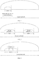
- a base station may configure a carrier bandwidth part for the terminal device from a system frequency resource, and a bandwidth of the carrier bandwidth part may be less than or equal to the bandwidth capability of the terminal device. For example, referring to FIG. 1 , it can be learned that a system bandwidth is greater than a bandwidth capability of a terminal device, and a carrier bandwidth part configured by a base station for the terminal device is less than the bandwidth capability of the terminal device.
- the base station may allocate, to the terminal device, some or all resources in the carrier bandwidth part configured for the terminal device. The resources are used for communication between the base station and the terminal device.
- Scenario 2 Multi-numerology scenario.
- numerologies may be independently set.
- setting performed by a network device may also be understood as configuration.
- a base station may configure a plurality of carrier bandwidth parts on a system frequency resource, and independently configure a numerology for each of the plurality of carrier bandwidth parts, to support a plurality of service types and/or communication scenarios on the system frequency resource. Numerologies of different carrier bandwidth parts may be the same or may be different. For example, referring to FIG. 2 , in a system bandwidth, a base station configures, for a terminal device, two carrier bandwidth parts, which are respectively a BWP 1 and a BWP 2. A numerology of the BWP 1 is a numerology 1, and a numerology of the BWP 2 is a numerology 2.
- the base station may determine, based on a service type and/or a communication scenario that correspond/corresponds to the communication, a numerology A used for the communication, to configure a corresponding carrier bandwidth part for the UE based on the numerology A.
- a numerology of the corresponding carrier bandwidth part is configured as the numerology A.
- the base station may configure a carrier bandwidth part for the terminal device based on a service volume of the terminal device, to reduce power consumption of the terminal device. For example, if the terminal device has no service, the terminal device may be configured to receive control information only in a relatively small carrier bandwidth part. For example, the terminal device is configured to receive the control information in a BWP 1 shown in FIG. 3 , so that radio frequency processing workload and baseband processing workload of the terminal device are reduced, thereby reducing the power consumption of the terminal device. If the terminal device has a relatively small service volume, the base station may configure a carrier bandwidth part having a relatively small bandwidth for the terminal device.
- the base station configures the terminal device to transmit a service in the BWP 1 shown in FIG. 3 , so that radio frequency processing workload and baseband processing workload of the terminal device can be reduced, thereby reducing the power consumption of the terminal device.
- the base station may configure a carrier bandwidth part having a relatively large bandwidth for the terminal device.
- the base station configures the terminal device to transmit a service in a BWP 2 shown in FIG. 3 , so that a higher data transmission rate can be provided.
- the base station may allocate, to the terminal device, some or all resources in the carrier bandwidth part configured for the terminal device. The resources are used for communication between the base station and the terminal device.
- the base station may allocate the carrier bandwidth part to the terminal device.
- the following describes how the base station configures one carrier bandwidth part for the terminal device.
- the configuration of the carrier bandwidth part includes configuring a start resource block (resource block, RB) in frequency domain, a bandwidth (bandwidth, BW), and a corresponding system parameter (numerology) of the carrier bandwidth part.
- the bandwidth may be a quantity of RBs included in the carrier bandwidth part, and the system parameter includes, for example, a subcarrier spacing, a CP, or a subcarrier spacing and a CP.
- the base station may send a first offset, a second offset, and a third offset to the terminal device, to configure one carrier bandwidth part for the terminal device by using the three offsets (offset):
- reference frequency position, the first offset, and a position of the reference point A refer to FIG. 4.
- Different subcarrier spacings have sizes of 2 ⁇ 15 kHz and correspond to indexes of different common RBs, and all subcarriers 0 of common RBs 0 of common RBs corresponding to the different subcarrier spacings correspond to or include the reference point A.
- the common RBs are numbered from the common RB 0 in ascending order of frequencies. After the reference point A is determined, it may be determined that a subcarrier in which the reference point A is located is the subcarrier 0 of the common RB 0 of the common RBs.
- Second offset (offset 2): The terminal device determines, based on the reference point A or the common RB 0 and the second offset relative to the reference point A or the common RB 0, a position of a lowest RB included in the virtual carrier (virtual carrier).
- the second offset refer to FIG. 4 , and a position of the virtual carrier is shown by a block drawn with oblique lines in FIG. 4 .
- Third offset (offset 3) The terminal device determines a position of a lowest RB and a position of a highest RB in the configured BWP based on a size of the configured BWP and an offset (namely, the third offset) between the position of the lowest RB in the configured BWP and the position of the lowest RB in the virtual carrier, for example, a position of the BWP shown in FIG. 4.
- a size of the configured BWP is sent by the base station to the terminal device.
- the base station may configure a plurality of carrier bandwidth parts for the terminal device. However, the base station activates only one of the plurality of carrier bandwidth parts for the terminal device at a same moment, so that the base station and the terminal device transmit a signal with each other in the activated carrier bandwidth part.
- One carrier bandwidth part herein may be understood as one uplink carrier bandwidth part and one downlink carrier bandwidth part. In other words, the base station activates only one uplink carrier bandwidth part and one downlink carrier bandwidth part for the terminal device at a same moment.
- the base station may configure, for the terminal device, a carrier bandwidth part for initial access, activate the carrier bandwidth part, and keep the carrier bandwidth part in an active state.
- the base station configures one or more carrier bandwidth parts for the terminal device by using a radio resource control (radio resource control, RRC) message, and the base station may switch between different carrier bandwidth parts by using an RRC message or downlink control information (downlink control information, DCI), to be specific, activate a new carrier bandwidth part, and deactivate an old carrier bandwidth part.
- RRC radio resource control
- a switching method is that an index of a target active carrier bandwidth part is carried in an RRC message or DCI, to enable the terminal device to switch to the target active carrier bandwidth part.
- the terminal device switches from an original working carrier bandwidth part to a target carrier bandwidth part, the terminal device performs a deactivation operation on the original working carrier bandwidth part, and performs an activation operation on the target carrier bandwidth part to which the terminal device is to switch.
- These operations need to take a time, and the time is used to change a center and/or a size of a radio frequency, resulting in a relatively high switching latency.
- the technical solutions provided in the embodiments of this application may be used in (but not limited to) a communications system having a plurality of subcarrier spacings, for example, an NR system; or may be used in a next-generation communications system or another similar communications system.
- a future service requirement may be considered.
- one terminal device may need a plurality of to-be-activated BWPs simultaneously, and simultaneously transmit a signal in one or more of the BWPs; in this case, that the base station is to activate only one BWP at a moment cannot satisfy the requirement.
- that the base station is to activate a plurality of carrier bandwidth parts for the terminal device includes but is not limited to being applied to at least one of the following three scenarios. In other words, the following three scenarios are several possible application scenarios of the embodiments of this application.
- Scenario 1 In a vehicle to everything (vehicle to everything, V2X) scenario, both an enhanced mobile broadband (enhance mobile broadband, eMBB) service and an ultra-reliable low-latency communication (ultra reliable & low latency communication, URLLC) service are transmitted.
- V2X vehicle to everything
- eMBB enhanced mobile broadband
- URLLC ultra-reliable low-latency communication
- V2X scenarios include a security-related V2X scenario, for example, self-driving, and further include a non-security-related V2X scenario, for example, entertainment with a high mobile data rate.
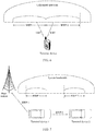
- Some terminal devices need to perform both a self-driving service and an information entertainment activity, to be specific, need to transmit both the URLLC service and the eMBB service, or need to quickly switch from the eMBB service to the URLLC service. As shown in FIG. 5 , a terminal device needs to transmit an eMBB service in a BWP 1, and needs to transmit a URLLC service in a BWP 2.
- Scenario 2 In an unlicensed (unlicensed) spectrum, listen-before-talk (listen-before-talk, LBT) carrier sensing is simultaneously performed in a plurality of BWPs.
- listen-before-talk listen-before-talk
- one carrier may be divided into a plurality of BWPs, and a terminal device separately performs LBT in each BWP, to obtain a higher access opportunity and to more quickly switch to another BWP to perform the LBT.
- one carrier includes a plurality of BWPs, including a BWP 1 and a BWP 2.
- a terminal device may separately perform LBT in the BWP 1 and the BWP 2.
- Scenario 3 Transmission is performed on both an uplink Uu and a sidelink in a V2X scenario.
- the uplink Uu may be understood as that a terminal device sends uplink data to a base station
- the sidelink may be understood as device-to-device (device-to-device, D2D) communication.
- the uplink and the sidelink may be frequency division multiplexed in frequency domain or time domain multiplexed in time domain.
- a BWP 1 may be used to transmit an uplink (UL) road condition report of a terminal device 1 to a base station
- a BWP 2 may be used to transmit security-related information of a sidelink of the terminal device 1 to a terminal device 2.
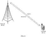
- FIG. 8 includes a network device and a terminal device, and the terminal device is connected to the network device.
- the network device may serve a plurality of terminal devices, and all or some of the plurality of terminal devices may send capability information to the network device by using a method provided in the embodiments of this application.
- the network device in FIG. 8 is, for example, an access network (access network, AN) device, for example, a base station.
- the access network device corresponds to different devices in different systems.
- the access network device may correspond to an eNB in a 4th generation (4G) system, and correspond to an access network device, for example, a gNB, in a 5th generation (5G) system.
- 4G 4th generation
- 5G 5th generation
- FIG. 9A is a flowchart of the method.
- the two communications apparatuses are, for example, a first communications apparatus and a second communications apparatus.
- the first communications apparatus may be a network device or a communications apparatus that can support a network device in implementing a function required for the method, or the first communications apparatus may be a terminal device or a communications apparatus that can support a terminal device in implementing a function required for the method.
- the first communications apparatus may alternatively be another communications apparatus, for example, a chip system.
- the second communications apparatus may be a network device or a communications apparatus that can support a network device in implementing a function required for the method, or the second communications apparatus may be a terminal device or a communications apparatus that can support a terminal device in implementing a function required for the method.
- the second communications apparatus may alternatively be another communications apparatus, for example, a chip system.
- implementations of the first communications apparatus and the second communications apparatus are not limited.
- the first communications apparatus may be a network device, and the second communications apparatus is a terminal device; or both the first communications apparatus and the second communications apparatus are network devices; or both the first communications apparatus and the second communications apparatus are terminal devices; or the first communications apparatus is a network device, and the second communications apparatus is a communications apparatus that can support a terminal device in implementing a function required for the method.
- the network device is a base station.
- the following uses an example in which the method is performed by a network device and a terminal device, that is, an example in which the first communications apparatus is the network device and the second communications apparatus is the terminal device.
- the network device sends a first message in an active first BWP, and the terminal device receives the first message in the active first BWP.
- the first message is used to indicate a new active BWP of the terminal device.
- the new active BWP indicated by the first message is a second BWP is used.
- the second BWP is a BWP in one or more to-be-activated BWPs of the terminal device, and the to-be-activated BWP corresponds to a state configured by the network device for the terminal device, that is, the first message is used to indicate the new active BWP of the terminal device.
- the first message may indicate a to-be-activated BWP or a non-to-be-activated BWP. This is not specifically limited, and an example in which the first message indicates a to-be-activated BWP is merely used in this embodiment.
- the terminal device determines, based on the first message, that the new active BWP of the terminal device is the second BWP, where the second BWP is the BWP in the one or more to-be-activated BWPs of the terminal device, and the to-be-activated BWP corresponds to the state configured by the network device for the terminal device.
- S93 The network device and the terminal device transmit a signal with each other in the second BWP.
- the network device When the network device and the terminal device communicate with each other in the BWP in a wireless manner, the network device manages system frequency resources, and allocates a frequency resource from the system frequency resources to the terminal device, so that the network device and the terminal device can communicate with each other by using the allocated frequency resource.
- the system frequency resource may be a frequency resource that can be managed and allocated by the network device, or may be a frequency resource that can be used for communication between the network device and the terminal device.
- a width of the system frequency resource may be referred to as a bandwidth of the system frequency resource, a carrier bandwidth, a system bandwidth, or a transmission bandwidth.
- the first BWP may be a downlink BWP
- the second BWP may be an uplink BWP or a downlink BWP.
- the network device may send a downlink signal in the second BWP
- the terminal device may receive the downlink signal in the second BWP.
- the downlink signal may include one or more of a physical downlink shared channel (physical downlink shared channel, PDSCH), a synchronization signal, a downlink reference signal, and a physical downlink control channel (physical downlink control channel, PDCCH).
- the terminal device may send an uplink signal in the second BWP, and the network device may receive the uplink signal in the second BWP.
- the uplink signal may include one or more of a physical uplink shared channel (physical uplink shared channel, PDSCH), a physical random access channel (physical random access channel, PRACH), a physical uplink control channel (physical uplink control channel, PUCCH), an acknowledgement (acknowledgement, ACK)/a negative acknowledgement (negative acknowledgement, NACK), and an uplink reference signal.
- the first message may be a message used to instruct the terminal device to switch a BWP.
- the first message may carry an index of the new active BWP.
- the new active BWP may also be referred to as a target active BWP, and a BWP before switching, namely, the first BWP, may also be referred to as a source BWP.
- the terminal device may obtain the index of the new active BWP by parsing the first message. For example, if the first message carries an index of the second BWP, the new active BWP is the second BWP.
- the first message may be implemented by using an RRC message, a media access control (media access control, MAC) control element (control element, CE), or DCI.
- a BWP in the to-be-activated state may also be referred to as a to-be-activated BWP, and a BWP in an active state may also be referred to as an active BWP.
- the to-be-activated BWP corresponds to the state configured by the network device for the terminal device.
- the terminal device is in a radio frequency enabled state for the to-be-activated BWP of the terminal device.
- the active BWP is a BWP that is currently used by the terminal device to listen to a downlink control channel, and/or the active BWP is a BWP that is currently used by the terminal device to send and/or receive a signal
- the to-be-activated BWP may be understood as a BWP in which the terminal device may directly listen to downlink control information, and/or a BWP in which the terminal device may directly send and/or receive a signal, where if the network device indicates, in a current downlink control indication, that a BWP used by the terminal device to monitor a downlink control channel and/or send/receive a signal is the to-be-activated BWP, a latency of switching the BWP by the terminal device is approximately zero; and the terminal device needs to be instructed, by using signaling, to perform an activation operation first and
- the terminal device when switching from an active BWP to a to-be-activated BWP, the terminal device only needs to switch transmission of a signal to the to-be-activated BWP. In this way, the to-be-activated BWP becomes an active BWP.
- a switching latency is very low, and even switching with an approximately zero latency can be implemented. Therefore, the latency of switching the BWP by the terminal device is reduced, and communication quality is improved.
- the terminal device if it is considered that the terminal device is in the radio frequency enabled state for the one or more to-be-activated BWPs of the terminal device, it may be considered that the one or more to-be-activated BWPs includes an active BWP.
- the active BWP is understood as a BWP that can be directly used by the terminal device for signal transmission, for example, the terminal device is in a radio frequency enabled state for the active BWP, in the embodiments of this application, it may be understood that the network device simultaneously activates at least two uplink BWPs and/or downlink BWPs for the terminal device, but the terminal device can transmit signals only on one or more of the at least two active BWPs at a same moment.
- the to-be-activated BWP described in the foregoing paragraph in this embodiment of this application is an active BWP
- the active BWP described in the foregoing paragraph may be understood as a BWP used by the terminal device to transmit a signal at a same moment.
- the second BWP is the BWP in the one or more to-be-activated BWPs of the terminal device, so that the one or more to-be-activated BWPs of the terminal device may include one or more BWPs.
- the following describes how the terminal device determines BWPs to be set as to-be-activated BWPs.
- the network device may further send a second message, and the terminal device may receive the second message.
- the second message may be understood as a configuration message, and is used by the network device to configure one or more BWPs for the terminal device.
- the second message may be implemented by using an RRC message, a MAC CE, or DCI.
- the second message may be transmitted in the first BWP, or may be transmitted in another BWP.
- the terminal device may determine the one or more to-be-activated BWPs of the terminal device based on the second message, that is, determine one or more BWPs that are configured by the network device and that are to be set as the one or more to-be-activated BWPs.
- the one or more to-be-activated BWPs determined by the terminal device may be at least two uplink BWPs and/or at least two downlink BWPs in the one or more BWPs configured by the network device for the terminal device.
- the one or more to-be-activated BWPs determined by the terminal device are at least two uplink BWPs and at least two downlink BWPs in the one or more BWPs configured by the network device for the terminal device; or the one or more to-be-activated BWPs determined by the terminal device are at least two uplink BWPs in the one or more BWPs configured by the network device for the terminal device; or the one or more to-be-activated BWPs determined by the terminal device are at least two downlink BWPs in the one or more BWPs configured by the network device for the terminal device.
- the one or more to-be-activated BWPs determined by the terminal device may be at least one uplink BWP and/or at least one downlink BWP in the one or more BWPs configured by the network device for the terminal device.
- the one or more to-be-activated BWPs determined by the terminal device are at least one uplink BWP and at least one downlink BWP in the one or more BWPs configured by the network device for the terminal device; or the one or more to-be-activated BWPs determined by the terminal device are at least one uplink BWP in the one or more BWPs configured by the network device for the terminal device; or the one or more to-be-activated BWPs determined by the terminal device are at least one downlink BWP in the one or more BWPs configured by the network device for the terminal device.
- the at least two uplink BWPs may be included in the at least one uplink BWP, and the at least two downlink BWP
- the one or more to-be-activated BWPs determined by the terminal device are at least two uplink BWPs and/or at least two downlink BWPs in the one or more BWPs configured by the network device for the terminal device is mainly used for description.
- the network device may configure one or more BWPs for the terminal device in at least one of the one or more carriers.
- the network device configures two BWPs for the terminal device in one carrier.
- the network device configures one BWP for the terminal device in each of two carriers.
- the network device may configure the one or more BWPs for the terminal device by using the second message, or may configure the one or more BWPs for the terminal device by using another message.
- the network device configures the one or more BWPs for the terminal device by using the second message.
- the network device may configure an uplink BWP and/or a downlink BWP for the terminal device.
- the uplink BWP is used by the terminal device to send a signal to the network device
- the downlink BWP is used by the network device to send a signal to the terminal device.
- the one or more BWPs configured by the network device for the terminal device may include N uplink BWPs and/or M downlink BWPs.
- the one or more BWPs configured by the network device for the terminal device includes N uplink BWPs and M downlink BWPs; or the one or more BWPs configured by the network device for the terminal device includes N uplink BWPs; or the one or more BWPs configured by the network device for the terminal device includes M downlink BWPs.
- N and M are positive integers.
- both N and M are integers greater than or equal to 2.
- the one or more BWPs configured by the network device for the terminal device includes the one or more to-be-activated BWPs determined by the terminal device based on the second message.
- a quantity of the one or more BWPs configured by the network device for the terminal device namely, a value of N+M, may be greater than or equal to a quantity of the one or more to-be-activated BWPs determined by the terminal device based on the second message.
- the network device may directly configure the N uplink BWPs and/or the M downlink BWPs for the terminal device; or may group the N uplink BWPs and/or the M downlink BWPs to obtain P BWP groups, and then configure the P BWP groups for the terminal device, where P is a positive integer.
- the network device may configure the P BWP groups for the terminal device by using the second message, or may configure the P BWP groups for the terminal device by using another message. The following separately describes a case in which the network device groups the one or more BWPs or a case in which the network device does not group the one or more BWPs.
- the network device groups the N uplink BWPs and/or the M downlink BWPs that are determined to be configured for the terminal device.
- the network device may use a plurality of grouping manners. Two grouping manners are described in this specification. A person skilled in the art may clearly know that a specific grouping manner is not limited in the embodiments.
- the network device configures N+M BWPs for the terminal device by using P BWP groups; or the network device groups N+M BWPs that are determined to be configured for the terminal device into P BWP groups, where one of the P BWP groups may include at least one uplink BWP and at least one downlink BWP. Quantities of uplink BWPs included in different BWP groups may be the same or may be different, and quantities of downlink BWPs included in different BWP groups may be the same or may be different.
- the network device may perform grouping based on a service type.
- a BWP included in one BWP group is applicable to one type of service.
- the network device determines to configure four uplink BWPs and four downlink BWPs for the terminal device, the network device groups the four uplink BWPs and the four downlink BWPs into two BWP groups, and each BWP group includes two uplink BWPs and two downlink BWPs.
- a BWP included in the first group is applicable to transmission of a first-type service, for example, an eMBB service
- a BWP included in the second group is applicable to transmission of a second-type service, for example, a URLLC service.
- different BWP groups include a same quantity of uplink BWPs
- different BWP groups include a same quantity of downlink BWPs. This is not specifically limited thereto.
- the network device may alternatively perform grouping based on another factor in addition to the service type. This is not specifically limited.
- the network device may further configure at least one to-be-activated uplink BWP and at least one to-be-activated downlink BWP for each of at least one of the BWP groups, and both the at least one to-be-activated uplink BWP and the at least one to-be-activated downlink BWP are included in the one or more to-be-activated BWPs of the terminal device that are determined by the network device.
- the network device may configure, by using the second message, at least one to-be-activated uplink BWP and at least one to-be-activated downlink BWP for at least one of the P BWP groups; or configure, by using another message, at least one to-be-activated uplink BWP and at least one to-be-activated downlink BWP for at least one of the P BWP groups.
- the network device configures the at least two uplink BWPs and/or the at least two downlink BWPs as the to-be-activated BWPs for the terminal device, and both the at least two uplink BWPs and the at least two downlink BWPs belong to the BWPs configured by the network device for the terminal device.
- a total quantity of all to-be-activated uplink BWPs included in at least one BWP group is equal to a total quantity of the at least two uplink BWPs that are configured by the network device and that are used as the to-be-activated BWPs
- a total quantity of all to-be-activated downlink BWPs included in at least one BWP group is equal to a total quantity of the at least two downlink BWPs that are configured by the network device and that are used as the to-be-activated BWPs.
- the network device may configure one to-be-activated uplink BWP and one to-be-activated downlink BWP for each of the at least one of the P BWP groups.
- the network device configures one downlink carrier and one uplink carrier for the terminal device, and the network device configures one or more uplink BWPs for the terminal device in the uplink carrier, and configures one or more downlink BWPs for the terminal device in the downlink carrier.
- the network device further configures a BWP group for the terminal device.
- each BWP group may include the one or more downlink BWPs in the downlink carrier and the one or more uplink BWPs in the uplink carrier.
- the network device may set one of the one or more uplink BWPs as the to-be-activated uplink BWP, and set one of the one or more downlink BWPs as the to-be-activated downlink BWP.
- the network device may configure two to-be-activated uplink BWPs and one to-be-activated downlink BWP for each of the at least one of the P BWP groups.
- the network device configures one downlink carrier, one uplink carrier, and one SUL carrier for the terminal device, and the network device configures one or more uplink BWPs for the terminal device in the uplink carrier, configures one or more uplink BWPs for the terminal device in the SUL carrier, and configures one or more downlink BWPs for the terminal device in the downlink carrier.
- each BWP group may include the one or more downlink BWPs in the downlink carrier, the one or more uplink BWPs in the uplink carrier, and the one or more uplink SUL BWPs in the SUL carrier.
- the network device may set one of the one or more uplink BWPs as the to-be-activated uplink BWP, set one of the one or more uplink SUL BWPs as the to-be-activated uplink BWP, and set one of the one or more downlink BWPs as the to-be-activated downlink BWP. That is, the two to-be-activated uplink BWPs are respectively the uplink BWP and the uplink SUL BWP.
- a quantity of to-be-activated uplink BWPs configured by the network device for one BWP group is less than or equal to a quantity of uplink BWPs included in the BWP group
- a quantity of to-be-activated downlink BWPs configured by the network device for one BWP group is less than or equal to a quantity of downlink BWPs included in the BWP group.
- the BWP group in addition to at least one to-be-activated uplink BWP and at least one to-be-activated downlink BWP, if the BWP group further includes another BWP, the another BWP is a BWP in a non-to-be-activated state, or is referred to as a non-to-be-activated BWP, and the terminal device may be in a radio frequency disabled state for the non-to-be-activated BWP of the terminal device.
- the terminal device may only need to switch transmission of a signal to the to-be-activated BWP without needing to perform any other setting operation. If the terminal device needs to switch from an active BWP to a non-to-be-activated BWP, the terminal device needs to perform an activation operation on the non-to-be-activated BWP, and only after the activation operation, the terminal device can switch transmission of a signal to the non-to-be-activated BWP that is activated. It is clear that a relatively long time is required.
- the at least one to-be-activated uplink BWP and the at least one to-be-activated downlink BWP are configured in the BWP group, so that when switching to the BWP group, the terminal device can directly switch to one of the at least one to-be-activated uplink BWP, or switch to one of the at least one to-be-activated downlink BWP, without needing to perform excessive BWP selection operations, thereby reducing signaling overheads.
- the terminal device may determine the P BWP groups. For example, the terminal device may learn of information about each of the P BWP groups.
- the information about the BWP group is, for example, an identifier or an index of the BWP group.
- the terminal device may further learn of information about all BWPs included in each BWP group, and the information about the BWP includes, for example, an index or an identifier of the BWP.
- a configuration process of the network device may be performed in an initial random access process of the terminal device.
- the second message (or another configuration message) may be transmitted in the initial random access process of the terminal device.
- a configuration process of the network device may be performed after an initial random access process of the terminal device is completed.
- the second message (or another configuration message) may be transmitted after the initial random access process of the terminal device.
- the second message is an RRC message after the initial random access of the terminal device is completed.
- the terminal device after receiving the configuration performed by the network device, the terminal device has the N uplink BWPs and the M downlink BWPs that are configured by the network device, and the BWPs belong to the P BWP groups.
- each of the at least one of the P BWP groups may further include at least one to-be-activated uplink BWP and at least one to-be-activated downlink BWP.
- the to-be-activated uplink BWP is an uplink BWP in the to-be-activated state
- the to-be-activated downlink BWP is a downlink BWP in the to-be-activated state.
- the network device may configure one to-be-activated uplink BWP and one to-be-activated downlink BWP for each of the at least one of the P BWP groups. For example, after the terminal device completes the initial random access, the network device configures four uplink BWPs for the terminal device, where the four uplink BWPs are respectively an uplink BWP 0 to an uplink BWP 3; configures four downlink BWPs, where the four downlink BWPs are respectively a downlink BWP 0 to a downlink BWP 3; and configures two BWP groups for the terminal device, where a BWP group 0 includes the uplink BWP 0, the uplink BWP 1, the downlink BWP 0, and the downlink BWP 1, and a BWP group 1 includes the uplink BWP 2, the downlink BWP 3, the downlink BWP 2, and the downlink BWP 3.
- the network device further configures the uplink BWP 0 as a to-be-activated uplink BWP in the BWP group 0, the downlink BWP 0 as a to-be-activated downlink BWP in the BWP group 0, the uplink BWP 3 as a to-be-activated uplink BWP in the BWP group 1, and the downlink BWP 3 as an active downlink BWP in the BWP group 1.
- the terminal device may determine information about the uplink BWP 0 to the uplink BWP 3, the downlink BWP 0 to the downlink BWP 3, the BWP group 0, and the BWP group 1, and may further determine that the uplink BWP 0, the downlink BWP 0, the uplink BWP 3, and the downlink BWP 3 are all to-be-activated BWPs.
- the network device may configure two to-be-activated uplink BWPs and one to-be-activated downlink BWP for each of the at least one of the P BWP groups. For example, after the terminal device completes the initial random access, the network device configures six uplink BWPs for the terminal device, where four BWPs are configured in an uplink carrier and the four BWPs are respectively an uplink BWP 0 to an uplink BWP 3, and two uplink BWPs are configured in an SUL carrier and the two uplink BWPs are respectively an uplink BWP 4 and an uplink BWP 5; configure four downlink BWPs in a downlink carrier, where the four downlink BWPs are respectively a downlink BWP 0 to a downlink BWP 3; and configures two BWP groups for the terminal device, where a BWP group 0 includes the uplink BWP 0 and the uplink BWP 1 in the uplink carrier,
- the network device further configures the uplink BWP 0 in the uplink carrier and the uplink BWP 4 in the SUL carrier as to-be-activated uplink BWPs in the BWP group 0, the downlink BWP 0 in the downlink carrier as a to-be-activated downlink BWP in the BWP group 0, the uplink BWP 3 in the uplink carrier and the uplink BWP 5 in the SUL carrier as to-be-activated uplink BWPs in the BWP group 1, and the BWP 3 in the downlink carrier as an active downlink BWP in the BWP group 1.
- the terminal device may determine information about the uplink BWP 0 to the uplink BWP 3 in the uplink carrier, the uplink BWP 4 and the uplink BWP 5 in the SUL carrier, the downlink BWP 0 to the downlink BWP 3 in the downlink carrier, the BWP group 0, and the BWP group 1; and may further determine that the uplink BWP 0 in the uplink carrier, the uplink BWP 4 in the SUL carrier, the BWP 0 in the downlink carrier, the uplink BWP 3 in the uplink carrier, the uplink BWP 5 in the SUL carrier, and the downlink BWP 3 in the downlink carrier are all to-be-activated BWPs.
- the terminal device may determine the one or more to-be-activated BWPs of the terminal device based on the second message.
- the network device may further configure the P BWP groups for the terminal device.
- the terminal device may further determine that each of the one or more to-be-activated BWPs of the terminal device belongs to a corresponding BWP group.
- one of the one or more to-be-activated BWPs of the terminal device may be a BWP in one BWP group of the terminal device, the second BWP, or another to-be-activated BWP.
- the BWP group includes K1 uplink BWPs and K 2 downlink BWPs, where both K 1 and K 2 are positive integers, and K 1 and K 2 may be equal to or may not be equal to each other.
- the terminal device may determine that one of the at least one of the P BWP groups may include at least one to-be-activated uplink BWP and at least one to-be-activated downlink BWP.
- the at least one to-be-activated uplink BWP and the at least one to-be-activated downlink BWP are included in the one or more to-be-activated BWPs of the terminal device.
- the at least one to-be-activated uplink BWP and the at least one to-be-activated downlink BWP both belong to the one or more to-be-activated BWPs of the terminal device.
- the BWP group includes K 3 uplink BWPs and K 4 downlink BWPs, where both K 3 and K 4 are positive integers, and K 3 and K 3 may be equal to or may not be equal to each other.
- the BWP group and the foregoing BWP group including the K 1 uplink BWPs and the K 2 downlink BWPs may be a same BWP group.
- the two BWP groups may be different BWP groups.
- K 1 and K 3 may be equal to or may be not equal to each other
- K 4 and K 2 may be equal to or may be not equal to each other.
- the network device when configuring the P BWP groups for the terminal device, may indicate, to the terminal device, that all or some of the BWP groups are configured to be in the to-be-activated state. For example, the network device may indicate, by using the second message or another message, that all or some of the BWP groups of the terminal device are in the to-be-activated state. Setting one BWP group to be in the to-be-activated state may be setting all or some of BWPs included in the BWP group to be in the to-be-activated state.
- the network device further configures at least one to-be-activated uplink BWP and at least one to-be-activated downlink BWP for each of at least one of the P BWP groups.
- the at least one BWP group is set by the network device to be in the to-be-activated state. This is also the same for the terminal device.
- the network device further configures at least one to-be-activated uplink BWP and at least one to-be-activated downlink BWP for each of at least one of the P BWP groups.
- the network device may instruct the terminal device to further set the at least one to-be-activated uplink BWP and the at least one to-be-activated downlink BWP in each of the at least one of the P BWP groups to be in the to-be-activated state.
- the at least one BWP group is set to be in the to-be-activated state.
- the network device sets one to-be-activated uplink BWP and one to-be-activated downlink BWP or sets two to-be-activated uplink BWPs and one to-be-activated downlink BWP in each of at least one of the BWP groups
- the two to-be-activated uplink BWPs include one uplink BWP in the to-be-activated state and one uplink SUL BWP in the to-be-activated state.
- the network device and the terminal device may set at least two BWP groups to be in the to-be-activated state.
- the network device and the terminal device may set the at least one BWP group to be in the to-be-activated state.
- the one or more to-be-activated BWPs of the terminal device are at least two downlink BWPs and/or at least two uplink BWPs in the one or more BWPs of the terminal device.
- the network device sets all the P BWP groups to be in the to-be-activated state.
- the terminal device further sets all the P BWP groups to the to-be-activated state as indicated by the network device, and a manner of setting all the P BWP groups to be in the to-be-activated state is:
- the network sets one to-be-activated uplink BWP and one to-be-activated downlink BWP for each BWP group that is in the P BWP groups and that does not include any uplink SUL BWP, and the network device sets two to-be-activated uplink BWPs and one to-be-activated downlink BWP for each BWP group that is in the P BWP groups and that includes an uplink SUL BWP.
- the two to-be-activated uplink BWPs include an uplink BWP set to be in the to-be-activated state and an uplink SUL BWP set to be in the to-be-activated state.
- the first message sent by the network device may not need to indicate a specific index of the new active BWP, but may indicate information about a BWP group, for example, an identifier or an index of the BWP group.
- the terminal device may directly switch to a to-be-activated uplink BWP and a to-be-activated downlink BWP in the BWP group by default, without needing to determine BWPs to which the terminal device is to switch one by one, thereby facilitating an operation of the terminal device.
- S93 may also be understood as that the terminal device switches to the second BWP, and the network device and the terminal device transmit a signal with each other in the second BWP. Therefore, for a corresponding flowchart in the embodiment shown in FIG. 9A , refer to FIG. 9B .
- S93 includes two processes.
- One process is that the terminal device switches from the first BWP to the second BWP, and the other process is that the terminal device and the network device transmit a signal with each other in the second BWP.
- S91 in FIG. 9B may be the same as S91 in FIG. 9A
- S92 in FIG. 9B may be the same as S92 in FIG. 9A .
- the second BWP also changes from the to-be-activated state to the active state. In other words, the second BWP changes to an active BWP. Therefore, it may also be considered that the terminal device activates the second BWP.
- the network device configures four uplink BWPs for the terminal device, where the four uplink BWPs are respectively an uplink BWP 0 to an uplink BWP 3, configures four downlink BWPs, where the four downlink BWPs are respectively a downlink BWP 0 to a downlink BWP 3, and configures two BWP groups for the terminal device, where a BWP group 0 includes the uplink BWP 0, the uplink BWP 1, the downlink BWP 0, and the downlink BWP 1, and a BWP group 1 includes the uplink BWP 2, the uplink BWP 3, the downlink BWP 2, and the downlink BWP 3.
- the network device configures the uplink BWP 0 as a to-be-activated uplink BWP in the BWP group 0, the downlink BWP 0 as a to-be-activated downlink BWP in the BWP group 0, the uplink BWP 3 as a to-be-activated uplink BWP in the BWP group 1, and the downlink BWP 3 as a to-be-activated downlink BWP in the BWP group 1.
- the terminal device initially works in the BWP group 0, that is, works in the uplink BWP 0 or the downlink BWP 0.
- the network device sends the first message to the terminal device, and a manner of indicating the new active BWP by using the first message is, for example, indicating information about a BWP group.
- the first message indicates an index of the BWP group 1.
- the terminal device determines that a target BWP to which the terminal device is to switch is located in the BWP group 1, and the terminal device switches to the uplink BWP 3 or the downlink BWP 3 in the BWP group 1 by default. It may be considered that an index of the BWP does not need to be additionally obtained from the network device.
- the network device configures one downlink carrier, one uplink carrier, and one SUL carrier for the terminal device, and the network device configures one or more uplink BWPs for the terminal device in the uplink carrier, configures one or more uplink SUL BWPs for the terminal device in the SUL carrier, and configures one or more downlink BWPs for the terminal device in the downlink carrier.
- the network device further configures a BWP group for the terminal device.
- each BWP group may include the one or more downlink BWPs in the downlink carrier, the one or more uplink BWPs in the uplink carrier, and the one or more uplink SUL BWPs in the SUL carrier.
- the network device may set one of the one or more uplink BWPs as the to-be-activated uplink BWP, set one of the one or more uplink SUL BWPs as the to-be-activated uplink BWP, and set one of the one or more downlink BWPs as the to-be-activated downlink BWP. That is, the two to-be-activated uplink BWPs are respectively the uplink BWP and the uplink SUL BWP.
- the network device when instructing the terminal device to switch an uplink BWP, may further indicate an identifier of a carrier.
- the network device may indicate, by using the first message, an identifier of the BWP group and an identifier of a carrier in which a target to-be-activated uplink BWP to which the terminal device is to switch is located, to indicate an uplink carrier in which the target uplink BWP to which the terminal device is to switch is located.
- the network device sets all or some of the P BWP groups to be in the to-be-activated state.
- the network device may keep the BWP groups in the to-be-activated state all the time.
- the network device may alternatively instruct the terminal device to keep the BWP groups in the to-be-activated state all the time. That the BWP group remains in the to-be-activated state may mean that at least one BWP in the BWP group remains in the to-be-activated state, that is, the terminal device is in the radio frequency enabled state for the at least one BWP.
- the network device may further update, in a communication process, the BWP group that is set to be in the to-be-activated state, and the network device may instruct, by using a message, the terminal device to update the BWP group that is set to be in the to-be-activated state.
- the message is, for example, an RRC message, a MAC CE, or DCI.
- the updating may include: setting, to be in the to-be-activated state, a BWP group that is not previously set to be in the to-be-activated state, and/or setting, to be in the non-to-be-activated state, the BWP group that is previously set to be in the to-be-activated state.
- the non-to-be-activated state which is also referred to as an inactive state, in this specification means neither the active state nor the to-be-activated state. If a BWP in this state needs to be activated, an activation operation needs to be performed.
- the first grouping manner described above is applicable to a symmetric spectrum system and an asymmetric spectrum system.
- a frequency domain center position of a to-be-activated uplink BWP is aligned with a frequency domain center position of a to-be-activated downlink BWP, and the to-be-activated uplink BWP and the to-be-activated downlink BWP are a BWP pair. If the terminal device activates one BWP in the BWP pair, the terminal device simultaneously activates the other BWP.
- a downlink BWP of the terminal device is switched from a downlink BWP in a BWP group 1 to a downlink BWP in a BWP group 2, and a corresponding uplink BWP of the terminal device further needs to be switched to an uplink BWP paired with an uplink BWP in the BWP group 2.
- an uplink BWP and a downlink BWP may be independently activated and to be activated.
- a downlink BWP of the terminal device is switched from a downlink BWP in a BWP group 1 to a downlink BWP in a BWP group 2.
- An uplink BWP of the terminal device may be switched or may not be switched, and whether the uplink BWP of the terminal device needs to be switched is determined by the network device. If the uplink BWP of the terminal device also needs to be switched, the network device may further indicate, in the first message, a target uplink BWP to which the terminal device is to switch.
- an uplink BWP and a downlink BWP of the terminal device may be selected for pairing.
- the N uplink BWPs and the M downlink BWPs configured by the network device for the terminal device include a plurality of BWP pairs.
- a downlink BWP 1 and an uplink BWP 1 are a pair
- a downlink BWP 2 and an uplink BWP 2 are a pair.
- an uplink BWP of the terminal device after a downlink BWP of the terminal device is switched from the downlink BWP 1 to the downlink BWP 2, an uplink BWP of the terminal device also needs to be switched from the uplink BWP 1 to the uplink BWP 2.
- the network device may group the downlink BWP 1 and the uplink BWP 1 into one BWP group, and group the downlink BWP 2 and the uplink BWP 2 into one BWP group, and may further set the downlink BWP 2 as a to-be-activated downlink BWP in the BWP group in which the downlink BWP 2 is located, and set the uplink BWP 2 as a to-be-activated uplink BWP in the BWP group in which the uplink BWP 2 is located, so that the terminal device can directly switch the BWP group.
- one BWP group includes both an uplink BWP and a downlink BWP.
- the network device may configure N+M BWPs for the terminal device by using D BWP groups, or the network device may group N+M BWPs that are determined to be configured for the terminal device into D BWP groups.
- One of the D BWP groups may include at least one uplink BWP or at least one downlink BWP.
- the D BWP groups include at least one uplink BWP group and at least one downlink BWP group.
- Quantities of uplink BWPs included in different uplink BWP groups may be the same or may be different, and quantities of downlink BWPs included in different downlink BWP groups may be the same or may be different.
- the network device may directly group all uplink BWPs configured for the terminal device into one BWP group, and group all downlink BWPs configured for the terminal device into one BWP group. For example, the network device determines to configure four uplink BWPs and four downlink BWPs for the terminal device, where the four uplink BWPs are respectively an uplink BWP 0 to an uplink BWP 3, and the four downlink BWPs are respectively a downlink BWP 0 to a downlink BWP 3. The network device may group the four uplink BWPs and the four downlink BWPs into one uplink BWP group and one downlink BWP group.
- a BWP group 0 is the uplink BWP group, including the uplink BWP 0 to the uplink BWP 3; and a BWP group 1 is the downlink BWP group, including the downlink BWP 0 to the downlink BWP 3.
- the network device may alternatively perform grouping based on a service type.
- a BWP included in one BWP group is applicable to one type of service.
- the network device determines to configure four uplink BWPs and four downlink BWPs for the terminal device, where the four uplink BWPs are respectively an uplink BWP 0 to an uplink BWP 3, and the four downlink BWPs are respectively a downlink BWP 0 to a downlink BWP 3.
- the network device groups the four uplink BWPs and the four downlink BWPs into two uplink BWP groups and two downlink BWP groups.
- a BWP group 0 includes the uplink BWP 0 and the uplink BWP 1
- a BWP group 1 includes the uplink BWP 2 and the uplink BWP 3
- a BWP group 2 includes the downlink BWP 0 and the downlink BWP 1
- a BWP group 3 includes the downlink BWP 2 and the downlink BWP 3.
- a BWP included in the BWP group 0 and the BWP group 2 is applicable to transmission of a first-type service, for example, an eMBB service.
- ABWP included in the BWP group 1 and the BWP group 3 is applicable to transmission of a second-type service, for example, a URLLC service.
- different uplink BWP groups include a same quantity of uplink BWPs
- different downlink BWP groups include a same quantity of downlink BWPs. This is not specifically limited thereto.
- the network device may perform grouping based on another factor in addition to the service type. This is not specifically limited.
- the network device may further configure at least one to-be-activated uplink BWP for each of at least one uplink BWP group of the D BWP groups, and/or at least one to-be-activated downlink BWP for each of at least one downlink BWP group of the D BWP groups.
- the network device may configure at least one to-be-activated uplink BWP for each of at least one uplink BWP group of the D BWP groups; or the network device may configure at least one to-be-activated downlink BWP for each of at least one downlink BWP group of the D BWP groups; or the network device may configure at least one to-be-activated uplink BWP for each of at least one uplink BWP group of the D BWP groups, and configure at least one to-be-activated downlink BWP for each of at least one downlink BWP group of the D BWP groups.
- the network device configures at least one to-be-activated uplink BWP for each of at least one uplink BWP group of the D BWP groups, the at least one to-be-activated uplink BWP is included in the one or more to-be-activated BWPs of the terminal device that are determined by the network device. If the network device configures at least one to-be-activated downlink BWP for each of at least one downlink BWP group of the D BWP groups, the at least one to-be-activated downlink BWP is further included in the one or more to-be-activated BWPs of the terminal device that are determined by the network device.
- the network device may configure, by using the second message, at least one to-be-activated uplink BWP for each of at least one uplink BWP group of the D BWP groups, and/or configure at least one to-be-activated downlink BWP for each of at least one downlink BWP group of the D BWP groups; or may configure, by using another message, at least one to-be-activated uplink BWP for each of at least one uplink BWP group of the D BWP groups, and/or configure at least one to-be-activated downlink BWP for each of at least one downlink BWP group of the D BWP groups.
- the network device configures the at least two uplink BWPs and/or the at least two downlink BWPs as the to-be-activated BWPs for the terminal device.
- a total quantity of all to-be-activated uplink BWPs included in at least one uplink BWP group of the D BWP groups is equal to a total quantity of the at least two uplink BWPs that are configured by the network device and that are used as the to-be-activated BWPs
- a total quantity of all to-be-activated downlink BWPs included in at least one downlink BWP group of the D BWP groups is equal to a total quantity of the at least two downlink BWPs that are configured by the network device and that are used as the to-be-activated BWPs.
- all to-be-activated BWPs configured by the network device may be uplink BWPs.
- the network device may configure only at least two uplink BWPs in one uplink BWP group as to-be-activated uplink BWPs, or may configure one or more uplink BWPs in each of a plurality of uplink BWP groups as one or more to-be-activated uplink BWPs.
- all to-be-activated BWPs configured by the network device may be downlink BWPs.
- the network device may configure only at least two downlink BWPs in one downlink BWP group as to-be-activated downlink BWPs, or may configure one or more downlink BWPs in each of a plurality of downlink BWP groups as one or more to-be-activated downlink BWPs.
- to-be-activated BWPs configured by the network device may include an uplink BWP and a downlink BWP.
- the network device may configure at least two uplink BWPs in one uplink BWP group as to-be-activated uplink BWPs, and configure at least two downlink BWPs in one downlink BWP group as to-be-activated downlink BWPs; or configure one or more uplink BWPs in each of a plurality of uplink BWP groups as one or more to-be-activated uplink BWPs, and configure one or more downlink BWPs in each of a plurality of downlink BWP groups as one or more to-be-activated downlink BWPs.
- the network device may configure one to-be-activated uplink BWP for each of at least one uplink BWP group of the D BWP groups, and configure one to-be-activated downlink BWP for each of at least one downlink BWP group of the D BWP groups.
- the network device configures one downlink carrier and one uplink carrier for the terminal device, and the network device configures one or more uplink BWPs in the uplink carrier for the terminal device, and configures one or more downlink BWPs in the downlink carrier for the terminal device.
- the network device further configures a BWP group for the terminal device, for example, configures one or more uplink BWP groups and one or more downlink BWP groups.
- Each uplink BWP group includes at least one uplink BWP
- each downlink BWP group includes at least one downlink BWP.
- the network device may set one uplink BWP in each of the at least one uplink BWP group as the to-be-activated uplink BWP, and the network device may set one downlink BWP in each of the at least one downlink BWP group as the to-be-activated downlink BWP.
- the network device may configure two to-be-activated uplink BWPs for each of at least one uplink BWP group of the D BWP groups, and configure one to-be-activated downlink BWP for each of at least one uplink BWP group of the D BWP groups.
- Each of the at least one uplink BWP group herein may include both an uplink BWP in an uplink carrier and an uplink BWP in an SUL carrier.
- the network device configures one downlink carrier, one uplink carrier, and one SUL carrier for the terminal device, the network device configures one or more uplink BWPs in the uplink carrier for the terminal device, configures one or more downlink BWPs in the downlink carrier for the terminal device, and configures one or more uplink SUL BWPs in the SUL carrier for the terminal device.
- the network device further configures a BWP group for the terminal device, for example, configures one or more uplink BWP groups and one or more downlink BWP groups.
- Each of some uplink BWP groups may include at least one uplink BWP, each of some uplink BWP groups may include at least one uplink BWP and at least one uplink SUL BWP, and each downlink BWP group includes at least one downlink BWP.
- the network device may set an uplink BWP in one uplink carrier in each of the BWP groups as a to-be-activated uplink BWP, and set one uplink SUL BWP in each of the BWP groups as a to-be-activated uplink BWP.
- one uplink BWP group includes two to-be-activated uplink BWPs.
- the network device may further set one downlink BWP in each BWP group as the to-be-activated downlink BWP.
- a quantity of to-be-activated uplink BWPs configured by the network device for one uplink BWP group is less than or equal to a quantity of uplink BWPs included in the uplink BWP group
- a quantity of to-be-activated downlink BWPs configured by the network device for one downlink BWP group is less than or equal to a quantity of downlink BWPs included in the downlink BWP group.
- the another uplink BWP is an uplink BWP in a non-to-be-activated state, or is referred to as a non-to-be-activated uplink BWP.
- the another downlink BWP in addition to at least one to-be-activated downlink BWP, if the downlink BWP group further includes another downlink BWP, the another downlink BWP is a downlink BWP in the non-to-be-activated state, or referred to as a non-to-be-activated downlink BWP.
- the terminal device may be in a radio frequency disabled state for the non-to-be-activated uplink BWP and the non-to-be-activated downlink BWP.
- At least one to-be-activated uplink BWP is configured in one uplink BWP group, so that when switching to the uplink BWP group, the terminal device can directly switch to one of the at least one to-be-activated uplink BWP.
- at least one to-be-activated downlink BWP is configured in one downlink BWP group, so that when switching to the uplink BWP group, the terminal device can directly switch to one of the at least one to-be-activated downlink BWP, and may not need to perform excessive BWP selection operations.
- the terminal device may determine the D BWP groups. For example, the terminal device may determine information about each of the D BWP groups. The information about the BWP group is, for example, an identifier or an index of the BWP group. The terminal device may further learn of information about all BWPs included in each BWP group, and the information about the BWP includes, for example, an index or an identifier of the BWP.
- the terminal device further determines an index or an identifier of the at least one to-be-activated uplink BWP in each of the at least one uplink BWP group of the D BWP groups.
- the terminal device further determines an index or an identifier of the at least one to-be-activated downlink BWP in each of the at least one downlink BWP group of the D BWP groups.
- a configuration process of the network device may be performed in an initial random access process of the terminal device.
- the second message (or another configuration message) may be transmitted in the initial random access process of the terminal device.
- a configuration process of the network device may be performed after an initial random access process of the terminal device is completed.
- the second message (or another configuration message) may be transmitted after the initial random access process of the terminal device is completed.
- the second message is an RRC message transmitted after the initial random access process of the terminal device is completed.
- the configuration process may alternatively occur in any other time period after the initial random access of the terminal device is completed. This is not specifically limited.
- the terminal device may determine N uplink BWPs and M downlink BWPs that are configured by the network device, and the BWPs belong to the D BWP groups. Further, in the D BWP groups, each of at least one uplink BWP group may include at least one to-be-activated uplink BWP; or each of at least one downlink BWP group may include at least one to-be-activated downlink BWP; or each of at least one uplink BWP group may include at least one to-be-activated uplink BWP, and each of at least one downlink BWP group may include at least one to-be-activated downlink BWP.
- the network device may configure one to-be-activated uplink BWP for each of at least one uplink BWP group of the D BWP groups, and configure one to-be-activated downlink BWP for each of at least one downlink BWP group of the D BWP groups.
- the network device configures four uplink BWPs for the terminal device, where the four uplink BWPs are respectively an uplink BWP 0 to an uplink BWP 3; configures four downlink BWPs, where the four downlink BWPs are respectively a downlink BWP 0 to a downlink BWP 3; and configures two uplink BWP groups and two downlink BWP groups for the terminal device, where the two uplink BWP groups are an uplink BWP group 0 and an uplink BWP group 1, the uplink BWP group 0 includes the uplink BWP 0 and the uplink BWP 1, the uplink BWP group 1 includes the uplink BWP 2 and the uplink BWP 3, the two downlink BWP groups are a downlink BWP group 0 and a downlink BWP group 1, the downlink BWP group 0 includes the downlink BWP 0 and the downlink BWP 1,
- the network device further configures the uplink BWP 0 as a to-be-activated uplink BWP in the uplink BWP group 0, the uplink BWP 3 as a to-be-activated uplink BWP in the uplink BWP group 1, the downlink BWP 0 as a to-be-activated downlink BWP in the downlink BWP group 0, and the downlink BWP 3 as a to-be-activated downlink BWP in the downlink BWP group 1.
- the terminal device may determine information about the uplink BWP 0 to the uplink BWP 3, the downlink BWP 0 to the downlink BWP 3, the uplink BWP group 0, the uplink BWP group 1, the downlink BWP group 0, and the downlink BWP group 1, and may further set all of the uplink BWP 0, the downlink BWP 0, the uplink BWP 3, and the downlink BWP 3 as to-be-activated BWPs.
- the network device may configure two to-be-activated uplink BWPs for each of at least one uplink BWP group of the D BWP groups, and configure one to-be-activated downlink BWP for each of at least one uplink BWP group of the D BWP groups.
- Each of the at least one uplink BWP group herein includes both an uplink BWP in an uplink carrier and an uplink BWP in an SUL carrier.
- the network device configures six uplink BWPs for the terminal device, where four BWPs are configured in an uplink carrier and the four BWPs are respectively an uplink BWP 0 to an uplink BWP 3, and two uplink BWPs are configured in an SUL carrier and the two uplink BWPs are respectively an uplink BWP 4 and an uplink BWP 5; configure four downlink BWPs in a downlink carrier, where the four downlink BWPs are respectively a downlink BWP 0 to a downlink BWP 3; and configures two uplink BWP groups and two downlink BWP groups for the terminal device, where the two uplink BWP groups are an uplink BWP group 0 and an uplink BWP group 1, the uplink BWP group 0 includes the uplink BWP 0 and the uplink BWP 1 in the uplink carrier and includes the uplink BWP 4 in the SUL carrier, and the
- the network device further configures the uplink BWP 0 in the uplink carrier and the uplink BWP 4 in the SUL carrier as to-be-activated uplink BWPs in the uplink BWP group 0, the uplink BWP 3 in the uplink carrier and the uplink BWP 5 in the SUL carrier as to-be-activated uplink BWPs in the uplink BWP group 1, the downlink BWP 0 in the downlink carrier as a to-be-activated downlink BWP in the downlink BWP group 0, and the downlink BWP 3 as a to-be-activated downlink BWP in the downlink BWP group 1.
- the terminal device may determine information about the uplink BWP 0 to the uplink BWP 3 in the uplink carrier, the uplink BWP 4 and the uplink BWP 5 in the SUL carrier, the downlink BWP 0 to the downlink BWP 3 in the downlink carrier, the uplink BWP group 0, the uplink BWP group 1, the downlink BWP group 0, and the downlink BWP group 1; and may further determine that the uplink BWP 0 in the uplink carrier, the uplink BWP 4 in the SUL carrier, the uplink BWP 3 in the uplink carrier, the uplink BWP 5 in the SUL carrier, and the downlink BWP 0 and the downlink BWP 3 in the downlink carrier are all to-be-activated BWPs.
- the terminal device may determine the one or more to-be-activated BWPs of the terminal device based on the second message.
- the network device may further configure the D BWP groups for the terminal device.
- the terminal device may further determine that each of the one or more to-be-activated BWPs of the terminal device belongs to a corresponding BWP group.
- one uplink BWP of the one or more to-be-activated BWPs of the terminal device may be a BWP in one uplink BWP group of the terminal device, the second BWP, or another to-be-activated BWP.
- the uplink BWP group includes K 5 uplink BWPs, where K 4 is a positive integer.
- one downlink BWP in the one or more to-be-activated BWPs of the terminal device may be a BWP in one downlink BWP group of the terminal device, the second BWP, or another to-be-activated BWP.
- the downlink BWP group includes K 6 downlink BWPs, where K 4 is a positive integer.
- the uplink BWP group including the K 5 uplink BWPs and the downlink BWP group including the K 4 downlink BWPs may both belong to the D BWP groups, or the uplink BWP group including the K 5 uplink BWPs and the downlink BWP group including the K 4 downlink BWPs may not coexist.
- the D BWP groups include only the uplink BWP group including the K 4 uplink BWPs, and do not include the downlink BWP group including the K 4 downlink BWPs; or the D BWP groups include only the downlink BWP group including the K 4 downlink BWPs, and do not include the uplink BWP group including the K 4 uplink BWPs.
- the terminal device may determine that one of the at least one uplink BWP group of the D BWP groups may include at least one to-be-activated uplink BWP, and the at least one to-be-activated uplink BWP is included in the one or more to-be-activated BWPs of the terminal device.
- the at least one to-be-activated uplink BWP belongs to the one or more to-be-activated BWPs of the terminal device.
- the uplink BWP group includes K 7 uplink BWPs, where K 7 is a positive integer. If the network device further configures at least one to-be-activated downlink BWP for each of at least one downlink BWP group of the D BWP groups, the terminal device may determine that one of the at least one downlink BWP group of the D BWP groups may include at least one to-be-activated downlink BWP, and the at least one to-be-activated downlink BWP is included in the one or more to-be-activated BWPs of the terminal device. In other words, the at least one to-be-activated downlink BWP belongs to the one or more to-be-activated BWPs of the terminal device.
- the downlink BWP group includes K 8 downlink BWPs, where K 8 is a positive integer.
- the uplink BWP group including the K 7 uplink BWPs and the downlink BWP group including the K 7 downlink BWPs may both belong to the D BWP groups, or the uplink BWP group including the K 7 uplink BWPs and the downlink BWP group including the K 8 downlink BWPs may not coexist.
- the D BWP groups include only the uplink BWP group including the K 7 uplink BWPs, and do not include the downlink BWP group including the K 8 downlink BWPs; or the D BWP groups include only the downlink BWP group including the K 8 downlink BWPs, and do not include the uplink BWP group including the K 7 uplink BWPs.
- the network device may indicate, to the terminal device by using the second message or another message, that all or some of the BWP groups configured for the terminal device are in the to-be-activated state.
- Setting one uplink BWP group to be in the to-be-activated state may be setting all or some of uplink BWPs included in the uplink BWP group to be in the to-be-activated state
- setting one downlink BWP group to be in the to-be-activated state may be setting all or some of downlink BWPs included in the downlink BWP group to be in the to-be-activated state.
- the network device further configures at least one to-be-activated uplink BWP for each of at least one uplink BWP group of the D BWP groups. In this case, it may be considered that the at least one uplink BWP group is configured by the network device to be in the to-be-activated state.
- the network device further configures at least one to-be-activated downlink BWP for each of at least one downlink BWP group of the D BWP groups. In this case, it may be considered that the at least one downlink BWP group is configured by the network device to be in the to-be-activated state. This is also the same for the terminal device.
- the network device further configures at least one to-be-activated uplink BWP for each of at least one uplink BWP group of the D BWP groups.
- the terminal device may determine the at least one to-be-activated uplink BWP in each of the at least one uplink BWP group of the D BWP groups.
- the terminal device also determines that the at least one uplink BWP group is in the to-be-activated state.
- the terminal device may determine the at least one to-be-activated downlink BWP in each of the at least one downlink BWP group of the D BWP groups. In other words, the terminal device also determines that the at least one downlink BWP group is in the to-be-activated state.
- the network device may configure at least two uplink BWP groups to be in the to-be-activated state. If the network device configures at least two to-be-activated uplink BWPs for each of at least one uplink BWP group, the network device may set the at least one uplink BWP group to be in the to-be-activated state. In conclusion, it is ensured as much as possible that to-be-activated uplink BWPs of the terminal device are at least two uplink BWPs in the one or more BWPs of the terminal device.
- the network device may set at least two downlink BWP groups to be in the to-be-activated state. If the network device configures at least two to-be-activated downlink BWPs for each of at least one downlink BWP group, the network device may set the at least one downlink BWP group to be in the to-be-activated state. In conclusion, it is ensured as much as possible that to-be-activated downlink BWPs of the terminal device are at least two downlink BWPs in the one or more BWPs of the terminal device.
- the network device sets all the D BWP groups to be in the to-be-activated state.
- the terminal device further determines, as indicated by the network device, that all the D BWP groups are in the to-be-activated state, and a manner of configuring the D BWP groups to be in the to-be-activated state is:
- the network device configures one to-be-activated uplink BWP for each uplink BWP group that is in the D BWP groups and that does not include any uplink BWP in an SUL carrier, and the network device configures two to-be-activated uplink BWPs for each uplink BWP group that is in the D BWP groups and that includes an uplink BWP in an SUL carrier.
- the two to-be-activated uplink BWPs include an uplink BWP that is in the uplink carrier and that is set to be in the to-be-activated state and an uplink BWP that is in the SUL carrier and that is set to be in the to-be-activated state.
- the first message sent by the network device may not need to indicate a specific index of the new active BWP, but may indicate information about a BWP group, for example, an identifier or an index of the BWP group.
- the terminal device may directly switch to a to-be-activated uplink BWP in the BWP group by default, without needing to obtain, from the network device by using additional signaling, BWPs to which the terminal device is to switch to one by one, thereby facilitating an operation of the terminal device.
- S93 may also be understood as that the terminal device switches to the second BWP, and the network device and the terminal device transmit a signal with each other in the second BWP. Therefore, for a corresponding flowchart in the embodiment shown in FIG. 9A , refer to FIG. 9B .
- the second BWP After the terminal device switches to the second BWP, the second BWP also changes from the to-be-activated state to the active state. In other words, the second BWP changes to an active BWP. Therefore, it may also be considered that the terminal device activates the second BWP.
- the network device configures four uplink BWPs for the terminal device, where the four uplink BWPs are respectively an uplink BWP 0 to an uplink BWP 3; configures four downlink BWPs, where the four downlink BWPs are respectively a downlink BWP 0 to a downlink BWP 3; and configures two uplink BWP groups and two downlink BWP groups for the terminal device, where the two uplink BWP groups are an uplink BWP group 0 and an uplink BWP group 1, the uplink BWP group 0 includes the uplink BWP 0 and the uplink BWP 1, the uplink BWP group 1 includes the uplink BWP 2 and the uplink BWP 3, the two downlink BWP groups are a downlink BWP group 0 and a downlink BWP group 1, a downlink BWP group 2 includes the downlink BWP 2 and the downlink BWP 3, and
- the network device further configures the uplink BWP 0 as a to-be-activated uplink BWP in the uplink BWP group 0, the uplink BWP 3 as a to-be-activated uplink BWP in the uplink BWP group 1, the downlink BWP 0 as a to-be-activated downlink BWP in the downlink BWP group 0, and the downlink BWP 3 as a to-be-activated downlink BWP in the downlink BWP group 1.
- the terminal device initially works in the uplink BWP group 0, to be specific, works in the uplink BWP 0.
- the network device sends the first message to the terminal device, and a manner of the first message for indicating the new active BWP is, for example, indicating information about a BWP group.
- the first message indicates an index of the uplink BWP group 1.
- the terminal device determines that a target BWP to which the terminal device is to switch is located in the uplink BWP group 1, and the terminal device switches to the uplink BWP 3 in the uplink BWP group 1 by default, without needing to determine an index of the BWP again.
- the network device configures one downlink carrier, one uplink carrier, and one SUL carrier for the terminal device, and the network device configures one or more uplink BWPs for the terminal device in the uplink carrier, configures one or more uplink BWPs for the terminal device in the SUL carrier, and configures one or more downlink BWPs for the terminal device in the downlink carrier.
- the network device further configures a BWP group for the terminal device.
- each of some or all of uplink BWP groups may include the one or more uplink BWPs in the uplink carrier and the one or more uplink BWPs in the SUL carrier.
- the network device may set one of the one or more uplink BWPs in the uplink carrier as the to-be-activated uplink BWP, and set one of the one or more uplink BWPs in the SUL carriers as the to-be-activated uplink BWP. That is, the two to-be-activated uplink BWPs in the uplink BWP group are respectively the uplink BWP in the uplink carrier and the uplink BWP in the SUL carrier.
- the network device when instructing the terminal device to switch an uplink BWP, may further indicate an identifier of a carrier.
- the network device may indicate, by using the first message, an identifier of the BWP group and an identifier of a carrier in which a target to-be-activated uplink BWP to which the terminal device is to switch is located, to indicate an uplink carrier in which the target uplink BWP to which the terminal device is to switch is located, to distinguish between the uplink BWP in the uplink carrier and the uplink BWP in the SUL carrier.
- the network device After configuring the D BWP groups, the network device sets all or some of the D BWP groups to be in the to-be-activated state. In this case, during communication with the terminal device, the network device may keep the BWP groups in the to-be-activated state all the time. Certainly, the network device may alternatively instruct the terminal device to keep the BWP groups in the to-be-activated state all the time. That the BWP group remains in the to-be-activated state may mean that at least one BWP in the BWP group remains in the to-be-activated state.
- the network device may further update, in a communication process, the BWP group that is set to be in the to-be-activated state, and the network device may instruct, by using a message, the terminal device to update the BWP group that is set to be in the to-be-activated state.
- the message is, for example, an RRC message, a MAC CE, or DCI.
- the updating may include: setting, to be in the to-be-activated state, a BWP group that is not previously set to be in the to-be-activated state, and/or setting, to be in the non-to-be-activated state, the BWP group that is previously set to be in the to-be-activated state.
- setting, to be in the to-be-activated state, a BWP group that is not previously set to be in the to-be-activated state and/or setting, to be in the non-to-be-activated state, the BWP group that is previously set to be in the to-be-activated state.
- the non-to-be-activated state refer to the explanation in the first grouping manner.
- an uplink BWP group and a downlink BWP group that have a same BWP group index may be configured as a BWP group pair.
- indexes may be separately added for the uplink BWP group and the downlink BWP group.
- an index of an uplink BWP group may range from 1 to n
- an index of a downlink BWP group may range from 1 to m, where m and n may be equal to or may not be equal to each other.
- an uplink BWP group and a downlink BWP group that have a same index exist, so that the uplink BWP group and the downlink BWP group that have the same index may be configured as a BWP group pair.
- a downlink BWP of the terminal device is switched from a downlink BWP group 1 to a downlink BWP group 2
- a corresponding uplink BWP of the terminal device further needs to be switched to a to-be-activated uplink BWP in an uplink BWP group 2 that is paired with the downlink BWP group 2.
- an uplink BWP group and a downlink BWP group may be independently activated and to be activated.
- a downlink BWP of the terminal device is switched from a downlink BWP in a BWP group 1 to a downlink BWP in a BWP group 2, and an uplink BWP of the terminal device may be switched or may not be switched, and whether the uplink BWP of the terminal device needs to be switched is determined by the network device. If the uplink BWP of the terminal device also needs to be switched, the network device may further indicate, in the first message, a target uplink BWP to which the terminal device is to switch or a target uplink BWP group to which the terminal device is to switch.
- an uplink BWP group and a downlink BWP group of the terminal device may be selected for pairing.
- an uplink BWP of the terminal device After a downlink BWP of the terminal device is switched from the downlink BWP group 1 to the downlink BWP group 2, an uplink BWP of the terminal device also needs to be switched to the to-be-activated uplink BWP in the uplink BWP group 2 paired with the downlink BWP group 2.
- the network device groups the one or more BWPs configured for the terminal device.
- the network device may alternatively not group the one or more BWPs configured for the terminal device.
- the network device configures the N uplink BWPs and the M downlink BWPs for the terminal device, and the network device may set at least two uplink BWPs thereof as to-be-activated BWPs, or set at least two downlink BWPs thereof as to-be-activated BWPs, or set at least two uplink BWPs thereof as to-be-activated BWPs and set at least two downlink BWPs thereof as to-be-activated BWPs.
- the network device may notify, by using the second message, the terminal device of the N uplink BWPs and the M downlink BWPs, information about the at least two to-be-activated uplink BWPs, and/or information about the at least two to-be-activated downlink BWPs; or the network device may notify the terminal device of the N uplink BWPs and the M downlink BWPs by using another message.
- the terminal device After receiving the configuration performed by the network device, the terminal device determines that the at least two to-be-activated uplink BWPs and/or the at least two to-be-activated downlink BWPs are in the to-be-activated state.
- the network device may further update the to-be-activated BWP.
- the network device may update a to-be-activated BWP configured previously in a process of communicating with the terminal device.
- the updating herein may include: reconfiguring a previously configured to-be-activated BWP as a non-to-be-activated BWP, and/or reconfiguring a previously configured non-to-be-activated BWP as a to-be-activated BWP.
- the network device may send a message, for example, an RRC message, a MAC CE, or DCI, to the terminal device to indicate the to-be-activated BWP to be updated.
- the terminal device may also perform resetting based on the new configuration performed by the network device.
- the network device may further update the BWP group configured to be in the to-be-activated state. For example, if the network device changes the BWP group configured to be in the to-be-activated state from a BWP group 1 to a BWP group 2, the network device may indicate the update of the to-be-activated BWP group to the terminal device by using an RRC message.
- the terminal device may further send a capability message to the network device, and the network device receives the capability message from the terminal device.
- the capability message may carry capability information of the terminal device, so that the network device may configure a BWP for the terminal device based on the capability information of the terminal device. For example, a process in which the terminal device sends the capability message and the network device receives the capability message may occur before the process, described above, in which the network device configures the BWP for the terminal device.
- the capability message sent by the terminal device may indicate a quantity of active BWPs that can be supported by the terminal device, and/or a quantity of to-be-activated BWPs that can be supported by the terminal device.
- the capability message may indicate a quantity of active BWPs that can be supported by the terminal device; or indicate a quantity of to-be-activated BWPs that can be supported by the terminal device; or indicate a quantity of active BWPs that can be supported by the terminal device and a quantity of to-be-activated BWPs that can be supported by the terminal device.
- That the capability message indicates a quantity of active BWPs that can be supported by the terminal device may be understood as that the capability information included in the capability message indicates the quantity of active BWPs that can be supported by the terminal device.
- the capability message indicates a quantity of to-be-activated BWPs that can be supported by the terminal device may also be understood as that the capability information included in the capability message indicates the quantity of to-be-activated BWPs that can be supported by the terminal device.
- the capability message needs to indicate the quantity of active BWPs that can be supported by the terminal device and indicate the quantity of to-be-activated BWPs that can be supported by the terminal device
- the capability information to be sent by the terminal device needs to indicate the quantity of active BWPs that can be supported by the terminal device and indicate the quantity of to-be-activated BWPs that can be supported by the terminal device
- the terminal device needs to send two parts of capability information, one part of the capability information indicates the quantity of active BWPs that can be supported by the terminal device, and the other part of the capability information indicates the quantity of to-be-activated BWPs that can be supported by the terminal device.
- the terminal device may send the two parts of capability information by using one capability message.
- one capability message may indicate the quantity of active BWPs that can be supported by the terminal device and the quantity of to-be-activated BWPs that can be supported by the terminal device.
- the terminal device may separately send the two parts of capability information by using two capability messages.
- one capability message may indicate the quantity of active BWPs that can be supported by the terminal device, and the other capability message may indicate the quantity of to-be-activated BWPs that can be supported by the terminal device.
- the network device may determine, based on the capability message, the quantity of active BWPs that can be supported by the terminal device; or if the capability message is used to indicate the quantity of to-be-activated BWPs that can be supported by the terminal device, the network device may determine, based on the capability message, the quantity of to-be-activated BWPs that can be supported by the terminal device; or if the capability message is used to indicate the quantity of active BWPs that can be supported by the terminal device and the quantity of to-be-activated BWPs that can be supported by the terminal device, the network device may determine, based on the capability message of the terminal device, the quantity of active BWPs that can be supported by the terminal device and the quantity of to-be-activated BWPs that can be supported by the terminal device.
- the terminal device may send the capability information of the terminal device by using one or more of a message 1 (msg1), a message 3 (msg3), an RRC message, or some other uplink messages in the random access process. It may also be understood that the terminal device may send the capability information of the terminal device by using one message. For example, the terminal device sends one piece of capability information, and the capability information is applicable to an uplink and a downlink. Alternatively, the terminal device may send the capability information of the terminal device by using a plurality of messages. For example, the terminal device may separately send uplink capability information and downlink capability information of the terminal device by using different messages.
- a message 1 msg1
- msg3 message 3
- RRC message RRC message
- the message 1 may be a preamble sequence (preamble) sent by the terminal device to the network device in the initial random access process of the terminal device.
- the message 3 may be a third message that is sent to the network device and that is used by the terminal device to determine that a random access response of the network device is sent to the terminal device rather than another terminal device in the initial random access process of the terminal device.
- the quantity of active BWPs that can be supported by the terminal device is a maximum quantity of BWPs in which the terminal device can simultaneously transmit a signal or simultaneously communicate with the network device.
- the quantity of to-be-activated BWPs that can be supported by the terminal device is a maximum quantity of BWPs that can be simultaneously kept in the to-be-activated state by the terminal device.
- the terminal device is in the radio frequency enabled state for the BWPs in the to-be-activated state.
- the capability message sent by the terminal device may indicate that the terminal device can support three to-be-activated uplink BWPs and two to-be-activated downlink BWPs, so that the network device can separately determine an uplink capability and a downlink capability of the terminal device.
- the capability message sent by the terminal device may indicate that the terminal device can support two to-be-activated BWPs. This indicates that the terminal device supports both two to-be-activated uplink BWPs and two to-be-activated downlink BWPs.
- the capability message sent by the terminal device may indicate that the terminal device can support three active uplink BWPs and two active downlink BWPs, so that the network device can separately determine an uplink capability and a downlink capability of the terminal device.
- the capability message sent by the terminal device may indicate that the terminal device can support two active BWPs. This indicates that the terminal device can support both two active uplink BWPs and two active downlink BWPs.
- the terminal device can support simultaneous communication with the network device in only one BWP, even if a plurality of to-be-activated BWPs are simultaneously set for the terminal device, data can be transmitted in only one of the BWPs at a moment (during the data transmission, the BWP is an active BWP, and is no longer the to-be-activated BWP).
- Different to-be-activated BWPs may communicate with each other in a time domain multiplexed manner.
- the terminal device may perform frequency division multiplexed communication in a plurality of to-be-activated BWPs.
- the network device may group the N uplink BWPs and the M downlink BWPs that are configured for the terminal device; or the network device may directly configure one or more BWP groups for the terminal device.
- all the BWP groups configured for the terminal device may be simultaneously activated. Therefore, a quantity of configured BWP groups may be less than or equal to a quantity of to-be-activated BWPs that can be supported by UE, avoid a case in which a quantity of BWPs simultaneously in the to-be-activated state exceeds a capability of the terminal device.
- the quantity of configured BWP groups may be less than or equal to a smaller value in the quantity of to-be-activated uplink BWPs supported by the terminal device and the quantity of to-be-activated downlink BWPs supported by the terminal device. For example, if the terminal device supports two to-be-activated BWPs, the quantity of BWP groups configured by the network device for the terminal device may be less than or equal to 2, and may be specifically 1 or 2.
- the first message is further described.
- an example in which the first message is implemented by using DCI is used.
- the DCI may be a downlink control indication scrambled by using a specific radio network temporary identifier of the terminal device.
- this implementation is applicable to a manner in which the network device groups BWPs configured for the terminal device. This implementation is applicable to the first grouping manner described above, and may further be applicable to the second grouping manner described above.
- the DCI may include one bit field.
- the bit field is referred to as a BWP indicator field, and the BWP indicator field may be used to indicate the new active BWP.
- the terminal device initially works in a to-be-activated uplink BWP and a to-be-activated downlink BWP in a BWP group having a lowest group number. If the network device needs the terminal device to switch to another BWP, the network device may instruct, by using the DCI, the terminal device to switch the BWP.
- a length of the BWP indicator field may be determined based on a quantity of BWPs included in one BWP group of the terminal device and a total quantity of BWP groups of the terminal device.
- the BWP group used to determine the length of the BWP indicator field may be a BWP group in which a quantity of BWPs is greater than or equal to a quantity of BWPs included in another BWP group of the terminal device.
- a quantity of BWPs included in one BWP group may be a quantity of uplink BWPs included in the BWP group.
- the BWP group used to determine the length of the BWP indicator field may be a BWP group in which a quantity of uplink BWPs is greater than or equal to a quantity of uplink BWPs included in another BWP group of the terminal device.
- a quantity of BWPs included in one BWP group may be a quantity of downlink BWPs included in the BWP group.
- the BWP group used to determine the length of the BWP indicator field may be a BWP group in which a quantity of downlink BWPs is greater than or equal to a quantity of downlink BWPs included in another BWP group of the terminal device.
- a quantity of BWPs included in one BWP group may be a total quantity of uplink BWPs and downlink BWPs included in the BWP group.
- the BWP group used to determine the length of the BWP indicator field may be a BWP group in which a total quantity of uplink BWPs and downlink BWPs is greater than or equal to a total quantity of uplink BWPs and downlink BWPs included in another BWP group of the terminal device.
- a quantity of BWPs included in one BWP group is a quantity of uplink BWPs included in the BWP group.
- the terminal device has a total of three BWP groups, which are respectively a BWP group 0 to a BWP group 2.
- the BWP group 0 includes two uplink BWPs
- the BWP group 1 includes four uplink BWPs
- the BWP group 2 includes two uplink BWPs.
- the length of the BWP indicator field may be determined based on the quantity of uplink BWPs included in the BWP group 1 and the total quantity of BWP groups of the terminal device, that is, a length of an uplink BWP indicator field is determined based on the values 4 and 3.
- n BWP is a quantity of uplink BWPs or downlink BWPs included in one BWP group, and may be a maximum value of quantities of uplink BWPs or a maximum value of quantities of downlink BWPs in all BWP groups, or may be a predefined value; or n BWP is a total quantity of uplink BWPs and downlink BWPs included in one BWP group, or may be a maximum value of quantities of uplink BWPs and downlink BWPs in all BWP groups; and n group is a total quantity of BWP groups configured by the network device for the terminal device, a length of an uplink BWP indicator field in uplink DCI may be determined based on the quantity of uplink BWPs in the BWP group, and a length of a downlink
- the first grouping manner described above is used as an example.
- the network device configures four uplink BWPs for the terminal device, where the four uplink BWPs are an uplink BWP 0 to an uplink BWP 3; configures four downlink BWPs, where the four downlink BWPs are a downlink BWP 0 to a downlink BWP 3; and configures two BWP groups for the terminal device, where a BWP group 0 includes the uplink BWP 0, the uplink BWP 1, the downlink BWP 0, and the downlink BWP 1, and a BWP group 1 includes the uplink BWP 2, the uplink BWP 3, the downlink BWP 2, and the downlink BWP 3.
- the network device further configures the uplink BWP 0 as a to-be-activated uplink BWP in the BWP group 0, the downlink BWP 0 as a to-be-activated downlink BWP in the BWP group 0, the uplink BWP 3 as a to-be-activated uplink BWP in the BWP group 1, and the downlink BWP 3 as a to-be-activated downlink BWP in the BWP group 1.
- the length of the BWP indicator field included in the DCI used as the first message is 2. Assuming that the terminal device initially works in the downlink BWP 0, the network device instructs, by using the DCI, the terminal device to switch the BWP.
- Different content may be indicated by using different values of the BWP indicator field included in the DCI. For example, if the value of the BWP indicator field is 00, it indicates that the BWP is not switched, and the DCI may be DCI used for scheduling. If the value of the BWP indicator field is 01, it indicates that the BWP is switched to the downlink BWP 1 in the BWP group 0, and it may be considered that the value 01 of the BWP indicator field indicates an index or an identifier of the BWP group 0, or indicates an index or an identifier of the downlink BWP 1. If the value of the BWP indicator field is 10, it indicates that the BWP is switched to the downlink BWP 2 in the BWP group 1.
- the to-be-activated BWP in the group may further be updated. For example, for the BWP group 1, the to-be-activated BWP may be changed from the downlink BWP 2 to the downlink BWP 3. In this case, when switching from the BWP group 0 to the BWP group 1, the terminal device directly switches to the downlink BWP 3.
- the terminal device may communicate with the network device in the second BWP.
- the terminal device may further keep the first BWP in the to-be-activated state.
- the first BWP may further be included in the one or more to-be-activated BWPs of the terminal device. In this way, if the terminal device needs to switch back to the first BWP again next time, switching with an approximately zero latency may further be implemented.
- the target active BWP may be a to-be-activated BWP, or may be a non-to-be-activated BWP. Further, if the target active BWP is a to-be-activated BWP, after switching to the target active BWP, the terminal device may further keep the first BWP in the to-be-activated state. If the target active BWP is a non-to-be-activated BWP, after switching to the target active BWP, the terminal device may set the first BWP to be in the non-to-be-activated state, that is, deactivate the first BWP.
- the target active BWP is a non-to-be-activated BWP
- a quantity of BWPs simultaneously in the to-be-activated state may be greater than the quantity of to-be-activated BWPs that can be supported by the terminal device. Therefore, if the target active BWP is a non-to-be-activated BWP, after switching to the target active BWP, the terminal device may deactivate the first BWP, so that the terminal device always works based on a normal capability of the terminal device, and a probability that the terminal device is faulty is reduced as much as possible.
- the network device and the terminal device may include a hardware structure and/or a software module, and implement the foregoing functions in a form of the hardware structure, the software module, or a combination of the hardware structure and the software module. Whether a specific function of the foregoing functions is performed by using the hardware structure, the software module, or the combination of the hardware structure and the software module depends on a particular application and a design constraint of the technical solution.
- FIG. 11 is a schematic structural diagram of a communications apparatus 1100.
- the communications apparatus 1100 may be a terminal device, and can implement a function of the terminal device in the method provided in the embodiments of this application.
- the communications apparatus 1100 may alternatively be an apparatus that can support a terminal device in implementing a function of the terminal device in the method provided in the embodiments of this application.
- the communications apparatus 1100 may be a hardware structure, a software module, or a combination of a hardware structure and a software module.
- the communications apparatus 1100 may alternatively be implemented by using a chip system.
- the chip system may include a chip, or may include a chip and another discrete component.
- the communications apparatus 1100 includes a processing module 1101 and a communications module 1102.
- the communications module 1102 may be configured to perform S91 and S93 in the embodiment shown in FIG. 9A or FIG. 9B , and/or configured to support another process of the technology described in this specification.
- the communications module 1102 is used by the communications apparatus 1100 to communicate with another module, which may be a circuit, a component, an interface, a bus, a software module, a transceiver, or any other apparatus that is capable of implementing communication.
- the processing module 1101 is configured to perform S92 in the embodiment shown in FIG. 9A , and may further be configured to perform a step other than information sending and receiving in the embodiment shown in FIG. 9A or FIG. 9B , and/or configured to support another process of the technology described in this specification. All related content of the steps in the foregoing method embodiment may be cited in functional descriptions of the corresponding function modules. Details are not described herein again.
- FIG. 12 is a schematic structural diagram of a communications apparatus 1200.
- the communications apparatus 1200 may be a network device, and can implement a function of the network device in the method provided in the embodiments of this application.
- the communications apparatus 1200 may alternatively be an apparatus that can support a network device in implementing a function of the network device in the method provided in the embodiments of this application.
- the communications apparatus 1200 may be a hardware structure, a software module, or a combination of a hardware structure and a software module.
- the communications apparatus 1200 may alternatively be implemented by using a chip system.
- the communications apparatus 1200 may include a processing module 1201 and a communications module 1202.
- the processing module 1201 may be configured to perform at least one of the steps of determining BWPs to be configured for the terminal device, determining BWP groups to be configured for the terminal device, and determining to-be-activated BWPs to be configured for the terminal device in the embodiment shown in FIG. 9A or FIG. 9B , and may further be configured to perform a step other than information sending and receiving in the embodiment shown in FIG. 9A or FIG. 9B , and/or configured to support another process of the technology described in this specification.
- the communications module 1202 is configured to perform S91 and S93 in the embodiment shown in FIG. 9A or FIG. 9B , and/or configured to support another process of the technology described in this specification.
- the communications module 1202 is used by the communications apparatus 1200 to communicate with another module, which may be a circuit, a component, an interface, a bus, a software module, a transceiver, or any other apparatus that is capable of implementing communication.
- Division into modules in the embodiments of this application is an example, is merely logical function division, and may be other division in an actual implementation.
- function modules in the embodiments of this application may be integrated into one processor, or each of the modules may exist alone physically, or two or more modules may be integrated into one module.
- the integrated module may be implemented in a form of hardware, or may be implemented in a form of a software function module.
- FIG. 13 shows a communications apparatus 1300 according to an embodiment of this application.
- the communications apparatus 1300 may be a terminal device, and can implement a function of the terminal device in the method provided in the embodiments of this application.
- the communications apparatus 1300 may alternatively be an apparatus that can support a terminal device in implementing a function of the terminal device in the method provided in the embodiments of this application.
- the communications apparatus 1300 may be a chip system.
- the communications apparatus 1300 includes at least one processor 1320, configured to implement the function of the terminal device in the method provided in the embodiments of this application or support the communications apparatus 1300 in implementing the function of the terminal device in the method provided in the embodiments of this application.
- the processor 1320 may be configured to perform S92 in the embodiment shown in FIG. 9A .
- the processor 1320 may determine a configuration performed by a network device.
- the processor 1320 may determine a BWP configured by the network device for the terminal device, may further determine a BWP group configured by the network device for the terminal device, and may further determine a to-be-activated BWP configured by the network device for the terminal device.
- BWP configured by the network device for the terminal device
- BWP group configured by the network device for the terminal device
- a to-be-activated BWP configured by the network device for the terminal device.
- the communications apparatus 1300 may further include at least one memory 1330, configured to store a program instruction and/or data.
- the memory 1330 is coupled to the processor 1320.
- the coupling in the embodiments of this application is an indirect coupling or a communication connection between apparatuses, units, or modules, may be in an electrical form, a mechanical form, or another form, and is used for information exchange between the apparatuses, the units, and the modules.
- the processor 1320 may operate in collaboration with the memory 1330.
- the processor 1320 may execute the program instruction stored in the memory 1330. At least one memory 1330 in the at least one memory 1330 may be included in the processor 1320.
- the communications apparatus 1300 may further include a communications interface 1310, configured to communicate with another device through a transmission medium, so that an apparatus used in the communications apparatus 1300 can communicate with the another device.
- the communications interface 1310 is, for example, a transceiver, and is understood as, for example, a radio frequency transceiver component in the communications apparatus 1300, or is understood as an interface of a radio frequency transceiver component in the communications apparatus 1300.
- the another device may be a network device.
- the processor 1320 may send and receive data through the communications interface 1310, and may implement the method performed by the terminal device in the embodiment corresponding to FIG. 9A or FIG. 9B .
- a specific connection medium between the communications interface 1310, the processor 1320, and the memory 1330 is not limited.
- the memory 1330, the processor 1320, and the communications interface 1310 are connected through a bus 1340.
- the bus is represented by a bold line in FIG. 13 .
- a connection manner between other components is merely an example for description, and is not limited thereto.
- the bus may be classified into an address bus, a data bus, a control bus, and the like. For ease of representation, only one thick line is used to represent the bus in FIG. 13 , but this does not mean that there is only one bus or only one type of bus.
- the processor may be a general purpose processor, a digital signal processor, an application-specific integrated circuit, a field programmable gate array or another programmable logic device, a discrete gate or transistor logic device, or a discrete hardware component, and may implement or perform the methods, steps, and logical block diagrams disclosed in the embodiments of this application.
- the general purpose processor may be a microprocessor or any conventional processor or the like. The steps of the method disclosed with reference to the embodiments of this application may be directly performed by a hardware processor, or may be performed by using a combination of hardware in the processor and a software module.
- the memory may be a nonvolatile memory, such as a hard disk drive (hard disk drive, HDD) or a solid-state drive (solid-state drive, SSD), or may be a volatile memory (volatile memory), such as a random access memory (random-access memory, RAM).
- the memory is any other medium that can be configured to carry or store expected program code in a form of an instruction or a data structure and that can be accessed by a computer.
- the memory is not limited thereto.
- the memory in the embodiments of this application may alternatively be a circuit or any other apparatus that can implement a storage function, and is configured to store the program instruction and/or the data.
- FIG. 14 shows a communications apparatus 1400 according to an embodiment of this application.
- the communications apparatus 1400 may be a network device, and can implement a function of the network device in the method provided in the embodiments of this application.
- the communications apparatus 1400 may alternatively be an apparatus that can support a network device in implementing a function of the network device in the method provided in the embodiments of this application.
- the communications apparatus 1400 may be a chip system.
- the communications apparatus 1400 includes at least one processor 1420, configured to implement the function of the network device in the method provided in the embodiments of this application or support the apparatus in implementing the function of the network device in the method provided in the embodiments of this application.
- the processor 1420 may determine a configuration for a terminal device.
- the processor 1420 is configured to determine BWPs to be configured for the terminal device, may further determine BWP groups to be configured for the terminal device, may further determine to-be-activated BWPs to be configured for the terminal device, and may further determine whether the terminal device needs to switch a BWP.
- BWPs to be configured for the terminal device
- BWP groups to be configured for the terminal device
- to-be-activated BWPs to be configured for the terminal device
- the communications apparatus 1400 may further include at least one memory 1430, configured to store a program instruction and/or data.
- the memory 1430 is coupled to the processor 1420.
- the coupling in the embodiments of this application is an indirect coupling or a communication connection between apparatuses, units, or modules, may be in an electrical form, a mechanical form, or another form, and is used for information exchange between the apparatuses, the units, and the modules.
- the processor 1420 may operate in collaboration with the memory 1430.
- the processor 1420 may execute the program instruction stored in the memory 1430. At least one memory 1430 in the at least one memory 1430 may be included in the processor 1420.
- the communications apparatus 1400 may further include a communications interface 1410, configured to communicate with another device through a transmission medium, so that an apparatus used in the communications apparatus 1400 can communicate with the another device.
- the communications interface 1410 is, for example, a transceiver, and is understood as, for example, a radio frequency transceiver component in the communications apparatus 1400, or is understood as an interface of a radio frequency transceiver component in the communications apparatus 1400.
- the another device may be a terminal device.
- the processor 1420 may send and receive data through the communications interface 1410, and may implement the method performed by the terminal device in the embodiment corresponding to FIG. 9A or FIG. 9B .
- a specific connection medium between the communications interface 1410, the processor 1420, and the memory 1430 is not limited in this embodiment of this application.
- the memory 1430, the processor 1420, and the communications interface 1410 are connected through a bus 1440.
- the bus is represented by a bold line in FIG. 14 .
- a connection manner between other components is merely an example for description, and is not limited thereto.
- the bus may be classified into an address bus, a data bus, a control bus, and the like. For ease of representation, only one thick line is used to represent the bus in FIG. 14 , but this does not mean that there is only one bus or only one type of bus.
- An embodiment of this application further provides a computer-readable storage medium, including an instruction.
- the instruction When the instruction is run on a computer, the computer is enabled to perform the method performed by the network device in the embodiments of this application.
- An embodiment of this application further provides a computer-readable storage medium, including an instruction.
- the instruction When the instruction is run on a computer, the computer is enabled to perform the method performed by the terminal device in the embodiments of this application.
- the chip system includes a processor, may further include a memory, and is configured to implement a function of the network device in the foregoing method.
- the chip system may include a chip, or may include a chip and another discrete component.
- the chip system includes a processor, may further include a memory, and is configured to implement a function of the terminal device in the foregoing method.
- the chip system may include a chip, or may include a chip and another discrete component.
- An embodiment of this application provides a communications system.
- the communications system includes the foregoing network device and the foregoing terminal device.
- All or some of the foregoing methods in the embodiments of this application may be implemented by using software, hardware, firmware, or any combination thereof.
- software is used to implement the embodiments, all or some of the embodiments may be implemented in a form of computer program product.
- the computer program product includes one or more computer instructions.
- the computer may be a general purpose computer, a special purpose computer, a computer network, a network device, a user device, or another programmable apparatus.
- the computer instructions may be stored in a computer-readable storage medium or may be transmitted from a computer-readable storage medium to another computer-readable storage medium.
- the computer instructions may be transmitted from a website, computer, server, or data center to another website, computer, server, or data center in a wired (for example, a coaxial cable, an optical fiber, or a digital subscriber line (digital subscriber line, DSL for short)) or wireless (for example, infrared, radio, or microwave) manner.
- the computer-readable storage medium may be any usable medium accessible by a computer, or a data storage device, such as a server or a data center, integrating one or more usable media.
- the usable medium may be a magnetic medium (for example, a floppy disk, a hard disk, or a magnetic tape), an optical medium (for example, a digital video disc (digital video disc, DVD for short)), a semiconductor medium (for example, an SSD), or the like.
- a magnetic medium for example, a floppy disk, a hard disk, or a magnetic tape
- an optical medium for example, a digital video disc (digital video disc, DVD for short)
- a semiconductor medium for example, an SSD
Landscapes
- Engineering & Computer Science (AREA)
- Signal Processing (AREA)
- Computer Networks & Wireless Communication (AREA)
- Mobile Radio Communication Systems (AREA)
Applications Claiming Priority (2)
| Application Number | Priority Date | Filing Date | Title |
|---|---|---|---|
| CN201810623140.2A CN110611957B (zh) | 2018-06-15 | 2018-06-15 | 一种信号传输方法及装置 |
| PCT/CN2019/090165 WO2019237979A1 (zh) | 2018-06-15 | 2019-06-05 | 一种信号传输方法及装置 |
Publications (3)
| Publication Number | Publication Date |
|---|---|
| EP3817480A1 true EP3817480A1 (de) | 2021-05-05 |
| EP3817480A4 EP3817480A4 (de) | 2021-06-30 |
| EP3817480B1 EP3817480B1 (de) | 2023-07-26 |
Family
ID=68842701
Family Applications (1)
| Application Number | Title | Priority Date | Filing Date |
|---|---|---|---|
| EP19818810.4A Active EP3817480B1 (de) | 2018-06-15 | 2019-06-05 | Signalübertragungsverfahren und -vorrichtung |
Country Status (4)
| Country | Link |
|---|---|
| US (1) | US11398885B2 (de) |
| EP (1) | EP3817480B1 (de) |
| CN (1) | CN110611957B (de) |
| WO (1) | WO2019237979A1 (de) |
Cited By (1)
| Publication number | Priority date | Publication date | Assignee | Title |
|---|---|---|---|---|
| EP3806527A4 (de) * | 2018-06-26 | 2022-01-19 | Beijing Xiaomi Mobile Software Co., Ltd. | Verfahren und vorrichtung zum bwp-umschalten und speichermedium |
Families Citing this family (14)
| Publication number | Priority date | Publication date | Assignee | Title |
|---|---|---|---|---|
| WO2020000286A1 (zh) * | 2018-06-28 | 2020-01-02 | Oppo广东移动通信有限公司 | 一种激活带宽部分的方法、终端设备和网络设备 |
| US11026223B2 (en) | 2019-01-24 | 2021-06-01 | Qualcomm Incorporated | Bandwidth part (BWP) selection |
| US20220110121A1 (en) * | 2019-02-22 | 2022-04-07 | Ntt Docomo, Inc. | User apparatus and base station apparatus |
| US11910380B2 (en) * | 2020-07-14 | 2024-02-20 | Qualcomm Incorporated | UE capabilities for supporting complementary bandwidth part operations in wireless communication |
| US20220022209A1 (en) * | 2020-07-14 | 2022-01-20 | Qualcomm Incorporated | Anchor and complementary bandwidth parts for full-duplex operations |
| CN114007225A (zh) * | 2020-07-28 | 2022-02-01 | 北京三星通信技术研究有限公司 | Bwp的分配方法、装置、电子设备及计算机可读存储介质 |
| CN114173322A (zh) * | 2020-09-10 | 2022-03-11 | 华为技术有限公司 | 一种通信方法及装置 |
| US11882605B2 (en) * | 2021-02-01 | 2024-01-23 | Qualcomm Incorporated | Random access channel message repetition indication for retransmission |
| WO2023014131A1 (ko) * | 2021-08-06 | 2023-02-09 | 엘지전자 주식회사 | 무선통신 시스템에서 iab 노드의 동작 방법 및 상기 방법을 이용하는 장치 |
| US11832270B2 (en) | 2021-09-08 | 2023-11-28 | Qualcomm Incorporated | Bandwidth part based uplink and downlink communication in a time resource |
| CN116073969A (zh) * | 2021-11-01 | 2023-05-05 | 中国移动通信有限公司研究院 | 一种数据传输的实现方法、装置和计算机可读存储介质 |
| WO2023102815A1 (en) * | 2021-12-09 | 2023-06-15 | Zte Corporation | Systems and methods for managing frequency resource group based service transmissions |
| CN117837242A (zh) * | 2021-12-09 | 2024-04-05 | 中兴通讯股份有限公司 | 用于管理基于频率资源组的业务传输的系统和方法 |
| WO2023102809A1 (en) * | 2021-12-09 | 2023-06-15 | Zte Corporation | Systems and methods for managing frequency resource group based service transmissions |
Family Cites Families (3)
| Publication number | Priority date | Publication date | Assignee | Title |
|---|---|---|---|---|
| US10159097B2 (en) * | 2016-09-30 | 2018-12-18 | Qualcomm Incorporated | Signaling and determination of slot and mini-slot structure |
| BR112020013867A2 (pt) * | 2018-01-09 | 2020-12-01 | Qualcomm Incorporated | recuperação de feixe em um ambiente de múltiplas partes de largura de banda |
| CN110536422B (zh) * | 2018-05-25 | 2022-05-13 | 华为技术有限公司 | 一种通信方法、装置及系统 |
-
2018
- 2018-06-15 CN CN201810623140.2A patent/CN110611957B/zh active Active
-
2019
- 2019-06-05 EP EP19818810.4A patent/EP3817480B1/de active Active
- 2019-06-05 WO PCT/CN2019/090165 patent/WO2019237979A1/zh unknown
-
2020
- 2020-12-09 US US17/116,632 patent/US11398885B2/en active Active
Cited By (1)
| Publication number | Priority date | Publication date | Assignee | Title |
|---|---|---|---|---|
| EP3806527A4 (de) * | 2018-06-26 | 2022-01-19 | Beijing Xiaomi Mobile Software Co., Ltd. | Verfahren und vorrichtung zum bwp-umschalten und speichermedium |
Also Published As
| Publication number | Publication date |
|---|---|
| EP3817480B1 (de) | 2023-07-26 |
| US20210119745A1 (en) | 2021-04-22 |
| US11398885B2 (en) | 2022-07-26 |
| CN110611957B (zh) | 2021-09-07 |
| WO2019237979A1 (zh) | 2019-12-19 |
| CN110611957A (zh) | 2019-12-24 |
| EP3817480A4 (de) | 2021-06-30 |
Similar Documents
| Publication | Publication Date | Title |
|---|---|---|
| US11398885B2 (en) | Signal transmission method and apparatus | |
| US11490370B2 (en) | Information transmission method and apparatus | |
| US11985688B2 (en) | Transmission direction configuration method, device, and system | |
| WO2019128680A1 (zh) | 一种确定bwp状态的方法、设备及系统 | |
| EP3627733A1 (de) | Kommunikationsverfahren, netzwerkvorrichtung und endgerätevorrichtung | |
| EP2757849B1 (de) | Verfahren und vorrichtung für mehrträgerplanung | |
| US11936596B2 (en) | Bandwidth part processing method and apparatus | |
| WO2019029348A1 (zh) | 数据传输方法、终端和基站 | |
| CN113424618B (zh) | 一种通信方法、装置及计算机可读存储介质 | |
| CN111953464A (zh) | 频域资源的处理方法、装置及系统 | |
| US20210336755A1 (en) | Communications method and apparatus | |
| EP3823385A1 (de) | Kommunikationsverfahren und -vorrichtung | |
| US11979760B2 (en) | Physical downlink control channel monitoring scaling | |
| EP4354997A1 (de) | Signalübertragungsverfahren und -vorrichtung | |
| US20230188299A1 (en) | Resource configuration method and apparatus | |
| WO2024011632A1 (zh) | 资源配置方法、装置、设备及存储介质 | |
| WO2022082729A1 (en) | Enhancement to bandwidth part (bwp) switching for secondary cell (scell) | |
| EP4171141A1 (de) | Kommunikationsverfahren und -vorrichtung |
Legal Events
| Date | Code | Title | Description |
|---|---|---|---|
| STAA | Information on the status of an ep patent application or granted ep patent |
Free format text: STATUS: THE INTERNATIONAL PUBLICATION HAS BEEN MADE |
|
| STAA | Information on the status of an ep patent application or granted ep patent |
Free format text: STATUS: THE INTERNATIONAL PUBLICATION HAS BEEN MADE |
|
| PUAI | Public reference made under article 153(3) epc to a published international application that has entered the european phase |
Free format text: ORIGINAL CODE: 0009012 |
|
| STAA | Information on the status of an ep patent application or granted ep patent |
Free format text: STATUS: REQUEST FOR EXAMINATION WAS MADE |
|
| 17P | Request for examination filed |
Effective date: 20201208 |
|
| AK | Designated contracting states |
Kind code of ref document: A1 Designated state(s): AL AT BE BG CH CY CZ DE DK EE ES FI FR GB GR HR HU IE IS IT LI LT LU LV MC MK MT NL NO PL PT RO RS SE SI SK SM TR |
|
| A4 | Supplementary search report drawn up and despatched |
Effective date: 20210601 |
|
| RIC1 | Information provided on ipc code assigned before grant |
Ipc: H04L 5/00 20060101ALI20210526BHEP Ipc: H04W 72/04 20090101AFI20210526BHEP |
|
| DAV | Request for validation of the european patent (deleted) | ||
| DAX | Request for extension of the european patent (deleted) | ||
| GRAP | Despatch of communication of intention to grant a patent |
Free format text: ORIGINAL CODE: EPIDOSNIGR1 |
|
| STAA | Information on the status of an ep patent application or granted ep patent |
Free format text: STATUS: GRANT OF PATENT IS INTENDED |
|
| RIC1 | Information provided on ipc code assigned before grant |
Ipc: H04L 5/00 20060101ALI20230208BHEP Ipc: H04W 72/04 20090101AFI20230208BHEP |
|
| RIC1 | Information provided on ipc code assigned before grant |
Ipc: H04L 5/00 20060101ALI20230223BHEP Ipc: H04W 72/04 20090101AFI20230223BHEP |
|
| INTG | Intention to grant announced |
Effective date: 20230306 |
|
| GRAS | Grant fee paid |
Free format text: ORIGINAL CODE: EPIDOSNIGR3 |
|
| GRAA | (expected) grant |
Free format text: ORIGINAL CODE: 0009210 |
|
| STAA | Information on the status of an ep patent application or granted ep patent |
Free format text: STATUS: THE PATENT HAS BEEN GRANTED |
|
| AK | Designated contracting states |
Kind code of ref document: B1 Designated state(s): AL AT BE BG CH CY CZ DE DK EE ES FI FR GB GR HR HU IE IS IT LI LT LU LV MC MK MT NL NO PL PT RO RS SE SI SK SM TR |
|
| REG | Reference to a national code |
Ref country code: CH Ref legal event code: EP |
|
| REG | Reference to a national code |
Ref country code: DE Ref legal event code: R096 Ref document number: 602019033701 Country of ref document: DE |
|
| REG | Reference to a national code |
Ref country code: IE Ref legal event code: FG4D |
|
| REG | Reference to a national code |
Ref country code: LT Ref legal event code: MG9D |
|
| REG | Reference to a national code |
Ref country code: NL Ref legal event code: MP Effective date: 20230726 |
|
| REG | Reference to a national code |
Ref country code: AT Ref legal event code: MK05 Ref document number: 1593427 Country of ref document: AT Kind code of ref document: T Effective date: 20230726 |
|
| PG25 | Lapsed in a contracting state [announced via postgrant information from national office to epo] |
Ref country code: NL Free format text: LAPSE BECAUSE OF FAILURE TO SUBMIT A TRANSLATION OF THE DESCRIPTION OR TO PAY THE FEE WITHIN THE PRESCRIBED TIME-LIMIT Effective date: 20230726 |
|
| PG25 | Lapsed in a contracting state [announced via postgrant information from national office to epo] |
Ref country code: GR Free format text: LAPSE BECAUSE OF FAILURE TO SUBMIT A TRANSLATION OF THE DESCRIPTION OR TO PAY THE FEE WITHIN THE PRESCRIBED TIME-LIMIT Effective date: 20231027 |
|
| PG25 | Lapsed in a contracting state [announced via postgrant information from national office to epo] |
Ref country code: IS Free format text: LAPSE BECAUSE OF FAILURE TO SUBMIT A TRANSLATION OF THE DESCRIPTION OR TO PAY THE FEE WITHIN THE PRESCRIBED TIME-LIMIT Effective date: 20231126 |
|
| PG25 | Lapsed in a contracting state [announced via postgrant information from national office to epo] |
Ref country code: SE Free format text: LAPSE BECAUSE OF FAILURE TO SUBMIT A TRANSLATION OF THE DESCRIPTION OR TO PAY THE FEE WITHIN THE PRESCRIBED TIME-LIMIT Effective date: 20230726 Ref country code: RS Free format text: LAPSE BECAUSE OF FAILURE TO SUBMIT A TRANSLATION OF THE DESCRIPTION OR TO PAY THE FEE WITHIN THE PRESCRIBED TIME-LIMIT Effective date: 20230726 Ref country code: PT Free format text: LAPSE BECAUSE OF FAILURE TO SUBMIT A TRANSLATION OF THE DESCRIPTION OR TO PAY THE FEE WITHIN THE PRESCRIBED TIME-LIMIT Effective date: 20231127 Ref country code: NO Free format text: LAPSE BECAUSE OF FAILURE TO SUBMIT A TRANSLATION OF THE DESCRIPTION OR TO PAY THE FEE WITHIN THE PRESCRIBED TIME-LIMIT Effective date: 20231026 Ref country code: LV Free format text: LAPSE BECAUSE OF FAILURE TO SUBMIT A TRANSLATION OF THE DESCRIPTION OR TO PAY THE FEE WITHIN THE PRESCRIBED TIME-LIMIT Effective date: 20230726 Ref country code: LT Free format text: LAPSE BECAUSE OF FAILURE TO SUBMIT A TRANSLATION OF THE DESCRIPTION OR TO PAY THE FEE WITHIN THE PRESCRIBED TIME-LIMIT Effective date: 20230726 Ref country code: IS Free format text: LAPSE BECAUSE OF FAILURE TO SUBMIT A TRANSLATION OF THE DESCRIPTION OR TO PAY THE FEE WITHIN THE PRESCRIBED TIME-LIMIT Effective date: 20231126 Ref country code: HR Free format text: LAPSE BECAUSE OF FAILURE TO SUBMIT A TRANSLATION OF THE DESCRIPTION OR TO PAY THE FEE WITHIN THE PRESCRIBED TIME-LIMIT Effective date: 20230726 Ref country code: GR Free format text: LAPSE BECAUSE OF FAILURE TO SUBMIT A TRANSLATION OF THE DESCRIPTION OR TO PAY THE FEE WITHIN THE PRESCRIBED TIME-LIMIT Effective date: 20231027 Ref country code: FI Free format text: LAPSE BECAUSE OF FAILURE TO SUBMIT A TRANSLATION OF THE DESCRIPTION OR TO PAY THE FEE WITHIN THE PRESCRIBED TIME-LIMIT Effective date: 20230726 Ref country code: AT Free format text: LAPSE BECAUSE OF FAILURE TO SUBMIT A TRANSLATION OF THE DESCRIPTION OR TO PAY THE FEE WITHIN THE PRESCRIBED TIME-LIMIT Effective date: 20230726 |
|
| PG25 | Lapsed in a contracting state [announced via postgrant information from national office to epo] |
Ref country code: PL Free format text: LAPSE BECAUSE OF FAILURE TO SUBMIT A TRANSLATION OF THE DESCRIPTION OR TO PAY THE FEE WITHIN THE PRESCRIBED TIME-LIMIT Effective date: 20230726 |
|
| PG25 | Lapsed in a contracting state [announced via postgrant information from national office to epo] |
Ref country code: ES Free format text: LAPSE BECAUSE OF FAILURE TO SUBMIT A TRANSLATION OF THE DESCRIPTION OR TO PAY THE FEE WITHIN THE PRESCRIBED TIME-LIMIT Effective date: 20230726 |
|
| PG25 | Lapsed in a contracting state [announced via postgrant information from national office to epo] |
Ref country code: SM Free format text: LAPSE BECAUSE OF FAILURE TO SUBMIT A TRANSLATION OF THE DESCRIPTION OR TO PAY THE FEE WITHIN THE PRESCRIBED TIME-LIMIT Effective date: 20230726 Ref country code: RO Free format text: LAPSE BECAUSE OF FAILURE TO SUBMIT A TRANSLATION OF THE DESCRIPTION OR TO PAY THE FEE WITHIN THE PRESCRIBED TIME-LIMIT Effective date: 20230726 Ref country code: ES Free format text: LAPSE BECAUSE OF FAILURE TO SUBMIT A TRANSLATION OF THE DESCRIPTION OR TO PAY THE FEE WITHIN THE PRESCRIBED TIME-LIMIT Effective date: 20230726 Ref country code: EE Free format text: LAPSE BECAUSE OF FAILURE TO SUBMIT A TRANSLATION OF THE DESCRIPTION OR TO PAY THE FEE WITHIN THE PRESCRIBED TIME-LIMIT Effective date: 20230726 Ref country code: DK Free format text: LAPSE BECAUSE OF FAILURE TO SUBMIT A TRANSLATION OF THE DESCRIPTION OR TO PAY THE FEE WITHIN THE PRESCRIBED TIME-LIMIT Effective date: 20230726 Ref country code: CZ Free format text: LAPSE BECAUSE OF FAILURE TO SUBMIT A TRANSLATION OF THE DESCRIPTION OR TO PAY THE FEE WITHIN THE PRESCRIBED TIME-LIMIT Effective date: 20230726 Ref country code: SK Free format text: LAPSE BECAUSE OF FAILURE TO SUBMIT A TRANSLATION OF THE DESCRIPTION OR TO PAY THE FEE WITHIN THE PRESCRIBED TIME-LIMIT Effective date: 20230726 |