EP3817352A1 - Imaging device and line-variation-noise-reducing device - Google Patents
Imaging device and line-variation-noise-reducing device Download PDFInfo
- Publication number
- EP3817352A1 EP3817352A1 EP18924114.4A EP18924114A EP3817352A1 EP 3817352 A1 EP3817352 A1 EP 3817352A1 EP 18924114 A EP18924114 A EP 18924114A EP 3817352 A1 EP3817352 A1 EP 3817352A1
- Authority
- EP
- European Patent Office
- Prior art keywords
- value
- line
- calculation unit
- unit
- detection
- Prior art date
- Legal status (The legal status is an assumption and is not a legal conclusion. Google has not performed a legal analysis and makes no representation as to the accuracy of the status listed.)
- Granted
Links
Images



Classifications
-
- G—PHYSICS
- G06—COMPUTING OR CALCULATING; COUNTING
- G06T—IMAGE DATA PROCESSING OR GENERATION, IN GENERAL
- G06T5/00—Image enhancement or restoration
- G06T5/70—Denoising; Smoothing
-
- H—ELECTRICITY
- H04—ELECTRIC COMMUNICATION TECHNIQUE
- H04N—PICTORIAL COMMUNICATION, e.g. TELEVISION
- H04N25/00—Circuitry of solid-state image sensors [SSIS]; Control thereof
- H04N25/60—Noise processing, e.g. detecting, correcting, reducing or removing noise
- H04N25/67—Noise processing, e.g. detecting, correcting, reducing or removing noise applied to fixed-pattern noise, e.g. non-uniformity of response
- H04N25/671—Noise processing, e.g. detecting, correcting, reducing or removing noise applied to fixed-pattern noise, e.g. non-uniformity of response for non-uniformity detection or correction
- H04N25/677—Noise processing, e.g. detecting, correcting, reducing or removing noise applied to fixed-pattern noise, e.g. non-uniformity of response for non-uniformity detection or correction for reducing the column or line fixed pattern noise
-
- G—PHYSICS
- G06—COMPUTING OR CALCULATING; COUNTING
- G06T—IMAGE DATA PROCESSING OR GENERATION, IN GENERAL
- G06T5/00—Image enhancement or restoration
- G06T5/20—Image enhancement or restoration using local operators
-
- G—PHYSICS
- G06—COMPUTING OR CALCULATING; COUNTING
- G06T—IMAGE DATA PROCESSING OR GENERATION, IN GENERAL
- G06T5/00—Image enhancement or restoration
- G06T5/50—Image enhancement or restoration using two or more images, e.g. averaging or subtraction
-
- H—ELECTRICITY
- H04—ELECTRIC COMMUNICATION TECHNIQUE
- H04N—PICTORIAL COMMUNICATION, e.g. TELEVISION
- H04N23/00—Cameras or camera modules comprising electronic image sensors; Control thereof
- H04N23/70—Circuitry for compensating brightness variation in the scene
- H04N23/745—Detection of flicker frequency or suppression of flicker wherein the flicker is caused by illumination, e.g. due to fluorescent tube illumination or pulsed LED illumination
-
- H—ELECTRICITY
- H04—ELECTRIC COMMUNICATION TECHNIQUE
- H04N—PICTORIAL COMMUNICATION, e.g. TELEVISION
- H04N23/00—Cameras or camera modules comprising electronic image sensors; Control thereof
- H04N23/80—Camera processing pipelines; Components thereof
- H04N23/81—Camera processing pipelines; Components thereof for suppressing or minimising disturbance in the image signal generation
-
- H—ELECTRICITY
- H04—ELECTRIC COMMUNICATION TECHNIQUE
- H04N—PICTORIAL COMMUNICATION, e.g. TELEVISION
- H04N5/00—Details of television systems
- H04N5/14—Picture signal circuitry for video frequency region
- H04N5/21—Circuitry for suppressing or minimising disturbance, e.g. moiré or halo
-
- G—PHYSICS
- G06—COMPUTING OR CALCULATING; COUNTING
- G06T—IMAGE DATA PROCESSING OR GENERATION, IN GENERAL
- G06T2207/00—Indexing scheme for image analysis or image enhancement
- G06T2207/10—Image acquisition modality
- G06T2207/10016—Video; Image sequence
Definitions
- the present invention relates to an image capturing device and a line fluctuation noise reduction device.
- An image pickup device e.g., image sensor captures an image of a subject by using a plurality of detection elements arranged two-dimensionally and thereby successively outputs pixel values of a plurality of pixels corresponding to the plurality of detection elements as an image signal.
- This image signal can contain line fluctuation noise as level fluctuation in the pixel values of each horizontal scan line due to a noise component in each horizontal scan line (see Patent Reference 1, for example).
- the line fluctuation noise causes flicker in the image and lowers visibility of the image.
- a method for suppressing the line fluctuation noise there is a method of correcting the image signal so that the average value of the pixel values in each horizontal scan line in the image signal becomes constant.
- the difference between the average value of the pixel values of all pixels in one horizontal scan line and the average value of the pixel values of all pixels in the same horizontal scan line in a frame one frame earlier, or a line fluctuation value as the average value of the difference between the pixel value of each pixel in one horizontal scan line and the pixel value of the same pixel in the same horizontal scan line in a frame one frame earlier, is used as a correction value.
- Patent Reference 1 Japanese Patent No. 4749397
- the line fluctuation value calculated when the subject includes a moving part contains a movement component as a fluctuation component not due to the noise component in each horizontal scan line, namely, as a fluctuation component due to the moving part. Accordingly, there is a problem in that the line fluctuation noise cannot be reduced appropriately if the image signal is corrected by using the line fluctuation value as the correction value.
- An object of the present invention which has been made to resolve the above-described problem with the conventional technology, is to provide an image capturing device capable of appropriately reducing the line fluctuation noise even when a moving part is included in the subject and a line fluctuation noise reduction device capable of appropriately reducing the line fluctuation noise even when a moving part is included in a detection target.
- An image capturing device includes: an image capturing unit that includes a plurality of detection elements arranged two-dimensionally in a horizontal scan direction and a vertical direction, captures an image of a subject, and thereby outputs pixel values of a plurality of pixels corresponding to the plurality of detection elements; a pixel value fluctuation amount calculation unit that calculates a pixel value fluctuation amount as a fluctuation amount of each of the pixel values in a time direction; a line fluctuation amount calculation unit that calculates a line fluctuation amount as an average value of N pixel value fluctuation amounts of N pixels in a partial line where N is an integer smaller than a total number of pixels in a horizontal scan line and the partial line is a range of N consecutive pixels in the horizontal scan line; a variance value calculation unit that calculates a variance value of the N pixel value fluctuation amounts from the N pixel value fluctuation amounts and the line fluctuation amount; a movement adaptive weight determination unit that calculates a movement adaptive weight based on the variance value;
- a line fluctuation noise reduction device is a device that receives a detection signal outputted from a detection unit including a plurality of detection elements arranged two-dimensionally in a horizontal scan direction and a vertical direction, detecting a physical quantity of a detection target, and thereby outputting detection values of a plurality of detection points corresponding to the plurality of detection elements, including: a detection value fluctuation amount calculation unit that calculates a detection value fluctuation amount as a fluctuation amount of each of the detection values in a time direction; a line fluctuation amount calculation unit that calculates a line fluctuation amount as an average value of N detection value fluctuation amounts of N detection points in a partial line where N is an integer smaller than a total number of detection points in a horizontal scan line and the partial line is a range of N consecutive detection points in the horizontal scan line; a variance value calculation unit that calculates a variance value of the N detection value fluctuation amounts from the N detection value fluctuation amounts and the line fluctuation amount; a movement adaptive weight determination unit that
- the line fluctuation noise can be reduced appropriately while inhibiting influence on the movement component of the image signal.
- the line fluctuation noise reduction device According to the present invention, even when a moving part is included in the detection target, the line fluctuation noise can be reduced appropriately while inhibiting influence on the movement component of the detection signal.
- Fig. 1 is a block diagram schematically showing a configuration of an image capturing device 1 according to a first embodiment of the present invention.
- the image capturing device 1 according to the first embodiment includes an image pickup device 20 as an image capturing unit and a line fluctuation noise reduction unit 10 as a line fluctuation noise reduction device.
- the image pickup device 20 includes a plurality of detection elements arranged two-dimensionally in a horizontal scan direction and a vertical direction, captures an image of a subject by using the plurality of detection elements, and thereby outputs pixel values of a plurality of pixels corresponding to the plurality of detection elements as an image signal.
- the image signal is represented as Yin.
- Each pixel value forming the image signal Yin is represented as Yin(i).
- the pixel value of the i-th pixel in a frame that is the F-th (hereinafter referred to also as an "F-th frame”) is represented as Yin(i) [F].
- i in round brackets () is a positive integer indicating the number of a pixel in a certain frame.
- F in square brackets is a positive integer indicating a frame number.
- the line fluctuation noise reduction unit 10 is a signal processing circuit, for example. As shown in Fig. 1 , the line fluctuation noise reduction unit 10 includes a delay unit 101, a pixel value fluctuation amount calculation unit 102, a line fluctuation amount calculation unit 103, a variance value calculation unit 104, a screen variance value average calculation unit 105, a target reference variance value calculation unit 106, a reference variance value calculation unit 107, a scaling factor calculation unit 108, a variance value index calculation unit 109, a movement adaptive weight calculation unit 110, a correction amount calculation unit 111, a line fluctuation noise correction unit 112 and a frame delay unit 113.
- the screen variance value average calculation unit 105, the target reference variance value calculation unit 106, the reference variance value calculation unit 107, the scaling factor calculation unit 108, the variance value index calculation unit 109 and the movement adaptive weight calculation unit 110 constitute a movement adaptive weight determination unit 114.
- the pixel value fluctuation amount calculation unit 102 calculates a pixel value fluctuation amount d(i) as a fluctuation amount of each of the pixel values in a time direction.
- the line fluctuation amount calculation unit 103 calculates a line fluctuation amount ave(i) as the average value of N pixel value fluctuation amounts of the N pixels in the partial line.
- the line fluctuation amount corresponding to the pixel value of the i-th pixel in the F-th frame is represented as ave(i)[F]. Concrete examples of the partial line will be described later.
- the variance value calculation unit 104 calculates a variance value var(i) of the N pixel value fluctuation amounts from the N pixel value fluctuation amounts of the N pixels in the partial line and the line fluctuation amount.
- the variance value var(i) of the N pixel value fluctuation amounts calculated from the N pixel value fluctuation amounts of the N pixels in the F-th frame and the line fluctuation amount ave(i)[F] corresponding to the pixel value of the i-th pixel in the F-th frame is represented as var(i)[F].
- the movement adaptive weight determination unit 114 calculates a movement adaptive weight w(i) based on the variance value var(i).
- the movement adaptive weight w(i) corresponding to the pixel value of the i-th pixel in the F-th frame is represented as w(i) [F].
- the movement adaptive weight w(i)[F] takes on a small value when there is a lot of moving parts included in the subject, and the movement adaptive weight w(i)[F] takes on a large value when there is few moving parts included in the subject.
- the correction amount calculation unit 111 calculates a line fluctuation noise correction amount c_lfn(i), corresponding to each of the pixel values outputted from the image capturing unit 20, from the line fluctuation amount ave(i) and the movement adaptive weight w(i).
- the line fluctuation noise correction amount corresponding to the pixel value of the i-th pixel in the F-th frame is represented as c_lfn(i) [F].
- the line fluctuation noise correction amount c_lfn(i)[F] takes on a small value when there is a lot of moving parts included in the subject, and the line fluctuation noise correction amount c_lfn(i)[F] takes on a large value when there is few moving parts included in the subject.
- the line fluctuation noise correction unit 112 corrects each of the pixel values Yin(i) outputted from the image capturing unit 20 by using the line fluctuation noise correction amount c_lfn(i) and thereby generates an image signal Yout(i) after the correction.
- the pixel value of the image signal after the correction corresponding to the pixel value of the i-th pixel in the F-th frame is represented as Yout(i)[F].
- the line fluctuation noise correction amount c_lfn(i)[F] takes on a small value when there is a lot of moving parts included in the subject, and the line fluctuation noise correction amount c_lfn(i)[F] takes on a large value when there is few moving parts included in the subject. Accordingly, when there is a lot of moving parts included in the subject, the movement component in the image signal is unlikely to be reduced. Further, when there is few moving parts included in the subject, the line fluctuation noise is reduced appropriately.
- the image pickup device 20 includes a plurality of detection elements having sensitivity in a predetermined wavelength range.
- the plurality of detection elements is arranged in multiple rows and columns on a two-dimensional plane.
- the image pickup device 20 performs the image capturing every predetermined frame period.
- the predetermined wavelength range is, for example, a wavelength range from 8 ⁇ m to 14 ⁇ m, namely, the infrared range.
- the predetermined wavelength range may also be a different wavelength range.
- the predetermined wavelength range can also be a wavelength range from 200 nm to 400 nm, namely, the ultraviolet range. In the first embodiment, a case where the predetermined wavelength range is the infrared range will be described.
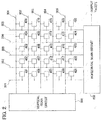
- Fig. 2 is a diagram schematically showing the configuration of the image pickup device 20 in Fig. 1 .
- a plurality of pixels (a plurality of detection elements) 401 to 425 are arranged in a row direction and a column direction like a matrix. Pixels of each row that are arrayed in the row direction (pixels 401, 402, 403, 404 and 405 in the case of the first row) are connected to a common drive wire (drive wire 301 in the case of the first row).
- Pixels of each column that are arrayed in the column direction are connected to a common signal wire (signal wire 201 in the case of the first column).
- the drive wires 301, 302, 303, 304 and 305 of the rows are successively driven (namely, supplied with a drive pulse) by a vertical scan circuit 300 as a vertical scan unit.
- signals i.e., pixel values or detection values
- the pixels of the row are successively outputted via the signal wires 201, 202, 203, 204 and 205 and a horizontal scan circuit 200 as a horizontal scan unit.
- the number of pixels of the image pickup device 20 is not limited to this example.
- the number of pixels of the image pickup device may be 240 rows by 320 columns, for example.
- the image capturing device 1 may include a lens unit as an imaging optical system that forms an image of the subject on the image pickup device 20.
- the lens unit includes, for example, a lens set including one lens or a plurality of lenses.
- the lens unit may have a function of allowing a light component in a predetermined wavelength range to pass through.
- Light radiating from the subject is condensed by the lens unit and forms an image on the plurality of detection elements, i.e., the plurality of pixels, of the image pickup device 20.
- Each detection element of the image pickup device 20 outputs a signal having a value corresponding to the intensity of incident light (i.e., pixel value) as the image signal Yin.
- the image pickup device 20 outputs a plurality of pixel values in the order of the raster scan as the image signal Yin.
- the delay unit 101 shown in Fig. 1 delays the pixel values Yin(i)[F] as the image signal Yin outputted from the image pickup device 20 by a delay time determined based on a line fluctuation noise correction process which will be described later.
- the pixel value fluctuation amount calculation unit 102 obtains the pixel value fluctuation amount d(i) of the i-th pixel from the pixel value Yin(i)[F] of the i-th pixel in the F-th frame as the image signal Yin outputted from the image pickup device 20 and the pixel value Yout(i)[F-1] of the same pixel in a frame one frame earlier (i.e., (F-1)-th frame) as a line fluctuation noise correction signal.
- the F-th frame in this case is defined as a reference frame.
- the pixel value fluctuation amount calculation unit 102 obtains the pixel value fluctuation amount d(i)[F] of the i-th pixel in the F-th frame by subtracting the pixel value Yout(i)[F-1] of the same i-th pixel in the (F-1)-th frame of the image signal Yout from the pixel value Yin(i)[F] of the i-th pixel in the F-th frame of the image signal Yin.
- the pixel value fluctuation amount calculation unit 102 calculates the pixel value fluctuation amount d(5)[10] regarding the fifth pixel Yin(5)[10] in the tenth frame by subtracting the fifth pixel Yout(5)[9] of the line fluctuation noise correction signal Yout as the image signal of the ninth frame (i.e., one frame earlier than the tenth frame) from the fifth pixel Yin(5)[10] of the tenth frame of the image signal Yin outputted from the image pickup device 20.
- the line fluctuation amount calculation unit 103 averages the pixel value fluctuation amounts d(i)[F] outputted from the pixel value fluctuation amount calculation unit 102 in the range of the partial line. Namely, the line fluctuation amount calculation unit 103 calculates the line fluctuation amount ave(i)[F] as the average value of the pixel values of the N pixels included in the range of the partial line.
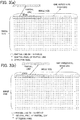
- Figs. 3(a) and 3(b) are diagrams showing an outline of a method of determining the range of the partial line by using a moving average method.
- the line fluctuation amount ave(i)[F] is calculated in the range of the partial line while successively shifting the range of the partial line (i.e., the section of the partial line) by one pixel each time as shown in Figs. 3(a) and 3(b) .
- Figs. 4(a) and 4(b) are diagrams showing an outline of a method of determining the range of the partial line by using a fixed partitioning method.
- the line fluctuation amount ave(i)[F] is calculated in the range of the partial line while successively shifting the range of the partial line (i.e., the section of the partial line) by the number of pixels included in the partial line each time as shown in Figs. 4(a) and 4(b) .
- the range of the partial line i.e., N as the number of pixels included in the partial line, is determined based on the width of the image size, that is, the number of pixels in one horizontal scan line. For example, when the number of pixels in one horizontal scan line is 320, N indicating the range of the partial line is 16 as 1/20 of the number of pixels in one horizontal scan line. However, the number N of pixels included in the partial line may also be determined as a number other than 16 (e.g., 32 as 1/10 of the number of pixels in one horizontal scan line, 64 as 1/5 of the number of pixels in one horizontal scan line, etc.). As above, the number of pixels included in the partial line can be determined in the range from 1/20 to 1/5 of the number of pixels in one horizontal scan line.
- the number N of pixels included in the partial line can also be determined at a different number smaller than the number of pixels in one horizontal scan line. It is also possible to increase the range of the partial line with the increase in the image size. Alternatively, it is also possible not to change the range of the partial line even with the increase in the image size. It is also possible to appropriately determine the number of pixels included in the range of the partial line based on the angle of view and the number of pixels of the image capturing device 1, the size of the subject in the scene captured by the image capturing device 1, the distance to the subject, or the like.
- the moving average method When the moving average method is used, unnaturalness corresponding to movement of the subject hardly appears in the line fluctuation amount ave(i). However, the number of calculations increases when the moving average method is used.
- the fixed partitioning method When the fixed partitioning method is used, a smoothing process is performed in the horizontal scan direction, by which unnaturalness at boundaries between adjacent partial lines can be made less noticeable.
- the fixed partitioning method When the fixed partitioning method is used, the number of calculations can be reduced.
- the circuit scale of the line fluctuation amount calculation unit 103 can be downsized compared to cases where the moving average method is used.
- range of N 32 pixels
- the variance value calculation unit 104 calculates the variance value var(i)[F] of the partial line from the pixel value fluctuation amounts d(i)[F] outputted from the pixel value fluctuation amount calculation unit 102 and the line fluctuation amount ave(i)[F] outputted from the line fluctuation amount calculation unit 103.
- the variance value calculation unit 104 can obtain the variance value var(i)[F] as the root mean square of the differences from the average value.
- the variance value calculation unit 104 may first calculate the root mean square s_ave(i)[F] of the pixel value fluctuation amounts d(i)[F] in regard to the range of the partial line and then obtain the variance value var(i)[F] by subtracting (ave(i)[F]) 2 as the square of the line fluctuation amount ave(i)[F] from the root mean square s_ave(i)[F].
- the screen variance value average calculation unit 105 calculates a screen variance value average AVE_VAR[F] of the F-th frame, as the average of the variance values of the partial lines in the whole screen, from the variance values var(i)[F] outputted from the variance value calculation unit 104.
- M represents the total number of pixels in one frame.
- M represents 320 pixels horizontally and 240 pixels vertically, M equals 320 ⁇ 240 pixels.
- the screen variance value average AVE_VAR[F] is an index indicating the random noise level in the screen of the F-th frame including also the movement component.
- the target reference variance value calculation unit 106 calculates a target reference variance value TVAR[F] by multiplying the variance value average AVE_VAR[F] of the screen outputted from the screen variance value average calculation unit 105 by a set value Rv that is used for adjusting threshold values (e.g., a first threshold value and a second threshold value shown in Fig. 5 which will be explained later) for discrimination between a moving object (i.e., dynamic object) and a stopped object (i.e., stationary object).
- the set value Rv is a value for adjusting the threshold values used for the discriminating between a moving object and a stationary object.
- the default value of the set value Rv is 1.0, for example.
- the set value Rv may be inputted from the outside, the set value Rv may also be previously stored in a storage unit in the image capturing device 1.
- the target reference variance value TVAR[F] outputted from the target reference variance value calculation unit 106 is calculated by using the following expression 5, for example:
- the movement adaptive weight determination unit 114 may also be configured without the target reference variance value calculation unit 106 so that the variance value average AVE_VAR[F] of the screen is supplied to the reference variance value calculation unit 107.
- TVAR F Rv ⁇ AVE _ VAR F
- the reference variance value calculation unit 107 calculates a reference variance value RVAR[F], indicating threshold values used for discriminating between a moving object and a stationary object in regard to each screen, namely, each frame, from the target reference variance value TVAR[F] outputted from the target reference variance value calculation unit 106.
- RVAR[F] is the reference variance value in the F-th frame.
- RVAR[F] represent the reference variance value in the F-th frame and RVAR[F-1] represent an already-acquired reference variance value in the (F-1)-th frame one frame earlier than the F-th frame
- RVAR F RVAR F ⁇ 1 ⁇ 1 ⁇ ⁇ + TVAR F ⁇ ⁇
- a ratio of the movement component increases i.e., a ratio of movement judgments in which the pixel value of a pixel is judged to include the movement component increases
- the ratio of the movement component decreases i.e., the ratio of movement judgments in which the pixel value of a pixel is judged to include the movement component decreases
- ⁇ represents an exponential smoothing coefficient.
- the default value of ⁇ is 0.25, for example. While ⁇ may be a value inputted from the outside, ⁇ may also be previously stored in the storage unit of the image capturing device 1.
- Fig. 5 is a diagram showing a graph of a movement adaptive weight property when a standard reference variance value is 384.
- the scaling factor calculation unit 108 calculates a scaling factor Rs from a ratio between the predetermined standard reference variance value and the reference variance value RVAR[F] outputted from the reference variance value calculation unit 107.
- the variance value index calculation unit 109 calculates a variance value index i_var(i)[F] by multiplying the variance value var(i)[F] calculated by the variance value calculation unit 104 by the scaling factor Rs[F] calculated by the scaling factor calculation unit 108.
- the variance value index i_var(i)[F] is an index used for the calculation of the movement adaptive weight w(i)[F] based on the standard movement adaptive weight property.
- the movement adaptive weight calculation unit 110 calculates a weight as a coefficient to be applied to each of a moving object and a stationary object, i.e., the movement adaptive weight w(i)[F], from the variance value index i_var(i)[F] outputted from the variance value index calculation unit 109.
- the variance value equals the amount of random noise in the image when only a stationary object exists and no moving object exists in the image, and the variance value equals "(random noise amount) + (movement amount)" when a moving object exists in the image.
- the movement adaptive weight calculation unit 110 controls the movement adaptive weight w(i)[F] by judging the movement amount based on the variance value.
- a variance value when the movement adaptive weight w(i)[F] equals 0.5 in a range 0.0 to 1.0 of the movement adaptive weight w(i)[F] is defined as the reference variance value of the threshold values used for discriminating between a moving object and a stationary object.
- the range of the movement adaptive weight w(i)[F] is 0.0 to 1.0, for example.
- the image signal is not corrected when the value of the movement adaptive weight w(i)[F] is 0.0, and the image signal is corrected by directly using the line fluctuation amount when the value of the movement adaptive weight w(i)[F] is 1.0.
- Fig. 5 shows a graph of an example of the property of the movement adaptive weight w(i) [F].
- the graph of the movement adaptive weight w(i)[F] may also be expressed by a quartic equation.
- Wmin represent a minimum weight as the minimum value of the movement adaptive weight w(i)[F]
- Wmin saturation limitation
- the default value of the minimum weight Wmin is 0.0, for example, the default value may also be set at a value larger than 0.0.
- the range of the movement adaptive weight may also be set as 0 to 100 instead of 0.0 to 1.0. However, since the value of the movement adaptive weight w(i) is used by the correction amount calculation unit 111, it is desirable to perform normalization so as to make it possible to multiply the image signal Yin[F] directly by the movement adaptive weight w(i).
- the correction amount calculation unit 111 calculates the line fluctuation noise correction amount c_lfn(i)[F] by multiplying the movement adaptive weight w(i)[F] outputted from the movement adaptive weight calculation unit 110 by the line fluctuation amount ave(i)[F] outputted from the line fluctuation amount calculation unit 103.
- the movement adaptive weight When the movement adaptive weight is 0.0, no correction is made, and thus the line fluctuation noise cannot be reduced even though inappropriate correction due to the movement component in the image signal can be prevented.
- the movement adaptive weight w(i) when the movement adaptive weight w(i) is 1.0, the line fluctuation amount ave(i) is directly used for the correction of the image signal, and thus the line fluctuation noise is appropriately corrected when the subject is a stationary object.
- inappropriate correction is made since line fluctuation due to the movement component in the image signal (i.e., line fluctuation other than the line fluctuation noise) is reduced.
- the line fluctuation noise correction unit 112 outputs a digital signal after the correction of the line fluctuation noise, that is, the image signal Yout(i)[F] after the correction, by subtracting the line fluctuation noise correction amount c_lfn(i)[F] outputted from the correction amount calculation unit 111 from the image signal outputted from the delay unit 101.
- the line fluctuation noise correction amount c_lfn(i)[F] it is desirable to subtract a line fluctuation noise correction amount Rc ⁇ c_lfn(i)[F] obtained by multiplying the line fluctuation noise correction amount c_lfn(i)[F] by a correction ratio Rc.
- the correction ratio Rc is set at 1.0 and the correction is made 100%, offset displacement between vertical lines (horizontal stripe pattern) in an image as the reference keeps on remaining without disappearing.
- Yout(i)[F] represent the image signal after the line fluctuation noise correction
- Rc The default value of Rc is 0.875, for example. While Rc may be inputted from the outside, Rc may also be previously stored in the storage unit of the image capturing device 1.
- the frame delay unit 113 performs one-frame delay in consideration of a processing delay amount so that the difference calculation can be done between the pixel value Yout(i)[F] of the image signal outputted from the line fluctuation noise correction unit 112 and a pixel at the same pixel position in the frame one frame earlier.
- the line fluctuation noise can be suppressed appropriately even when a moving object exists in the subject.
- the amount of the random noise is estimated by using the screen variance value average AVE_VAR[F] of one frame. Accordingly, estimation accuracy of the movement amount in one frame can be increased and an appropriate correction amount c_lfn(i)[F] according to the movement amount can be calculated.
- the movement adaptive weight property graph (shown in Fig. 6 ) can be modified according to the screen variance value average to a more appropriate graph suitable for the scene of the input image.
- Fig. 6 is a block diagram schematically showing a configuration of an image capturing device 2 according to a second embodiment of the present invention.
- each component identical or corresponding to a component shown in Fig. 1 is assigned the same reference character as in Fig. 1 .
- Fig. 6 As shown in Fig.
- the image capturing device 2 includes a shutter 40 that switches its state to an open state of allowing the light from the subject to pass through or a closed state of interrupting the light from the subject, a fixed pattern noise calculation unit (FPN calculation unit) 50 that calculates a fixed pattern noise (FPN) component occurring in the image pickup device 20, a control unit 60 for controlling the operation of the shutter 40, and a subtraction unit 30 that subtracts the FPN component from the image signal Yin(i)[F], in addition to the image pickup device 20, the lens unit 21 and the line fluctuation noise reduction unit 10.
- FPN calculation unit fixed pattern noise calculation unit 50 that calculates a fixed pattern noise (FPN) component occurring in the image pickup device 20
- control unit 60 for controlling the operation of the shutter 40
- subtraction unit 30 that subtracts the FPN component from the image signal Yin(i)[F], in addition to the image pickup device 20, the lens unit 21 and the line fluctuation noise reduction unit 10.
- the shutter 40 is arranged in front (i.e., on the subject's side) of the lens unit 21 and is used as a light transmission/interruption unit capable of switching between the open state of permitting light as a wavelength range component detectable by the image pickup device 20 (e.g., infrared rays, ultraviolet rays, visible rays, etc.) to enter the image pickup device 20 and the closed state of not permitting the light to enter.
- the shutter 40 may also be arranged between the lens unit 21 and the image pickup device 20. In this case, processing in consideration of the influence of the lens unit 21 is desired to be performed additionally in a correction process for removing the FPN component.
- the image pickup device 20 When the shutter 40 is in the open state, light radiating from the subject is condensed by the lens unit 21 and forms an image on the plurality of detection elements of the image pickup device 20.
- the image pickup device 20 outputs pixel values, at levels corresponding to the intensity of the light entering the plurality of detection elements, successively (e.g., in the order of the raster scan) as the image signal.
- the image signal outputted from the image pickup device 20 when the shutter 40 is in the open state includes not only a signal component as a component corresponding to the light radiating from the subject but also the FPN component and a variation component caused by variations in the peak value of the vertical drive pulse applied to the drive wires of the image pickup device 20.
- the shutter 40 When the shutter 40 is in the closed state, the entry of the light into the image pickup device 20 is interrupted. In this closed state, the image signal outputted from the image pickup device 20 does not include the signal component and includes only the FPN component and the component caused by the variations in the peak value of the vertical drive pulse.
- the control unit 60 is, for example, a control circuit including a timing generation unit 601 and a shutter control unit 602.
- the FPN calculation unit 50 is, for example, a processing circuit including an addition unit 501, a frame memory 502 as a storage unit, a frame memory control unit 503, and a division unit 504.
- the timing generation unit 601 outputs an operation mode signal ST as a timing signal indicating whether the image capturing device 2 is in an update mode for updating a correction value based on a noise component such as the FPN component or in a normal image capturing mode for capturing images of a subject.
- the shutter control unit 602 performs control for switching the shutter 40 to the open state (at times of the normal image capturing mode) or the closed state (at times of the update mode) according to the operation mode signal ST outputted from the timing generation unit 601.
- the image capturing device 2 sets its operation mode to the update mode when the power of the image capturing device 2 is turned on and when the user commanded the update mode through an operation input unit (not shown). For example, when the timing generation unit 601 sets the operation mode signal ST at a low level that is lower than a normal level, the shutter control unit 602 sets the shutter 40 in the closed state and the frame memory control unit 503 executes control for performing the writing to the frame memory 502, that is, for updating the value of the FPN component stored in the frame memory 502.
- the FPN calculation unit 50 calculates the FPN component included in the image signal outputted from the image pickup device 20, holds the result of the calculation, and outputs a signal corresponding to the held FPN component.
- the shutter 40 When the operation mode signal ST indicates the update mode for commanding the update of the FPN component stored in the frame memory 502, the shutter 40 is in the closed state and the image signals Yout(i)[F] outputted from the line fluctuation noise correction unit 112 in the line fluctuation noise reduction unit 10 are added up by the addition unit 501 for a predetermined frame number of frames (e.g., 64 frames) and the totalized image signal obtained by the addition is stored in the frame memory 502.
- the division unit 504 reads out the totalized image signal from the frame memory 502, divides each pixel value in the totalized image signal by the predetermined frame number, and supplies the subtraction unit 30 with the result of the division as the FPN component.
- the shutter 40 When the operation mode signal ST indicates the normal image capturing mode, the shutter 40 is in the open state and the division unit 504 reads out the totalized image signal from the frame memory 502, divides each pixel value in the totalized image signal by the predetermined frame number, and supplies the subtraction unit 30 with the result of the division as the FPN component.
- the number of frames added up may also be determined arbitrarily by the user based on performance or amplitude of the random noise.
- the addition unit 501 adds the signal read out from the frame memory 502 and the image signal Yout(i)[F] outputted from the line fluctuation noise correction unit 112 together and stores the result of the addition in the frame memory 502.
- the frame memory control unit 503 repeats the operation of storing the addition result outputted from the addition unit 501 in the frame memory 502 for the predetermined frame number, and stops the storing of the addition result in the frame memory 502 when the result of the repetition of the addition for the predetermined frame number is stored in the frame memory 502.
- the division unit 504 divides each pixel value in the image signal outputted from the frame memory 502 by the same value as the number of frames added up.
- the division unit 504 provides the subtraction unit 30 with the result of the division as an input signal.
- the subtraction unit 30 is used for the difference calculation of calculating the difference from the image signal in the next frame.
- the following advantage is obtained in addition to the advantages obtained with the image capturing device 1 according to the embodiment.
- the line fluctuation noise can be suppressed appropriately since the image signal from which the FPN component has been removed is inputted to the line fluctuation noise reduction unit 10.
- the removal of the FPN is performed first and thereafter the removal of the line fluctuation noise is performed.
- the pixel values obtained by capturing an image of the subject as the detection target, the temperature at each position on the detection target, and the distance to each position on the detection target are examples of a physical quantity of the detection target.
- Fig. 7 is a block diagram schematically showing a configuration of a detection device 1a and a line fluctuation noise reduction unit 10a according to a third embodiment of the present invention.
- the detection device 1a according to the third embodiment includes a detection unit 20a and the line fluctuation noise reduction device 10a.
- the detection unit 20a includes a plurality of detection elements arranged two-dimensionally similarly to the image pickup device 20 in the first and second embodiments.
- the plurality of detection elements detects a physical quantity such as the temperature of the detection target or the distance to the detection target.
- the detection unit 20a outputs a plurality of detection values corresponding to the plurality of detection elements as a detection signal.
- the line fluctuation noise reduction device 10a performs a correction process similar to the correction process of the line fluctuation noise reduction unit 10 in the first or second embodiment.
- the line fluctuation noise reduction device 10a includes a delay unit 101a, a detection value fluctuation amount calculation unit 102a, a line fluctuation amount calculation unit 103a, a variance value calculation unit 104a, a variance value average calculation unit 105a, a target reference variance value calculation unit 106a, a reference variance value calculation unit 107a, a scaling factor calculation unit 108a, a variance value index calculation unit 109a, a movement adaptive weight calculation unit 110a, a correction amount calculation unit 111a, a line fluctuation noise correction unit 112a and a frame delay unit 113a.
- the variance value average calculation unit 105a, the target reference variance value calculation unit 106a, the reference variance value calculation unit 107a, the scaling factor calculation unit 108a, the variance value index calculation unit 109a and the movement adaptive weight calculation unit 110a constitute a movement adaptive weight determination unit 114a.
- the line fluctuation noise reduction device 10a As described above, by using the line fluctuation noise reduction device 10a according to the third embodiment, the line fluctuation noise can be suppressed appropriately even when a moving object exists in the detection target.
- the amount of the random noise is estimated by using the variance value average AVE_VAR[F] of one frame. Accordingly, the estimation accuracy of the movement amount in one frame can be increased and an appropriate correction amount c_lfn(i)[F] according to the movement amount can be calculated.
- the line fluctuation noise reduction device 10a according to the third embodiment is the same as the line fluctuation noise reduction unit 10 according to the first or second embodiment.
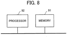
- Fig. 8 is a diagram schematically showing an example of a hardware configuration of the line fluctuation noise reduction unit in the first or second embodiment or the line fluctuation noise reduction device according to the third embodiment.
- the line fluctuation noise reduction unit 10 shown in Fig. 1 or the line fluctuation noise reduction device 10a shown in Fig. 7 can be implemented by using a memory 91 as a storage device storing a program as software and a processor 92 as an information processing unit executing the program stored in the memory 91 (e.g., by a computer). It is also possible to implement part of the line fluctuation noise reduction unit 10 shown in Fig. 1 or the line fluctuation noise reduction device 10a shown in Fig. 7 with the memory 91 shown in Fig. 8 and the processor 92 executing a program.
Landscapes
- Engineering & Computer Science (AREA)
- Multimedia (AREA)
- Signal Processing (AREA)
- Physics & Mathematics (AREA)
- General Physics & Mathematics (AREA)
- Theoretical Computer Science (AREA)
- Studio Devices (AREA)
- Picture Signal Circuits (AREA)
- Image Processing (AREA)
Abstract
Description
- The present invention relates to an image capturing device and a line fluctuation noise reduction device.
- An image pickup device (e.g., image sensor) captures an image of a subject by using a plurality of detection elements arranged two-dimensionally and thereby successively outputs pixel values of a plurality of pixels corresponding to the plurality of detection elements as an image signal. This image signal can contain line fluctuation noise as level fluctuation in the pixel values of each horizontal scan line due to a noise component in each horizontal scan line (see
Patent Reference 1, for example). - The line fluctuation noise causes flicker in the image and lowers visibility of the image. As a method for suppressing the line fluctuation noise, there is a method of correcting the image signal so that the average value of the pixel values in each horizontal scan line in the image signal becomes constant. In this method, the difference between the average value of the pixel values of all pixels in one horizontal scan line and the average value of the pixel values of all pixels in the same horizontal scan line in a frame one frame earlier, or a line fluctuation value as the average value of the difference between the pixel value of each pixel in one horizontal scan line and the pixel value of the same pixel in the same horizontal scan line in a frame one frame earlier, is used as a correction value.
- Patent Reference 1: Japanese Patent No.
4749397 - However, the line fluctuation value calculated when the subject includes a moving part contains a movement component as a fluctuation component not due to the noise component in each horizontal scan line, namely, as a fluctuation component due to the moving part. Accordingly, there is a problem in that the line fluctuation noise cannot be reduced appropriately if the image signal is corrected by using the line fluctuation value as the correction value.
- An object of the present invention, which has been made to resolve the above-described problem with the conventional technology, is to provide an image capturing device capable of appropriately reducing the line fluctuation noise even when a moving part is included in the subject and a line fluctuation noise reduction device capable of appropriately reducing the line fluctuation noise even when a moving part is included in a detection target.
- An image capturing device according to an aspect of the present invention includes: an image capturing unit that includes a plurality of detection elements arranged two-dimensionally in a horizontal scan direction and a vertical direction, captures an image of a subject, and thereby outputs pixel values of a plurality of pixels corresponding to the plurality of detection elements; a pixel value fluctuation amount calculation unit that calculates a pixel value fluctuation amount as a fluctuation amount of each of the pixel values in a time direction; a line fluctuation amount calculation unit that calculates a line fluctuation amount as an average value of N pixel value fluctuation amounts of N pixels in a partial line where N is an integer smaller than a total number of pixels in a horizontal scan line and the partial line is a range of N consecutive pixels in the horizontal scan line; a variance value calculation unit that calculates a variance value of the N pixel value fluctuation amounts from the N pixel value fluctuation amounts and the line fluctuation amount; a movement adaptive weight determination unit that calculates a movement adaptive weight based on the variance value; a correction amount calculation unit that calculates a line fluctuation noise correction amount, corresponding to each of the pixel values outputted from the image capturing unit, from the line fluctuation amount and the movement adaptive weight; and a line fluctuation noise correction unit that corrects each of the pixel values outputted from the image capturing unit by using the line fluctuation noise correction amount and thereby generates an image signal after the correction.
- A line fluctuation noise reduction device according to another aspect of the present invention is a device that receives a detection signal outputted from a detection unit including a plurality of detection elements arranged two-dimensionally in a horizontal scan direction and a vertical direction, detecting a physical quantity of a detection target, and thereby outputting detection values of a plurality of detection points corresponding to the plurality of detection elements, including: a detection value fluctuation amount calculation unit that calculates a detection value fluctuation amount as a fluctuation amount of each of the detection values in a time direction; a line fluctuation amount calculation unit that calculates a line fluctuation amount as an average value of N detection value fluctuation amounts of N detection points in a partial line where N is an integer smaller than a total number of detection points in a horizontal scan line and the partial line is a range of N consecutive detection points in the horizontal scan line; a variance value calculation unit that calculates a variance value of the N detection value fluctuation amounts from the N detection value fluctuation amounts and the line fluctuation amount; a movement adaptive weight determination unit that calculates a movement adaptive weight based on the variance value; a correction amount calculation unit that calculates a line fluctuation noise correction amount, corresponding to each of the detection values outputted from the detection unit, from the line fluctuation amount and the movement adaptive weight; and a line fluctuation noise correction unit that corrects each of the detection values outputted from the detection unit by using the line fluctuation noise correction amount and thereby generates the detection signal after the correction.
- With the image capturing device according to the present invention, even when a moving part is included in the subject, the line fluctuation noise can be reduced appropriately while inhibiting influence on the movement component of the image signal.
- With the line fluctuation noise reduction device according to the present invention, even when a moving part is included in the detection target, the line fluctuation noise can be reduced appropriately while inhibiting influence on the movement component of the detection signal.
-
-
Fig. 1 is a block diagram schematically showing a configuration of an image capturing device according to a first embodiment of the present invention. -
Fig. 2 is a diagram schematically showing a configuration example of the image pickup device of the image capturing device shown inFig. 1 . -
Figs. 3(a) and 3(b) are diagrams showing an outline of a method of determining a range of a partial line by using a moving average method. -
Figs. 4(a) and 4(b) are diagrams showing an outline of a method of determining the range of the partial line by using a fixed partitioning method. -
Fig. 5 is a diagram showing a graph of a movement adaptive weight property when a standard reference variance value is 384. -
Fig. 6 is a block diagram schematically showing a configuration of an image capturing device according to a second embodiment of the present invention. -
Fig. 7 is a block diagram schematically showing a configuration of a line fluctuation noise reduction device according to a third embodiment of the present invention. -
Fig. 8 is a diagram schematically showing a hardware configuration of a modification of the first to third embodiments. - Image capturing devices and line fluctuation noise reduction devices according to embodiments of the present invention will be described below with reference to the accompanying drawings. The following embodiments are just examples and a variety of modifications are possible within the scope of the present invention.
-
Fig. 1 is a block diagram schematically showing a configuration of an image capturingdevice 1 according to a first embodiment of the present invention. As shown inFig. 1 , the image capturingdevice 1 according to the first embodiment includes animage pickup device 20 as an image capturing unit and a line fluctuationnoise reduction unit 10 as a line fluctuation noise reduction device. - The
image pickup device 20 includes a plurality of detection elements arranged two-dimensionally in a horizontal scan direction and a vertical direction, captures an image of a subject by using the plurality of detection elements, and thereby outputs pixel values of a plurality of pixels corresponding to the plurality of detection elements as an image signal. The image signal is represented as Yin. Each pixel value forming the image signal Yin is represented as Yin(i). Among the pixel values forming the image signal Yin, the pixel value of the i-th pixel in a frame that is the F-th (hereinafter referred to also as an "F-th frame") is represented as Yin(i) [F]. In the following description, i in round brackets () is a positive integer indicating the number of a pixel in a certain frame. Further, F in square brackets is a positive integer indicating a frame number. - The line fluctuation
noise reduction unit 10 is a signal processing circuit, for example. As shown inFig. 1 , the line fluctuationnoise reduction unit 10 includes adelay unit 101, a pixel value fluctuationamount calculation unit 102, a line fluctuationamount calculation unit 103, a variancevalue calculation unit 104, a screen variance valueaverage calculation unit 105, a target reference variancevalue calculation unit 106, a reference variance value calculation unit 107, a scalingfactor calculation unit 108, a variance valueindex calculation unit 109, a movement adaptiveweight calculation unit 110, a correctionamount calculation unit 111, a line fluctuation noise correction unit 112 and aframe delay unit 113. The screen variance valueaverage calculation unit 105, the target reference variancevalue calculation unit 106, the reference variance value calculation unit 107, the scalingfactor calculation unit 108, the variance valueindex calculation unit 109 and the movement adaptiveweight calculation unit 110 constitute a movement adaptiveweight determination unit 114. - The pixel value fluctuation
amount calculation unit 102 calculates a pixel value fluctuation amount d(i) as a fluctuation amount of each of the pixel values in a time direction. The pixel value fluctuation amount when the pixel value Yin(i)[F] of the i-th pixel in the F-th frame is inputted, i.e., the pixel value fluctuation amount corresponding to the pixel value of the i-th pixel in the F-th frame, is represented as d(i)[F]. - Assuming that N is an integer smaller than a total pixel number L as the total number of pixels in a horizontal scan line and a partial line is a range of N consecutive pixels in the horizontal scan line, the line fluctuation
amount calculation unit 103 calculates a line fluctuation amount ave(i) as the average value of N pixel value fluctuation amounts of the N pixels in the partial line. The line fluctuation amount corresponding to the pixel value of the i-th pixel in the F-th frame is represented as ave(i)[F]. Concrete examples of the partial line will be described later. - The variance
value calculation unit 104 calculates a variance value var(i) of the N pixel value fluctuation amounts from the N pixel value fluctuation amounts of the N pixels in the partial line and the line fluctuation amount. The variance value var(i) of the N pixel value fluctuation amounts calculated from the N pixel value fluctuation amounts of the N pixels in the F-th frame and the line fluctuation amount ave(i)[F] corresponding to the pixel value of the i-th pixel in the F-th frame is represented as var(i)[F]. - The movement adaptive
weight determination unit 114 calculates a movement adaptive weight w(i) based on the variance value var(i). The movement adaptive weight w(i) corresponding to the pixel value of the i-th pixel in the F-th frame is represented as w(i) [F]. In the first embodiment, the movement adaptive weight w(i)[F] takes on a small value when there is a lot of moving parts included in the subject, and the movement adaptive weight w(i)[F] takes on a large value when there is few moving parts included in the subject. - The correction
amount calculation unit 111 calculates a line fluctuation noise correction amount c_lfn(i), corresponding to each of the pixel values outputted from theimage capturing unit 20, from the line fluctuation amount ave(i) and the movement adaptive weight w(i). The line fluctuation noise correction amount corresponding to the pixel value of the i-th pixel in the F-th frame is represented as c_lfn(i) [F]. In the first embodiment, the line fluctuation noise correction amount c_lfn(i)[F] takes on a small value when there is a lot of moving parts included in the subject, and the line fluctuation noise correction amount c_lfn(i)[F] takes on a large value when there is few moving parts included in the subject. - The line fluctuation noise correction unit 112 corrects each of the pixel values Yin(i) outputted from the
image capturing unit 20 by using the line fluctuation noise correction amount c_lfn(i) and thereby generates an image signal Yout(i) after the correction. The pixel value of the image signal after the correction corresponding to the pixel value of the i-th pixel in the F-th frame is represented as Yout(i)[F]. - With the image capturing
device 1 according to the first embodiment, the line fluctuation noise correction amount c_lfn(i)[F] takes on a small value when there is a lot of moving parts included in the subject, and the line fluctuation noise correction amount c_lfn(i)[F] takes on a large value when there is few moving parts included in the subject. Accordingly, when there is a lot of moving parts included in the subject, the movement component in the image signal is unlikely to be reduced. Further, when there is few moving parts included in the subject, the line fluctuation noise is reduced appropriately. - The
image pickup device 20 includes a plurality of detection elements having sensitivity in a predetermined wavelength range. The plurality of detection elements is arranged in multiple rows and columns on a two-dimensional plane. Theimage pickup device 20 performs the image capturing every predetermined frame period. The predetermined wavelength range is, for example, a wavelength range from 8 µm to 14 µm, namely, the infrared range. However, the predetermined wavelength range may also be a different wavelength range. The predetermined wavelength range can also be a wavelength range from 200 nm to 400 nm, namely, the ultraviolet range. In the first embodiment, a case where the predetermined wavelength range is the infrared range will be described. -
Fig. 2 is a diagram schematically showing the configuration of theimage pickup device 20 inFig. 1 . As shown inFig. 2 , in theimage pickup device 20, a plurality of pixels (a plurality of detection elements) 401 to 425 are arranged in a row direction and a column direction like a matrix. Pixels of each row that are arrayed in the row direction (pixels drive wire 301 in the case of the first row). Pixels of each column that are arrayed in the column direction (pixels signal wire 201 in the case of the first column). Thedrive wires vertical scan circuit 300 as a vertical scan unit. While thedrive wire pixels signal wires horizontal scan circuit 200 as a horizontal scan unit. Incidentally, while pixels of five rows and five columns are shown inFig. 2 , the number of pixels of theimage pickup device 20 is not limited to this example. The number of pixels of the image pickup device may be 240 rows by 320 columns, for example. - The
image capturing device 1 may include a lens unit as an imaging optical system that forms an image of the subject on theimage pickup device 20. The lens unit includes, for example, a lens set including one lens or a plurality of lenses. The lens unit may have a function of allowing a light component in a predetermined wavelength range to pass through. Light radiating from the subject is condensed by the lens unit and forms an image on the plurality of detection elements, i.e., the plurality of pixels, of theimage pickup device 20. Each detection element of theimage pickup device 20 outputs a signal having a value corresponding to the intensity of incident light (i.e., pixel value) as the image signal Yin. In the first embodiment, theimage pickup device 20 outputs a plurality of pixel values in the order of the raster scan as the image signal Yin. - The
delay unit 101 shown inFig. 1 delays the pixel values Yin(i)[F] as the image signal Yin outputted from theimage pickup device 20 by a delay time determined based on a line fluctuation noise correction process which will be described later. - The pixel value fluctuation
amount calculation unit 102 obtains the pixel value fluctuation amount d(i) of the i-th pixel from the pixel value Yin(i)[F] of the i-th pixel in the F-th frame as the image signal Yin outputted from theimage pickup device 20 and the pixel value Yout(i)[F-1] of the same pixel in a frame one frame earlier (i.e., (F-1)-th frame) as a line fluctuation noise correction signal. The F-th frame in this case is defined as a reference frame. Specifically, the pixel value fluctuationamount calculation unit 102 obtains the pixel value fluctuation amount d(i)[F] of the i-th pixel in the F-th frame by subtracting the pixel value Yout(i)[F-1] of the same i-th pixel in the (F-1)-th frame of the image signal Yout from the pixel value Yin(i)[F] of the i-th pixel in the F-th frame of the image signal Yin. This pixel value fluctuation amount d(i)[F] is calculated by using the followingexpression 1, for example:
- For example, the pixel value fluctuation
amount calculation unit 102 calculates the pixel value fluctuation amount d(5)[10] regarding the fifth pixel Yin(5)[10] in the tenth frame by subtracting the fifth pixel Yout(5)[9] of the line fluctuation noise correction signal Yout as the image signal of the ninth frame (i.e., one frame earlier than the tenth frame) from the fifth pixel Yin(5)[10] of the tenth frame of the image signal Yin outputted from theimage pickup device 20. - The line fluctuation
amount calculation unit 103 averages the pixel value fluctuation amounts d(i)[F] outputted from the pixel value fluctuationamount calculation unit 102 in the range of the partial line. Namely, the line fluctuationamount calculation unit 103 calculates the line fluctuation amount ave(i)[F] as the average value of the pixel values of the N pixels included in the range of the partial line. -
Figs. 3(a) and 3(b) are diagrams showing an outline of a method of determining the range of the partial line by using a moving average method. In the moving average method, the line fluctuation amount ave(i)[F] is calculated in the range of the partial line while successively shifting the range of the partial line (i.e., the section of the partial line) by one pixel each time as shown inFigs. 3(a) and 3(b) . -
Figs. 4(a) and 4(b) are diagrams showing an outline of a method of determining the range of the partial line by using a fixed partitioning method. In the fixed partitioning method, the line fluctuation amount ave(i)[F] is calculated in the range of the partial line while successively shifting the range of the partial line (i.e., the section of the partial line) by the number of pixels included in the partial line each time as shown inFigs. 4(a) and 4(b) . - The range of the partial line, i.e., N as the number of pixels included in the partial line, is determined based on the width of the image size, that is, the number of pixels in one horizontal scan line. For example, when the number of pixels in one horizontal scan line is 320, N indicating the range of the partial line is 16 as 1/20 of the number of pixels in one horizontal scan line. However, the number N of pixels included in the partial line may also be determined as a number other than 16 (e.g., 32 as 1/10 of the number of pixels in one horizontal scan line, 64 as 1/5 of the number of pixels in one horizontal scan line, etc.). As above, the number of pixels included in the partial line can be determined in the range from 1/20 to 1/5 of the number of pixels in one horizontal scan line. However, the number N of pixels included in the partial line can also be determined at a different number smaller than the number of pixels in one horizontal scan line. It is also possible to increase the range of the partial line with the increase in the image size. Alternatively, it is also possible not to change the range of the partial line even with the increase in the image size. It is also possible to appropriately determine the number of pixels included in the range of the partial line based on the angle of view and the number of pixels of the
image capturing device 1, the size of the subject in the scene captured by theimage capturing device 1, the distance to the subject, or the like. - When the moving average method is used, unnaturalness corresponding to movement of the subject hardly appears in the line fluctuation amount ave(i). However, the number of calculations increases when the moving average method is used. When the fixed partitioning method is used, a smoothing process is performed in the horizontal scan direction, by which unnaturalness at boundaries between adjacent partial lines can be made less noticeable. When the fixed partitioning method is used, the number of calculations can be reduced. When the fixed partitioning method is used, the circuit scale of the line fluctuation
amount calculation unit 103 can be downsized compared to cases where the moving average method is used. - The line fluctuation
amount calculation unit 103 may change the range of the partial line depending on the inputted image signal. For example, it is possible to set the number of pixels included in the range of the partial line at a small value (e.g., N = 16 pixels) when there is a lot of moving parts in the inputted image, and set the number of pixels included in the range of the partial line at a large value (e.g., range of N = 32 pixels) when there is a lot of moving parts in the inputted image. The line fluctuation amount ave(i)[F] as the average value of the pixel values of the N pixels included in the range of the partial line is calculated by using the followingexpression 2, for example:
- The variance
value calculation unit 104 calculates the variance value var(i)[F] of the partial line from the pixel value fluctuation amounts d(i)[F] outputted from the pixel value fluctuationamount calculation unit 102 and the line fluctuation amount ave(i)[F] outputted from the line fluctuationamount calculation unit 103. The variancevalue calculation unit 104 can obtain the variance value var(i)[F] as the root mean square of the differences from the average value. It is also possible for the variancevalue calculation unit 104 to first calculate the root mean square s_ave(i)[F] of the pixel value fluctuation amounts d(i)[F] in regard to the range of the partial line and then obtain the variance value var(i)[F] by subtracting (ave(i)[F])2 as the square of the line fluctuation amount ave(i)[F] from the root mean square s_ave(i)[F]. The variance value var(i)[F] outputted from the variancevalue calculation unit 104 is calculated by using the following expression 3, for example:
- The screen variance value
average calculation unit 105 calculates a screen variance value average AVE_VAR[F] of the F-th frame, as the average of the variance values of the partial lines in the whole screen, from the variance values var(i)[F] outputted from the variancevalue calculation unit 104. The screen variance value average AVE_VAR[F] of the F-th frame outputted from the screen variance valueaverage calculation unit 105 is calculated by using the following expression 4, for example:
- In the expression 4, M represents the total number of pixels in one frame. When one frame has 320 pixels horizontally and 240 pixels vertically, M equals 320 × 240 pixels. The screen variance value average AVE_VAR[F] is an index indicating the random noise level in the screen of the F-th frame including also the movement component.
- The target reference variance
value calculation unit 106 calculates a target reference variance value TVAR[F] by multiplying the variance value average AVE_VAR[F] of the screen outputted from the screen variance valueaverage calculation unit 105 by a set value Rv that is used for adjusting threshold values (e.g., a first threshold value and a second threshold value shown inFig. 5 which will be explained later) for discrimination between a moving object (i.e., dynamic object) and a stopped object (i.e., stationary object). Namely, the set value Rv is a value for adjusting the threshold values used for the discriminating between a moving object and a stationary object. The default value of the set value Rv is 1.0, for example. While the set value Rv may be inputted from the outside, the set value Rv may also be previously stored in a storage unit in theimage capturing device 1. Letting TVAR[F] represent the target reference variance value in the F-th frame, the target reference variance value TVAR[F] outputted from the target reference variancevalue calculation unit 106 is calculated by using the following expression 5, for example: Incidentally, in cases where Rv = 1, the movement adaptiveweight determination unit 114 may also be configured without the target reference variancevalue calculation unit 106 so that the variance value average AVE_VAR[F] of the screen is supplied to the reference variance value calculation unit 107.
- The reference variance value calculation unit 107 calculates a reference variance value RVAR[F], indicating threshold values used for discriminating between a moving object and a stationary object in regard to each screen, namely, each frame, from the target reference variance value TVAR[F] outputted from the target reference variance
value calculation unit 106. RVAR[F] is the reference variance value in the F-th frame. By performing exponential smoothing on the reference variance value in the time direction, major fluctuations in the time direction can be restrained. Letting RVAR[F] represent the reference variance value in the F-th frame and RVAR[F-1] represent an already-acquired reference variance value in the (F-1)-th frame one frame earlier than the F-th frame, the reference variance value RVAR[F] outputted from the reference variance value calculation unit 107 is calculated by using the following expression 6, for example:
- A ratio of the movement component increases (i.e., a ratio of movement judgments in which the pixel value of a pixel is judged to include the movement component increases) with the decrease in RVAR[F], and the ratio of the movement component decreases (i.e., the ratio of movement judgments in which the pixel value of a pixel is judged to include the movement component decreases) with the increase in RVAR[F]. Here, α represents an exponential smoothing coefficient. The default value of α is 0.25, for example. While α may be a value inputted from the outside, α may also be previously stored in the storage unit of the
image capturing device 1. -
Fig. 5 is a diagram showing a graph of a movement adaptive weight property when a standard reference variance value is 384. In order to use the standard movement adaptive weight property shown inFig. 5 , the scalingfactor calculation unit 108 calculates a scaling factor Rs from a ratio between the predetermined standard reference variance value and the reference variance value RVAR[F] outputted from the reference variance value calculation unit 107. The scaling factor Rs[F] in the F-th frame outputted from the scalingfactor calculation unit 108 is calculated by using the following expression 7, for example:
- The variance value
index calculation unit 109 calculates a variance value index i_var(i)[F] by multiplying the variance value var(i)[F] calculated by the variancevalue calculation unit 104 by the scaling factor Rs[F] calculated by the scalingfactor calculation unit 108. The variance value index i_var(i)[F] is an index used for the calculation of the movement adaptive weight w(i)[F] based on the standard movement adaptive weight property. The variance valueindex calculation unit 109 calculates the variance value index i_var(i)[F] in the F-th frame by using the following expression 8, for example:
- The movement adaptive
weight calculation unit 110 calculates a weight as a coefficient to be applied to each of a moving object and a stationary object, i.e., the movement adaptive weight w(i)[F], from the variance value index i_var(i)[F] outputted from the variance valueindex calculation unit 109. The variance value equals the amount of random noise in the image when only a stationary object exists and no moving object exists in the image, and the variance value equals "(random noise amount) + (movement amount)" when a moving object exists in the image. The movement adaptiveweight calculation unit 110 controls the movement adaptive weight w(i)[F] by judging the movement amount based on the variance value. A variance value when the movement adaptive weight w(i)[F] equals 0.5 in a range 0.0 to 1.0 of the movement adaptive weight w(i)[F] is defined as the reference variance value of the threshold values used for discriminating between a moving object and a stationary object. - The range of the movement adaptive weight w(i)[F] is 0.0 to 1.0, for example. The image signal is not corrected when the value of the movement adaptive weight w(i)[F] is 0.0, and the image signal is corrected by directly using the line fluctuation amount when the value of the movement adaptive weight w(i)[F] is 1.0.
- When the range of the movement adaptive weight w(i)[F] is between 0.0 and 1.0 (i.e., greater than 0.0 and less than 1.0), the movement adaptive weight w(i)[F] is changed linearly.
Fig. 5 shows a graph of an example of the property of the movement adaptive weight w(i) [F]. The graph of the movement adaptive weight w(i)[F] may also be expressed by a quartic equation. The movement adaptive weight w(i) outputted from the movement adaptiveweight calculation unit 110 is calculated by using the following expression 9, for example:
- Here, letting Wmin represent a minimum weight as the minimum value of the movement adaptive weight w(i)[F], it is possible to set saturation limitation with the minimum weight Wmin as w(i)[F] = Wmin. While the default value of the minimum weight Wmin is 0.0, for example, the default value may also be set at a value larger than 0.0.
- The range of the movement adaptive weight may also be set as 0 to 100 instead of 0.0 to 1.0. However, since the value of the movement adaptive weight w(i) is used by the correction
amount calculation unit 111, it is desirable to perform normalization so as to make it possible to multiply the image signal Yin[F] directly by the movement adaptive weight w(i). - The correction
amount calculation unit 111 calculates the line fluctuation noise correction amount c_lfn(i)[F] by multiplying the movement adaptive weight w(i)[F] outputted from the movement adaptiveweight calculation unit 110 by the line fluctuation amount ave(i)[F] outputted from the line fluctuationamount calculation unit 103. - When the movement adaptive weight is 0.0, no correction is made, and thus the line fluctuation noise cannot be reduced even though inappropriate correction due to the movement component in the image signal can be prevented. In contrast, when the movement adaptive weight w(i) is 1.0, the line fluctuation amount ave(i) is directly used for the correction of the image signal, and thus the line fluctuation noise is appropriately corrected when the subject is a stationary object. However, when the subject includes a moving object, inappropriate correction is made since line fluctuation due to the movement component in the image signal (i.e., line fluctuation other than the line fluctuation noise) is reduced.
- Therefore, in this embodiment, the line fluctuation noise correction amount c_lfn(i)[F] outputted from the correction
amount calculation unit 111 is calculated by using the followingexpression 10, for example:
- The line fluctuation noise correction unit 112 outputs a digital signal after the correction of the line fluctuation noise, that is, the image signal Yout(i)[F] after the correction, by subtracting the line fluctuation noise correction amount c_lfn(i)[F] outputted from the correction
amount calculation unit 111 from the image signal outputted from thedelay unit 101. In the subtraction of the line fluctuation noise correction amount c_lfn(i)[F], it is desirable to subtract a line fluctuation noise correction amount Rc × c_lfn(i)[F] obtained by multiplying the line fluctuation noise correction amount c_lfn(i)[F] by a correction ratio Rc. If the correction ratio Rc is set at 1.0 and the correction is made 100%, offset displacement between vertical lines (horizontal stripe pattern) in an image as the reference keeps on remaining without disappearing. Thus, it is desirable to set the correction ratio Rc less than 1.0. make the correction less than 100% (leak), and thereby make the line offset in the reference image converge on the average value of the fluctuation. Letting Yout(i)[F] represent the image signal after the line fluctuation noise correction, the image signal Yout(i)[F] after the line fluctuation noise correction outputted from the line fluctuation noise correction unit 112 is calculated by using the following expression 11, for example:
- The default value of Rc is 0.875, for example. While Rc may be inputted from the outside, Rc may also be previously stored in the storage unit of the
image capturing device 1. - The
frame delay unit 113 performs one-frame delay in consideration of a processing delay amount so that the difference calculation can be done between the pixel value Yout(i)[F] of the image signal outputted from the line fluctuation noise correction unit 112 and a pixel at the same pixel position in the frame one frame earlier. - As described above, with the
image capturing device 1 according to the first embodiment, by calculating the line fluctuation amount not regarding the whole of one horizontal scan line but regarding the partial line as a part of one horizontal scan line, the line fluctuation noise can be suppressed appropriately even when a moving object exists in the subject. - Further, by using the line fluctuation
noise reduction unit 10 according to the first embodiment, the amount of the random noise is estimated by using the screen variance value average AVE_VAR[F] of one frame. Accordingly, estimation accuracy of the movement amount in one frame can be increased and an appropriate correction amount c_lfn(i)[F] according to the movement amount can be calculated. - Furthermore, by calculating the reference variance value, the movement adaptive weight property graph (shown in
Fig. 6 ) can be modified according to the screen variance value average to a more appropriate graph suitable for the scene of the input image. -
Fig. 6 is a block diagram schematically showing a configuration of animage capturing device 2 according to a second embodiment of the present invention. InFig. 6 , each component identical or corresponding to a component shown inFig. 1 is assigned the same reference character as inFig. 1 . As shown inFig. 6 , theimage capturing device 2 includes ashutter 40 that switches its state to an open state of allowing the light from the subject to pass through or a closed state of interrupting the light from the subject, a fixed pattern noise calculation unit (FPN calculation unit) 50 that calculates a fixed pattern noise (FPN) component occurring in theimage pickup device 20, acontrol unit 60 for controlling the operation of theshutter 40, and asubtraction unit 30 that subtracts the FPN component from the image signal Yin(i)[F], in addition to theimage pickup device 20, thelens unit 21 and the line fluctuationnoise reduction unit 10. - The
shutter 40 is arranged in front (i.e., on the subject's side) of thelens unit 21 and is used as a light transmission/interruption unit capable of switching between the open state of permitting light as a wavelength range component detectable by the image pickup device 20 (e.g., infrared rays, ultraviolet rays, visible rays, etc.) to enter theimage pickup device 20 and the closed state of not permitting the light to enter. Theshutter 40 may also be arranged between thelens unit 21 and theimage pickup device 20. In this case, processing in consideration of the influence of thelens unit 21 is desired to be performed additionally in a correction process for removing the FPN component. - When the
shutter 40 is in the open state, light radiating from the subject is condensed by thelens unit 21 and forms an image on the plurality of detection elements of theimage pickup device 20. Theimage pickup device 20 outputs pixel values, at levels corresponding to the intensity of the light entering the plurality of detection elements, successively (e.g., in the order of the raster scan) as the image signal. The image signal outputted from theimage pickup device 20 when theshutter 40 is in the open state includes not only a signal component as a component corresponding to the light radiating from the subject but also the FPN component and a variation component caused by variations in the peak value of the vertical drive pulse applied to the drive wires of theimage pickup device 20. - When the
shutter 40 is in the closed state, the entry of the light into theimage pickup device 20 is interrupted. In this closed state, the image signal outputted from theimage pickup device 20 does not include the signal component and includes only the FPN component and the component caused by the variations in the peak value of the vertical drive pulse. - The
control unit 60 is, for example, a control circuit including atiming generation unit 601 and ashutter control unit 602. TheFPN calculation unit 50 is, for example, a processing circuit including anaddition unit 501, aframe memory 502 as a storage unit, a framememory control unit 503, and adivision unit 504. - The
timing generation unit 601 outputs an operation mode signal ST as a timing signal indicating whether theimage capturing device 2 is in an update mode for updating a correction value based on a noise component such as the FPN component or in a normal image capturing mode for capturing images of a subject. Theshutter control unit 602 performs control for switching theshutter 40 to the open state (at times of the normal image capturing mode) or the closed state (at times of the update mode) according to the operation mode signal ST outputted from thetiming generation unit 601. - The
image capturing device 2 sets its operation mode to the update mode when the power of theimage capturing device 2 is turned on and when the user commanded the update mode through an operation input unit (not shown). For example, when thetiming generation unit 601 sets the operation mode signal ST at a low level that is lower than a normal level, theshutter control unit 602 sets theshutter 40 in the closed state and the framememory control unit 503 executes control for performing the writing to theframe memory 502, that is, for updating the value of the FPN component stored in theframe memory 502. - The
FPN calculation unit 50 calculates the FPN component included in the image signal outputted from theimage pickup device 20, holds the result of the calculation, and outputs a signal corresponding to the held FPN component. - When the operation mode signal ST indicates the update mode for commanding the update of the FPN component stored in the
frame memory 502, theshutter 40 is in the closed state and the image signals Yout(i)[F] outputted from the line fluctuation noise correction unit 112 in the line fluctuationnoise reduction unit 10 are added up by theaddition unit 501 for a predetermined frame number of frames (e.g., 64 frames) and the totalized image signal obtained by the addition is stored in theframe memory 502. Thedivision unit 504 reads out the totalized image signal from theframe memory 502, divides each pixel value in the totalized image signal by the predetermined frame number, and supplies thesubtraction unit 30 with the result of the division as the FPN component. - When the operation mode signal ST indicates the normal image capturing mode, the
shutter 40 is in the open state and thedivision unit 504 reads out the totalized image signal from theframe memory 502, divides each pixel value in the totalized image signal by the predetermined frame number, and supplies thesubtraction unit 30 with the result of the division as the FPN component. The number of frames added up may also be determined arbitrarily by the user based on performance or amplitude of the random noise. - The
addition unit 501 adds the signal read out from theframe memory 502 and the image signal Yout(i)[F] outputted from the line fluctuation noise correction unit 112 together and stores the result of the addition in theframe memory 502. - When the operation mode signal ST outputted from the
timing generation unit 601 indicates the update mode, the framememory control unit 503 repeats the operation of storing the addition result outputted from theaddition unit 501 in theframe memory 502 for the predetermined frame number, and stops the storing of the addition result in theframe memory 502 when the result of the repetition of the addition for the predetermined frame number is stored in theframe memory 502. - The
division unit 504 divides each pixel value in the image signal outputted from theframe memory 502 by the same value as the number of frames added up. Thedivision unit 504 provides thesubtraction unit 30 with the result of the division as an input signal. Thesubtraction unit 30 is used for the difference calculation of calculating the difference from the image signal in the next frame. - As described above, with the
image capturing device 2 according to the second embodiment, the following advantage is obtained in addition to the advantages obtained with theimage capturing device 1 according to the embodiment. - With the
image capturing device 2, by providing theshutter 40, the line fluctuation noise can be suppressed appropriately since the image signal from which the FPN component has been removed is inputted to the line fluctuationnoise reduction unit 10. - Incidentally, in the second embodiment, the removal of the FPN is performed first and thereafter the removal of the line fluctuation noise is performed. However, it is also possible to employ a configuration for performing the removal of the line fluctuation noise first and thereafter performing the removal of the FPN depending on character and amplitude of each of the FPN and the line fluctuation noise and the number of bits or a signal dynamic range assigned to the processing performed by the correction unit in regard to each of the FPN and the line fluctuation noise.
- In the above-described first and second embodiments, the description was given of a case where the signal inputted to the line fluctuation
noise reduction unit 10 is the image signal outputted from theimage pickup device 20 including a plurality of detection elements for detecting light as an electromagnetic wave at an arbitrary wavelength. However, it is also possible to employ a detection unit including a plurality of detection elements arranged two-dimensionally for measuring the temperature of a detection target or a detection unit including a plurality of detection elements arranged two-dimensionally for measuring the distance to a detection target (and consequently measuring the shape of the surface of the detection target) instead of theimage pickup device 20 for capturing images of the subject. The pixel values obtained by capturing an image of the subject as the detection target, the temperature at each position on the detection target, and the distance to each position on the detection target are examples of a physical quantity of the detection target. -
Fig. 7 is a block diagram schematically showing a configuration of adetection device 1a and a line fluctuationnoise reduction unit 10a according to a third embodiment of the present invention. As shown inFig. 7 , thedetection device 1a according to the third embodiment includes adetection unit 20a and the line fluctuationnoise reduction device 10a. - The
detection unit 20a includes a plurality of detection elements arranged two-dimensionally similarly to theimage pickup device 20 in the first and second embodiments. The plurality of detection elements detects a physical quantity such as the temperature of the detection target or the distance to the detection target. Thedetection unit 20a outputs a plurality of detection values corresponding to the plurality of detection elements as a detection signal. - The line fluctuation
noise reduction device 10a performs a correction process similar to the correction process of the line fluctuationnoise reduction unit 10 in the first or second embodiment. - The line fluctuation
noise reduction device 10a includes adelay unit 101a, a detection value fluctuationamount calculation unit 102a, a line fluctuationamount calculation unit 103a, a variancevalue calculation unit 104a, a variance valueaverage calculation unit 105a, a target reference variancevalue calculation unit 106a, a reference variancevalue calculation unit 107a, a scalingfactor calculation unit 108a, a variance valueindex calculation unit 109a, a movement adaptiveweight calculation unit 110a, a correctionamount calculation unit 111a, a line fluctuationnoise correction unit 112a and aframe delay unit 113a. The variance valueaverage calculation unit 105a, the target reference variancevalue calculation unit 106a, the reference variancevalue calculation unit 107a, the scalingfactor calculation unit 108a, the variance valueindex calculation unit 109a and the movement adaptiveweight calculation unit 110a constitute a movement adaptiveweight determination unit 114a. - The
delay unit 101a, the detection value fluctuationamount calculation unit 102a, the line fluctuationamount calculation unit 103a, the variancevalue calculation unit 104a, the variance valueaverage calculation unit 105a, the target reference variancevalue calculation unit 106a, the reference variancevalue calculation unit 107a, the scalingfactor calculation unit 108a, the variance valueindex calculation unit 109a, the movement adaptiveweight calculation unit 110a, the correctionamount calculation unit 111a, the line fluctuationnoise correction unit 112a, theframe delay unit 113a and the movement adaptiveweight determination unit 114a in the third embodiment respectively perform processing similarly to thedelay unit 101, the pixel value fluctuationamount calculation unit 102, the line fluctuationamount calculation unit 103, the variancevalue calculation unit 104, the screen variance valueaverage calculation unit 105, the target reference variancevalue calculation unit 106, the reference variance value calculation unit 107, the scalingfactor calculation unit 108, the variance valueindex calculation unit 109, the movement adaptiveweight calculation unit 110, the correctionamount calculation unit 111, the line fluctuation noise correction unit 112, theframe delay unit 113 and the movement adaptiveweight determination unit 114 in the first or second embodiment. - As described above, by using the line fluctuation
noise reduction device 10a according to the third embodiment, the line fluctuation noise can be suppressed appropriately even when a moving object exists in the detection target. - Further, by using the line fluctuation
noise reduction device 10a according to the third embodiment, the amount of the random noise is estimated by using the variance value average AVE_VAR[F] of one frame. Accordingly, the estimation accuracy of the movement amount in one frame can be increased and an appropriate correction amount c_lfn(i)[F] according to the movement amount can be calculated. - Except for the above-described features, the line fluctuation
noise reduction device 10a according to the third embodiment is the same as the line fluctuationnoise reduction unit 10 according to the first or second embodiment. -
Fig. 8 is a diagram schematically showing an example of a hardware configuration of the line fluctuation noise reduction unit in the first or second embodiment or the line fluctuation noise reduction device according to the third embodiment. The line fluctuationnoise reduction unit 10 shown inFig. 1 or the line fluctuationnoise reduction device 10a shown inFig. 7 can be implemented by using amemory 91 as a storage device storing a program as software and aprocessor 92 as an information processing unit executing the program stored in the memory 91 (e.g., by a computer). It is also possible to implement part of the line fluctuationnoise reduction unit 10 shown inFig. 1 or the line fluctuationnoise reduction device 10a shown inFig. 7 with thememory 91 shown inFig. 8 and theprocessor 92 executing a program. - 1, 2: image capturing device, 10: line fluctuation noise reduction unit (line fluctuation noise reduction device), 20: image pickup device (image capturing unit), 21: lens unit, 30: subtraction unit, 40: shutter, 50: fixed pattern noise calculation unit, 60: control unit, 101: delay unit, 102: pixel value fluctuation amount calculation unit, 103: line fluctuation amount calculation unit, 104: variance value calculation unit, 105: screen variance value average calculation unit, 106: target reference variance value calculation unit, 107: reference variance value calculation unit, 108: scaling factor calculation unit, 109: variance value index calculation unit, 110: movement adaptive weight calculation unit, 111: correction amount calculation unit, 112: line fluctuation noise correction unit, 113: frame delay unit, 114: movement adaptive weight determination unit, 501: addition unit, 502: frame memory, 503: frame memory control unit, 504: division unit, 601: timing generation unit, 602: shutter control unit, 10a: line fluctuation noise reduction device, 20a: detection unit, 101a: delay unit, 102a: detection value fluctuation amount calculation unit, 103a: line fluctuation amount calculation unit, 104a: variance value calculation unit, 105a: variance value average calculation unit, 106a: target reference variance value calculation unit, 107a: reference variance value calculation unit, 108a: scaling factor calculation unit, 109a: variance value index calculation unit, 110a: movement adaptive weight calculation unit, 111a: correction amount calculation unit, 112a: line fluctuation noise correction unit, 113a: frame delay unit.
Claims (15)
- An image capturing device comprising:an image capturing unit that includes a plurality of detection elements arranged two-dimensionally in a horizontal scan direction and a vertical direction, captures an image of a subject, and thereby outputs pixel values of a plurality of pixels corresponding to the plurality of detection elements;a pixel value fluctuation amount calculation unit that calculates a pixel value fluctuation amount as a fluctuation amount of each of the pixel values in a time direction;a line fluctuation amount calculation unit that calculates a line fluctuation amount as an average value of N pixel value fluctuation amounts of N pixels in a partial line where N is an integer smaller than a total number of pixels in a horizontal scan line and the partial line is a range of N consecutive pixels in the horizontal scan line;a variance value calculation unit that calculates a variance value of the N pixel value fluctuation amounts from the N pixel value fluctuation amounts and the line fluctuation amount;a movement adaptive weight determination unit that calculates a movement adaptive weight based on the variance value;a correction amount calculation unit that calculates a line fluctuation noise correction amount, corresponding to each of the pixel values outputted from the image capturing unit, from the line fluctuation amount and the movement adaptive weight; anda line fluctuation noise correction unit that corrects each of the pixel values outputted from the image capturing unit by using the line fluctuation noise correction amount and thereby generates an image signal after the correction.
- The image capturing device according to claim 1, wherein the movement adaptive weight determination unit includes:a variance value index calculation unit that calculates a variance value index as a value corresponding to the variance value; anda movement adaptive weight calculation unit that calculates the movement adaptive weight so that the movement adaptive weight decreases with an increase in the variance value index when the variance value index is in a range greater than or equal to a predetermined first threshold value and less than or equal to a predetermined second threshold value.
- The image capturing device according to claim 1, wherein the movement adaptive weight determination unit includes:a screen variance value average calculation unit that calculates a screen variance value average as a screen average of the variance values outputted from the variance value calculation unit;a reference variance value calculation unit that obtains a reference variance value by performing exponential smoothing on the screen variance value average in a time direction;a variance value index calculation unit that calculates a variance value index by multiplying the variance value by a scaling factor based on the reference variance value; anda movement adaptive weight calculation unit that calculates the movement adaptive weight so that the movement adaptive weight decreases with an increase in the variance value index when the variance value index is in a range greater than or equal to a predetermined first threshold value and less than or equal to a predetermined second threshold value.
- The image capturing device according to claim 3, wherein the movement adaptive weight determination unit further includes a scaling factor calculation unit that calculates the scaling factor by dividing a predetermined standard reference variance value by the reference variance value.
- The image capturing device according to any one of claims 2 to 4, wherein
the movement adaptive weight calculation unit sets the movement adaptive weight at a predetermined first value when the variance value index is less than or equal to the first threshold value, and
the movement adaptive weight calculation unit sets the movement adaptive weight at a predetermined second value smaller than the first value when the variance value index is greater than or equal to the second threshold value. - The image capturing device according to claim 5, wherein
the first value is 1.0,
the second value is 0.0, and
the movement adaptive weight takes on a value from 1.0 to 0.0 when the variance value index is in a range greater than or equal to the first threshold value and less than or equal to the second threshold value. - The image capturing device according to any one of claims 1 to 6, wherein the line fluctuation amount calculation unit repeats the process of calculating the line fluctuation amount regarding each partial line each time the partial line is moved in a direction of the horizontal scan line by one pixel.
- The image capturing device according to any one of claims 1 to 6, wherein the line fluctuation amount calculation unit repeats the process of calculating the line fluctuation amount regarding each partial line each time the partial line is moved in a direction of the horizontal scan line by N pixels.
- The image capturing device according to any one of claims 1 to 8, wherein the line fluctuation noise correction unit outputs the image signal after the line fluctuation noise correction by subtracting the line fluctuation noise correction amount outputted from the correction amount calculation unit from the pixel value of an inputted image signal, or by subtracting a value obtained by multiplying the line fluctuation noise correction amount outputted from the correction amount calculation unit by a correction ratio less than 1 from the pixel value of the inputted image signal.
- The image capturing device according to any one of claims 1 to 9, wherein the pixel value fluctuation amount calculation unit calculates a fluctuation amount between the pixel value of the pixel in a reference frame and the pixel value of the same pixel in a frame one frame earlier than the reference frame as the pixel value fluctuation amount.
- The image capturing device according to any one of claims 1 to 10, wherein the image capturing unit detects light in a predetermined wavelength range.
- The image capturing device according to any one of claims 1 to 11, further comprising:a fixed pattern noise calculation unit that calculates a fixed pattern noise component occurring in the image capturing unit; anda subtraction unit that subtracts the fixed pattern noise component from the image signal outputted from the image capturing unit.
- A line fluctuation noise reduction device that receives a detection signal outputted from a detection unit including a plurality of detection elements arranged two-dimensionally in a horizontal scan direction and a vertical direction, detecting a physical quantity of a detection target, and thereby outputting detection values of a plurality of detection points corresponding to the plurality of detection elements, the line fluctuation noise reduction device comprising:a detection value fluctuation amount calculation unit that calculates a detection value fluctuation amount as a fluctuation amount of each of the detection values in a time direction;a line fluctuation amount calculation unit that calculates a line fluctuation amount as an average value of N detection value fluctuation amounts of N detection points in a partial line where N is an integer smaller than a total number of detection points in a horizontal scan line and the partial line is a range of N consecutive detection points in the horizontal scan line;a variance value calculation unit that calculates a variance value of the N detection value fluctuation amounts from the N detection value fluctuation amounts and the line fluctuation amount;a movement adaptive weight determination unit that calculates a movement adaptive weight based on the variance value;a correction amount calculation unit that calculates a line fluctuation noise correction amount, corresponding to each of the detection values outputted from the detection unit, from the line fluctuation amount and the movement adaptive weight; anda line fluctuation noise correction unit that corrects each of the detection values outputted from the detection unit by using the line fluctuation noise correction amount and thereby generates the detection signal after the correction.
- The line fluctuation noise reduction device according to claim 13, wherein the detection signal has detection values based on a temperature of the detection target detected by the plurality of detection elements of the detection unit.
- The line fluctuation noise reduction device according to claim 13, wherein the detection signal has detection values based on a distance to the detection target detected by the plurality of detection elements of the detection unit.
Applications Claiming Priority (1)
| Application Number | Priority Date | Filing Date | Title |
|---|---|---|---|
| PCT/JP2018/024779 WO2020003488A1 (en) | 2018-06-29 | 2018-06-29 | Imaging device and line-variation-noise-reducing device |
Publications (3)
| Publication Number | Publication Date |
|---|---|
| EP3817352A1 true EP3817352A1 (en) | 2021-05-05 |
| EP3817352A4 EP3817352A4 (en) | 2021-06-09 |
| EP3817352B1 EP3817352B1 (en) | 2022-05-11 |
Family
ID=68986812
Family Applications (1)
| Application Number | Title | Priority Date | Filing Date |
|---|---|---|---|
| EP18924114.4A Active EP3817352B1 (en) | 2018-06-29 | 2018-06-29 | Imaging device and line-variation-noise-reducing device |
Country Status (5)
| Country | Link |
|---|---|
| US (1) | US11082650B1 (en) |
| EP (1) | EP3817352B1 (en) |
| JP (1) | JP6821093B2 (en) |
| CN (1) | CN112313935B (en) |
| WO (1) | WO2020003488A1 (en) |
Families Citing this family (1)
| Publication number | Priority date | Publication date | Assignee | Title |
|---|---|---|---|---|
| WO2024203005A1 (en) * | 2023-03-29 | 2024-10-03 | ソニーグループ株式会社 | Image processing apparatus and polarization sensor |
Family Cites Families (16)
| Publication number | Priority date | Publication date | Assignee | Title |
|---|---|---|---|---|
| US5121230A (en) * | 1987-01-19 | 1992-06-09 | Canon Kabushiki Kaisha | Image reading apparatus having adjusting circuits for matching the level of and compensating for fluctuation among a plurality of sensing elements |
| JP4880172B2 (en) * | 2000-04-21 | 2012-02-22 | パナソニック株式会社 | Image processing method and image processing apparatus |
| JP4945063B2 (en) * | 2004-03-15 | 2012-06-06 | 東芝モバイルディスプレイ株式会社 | Active matrix display device |
| US7769089B1 (en) * | 2004-12-02 | 2010-08-03 | Kolorific, Inc. | Method and system for reducing noise level in a video signal |
| JP4749397B2 (en) | 2007-08-23 | 2011-08-17 | 三菱電機株式会社 | Infrared imaging device |
| JP2009232402A (en) * | 2008-03-25 | 2009-10-08 | Oki Semiconductor Co Ltd | Noise reduction circuit and method |
| EP2312830A4 (en) * | 2008-07-24 | 2012-11-14 | Shimadzu Corp | APPARATUS FOR CAPTURING LIGHT OR RADIATION IMAGE |
| JP2010220024A (en) * | 2009-03-18 | 2010-09-30 | Hitachi Kokusai Electric Inc | Horizontal streak noise correction method |
| JP2011029793A (en) * | 2009-07-22 | 2011-02-10 | Panasonic Corp | Solid-state imaging apparatus and camera |
| JP5543194B2 (en) * | 2009-12-24 | 2014-07-09 | キヤノン株式会社 | Information processing apparatus, processing method, and program |
| JP5834542B2 (en) * | 2011-06-30 | 2015-12-24 | 株式会社ニコン | Imaging apparatus, image processing apparatus, program, and recording medium |
| JP2013025364A (en) * | 2011-07-15 | 2013-02-04 | Olympus Corp | Imaging device and image processing method |
| JP5864958B2 (en) * | 2011-08-31 | 2016-02-17 | キヤノン株式会社 | Image processing apparatus, image processing method, program, and computer recording medium |
| JP2013106186A (en) * | 2011-11-14 | 2013-05-30 | Canon Inc | Imaging apparatus |
| JP6451104B2 (en) * | 2014-07-04 | 2019-01-16 | 株式会社リコー | Photoelectric conversion element, image reading apparatus, image forming apparatus, and signal control method |
| WO2016185701A1 (en) | 2015-05-21 | 2016-11-24 | 富士フイルム株式会社 | Infrared imaging device and method for updating fixed pattern noise data |
-
2018
- 2018-06-29 JP JP2020526848A patent/JP6821093B2/en active Active
- 2018-06-29 US US15/734,993 patent/US11082650B1/en active Active
- 2018-06-29 WO PCT/JP2018/024779 patent/WO2020003488A1/en not_active Ceased
- 2018-06-29 CN CN201880094902.2A patent/CN112313935B/en active Active
- 2018-06-29 EP EP18924114.4A patent/EP3817352B1/en active Active
Also Published As
| Publication number | Publication date |
|---|---|
| CN112313935B (en) | 2023-04-04 |
| CN112313935A (en) | 2021-02-02 |
| EP3817352A4 (en) | 2021-06-09 |
| US20210235033A1 (en) | 2021-07-29 |
| WO2020003488A1 (en) | 2020-01-02 |
| EP3817352B1 (en) | 2022-05-11 |
| US11082650B1 (en) | 2021-08-03 |
| JP6821093B2 (en) | 2021-01-27 |
| JPWO2020003488A1 (en) | 2021-01-07 |
Similar Documents
| Publication | Publication Date | Title |
|---|---|---|
| US10200664B2 (en) | Image processing apparatus, image device, image processing method, and program for reducing noise or false colors in an image | |
| US9454805B2 (en) | Method and apparatus for reducing noise of image | |
| US9317910B2 (en) | Defogging system and defogging method | |
| US20120281133A1 (en) | Image capture device, image capture device control method, and program | |
| US8704843B2 (en) | Image processing apparatus and image processing method | |
| US8531444B2 (en) | Image display apparatus, control method thereof, and computer-readable storage medium | |
| US11153467B2 (en) | Image processing | |
| US9113145B2 (en) | Contrast matching for stereo image | |
| KR101715489B1 (en) | Image generating device and image generating method | |
| US7536090B2 (en) | Hand shake blur correcting apparatus | |
| US9147115B2 (en) | Method and device for detecting an object in an image | |
| EP3817352B1 (en) | Imaging device and line-variation-noise-reducing device | |
| JP2014053823A (en) | Image processor, image processing method, program and storage medium | |
| EP1694066A1 (en) | Global motion adaptive deinterlacing system with motion values correction with respect to luminance level | |
| US7940993B2 (en) | Learning device, learning method, and learning program | |
| KR102011490B1 (en) | Contrast Stabilization Method and Device based on Thermal Image Motion Vector | |
| US20080165262A1 (en) | Method for capturing image data | |
| CN111147763B (en) | Image processing method based on gray value and application | |
| US11750938B2 (en) | Image pickup apparatus that can assist user, control method therefor, and storage medium storing control program therefor | |
| US20240236501A1 (en) | Image processing apparatus, image processing method, and storage medium | |
| KR100595747B1 (en) | Bad pixel processing unit | |
| JP4958687B2 (en) | Smear correction device | |
| KR100648131B1 (en) | Bad pixel processing unit | |
| JP2021093571A (en) | Imaging apparatus and method for processing imaging apparatus | |
| US20160260299A1 (en) | Image Recognition Device |
Legal Events
| Date | Code | Title | Description |
|---|---|---|---|
| STAA | Information on the status of an ep patent application or granted ep patent |
Free format text: STATUS: THE INTERNATIONAL PUBLICATION HAS BEEN MADE |
|
| PUAI | Public reference made under article 153(3) epc to a published international application that has entered the european phase |
Free format text: ORIGINAL CODE: 0009012 |
|
| STAA | Information on the status of an ep patent application or granted ep patent |
Free format text: STATUS: REQUEST FOR EXAMINATION WAS MADE |
|
| 17P | Request for examination filed |
Effective date: 20201218 |
|
| AK | Designated contracting states |
Kind code of ref document: A1 Designated state(s): AL AT BE BG CH CY CZ DE DK EE ES FI FR GB GR HR HU IE IS IT LI LT LU LV MC MK MT NL NO PL PT RO RS SE SI SK SM TR |
|
| A4 | Supplementary search report drawn up and despatched |
Effective date: 20210511 |
|
| RIC1 | Information provided on ipc code assigned before grant |
Ipc: H04N 5/21 20060101AFI20210504BHEP Ipc: H04N 5/235 20060101ALI20210504BHEP Ipc: H04N 5/357 20110101ALI20210504BHEP Ipc: H04N 5/217 20110101ALI20210504BHEP Ipc: G06T 5/00 20060101ALI20210504BHEP Ipc: G06T 5/50 20060101ALI20210504BHEP |
|
| DAV | Request for validation of the european patent (deleted) | ||
| DAX | Request for extension of the european patent (deleted) | ||
| RIC1 | Information provided on ipc code assigned before grant |
Ipc: G06T 5/20 20060101ALI20211201BHEP Ipc: G06T 5/50 20060101ALI20211201BHEP Ipc: G06T 5/00 20060101ALI20211201BHEP Ipc: H04N 5/217 20110101ALI20211201BHEP Ipc: H04N 5/357 20110101ALI20211201BHEP Ipc: H04N 5/235 20060101ALI20211201BHEP Ipc: H04N 5/21 20060101AFI20211201BHEP |
|
| GRAP | Despatch of communication of intention to grant a patent |
Free format text: ORIGINAL CODE: EPIDOSNIGR1 |
|
| STAA | Information on the status of an ep patent application or granted ep patent |
Free format text: STATUS: GRANT OF PATENT IS INTENDED |
|
| INTG | Intention to grant announced |
Effective date: 20220110 |
|
| GRAS | Grant fee paid |
Free format text: ORIGINAL CODE: EPIDOSNIGR3 |
|
| GRAA | (expected) grant |
Free format text: ORIGINAL CODE: 0009210 |
|
| STAA | Information on the status of an ep patent application or granted ep patent |
Free format text: STATUS: THE PATENT HAS BEEN GRANTED |
|
| AK | Designated contracting states |
Kind code of ref document: B1 Designated state(s): AL AT BE BG CH CY CZ DE DK EE ES FI FR GB GR HR HU IE IS IT LI LT LU LV MC MK MT NL NO PL PT RO RS SE SI SK SM TR |
|
| REG | Reference to a national code |
Ref country code: GB Ref legal event code: FG4D |
|
| REG | Reference to a national code |
Ref country code: CH Ref legal event code: EP |
|
| REG | Reference to a national code |
Ref country code: AT Ref legal event code: REF Ref document number: 1492489 Country of ref document: AT Kind code of ref document: T Effective date: 20220515 |
|
| REG | Reference to a national code |
Ref country code: DE Ref legal event code: R096 Ref document number: 602018035640 Country of ref document: DE |
|
| REG | Reference to a national code |
Ref country code: IE Ref legal event code: FG4D |
|
| REG | Reference to a national code |
Ref country code: LT Ref legal event code: MG9D |
|
| REG | Reference to a national code |
Ref country code: NL Ref legal event code: MP Effective date: 20220511 |
|
| REG | Reference to a national code |
Ref country code: AT Ref legal event code: MK05 Ref document number: 1492489 Country of ref document: AT Kind code of ref document: T Effective date: 20220511 |
|
| PG25 | Lapsed in a contracting state [announced via postgrant information from national office to epo] |
Ref country code: SE Free format text: LAPSE BECAUSE OF FAILURE TO SUBMIT A TRANSLATION OF THE DESCRIPTION OR TO PAY THE FEE WITHIN THE PRESCRIBED TIME-LIMIT Effective date: 20220511 Ref country code: PT Free format text: LAPSE BECAUSE OF FAILURE TO SUBMIT A TRANSLATION OF THE DESCRIPTION OR TO PAY THE FEE WITHIN THE PRESCRIBED TIME-LIMIT Effective date: 20220912 Ref country code: NO Free format text: LAPSE BECAUSE OF FAILURE TO SUBMIT A TRANSLATION OF THE DESCRIPTION OR TO PAY THE FEE WITHIN THE PRESCRIBED TIME-LIMIT Effective date: 20220811 Ref country code: NL Free format text: LAPSE BECAUSE OF FAILURE TO SUBMIT A TRANSLATION OF THE DESCRIPTION OR TO PAY THE FEE WITHIN THE PRESCRIBED TIME-LIMIT Effective date: 20220511 Ref country code: LT Free format text: LAPSE BECAUSE OF FAILURE TO SUBMIT A TRANSLATION OF THE DESCRIPTION OR TO PAY THE FEE WITHIN THE PRESCRIBED TIME-LIMIT Effective date: 20220511 Ref country code: HR Free format text: LAPSE BECAUSE OF FAILURE TO SUBMIT A TRANSLATION OF THE DESCRIPTION OR TO PAY THE FEE WITHIN THE PRESCRIBED TIME-LIMIT Effective date: 20220511 Ref country code: GR Free format text: LAPSE BECAUSE OF FAILURE TO SUBMIT A TRANSLATION OF THE DESCRIPTION OR TO PAY THE FEE WITHIN THE PRESCRIBED TIME-LIMIT Effective date: 20220812 Ref country code: FI Free format text: LAPSE BECAUSE OF FAILURE TO SUBMIT A TRANSLATION OF THE DESCRIPTION OR TO PAY THE FEE WITHIN THE PRESCRIBED TIME-LIMIT Effective date: 20220511 Ref country code: BG Free format text: LAPSE BECAUSE OF FAILURE TO SUBMIT A TRANSLATION OF THE DESCRIPTION OR TO PAY THE FEE WITHIN THE PRESCRIBED TIME-LIMIT Effective date: 20220811 Ref country code: AT Free format text: LAPSE BECAUSE OF FAILURE TO SUBMIT A TRANSLATION OF THE DESCRIPTION OR TO PAY THE FEE WITHIN THE PRESCRIBED TIME-LIMIT Effective date: 20220511 |
|
| PG25 | Lapsed in a contracting state [announced via postgrant information from national office to epo] |
Ref country code: RS Free format text: LAPSE BECAUSE OF FAILURE TO SUBMIT A TRANSLATION OF THE DESCRIPTION OR TO PAY THE FEE WITHIN THE PRESCRIBED TIME-LIMIT Effective date: 20220511 Ref country code: PL Free format text: LAPSE BECAUSE OF FAILURE TO SUBMIT A TRANSLATION OF THE DESCRIPTION OR TO PAY THE FEE WITHIN THE PRESCRIBED TIME-LIMIT Effective date: 20220511 Ref country code: LV Free format text: LAPSE BECAUSE OF FAILURE TO SUBMIT A TRANSLATION OF THE DESCRIPTION OR TO PAY THE FEE WITHIN THE PRESCRIBED TIME-LIMIT Effective date: 20220511 Ref country code: IS Free format text: LAPSE BECAUSE OF FAILURE TO SUBMIT A TRANSLATION OF THE DESCRIPTION OR TO PAY THE FEE WITHIN THE PRESCRIBED TIME-LIMIT Effective date: 20220911 |
|
| PG25 | Lapsed in a contracting state [announced via postgrant information from national office to epo] |
Ref country code: SM Free format text: LAPSE BECAUSE OF FAILURE TO SUBMIT A TRANSLATION OF THE DESCRIPTION OR TO PAY THE FEE WITHIN THE PRESCRIBED TIME-LIMIT Effective date: 20220511 Ref country code: SK Free format text: LAPSE BECAUSE OF FAILURE TO SUBMIT A TRANSLATION OF THE DESCRIPTION OR TO PAY THE FEE WITHIN THE PRESCRIBED TIME-LIMIT Effective date: 20220511 Ref country code: RO Free format text: LAPSE BECAUSE OF FAILURE TO SUBMIT A TRANSLATION OF THE DESCRIPTION OR TO PAY THE FEE WITHIN THE PRESCRIBED TIME-LIMIT Effective date: 20220511 Ref country code: ES Free format text: LAPSE BECAUSE OF FAILURE TO SUBMIT A TRANSLATION OF THE DESCRIPTION OR TO PAY THE FEE WITHIN THE PRESCRIBED TIME-LIMIT Effective date: 20220511 Ref country code: EE Free format text: LAPSE BECAUSE OF FAILURE TO SUBMIT A TRANSLATION OF THE DESCRIPTION OR TO PAY THE FEE WITHIN THE PRESCRIBED TIME-LIMIT Effective date: 20220511 Ref country code: DK Free format text: LAPSE BECAUSE OF FAILURE TO SUBMIT A TRANSLATION OF THE DESCRIPTION OR TO PAY THE FEE WITHIN THE PRESCRIBED TIME-LIMIT Effective date: 20220511 Ref country code: CZ Free format text: LAPSE BECAUSE OF FAILURE TO SUBMIT A TRANSLATION OF THE DESCRIPTION OR TO PAY THE FEE WITHIN THE PRESCRIBED TIME-LIMIT Effective date: 20220511 |
|
| REG | Reference to a national code |
Ref country code: CH Ref legal event code: PL |
|
| REG | Reference to a national code |
Ref country code: DE Ref legal event code: R097 Ref document number: 602018035640 Country of ref document: DE |
|
| REG | Reference to a national code |
Ref country code: BE Ref legal event code: MM Effective date: 20220630 |
|
| PG25 | Lapsed in a contracting state [announced via postgrant information from national office to epo] |
Ref country code: MC Free format text: LAPSE BECAUSE OF FAILURE TO SUBMIT A TRANSLATION OF THE DESCRIPTION OR TO PAY THE FEE WITHIN THE PRESCRIBED TIME-LIMIT Effective date: 20220511 |
|
| PLBE | No opposition filed within time limit |
Free format text: ORIGINAL CODE: 0009261 |
|
| STAA | Information on the status of an ep patent application or granted ep patent |
Free format text: STATUS: NO OPPOSITION FILED WITHIN TIME LIMIT |
|
| PG25 | Lapsed in a contracting state [announced via postgrant information from national office to epo] |
Ref country code: AL Free format text: LAPSE BECAUSE OF FAILURE TO SUBMIT A TRANSLATION OF THE DESCRIPTION OR TO PAY THE FEE WITHIN THE PRESCRIBED TIME-LIMIT Effective date: 20220511 |
|
| 26N | No opposition filed |
Effective date: 20230214 |
|
| GBPC | Gb: european patent ceased through non-payment of renewal fee |
Effective date: 20220811 |
|
| PG25 | Lapsed in a contracting state [announced via postgrant information from national office to epo] |
Ref country code: LU Free format text: LAPSE BECAUSE OF NON-PAYMENT OF DUE FEES Effective date: 20220629 Ref country code: LI Free format text: LAPSE BECAUSE OF NON-PAYMENT OF DUE FEES Effective date: 20220630 Ref country code: IE Free format text: LAPSE BECAUSE OF NON-PAYMENT OF DUE FEES Effective date: 20220629 Ref country code: CH Free format text: LAPSE BECAUSE OF NON-PAYMENT OF DUE FEES Effective date: 20220630 |
|
| PG25 | Lapsed in a contracting state [announced via postgrant information from national office to epo] |
Ref country code: SI Free format text: LAPSE BECAUSE OF FAILURE TO SUBMIT A TRANSLATION OF THE DESCRIPTION OR TO PAY THE FEE WITHIN THE PRESCRIBED TIME-LIMIT Effective date: 20220511 Ref country code: BE Free format text: LAPSE BECAUSE OF NON-PAYMENT OF DUE FEES Effective date: 20220630 |
|
| P01 | Opt-out of the competence of the unified patent court (upc) registered |
Effective date: 20230512 |
|
| PG25 | Lapsed in a contracting state [announced via postgrant information from national office to epo] |
Ref country code: GB Free format text: LAPSE BECAUSE OF NON-PAYMENT OF DUE FEES Effective date: 20220811 |
|
| PG25 | Lapsed in a contracting state [announced via postgrant information from national office to epo] |
Ref country code: IT Free format text: LAPSE BECAUSE OF FAILURE TO SUBMIT A TRANSLATION OF THE DESCRIPTION OR TO PAY THE FEE WITHIN THE PRESCRIBED TIME-LIMIT Effective date: 20220511 |
|
| REG | Reference to a national code |
Ref country code: DE Ref legal event code: R084 Ref document number: 602018035640 Country of ref document: DE |
|
| PG25 | Lapsed in a contracting state [announced via postgrant information from national office to epo] |
Ref country code: MK Free format text: LAPSE BECAUSE OF FAILURE TO SUBMIT A TRANSLATION OF THE DESCRIPTION OR TO PAY THE FEE WITHIN THE PRESCRIBED TIME-LIMIT Effective date: 20220511 Ref country code: CY Free format text: LAPSE BECAUSE OF FAILURE TO SUBMIT A TRANSLATION OF THE DESCRIPTION OR TO PAY THE FEE WITHIN THE PRESCRIBED TIME-LIMIT Effective date: 20220511 |
|
| PG25 | Lapsed in a contracting state [announced via postgrant information from national office to epo] |
Ref country code: HU Free format text: LAPSE BECAUSE OF FAILURE TO SUBMIT A TRANSLATION OF THE DESCRIPTION OR TO PAY THE FEE WITHIN THE PRESCRIBED TIME-LIMIT; INVALID AB INITIO Effective date: 20180629 |
|
| PG25 | Lapsed in a contracting state [announced via postgrant information from national office to epo] |
Ref country code: TR Free format text: LAPSE BECAUSE OF FAILURE TO SUBMIT A TRANSLATION OF THE DESCRIPTION OR TO PAY THE FEE WITHIN THE PRESCRIBED TIME-LIMIT Effective date: 20220511 |
|
| PG25 | Lapsed in a contracting state [announced via postgrant information from national office to epo] |
Ref country code: MT Free format text: LAPSE BECAUSE OF FAILURE TO SUBMIT A TRANSLATION OF THE DESCRIPTION OR TO PAY THE FEE WITHIN THE PRESCRIBED TIME-LIMIT Effective date: 20220511 |
|
| PG25 | Lapsed in a contracting state [announced via postgrant information from national office to epo] |
Ref country code: BG Free format text: LAPSE BECAUSE OF FAILURE TO SUBMIT A TRANSLATION OF THE DESCRIPTION OR TO PAY THE FEE WITHIN THE PRESCRIBED TIME-LIMIT Effective date: 20220511 |
|
| PG25 | Lapsed in a contracting state [announced via postgrant information from national office to epo] |
Ref country code: BG Free format text: LAPSE BECAUSE OF FAILURE TO SUBMIT A TRANSLATION OF THE DESCRIPTION OR TO PAY THE FEE WITHIN THE PRESCRIBED TIME-LIMIT Effective date: 20220511 |
|
| PGFP | Annual fee paid to national office [announced via postgrant information from national office to epo] |
Ref country code: DE Payment date: 20250507 Year of fee payment: 8 |
|
| PGFP | Annual fee paid to national office [announced via postgrant information from national office to epo] |
Ref country code: FR Payment date: 20250508 Year of fee payment: 8 |