EP3817312B1 - Method and apparatus for estimating angle of arrival of signals in wireless communication system - Google Patents
Method and apparatus for estimating angle of arrival of signals in wireless communication system Download PDFInfo
- Publication number
- EP3817312B1 EP3817312B1 EP20204232.1A EP20204232A EP3817312B1 EP 3817312 B1 EP3817312 B1 EP 3817312B1 EP 20204232 A EP20204232 A EP 20204232A EP 3817312 B1 EP3817312 B1 EP 3817312B1
- Authority
- EP
- European Patent Office
- Prior art keywords
- responses
- channel
- receiving side
- arrival
- correlation matrix
- Prior art date
- Legal status (The legal status is an assumption and is not a legal conclusion. Google has not performed a legal analysis and makes no representation as to the accuracy of the status listed.)
- Active
Links
Images



Classifications
-
- H—ELECTRICITY
- H04—ELECTRIC COMMUNICATION TECHNIQUE
- H04W—WIRELESS COMMUNICATION NETWORKS
- H04W24/00—Supervisory, monitoring or testing arrangements
- H04W24/06—Testing, supervising or monitoring using simulated traffic
-
- G—PHYSICS
- G01—MEASURING; TESTING
- G01S—RADIO DIRECTION-FINDING; RADIO NAVIGATION; DETERMINING DISTANCE OR VELOCITY BY USE OF RADIO WAVES; LOCATING OR PRESENCE-DETECTING BY USE OF THE REFLECTION OR RERADIATION OF RADIO WAVES; ANALOGOUS ARRANGEMENTS USING OTHER WAVES
- G01S3/00—Direction-finders for determining the direction from which infrasonic, sonic, ultrasonic or electromagnetic waves, or particle emission, not having a directional significance, are being received
- G01S3/02—Direction-finders for determining the direction from which infrasonic, sonic, ultrasonic or electromagnetic waves, or particle emission, not having a directional significance, are being received using radio waves
- G01S3/04—Details
- G01S3/10—Means for reducing or compensating for quadrantal, site, or like errors
-
- G—PHYSICS
- G01—MEASURING; TESTING
- G01S—RADIO DIRECTION-FINDING; RADIO NAVIGATION; DETERMINING DISTANCE OR VELOCITY BY USE OF RADIO WAVES; LOCATING OR PRESENCE-DETECTING BY USE OF THE REFLECTION OR RERADIATION OF RADIO WAVES; ANALOGOUS ARRANGEMENTS USING OTHER WAVES
- G01S3/00—Direction-finders for determining the direction from which infrasonic, sonic, ultrasonic or electromagnetic waves, or particle emission, not having a directional significance, are being received
- G01S3/02—Direction-finders for determining the direction from which infrasonic, sonic, ultrasonic or electromagnetic waves, or particle emission, not having a directional significance, are being received using radio waves
- G01S3/14—Systems for determining direction or deviation from predetermined direction
- G01S3/28—Systems for determining direction or deviation from predetermined direction using amplitude comparison of signals derived simultaneously from receiving antennas or antenna systems having differently-oriented directivity characteristics
-
- G—PHYSICS
- G01—MEASURING; TESTING
- G01S—RADIO DIRECTION-FINDING; RADIO NAVIGATION; DETERMINING DISTANCE OR VELOCITY BY USE OF RADIO WAVES; LOCATING OR PRESENCE-DETECTING BY USE OF THE REFLECTION OR RERADIATION OF RADIO WAVES; ANALOGOUS ARRANGEMENTS USING OTHER WAVES
- G01S3/00—Direction-finders for determining the direction from which infrasonic, sonic, ultrasonic or electromagnetic waves, or particle emission, not having a directional significance, are being received
- G01S3/02—Direction-finders for determining the direction from which infrasonic, sonic, ultrasonic or electromagnetic waves, or particle emission, not having a directional significance, are being received using radio waves
- G01S3/74—Multi-channel systems specially adapted for direction-finding, i.e. having a single antenna system capable of giving simultaneous indications of the directions of different signals
-
- H—ELECTRICITY
- H04—ELECTRIC COMMUNICATION TECHNIQUE
- H04B—TRANSMISSION
- H04B17/00—Monitoring; Testing
- H04B17/30—Monitoring; Testing of propagation channels
- H04B17/391—Modelling the propagation channel
-
- H—ELECTRICITY
- H04—ELECTRIC COMMUNICATION TECHNIQUE
- H04L—TRANSMISSION OF DIGITAL INFORMATION, e.g. TELEGRAPHIC COMMUNICATION
- H04L25/00—Baseband systems
- H04L25/02—Details ; arrangements for supplying electrical power along data transmission lines
- H04L25/0202—Channel estimation
- H04L25/0212—Channel estimation of impulse response
-
- H—ELECTRICITY
- H04—ELECTRIC COMMUNICATION TECHNIQUE
- H04L—TRANSMISSION OF DIGITAL INFORMATION, e.g. TELEGRAPHIC COMMUNICATION
- H04L25/00—Baseband systems
- H04L25/02—Details ; arrangements for supplying electrical power along data transmission lines
- H04L25/0202—Channel estimation
- H04L25/0224—Channel estimation using sounding signals
-
- H—ELECTRICITY
- H04—ELECTRIC COMMUNICATION TECHNIQUE
- H04L—TRANSMISSION OF DIGITAL INFORMATION, e.g. TELEGRAPHIC COMMUNICATION
- H04L25/00—Baseband systems
- H04L25/02—Details ; arrangements for supplying electrical power along data transmission lines
- H04L25/0202—Channel estimation
- H04L25/024—Channel estimation channel estimation algorithms
- H04L25/0242—Channel estimation channel estimation algorithms using matrix methods
- H04L25/0248—Eigen-space methods
-
- H—ELECTRICITY
- H04—ELECTRIC COMMUNICATION TECHNIQUE
- H04B—TRANSMISSION
- H04B17/00—Monitoring; Testing
- H04B17/30—Monitoring; Testing of propagation channels
- H04B17/309—Measuring or estimating channel quality parameters
- H04B17/364—Delay profiles
Definitions
- the subject matter herein generally relates to radio communications.
- US20190212409A1 discloses a method for estimating angle information for a wireless communication system includes receiving, by a wireless transmit/receive unit (WTRU), a plurality of first training symbols during a first period of time, wherein the plurality of first training symbols is transmitted using a first transmit beamforming vector fixed during the first period of time and received using a first receive beamforming, vector varied during the first period of time; estimating, by the WTRU, a plurality of first channel delay values based on the plurality of first training symbols; estimating, by the WTRU, a plurality of first channel values based on the plurality of first channel delay values; and estimating, by the WTRU, a first angle value of a path of a wireless channel based on the plurality of first channel values.
- WTRU wireless transmit/receive unit
- the continuously distributed angle of arrivals/departures can be jointly estimated with high accuracy.
- the super-resolution estimates of AoAs and AoDs can be jointly obtained by exploiting the 2-D unitary ESPRIT channel estimation algorithm.
- the associated path gains can be acquired based on the least squares criterion.
- Millimeter-wave (mmWave) communication is a key element in the fifth generation (5G) New Radio (NR) wireless communication system. Severe propagation losses in the mmWave channel call for massive antenna array to conduct beamforming, thus a receiver has to know angle of arrival (AoA) information.
- 5G Fifth Generation
- NR New Radio
- transmitted signals may propagate through multiple paths resulting in close time delays, which are not resolvable, this is the problem of one channel tap with multiple AoAs (OCMA).
- OCMA AoAs
- module refers to logic embodied in computing or firmware, or to a collection of software instructions, written in a programming language, such as Java, C, or assembly.
- One or more software instructions in the modules may be embedded in firmware, such as in an erasable programmable read-only memory (EPROM).
- EPROM erasable programmable read-only memory
- the modules described herein may be implemented as either software and/or computing modules and may be stored in any type of non-transitory computer-readable medium or another storage device. Some non-limiting examples of non-transitory computer-readable media include CDs, DVDs, BLU-RAY, flash memory, and hard disk drives.
- the term “comprising”, when utilized, means “including, but not necessarily limited to”; it specifically indicates open-ended inclusion or membership in a so-described combination, group, series, and the like.
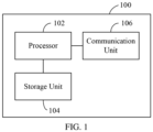
- FIG. 1 illustrates a block diagram of an apparatus 100 for estimating an angle of arrival (AoA) of signals according to one embodiment.
- the apparatus 100 acts with a User Equipment (UE), a base station, and a wireless transmitting/receiving unit (WTRU).
- the apparatus 100 comprises a processor 102, a storage unit 104, and a communication unit 106.
- the processor 102 controlling the apparatus 100 comprises a microcontroller, a microprocessor, or another circuit with processing capabilities, and executes or processes instructions, data, and computer programs stored in the storage unit 104.
- the storage unit 104 comprises a read-only memory (ROM), a random access memory (RAM), a magnetic disk storage medium device, an optical storage medium device, a flash memory device, electrical, optical, or other physical/tangible (e.g., non-transitory) memory device, etc.
- the storage unit 104 is used to store one or more computer programs that control the operation of the apparatus 100 and which are executed by the processor 102.
- the storage unit 104 stores or encodes one or more computer programs, and stores models, configurations, and computing parameters data, for the processor 102, to execute a method for estimating AOA according to various embodiments.
- the communication unit 106 performs functions for transmitting and receiving signals through a wireless channel.
- the communication unit 106 comprises a transmission filter, a reception filter, an amplifier, a mixer, an oscillator, a digital-to-analog converter (DAC), and an analog-to-digital converter (ADC).
- the communication unit 106 may comprise multiple transmission/reception paths. Further, the communication unit 106 may comprise an antenna array comprising a plurality of antenna elements.
- FIG. 2 illustrates a block diagram of an antenna array 200 of the communication unit 106 according to one embodiment.
- the antenna array 200 comprises M ⁇ antennas 202 and one ADC 204.
- the signals received at each antenna 202 are first phase-shifted, i.e., multiplied by the phase-shifter coefficient, and then summed up as the input of the ADC 204.
- the channel delay profile exists for every channel and link, respectively, formed by each beam arrangement between the receiving side and the transmitting side and indicates the intensity of a signal received through a multipath channel as a function of time delay.
- FIG. 3 shows, at Tap Delay 7, there are two taps with two different AoAs. This is the OCMA problem for the tap at Tap Delay 7.
- Various embodiments on AoA estimation for the tap with the OCMA problem in a wireless communication system are disclosed.
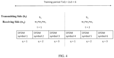
- FIG. 4 illustrates an example of a transmitting scheme of transmitting training blocks with different transmitting beamforming vectors such that different paths experience different transmit beamforming gains.
- T the number of training blocks
- the total number of OFDM symbols for the estimation is T ⁇ Q .
- the transmitting beamforming vectors b 1 , b 2 are different for different training blocks, but b t remains the same within each training block.
- the w q denoting the receiving beamforming vectors, varies within each block.
- FIG. 5 illustrates a method for estimating AoA performed by the apparatus 100 at the receiving side according to one embodiment.
- the method for estimating AoA comprises three stages.
- the first stage is to estimate the time-domain channel impulse response for each channel tap.
- the second stage uses different transmitting beamforming vectors with different receiving beamforming vectors to decouple the channel responses for each antenna element of the antenna array 200.
- the third stage is to calculate the correlation matrix and use a subspace-based algorithm such as Multiple Signal Classification (MUSIC), Estimation of Signal Parameters via Rotational Invariance Techniques (ESPRIT) to estimate multiple AoAs.
- MUSIC Multiple Signal Classification
- ESPRIT Rotational Invariance Techniques
- the channel estimation is implemented using pilot symbols.
- the pilot symbols may be transmitted by the transmitting side in the OFDM symbols at certain subcarriers.
- the pilot symbols have known values for both the transmitting side and the receiving side, thus the channel can be estimated using the pilot symbols.
- the apparatus 100 extracts pilot symbols from the received OFDM symbols.
- CIR channel impulse response
- the apparatus 100 estimates the time-domain CIR vector using a compressive sensing algorithm based on the extracted pilot symbols.
- the apparatus 100 uses an extended subspace pursuit algorithm, which exploits the property that h c ( q )'s share the same tap delay.
- the apparatus 100 recovers spatial channel responses based on the time-domain CIR vector.
- each channel tap is flat fading
- W is designed as a unitary or semi-unitary matrix to avoid amplification of noise.
- the apparatus 100 calculates a correlation matrix based on the recovered spatial channel responses.
- the tap delay of the i-th path is referred to as T i
- the T i -th row of H is referred to as y i T .
- some channel taps may contain responses of two paths or more.
- the apparatus 100 notifies the transmitting side to transmit training blocks with different transmitting beamforming vectors such that different channel paths will experience different channel gains.
- the transmitting beamforming vector b ( t ) of the transmitting side remains the same for each training block, and the receiving beamforming vector w ( q ) varies in each training block.
- h ( i ) ( t ) be the K i -by-1 channel gain vector for the i -th channel tap at the t-th transmission training block
- h ( i ) ( t ) be variant for the T blocks.
- the apparatus 100 performs singular value decomposition on the correlation matrix.
- step S512 the apparatus 100 determines whether a channel tap having multiple channel responses is caused by multiple signal paths.
- the apparatus 100 determines that the number of path responses on the channel tap is equal to one, the apparatus 100 executes step S514, and when the apparatus determines that the number of path responses on the channel tap is more than one, the apparatus executes step S516.
- the apparatus 100 estimates AoA of the one path response using a line-fitting or correlation algorithm.
- the apparatus 100 estimates multiple AoAs of the multiple path responses using a subspace-based algorithm, such as MUSIC or ESPRIT.
- a subspace-based algorithm such as MUSIC or ESPRIT.
- the MUSIC algorithm uses the orthogonal subspace U O to find multiple AoAs by searching for the peaks of the function defined as f ⁇ ⁇ 1 ⁇ a H ⁇ U ⁇ O ⁇ 2 2 where ⁇ O is the estimation of orthogonal subspace due to the presence of additive error in (7). Since the signal-to-noise ratio (SNR) of the channel estimation is much higher than that of the received signal for the antennas (due to the fact P >> I ) , the non-white property of the error is not apparent. In this embodiment, M r should be larger than K to render the orthogonal subspace non-empty.
- the AoA estimation method and apparatus of the present disclosure resolve the OCMA problem with a hybrid antenna array.
- Conventional subspace based algorithms such as MUSIC and ESPRIT can be applied, and the number of AoAs that can be estimated by the method and the apparatus is not limited by the number of antennas.
Landscapes
- Engineering & Computer Science (AREA)
- Computer Networks & Wireless Communication (AREA)
- Signal Processing (AREA)
- Physics & Mathematics (AREA)
- Power Engineering (AREA)
- General Physics & Mathematics (AREA)
- Radar, Positioning & Navigation (AREA)
- Remote Sensing (AREA)
- Mathematical Physics (AREA)
- Electromagnetism (AREA)
- Radio Transmission System (AREA)
Description
- This application claims priority to
U.S. Provisional Patent Application No. 62/927,438, filed on October 29, 2019 U.S. Provisional Patent Application No. 62/928,414, filed on October 31, 2019 - The subject matter herein generally relates to radio communications.
-
US20050250564A1 discloses an adaptive antenna radio communication device comprises a divided band direction estimating unit for estimating the direction by calculating the cross correlations between a pilot signal and sub-carrier signals of the respective divided bands received by an array antenna and calculating a spatial profile from correlation matrices determined by combining the correlation values between antenna elements of the different sub-carriers according to the output of the cross correlation calculation; a divided band array weight creating unit for creating a weight of a receive array having a directional beam in the direction of estimation for each divided band; and a sub-carrier directivity creating unit for creating a directivity by multiplication-combining the created receive array weight with the corresponding sub-carrier signal. -
US20190212409A1 discloses a method for estimating angle information for a wireless communication system includes receiving, by a wireless transmit/receive unit (WTRU), a plurality of first training symbols during a first period of time, wherein the plurality of first training symbols is transmitted using a first transmit beamforming vector fixed during the first period of time and received using a first receive beamforming, vector varied during the first period of time; estimating, by the WTRU, a plurality of first channel delay values based on the plurality of first training symbols; estimating, by the WTRU, a plurality of first channel values based on the plurality of first channel delay values; and estimating, by the WTRU, a first angle value of a path of a wireless channel based on the plurality of first channel values. - Anwen Liao et al: "2D Unitary ESPRIT Based Super-Resolution Channel Estimation for Millimeter-Wave Massive MIMO With Hybrid Precoding", ARXIV.ORG, CORNELL UNIVERSITY LIBRARY, 30 October 2017, XP080832834 discloses Millimeter-wave (mmWave) massive multiple-input multiple-output (MIMO) with hybrid precoding is a promising technique for the future 5G wireless communications. Due to a large number of antennas but a much smaller number of radio frequency chains, estimating the high-dimensional mmWave massive MIMO channel will bring the large pilot overhead. To overcome this challenge, this paper proposes a super-resolution channel estimation scheme based on 2-D unitary ESPRIT algorithm. By exploiting the angular sparsity of mmWave channels, the continuously distributed angle of arrivals/departures (AoAs/AoDs) can be jointly estimated with high accuracy. Specifically, by designing the uplink training signals at both base station and mobile station, we first use low pilot overhead to estimate a low-dimensional effective channel, which has the same shift-invariance of array response as the high-dimensional mmWave MIMO channel to be estimated. From the low-dimensional effective channel, the super-resolution estimates of AoAs and AoDs can be jointly obtained by exploiting the 2-D unitary ESPRIT channel estimation algorithm. Furthermore, the associated path gains can be acquired based on the least squares criterion. Finally, we can reconstruct the high-dimensional mmWave MIMO channel according to the obtained AoAs, AoDs, and path gains. Simulation results have confirmed that the proposed scheme is superior to conventional schemes with a much lower pilot overhead.
- Millimeter-wave (mmWave) communication is a key element in the fifth generation (5G) New Radio (NR) wireless communication system. Severe propagation losses in the mmWave channel call for massive antenna array to conduct beamforming, thus a receiver has to know angle of arrival (AoA) information.
- In indoor environments, transmitted signals may propagate through multiple paths resulting in close time delays, which are not resolvable, this is the problem of one channel tap with multiple AoAs (OCMA).
- Thus, there is room for improvement within the art.
- Implementations of the present technology will now be described, by way of embodiment, with reference to the attached figures, wherein:
-
FIG. 1 is a block diagram of one embodiment of an apparatus for estimating the angle of arrival of the signal. -
FIG. 2 is a schematic block diagram of one embodiment of an antenna array of the apparatus ofFIG. 1 . -
FIG. 3 is an example of one embodiment of a channel delay profile obtained by the apparatus ofFIG. 1 . -
FIG. 4 is an example of one embodiment of a transmitting scheme at the transmitting side. -
FIG. 5 is a flowchart of one embodiment of a method for estimating the angle of arrival. - It will be appreciated that for simplicity and clarity of illustration, where appropriate, reference numerals have been repeated among the different figures to indicate corresponding or analogous elements. In addition, numerous specific details are set forth in order to provide a thorough understanding of the embodiments described herein. However, it will be understood by those of ordinary skill in the art that the embodiments described herein can be practiced without these specific details. In other instances, methods, procedures, and components have not been described in detail so as not to obscure the related relevant feature being described. Also, the description is not to be considered as limiting the scope of the embodiments described herein. The drawings are not necessarily to scale and the proportions of certain parts may be exaggerated to better illustrate details and features of the present disclosure.
- References to "an" or "one" embodiment in this disclosure are not necessarily to the same embodiment, and such references mean "at least one".
- In general, the word "module" as used hereinafter, refers to logic embodied in computing or firmware, or to a collection of software instructions, written in a programming language, such as Java, C, or assembly. One or more software instructions in the modules may be embedded in firmware, such as in an erasable programmable read-only memory (EPROM). The modules described herein may be implemented as either software and/or computing modules and may be stored in any type of non-transitory computer-readable medium or another storage device. Some non-limiting examples of non-transitory computer-readable media include CDs, DVDs, BLU-RAY, flash memory, and hard disk drives. The term "comprising", when utilized, means "including, but not necessarily limited to"; it specifically indicates open-ended inclusion or membership in a so-described combination, group, series, and the like.
-
FIG. 1 illustrates a block diagram of anapparatus 100 for estimating an angle of arrival (AoA) of signals according to one embodiment. Theapparatus 100 acts with a User Equipment (UE), a base station, and a wireless transmitting/receiving unit (WTRU). Theapparatus 100 comprises aprocessor 102, astorage unit 104, and acommunication unit 106. - The
processor 102 controlling theapparatus 100 comprises a microcontroller, a microprocessor, or another circuit with processing capabilities, and executes or processes instructions, data, and computer programs stored in thestorage unit 104. - The
storage unit 104 comprises a read-only memory (ROM), a random access memory (RAM), a magnetic disk storage medium device, an optical storage medium device, a flash memory device, electrical, optical, or other physical/tangible (e.g., non-transitory) memory device, etc. Thestorage unit 104 is used to store one or more computer programs that control the operation of theapparatus 100 and which are executed by theprocessor 102. In the embodiment, thestorage unit 104 stores or encodes one or more computer programs, and stores models, configurations, and computing parameters data, for theprocessor 102, to execute a method for estimating AOA according to various embodiments. - The
communication unit 106 performs functions for transmitting and receiving signals through a wireless channel. Thecommunication unit 106 comprises a transmission filter, a reception filter, an amplifier, a mixer, an oscillator, a digital-to-analog converter (DAC), and an analog-to-digital converter (ADC). Thecommunication unit 106 may comprise multiple transmission/reception paths. Further, thecommunication unit 106 may comprise an antenna array comprising a plurality of antenna elements. -
FIG. 2 illustrates a block diagram of anantenna array 200 of thecommunication unit 106 according to one embodiment. Theantenna array 200 comprises Mγ antennas 202 and oneADC 204. The signals received at eachantenna 202 are first phase-shifted, i.e., multiplied by the phase-shifter coefficient, and then summed up as the input of theADC 204. -
FIG. 3 illustrates an example of a channel delay profile of theantenna array 200 with Mγ = 4 antennas in a MIMO-OFDM system. The channel delay profile exists for every channel and link, respectively, formed by each beam arrangement between the receiving side and the transmitting side and indicates the intensity of a signal received through a multipath channel as a function of time delay. AsFIG. 3 shows, at Tap Delay 7, there are two taps with two different AoAs. This is the OCMA problem for the tap at Tap Delay 7. Various embodiments on AoA estimation for the tap with the OCMA problem in a wireless communication system are disclosed. - In one embodiment, Q consecutive OFDM symbols are transmitted at the transmitting side in a MIMO-OFDM system as training symbols for channel estimation. The transmission of Q consecutive OFDM symbols is referred to as a training block. In order to resolve the OCMA problem,
FIG. 4 illustrates an example of a transmitting scheme of transmitting training blocks with different transmitting beamforming vectors such that different paths experience different transmit beamforming gains. Let t be the index of each training block, and T be the number of training blocks, then the total number of OFDM symbols for the estimation is T × Q. As shown inFIG. 4 , the transmitting beamforming vectors b 1, b 2 are different for different training blocks, but bt remains the same within each training block. The wq , denoting the receiving beamforming vectors, varies within each block. -
FIG. 5 illustrates a method for estimating AoA performed by theapparatus 100 at the receiving side according to one embodiment. - In the embodiment, the method for estimating AoA comprises three stages. The first stage is to estimate the time-domain channel impulse response for each channel tap. The second stage uses different transmitting beamforming vectors with different receiving beamforming vectors to decouple the channel responses for each antenna element of the
antenna array 200. The third stage is to calculate the correlation matrix and use a subspace-based algorithm such as Multiple Signal Classification (MUSIC), Estimation of Signal Parameters via Rotational Invariance Techniques (ESPRIT) to estimate multiple AoAs. - The detailed steps of the method are shown in
FIG. 5 . - In order to remove distortion from the received input signals, the effects of the channels need to be estimated. In one embodiment, the channel estimation is implemented using pilot symbols. The pilot symbols may be transmitted by the transmitting side in the OFDM symbols at certain subcarriers. The pilot symbols have known values for both the transmitting side and the receiving side, thus the channel can be estimated using the pilot symbols.
- At step S502, the
apparatus 100 extracts pilot symbols from the received OFDM symbols. The extracted pilot symbols x̃ 1 , ...., x̃P are expressed as a diagonal matrix X̃ = diag{x̃ 1, ..., x̃P }. The partial Discrete Fourier Transform (DFT) matrix of size P × L, where L is the length of the cyclic prefix (CP), is denoted as F. Then the noiseless frequency-domain received signal at P pilot-subcarriers, beamformed by the hybrid antenna array of theapparatus 100, at the q-th received OFDM symbol can be expressed as:
where F̃ = X̃F, and hc (q) is the spare beamformed time-domain channel impulse response (CIR) vector with I (I << L) non-zero entries at the q-th received OFDM symbol. - At step S504, the
apparatus 100 estimates the time-domain CIR vector using a compressive sensing algorithm based on the extracted pilot symbols. In one embodiment, theapparatus 100 uses an extended subspace pursuit algorithm, which exploits the property that hc (q)'s share the same tap delay. - At step S506, the
apparatus 100 recovers spatial channel responses based on the time-domain CIR vector. - In one embodiment, hc (q) can be expressed as a linear combination of CIRs for all antennas:

- where hm is the CIR for the m-th antenna. Next, for a matrix as the collection of hc (q)'s as

- where W is defined as the receiving beamforming matrix. Thus, H can be obtained as H = HcW † , where (.)† represents the pseudo-inverse of a square or over-determined matrix, indicating that W must be of full row rank (Q ≥ Mγ ).
- In one embodiment, with multiple transmissions at the transmitting side, the measurements lost in the spatial domain can be compensated for by those obtained in the time domain. In this embodiment, each channel tap is flat fading, and W is designed as a unitary or semi-unitary matrix to avoid amplification of noise.
- At step S508, for each channel tap delay, the
apparatus 100 calculates a correlation matrix based on the recovered spatial channel responses. - In one embodiment, the tap delay of the i-th path is referred to as Ti, and the Ti -th row of H is referred to as

apparatus 100 uses yi , which is the corresponding channel estimation vector:
- where a(θi ) is the steering vector for the i-th path. From (4), the (θi ) can be obtained by a simple correlation-based method, given by

- where Ø̂ i,Cor is the phase difference of two consecutive elements in the steering vector, θ̂i,Cor is the estimated AoA, [.] and (.)* are the complex conjugate of a scalar.

- In some situations, some channel taps may contain responses of two paths or more. To address this problem, (4) can be re-written as

- where Ki is the total number of channel impulse responses corresponding to different paths sampled by i-th channel tap delay, and h (i) is a Ki -by-1 vector consisting of the channel gains of the i-th channel tap delay. In one embodiment, allowing for channel estimation error, the
apparatus 100 can be modeled as;
- where ei is the channel estimation error vector, which is non-white in general.
- To resolve the OCMA problem, the
apparatus 100 notifies the transmitting side to transmit training blocks with different transmitting beamforming vectors such that different channel paths will experience different channel gains. As illustrated inFIG. 4 , the transmitting beamforming vector b(t) of the transmitting side remains the same for each training block, and the receiving beamforming vector w(q) varies in each training block. Letting h (i)(t) be the Ki -by-1 channel gain vector for the i-th channel tap at the t-th transmission training block, and h (i)(t) be variant for the T blocks. Theapparatus 100 can calculate the correlation matrix as;
where
(i) ) = Ki, meaning that T ≥ Ki. - At step S510, the
apparatus 100 performs singular value decomposition on the correlation matrix. - At step S512 the
apparatus 100 determines whether a channel tap having multiple channel responses is caused by multiple signal paths. When theapparatus 100 determines that the number of path responses on the channel tap is equal to one, theapparatus 100 executes step S514, and when the apparatus determines that the number of path responses on the channel tap is more than one, the apparatus executes step S516. - At step S514, the
apparatus 100 estimates AoA of the one path response using a line-fitting or correlation algorithm. - At step S516, the
apparatus 100 estimates multiple AoAs of the multiple path responses using a subspace-based algorithm, such as MUSIC or ESPRIT. - In one embodiment, the
apparatus 100 performs singular value decomposition on Rŷi = AR h(i) AH, and obtains
where

- Then, the MUSIC algorithm uses the orthogonal subspace UO to find multiple AoAs by searching for the peaks of the function defined as

where ÛO is the estimation of orthogonal subspace due to the presence of additive error in (7). Since the signal-to-noise ratio (SNR) of the channel estimation is much higher than that of the received signal for the antennas (due to the fact P >> I), the non-white property of the error is not apparent. In this embodiment, Mr should be larger than K to render the orthogonal subspace non-empty. - In one embodiment, span(A) = span(US ), hence there exists a unique and invertible matrix P such that AP = US. Although P is unknown, US can be used to find θ i,1, ... , θi,K as follows:

- where φ = diagl{e -jπ sin θi ,1, ...,e -jπ(Mr -1)sin θi,Ki }, (.) odd denotes the sub-matrix consisting of the odd rows of the matrix, and (.) even denotes the sub-matrix consisting of the even rows of the matrix. By rearranging (11), obtain:

- Mr /2 ≥ Ki, P -1 φP can be obtained by the least-squares or total-least-squares methods. It is shown that φ is a diagonal matrix containing the eigenvalues of P -1 φP. After φ is obtained, the multiple AoAs, θ i,1, ..., θi,K
i , can be derived easily. - The AoA estimation method and apparatus of the present disclosure resolve the OCMA problem with a hybrid antenna array. Conventional subspace based algorithms such as MUSIC and ESPRIT can be applied, and the number of AoAs that can be estimated by the method and the apparatus is not limited by the number of antennas.
- The embodiments shown and described above are only examples. Many details are often found in the art, therefore, many such details are neither shown nor described. Even though numerous characteristics and advantages of the present technology have been set forth in the foregoing description, together with details of the structure and function of the present disclosure, the disclosure is illustrative only, and changes may be made in the detail, especially in matters of shape, size, and arrangement of the parts within the principles of the present disclosure, up to and including the full extent established by the broad general meaning of the terms used in the claims. It will, therefore, be appreciated that the embodiments described above may be modified within the scope of the claims.
Claims (9)
- A method for estimating angle of arrival of signals in a wireless communication system include a transmitting side and a receiving side, the method comprising:receiving, by the receiving side, a plurality of signals transmitted by the transmitting side, characterised in that the plurality of signals transmitted by the transmitting side further comprises a plurality of training blocks and each one of the plurality of training block comprises a plurality of consecutive Orthogonal Frequency Division Multiplexing (OFDM) symbols, wherein the OFDM symbols comprise pilot symbols at certain subcarriers, the plurality of training blocks are transmitted by the transmitting side using different transmitting beamforming vectors, and the plurality of consecutive OFDM symbols of each one of the plurality of training blocks are received by the receiving side using different receiving beamforming vectors;extracting, by the receiving side, a plurality of pilot symbols from the received signals (S502);estimating, by the receiving side, time-domain channel responses using a compressive sensing algorithm based on the extracted pilot symbols (S504);recovering, by the receiving side, spatial channel responses based on the estimated time-domain channel responses (S506);obtaining, by the receiving side, a plurality of channel taps based on the recovered spatial channel responses;calculating, by the receiving side, a correlation matrix, for each one of the plurality of channel taps, based on the recovered spatial channel responses (S508);performing, by the receiving side, singular value decomposition on the correlation matrix for each one of the plurality of channel taps to obtain a singular value representation of the correlation matrix (S510);determining, by the receiving side, a number of responses caused by different paths for each one of the plurality of channel taps (S512); andestimating, by the receiving side, angle of arrival, for each one of the plurality of channel taps, based on the determined number of responses and the singular value representation of the correlation matrix (S516).
- The method of claim 1, the step of estimating angle of arrival, by the receiving side, for each one of the plurality of channel taps, based on the determined number of responses and the singular value representation of the correlation matrix, further comprises:
estimating angle of arrival using a line-fitting algorithm when the determined number is equal to one. - The method of claim 1, the step of estimating angle of arrival, by the receiving side, for each one of the plurality of channel taps, based on the determined number of responses and the singular value representation of the correlation matrix, further comprises:
estimating angle of arrival using a subspace-based algorithm when the determined number of channel responses is larger than one. - The method of claim 3, wherein the subspace-based algorithm further comprises: a Multiple Signal Classification (MUSIC) algorithm and a Estimation of Signal Parameters via Rotational Invariance Techniques (ESPRIT) algorithm.
- The method of claim 1, wherein the transmitting side and the receiving side are each comprised of multiple antennas in a multiple-input and multiple-output (MIMO) wireless communication system.
- The method of claim 5, wherein the multiple antennas of the receiving side further comprise a hybrid antenna array.
- An apparatus for estimating angle of arrival of signals, working as a receiving side, in a wireless communication system, wherein the wireless communication system further comprises a transmitting side, the apparatus comprising:a communication unit (106);a processor (102); anda storage unit (104) for storing at least one computer program, wherein the at least one computer program comprises instructions which are executed by the processor, and performs a method comprising:receiving, by the communication unit, a plurality of signals transmitted by the transmitting side, characterised in that the plurality of signals transmitted by the transmitting side further comprises a plurality of training blocks and each one of the plurality of training block comprises a plurality of consecutive Orthogonal Frequency Division Multiplexing (OFDM) symbols, wherein the OFDM symbols comprise pilot symbols at certain subcarriers, the plurality of training blocks are transmitted by the transmitting side using different transmitting beamforming vectors, and the plurality of consecutive OFDM symbols of each one of the plurality of training blocks are received by the receiving side using different receiving beamforming vectors;extracting a plurality of pilot symbols from the received signals;estimating time-domain channel responses using a compressive sensing algorithm based on the extracted pilot symbols;recovering spatial channel responses based on the estimated time-domain channel responses;obtaining a plurality of channel taps based on the recovered spatial channel responses;calculating a correlation matrix, for each one of the plurality of channel taps, based on the recovered spatial channel responses;performing singular value decomposition on the correlation matrix, for each one of the plurality of channel taps, to obtain a singular value representation of the correlation matrix;determining a number of responses caused by different paths for each one of the plurality of channel taps; andestimating angle of arrival, for each one of the plurality of channel taps, based on the determined number of responses and the singular value representation of the correlation matrix.
- The apparatus of claim 7, the step of estimating angle of arrival, for each one of the plurality of channel taps, based on the determined number of responses and the singular value representation of the correlation matrix, further comprises:
estimating angle of arrival using a line-fitting algorithm when the determined number is equal to one. - The apparatus of claim 7, the step of estimating angle of arrival, for each one of the plurality of channel taps, based on the determined number of responses and the singular value representation of the correlation matrix, further comprises:
estimating angle of arrival using a subspace-based algorithm when the determined number of channel responses is larger than one.
Applications Claiming Priority (2)
| Application Number | Priority Date | Filing Date | Title |
|---|---|---|---|
| US201962927438P | 2019-10-29 | 2019-10-29 | |
| US201962928414P | 2019-10-31 | 2019-10-31 |
Publications (2)
| Publication Number | Publication Date |
|---|---|
| EP3817312A1 EP3817312A1 (en) | 2021-05-05 |
| EP3817312B1 true EP3817312B1 (en) | 2024-11-06 |
Family
ID=73029987
Family Applications (1)
| Application Number | Title | Priority Date | Filing Date |
|---|---|---|---|
| EP20204232.1A Active EP3817312B1 (en) | 2019-10-29 | 2020-10-28 | Method and apparatus for estimating angle of arrival of signals in wireless communication system |
Country Status (4)
| Country | Link |
|---|---|
| US (1) | US20210124006A1 (en) |
| EP (1) | EP3817312B1 (en) |
| CN (1) | CN112752289A (en) |
| TW (1) | TWI745104B (en) |
Families Citing this family (11)
| Publication number | Priority date | Publication date | Assignee | Title |
|---|---|---|---|---|
| US11683661B2 (en) * | 2020-05-14 | 2023-06-20 | Qualcomm Incorporated | Communicating peak magnitude data associated with a reference signal for positioning |
| US11374796B2 (en) * | 2020-10-15 | 2022-06-28 | Samsung Electronics Co., Ltd. | Compressive sensing based channel recovery considering time variation of the channel |
| US11582029B2 (en) * | 2020-11-18 | 2023-02-14 | Kabushiki Kaisha Toshiba | Secret key generation for wireless channels |
| US12085657B2 (en) | 2021-06-04 | 2024-09-10 | Apple Inc. | Techniques to disambiguate angle of arrival |
| CN113938220B (en) * | 2021-10-12 | 2023-09-05 | 中国联合网络通信集团有限公司 | Wireless channel detection method, device, electronic equipment and storage medium |
| CN113945887B (en) * | 2021-10-18 | 2022-11-22 | 珠海极海半导体有限公司 | Positioning and direction finding system and method and BLE positioning device |
| KR102516903B1 (en) | 2021-11-11 | 2023-04-03 | 한국전자통신연구원 | Method and apparatus for simultaneous power estimation of multiple signal sources in communication system |
| JP2023111290A (en) * | 2022-01-31 | 2023-08-10 | 矢崎総業株式会社 | Direction-of-arrival estimation device and method for estimating direction of arrival of radio waves |
| JP2023176988A (en) * | 2022-06-01 | 2023-12-13 | 矢崎総業株式会社 | Direction of arrival estimation device and direction of arrival estimation method |
| JP2024000187A (en) * | 2022-06-20 | 2024-01-05 | 日本電気株式会社 | Learning device, angle of arrival estimation device, angle of arrival estimation system, learning model generation method, angle of arrival estimation method, and program |
| US20240171245A1 (en) * | 2022-11-17 | 2024-05-23 | Electronics And Telecommunications Research Institute | Apparatus and method for configuring pcc/scc prioritization based on extremely sparse channel information in wireless communication system |
Family Cites Families (10)
| Publication number | Priority date | Publication date | Assignee | Title |
|---|---|---|---|---|
| JP3888189B2 (en) * | 2002-03-12 | 2007-02-28 | 松下電器産業株式会社 | Adaptive antenna base station equipment |
| JP4309110B2 (en) * | 2002-09-27 | 2009-08-05 | パナソニック株式会社 | Adaptive antenna wireless communication device |
| KR100655661B1 (en) * | 2004-12-09 | 2006-12-11 | 한국전자통신연구원 | Space-time multi-user signal detection apparatus of array antenna base station and method thereof |
| WO2007028278A1 (en) * | 2005-09-08 | 2007-03-15 | Huawei Technologies Co., Ltd. | Estimation method for direction of arrival and means thereof |
| JP2012504886A (en) * | 2008-10-06 | 2012-02-23 | エレクトロビット・システム・テスト・オサケユキテュア | Wireless test |
| KR101426862B1 (en) * | 2013-03-19 | 2014-08-07 | 국방과학연구소 | 3 Dimension Array Antenna System and Altitude Angle Estimation Method thereof |
| WO2018045330A1 (en) * | 2016-09-02 | 2018-03-08 | Marvell Semiconductor, Inc. | Method and apparatus for determining an angle of arrival of a wireless signal |
| US20180131540A1 (en) * | 2016-11-04 | 2018-05-10 | Qualcomm Incorporated | Estimating timing and angle information of wireless signals |
| US20190086505A1 (en) * | 2017-09-20 | 2019-03-21 | Qualcomm Incorporated | Methods for estimating angle of arrival or angle of departure |
| CN110034804B (en) * | 2018-01-11 | 2022-11-29 | 南宁富联富桂精密工业有限公司 | Method and apparatus for estimating angle information for wireless communication system |
-
2020
- 2020-09-17 US US17/023,718 patent/US20210124006A1/en not_active Abandoned
- 2020-09-28 TW TW109133735A patent/TWI745104B/en active
- 2020-09-28 CN CN202011043944.9A patent/CN112752289A/en active Pending
- 2020-10-28 EP EP20204232.1A patent/EP3817312B1/en active Active
Also Published As
| Publication number | Publication date |
|---|---|
| US20210124006A1 (en) | 2021-04-29 |
| CN112752289A (en) | 2021-05-04 |
| EP3817312A1 (en) | 2021-05-05 |
| TW202130134A (en) | 2021-08-01 |
| TWI745104B (en) | 2021-11-01 |
Similar Documents
| Publication | Publication Date | Title |
|---|---|---|
| EP3817312A1 (en) | Method and apparatus for estimating angle of arrival of signals in wireless communication system | |
| US8638871B2 (en) | System and method for combination multiple input, multiple output (MIMO) and beamforming | |
| US10886986B2 (en) | Estimation of channel conditions | |
| US9722679B2 (en) | Method and apparatus for estimating communication channel in mobile communication system | |
| Peken et al. | Blind channel estimation for massive MIMO | |
| US11012131B2 (en) | Method for hybrid precoding and communication device | |
| JP7004062B2 (en) | Wireless device and channel prediction method | |
| EP4311373A2 (en) | Methods and devices for processing uplink signals | |
| Zhang et al. | Channel estimation and training design for hybrid multi-carrier mmWave massive MIMO systems: The beamspace ESPRIT approach | |
| US10270624B2 (en) | Channel estimation method and apparatus for use in wireless communication system | |
| Kim et al. | Two-step approach to time-domain channel estimation for wideband millimeter wave systems with hybrid architecture | |
| Yu et al. | Blind and semi-blind channel estimation with fast convergence for MIMO-OFDM systems | |
| Zhang et al. | Channel estimation for hybrid multi-carrier mmwave MIMO systems using three-dimensional unitary esprit in DFT beamspace | |
| US20190212409A1 (en) | Methods and devices for estimating angle information for wireless communication systems | |
| JP2007159130A (en) | Uplink reception method and apparatus in distributed antenna mobile communication system | |
| Zhang et al. | Channel estimation and training design for hybrid analog-digital multi-carrier single-user massive MIMO systems | |
| CN106452531B (en) | A Multi-User Uplink Frequency Synchronization Method Based on Massive MIMO | |
| US9787356B2 (en) | System and method for large dimension equalization using small dimension equalizers | |
| JP2008283393A (en) | Mmse equalizing circuit, receiving device, communication system, its method, and program | |
| Boljanovic et al. | Compressive estimation of wideband mmW channel using analog true-time-delay array | |
| CN103379048A (en) | Channel estimation and detection method and base station | |
| Guvensen et al. | Beamspace aware adaptive channel estimation for single-carrier time-varying massive MIMO channels | |
| CN119071109A (en) | Millimeter wave mMIMO channel estimation method and system based on neural network | |
| US9843417B2 (en) | Differential MIMO transceiver | |
| Gaber et al. | Joint time delay and DOA estimation using 2-D matrix pencil algorithms and IEEE 802.11 ac |
Legal Events
| Date | Code | Title | Description |
|---|---|---|---|
| PUAI | Public reference made under article 153(3) epc to a published international application that has entered the european phase |
Free format text: ORIGINAL CODE: 0009012 |
|
| STAA | Information on the status of an ep patent application or granted ep patent |
Free format text: STATUS: THE APPLICATION HAS BEEN PUBLISHED |
|
| AK | Designated contracting states |
Kind code of ref document: A1 Designated state(s): AL AT BE BG CH CY CZ DE DK EE ES FI FR GB GR HR HU IE IS IT LI LT LU LV MC MK MT NL NO PL PT RO RS SE SI SK SM TR |
|
| STAA | Information on the status of an ep patent application or granted ep patent |
Free format text: STATUS: REQUEST FOR EXAMINATION WAS MADE |
|
| 17P | Request for examination filed |
Effective date: 20210817 |
|
| RBV | Designated contracting states (corrected) |
Designated state(s): AL AT BE BG CH CY CZ DE DK EE ES FI FR GB GR HR HU IE IS IT LI LT LU LV MC MK MT NL NO PL PT RO RS SE SI SK SM TR |
|
| STAA | Information on the status of an ep patent application or granted ep patent |
Free format text: STATUS: EXAMINATION IS IN PROGRESS |
|
| 17Q | First examination report despatched |
Effective date: 20220909 |
|
| GRAP | Despatch of communication of intention to grant a patent |
Free format text: ORIGINAL CODE: EPIDOSNIGR1 |
|
| STAA | Information on the status of an ep patent application or granted ep patent |
Free format text: STATUS: GRANT OF PATENT IS INTENDED |
|
| INTG | Intention to grant announced |
Effective date: 20240802 |
|
| GRAS | Grant fee paid |
Free format text: ORIGINAL CODE: EPIDOSNIGR3 |
|
| GRAA | (expected) grant |
Free format text: ORIGINAL CODE: 0009210 |
|
| STAA | Information on the status of an ep patent application or granted ep patent |
Free format text: STATUS: THE PATENT HAS BEEN GRANTED |
|
| AK | Designated contracting states |
Kind code of ref document: B1 Designated state(s): AL AT BE BG CH CY CZ DE DK EE ES FI FR GB GR HR HU IE IS IT LI LT LU LV MC MK MT NL NO PL PT RO RS SE SI SK SM TR |
|
| REG | Reference to a national code |
Ref country code: GB Ref legal event code: FG4D |
|
| REG | Reference to a national code |
Ref country code: CH Ref legal event code: EP |
|
| REG | Reference to a national code |
Ref country code: DE Ref legal event code: R096 Ref document number: 602020040735 Country of ref document: DE |
|
| REG | Reference to a national code |
Ref country code: IE Ref legal event code: FG4D |
|
| REG | Reference to a national code |
Ref country code: LT Ref legal event code: MG9D |
|
| REG | Reference to a national code |
Ref country code: NL Ref legal event code: MP Effective date: 20241106 |
|
| PG25 | Lapsed in a contracting state [announced via postgrant information from national office to epo] |
Ref country code: HR Free format text: LAPSE BECAUSE OF FAILURE TO SUBMIT A TRANSLATION OF THE DESCRIPTION OR TO PAY THE FEE WITHIN THE PRESCRIBED TIME-LIMIT Effective date: 20241106 Ref country code: IS Free format text: LAPSE BECAUSE OF FAILURE TO SUBMIT A TRANSLATION OF THE DESCRIPTION OR TO PAY THE FEE WITHIN THE PRESCRIBED TIME-LIMIT Effective date: 20250306 Ref country code: PT Free format text: LAPSE BECAUSE OF FAILURE TO SUBMIT A TRANSLATION OF THE DESCRIPTION OR TO PAY THE FEE WITHIN THE PRESCRIBED TIME-LIMIT Effective date: 20250306 |
|
| PG25 | Lapsed in a contracting state [announced via postgrant information from national office to epo] |
Ref country code: FI Free format text: LAPSE BECAUSE OF FAILURE TO SUBMIT A TRANSLATION OF THE DESCRIPTION OR TO PAY THE FEE WITHIN THE PRESCRIBED TIME-LIMIT Effective date: 20241106 Ref country code: NL Free format text: LAPSE BECAUSE OF FAILURE TO SUBMIT A TRANSLATION OF THE DESCRIPTION OR TO PAY THE FEE WITHIN THE PRESCRIBED TIME-LIMIT Effective date: 20241106 |
|
| REG | Reference to a national code |
Ref country code: AT Ref legal event code: MK05 Ref document number: 1740606 Country of ref document: AT Kind code of ref document: T Effective date: 20241106 |
|
| PG25 | Lapsed in a contracting state [announced via postgrant information from national office to epo] |
Ref country code: BG Free format text: LAPSE BECAUSE OF FAILURE TO SUBMIT A TRANSLATION OF THE DESCRIPTION OR TO PAY THE FEE WITHIN THE PRESCRIBED TIME-LIMIT Effective date: 20241106 |
|
| PG25 | Lapsed in a contracting state [announced via postgrant information from national office to epo] |
Ref country code: ES Free format text: LAPSE BECAUSE OF FAILURE TO SUBMIT A TRANSLATION OF THE DESCRIPTION OR TO PAY THE FEE WITHIN THE PRESCRIBED TIME-LIMIT Effective date: 20241106 |
|
| PG25 | Lapsed in a contracting state [announced via postgrant information from national office to epo] |
Ref country code: NO Free format text: LAPSE BECAUSE OF FAILURE TO SUBMIT A TRANSLATION OF THE DESCRIPTION OR TO PAY THE FEE WITHIN THE PRESCRIBED TIME-LIMIT Effective date: 20250206 |
|
| PG25 | Lapsed in a contracting state [announced via postgrant information from national office to epo] |
Ref country code: LV Free format text: LAPSE BECAUSE OF FAILURE TO SUBMIT A TRANSLATION OF THE DESCRIPTION OR TO PAY THE FEE WITHIN THE PRESCRIBED TIME-LIMIT Effective date: 20241106 Ref country code: GR Free format text: LAPSE BECAUSE OF FAILURE TO SUBMIT A TRANSLATION OF THE DESCRIPTION OR TO PAY THE FEE WITHIN THE PRESCRIBED TIME-LIMIT Effective date: 20250207 Ref country code: AT Free format text: LAPSE BECAUSE OF FAILURE TO SUBMIT A TRANSLATION OF THE DESCRIPTION OR TO PAY THE FEE WITHIN THE PRESCRIBED TIME-LIMIT Effective date: 20241106 |
|
| PG25 | Lapsed in a contracting state [announced via postgrant information from national office to epo] |
Ref country code: PL Free format text: LAPSE BECAUSE OF FAILURE TO SUBMIT A TRANSLATION OF THE DESCRIPTION OR TO PAY THE FEE WITHIN THE PRESCRIBED TIME-LIMIT Effective date: 20241106 |
|
| PG25 | Lapsed in a contracting state [announced via postgrant information from national office to epo] |
Ref country code: RS Free format text: LAPSE BECAUSE OF FAILURE TO SUBMIT A TRANSLATION OF THE DESCRIPTION OR TO PAY THE FEE WITHIN THE PRESCRIBED TIME-LIMIT Effective date: 20250206 |
|
| PG25 | Lapsed in a contracting state [announced via postgrant information from national office to epo] |
Ref country code: SM Free format text: LAPSE BECAUSE OF FAILURE TO SUBMIT A TRANSLATION OF THE DESCRIPTION OR TO PAY THE FEE WITHIN THE PRESCRIBED TIME-LIMIT Effective date: 20241106 |
|
| PG25 | Lapsed in a contracting state [announced via postgrant information from national office to epo] |
Ref country code: DK Free format text: LAPSE BECAUSE OF FAILURE TO SUBMIT A TRANSLATION OF THE DESCRIPTION OR TO PAY THE FEE WITHIN THE PRESCRIBED TIME-LIMIT Effective date: 20241106 |
|
| PG25 | Lapsed in a contracting state [announced via postgrant information from national office to epo] |
Ref country code: EE Free format text: LAPSE BECAUSE OF FAILURE TO SUBMIT A TRANSLATION OF THE DESCRIPTION OR TO PAY THE FEE WITHIN THE PRESCRIBED TIME-LIMIT Effective date: 20241106 |
|
| PG25 | Lapsed in a contracting state [announced via postgrant information from national office to epo] |
Ref country code: RO Free format text: LAPSE BECAUSE OF FAILURE TO SUBMIT A TRANSLATION OF THE DESCRIPTION OR TO PAY THE FEE WITHIN THE PRESCRIBED TIME-LIMIT Effective date: 20241106 |
|
| PG25 | Lapsed in a contracting state [announced via postgrant information from national office to epo] |
Ref country code: SK Free format text: LAPSE BECAUSE OF FAILURE TO SUBMIT A TRANSLATION OF THE DESCRIPTION OR TO PAY THE FEE WITHIN THE PRESCRIBED TIME-LIMIT Effective date: 20241106 |
|
| PG25 | Lapsed in a contracting state [announced via postgrant information from national office to epo] |
Ref country code: CZ Free format text: LAPSE BECAUSE OF FAILURE TO SUBMIT A TRANSLATION OF THE DESCRIPTION OR TO PAY THE FEE WITHIN THE PRESCRIBED TIME-LIMIT Effective date: 20241106 |
|
| PG25 | Lapsed in a contracting state [announced via postgrant information from national office to epo] |
Ref country code: IT Free format text: LAPSE BECAUSE OF FAILURE TO SUBMIT A TRANSLATION OF THE DESCRIPTION OR TO PAY THE FEE WITHIN THE PRESCRIBED TIME-LIMIT Effective date: 20241106 |
|
| REG | Reference to a national code |
Ref country code: DE Ref legal event code: R097 Ref document number: 602020040735 Country of ref document: DE |
|
| PG25 | Lapsed in a contracting state [announced via postgrant information from national office to epo] |
Ref country code: SE Free format text: LAPSE BECAUSE OF FAILURE TO SUBMIT A TRANSLATION OF THE DESCRIPTION OR TO PAY THE FEE WITHIN THE PRESCRIBED TIME-LIMIT Effective date: 20241106 |
|
| PLBE | No opposition filed within time limit |
Free format text: ORIGINAL CODE: 0009261 |
|
| STAA | Information on the status of an ep patent application or granted ep patent |
Free format text: STATUS: NO OPPOSITION FILED WITHIN TIME LIMIT |
|
| 26N | No opposition filed |
Effective date: 20250807 |