EP3817158B1 - Contact module, and female connector and male connector - Google Patents
Contact module, and female connector and male connector Download PDFInfo
- Publication number
- EP3817158B1 EP3817158B1 EP19841884.0A EP19841884A EP3817158B1 EP 3817158 B1 EP3817158 B1 EP 3817158B1 EP 19841884 A EP19841884 A EP 19841884A EP 3817158 B1 EP3817158 B1 EP 3817158B1
- Authority
- EP
- European Patent Office
- Prior art keywords
- female
- male
- contact
- ground
- signal
- Prior art date
- Legal status (The legal status is an assumption and is not a legal conclusion. Google has not performed a legal analysis and makes no representation as to the accuracy of the status listed.)
- Active
Links
Images




Classifications
-
- H—ELECTRICITY
- H01—ELECTRIC ELEMENTS
- H01R—ELECTRICALLY-CONDUCTIVE CONNECTIONS; STRUCTURAL ASSOCIATIONS OF A PLURALITY OF MUTUALLY-INSULATED ELECTRICAL CONNECTING ELEMENTS; COUPLING DEVICES; CURRENT COLLECTORS
- H01R13/00—Details of coupling devices of the kinds covered by groups H01R12/70 or H01R24/00 - H01R33/00
- H01R13/02—Contact members
- H01R13/10—Sockets for co-operation with pins or blades
- H01R13/11—Resilient sockets
- H01R13/112—Resilient sockets forked sockets having two legs
-
- H—ELECTRICITY
- H01—ELECTRIC ELEMENTS
- H01R—ELECTRICALLY-CONDUCTIVE CONNECTIONS; STRUCTURAL ASSOCIATIONS OF A PLURALITY OF MUTUALLY-INSULATED ELECTRICAL CONNECTING ELEMENTS; COUPLING DEVICES; CURRENT COLLECTORS
- H01R12/00—Structural associations of a plurality of mutually-insulated electrical connecting elements, specially adapted for printed circuits, e.g. printed circuit boards [PCB], flat or ribbon cables, or like generally planar structures, e.g. terminal strips, terminal blocks; Coupling devices specially adapted for printed circuits, flat or ribbon cables, or like generally planar structures; Terminals specially adapted for contact with, or insertion into, printed circuits, flat or ribbon cables, or like generally planar structures
- H01R12/70—Coupling devices
- H01R12/71—Coupling devices for rigid printing circuits or like structures
- H01R12/712—Coupling devices for rigid printing circuits or like structures co-operating with the surface of the printed circuit or with a coupling device exclusively provided on the surface of the printed circuit
- H01R12/716—Coupling device provided on the PCB
-
- H—ELECTRICITY
- H01—ELECTRIC ELEMENTS
- H01R—ELECTRICALLY-CONDUCTIVE CONNECTIONS; STRUCTURAL ASSOCIATIONS OF A PLURALITY OF MUTUALLY-INSULATED ELECTRICAL CONNECTING ELEMENTS; COUPLING DEVICES; CURRENT COLLECTORS
- H01R13/00—Details of coupling devices of the kinds covered by groups H01R12/70 or H01R24/00 - H01R33/00
- H01R13/02—Contact members
- H01R13/04—Pins or blades for co-operation with sockets
-
- H—ELECTRICITY
- H01—ELECTRIC ELEMENTS
- H01R—ELECTRICALLY-CONDUCTIVE CONNECTIONS; STRUCTURAL ASSOCIATIONS OF A PLURALITY OF MUTUALLY-INSULATED ELECTRICAL CONNECTING ELEMENTS; COUPLING DEVICES; CURRENT COLLECTORS
- H01R13/00—Details of coupling devices of the kinds covered by groups H01R12/70 or H01R24/00 - H01R33/00
- H01R13/02—Contact members
- H01R13/04—Pins or blades for co-operation with sockets
- H01R13/05—Resilient pins or blades
-
- H—ELECTRICITY
- H01—ELECTRIC ELEMENTS
- H01R—ELECTRICALLY-CONDUCTIVE CONNECTIONS; STRUCTURAL ASSOCIATIONS OF A PLURALITY OF MUTUALLY-INSULATED ELECTRICAL CONNECTING ELEMENTS; COUPLING DEVICES; CURRENT COLLECTORS
- H01R13/00—Details of coupling devices of the kinds covered by groups H01R12/70 or H01R24/00 - H01R33/00
- H01R13/02—Contact members
- H01R13/10—Sockets for co-operation with pins or blades
- H01R13/11—Resilient sockets
-
- H—ELECTRICITY
- H01—ELECTRIC ELEMENTS
- H01R—ELECTRICALLY-CONDUCTIVE CONNECTIONS; STRUCTURAL ASSOCIATIONS OF A PLURALITY OF MUTUALLY-INSULATED ELECTRICAL CONNECTING ELEMENTS; COUPLING DEVICES; CURRENT COLLECTORS
- H01R13/00—Details of coupling devices of the kinds covered by groups H01R12/70 or H01R24/00 - H01R33/00
- H01R13/02—Contact members
- H01R13/22—Contacts for co-operating by abutting
- H01R13/24—Contacts for co-operating by abutting resilient; resiliently-mounted
- H01R13/2442—Contacts for co-operating by abutting resilient; resiliently-mounted with a single cantilevered beam
-
- H—ELECTRICITY
- H01—ELECTRIC ELEMENTS
- H01R—ELECTRICALLY-CONDUCTIVE CONNECTIONS; STRUCTURAL ASSOCIATIONS OF A PLURALITY OF MUTUALLY-INSULATED ELECTRICAL CONNECTING ELEMENTS; COUPLING DEVICES; CURRENT COLLECTORS
- H01R13/00—Details of coupling devices of the kinds covered by groups H01R12/70 or H01R24/00 - H01R33/00
- H01R13/646—Details of coupling devices of the kinds covered by groups H01R12/70 or H01R24/00 - H01R33/00 specially adapted for high-frequency, e.g. structures providing an impedance match or phase match
- H01R13/6461—Means for preventing cross-talk
- H01R13/6471—Means for preventing cross-talk by special arrangement of ground and signal conductors, e.g. GSGS [Ground-Signal-Ground-Signal]
-
- H—ELECTRICITY
- H01—ELECTRIC ELEMENTS
- H01R—ELECTRICALLY-CONDUCTIVE CONNECTIONS; STRUCTURAL ASSOCIATIONS OF A PLURALITY OF MUTUALLY-INSULATED ELECTRICAL CONNECTING ELEMENTS; COUPLING DEVICES; CURRENT COLLECTORS
- H01R13/00—Details of coupling devices of the kinds covered by groups H01R12/70 or H01R24/00 - H01R33/00
- H01R13/648—Protective earth or shield arrangements on coupling devices, e.g. anti-static shielding
-
- H—ELECTRICITY
- H01—ELECTRIC ELEMENTS
- H01R—ELECTRICALLY-CONDUCTIVE CONNECTIONS; STRUCTURAL ASSOCIATIONS OF A PLURALITY OF MUTUALLY-INSULATED ELECTRICAL CONNECTING ELEMENTS; COUPLING DEVICES; CURRENT COLLECTORS
- H01R13/00—Details of coupling devices of the kinds covered by groups H01R12/70 or H01R24/00 - H01R33/00
- H01R13/648—Protective earth or shield arrangements on coupling devices, e.g. anti-static shielding
- H01R13/652—Protective earth or shield arrangements on coupling devices, e.g. anti-static shielding with earth pin, blade or socket
-
- H—ELECTRICITY
- H01—ELECTRIC ELEMENTS
- H01R—ELECTRICALLY-CONDUCTIVE CONNECTIONS; STRUCTURAL ASSOCIATIONS OF A PLURALITY OF MUTUALLY-INSULATED ELECTRICAL CONNECTING ELEMENTS; COUPLING DEVICES; CURRENT COLLECTORS
- H01R13/00—Details of coupling devices of the kinds covered by groups H01R12/70 or H01R24/00 - H01R33/00
- H01R13/648—Protective earth or shield arrangements on coupling devices, e.g. anti-static shielding
- H01R13/658—High frequency shielding arrangements, e.g. against EMI [Electro-Magnetic Interference] or EMP [Electro-Magnetic Pulse]
- H01R13/6581—Shield structure
- H01R13/6585—Shielding material individually surrounding or interposed between mutually spaced contacts
-
- H—ELECTRICITY
- H01—ELECTRIC ELEMENTS
- H01R—ELECTRICALLY-CONDUCTIVE CONNECTIONS; STRUCTURAL ASSOCIATIONS OF A PLURALITY OF MUTUALLY-INSULATED ELECTRICAL CONNECTING ELEMENTS; COUPLING DEVICES; CURRENT COLLECTORS
- H01R12/00—Structural associations of a plurality of mutually-insulated electrical connecting elements, specially adapted for printed circuits, e.g. printed circuit boards [PCB], flat or ribbon cables, or like generally planar structures, e.g. terminal strips, terminal blocks; Coupling devices specially adapted for printed circuits, flat or ribbon cables, or like generally planar structures; Terminals specially adapted for contact with, or insertion into, printed circuits, flat or ribbon cables, or like generally planar structures
- H01R12/70—Coupling devices
- H01R12/71—Coupling devices for rigid printing circuits or like structures
- H01R12/72—Coupling devices for rigid printing circuits or like structures coupling with the edge of the rigid printed circuits or like structures
- H01R12/73—Coupling devices for rigid printing circuits or like structures coupling with the edge of the rigid printed circuits or like structures connecting to other rigid printed circuits or like structures
Definitions
- the present invention relates to high-speed connectors, and in particular, to a female connector and a male connector.
- a high-speed differential connector is generally provided with a shielding structure for shielding each signal transmission circuit so as to avoid crosstalk between adjacent signal transmission circuits.
- Existing are various types of high-speed differential connectors.
- a relatively common connector for example, a fully shielded differential connector disclosed in the present application of CN 104300313A , the differential pairs are arranged in a row, ground contacts are arranged between every two adjacent differential pairs, wiring shielding members are arranged between every two adjacent differential pairs, and during plugging, the differential pairs and the ground contacts are attached on the same side to the differential pairs and the ground contacts of an adapter connector are.
- This differential connector has a high degree of integration and is widely used.
- the above connector when applied to a vibration environment or a plugging position requiring certain offset, the above connector tends to cause uneven stress at the plugging part by adopting single-sided contact and accordingly affect the transmission performance of the connector. Furthermore, all the contact modules are elastically attached to one another through the same side to cause that the entire connector is subjected to the lateral force from the same direction when being plugged and thereby bears high plugging resistance.
- the patent application US 2014 0017950 A1 discloses a female connector, comprising a connector housing internally provided with a female contact module, the female contact module comprises female signal contacts which are arranged in pairs and a female ground contact arranged corresponding to the female signal contacts, one end of each female contact module is a socket end at which the female ground contact and the female signal contacts arranged in pairs are arranged to form an elastic clamping structure, a plugging space for plugging a male contact module is formed between the female signal contacts and the female ground contact, and a female signal contact portion is arranged on one side of each female signal contact facing the female ground contact for elastically abutting against the corresponding male signal contact of a male contact module which is provided with paired male signal contact and male ground contact; one side of female ground contact facing the female signal contact is provided with a female shielding contact portion, which is used for elastically abutting against the corresponding male ground contact of the male contact module which is provided with paired male signal contact and male ground contact, wherein the female contact module further comprises a female end
- That patent application also discloses a corresponding male connector, comprising a connector housing in which a male contact module is mounted, the male contact module comprises male signal contacts arranged in pairs and a male ground contact arranged corresponding to the male signal contacts, and one end of the male contact module is a plug end which is fit to be plugged into the plugging space of the female connector when in use, at the plug end, one side of each male signal contact away from the corresponding male ground contact is provided with a male signal contact portion for elastically abutting against the corresponding female signal contact of the female contact module which are provided with the female signal contacts arranged in pairs and the female ground contact, and the male ground contact comprises a male end ground shielding housing, the male end ground shielding housing is integrally provided with a male end ground overhung segment on a side opposite to the plugging portions of the male signal contacts, a male shielding contact portion, as part of the male end ground overhung segment, is used for conductive contact with the corresponding female ground contact of the fitting female contact module, which is provided with the female signal contacts
- the shielding shell structure of the female connector in this patent is complex and not conducive to production and manufacturing.
- An object of the present invention is to provide a female connector and a male connector which are adapted to each other, so as to solve the problem that plug-in modules bearing single-sided elastic stress are affected in transmission performance and high in plugging resistance.
- a female connector comprises a connector housing; a female contact unit is mounted in the connector housing; the female contact unit comprises female signal contacts arranged in pairs and female ground contact arranged corresponding to the female signal contact arranged in pairs; one end of each female contact unit is a socket end; at the socket end, the female ground contacts arranged in pairs and the female signal contacts arranged in pairs form an elastic clamping structure; a plugging space for plugging a male contact unit is formed between the female signal contacts and the female ground contacts; a female signal contact portion is arranged on one side of each female signal contact facing the corresponding female ground contact for elastically abutting against the corresponding male signal contact of a male contact unit which are provided with the male signal contacts arranged in pairs and male ground contacts; a female shielding contact portion is arranged on one side of each female ground contact facing the corresponding female signal contact for elastically abutting against the corresponding male ground contact of the male contact unit which are provided with the male signal contacts arranged in pairs and the male ground contacts.
- the male contact unit is elastically clamped in the middle by the female signal contact and the female ground contact and correspondingly conducted, so that the contact modules of the two connectors adapted in the plugging position bear interaction forces on both sides, and even during application on occasions with vibration or certain plugging offset, vibration displacement or plugging offset can be compensated by the elastic deformation of the elastic clamping structure to improve the contact reliability of the plugging position and the performance be more reliable.
- the side surface of the elastic overhung segments of female signal contact facing the female ground contact is provided with the female signal contact portion for conductive contact with the male contact unit
- the side surface of the elastic overhung segments of female ground contact facing the female signal contact is provided with the female shielding contact portion for conductive contact with the corresponding male ground contact
- the female contact unit further comprises a female end module insulator
- the female signal contacts arranged in pairs are mounted in the female end module insulator
- each of the female ground contact comprises a cylindrical shielding shell circumferentially wrapping the female end module insulator
- elastic overhung segments of each female signal contact extend out of one end of the cylindrical shielding shell
- elastic overhung segments of the female ground contact is provided on the cylindrical shielding shell on a side opposite to the elastic overhung segments of female signal contact. Since the elastic overhung segments are subjected to lateral force, the elastic overhung segments of the ground contacts can be arranged on the cylindrical shielding shells wrapping the insulator so as to ensure reliable connection between the shielding shells and the insulator.
- the cylindrical shielding shell is formed by winding a material strip and then overlapping two ends of the material strip.
- the female contact unit further includes a female end module insulator, a pair of female signal contacts and corresponding female ground contacts are fixed to the female end module insulator to form a female contact module, and a plurality of the female contact modules can be mounted in the connector housing.
- the contact unit is configured to be formed by modules, thereby achieving modularization and convenient disassembly and assembly.
- the male connector of the present invention comprises a connector housing, a male contact unit is mounted in the connector housing, the male contact unit comprises male signal contacts arranged in pairs and a male ground contact arranged corresponding to the male signal contacts, one end of the male contact unit is a plug end plugged into the plugging space of the female connector when in use, at the plug end, one side of each male signal contact away from the corresponding male ground contact is provided with a male signal contact portion for elastically abutting against the corresponding female signal contact of the female contact unit which are provided with the female signal contacts arranged in pairs and the female ground contacts arranged in pairs, and the male ground contact comprises a male end ground shielding housing, the male end ground shielding housing is integrally provided with a male end ground overhung segment on a side opposite to the plugging portions of the male signal contacts, a male shielding contact portion, as part of the male end ground overhung segment, is used for conductive contact with the corresponding female ground contact of the female contact unit which are provided with the female signal contacts arranged in pairs and the female ground
- the male contact unit When the male connector of the present invention is in use, the male contact unit is clamped in the plugging space of the female contact unit, so that the contact modules of the two connectors adapted in the plugging position bear interaction forces on both sides, and even during application on occasions with vibration or certain plugging offset is used, the contact reliability of the plugging position can be improved and the performance be more reliable.
- the male contact unit further comprises a unit insulator at the plug end, the unit insulator is provided with an insulating support portion arranged between the male signal contacts and the male ground contacts for providing support when the male signal contacts and the male ground contacts of the male contact unit elastically abut against the female signal contacts and the female ground contacts, so as to ensure reliable contact of the signal contacts and the ground contacts when adapted contacts elastically abut.
- a pair of male signal contacts and the corresponding male ground contacts are fixed to the unit insulator to form a male contact module, and a plurality of the male contact modules can be mounted in the connector housing.
- the contact unit is configured to be formed by a module, thereby achieving modularization and convenient disassembly and assembly.
- the male ground contact is of a U-shaped structure and half-enclose the male signal contacts arranged in pairs the insulating support portion is filled in the inner groove of a U-shaped shielding piece and exposes a side surface of the signal pair facing the notch, and both male signal contacts are located on the exposed side surface. Therefore, two side edges of the U-shaped portion of each ground contact can achieve certain shielding effects on the signal contacts therein, and the shielding effects can be good.
- each male ground contact comprises a cylindrical shielding shell circumferentially wrapping the unit insulator. and the U-shaped ground contact at the plug end and the cylindrical shielding shell are of an integral structure.
- an embodiment of the female connector of the present invention comprises a female end housing 1, a plurality of mounting grooves are formed in the female end housing 1, female contact modules 2 are mounted in the mounting grooves, each female contact module 2 comprises a female end module insulator 20, female signal contacts arranged in pairs are mounted in the female end module insulator 20, the female contact module further comprises female ground contacts, each female ground contact comprises a female ground shielding housing 22 wrapping outside the female end module insulator 20, and the female signal contacts extend out of the female end module insulator 20 from the end openings of the female end ground shielding housing 22.
- the female end ground shielding housing 22 is fixed relatively to the female end housing 1 by a barb structure 223 provided thereon.
- each female signal contact extending out of the female module insulator 20 is a terminal which is specifically a fisheye structure 212 used for connecting a printed board in this embodiment, and the other end is a signal overhung segment 210.
- a ground overhung segment 220 is provided on the female shielding housing 22 on a side opposite to (not limited to directly opposite to) the female signal contact, and a ground fish-eye 222 is provided on the other end.
- the signal overhung segment and the ground overhung segment form a plugging segment
- the side surface of each female signal contact facing the female ground contact is provided with a female signal contact portion 211 for conductive contact with the male contact unit
- the side surface of each female ground contact facing the female signal contact is provided with a female shielding contact portion 221 for conductive contact with the corresponding male ground contact
- the space in the elastic clamping opening which is formed by the signal overhung segment and the ground overhung segment serves as a plugging space for plugging a male contact module.
- the ground overhung segment 220 extending from the shielding shell of the female ground contact is an integral overhung piece, while in Fig. 5 , the ground overhung segment 220 extending from the shielding shell of the female ground contact are split overhung arms, and the two split overhung arms are substantially opposite to the two signal overhung segments.
- the female ground contact may be of an elongated chip structure, namely not including the ground shielding housing structure wrapping the female end module insulator in the above-mentioned embodiment.
- a part of the female signal contacts and the female ground contacts of the female connector are mounted in the same insulator, for example, the same row of contact units are arranged in one insulator, or all of the female signal contacts and all the female ground contacts are mounted in the same insulator, namely without adopting a modular mounting mode.
- the male connector of the present invention is shown in Figs. 8 , 9 and 10 , and in the embodiment takes an adapter connector as an example, and of course in other embodiments can be a single-end plugged plug or a socket connector.
- the male connector comprises a male end housing 3, a plurality of mounting grooves are form in the male end housing 3, male contact modules 4 are mounted in the mounting grooves, each male contact module 4 comprises a unit insulator 40, male signal contacts 41 arranged in pairs are mounted in the unit insulator 40, each male contact module 4 further comprises a male ground contact, each male ground contact comprises a male end ground shielding housing 42 wrapping outside the unit insulator 40, and the male signal contacts 41 extend out of the two end openings of the male end ground shielding housing 42.
- both ends of the male contact module are plug ends, and both ends of each male signal contact 41 extending out of the unit insulator 40 are plugging portions for plugging the female connector.
- the male ground contacts may be of an elongated strip structure, namely not including the ground shielding housing structure wrapping the male module insulator in the above-mentioned embodiment.
- the male end ground shielding housing 42 is integrally provided with a male end ground overhung segment 420 on a side opposite to the plugging portions of the male signal contacts 41, and the male end ground overhung segment 420 is used for being plugged into the female contact module.
- the side surface of the male signal contact away from the male ground contact is provided with a male signal contact portion for conductive contact with the corresponding female signal contact
- the side surface of the male ground contact away from the male signal contact of the male end ground overhung segment 420 is provided with a male shielding contact portion for conductive contact with the corresponding female ground contact.
- the unit insulator 40 is provided with an insulating support portion 44 between the male signal contacts and the male ground contacts for providing support when the male signal contacts and the male ground contacts elastically abut against the female signal contacts and the female ground contacts respectively, so as to ensure reliable contact between the male signal contacts and the male ground contacts when adapted contacts elastically abut.
- the male end ground overhung segment 420 is of a U-shaped structure and half-encloses a pair of male signal contacts, the insulating support portion 44 is filled in the inner groove of the U-shaped shielding piece and exposes the side surface of the signal pair facing the notch, and the male signal contacts are located on the exposed side surface. Therefore, two side edges of the male end ground overhung segment 420 of the U-shaped structure can achieve certain shielding effects on the male signal contacts therein, and the shielding effects can be good.
- the male connector of the present invention is not limited to the above-mentioned embodiments, but in other non-claimed embodiments, the male end ground overhung segment may be of a flat board structure; the insulating support portion may not be provided between the male ground overhung segment and the plug end of the male signal contacts, so that both can be of a free overhung structure.
- the male signal contacts and the male ground contacts may be in contact with the adapted female contacts through their own overhanging elasticity, and correspondingly, the socket end of the female signal contacts and the female ground contacts may be fixed relative to the insulator.
- a part of the male signal contacts and male ground contacts may also be mounted in the same insulator, for example, the same row of contact units are arranged in one insulator, or all male signal contacts and male ground contacts are mounted in the same insulator, namely without a modular mounting mode.
- both the male and female ground contacts and the male and female signal contacts of are all arranged in pairs and spaced from each other, while in other non-claimed embodiments, the ground contacts and the signal contacts can be arranged opposite to and spaced from each other only at the plug and socket ends, but can be located on the same plane in the insulator.
- the plug end of the contact module of the male connector is clamped in the plugging space formed by the socket end of the female contact module, so that the contact pieces of the two connectors adapted at the plugging position bear interaction forces on both sides, and even during application on occasions with vibration or certain plugging offset, the contact reliability of the plugging position can be improved and the performance be more reliable.
Landscapes
- Details Of Connecting Devices For Male And Female Coupling (AREA)
Description
- The present invention relates to high-speed connectors, and in particular, to a female connector and a male connector.
- With the development trend of miniaturization, densification and integration, the application of high-speed differential connectors becomes more and more extensive. Due to the large number of transmitted signals, a high-speed differential connector is generally provided with a shielding structure for shielding each signal transmission circuit so as to avoid crosstalk between adjacent signal transmission circuits. Existing are various types of high-speed differential connectors. In a relatively common connector, for example, a fully shielded differential connector disclosed in the present application of
CN 104300313A , the differential pairs are arranged in a row, ground contacts are arranged between every two adjacent differential pairs, wiring shielding members are arranged between every two adjacent differential pairs, and during plugging, the differential pairs and the ground contacts are attached on the same side to the differential pairs and the ground contacts of an adapter connector are. This differential connector has a high degree of integration and is widely used. - However, when applied to a vibration environment or a plugging position requiring certain offset, the above connector tends to cause uneven stress at the plugging part by adopting single-sided contact and accordingly affect the transmission performance of the connector. Furthermore, all the contact modules are elastically attached to one another through the same side to cause that the entire connector is subjected to the lateral force from the same direction when being plugged and thereby bears high plugging resistance.
- The patent application
US 2014 0017950 A1 discloses a female connector, comprising a connector housing internally provided with a female contact module, the female contact module comprises female signal contacts which are arranged in pairs and a female ground contact arranged corresponding to the female signal contacts, one end of each female contact module is a socket end at which the female ground contact and the female signal contacts arranged in pairs are arranged to form an elastic clamping structure, a plugging space for plugging a male contact module is formed between the female signal contacts and the female ground contact, and a female signal contact portion is arranged on one side of each female signal contact facing the female ground contact for elastically abutting against the corresponding male signal contact of a male contact module which is provided with paired male signal contact and male ground contact; one side of female ground contact facing the female signal contact is provided with a female shielding contact portion, which is used for elastically abutting against the corresponding male ground contact of the male contact module which is provided with paired male signal contact and male ground contact, wherein the female contact module further comprises a female end module insulator, the female signal contacts arranged in pairs are mounted in the female end module insulator, the female ground contact comprises a shielding shell partially wrapping the female end module insulator, elastic overhung segments of the female signal contacts extend out of one end of the shielding shell, and elastic overhung segments of the female ground contact is provided on the shielding shell on a side opposite to the elastic overhung segments of female signal contacts, the side surface of the elastic overhung segments of female signal contact facing the female ground contact is provided with the female signal contact portion for conductive contact with the male contact unit, the side surface of the elastic overhung segments of female ground contact facing the female signal contact is provided with the female shielding contact portion for conductive contact with the corresponding male ground contact, and the space in the elastic clamping opening which is formed by the elastic overhung segments of female ground contact and elastic overhung segments of female signal contacts as a plugging space for plugging a male contact module. - That patent application also discloses a corresponding male connector, comprising a connector housing in which a male contact module is mounted, the male contact module comprises male signal contacts arranged in pairs and a male ground contact arranged corresponding to the male signal contacts, and one end of the male contact module is a plug end which is fit to be plugged into the plugging space of the female connector when in use, at the plug end, one side of each male signal contact away from the corresponding male ground contact is provided with a male signal contact portion for elastically abutting against the corresponding female signal contact of the female contact module which are provided with the female signal contacts arranged in pairs and the female ground contact, and the male ground contact comprises a male end ground shielding housing, the male end ground shielding housing is integrally provided with a male end ground overhung segment on a side opposite to the plugging portions of the male signal contacts, a male shielding contact portion, as part of the male end ground overhung segment, is used for conductive contact with the corresponding female ground contact of the fitting female contact module, which is provided with the female signal contacts arranged in pairs and the female ground contact, the male contact unit further comprises a unit insulator, and at the plug end, the unit insulator is provided with an insulating support portion arranged between the male signal contacts and the male ground contact for providing support when the male signal contacts and the male ground contact of the male contact module elastically abut against the female signal contacts and the female ground contact, at the plug end, the male ground contact is of a U-shaped structure and half-enclose the male signal contacts arranged in pairs, the insulating support portion is filled in the inner groove of the U-shaped structure and exposes a side surface of the pair of the male signal contacts facing the notch of the U-shaped structure, and both male signal contacts are located on the exposed side surface, the male ground contact comprises a shielding shell partially wrapping the unit insulator, and the U-shaped structure and the shielding shell are of an integral structure.
- However, the shielding shell structure of the female connector in this patent is complex and not conducive to production and manufacturing.
- An object of the present invention is to provide a female connector and a male connector which are adapted to each other, so as to solve the problem that plug-in modules bearing single-sided elastic stress are affected in transmission performance and high in plugging resistance.
- A female connector comprises a connector housing; a female contact unit is mounted in the connector housing; the female contact unit comprises female signal contacts arranged in pairs and female ground contact arranged corresponding to the female signal contact arranged in pairs; one end of each female contact unit is a socket end; at the socket end, the female ground contacts arranged in pairs and the female signal contacts arranged in pairs form an elastic clamping structure; a plugging space for plugging a male contact unit is formed between the female signal contacts and the female ground contacts; a female signal contact portion is arranged on one side of each female signal contact facing the corresponding female ground contact for elastically abutting against the corresponding male signal contact of a male contact unit which are provided with the male signal contacts arranged in pairs and male ground contacts; a female shielding contact portion is arranged on one side of each female ground contact facing the corresponding female signal contact for elastically abutting against the corresponding male ground contact of the male contact unit which are provided with the male signal contacts arranged in pairs and the male ground contacts.
- In the female connector of the present invention, the male contact unit is elastically clamped in the middle by the female signal contact and the female ground contact and correspondingly conducted, so that the contact modules of the two connectors adapted in the plugging position bear interaction forces on both sides, and even during application on occasions with vibration or certain plugging offset, vibration displacement or plugging offset can be compensated by the elastic deformation of the elastic clamping structure to improve the contact reliability of the plugging position and the performance be more reliable.
- Further, the side surface of the elastic overhung segments of female signal contact facing the female ground contact is provided with the female signal contact portion for conductive contact with the male contact unit, the side surface of the elastic overhung segments of female ground contact facing the female signal contact is provided with the female shielding contact portion for conductive contact with the corresponding male ground contact, and the space in the elastic clamping opening which is formed by the elastic overhung segments of female ground contact and elastic overhung segments of female signal contact as a plugging space for plugging a male contact module. Therefore, the structure is simple and the processing cost is low.
- Improvement is further performed on the basis and is that the female contact unit further comprises a female end module insulator, the female signal contacts arranged in pairs are mounted in the female end module insulator, each of the female ground contact comprises a cylindrical shielding shell circumferentially wrapping the female end module insulator, elastic overhung segments of each female signal contact extend out of one end of the cylindrical shielding shell, and elastic overhung segments of the female ground contact is provided on the cylindrical shielding shell on a side opposite to the elastic overhung segments of female signal contact. Since the elastic overhung segments are subjected to lateral force, the elastic overhung segments of the ground contacts can be arranged on the cylindrical shielding shells wrapping the insulator so as to ensure reliable connection between the shielding shells and the insulator.
- Of course, in order to facilitate the processing, the cylindrical shielding shell is formed by winding a material strip and then overlapping two ends of the material strip.
- In addition, the female contact unit further includes a female end module insulator, a pair of female signal contacts and corresponding female ground contacts are fixed to the female end module insulator to form a female contact module, and a plurality of the female contact modules can be mounted in the connector housing. The contact unit is configured to be formed by modules, thereby achieving modularization and convenient disassembly and assembly.
- The male connector of the present invention comprises a connector housing, a male contact unit is mounted in the connector housing, the male contact unit comprises male signal contacts arranged in pairs and a male ground contact arranged corresponding to the male signal contacts, one end of the male contact unit is a plug end plugged into the plugging space of the female connector when in use, at the plug end, one side of each male signal contact away from the corresponding male ground contact is provided with a male signal contact portion for elastically abutting against the corresponding female signal contact of the female contact unit which are provided with the female signal contacts arranged in pairs and the female ground contacts arranged in pairs, and the male ground contact comprises a male end ground shielding housing, the male end ground shielding housing is integrally provided with a male end ground overhung segment on a side opposite to the plugging portions of the male signal contacts, a male shielding contact portion, as part of the male end ground overhung segment, is used for conductive contact with the corresponding female ground contact of the female contact unit which are provided with the female signal contacts arranged in pairs and the female ground contacts arranged in pairs.
- When the male connector of the present invention is in use, the male contact unit is clamped in the plugging space of the female contact unit, so that the contact modules of the two connectors adapted in the plugging position bear interaction forces on both sides, and even during application on occasions with vibration or certain plugging offset is used, the contact reliability of the plugging position can be improved and the performance be more reliable.
- Further, the male contact unit further comprises a unit insulator at the plug end, the unit insulator is provided with an insulating support portion arranged between the male signal contacts and the male ground contacts for providing support when the male signal contacts and the male ground contacts of the male contact unit elastically abut against the female signal contacts and the female ground contacts, so as to ensure reliable contact of the signal contacts and the ground contacts when adapted contacts elastically abut.
- Further, a pair of male signal contacts and the corresponding male ground contacts are fixed to the unit insulator to form a male contact module, and a plurality of the male contact modules can be mounted in the connector housing. The contact unit is configured to be formed by a module, thereby achieving modularization and convenient disassembly and assembly.
- Specifically, at the plug end, the male ground contact is of a U-shaped structure and half-enclose the male signal contacts arranged in pairs the insulating support portion is filled in the inner groove of a U-shaped shielding piece and exposes a side surface of the signal pair facing the notch, and both male signal contacts are located on the exposed side surface. Therefore, two side edges of the U-shaped portion of each ground contact can achieve certain shielding effects on the signal contacts therein, and the shielding effects can be good.
- Meanwhile, optimization design is further performed and is that each male ground contact comprises a cylindrical shielding shell circumferentially wrapping the unit insulator. and the U-shaped ground contact at the plug end and the cylindrical shielding shell are of an integral structure.
-
-
FIG. 1 is a schematic structural diagram of a female connector according to the present invention; -
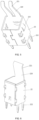
FIG. 2 is a schematic structural diagram of a female contact module according to the present invention; -
FIG. 3 is a front view of the female contact module; -
FIG. 4 is a left view ofFIG. 3 ; -
FIG. 5 is a schematic structural diagram of a ground contact of the female contact module; -
FIG. 6 is a schematic structural diagram of a ground contact of another female contact module; -
FIG. 7 is a schematic diagram of a combination of an insulator and a signal contact of the female contact module; -
FIG. 8 is a schematic structural diagram of a male connector; -
FIG. 9 is a schematic structural diagram of a male contact module; -
FIG. 10 is a schematic diagram of the plugging position shown inFIG. 9 ; -
FIG. 11 is a schematic diagram of the plugging process of the female contact module and the male contact module; - In the figure: 1-female end housing; 2-female contact module; 20-female end module insulator; 210-signal overhung segment; 211-female signal contact portion; 212-fisheye structure; 22-female end ground shielding shell; 220-ground overhung segment; 221-female shielding contact portion; 222-ground fisheye; 223-barb-shaped structure; 3-male end housing; 4-male contact module; 40-unit insulator; 41-male signal contact; a 42-male end ground shielding shell; 420-male end ground overhung segment; 44-insulating support portion.
- The embodiments of the present invention will be further described below with reference to the accompanying drawings.
- As shown in
Figs. 1-7 , an embodiment of the female connector of the present invention comprises a female end housing 1, a plurality of mounting grooves are formed in the female end housing 1,female contact modules 2 are mounted in the mounting grooves, eachfemale contact module 2 comprises a femaleend module insulator 20, female signal contacts arranged in pairs are mounted in the femaleend module insulator 20, the female contact module further comprises female ground contacts, each female ground contact comprises a femaleground shielding housing 22 wrapping outside the femaleend module insulator 20, and the female signal contacts extend out of the femaleend module insulator 20 from the end openings of the female endground shielding housing 22. The female endground shielding housing 22 is fixed relatively to the female end housing 1 by abarb structure 223 provided thereon. One end of each female signal contact extending out of thefemale module insulator 20 is a terminal which is specifically afisheye structure 212 used for connecting a printed board in this embodiment, and the other end is asignal overhung segment 210. Aground overhung segment 220 is provided on thefemale shielding housing 22 on a side opposite to (not limited to directly opposite to) the female signal contact, and a ground fish-eye 222 is provided on the other end. The signal overhung segment and the ground overhung segment form a plugging segment, the side surface of each female signal contact facing the female ground contact is provided with a femalesignal contact portion 211 for conductive contact with the male contact unit, the side surface of each female ground contact facing the female signal contact is provided with a femaleshielding contact portion 221 for conductive contact with the corresponding male ground contact, and the space in the elastic clamping opening which is formed by the signal overhung segment and the ground overhung segment serves as a plugging space for plugging a male contact module. - Various structures of the female ground contact are shown as in
Fig. 5 and Fig. 6 respectively which provide two different forms. InFig. 6 , theground overhung segment 220 extending from the shielding shell of the female ground contact is an integral overhung piece, while InFig. 5 , theground overhung segment 220 extending from the shielding shell of the female ground contact are split overhung arms, and the two split overhung arms are substantially opposite to the two signal overhung segments. Of course, in other embodiments which are not part of the present invention, the female ground contact may be of an elongated chip structure, namely not including the ground shielding housing structure wrapping the female end module insulator in the above-mentioned embodiment. - In addition, in other non-claimed embodiments, a part of the female signal contacts and the female ground contacts of the female connector are mounted in the same insulator, for example, the same row of contact units are arranged in one insulator, or all of the female signal contacts and all the female ground contacts are mounted in the same insulator, namely without adopting a modular mounting mode.
- The male connector of the present invention is shown in
Figs. 8 ,9 and 10 , and in the embodiment takes an adapter connector as an example, and of course in other embodiments can be a single-end plugged plug or a socket connector. The male connector comprises amale end housing 3, a plurality of mounting grooves are form in themale end housing 3,male contact modules 4 are mounted in the mounting grooves, eachmale contact module 4 comprises aunit insulator 40,male signal contacts 41 arranged in pairs are mounted in theunit insulator 40, eachmale contact module 4 further comprises a male ground contact, each male ground contact comprises a male endground shielding housing 42 wrapping outside theunit insulator 40, and themale signal contacts 41 extend out of the two end openings of the male endground shielding housing 42. Both ends of the male contact module are plug ends, and both ends of eachmale signal contact 41 extending out of theunit insulator 40 are plugging portions for plugging the female connector. Of course, in other embodiments which are not part of the present invention, the male ground contacts may be of an elongated strip structure, namely not including the ground shielding housing structure wrapping the male module insulator in the above-mentioned embodiment. - The male end
ground shielding housing 42 is integrally provided with a male endground overhung segment 420 on a side opposite to the plugging portions of themale signal contacts 41, and the male endground overhung segment 420 is used for being plugged into the female contact module. - As shown in
Fig. 11 , at the plug end, the side surface of the male signal contact away from the male ground contact is provided with a male signal contact portion for conductive contact with the corresponding female signal contact, and the side surface of the male ground contact away from the male signal contact of the male endground overhung segment 420 is provided with a male shielding contact portion for conductive contact with the corresponding female ground contact. - In the present embodiment, at the plug end, the
unit insulator 40 is provided with aninsulating support portion 44 between the male signal contacts and the male ground contacts for providing support when the male signal contacts and the male ground contacts elastically abut against the female signal contacts and the female ground contacts respectively, so as to ensure reliable contact between the male signal contacts and the male ground contacts when adapted contacts elastically abut. - In addition, at the plug end, the male end
ground overhung segment 420 is of a U-shaped structure and half-encloses a pair of male signal contacts, theinsulating support portion 44 is filled in the inner groove of the U-shaped shielding piece and exposes the side surface of the signal pair facing the notch, and the male signal contacts are located on the exposed side surface. Therefore, two side edges of the male endground overhung segment 420 of the U-shaped structure can achieve certain shielding effects on the male signal contacts therein, and the shielding effects can be good. - Of course, the male connector of the present invention is not limited to the above-mentioned embodiments, but in other non-claimed embodiments, the male end ground overhung segment may be of a flat board structure; the insulating support portion may not be provided between the male ground overhung segment and the plug end of the male signal contacts, so that both can be of a free overhung structure. In this case, the male signal contacts and the male ground contacts may be in contact with the adapted female contacts through their own overhanging elasticity, and correspondingly, the socket end of the female signal contacts and the female ground contacts may be fixed relative to the insulator.
- Furthermore, in other non-claimed embodiments, a part of the male signal contacts and male ground contacts may also be mounted in the same insulator, for example, the same row of contact units are arranged in one insulator, or all male signal contacts and male ground contacts are mounted in the same insulator, namely without a modular mounting mode.
- A variety of embodiments of the female connector and the male connector are provided above, respectively, wherein at the plug and socket ends and in the insulator, both the male and female ground contacts and the male and female signal contacts of are all arranged in pairs and spaced from each other, while in other non-claimed embodiments, the ground contacts and the signal contacts can be arranged opposite to and spaced from each other only at the plug and socket ends, but can be located on the same plane in the insulator.
- When the female and male connectors of the present invention are adapted in a plugging mode, the plug end of the contact module of the male connector is clamped in the plugging space formed by the socket end of the female contact module, so that the contact pieces of the two connectors adapted at the plugging position bear interaction forces on both sides, and even during application on occasions with vibration or certain plugging offset, the contact reliability of the plugging position can be improved and the performance be more reliable.
Claims (4)
- A female connector, comprising a connector housing internally provided with a female contact module (2), the female contact module comprises female signal contacts which are arranged in pairs and female ground contact overhung segments which are arranged corresponding to the female signal contacts arranged in pairs, one end of each female contact module is a socket end at which the female ground contact overhung segments and the female signal contacts arranged in pairs are arranged in pairs to form an elastic clamping structure, a plugging space for plugging a male contact module (4) is formed between the female signal contacts and the female ground contact overhung segments and a female signal contact portion (211) is arranged on one side of each female signal contact facing the corresponding female ground contact for elastically abutting against the corresponding male signal contact (41) of a male contact module (4), which is provided with paired male signal contact (41) and male ground contact; one side of each female ground contact segment facing the corresponding female signal contact is provided with a female shielding contact portion (221), which is used for elastically abutting against the corresponding male ground contact of the male contact module (4), which is provided with paired male signal contact (41) and male ground contact, wherein the female contact module (2) further comprises a female end module insulator (20), the female signal contacts arranged in pairs are mounted in the female end module insulator (20), the female ground contact comprises a cylindrical shielding shell circumferentially wrapping the female end module insulator (20), elastic overhung segments of each female signal contact extend out of one end of the cylindrical shielding shell, and elastic overhung segments of the female ground contact are provided on the cylindrical shielding shell on a side opposite to the elastic overhung segments of female signal contact, the side surface of the elastic overhung segments of female signal contact facing the female ground contact is provided with the female signal contact portion (221) for conductive contact with the male contact unit, the side surface of the elastic overhung segments of female ground contact facing the female signal contacts is provided with the female shielding contact portion (221) for conductive contact with the corresponding male ground contact, and the space in the elastic clamping opening which is formed by the elastic overhung segments of female ground contact and elastic overhung segments of female signal contacts as a plugging space for plugging a male contact module.
- The female connector according to claim 1, characterized in that a plurality of the female contact modules (2) are mounted in the connector housing.
- A male connector, comprising a connector housing in which a male contact module (4) is mounted, the male contact module (4) comprises male signal contacts (41) arranged in pairs and a male ground contact arranged corresponding to the male signal contacts (41), and one end of the male contact module(4) is a plug end which is adapted to be plugged into the plugging space of a female connector module when in use, at the plug end, one side of each male signal contact (41) away from the corresponding male ground contact is provided with a male signal contact portion for elastically abutting against the corresponding female signal contact of the female contact module (2) which are provided with the female signal contacts arranged in pairs and the female ground contacts arranged in pairs, and the male ground contact comprises a male end ground shielding housing (42), the male end ground shielding housing (42) is integrally provided with a male end ground overhung segment (420) on a side opposite to the plugging portions of the male signal contacts (41), a male shielding contact portion , as part of the male end ground overhung segment (420), is used for conductive contact with the corresponding female ground contacts of the female contact module (2), which are provided with the female signal contacts arranged in pairs and the female ground contacts arranged in pairs, wherein the male contact unit further comprises a unit insulator (40), and at the plug end, the unit insulator (40) is provided with an insulating support portion (44) arranged between the male signal contacts (41) and the male ground contacts for providing support when the male signal contacts and the male ground contacts of the male contact module (4) elastically abut against the female signal contacts and the female ground contacts, at the plug end, the male ground contact is of a U-shaped structure and half-enclose the male signal contacts (41) arranged in pairs, the insulating support portion is filled in the inner groove of the U-shaped structure and exposes a side surface of the pair of the male signal contacts (41) facing the notch of the U-shaped structure, and both male signal contacts are located on the exposed side surface, the male ground contact comprises a cylindrical shielding shell circumferentially wrapping the unit insulator (40), and the U-shaped structure and the cylindrical shielding shell are of an integral structure.
- The male connector according to claim 3, characterized in that a plurality of the male contact modules are mounted in the connector housing.
Applications Claiming Priority (2)
| Application Number | Priority Date | Filing Date | Title |
|---|---|---|---|
| CN201810847127.5A CN109659740B (en) | 2018-07-27 | 2018-07-27 | Contact modules with female and male connectors |
| PCT/CN2019/097706 WO2020020291A1 (en) | 2018-07-27 | 2019-07-25 | Contact module, and female connector and male connector |
Publications (4)
| Publication Number | Publication Date |
|---|---|
| EP3817158A1 EP3817158A1 (en) | 2021-05-05 |
| EP3817158A4 EP3817158A4 (en) | 2022-03-23 |
| EP3817158B1 true EP3817158B1 (en) | 2025-06-04 |
| EP3817158C0 EP3817158C0 (en) | 2025-06-04 |
Family
ID=66109961
Family Applications (1)
| Application Number | Title | Priority Date | Filing Date |
|---|---|---|---|
| EP19841884.0A Active EP3817158B1 (en) | 2018-07-27 | 2019-07-25 | Contact module, and female connector and male connector |
Country Status (4)
| Country | Link |
|---|---|
| US (1) | US11804674B2 (en) |
| EP (1) | EP3817158B1 (en) |
| CN (1) | CN109659740B (en) |
| WO (1) | WO2020020291A1 (en) |
Families Citing this family (11)
| Publication number | Priority date | Publication date | Assignee | Title |
|---|---|---|---|---|
| CN109659740B (en) | 2018-07-27 | 2020-09-08 | 中航光电科技股份有限公司 | Contact modules with female and male connectors |
| CN110299639B (en) * | 2019-06-21 | 2020-11-17 | 中航光电科技股份有限公司 | Socket shell, socket and switching coupling assembling |
| US11894628B2 (en) | 2020-06-18 | 2024-02-06 | Amphenol East Asia Electronic Technology (Shenzhen) Co., Ltd. | PCIe SAS direct link cable |
| US12300937B2 (en) * | 2021-08-13 | 2025-05-13 | Amphenol Commercial Products (Chengdu) Co., Ltd. | High speed electrical connector |
| CN215816686U (en) * | 2021-08-13 | 2022-02-11 | 安费诺东亚电子科技(深圳)有限公司 | Novel PSAS connector structure |
| JP2023100475A (en) * | 2022-01-06 | 2023-07-19 | 株式会社村田製作所 | Electrical connector and electrical connector set comprising the electrical connector |
| CN218275368U (en) | 2022-05-30 | 2023-01-10 | 安费诺商用电子产品(成都)有限公司 | plug connector |
| CN219144638U (en) | 2022-08-16 | 2023-06-06 | 安费诺商用电子产品(成都)有限公司 | Electric connector |
| TWM656437U (en) | 2022-08-31 | 2024-06-11 | 大陸商安費諾商用電子產品(成都)有限公司 | Electrical connector and connector subassembly |
| TW202412410A (en) | 2022-09-02 | 2024-03-16 | 大陸商安費諾商用電子產品(成都)有限公司 | High speed electrical connector |
| CN219040777U (en) | 2022-09-02 | 2023-05-16 | 安费诺商用电子产品(成都)有限公司 | Connector subassembly and electrical connector |
Citations (1)
| Publication number | Priority date | Publication date | Assignee | Title |
|---|---|---|---|---|
| US20140017950A1 (en) * | 2011-03-17 | 2014-01-16 | Molex Incorporated | Mezzanine connector with terminal brick |
Family Cites Families (25)
| Publication number | Priority date | Publication date | Assignee | Title |
|---|---|---|---|---|
| US6290515B1 (en) * | 2000-09-05 | 2001-09-18 | Hon Hai Precision Ind. Co., Ltd. | Electrical connector assembly having grounding buses |
| US6780059B1 (en) | 2003-06-26 | 2004-08-24 | Teradyne, Inc. | High speed, high density electrical connector |
| JP2007157534A (en) * | 2005-12-06 | 2007-06-21 | Japan Aviation Electronics Industry Ltd | Connector |
| JP5270480B2 (en) * | 2008-11-05 | 2013-08-21 | 富士通コンポーネント株式会社 | connector |
| US7985079B1 (en) * | 2010-04-20 | 2011-07-26 | Tyco Electronics Corporation | Connector assembly having a mating adapter |
| JP5426470B2 (en) * | 2010-05-11 | 2014-02-26 | 株式会社アドバンテスト | Connector and semiconductor test apparatus having the same |
| CN102738660B (en) * | 2011-03-31 | 2015-10-07 | 富士康(昆山)电脑接插件有限公司 | Electric connector and assembly thereof |
| JP5685502B2 (en) * | 2011-07-25 | 2015-03-18 | 株式会社アドバンテスト | Connector and semiconductor test equipment |
| JP6127199B2 (en) * | 2013-03-13 | 2017-05-10 | モレックス エルエルシー | Integrated signal-to-element and connector using the same |
| US9017103B2 (en) * | 2013-07-23 | 2015-04-28 | Tyco Electronics Corporation | Modular connector assembly |
| CN104300313B (en) | 2013-12-05 | 2017-02-15 | 中航光电科技股份有限公司 | Full-shielding-type difference connector |
| US9401569B2 (en) * | 2014-10-06 | 2016-07-26 | Tyco Electronics Corporation | Electrical connector assembly having signal modules and ground shields |
| US9407045B2 (en) * | 2014-12-16 | 2016-08-02 | Tyco Electronics Corporation | Electrical connector with joined ground shields |
| CN105789987B (en) * | 2014-12-25 | 2019-04-16 | 泰连公司 | Electric connector with ground frame |
| CN107112666B (en) * | 2015-01-11 | 2019-04-23 | 莫列斯有限公司 | Board Connector Assemblies, Connectors and Bypass Cable Assemblies |
| US9543676B2 (en) * | 2015-02-17 | 2017-01-10 | Tyco Electronics Corporation | Connector adapter and circuit board assembly including the same |
| JP6444775B2 (en) * | 2015-03-03 | 2018-12-26 | 富士通コンポーネント株式会社 | connector |
| US9531133B1 (en) * | 2015-12-14 | 2016-12-27 | Tyco Electronics Corporation | Electrical connector having lossy spacers |
| CN106169669B (en) * | 2016-06-24 | 2018-11-13 | 中航光电科技股份有限公司 | Radio frequency connector and its radio-frequency contact part and connector shell |
| US10128616B2 (en) * | 2016-07-25 | 2018-11-13 | Te Connectivity Corporation | Electrical connector having commoned ground shields |
| CN207925721U (en) * | 2018-01-30 | 2018-09-28 | 富誉电子科技(淮安)有限公司 | Power connector |
| US10665973B2 (en) * | 2018-03-22 | 2020-05-26 | Amphenol Corporation | High density electrical connector |
| US10498100B1 (en) * | 2018-07-06 | 2019-12-03 | Tyco Electronics Corporation | Electrical connector assembly having press tabs for seating tool |
| CN110707493B (en) * | 2018-07-10 | 2021-08-31 | 莫列斯有限公司 | Intermediate adapter connector and electric connector combination |
| CN109659740B (en) * | 2018-07-27 | 2020-09-08 | 中航光电科技股份有限公司 | Contact modules with female and male connectors |
-
2018
- 2018-07-27 CN CN201810847127.5A patent/CN109659740B/en active Active
-
2019
- 2019-07-25 US US17/251,187 patent/US11804674B2/en active Active
- 2019-07-25 WO PCT/CN2019/097706 patent/WO2020020291A1/en not_active Ceased
- 2019-07-25 EP EP19841884.0A patent/EP3817158B1/en active Active
Patent Citations (1)
| Publication number | Priority date | Publication date | Assignee | Title |
|---|---|---|---|---|
| US20140017950A1 (en) * | 2011-03-17 | 2014-01-16 | Molex Incorporated | Mezzanine connector with terminal brick |
Also Published As
| Publication number | Publication date |
|---|---|
| CN109659740A (en) | 2019-04-19 |
| EP3817158A4 (en) | 2022-03-23 |
| EP3817158C0 (en) | 2025-06-04 |
| US11804674B2 (en) | 2023-10-31 |
| CN109659740B (en) | 2020-09-08 |
| EP3817158A1 (en) | 2021-05-05 |
| US20210226386A1 (en) | 2021-07-22 |
| WO2020020291A1 (en) | 2020-01-30 |
Similar Documents
| Publication | Publication Date | Title |
|---|---|---|
| US11804674B2 (en) | Contact module, and female connector and male connector | |
| CN109599729B (en) | Connector and contact module thereof | |
| EP3639330B1 (en) | Electrical cable connector | |
| US11495900B2 (en) | Electrical connector adapter for connecting between two circuit board connectors | |
| US7128611B2 (en) | Electric connector including signal contact pairs and ground contacts provided in rows at a first end, in which the ground contacts are provided between signal contact pairs from the respective rows at a second end | |
| US8684772B2 (en) | Electrical connector | |
| KR101903986B1 (en) | Electrical Connector and Circuit Board Assembly | |
| CN112531384A (en) | Plug electric connector | |
| EP3467950B1 (en) | Connector | |
| CN102738660A (en) | Electrical connectors and their components | |
| CN110350349B (en) | Plug connectors for differential data transmission | |
| CN105098516A (en) | Interlayer type socket connector | |
| US6056560A (en) | High density plug connector unit | |
| TWI876604B (en) | Electrical connector | |
| US20020130728A1 (en) | Electrical connector and transmission line | |
| TWI608674B (en) | Signal transfering device and adapter assembly | |
| CN109659721B (en) | Signal transmission module, male end connector and female end connector | |
| TW201911685A (en) | Adapter assembly and adapter | |
| KR20200002868U (en) | High speed transmission board to board connector | |
| CN205122833U (en) | Electronic connector | |
| EP3312945A1 (en) | High speed network module socket connector | |
| CN216134011U (en) | Multi-pole connector | |
| CN111430957B (en) | Orthogonal direct contact type high-speed electric connector | |
| CN210517232U (en) | Cluster radio frequency coaxial connector | |
| CN222261616U (en) | Connector |
Legal Events
| Date | Code | Title | Description |
|---|---|---|---|
| STAA | Information on the status of an ep patent application or granted ep patent |
Free format text: STATUS: THE INTERNATIONAL PUBLICATION HAS BEEN MADE |
|
| PUAI | Public reference made under article 153(3) epc to a published international application that has entered the european phase |
Free format text: ORIGINAL CODE: 0009012 |
|
| STAA | Information on the status of an ep patent application or granted ep patent |
Free format text: STATUS: REQUEST FOR EXAMINATION WAS MADE |
|
| 17P | Request for examination filed |
Effective date: 20210201 |
|
| AK | Designated contracting states |
Kind code of ref document: A1 Designated state(s): AL AT BE BG CH CY CZ DE DK EE ES FI FR GB GR HR HU IE IS IT LI LT LU LV MC MK MT NL NO PL PT RO RS SE SI SK SM TR |
|
| RIN1 | Information on inventor provided before grant (corrected) |
Inventor name: MA, LUFEI Inventor name: YUAN, JUNFENG Inventor name: PAN, XIANJUN Inventor name: FU, JINHUI |
|
| RAP3 | Party data changed (applicant data changed or rights of an application transferred) |
Owner name: AVIC JONHON OPTRONIC TECHNOLOGY CO., LTD. Owner name: NOKIA SHANGHAI BELL CO., LTD. |
|
| DAV | Request for validation of the european patent (deleted) | ||
| DAX | Request for extension of the european patent (deleted) | ||
| REG | Reference to a national code |
Ref country code: DE Ipc: H01R0012710000 Ref country code: DE Ref legal event code: R079 Ref document number: 602019070855 Country of ref document: DE Free format text: PREVIOUS MAIN CLASS: H01R0013652000 Ipc: H01R0012710000 |
|
| A4 | Supplementary search report drawn up and despatched |
Effective date: 20220221 |
|
| RIC1 | Information provided on ipc code assigned before grant |
Ipc: H01R 13/24 20060101ALN20220215BHEP Ipc: H01R 12/73 20110101ALN20220215BHEP Ipc: H01R 13/6471 20110101ALI20220215BHEP Ipc: H01R 13/11 20060101ALI20220215BHEP Ipc: H01R 12/71 20110101AFI20220215BHEP |
|
| STAA | Information on the status of an ep patent application or granted ep patent |
Free format text: STATUS: EXAMINATION IS IN PROGRESS |
|
| 17Q | First examination report despatched |
Effective date: 20230907 |
|
| GRAP | Despatch of communication of intention to grant a patent |
Free format text: ORIGINAL CODE: EPIDOSNIGR1 |
|
| STAA | Information on the status of an ep patent application or granted ep patent |
Free format text: STATUS: GRANT OF PATENT IS INTENDED |
|
| INTG | Intention to grant announced |
Effective date: 20250103 |
|
| GRAS | Grant fee paid |
Free format text: ORIGINAL CODE: EPIDOSNIGR3 |
|
| GRAA | (expected) grant |
Free format text: ORIGINAL CODE: 0009210 |
|
| STAA | Information on the status of an ep patent application or granted ep patent |
Free format text: STATUS: THE PATENT HAS BEEN GRANTED |
|
| AK | Designated contracting states |
Kind code of ref document: B1 Designated state(s): AL AT BE BG CH CY CZ DE DK EE ES FI FR GB GR HR HU IE IS IT LI LT LU LV MC MK MT NL NO PL PT RO RS SE SI SK SM TR |
|
| REG | Reference to a national code |
Ref country code: GB Ref legal event code: FG4D |
|
| REG | Reference to a national code |
Ref country code: CH Ref legal event code: EP |
|
| REG | Reference to a national code |
Ref country code: DE Ref legal event code: R096 Ref document number: 602019070855 Country of ref document: DE |
|
| REG | Reference to a national code |
Ref country code: IE Ref legal event code: FG4D |
|
| U01 | Request for unitary effect filed |
Effective date: 20250626 |
|
| U07 | Unitary effect registered |
Designated state(s): AT BE BG DE DK EE FI FR IT LT LU LV MT NL PT RO SE SI Effective date: 20250703 |
|
| U20 | Renewal fee for the european patent with unitary effect paid |
Year of fee payment: 7 Effective date: 20250729 |
|
| PG25 | Lapsed in a contracting state [announced via postgrant information from national office to epo] |
Ref country code: ES Free format text: LAPSE BECAUSE OF FAILURE TO SUBMIT A TRANSLATION OF THE DESCRIPTION OR TO PAY THE FEE WITHIN THE PRESCRIBED TIME-LIMIT Effective date: 20250604 |
|
| PG25 | Lapsed in a contracting state [announced via postgrant information from national office to epo] |
Ref country code: NO Free format text: LAPSE BECAUSE OF FAILURE TO SUBMIT A TRANSLATION OF THE DESCRIPTION OR TO PAY THE FEE WITHIN THE PRESCRIBED TIME-LIMIT Effective date: 20250904 Ref country code: GR Free format text: LAPSE BECAUSE OF FAILURE TO SUBMIT A TRANSLATION OF THE DESCRIPTION OR TO PAY THE FEE WITHIN THE PRESCRIBED TIME-LIMIT Effective date: 20250905 |
|
| PG25 | Lapsed in a contracting state [announced via postgrant information from national office to epo] |
Ref country code: PL Free format text: LAPSE BECAUSE OF FAILURE TO SUBMIT A TRANSLATION OF THE DESCRIPTION OR TO PAY THE FEE WITHIN THE PRESCRIBED TIME-LIMIT Effective date: 20250604 |
|
| PG25 | Lapsed in a contracting state [announced via postgrant information from national office to epo] |
Ref country code: HR Free format text: LAPSE BECAUSE OF FAILURE TO SUBMIT A TRANSLATION OF THE DESCRIPTION OR TO PAY THE FEE WITHIN THE PRESCRIBED TIME-LIMIT Effective date: 20250604 |
|
| PG25 | Lapsed in a contracting state [announced via postgrant information from national office to epo] |
Ref country code: RS Free format text: LAPSE BECAUSE OF FAILURE TO SUBMIT A TRANSLATION OF THE DESCRIPTION OR TO PAY THE FEE WITHIN THE PRESCRIBED TIME-LIMIT Effective date: 20250904 |
|
| PG25 | Lapsed in a contracting state [announced via postgrant information from national office to epo] |
Ref country code: IS Free format text: LAPSE BECAUSE OF FAILURE TO SUBMIT A TRANSLATION OF THE DESCRIPTION OR TO PAY THE FEE WITHIN THE PRESCRIBED TIME-LIMIT Effective date: 20251004 |
|
| PG25 | Lapsed in a contracting state [announced via postgrant information from national office to epo] |
Ref country code: SM Free format text: LAPSE BECAUSE OF FAILURE TO SUBMIT A TRANSLATION OF THE DESCRIPTION OR TO PAY THE FEE WITHIN THE PRESCRIBED TIME-LIMIT Effective date: 20250604 |
|
| PG25 | Lapsed in a contracting state [announced via postgrant information from national office to epo] |
Ref country code: CZ Free format text: LAPSE BECAUSE OF FAILURE TO SUBMIT A TRANSLATION OF THE DESCRIPTION OR TO PAY THE FEE WITHIN THE PRESCRIBED TIME-LIMIT Effective date: 20250604 |
|
| PG25 | Lapsed in a contracting state [announced via postgrant information from national office to epo] |
Ref country code: SK Free format text: LAPSE BECAUSE OF FAILURE TO SUBMIT A TRANSLATION OF THE DESCRIPTION OR TO PAY THE FEE WITHIN THE PRESCRIBED TIME-LIMIT Effective date: 20250604 |
|
| REG | Reference to a national code |
Ref country code: CH Ref legal event code: H13 Free format text: ST27 STATUS EVENT CODE: U-0-0-H10-H13 (AS PROVIDED BY THE NATIONAL OFFICE) Effective date: 20260224 |
|
| PG25 | Lapsed in a contracting state [announced via postgrant information from national office to epo] |
Ref country code: MC Free format text: LAPSE BECAUSE OF FAILURE TO SUBMIT A TRANSLATION OF THE DESCRIPTION OR TO PAY THE FEE WITHIN THE PRESCRIBED TIME-LIMIT Effective date: 20250604 |
|
| PLBE | No opposition filed within time limit |
Free format text: ORIGINAL CODE: 0009261 |
|
| STAA | Information on the status of an ep patent application or granted ep patent |
Free format text: STATUS: NO OPPOSITION FILED WITHIN TIME LIMIT |
|
| REG | Reference to a national code |
Ref country code: CH Ref legal event code: L10 Free format text: ST27 STATUS EVENT CODE: U-0-0-L10-L00 (AS PROVIDED BY THE NATIONAL OFFICE) Effective date: 20260416 |
|
| PG25 | Lapsed in a contracting state [announced via postgrant information from national office to epo] |
Ref country code: CH Free format text: LAPSE BECAUSE OF NON-PAYMENT OF DUE FEES Effective date: 20250731 |
|
| 26N | No opposition filed |
Effective date: 20260305 |