EP3816915A1 - Surveillance dans un système informatique distribué - Google Patents
Surveillance dans un système informatique distribué Download PDFInfo
- Publication number
- EP3816915A1 EP3816915A1 EP19206982.1A EP19206982A EP3816915A1 EP 3816915 A1 EP3816915 A1 EP 3816915A1 EP 19206982 A EP19206982 A EP 19206982A EP 3816915 A1 EP3816915 A1 EP 3816915A1
- Authority
- EP
- European Patent Office
- Prior art keywords
- service
- monitoring
- transaction
- node
- validation
- Prior art date
- Legal status (The legal status is an assumption and is not a legal conclusion. Google has not performed a legal analysis and makes no representation as to the accuracy of the status listed.)
- Pending
Links
- 238000012544 monitoring process Methods 0.000 title claims abstract description 402
- 238000000034 method Methods 0.000 claims abstract description 259
- 230000008569 process Effects 0.000 claims abstract description 222
- 230000009471 action Effects 0.000 claims description 90
- 230000004044 response Effects 0.000 claims description 32
- 238000012795 verification Methods 0.000 claims description 22
- 230000000295 complement effect Effects 0.000 claims description 11
- 238000010200 validation analysis Methods 0.000 description 175
- 238000012545 processing Methods 0.000 description 58
- 230000003993 interaction Effects 0.000 description 46
- 238000007726 management method Methods 0.000 description 43
- 238000013459 approach Methods 0.000 description 28
- 238000004891 communication Methods 0.000 description 24
- 238000002955 isolation Methods 0.000 description 23
- 230000007246 mechanism Effects 0.000 description 17
- 230000006870 function Effects 0.000 description 16
- 230000000694 effects Effects 0.000 description 14
- 238000013475 authorization Methods 0.000 description 10
- 230000009268 pathologic speech processing Effects 0.000 description 8
- 208000032207 progressive 1 supranuclear palsy Diseases 0.000 description 8
- 238000001514 detection method Methods 0.000 description 7
- 238000012550 audit Methods 0.000 description 6
- 239000000463 material Substances 0.000 description 5
- 239000000725 suspension Substances 0.000 description 5
- 230000001960 triggered effect Effects 0.000 description 5
- 230000006399 behavior Effects 0.000 description 4
- 230000002265 prevention Effects 0.000 description 4
- 230000033228 biological regulation Effects 0.000 description 3
- 230000008859 change Effects 0.000 description 3
- 230000007423 decrease Effects 0.000 description 3
- 238000010586 diagram Methods 0.000 description 3
- 230000010076 replication Effects 0.000 description 3
- 239000002689 soil Substances 0.000 description 3
- 238000012384 transportation and delivery Methods 0.000 description 3
- 101150010802 CVC2 gene Proteins 0.000 description 2
- RWSOTUBLDIXVET-UHFFFAOYSA-N Dihydrogen sulfide Chemical compound S RWSOTUBLDIXVET-UHFFFAOYSA-N 0.000 description 2
- 230000004913 activation Effects 0.000 description 2
- 238000004458 analytical method Methods 0.000 description 2
- 230000008901 benefit Effects 0.000 description 2
- 230000005540 biological transmission Effects 0.000 description 2
- 230000001413 cellular effect Effects 0.000 description 2
- 230000001010 compromised effect Effects 0.000 description 2
- 238000012790 confirmation Methods 0.000 description 2
- 238000012937 correction Methods 0.000 description 2
- 230000009849 deactivation Effects 0.000 description 2
- 238000005516 engineering process Methods 0.000 description 2
- 230000015654 memory Effects 0.000 description 2
- 230000037361 pathway Effects 0.000 description 2
- 238000009877 rendering Methods 0.000 description 2
- 230000003362 replicative effect Effects 0.000 description 2
- 238000000926 separation method Methods 0.000 description 2
- GOLXNESZZPUPJE-UHFFFAOYSA-N spiromesifen Chemical compound CC1=CC(C)=CC(C)=C1C(C(O1)=O)=C(OC(=O)CC(C)(C)C)C11CCCC1 GOLXNESZZPUPJE-UHFFFAOYSA-N 0.000 description 2
- 230000001360 synchronised effect Effects 0.000 description 2
- VIEYMVWPECAOCY-UHFFFAOYSA-N 7-amino-4-(chloromethyl)chromen-2-one Chemical compound ClCC1=CC(=O)OC2=CC(N)=CC=C21 VIEYMVWPECAOCY-UHFFFAOYSA-N 0.000 description 1
- 230000002776 aggregation Effects 0.000 description 1
- 238000004220 aggregation Methods 0.000 description 1
- 230000004075 alteration Effects 0.000 description 1
- 230000000903 blocking effect Effects 0.000 description 1
- 239000002131 composite material Substances 0.000 description 1
- 238000007596 consolidation process Methods 0.000 description 1
- 238000013500 data storage Methods 0.000 description 1
- 238000009795 derivation Methods 0.000 description 1
- 238000011161 development Methods 0.000 description 1
- 230000018109 developmental process Effects 0.000 description 1
- 230000012010 growth Effects 0.000 description 1
- 230000003116 impacting effect Effects 0.000 description 1
- 238000011835 investigation Methods 0.000 description 1
- 238000013507 mapping Methods 0.000 description 1
- 238000005259 measurement Methods 0.000 description 1
- 239000000203 mixture Substances 0.000 description 1
- 230000004048 modification Effects 0.000 description 1
- 238000012986 modification Methods 0.000 description 1
- 230000006855 networking Effects 0.000 description 1
- 230000002085 persistent effect Effects 0.000 description 1
- 230000001105 regulatory effect Effects 0.000 description 1
- 230000008439 repair process Effects 0.000 description 1
- 238000012163 sequencing technique Methods 0.000 description 1
- 230000011664 signaling Effects 0.000 description 1
- 230000003068 static effect Effects 0.000 description 1
- 201000009032 substance abuse Diseases 0.000 description 1
- 230000026676 system process Effects 0.000 description 1
- 230000009885 systemic effect Effects 0.000 description 1
Images


Classifications
-
- H—ELECTRICITY
- H04—ELECTRIC COMMUNICATION TECHNIQUE
- H04L—TRANSMISSION OF DIGITAL INFORMATION, e.g. TELEGRAPHIC COMMUNICATION
- H04L9/00—Cryptographic mechanisms or cryptographic arrangements for secret or secure communications; Network security protocols
- H04L9/32—Cryptographic mechanisms or cryptographic arrangements for secret or secure communications; Network security protocols including means for verifying the identity or authority of a user of the system or for message authentication, e.g. authorization, entity authentication, data integrity or data verification, non-repudiation, key authentication or verification of credentials
-
- G—PHYSICS
- G06—COMPUTING; CALCULATING OR COUNTING
- G06Q—INFORMATION AND COMMUNICATION TECHNOLOGY [ICT] SPECIALLY ADAPTED FOR ADMINISTRATIVE, COMMERCIAL, FINANCIAL, MANAGERIAL OR SUPERVISORY PURPOSES; SYSTEMS OR METHODS SPECIALLY ADAPTED FOR ADMINISTRATIVE, COMMERCIAL, FINANCIAL, MANAGERIAL OR SUPERVISORY PURPOSES, NOT OTHERWISE PROVIDED FOR
- G06Q30/00—Commerce
- G06Q30/018—Certifying business or products
-
- G—PHYSICS
- G06—COMPUTING; CALCULATING OR COUNTING
- G06F—ELECTRIC DIGITAL DATA PROCESSING
- G06F11/00—Error detection; Error correction; Monitoring
- G06F11/30—Monitoring
- G06F11/3003—Monitoring arrangements specially adapted to the computing system or computing system component being monitored
- G06F11/3006—Monitoring arrangements specially adapted to the computing system or computing system component being monitored where the computing system is distributed, e.g. networked systems, clusters, multiprocessor systems
-
- G—PHYSICS
- G06—COMPUTING; CALCULATING OR COUNTING
- G06F—ELECTRIC DIGITAL DATA PROCESSING
- G06F9/00—Arrangements for program control, e.g. control units
- G06F9/06—Arrangements for program control, e.g. control units using stored programs, i.e. using an internal store of processing equipment to receive or retain programs
- G06F9/46—Multiprogramming arrangements
- G06F9/50—Allocation of resources, e.g. of the central processing unit [CPU]
- G06F9/5061—Partitioning or combining of resources
- G06F9/5072—Grid computing
-
- G—PHYSICS
- G06—COMPUTING; CALCULATING OR COUNTING
- G06F—ELECTRIC DIGITAL DATA PROCESSING
- G06F9/00—Arrangements for program control, e.g. control units
- G06F9/06—Arrangements for program control, e.g. control units using stored programs, i.e. using an internal store of processing equipment to receive or retain programs
- G06F9/46—Multiprogramming arrangements
- G06F9/54—Interprogram communication
- G06F9/546—Message passing systems or structures, e.g. queues
-
- G—PHYSICS
- G06—COMPUTING; CALCULATING OR COUNTING
- G06Q—INFORMATION AND COMMUNICATION TECHNOLOGY [ICT] SPECIALLY ADAPTED FOR ADMINISTRATIVE, COMMERCIAL, FINANCIAL, MANAGERIAL OR SUPERVISORY PURPOSES; SYSTEMS OR METHODS SPECIALLY ADAPTED FOR ADMINISTRATIVE, COMMERCIAL, FINANCIAL, MANAGERIAL OR SUPERVISORY PURPOSES, NOT OTHERWISE PROVIDED FOR
- G06Q20/00—Payment architectures, schemes or protocols
- G06Q20/08—Payment architectures
- G06Q20/20—Point-of-sale [POS] network systems
- G06Q20/202—Interconnection or interaction of plural electronic cash registers [ECR] or to host computer, e.g. network details, transfer of information from host to ECR or from ECR to ECR
-
- G—PHYSICS
- G06—COMPUTING; CALCULATING OR COUNTING
- G06Q—INFORMATION AND COMMUNICATION TECHNOLOGY [ICT] SPECIALLY ADAPTED FOR ADMINISTRATIVE, COMMERCIAL, FINANCIAL, MANAGERIAL OR SUPERVISORY PURPOSES; SYSTEMS OR METHODS SPECIALLY ADAPTED FOR ADMINISTRATIVE, COMMERCIAL, FINANCIAL, MANAGERIAL OR SUPERVISORY PURPOSES, NOT OTHERWISE PROVIDED FOR
- G06Q20/00—Payment architectures, schemes or protocols
- G06Q20/22—Payment schemes or models
- G06Q20/223—Payment schemes or models based on the use of peer-to-peer networks
-
- G—PHYSICS
- G07—CHECKING-DEVICES
- G07F—COIN-FREED OR LIKE APPARATUS
- G07F17/00—Coin-freed apparatus for hiring articles; Coin-freed facilities or services
- G07F17/32—Coin-freed apparatus for hiring articles; Coin-freed facilities or services for games, toys, sports, or amusements
- G07F17/3202—Hardware aspects of a gaming system, e.g. components, construction, architecture thereof
- G07F17/3223—Architectural aspects of a gaming system, e.g. internal configuration, master/slave, wireless communication
-
- G—PHYSICS
- G07—CHECKING-DEVICES
- G07F—COIN-FREED OR LIKE APPARATUS
- G07F9/00—Details other than those peculiar to special kinds or types of apparatus
- G07F9/002—Vending machines being part of a centrally controlled network of vending machines
-
- G—PHYSICS
- G07—CHECKING-DEVICES
- G07F—COIN-FREED OR LIKE APPARATUS
- G07F9/00—Details other than those peculiar to special kinds or types of apparatus
- G07F9/02—Devices for alarm or indication, e.g. when empty; Advertising arrangements in coin-freed apparatus
- G07F9/026—Devices for alarm or indication, e.g. when empty; Advertising arrangements in coin-freed apparatus for alarm, monitoring and auditing in vending machines or means for indication, e.g. when empty
-
- H—ELECTRICITY
- H04—ELECTRIC COMMUNICATION TECHNIQUE
- H04L—TRANSMISSION OF DIGITAL INFORMATION, e.g. TELEGRAPHIC COMMUNICATION
- H04L63/00—Network architectures or network communication protocols for network security
- H04L63/12—Applying verification of the received information
-
- H—ELECTRICITY
- H04—ELECTRIC COMMUNICATION TECHNIQUE
- H04L—TRANSMISSION OF DIGITAL INFORMATION, e.g. TELEGRAPHIC COMMUNICATION
- H04L9/00—Cryptographic mechanisms or cryptographic arrangements for secret or secure communications; Network security protocols
- H04L9/32—Cryptographic mechanisms or cryptographic arrangements for secret or secure communications; Network security protocols including means for verifying the identity or authority of a user of the system or for message authentication, e.g. authorization, entity authentication, data integrity or data verification, non-repudiation, key authentication or verification of credentials
- H04L9/3236—Cryptographic mechanisms or cryptographic arrangements for secret or secure communications; Network security protocols including means for verifying the identity or authority of a user of the system or for message authentication, e.g. authorization, entity authentication, data integrity or data verification, non-repudiation, key authentication or verification of credentials using cryptographic hash functions
- H04L9/3242—Cryptographic mechanisms or cryptographic arrangements for secret or secure communications; Network security protocols including means for verifying the identity or authority of a user of the system or for message authentication, e.g. authorization, entity authentication, data integrity or data verification, non-repudiation, key authentication or verification of credentials using cryptographic hash functions involving keyed hash functions, e.g. message authentication codes [MACs], CBC-MAC or HMAC
Definitions
- the present disclosure relates to monitoring in a distributed computing system, in particular, a distributed computing system performing one or more secure processes.
- Such decentralisation may use a cloud architecture, which will typically use a number of geographically distributed servers - or data centres - to deliver services to clients.
- the cloud architecture may be considered as comprising a number of nodes - when using a cloud architecture, a node may be an aggregation of a number of computers and may cover more than one data centre with "real-time" connectivity and data sharing within a given node.
- Decentralisation may itself be problematic, particularly if it is necessary for services to be provided in such a way that provision of the service has consequences beyond the server providing the service and the client receiving it. If, for example, other clients (or other system nodes) need to refer back to the service providing node to check on whether, or how, the service has been provided, or if it is necessary for a central system to have knowledge of how the service has been provided or of expected operation of the distributed server node, then new bottlenecks may appear in place of the former bottleneck at the central server, the overall quantity of messaging in the system may increase, and network latency can become a serious issue.
- the disclosure provides a method of monitoring a service performed at a computing node, wherein the computing node is one of a plurality of computing nodes in a distributed computing system each adapted to perform at least one service for clients, wherein a monitoring process is adapted to monitor a service process performing the process, the method comprising the monitoring process: monitoring the service process for expected operation of the service; and providing monitoring information to a monitoring process for another service process.
- the monitoring process provides the monitoring information directly after the service process is completed. In other cases, the monitoring process provides monitoring information after monitoring information is received from another service process. As is discussed below, embodiments are particularly relevant to complementary services, in which case one role may be taken for one service and the other for the other service.
- the monitoring information is provided to a monitoring process in another computing node.
- there is a plurality of service processes in the computing node and the monitoring information is provided to a monitoring process in the computing node.
- the monitoring information may be provided to a plurality of monitoring processes.
- the monitoring process has a monitoring process database, wherein the monitoring process may update the monitoring process database on monitoring the service process.
- the service processes comprise a first service process for performing a first service and a second service process for performing a second service, wherein the first service process and the second service process are complementary to each other.
- the computing node may contain a plurality of service processes, and these may comprise first service processes, second service processes, or both first services and second service processes.
- This first service process may comprise generation of a credential and the second service process may comprise verification of a credential.
- a credential is here provided as a cryptographic proof, with verification as an establishment that the cryptographic proof is valid. This is particularly useful in the context of a payment system.
- a credential may be generated on behalf of a payment device user to indicate proof that they have authorised a payment to a merchant using a payment device. Verification is then required on behalf of the merchant or the merchant's acquiring bank to determine that the transaction is legitimate and has been authorised by the payment device user.
- the service process may be a second service process
- the method comprise providing monitoring information to a monitoring process of a first service process that generated the credential.
- the monitoring process may also receive a monitoring information response from the monitoring process from the first service process that generated the credential.
- the monitoring process may update the service process. This may be used to indicate a number of different situations.
- the monitoring information response may indicate that the credential was not valid. This could be because the credential was never generated. This may result from a guessing attack by a party asking for a verifying service - this may, for example, be a merchant (or one of a coalition of merchants) trying to obtain payment for a bogus transaction by generating a false proof of payment.
- the monitoring information response may indicate that the credential is not available for legitimate use - this may be because the credential has already been used, and in the payment case a rogue user may be trying to perform the same payment twice.
- the service process may be a first service process
- the method may comprise providing monitoring information to a monitoring process for a second service process that verified the credential.
- the monitoring information may then be provided as a monitoring information response in response to verification monitoring information received from the monitoring process for the second service process that verified the credential.
- the monitoring process may determine whether the credential has already been used, and if so, indicates this in the monitoring information.
- the monitoring process may determine whether the credential is available for legitimate use, and if not, indicate this in the monitoring information.
- this structure prevents a number of potential system abuses. It also addresses failures, such as data corruption which causes a credential to be identified wrongly. It also can be used to establish proper system use over an appropriate period, such as the period of validity of cryptographic keys used in the service processes.
- the monitoring process is also adapted to provide an update message to update the service process that it monitors.
- the monitoring process provides the update message after providing the monitoring information.
- the service process may have an associated service process database, wherein on receiving an update message from the monitoring process the service process updates the service process database.
- the monitoring process is also adapted to provide an escalation message to, or receive an action message from, a coordinated monitoring process associated with multiple service processes.
- the monitoring process may provide the escalation message after providing the monitoring information.
- the monitoring process may receive an action message from the coordinated monitoring process to make an update.
- the monitoring process may update the service process. This approach is particularly useful in cases where the impact is more extensive than between two related complementary services.
- the disclosure provides a method of monitoring services performed in a distributed computing system, wherein the distributed computing system comprises a plurality of computing nodes each adapted to perform at least one service for clients, wherein the service is performed by a service process having an associated monitoring process, wherein the method is performed by a coordinated monitoring service, the method comprising: receiving an escalation message from one of the monitoring processes; determining from the escalation message whether action is required at one or more service processes in one or more computing nodes; and if action is required, sending an action message to the monitoring process for the affected service processes.
- the monitoring process can then update its service process if required.
- These service processes may comprise a first service process for performing a first service and a second service process for performing a second service, with the first service and the second service are complementary to each other.
- the first service process may comprise generation of a credential and the second service process may comprise verification of a credential.
- the action message may indicate to a plurality of second service monitoring processes that a credential has already been used.
- the action message may be used to update a plurality of service processes, via their monitoring processes, that an identified user of the distributed computing system is no longer allowed to use one or more of the services.
- the disclosure provides a computing node adapted to perform at least one service, wherein the computing node is one of a plurality of computing nodes in a distributed computing system each adapted to perform at least one service for clients, wherein a monitoring process is adapted to monitor a service process performing the process, the computing node comprising: a service process adapted to perform the service in response to a client request; and a monitoring process adapted to monitor the service process on expected operation of the service and to provide monitoring information to a monitoring process for another service process.
- the monitoring process may be adapted to provide the monitoring information directly after the service process is completed.
- the monitoring process may alternatively be adapted to provide monitoring information after monitoring information is received from another service process.
- This monitoring information may be provided to a monitoring process in another computing node.
- the computing node may comprise a plurality of service processes, and further comprises a monitoring process for each service process.
- Such a monitoring process may be adapted to provide monitoring information to a monitoring process in the computing node.
- the monitoring information may be provided to a plurality of monitoring processes.
- the computing node may further comprise a monitoring process database associated with the monitoring process, wherein the monitoring process is adapted to update the monitoring process database on monitoring the service process.
- service processes may comprise a first service process for performing a first service and a second service process for performing a second service, wherein the first service process and the second service process are complementary to each other.
- a computing node may contain a plurality of service processes, and these may comprise first service processes, second service processes, or both first services and second service processes.
- the first service process may comprise generation of a credential and the second service process comprises verification of a credential.
- the monitoring process may be adapted to provide monitoring information to a monitoring process of a first service process that generated the credential. Such a monitoring process may also be adapted to receive a monitoring information response from the monitoring process from the first service process that generated the credential.
- the monitoring process may provide monitoring information to a monitoring process for a second service process that verified the credential.
- a monitoring process may also be adapted to provide a monitoring information response in response to verification monitoring information received from the monitoring process for the second service process that verified the credential.
- the monitoring process may also be adapted to provide an update message to update the service process that it monitors. Such a monitoring process may be adapted to provide the update message after providing the monitoring information.
- the computing node comprises a service process database associated with the service process, wherein the service process is adapted to update the service process database on receiving an update message from the monitoring process.
- the monitoring process may also be adapted to provide an escalation message to, or receive an action message from, a coordinated monitoring process associated with multiple service processes. Such a monitoring process may be adapted to provide the escalation message after providing the monitoring information. After providing the escalation message, the monitoring process may also be adapted to receive an action message from the coordinated monitoring process to make an update. On receiving the action message, the monitoring process may also be adapted to update the service process.
- the disclosure provides a distributed computing system for providing services to clients, the system comprising a plurality of computing nodes as identified in the third aspect of the disclosure, wherein each computing node is adapted to perform at least one service for clients.
- Figure 1 shows a central system performing functions in response to requests from a very large number of geographically distributed entities. This places intense demand on the central system in relation to processing capability, storage and messaging, and will typically lead to significant load on the system overall because of bottlenecks and messaging requirements. This is in addition to the problem of network latency resulting from travel time when a request is coming from a geographically distant requester communicating with a centralized system.
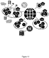
- Figure 2 shows an alternative arrangement in which the role of the central system is replicated so that the same functions are performed by a distributed set of nodes, each with the capability to perform some or all of the functions provided by the central system.
- Individual nodes should see a significantly lower demand than the central system, and as entities should be able to interact with a more local node than the central system, there is potential to reduce network latency.
- there are significant technical challenges in achieving this benefit - in particular, there would for straightforward replication be a need to distribute all the same information to all the nodes replicating the centralized system, generally making the overall position worse rather than better.
- the product of the first service performed by the first user is valuable information - such as the proof of a payment made by the first user to be used by a second user in completing a transaction - then risks of system failure or compromise by, for example, use of a proof at multiple nodes by multiple second users to complete a relevant transaction, need to be addressed.
- a first user 1 requests execution of a first service 3 - in this case, the creation of a proof of an event such as a payment from a particular account - and a second user 2 requests verification of the proof of this event, for example to determine that a payment is validly made, from a second service 4.
- the first user 1 has invoked the first service 3 at a first node 5.
- the second user will typically not have a choice of where to invoke the second service 4 - this may be a matter of geography or other administrative factors - and in particular may not be able to invoke the second service 4 at the first node 5 (though this may be a possibility).
- the second service 4 will be invoked at a further node 6a, 6b, 6c that has sufficient information to achieve the verification process.
- this will involve access to a common set of cryptographic keys together with the minimal set of information required to regenerate the proof or otherwise determine that the proof is correct - as discussed below, in embodiments a limited set of keys may be used.
- Situations in which such a proof, or an object claiming to be such a proof, is presented to one or more second services at one or more nodes need to be addressed for such a system to function reliably and securely.
- FIG. 4 A system of monitoring according to embodiments of the disclosure is shown in Figure 4 , which extends the arrangement of Figure 3 by inclusion of a monitoring system.
- each service in a node such as first service 3 and second service 4
- has an associated monitoring service such as first service monitoring service 31 and second service monitoring service 41
- first service monitoring service 31 and second service monitoring service 41 that interacts directly with its associated service using suitable messaging, performing monitoring at the time that the service is performed and providing information, including information received from elsewhere in the distributed system, that is needed by the associated service for correct current or future service delivery.
- Each monitoring service has at least two further communication paths.
- One is a peer to peer (horizontal) communication path 7 for communicating with monitoring services in other nodes using inter-node messages so that information immediately identifiable as relevant to other services are transmitted to the monitoring services for those services.
- this peer to peer (horizontal) communication path is shown as an inter-node path, it can effectively also operate within a single node if multiple services are provided within that node (i.e., if processes 4 and 41 would run in node 5 next to the processes 3 and 31) - in this case the peer to peer (horizontal) communication path between 41 and 31 is provided as an intra-node message or path.
- intra-node and in-node may be used interchangeably here to refer to a message sent within the same physical or logical node, though the term in-node will be used generally below.
- This pathway is particularly effective for direct communication between monitoring services for a second service verifying a proof and a first service that has created the proof.
- the second communication path is a path 8 between each local monitoring service 31, 41 and a coordinated monitoring service - which may be provided as a central monitoring service 9, for example.
- a coordinated monitoring service - which may be provided as a central monitoring service 9, for example.
- This is useful to support an escalation process for evaluating potential errors or threats that are not determinable directly by a local monitoring service, and for communicating actions to affected nodes, or services in nodes, when such issues have been detected when a distributed reaction is required in order to address the threat and mitigate the associated residual security risk.
- the arrangement shown here has a third communication path used for vertical communication between the services 3, 4 and their monitoring processes 31, 41. This is here used for messaging between the service 3, 4 and its monitoring process 31, 41 for monitoring of service expected operation. In the arrangements described here, messaging is used for this purpose, though in other architectures it is conceivable that monitoring may be achieved by measurement without an explicit messaging step. However, this third communication path is also valuable for provision of information back to the service 3, 4 from the monitoring process 31, 41
- This architecture is effective to allow both the first service and the second service to take place without delay while allowing effective monitoring using peer-to-peer interaction between monitoring processes to exchange a first type of information and a remote coordinated monitoring system to receive a second type of information.
- the first type of information can be used to provide rapid updates that can address, for example, coordinated attacks, whereas the second type of information can be used to ensure sufficient knowledge of events across the system to prevent other types of attack developing.
- This approach supports effective monitoring across the distributed system, but with information exchanges limited to those necessary to maintain an effective and secure system.
- the timing of messaging within the extended system is highly significant. There are three timing types used for messaging: real time; near real time; and post-service.
- Real time messaging is immediate. Near real time messaging may not be immediate - real time messaging is prioritised over it - but it is rapid and may complete during a related extended system event, and such that monitoring information may be received during use of multiple second services in parallel.
- Post-transaction messaging is less urgent and is used for reconciliation and system changes to remove identified vulnerabilities.
- messaging and processing involved in provision of services to users takes place in real time, enabling such services to be full real time processes.
- Local monitoring and associated communication such as messaging peer to peer between monitoring services take place typically in near real time, so the speed of service provision is not affected but so that response is sufficiently rapid to address threats on a sufficiently short timescale.
- near real time communication is sufficiently rapid that it will take place in the same time frame as the associated broader process in which the second service is used, and often before the completion of such a process, rendering this approach effective against attacks or problems occurring at multiple points in the system.
- Coordinated monitoring and other communications involving the coordinated monitoring service typically do not need to be immediate and can be carried out after the completion of the associated service. This approach therefore allows for effective response to threats in a distributed system of service provision without compromising the operation of service provision itself.
- Figure 5 is a block diagram of a typical four-party model or four-party payment transaction scheme. The diagram illustrates the entities present in the model and the interactions occurring between entities operating in a card scheme.
- card schemes - payment networks linked to payment cards - are based on one of two models: a three-party model or a four-party model (adopted by the present applicant).
- a three-party model or a four-party model (adopted by the present applicant).
- the four-party model is described in further detail below.
- the four-party model may be used as a basis for the transaction network.
- the model comprises four entity types: cardholder 110, merchant 120, issuer 130 and acquirer 140.
- the cardholder 110 purchases goods or services from the merchant 120.
- the issuer 130 is the bank or any other financial institution that issued the card to the cardholder 110.
- the acquirer 140 provides services for card processing to the merchant 120.
- the model also comprises a central switch 150 - interactions between the issuer 130 and the acquirer 140 are routed via the switch 150.
- the switch 150 enables a merchant 120 associated with one particular bank acquirer 140 to accept payment transactions from a cardholder 110 associated with a different bank issuer 130.
- a typical transaction between the entities in the four-party model can be divided into two main stages: authorisation and settlement.
- the cardholder 110 initiates a purchase of a good or service from the merchant 120 using their card. Details of the card and the transaction are sent to the issuer 130 via the acquirer 140 and the switch 150 to authorise the transaction.
- the cardholder 110 may have provided verification information in the transaction, and in some circumstances may be required to undergo an additional verification process to verify their identity (such as 3-D Secure in the case of an online transaction). Once the additional verification process is complete the transaction is authorised.
- the transaction details are submitted by the merchant 120 to the acquirer 140 for settlement.
- the transaction details are then routed to the relevant issuer 130 by the acquirer 140 via the switch 150.
- the issuer 130 Upon receipt of these transaction details, the issuer 130 provides the settlement funds to the switch 150, which in turn forwards these funds to the merchant 120 via the acquirer 140.
- the issuer 130 and the cardholder 110 settle the payment amount between them.
- a service fee is paid to the acquirer 140 by the merchant 120 for each transaction, and an interchange fee is paid to the issuer 130 by the acquirer 140 in return for the settlement of funds.
- the roles of a specific party may involve multiple elements acting together. This is typically the case in implementations that have developed beyond a contact-based interaction between a customer card and a merchant terminal to digital implementations using proxy or virtual cards on user computing devices such as a smart phone.
- Figure 6 shows an architecture according to an embodiment of the disclosure appropriate for interaction between a cardholder and a merchant.
- This Figure shows a general-purpose architecture for reference but shows in particular elements of an architecture used when a cardholder carries out an online transaction with a merchant server.
- a cardholder will use their payment card 6 - or a mobile computing device such as smartphone 11 adapted for use as a contactless payment device - to transact with a POS terminal 7 of a merchant 2.
- the cardholder will use his or her computing device - which may be any or all of a cellular telephone handset, a tablet, a laptop, a static personal computer or any other suitable computing device (here cellular telephone handset or smartphone 11 is shown) - and other computing devices such as a smart watch or other wearable device may also be used) - to act either as a proxy for a physical payment card 6 or as a virtual payment card operating only in a digital domain.
- the smartphone 11 may achieve this with a mobile payment application and a digital wallet, as described below.
- the smart phone 11 can use this to transact with a merchant POS terminal 7 using NFC or another contactless technology, or to make a payment in association with its wallet service as discussed below.
- online transactions with a merchant are of particular interest in connection with embodiments of the disclosure, rather than contact or contactless transactions with a merchant POS terminal 7.
- the smartphone 11 may also be able to interact with a merchant server 12 representing the merchant 2 over any appropriate network connection, such as the public internet - the connection to the merchant may be provided by an app or application on the computing device.
- the transaction scheme infrastructure (transaction infrastructure) 5 here provides not only the computing infrastructure necessary to operate the card scheme and provide routing of transactions and other messaging to parties such as the acquirer 3 and the issuer 4, but also a wallet service 17 to support a digital wallet on the cardholder computing device, and an internet gateway 18 to accept internet based transactions for processing by the transaction infrastructure.
- the wallet service 17 may be provided similarly by a third party with an appropriate trust relationship with the transaction scheme provider.
- a token service provider 19 is present (again, this is shown as part of transaction infrastructure 5 but may be provided by a third party with appropriate trust relationships), and the transaction scheme infrastructure provides a digital enablement service 16 to support the performance of tokenised digital transactions, and to interact with other elements of the system to allow transactions to be performed correctly - this digital enablement service may include other elements, such as token service provision.
- the transaction is validated in the transaction scheme by mapping the cardholder token to their card PAN, checking the status of the token (to ensure that it is in date and otherwise valid) and any customer verification approach used. This allows the issuer to authorise the transaction in the normal manner.
- FIG. 7 shows elements of a transaction infrastructure to support digitised payments from a mobile device in more detail.
- This Figure shows as a specific example the applicant's Mastercard CloudBased Payment (MCBP) architecture - this is exemplary rather than specific to the disclosure, and illustrates how the architecture is used to support a mobile payment application 215 on a mobile device (such as smartphone 11) - here the mobile payment application 215 is shown as contained within a wallet application or digital wallet 41.
- a digital wallet 41 may communicate with a wallet server 17 to allow management of the mobile payment application, and it also can be used to request digitization of a payment card 6 to be used by the mobile device 11.
- the Mastercard Digital Enablement Service (MDES) 42 performs a variety of functions to support mobile payments and digitized transactions. As indicated above, the MDES 42 is exemplary only - other embodiments may use digitisation, tokenisation and provisioning services associated with other transaction processing infrastructures, for example.
- the wallet server 17 is not a part of the MDES 42 - and need not be present, for example if the mobile payment application 215 is not embedded within a digital wallet 41 - but acts as an interface between the mobile device 11 and the MDES 42.
- the MDES 42 also mediates tokenised transactions so that they can be processed through the transaction scheme as for conventional card transactions.
- the following functional elements shown within the MDES 42 the Account Enablement System (AES) 43, the Credentials Management System (CMS) 44, the Token Vault 45, and the Transaction Management System (TMS) 46. These will be described briefly below.
- the Account Enablement System (AES) 43 is used in card digitisation and user establishment. It will interact with the mobile payment application (here through the wallet server 17) for card digitisation requests, and it will populate the Token Vault 45 on tokenisation and will interact with the CMS 44 to establish a card profile with associated keys for digital use of the card.
- AES Account Enablement System
- the Credentials Management System (CMS) 44 supports management of cardholder credentials and is a key system within the MDES 42.
- the core system 441 manages synchronisation with the transaction system as a whole through interaction with the TMS 46 and manages the channel to the AES 43.
- the dedicated system 442 provides delivery of necessary elements to the mobile payment application such as the digitized card and credentials and keys in the form needed for use. This system may also interact with the wallet server 17 for management of the mobile payment application.
- the Token Vault 45 - which is shown here as within the MDES 42, but which may be a separate element under separate control - is the repository for token information including the correspondence between a token and the associated card.
- the MDES 42 will reference the Token Vault 45, and tokenisation of a card will result in creation of a new entry in the Token Vault 45.
- TMS 46 Transaction Management System 46 is used when processing tokenised transactions. If a transaction is identified by the transaction scheme as being tokenised, it is routed to the TMS 46 which detokenises the transaction by using the Token Vault 45. The detokenised transaction is then routed to the issuer (here represented by Financial Authorisation System 47) for authorisation in the conventional manner.
- the TMS 46 also interacts with the CMS 44 to ensure synchronisation in relation to the cardholder account and credentials.
- Embodiments of the disclosure are directed to enabling aspects of a system for the performance of a digitized transaction as shown in Figure 7 - and in particular the management of credentials - to be decentralized. This is done by replacing a central node with a decentralized set of nodes each capable of credential management, as is shown in Figures 8 to 10 .
- Figure 8 shows a decentralised system of computing nodes Nx, each capable of both generating G and validating V credentials. These credentials can be valid across the whole system (unless restricted to some nodes as result of on-soil regulation or the like), and in this case are associated with transactions for a set of users (clients) whose transactions are routed to that node, typically through geographic proximity. Nodes provide credential generation G and credential validation V as services to clients, and they need to be able to generate the credentials securely and validate them securely while they are valid at least. In the architecture shown, credentials are not stored - they are generated on request and validated on the fly.
- key management K and monitoring M can be considered as services both locally at a node and across the system, and access control AC will typically be required to allow access to a service.
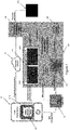
- the node 80 comprises at least one networking connection 81 to allow communication to clients 90 and other nodes 91 as well as (in this example) a central node 91a. Communication is shown here as being through separate networks to each set of other parties - through a first network cloud 92 for connection to clients, and a second network cloud 92a for connection to other nodes within the distributed system. This reflects that these networks may be physically different, or that they may have different security requirements and protocols.
- the node 80 contains a plurality of conventional servers 83 (which will contain their own processors and memories - not shown - along with other components as would normally be found in a server) and a memory 84 containing a central database. Also comprised within the node 80 are a plurality of hardware security modules 85 (HSMs), adapted to hold cryptographic material in the form of keys needed to perform cryptographic functions and to perform cryptographic functions securely. Here elements within the node 80 are shown communicating by means of a bus 86.
- HSMs hardware security modules
- the node 80 in this case is represented as a single data centre, this is not required - the "bus" may be, for example, comprise a dedicated network connection between a group of related data centres that allows them to provide a real-time response such that they will appear to other entities communicating with the node to be part of an integrated whole.
- credentials are generated using keys derived according to a hierarchical process. Issuer Master Keys (IMK) are associated with a specific range of tokens, and keys for use for credentials are derived hierarchically (Card Master Keys - CMK - from IMK, and then Session Keys - SK - from CMK).
- IMK Issuer Master Keys
- CMK Card Master Keys
- Session Keys - SK - from CMK Session Keys
- This approach is used for devices, such as physical cards, but is also used for digital transactions. The number of digital transactions is increasing extremely rapidly, as opposed to device-based interactions where the growth is more consistent with resources.
- This distributed approach is supported by replacing the binding of a token to a specific hierarchically derived key, allowing instead the first available key from a stack of keys to be allocated to a tokenized transaction.
- This approach using flexible and dynamic key management, allows for a scalable solution. Monitoring can be carried out in such a way as to ensure that the distributed architecture is secure without requiring the transmission or replication of large quantities of sensitive information.
- This approach can also be carried out in a standard HSM using fully FIPS compliant processes - for example, DES and 3DES need not be used. This approach is described in more detail below.
- the device security model is also used by the present applicant for fully digital transactions.
- This security model involves Issuer Master Keys (IMKs) being stored in the transaction system HSMs and used to derive Card Master Keys (CMKs) from the relevant IMK and a card PAN (Primary Account Number). These CMKs are then stored in a device (typically a Secure Element or substitute technology).
- IMKs Issuer Master Keys
- CMKs Card Master Keys
- PAN Primary Account Number
- CMKs Card Master Keys
- SK Session Key
- ATC Application Transaction Counter
- CMS Credentials Management System
- the main purpose of the cryptographic function is to provide a guarantee - this covers both integrity of the data and authentication.
- the transaction related data protected by a cryptographic data includes identification of a transaction and the associated token, along with an indication of any cryptographic processes used and any relevant financial data (along with any other aspect of the transaction that needs to be guaranteed).
- This is represented by a transaction credential - this needs to be generated G and subsequently validated V, with these processes being monitored M to ensure overall system integrity and supported by a key management system K of some kind.
- the present disclosure relates to an approach to monitoring which is effective to address the consequences of erroneous or malicious action by appropriate detection, messaging and reaction - as will be described, this largely takes place separately from the actual performance of a transaction.
- This approach allows for decentralisation of the credential system from a complex central server into a number of nodes providing services.
- These nodes will typically be geographically distributed but may extend over a number of data centres (for example, by use of a cloud infrastructure to achieve data sharing within a node).
- These nodes provide services - in relation to credentials, a generation service G and a validation service V - with defined rules for access control to the services.
- the merchant or PSP communicates with the generation service G to obtain credentials, which are then used in a standard authorisation process carried out over the payment network of the payment system, with the validating service V being called upon where necessary to validate the credential.
- These services have access to the computing infrastructure (HSMs, databases) of a node.
- Monitoring M and key management K services are also provided - these may be centrally organised or comprise a mix of central and local functionality.
- Access control to services can be provided in an essentially conventional manner.
- a general set of controls can be defined for a node, with the possibility of local modification - for example, to meet local regulatory or other specific security requirements. This approach makes it easy to implement localised policies, for example, by constraining all traffic for a particular country to a particular set of nodes, or by taking other region- or market-specific actions.
- Access control can be performed at more than one level (for example, for individual services, but also for a node), and there may be specific rules or checks for specific service types.
- Access control is potentially very granular and may provide specific solutions in a versatile way - for example, it could be used to allow a given merchant to perform a maximum number of transaction credential generation operations during a defined time for a given token.
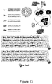
- the key management mechanism shown in Figure 13 illustrates how a limited number of keys can be allocated to a node while providing a deterministic process in order to pick a key to generate credentials. The same process can be used by a validation entity to determine the key that was used by the generator so that it can validate any cryptographic material that is part of the credentials submitted for validation.
- the HSMs contain keys that are each uniquely identified by a set of key identifiers (Keyld).
- Keyld may be a label, a value, an explicitly unique value such as a UUID, or anything else with appropriate properties.
- These Keylds are stored in uniquely identified (Identifier) key lists - these key lists provide a list of relationships between an identifier (Id) and a stored key (Keyld).
- the identifiers (Id) are what will be determined by the deterministic process in order to establish what key is to be used, as will be described further below.
- each key list is guaranteed using a seal (Seal) - if the key lists are provisioned from a central location, this may be applied by a trusted party associated with that central location.
- a trusted party being a local functionality instead of a central location.
- a node will typically have a number of key lists available, but with only one active for generating credentials (G) at a given time - it will however generally be necessary for the validation service (V) to be able to access any key list that may be associated with a credential that is still valid. Key rotation in this approach is extremely straightforward - it may simply involve replacement of the active key list with another key list.
- Figure 13 illustrates an exemplary arrangement for Node Ni, which has two generation services G able to generate credentials associated with transactions.
- these services G will be required to use a given key list - say Key List A in the first instance.
- This uses the yellow and blue keys, so these keys must be loaded in the HSMs used by the generation services G.
- the key rotation process may for example mandate the use of Key List B - this uses yellow and blue keys, but also the green key, so the green key must be loaded in the relevant HSMs if not already present.
- the generation services G do not need Key List A after key rotation, the validation services V still do - they require access to any key list that relates to a potentially valid credential.
- the validation services V must be able to establish exactly which key was used to generate a credential by the generation services G in order to validate a credential.
- the transaction related data to be protected cryptographically includes identification of the token associated with the transaction, but also identification of the transaction itself. For this, some kind of transaction identifier is required.
- the credential generation and validation services have access to a local database which can be used to manage such data.
- any generation of transaction credentials for a given token should be associated with a unique transaction identifier for each transaction. This may be a UUID or any appropriate identifier structure (such as a concatenation of an n bit node identifier, an e bit epoch time, and a c bit local counter).
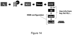
- the size of data to be carried in transaction credentials could however be reduced to a few digits by use of a local transaction counter. This could simply be stored in the local database of a node and the local (rather than a global) value incremented when a local generation service G generates new transaction credentials for a token, a process shown in general terms in Figure 14 .
- a generation service G has access to a set of keys in local HSMs and uses keys in accordance with its currently active key list.
- This key list is itself uniquely identified (by Identifier ) and contains a list of entries which correspond to relationships between an identifier ( Id ) and a stored key, represented by KeyId.
- Id an identifier
- KeyId a stored key
- LTC local transaction counter
- Id LTC MOD 10
- Any validation service V with access to the transaction counter value in transaction data can then determine the logical key identifier that was used by the generation service G that generated the credential and access the correct stored key without any trial and error mechanism.
- Associating the deterministic process function (referred to below as keyList.GetldFunction) to the attributes of a key list in this way allows a scalable solution that can accept any number of logical key identifiers for a given key list.
- the HSM cryptographic function should be appropriate to ensure data integrity and authentication through credential generation and validation.
- the cryptographic function operates on the chosen transaction data, using the key, and provides an output which does not expose the key.
- Various alternative cryptographic functions could be used - HMAC is a particularly effective choice with several options regarding the hashing function, but CMAC, CBC MAC are among possible alternatives not even talking about solutions using asymmetric cryptography.
- the cryptographic function used should be specified in the key list (as keyList.CryptoFunction ) and is also driven by the capabilities of the HSMs used for generation and validation. On-soil regulations, cryptographic material export or other security considerations may lead to the choice of specific cryptographic functions.
- Legacy transaction use cases provide a solution when the Merchant and/or the PSP are only able to manage PAN, Expiry Date and CVC2 as part of the transaction flow, and do not have access to more recent developments.
- the UCAF use case aims to leverage the more recently introduced Universal Cardholder Authentication Field to carry more data as part of the transaction flow.
- the DPD use case covers the introduction of Digital Payment Data, a container able to carry all the data needed as part of the transaction flow.
- FIG. 15 A full set of cryptographic mechanisms is shown in Figure 15 .
- Key management is discussed with reference to Figure 16 .
- the key lists are sensitive assets while keys are considered as secret assets - the key lists define the keys to be used for generation and validation of cryptograms. Keys require end to end security with secure transport of the keys using wrapping/unwrapping techniques when loading the keys in HSMs. Their use should not be compromised by the key lists in case an attacker would like to change the content of a key list in order to alter the key selection process.
- a seal is provided for a key list by the generating party or an associated trusted party, will involve a suitable cryptographic process (such as HMAC with an appropriate dedicated key or using for example a digital signature generated using asymmetric algorithms such as RSA, ECC, SM27), and has the effect that any relevant part of the system can have confidence that the key list was generated by an appropriate party and has not been modified.
- the key list seals can be used in the generation and validation of cryptograms to secure the credentials.
- Monitoring is shown in general terms in Figure 17
- monitoring is complementary to security actions taken directly in a service to prevent fraud or misuse (such as the basic purpose of the service - generation of a credential using a cryptogram with subsequent verification).
- Such monitoring aims to detect security anomalies associated with a transaction - it can then trigger appropriate reaction mechanisms to contain any security risk and identify any attacker. In principle, this may have both local and central aspects. It is found that a hybrid approach is particularly effective in order both to provide effective detection of any issue and to produce reaction effective to counter risks associated with a fully distributed architecture.
- a monitoring architecture will now be described with reference to Figures 18 and 19 , with interactions between system elements described in later sections.
- the description defines system elements and their actions such that the skilled person will be able to implement them, without unnecessary constraints on messaging or information storage - it provides a full description of the functional needs and core principles related to monitoring according to embodiments of the disclosure.
- G1, V2... means "G in node 1, V in node 2"
- Vj the validation process in node Nj
- Vk the validation process in node Nk.
- Any G, mG, V, mV... can have several instances for a given node. This applies to M, or any other entity.
- audit activities in order to guarantee the integrity of the system should be considered - these will cover among others access control, the communication layers between the entities involved and the management of HSMs (Hardware Security Modules).
- HSMs Hard Security Modules
- Figure 18 shows a monitoring architecture used in embodiments of the disclosure.
- the conventional transaction system elements engaging with the process of generation and validating credentials for a transaction - the merchant (or payment service provider in the case of online transactions) 161, the acquirer 162 and the transaction scheme provider 163.
- the next level relates to the distributed nodes, and it relates to the basic processes of the node 164 - generation services G 165 and validation services V 166 - here, multiple validation services are shown, indicating that the credentials generated by a generation service G may be validated by a variety of validation services Vj, Vk.
- node 164 contains only a generation service and the validation services are in other nodes (not explicitly identified).
- An alternative node (164a) is also shown in shading as an alternative possibility - in this case there is both a generation service G and a validation service V in the same node.
- a generation service G has access to a local database 1651 and a validation service has access to a local database 1661.
- Also within the node 164 are local monitoring services mG 167 with local database 1671 for monitoring generation services 165 and local monitoring services mV 168 with local database 1681 for monitoring validation services 166.
- there are interactions and messaging between local monitoring services and the services that they are monitoring, but also between services - here, messaging (typically internode messaging) between local generation service monitoring mG and local validation service monitoring mV is shown.
- a further level is needed if the global monitoring service M 169 is required - typically this is the result of some kind of escalation.
- the global monitoring service 169 is able to communicate with both types of local monitoring service 167, 168. If an action needs to be cascaded to each node (represented as a distributed action in Figure 18 ), messages may originate from the global monitoring service M and be cascaded to each generation service G and validation service V through their local monitoring services mG and mV.
- this architecture is a specific example of a more general architecture for monitoring of service processes that may be carried out in one of a number of nodes of a distributed computing system.
- this architecture is effective to allow the service process - in this specific architecture, both the credential generation process and the credential validation process are service processes, each carried out for a client - to take place without delay while allowing effective monitoring using peer-to-peer interaction between monitoring processes to exchange a first type of information and a remote coordinated monitoring system to receive a second type of information.
- the first type of information can be used to provide rapid updates that can address, for example, coordinated attacks, whereas the second type of information can be used to ensure sufficient knowledge of events across the system to prevent other types of attack developing.
- FIG 17 shows this arrangement with the levels explicitly marked.
- the top level 171 involves only conventional transaction scheme entities.
- the second level 172 and the third level both exist within nodes - the second level 172 is a service layer and the third level 173 is a monitoring layer.
- the fourth layer 174 is constituted by the global monitoring service and messaging associated with this service.
- Key management is explicitly not shown in Figures 18 and 19 , but the principles underlying key management are provided here for completeness. Monitoring of key management activities is considered as a specific process associated with system audit. Key management monitoring provides assurance that cryptographic materials are ready to be used, and that they are properly wiped or archived (using escrow services) when no longer required to support transaction credentials generation and validation. Key management monitoring also addresses the management of key lists through creation, distribution, activation and deactivation.
- both local monitoring (mG and mV) and central or coordinated monitoring (M) will be aware of key management activity but will be separate from key management monitoring.
- the local monitoring processes will not access the HSMs containing transaction keys, and so these processes will not be able to call on HSM cryptographic processes (and so will not be able to generate or validate credentials on an ad hoc basis).
- Coordinated monitoring M may in embodiments be able to do this, preferably through specific interfaces determined by the key management process.
- a validation process V operating in node Nj can validate transaction credentials from a given set of generation processes G operating in that node and other nodes ⁇ Ni, Nj, Nk... ⁇ .
- each generation process G - from which transaction credentials can be validated by a validation process V - has an associated key list (KLi, KLs, KLref%) which is shared with validation processes V where KLi is the key list identifier, KLs is the key list seal and KLref is the key list reference.
- Figure 18 shows the same interactions for mVk, located in node Nk.
- This peer to peer communication between monitoring processes allows rapid communication of significant information between monitoring processes (and so between associated service processes through the vertical communication between monitoring processes and service processes) without impacting the services themselves, as will be described further below.
- Any local monitoring process mG/mV can interact with a coordinated monitoring process M.
- This coordinated monitoring process M is typically not directly linked to a node, but rather bridges between the local monitoring processes of multiple nodes. It also provides an eventual reaction manager which can be used to target one, several or all the nodes to make necessary changes (for example, to adapt the system to respond to a known threat).
- Such monitoring processes may need to store for a while some sensitive data such as cryptograms or input for transaction credentials generation and/or validation.
- Credential generation and validation services can communicate with associated monitoring processes (mG/mV) within the same node using a pair of vertical in-node messages as follows:
- the two local monitoring processes mV and mG within the same node can communicate with each other using a pair of horizontal in-node messages as follows:
- Two local monitoring processes mV and mG situated in two different nodes may communicate with inter-node messages, namely:
- a local monitoring generation process (mG) or a local monitoring validation process (mV) in any node may call the coordinated monitoring process (M) through an Escalation message.
- M can trigger Distributed Action message(s) to one or more local monitoring processes (mG/mV) in any node to make the system fully aware of a necessary change.
- Timing of messaging within the extended system is highly significant within the system described.
- Real time messaging is immediate. Near real time messaging may not be immediate - real time messaging is prioritised over it - but it is rapid and will typically complete during a related extended system event, such as the authorisation of a transaction.
- Post-transaction messaging is less urgent and is used for reconciliation and system changes to remove identified vulnerabilities.
- the timing used for specific messages is as follows:
- messaging between, within and from the first and second layers are generally sent in real time, enabling generation and validation to be full real time processes.
- Local monitoring and other communication within the third layer take place typically near real time, so the speed of transactions is not affected but so that response is sufficiently rapid to address threats on a sufficiently short timescale.
- near real time communication is sufficiently rapid that it will take place in the same time frame as the associated transaction system process - here, this will typically be authorisation of a transaction - often before the completion of such a process, rendering this approach effective against attacks or problems occurring at multiple points in the system.
- Coordinated monitoring and other communications involving the fourth layer do not need to be immediate and can be carried out post-transaction.
- the main transaction system events are that G performs cryptogram generation as payment proof of a transaction. G then delivers transaction credentials to the party that has requested them (merchant or PSP). These transaction credentials are provided to V as part of the transaction flow (received over the payment network from the acquirer). V will validate the cryptogram and decide whether it validates the transaction credentials or not. These actions may be embedded in other layers of transactional activity, but these are not relevant to the present disclosure.
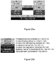
- FIGS 20a and 20b - are complementary to the main service flows based on cryptogram generation/verification as described above.
- Figure 18a illustrates actions with vertical flows within a processing node (and to the node's client and the coordinated monitoring service) and horizontal flows between processing nodes
- Figure 18b provides a key to the types of action shown.
- the monitoring flow is based on the detection of a security anomaly and the triggering of appropriate actions with vertical flows within a processing node (and to the node's client and the coordinated monitoring service) and horizontal flows between the processing nodes for anomaly Reporting and a security-maintaining Reaction to it.
- vertical processes include Monitoring (by the monitoring service associated with a generation or validation service) and Escalation to the coordinated monitoring service M which may provide Distributed Actions to multiple nodes, with individual services responding to these by provision of Actions from the monitoring service to its associated service.
- inter-service which may be in-node or inter-node
- inter-service Reaction which may be in response to Reporting
- G and V are also involved in a complementary monitoring process to increase the trust in the decision of the distributed system.
- the processing and messaging provided by the validation services V1 and V2 is exactly as provided by the validation service V in the original example.
- the process at the monitoring generation service mG will be subtly different from before.
- mG needs to consolidate responses from non-interacting monitoring validation services mV1 and mV2.
- An effect of this consolidation in particular in relation to reporting of the ranges of pseudo-random numbers (P') seen by each validating entity V1 and V2, is to allow mG to determine whether any of these pseudo-random numbers has been used by more than one validator, which is an indication of potential fraud.
- Such a detection could be escalated to the coordinated monitoring service M and Distributed Action messages could be sent to mG, mV1 and mV2 to allow a determination of how processing should be stopped or controlled to prevent potential fraud.
- the next complex use case involves two generation services G1 and G2 and a single validation service V validating transaction credentials from both generation services.
- the two generation services G1 and G2 do not communicate with each other, and each uses a different key list.
- V must therefore have knowledge of both key lists and use the appropriate key list depending on the generation service that generated a given credential.
- both mG1 and mG2 will act exactly as the generation monitoring service mG in the original example.
- the monitoring situation for the validation service is different, however.
- Validation monitoring service mV must be able to send both in-node and inter-node Reporting messages to each relevant generation monitoring service, and also receive Reaction messages from both generation monitoring services. Since G1 and G2 are using different key lists, the transaction credential generation action performed by one G (G1 or G2) is completely independent of the transaction credential generation action performed by the other G, and as a result their corresponding lists of pseudo-random numbers (P') and local transaction counters (LTC) are completely independent of each other.
- P' pseudo-random numbers
- LTC local transaction counters
- the coordinated monitoring service M can instruct a Distributed Action to both mG1 and mG2 if a malicious behaviour identified in a transaction with credentials generated by one service and validated by V may have consequences for validation by V of credentials generated by the other generation service.
- This is a practical concern, since an attacker that succeeded in an attack relating to a particular card or token (PAN/TUR) in, say, a (V ⁇ -> G1) interaction would be likely to use it for a (V ⁇ -> G2) interaction as well.
- Use of M is effective to stop malicious processing affecting both generation services (G1 and G2) in a case where one of them was compromised.
- a basic principle here is to separate the monitoring flows from the transaction flows as much as possible, with mG and mV providing the only points of interaction with their associated services in relation to monitoring, both for making monitoring actions that are processed in flows entirely separated from the transaction flow, and for communicating necessary actions to the associated service from other nodes or from the coordinated monitoring service M.
- Figure 21a shows the interaction flow for the generation service G, with the broader generation process considered to extend across actual credential generation by G followed by G sending a vertically down in-node monitoring message (G -> mG) with the result of the cryptographic service activity and a complete trace of execution to its local generation monitoring (mG) process.
- mG stores this trace - including transaction related information - and updates the status in its databases.
- mG also processes this information, and this may trigger two different vertical interactions.
- Figure 21b shows the interaction flow for the validation service V validating a credential generated by the generation service G.
- the monitoring actions do not disturb the transaction flow - the validation action takes place first, followed by sending a vertically down in-node monitoring message (V -> mV) to its local monitoring validation (mV) process.
- V -> mV vertically down in-node monitoring message
- mV local monitoring validation
- This information relates to cryptographic validation and LTC management - other checks may be made during the validation process, but these are not directly relevant to this disclosure and are not discussed further here.
- the processing performed by mV may result in three different interaction streams:
- Generation service monitoring mG receives an in-node or inter-node Reporting message, and processes the information received and evaluates risk. Three further interaction streams may result, with communication with the following system elements:
- an escalation process is performed by coordinated monitoring service M. This may result in three further interaction streams, involving M sending Distributed Action messages to:
- the local monitoring processes perform their analysis and may determine three further interaction streams, sending in-node action messages to G only, to V only, or to both - this flow is shown in Figure 21c .
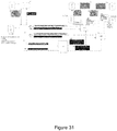
- Figure 22 presents the transaction and monitoring flow for a successfully completed transaction credentials generation service action requested by a legitimate merchant (or PSP). This case covers an entirely vertical flow between G and mG without any escalation to the coordinated monitoring process M.
- Credential generation actions are as follows:
- monitoring actions take place in near real time, after the generation service G has provided credentials, and monitoring actions are as follows:
- Figure 23 presents the transaction and monitoring flow for a successfully completed transaction credentials validation service action requested by a legitimate merchant (or PSP). This case covers an entirely vertical flow between V and mV without any escalation to the coordinated monitoring process M.
- Real time validation actions are as follows:
- validation monitoring takes place after a validation result has been returned, and the following steps take place in near real time:
- Figure 24 shows a monitoring flow detecting a replay attack (attempted resubmission of credentials that have already been validated). This can lead to suspension of access for a merchant or PSP to the transaction credentials generation service.
- the relevant initialization state of the flow is as follows:
- Figure 25 shows a monitoring flow that prevents a replay attack involving multiple nodes, here termed a double-spending attack. This is prevented by a post-transaction action flow running in near real-time that prevents the double spending of a valid payment message in the following two cases: multi-acquirer merchant (or PSP) attack; and merchant (or PSP) attack on a multi-node acquirer.
- multi-acquirer merchant (or PSP) attack and merchant (or PSP) attack on a multi-node acquirer.
- the attacker is hoping that two or more transactions performed with the same payment message may be authorised as the same valid payment message will be treated in multiple nodes and that their databases (particularly VLTC DB) may not be effectively synchronised:
- the monitoring process has enabled the system to identify not only replay attacks at a single node but also replay attacks involving multiple nodes.
- the reaction flows then vary depending on the situation as follows.
- reaction flow to be performed when a double-spending attack (replay attack with multiple nodes) is detected is provided below for the following two cases:
- mVk the primary objective of mVk is to notify G so that the merchant (or PSP) can be blacklisted so it will stop generating transaction credentials that can be misused. This decision to block could be taken when the first replay is detected, or when the number of replays exceeds a limit defined in the associated key list.
- mVk may also escalate the detected issue to the coordinated monitoring M.
- the objective would be for M to distribute the information to all mVs (and associated Vs using in-node messaging) if this is necessary to stop the validation of all transaction credentials that are part of transactions coming from that MID - this is not explicitly shown in Figure 26 .
- the same approach could be taken to communicate to a list of mGs (to cascade to the relevant Gs) where the merchant (or PSP) is using more than one node for the generation of transaction credentials.
- Figure 27 indicates the use of the monitoring system to detect and communicate replay fraud between an associated G and V - this is here a replay attack attempted by a merchant (or PSP) on a single node Vj validating transaction credentials generated by G.
- Figures 28 to 30 relate to the use of the monitoring system to detect and signal different types of guessing attacks.
- Figure 28 relates to the situation where there is no malicious intent, but only a processing error introduced by the acceptance infrastructure;
- Figure 29 relates to a guessing attempt made by a single Merchant (or PSP);
- Figure 30 relates to a guessing attempt made by a coalition of dishonest Merchants (or PSPs).
- FIG. 29 shows a monitoring and signalling flow where the Merchant is malicious, rather than facing an infrastructure fault.
- This monitoring flow is intended to contain the threat of a merchant (or PSP) introducing false transactions in the system. For these transactions:
- the Figure 30 case shows monitoring in the case of a guessing attempt by a coalition of dishonest Merchants (or PSPs).
- this monitoring scenario we try to spot a collusion of two (or more) dishonest merchants (or PSPs).
- This allows attempts to continue in search of a correct guess without suspension of Merchant access to the transaction credentials validation service (as part of the processing of transactions) which may be combined with a suspension of their access to the transaction credentials generation service.
- Figure 31 shows a further monitoring process to be carried out at the end of a period of validity for a particular key list. This allows statistics relating to the transaction credentials generated and validated for a (or a list of) PAN/TUR at the end of a key list validity period to be assessed.
- the objective is to identify any discrepancy with the counters (generation [CtrTrxG] vs. validation [CtrTrxVj, CtrTrxVk...]) that may reveal some attempts to misuse the system.
- the embodiments described above are exemplary, and further embodiments falling within the spirit and scope of the disclosure may be developed by the skilled person working from the principles and examples set out above.
- the embodiments described in detail above relate particularly to the generation and validation of credentials used in financial transactions. Generation and validation of credentials in this way is not limited to financial transactions - this approach may be used in any distributed system where it is necessary for one party to confirm that a legitimate action has been taken by another party, where the two parties may be accessing different nodes of the distributed system.
Landscapes
- Engineering & Computer Science (AREA)
- Physics & Mathematics (AREA)
- Theoretical Computer Science (AREA)
- General Physics & Mathematics (AREA)
- Business, Economics & Management (AREA)
- Computer Security & Cryptography (AREA)
- Software Systems (AREA)
- General Engineering & Computer Science (AREA)
- Accounting & Taxation (AREA)
- Computer Networks & Wireless Communication (AREA)
- Computing Systems (AREA)
- Signal Processing (AREA)
- Strategic Management (AREA)
- General Business, Economics & Management (AREA)
- Mathematical Physics (AREA)
- Finance (AREA)
- Power Engineering (AREA)
- Quality & Reliability (AREA)
- Computer Hardware Design (AREA)
- Marketing (AREA)
- Economics (AREA)
- Development Economics (AREA)
- Entrepreneurship & Innovation (AREA)
- Financial Or Insurance-Related Operations Such As Payment And Settlement (AREA)
- Computer And Data Communications (AREA)
Priority Applications (4)
| Application Number | Priority Date | Filing Date | Title |
|---|---|---|---|
| EP19206982.1A EP3816915A1 (fr) | 2019-11-04 | 2019-11-04 | Surveillance dans un système informatique distribué |
| PCT/US2020/053193 WO2021091628A1 (fr) | 2019-11-04 | 2020-09-29 | Surveillance dans un système informatique distribué |
| CN202080090798.7A CN114902264A (zh) | 2019-11-04 | 2020-09-29 | 分布式计算系统中的监视 |
| US17/088,079 US12052361B2 (en) | 2019-11-04 | 2020-11-03 | Monitoring in distributed computing system |
Applications Claiming Priority (1)
| Application Number | Priority Date | Filing Date | Title |
|---|---|---|---|
| EP19206982.1A EP3816915A1 (fr) | 2019-11-04 | 2019-11-04 | Surveillance dans un système informatique distribué |
Publications (1)
| Publication Number | Publication Date |
|---|---|
| EP3816915A1 true EP3816915A1 (fr) | 2021-05-05 |
Family
ID=68461726
Family Applications (1)
| Application Number | Title | Priority Date | Filing Date |
|---|---|---|---|
| EP19206982.1A Pending EP3816915A1 (fr) | 2019-11-04 | 2019-11-04 | Surveillance dans un système informatique distribué |
Country Status (4)
| Country | Link |
|---|---|
| US (1) | US12052361B2 (fr) |
| EP (1) | EP3816915A1 (fr) |
| CN (1) | CN114902264A (fr) |
| WO (1) | WO2021091628A1 (fr) |
Families Citing this family (3)
| Publication number | Priority date | Publication date | Assignee | Title |
|---|---|---|---|---|
| US11997190B2 (en) * | 2019-06-05 | 2024-05-28 | Mastercard International Incorporated | Credential management in distributed computing system |
| EP3816915A1 (fr) | 2019-11-04 | 2021-05-05 | Mastercard International Incorporated | Surveillance dans un système informatique distribué |
| US11455235B2 (en) * | 2020-07-24 | 2022-09-27 | Paypal, Inc. | Online query execution using a big data framework |
Citations (3)
| Publication number | Priority date | Publication date | Assignee | Title |
|---|---|---|---|---|
| US20160148202A1 (en) * | 2014-11-26 | 2016-05-26 | Mastercard Asia Pacific Pte. Ltd. | Methods and Systems for Processing Transactions, Based on Transaction Credentials |
| WO2018031856A1 (fr) * | 2016-08-12 | 2018-02-15 | Mastercard International Incorporated | Authentification cryptographique et transactions par jetons |
| EP3364363A1 (fr) * | 2017-02-21 | 2018-08-22 | Mastercard International Incorporated | Cryptogramme de transaction |
Family Cites Families (68)
| Publication number | Priority date | Publication date | Assignee | Title |
|---|---|---|---|---|
| DE69925605D1 (de) * | 1998-08-03 | 2005-07-07 | Firstsense Software Inc | Verfahren und programm zur überwachung verteilter anwendungen mit diagnoseinformationen |
| WO2001022322A2 (fr) | 1999-09-20 | 2001-03-29 | Ethentica, Inc. | Commerce electronique avec authentification cryptographique |
| WO2003003321A2 (fr) | 2001-06-26 | 2003-01-09 | Enterprises Solutions, Inc. | Systeme de verification de transaction et procede correspondant |
| US7243373B2 (en) * | 2001-07-25 | 2007-07-10 | Mcafee, Inc. | On-access malware scanning |
| US6823382B2 (en) * | 2001-08-20 | 2004-11-23 | Altaworks Corporation | Monitoring and control engine for multi-tiered service-level management of distributed web-application servers |
| US7707115B2 (en) | 2002-07-25 | 2010-04-27 | Avaya Inc. | Periodic software licensing system |
| CN1251440C (zh) * | 2003-07-09 | 2006-04-12 | 华为技术有限公司 | 一种监控台和被控设备建立连接的方法 |
| US7548944B2 (en) * | 2003-07-15 | 2009-06-16 | Intel Corporation | Statistics collection framework for a network processor |
| US7555777B2 (en) * | 2004-01-13 | 2009-06-30 | International Business Machines Corporation | Preventing attacks in a data processing system |
| US7539857B2 (en) * | 2004-10-15 | 2009-05-26 | Protegrity Usa, Inc. | Cooperative processing and escalation in a multi-node application-layer security system and method |
| US7523195B2 (en) * | 2004-10-29 | 2009-04-21 | International Business Machines Corporation | Method and system for monitoring server events in a node configuration by using direct communication between servers |
| US7979889B2 (en) * | 2005-01-07 | 2011-07-12 | Cisco Technology, Inc. | Methods and apparatus providing security to computer systems and networks |
| EP2711889A3 (fr) | 2005-09-28 | 2014-04-30 | Visa International Service Association | Dispositif, système et procédé permettant de réduire un temps d'interaction pour une transaction sans contact |
| TR201819540T4 (tr) | 2006-07-06 | 2019-01-21 | Nokia Technologies Oy | Kullanıcı Ekipmanı Kimlik Bilgisi Sistemi |
| TWI493952B (zh) | 2006-12-27 | 2015-07-21 | Signal Trust For Wireless Innovation | 基地台自行配置方法及裝置 |
| US8463894B2 (en) * | 2007-06-08 | 2013-06-11 | Oracle International Corporation | Performance monitoring web console for distributed transaction service |
| US8355982B2 (en) * | 2007-08-16 | 2013-01-15 | Verifone, Inc. | Metrics systems and methods for token transactions |
| US8090995B2 (en) * | 2009-11-23 | 2012-01-03 | Sap Ag | System monitoring |
| US9129086B2 (en) * | 2010-03-04 | 2015-09-08 | International Business Machines Corporation | Providing security services within a cloud computing environment |
| JP5475130B2 (ja) * | 2010-07-09 | 2014-04-16 | 富士通株式会社 | 監視プログラム、監視システム及び監視方法 |
| US8380845B2 (en) * | 2010-10-08 | 2013-02-19 | Microsoft Corporation | Providing a monitoring service in a cloud-based computing environment |
| US20120158925A1 (en) * | 2010-12-17 | 2012-06-21 | Microsoft Corporation | Monitoring a model-based distributed application |
| WO2012123727A1 (fr) | 2011-03-11 | 2012-09-20 | Callsign, Inc | Contrôle d'identité personnelle |
| US20120254965A1 (en) * | 2011-04-04 | 2012-10-04 | Lansing Arthur Parker | Method and system for secured distributed computing using devices |
| US20130031042A1 (en) * | 2011-07-27 | 2013-01-31 | Sintayehu Dehnie | Distributed assured network system (DANS) |
| ES2584102T3 (es) | 2011-11-18 | 2016-09-23 | Universidad Politécnica de Madrid | Sistema y método para procesamiento transaccional de baja contención y descentralizado altamente escalable |
| US9590959B2 (en) | 2013-02-12 | 2017-03-07 | Amazon Technologies, Inc. | Data security service |
| US9678801B2 (en) | 2012-08-09 | 2017-06-13 | International Business Machines Corporation | Service management modes of operation in distributed node service management |
| US10467422B1 (en) | 2013-02-12 | 2019-11-05 | Amazon Technologies, Inc. | Automatic key rotation |
| US9960923B2 (en) | 2013-03-05 | 2018-05-01 | Telefonaktiebolaget L M Ericsson (Publ) | Handling of digital certificates |
| US9553730B2 (en) * | 2013-06-02 | 2017-01-24 | Microsoft Technology Licensing, Llc | Certificating authority trust evaluation |
| US9419988B2 (en) * | 2013-06-20 | 2016-08-16 | Vonage Business Inc. | System and method for non-disruptive mitigation of messaging fraud |
| US9753796B2 (en) * | 2013-12-06 | 2017-09-05 | Lookout, Inc. | Distributed monitoring, evaluation, and response for multiple devices |
| US9972005B2 (en) | 2013-12-19 | 2018-05-15 | Visa International Service Association | Cloud-based transactions methods and systems |
| US10264071B2 (en) | 2014-03-31 | 2019-04-16 | Amazon Technologies, Inc. | Session management in distributed storage systems |
| US9519510B2 (en) | 2014-03-31 | 2016-12-13 | Amazon Technologies, Inc. | Atomic writes for multiple-extent operations |
| US9495478B2 (en) | 2014-03-31 | 2016-11-15 | Amazon Technologies, Inc. | Namespace management in distributed storage systems |
| US9043602B1 (en) | 2014-06-10 | 2015-05-26 | Google Inc. | Generating and using ephemeral identifiers and message integrity codes |
| US9413769B2 (en) | 2014-11-24 | 2016-08-09 | Verizon Patent And Licensing Inc. | Key management system for toll-free data service |
| US9436923B1 (en) | 2015-02-26 | 2016-09-06 | Skuchain, Inc. | Tracking unitization occurring in a supply chain |
| US9912522B2 (en) * | 2015-04-29 | 2018-03-06 | Cisco Technology, Inc. | Automatic task tracking |
| US9983968B2 (en) * | 2015-06-24 | 2018-05-29 | Docusign, Inc. | Systems and methods for performance monitoring |
| US10078571B2 (en) * | 2015-12-09 | 2018-09-18 | International Business Machines Corporation | Rule-based adaptive monitoring of application performance |
| CN105391744B (zh) * | 2015-12-30 | 2019-10-18 | 浙江宇视科技有限公司 | 一种管理监控设备的方法及系统 |
| US10581820B2 (en) | 2016-05-11 | 2020-03-03 | Oracle International Corporation | Key generation and rollover |
| US10313117B1 (en) | 2016-06-30 | 2019-06-04 | Amazon Technologies, Inc. | Cryptographic key management to prevent data exfiltration |
| US10530578B2 (en) | 2016-08-05 | 2020-01-07 | Oracle International Corporation | Key store service |
| WO2018052726A1 (fr) | 2016-09-15 | 2018-03-22 | Nuts Holdings, Llc | Transit et stockage de données d'utilisateur chiffrées |
| EP3513347A1 (fr) | 2016-09-15 | 2019-07-24 | Telefonaktiebolaget LM Ericsson (PUBL) | Comptage de licences de capacité à intégrité protégée |
| US11005650B2 (en) | 2016-10-19 | 2021-05-11 | Stripe, Inc. | Systems and methods for data management and the use of salts and keys in data encryption/decryption |
| EP3358867A1 (fr) | 2017-02-03 | 2018-08-08 | Gemalto Sa | Procédé de gestion de la communication entre un serveur et un téléphone |
| EP3416118A1 (fr) | 2017-06-12 | 2018-12-19 | Gemalto Sa | Procede pour contrôler la conformite d'une cle de paiement avec une methode de verification du titulaire |
| EP3432248A1 (fr) | 2017-07-17 | 2019-01-23 | Mastercard International Incorporated | Procédé et système d'authentification d'utilisateurs pour faciliter des transactions sécurisées |
| US11031135B2 (en) * | 2017-09-26 | 2021-06-08 | Edge2020 LLC | Determination of cybersecurity recommendations |
| US10956905B2 (en) | 2017-10-05 | 2021-03-23 | The Toronto-Dominion Bank | System and method of session key generation and exchange |
| CN107844399B (zh) * | 2017-10-10 | 2020-06-16 | 武汉斗鱼网络科技有限公司 | 自动监控数据库服务的方法、存储介质、电子设备及系统 |
| WO2019100063A1 (fr) | 2017-11-20 | 2019-05-23 | Moshe Shadmon | Système et appareil pour gérer des données à l'aide d'un réseau pair à pair et de la chaîne de blocs |
| SG10201800711VA (en) | 2018-01-26 | 2019-08-27 | Mastercard International Inc | Computer system and computer-implemented method for secure e-commerce |
| CN108446947B (zh) * | 2018-02-07 | 2021-05-18 | 平安科技(深圳)有限公司 | 一种房产交易方法及装置 |
| US11032293B2 (en) | 2018-02-10 | 2021-06-08 | SmartAxiom, Inc. | System and method for managing and securing a distributed ledger for a decentralized peer-to-peer network |
| RU2686818C1 (ru) | 2018-04-14 | 2019-04-30 | Максим Михайлович Михайленко | Способ масштабирования распределенной информационной системы |
| CN109413062A (zh) * | 2018-10-22 | 2019-03-01 | 江苏满运软件科技有限公司 | 虚拟主机被恶意攻击的监控处理方法及系统、节点服务器 |
| EP3748526A1 (fr) | 2019-06-05 | 2020-12-09 | Mastercard International Incorporated | Modèle de sécurité pour système informatique distribué |
| EP3748525B1 (fr) | 2019-06-05 | 2023-02-15 | Mastercard International Incorporated | Gestion de justificatif d'identité dans un système informatique distribué |
| US10812319B1 (en) * | 2019-08-08 | 2020-10-20 | Cisco Technology, Inc. | Correlating object state changes with application performance |
| US11025670B2 (en) * | 2019-08-27 | 2021-06-01 | Cloudflare, Inc. | Method and apparatus for distributed emulation of behavior of a malicious domain |
| EP3816915A1 (fr) | 2019-11-04 | 2021-05-05 | Mastercard International Incorporated | Surveillance dans un système informatique distribué |
| JP2023145915A (ja) | 2022-03-29 | 2023-10-12 | 株式会社東芝 | 暗号通信路の監視システム、監視方法 |
-
2019
- 2019-11-04 EP EP19206982.1A patent/EP3816915A1/fr active Pending
-
2020
- 2020-09-29 CN CN202080090798.7A patent/CN114902264A/zh active Pending
- 2020-09-29 WO PCT/US2020/053193 patent/WO2021091628A1/fr active Application Filing
- 2020-11-03 US US17/088,079 patent/US12052361B2/en active Active
Patent Citations (3)
| Publication number | Priority date | Publication date | Assignee | Title |
|---|---|---|---|---|
| US20160148202A1 (en) * | 2014-11-26 | 2016-05-26 | Mastercard Asia Pacific Pte. Ltd. | Methods and Systems for Processing Transactions, Based on Transaction Credentials |
| WO2018031856A1 (fr) * | 2016-08-12 | 2018-02-15 | Mastercard International Incorporated | Authentification cryptographique et transactions par jetons |
| EP3364363A1 (fr) * | 2017-02-21 | 2018-08-22 | Mastercard International Incorporated | Cryptogramme de transaction |
Also Published As
| Publication number | Publication date |
|---|---|
| US20210133067A1 (en) | 2021-05-06 |
| WO2021091628A1 (fr) | 2021-05-14 |
| US12052361B2 (en) | 2024-07-30 |
| CN114902264A (zh) | 2022-08-12 |
Similar Documents
| Publication | Publication Date | Title |
|---|---|---|
| US11127003B2 (en) | Telecommunication system and method for settling session transactions | |
| US12052361B2 (en) | Monitoring in distributed computing system | |
| CN114049212A (zh) | 用于基于交易的部分验证来更新分布式账本的系统和方法 | |
| US11997190B2 (en) | Credential management in distributed computing system | |
| US20240305442A1 (en) | Data management and encryption in a distributed computing system | |
| US20230327863A1 (en) | Data management and encryption in a distributed computing system | |
| Jevans et al. | Travel rule information sharing architecture for virtual asset service providers | |
| US20220329409A1 (en) | Event management in distributed computing system | |
| EP3748525B1 (fr) | Gestion de justificatif d'identité dans un système informatique distribué | |
| EP4432199A1 (fr) | Distribution de service cryptographique dans un système de transaction décentralisé | |
| EP4432141A1 (fr) | Gestion de justificatifs d'identité dans un système de transaction hétérogène décentralisé | |
| RU2796046C1 (ru) | Управление учетными данными в распределенной вычислительной системе | |
| EP3819766A1 (fr) | Gestion d'événement dans un système informatique distribué | |
| Jevans et al. | Travel Rule Information Sharing Architecture for Virtual Asset Service Providers Whitepaper Version 9 | |
| CN115880088A (zh) | 账务处理方法、接入服务器、节点服务器及账务处理系统 |
Legal Events
| Date | Code | Title | Description |
|---|---|---|---|
| PUAI | Public reference made under article 153(3) epc to a published international application that has entered the european phase |
Free format text: ORIGINAL CODE: 0009012 |
|
| STAA | Information on the status of an ep patent application or granted ep patent |
Free format text: STATUS: THE APPLICATION HAS BEEN PUBLISHED |
|
| AK | Designated contracting states |
Kind code of ref document: A1 Designated state(s): AL AT BE BG CH CY CZ DE DK EE ES FI FR GB GR HR HU IE IS IT LI LT LU LV MC MK MT NL NO PL PT RO RS SE SI SK SM TR |
|
| STAA | Information on the status of an ep patent application or granted ep patent |
Free format text: STATUS: REQUEST FOR EXAMINATION WAS MADE |
|
| 17P | Request for examination filed |
Effective date: 20211104 |
|
| RBV | Designated contracting states (corrected) |
Designated state(s): AL AT BE BG CH CY CZ DE DK EE ES FI FR GB GR HR HU IE IS IT LI LT LU LV MC MK MT NL NO PL PT RO RS SE SI SK SM TR |
|
| STAA | Information on the status of an ep patent application or granted ep patent |
Free format text: STATUS: EXAMINATION IS IN PROGRESS |
|
| 17Q | First examination report despatched |
Effective date: 20240503 |