EP3816707A1 - Repères de suivi de tête intégrés au cadre - Google Patents
Repères de suivi de tête intégrés au cadre Download PDFInfo
- Publication number
- EP3816707A1 EP3816707A1 EP20204399.8A EP20204399A EP3816707A1 EP 3816707 A1 EP3816707 A1 EP 3816707A1 EP 20204399 A EP20204399 A EP 20204399A EP 3816707 A1 EP3816707 A1 EP 3816707A1
- Authority
- EP
- European Patent Office
- Prior art keywords
- bezel
- head tracking
- fiducial
- display
- embedded head
- Prior art date
- Legal status (The legal status is an assumption and is not a legal conclusion. Google has not performed a legal analysis and makes no representation as to the accuracy of the status listed.)
- Pending
Links
Images


Classifications
-
- G—PHYSICS
- G02—OPTICS
- G02B—OPTICAL ELEMENTS, SYSTEMS OR APPARATUS
- G02B27/00—Optical systems or apparatus not provided for by any of the groups G02B1/00 - G02B26/00, G02B30/00
- G02B27/01—Head-up displays
- G02B27/017—Head mounted
-
- G—PHYSICS
- G06—COMPUTING; CALCULATING OR COUNTING
- G06F—ELECTRIC DIGITAL DATA PROCESSING
- G06F3/00—Input arrangements for transferring data to be processed into a form capable of being handled by the computer; Output arrangements for transferring data from processing unit to output unit, e.g. interface arrangements
- G06F3/01—Input arrangements or combined input and output arrangements for interaction between user and computer
- G06F3/011—Arrangements for interaction with the human body, e.g. for user immersion in virtual reality
- G06F3/012—Head tracking input arrangements
-
- G—PHYSICS
- G06—COMPUTING; CALCULATING OR COUNTING
- G06F—ELECTRIC DIGITAL DATA PROCESSING
- G06F3/00—Input arrangements for transferring data to be processed into a form capable of being handled by the computer; Output arrangements for transferring data from processing unit to output unit, e.g. interface arrangements
- G06F3/14—Digital output to display device ; Cooperation and interconnection of the display device with other functional units
- G06F3/1423—Digital output to display device ; Cooperation and interconnection of the display device with other functional units controlling a plurality of local displays, e.g. CRT and flat panel display
-
- G—PHYSICS
- G06—COMPUTING; CALCULATING OR COUNTING
- G06K—GRAPHICAL DATA READING; PRESENTATION OF DATA; RECORD CARRIERS; HANDLING RECORD CARRIERS
- G06K19/00—Record carriers for use with machines and with at least a part designed to carry digital markings
- G06K19/06—Record carriers for use with machines and with at least a part designed to carry digital markings characterised by the kind of the digital marking, e.g. shape, nature, code
- G06K19/06009—Record carriers for use with machines and with at least a part designed to carry digital markings characterised by the kind of the digital marking, e.g. shape, nature, code with optically detectable marking
- G06K19/06037—Record carriers for use with machines and with at least a part designed to carry digital markings characterised by the kind of the digital marking, e.g. shape, nature, code with optically detectable marking multi-dimensional coding
-
- G—PHYSICS
- G06—COMPUTING; CALCULATING OR COUNTING
- G06K—GRAPHICAL DATA READING; PRESENTATION OF DATA; RECORD CARRIERS; HANDLING RECORD CARRIERS
- G06K7/00—Methods or arrangements for sensing record carriers, e.g. for reading patterns
- G06K7/10—Methods or arrangements for sensing record carriers, e.g. for reading patterns by electromagnetic radiation, e.g. optical sensing; by corpuscular radiation
- G06K7/14—Methods or arrangements for sensing record carriers, e.g. for reading patterns by electromagnetic radiation, e.g. optical sensing; by corpuscular radiation using light without selection of wavelength, e.g. sensing reflected white light
- G06K7/1404—Methods for optical code recognition
- G06K7/1408—Methods for optical code recognition the method being specifically adapted for the type of code
- G06K7/1417—2D bar codes
-
- G—PHYSICS
- G06—COMPUTING; CALCULATING OR COUNTING
- G06T—IMAGE DATA PROCESSING OR GENERATION, IN GENERAL
- G06T7/00—Image analysis
- G06T7/70—Determining position or orientation of objects or cameras
- G06T7/73—Determining position or orientation of objects or cameras using feature-based methods
-
- G—PHYSICS
- G06—COMPUTING; CALCULATING OR COUNTING
- G06T—IMAGE DATA PROCESSING OR GENERATION, IN GENERAL
- G06T2207/00—Indexing scheme for image analysis or image enhancement
- G06T2207/30—Subject of image; Context of image processing
- G06T2207/30204—Marker
Definitions
- HWD Head-worn display
- HMD Helmet Mounted Display
- the HWD must properly convert flight guidance cues into the head reference frame to allow pilot to virtually and accurately "see” a displayed presentation.
- the HWD In order for the HWD to accurately present the guidance cues, the HWD must be aligned to determine a head pose to display the information in the accurate position on the HWD. If an inaccurate head pose is used to convert safety-critical data in the head frame, Hazardously Misleading Information (HMI) may result causing a display of inaccurate information and leading to a safety risk.
- HMI Hazardously Misleading Information
- the peel and stick fiducials may be difficult to place in such a way that the head sensor has an unobstructed line of sight to a sufficient number of fiducials. Further, add on fiducials placed on a canopy surface may inhibit vision through that azimuth.
- inventions of the inventive concepts disclosed herein are directed to a device for presentation of a bezel embedded head tracking fiducial.
- the device may comprise a display within an aircraft cockpit onboard an aircraft, the display may include a bezel surrounding the display.
- a bezel embedded head tracking fiducial incorporates a coded feature and may be configured for recognition by an optical tracker associated with a head worn display (HWD) system worn by a pilot.
- HWD head worn display
- the bezel embedded head tracking fiducial may be combined with others and oriented in a constellation to enable the HWD system to determine a six axis pose of a head reference frame associated with the HWD system.
- the six axis pose may be relative to the aircraft including each of: an x position, a y position, a z position, a pitch position, a roll position, and a yaw position to ensure an accurate pose of the pilot's head during head movement relative to the aircraft.
- the display bezel may also include an illuminator proximal with the bezel embedded head tracking fiducial configured for backlight illumination of the bezel embedded head tracking fiducial, the illuminator may receive power from a display power source requiring no additional wires or power sources to illuminate the fiducial.
- the coded feature within the bezel embedded head tracking fiducial may be combined with a spatial orientation of the constellation includes sufficient data for the HWD system to reach a desired error rate of the six axis pose.
- An additional embodiment of the inventive concepts disclosed herein may include a method for presentation of a bezel embedded head tracking fiducial.
- the method may include embedding a bezel embedded head tracking fiducial within a bezel of a display in a cockpit onboard on aircraft, the bezel embedded head tracking fiducial including a coded data and configured for recognition by an optical tracker associated with an HWD system.
- the system may include orienting the bezel embedded head tracking fiducial in a constellation to enable the HWD system to determine a six axis pose of a head reference frame associated with the HWD system, the six axis pose relative to the aircraft and including each of: an x position, a y position, a z position, a pitch position, a roll position, and a yaw position.
- the method may include configuring each of the bezel embedded head tracking fiducial with information sufficient for the HWD system to determine, combined with additional ones of the bezel embedded head tracking fiducial within the constellation, the six axis pose within a desired error rate and illuminating the at least one bezel embedded head tracking fiducial with a power source of the display.
- inventive concepts are not limited in their application to the details of construction and the arrangement of the components or steps or methodologies set forth in the following description or illustrated in the drawings.
- inventive concepts disclosed herein may be practiced without these specific details.
- well-known features may not be described in detail to avoid unnecessarily complicating the instant disclosure.
- inventive concepts disclosed herein are capable of other embodiments or of being practiced or carried out in various ways. Also, it is to be understood that the phraseology and terminology employed herein is for the purpose of description and should not be regarded as limiting.
- a letter following a reference numeral is intended to reference an embodiment of the feature or element that may be similar, but not necessarily identical, to a previously described element or feature bearing the same reference numeral (e.g., 1, 1a, 1b).
- reference numeral e.g. 1, 1a, 1b
- Such shorthand notations are used for purposes of convenience only, and should not be construed to limit the inventive concepts disclosed herein in any way unless expressly stated to the contrary.
- any reference to "one embodiment,” or “some embodiments” means that a particular element, feature, structure, or characteristic described in connection with the embodiment is included in at least one embodiment of the inventive concepts disclosed herein.
- the appearances of the phrase “in some embodiments” in various places in the specification are not necessarily all referring to the same embodiment, and embodiments of the inventive concepts disclosed may include one or more of the features expressly described or inherently present herein, or any combination of sub-combination of two or more such features, along with any other features which may not necessarily be expressly described or inherently present in the instant disclosure.
- embodiments of the inventive concepts disclosed herein are directed to a device and method for presentation of bezel embedded head tracking fiducials within an aircraft cockpit incorporates two and three-dimensional fiducial markers within a bezel of a forward display.
- the fiducials are specifically configured for continuous recognition by an optical sensor associated with a head worn display (HWD).
- HWD head worn display
- the HWD identifies the bezel embedded fiducials and determines a high integrity pose solution of a head reference frame relative to the aircraft enabling the system to present a high integrity primary flight display to the pilot without requiring an additional flight display available.
- SWIR active backlit short-wave infrared
- the bezel embedded fiducials allow operation of the HWD systems in any illumination environment.
- Aircraft Display 110 Display Bezel 114 Bezel Embedded Fiducial 130 Backlight Layer 132 Backliqht Illuminator 140 Display Screen 142 Light Channel 244 Display Content 144 Emissive Illumination 152 Aircraft Power 154 Display Electrical Power 200 Display View 220 Fiducial Position Marker 222 Fiducial Information 300 Backlight Fiducial View 302 Translucent Pixel 304 Opaque Pixel 306 Red Pixel 308 Green Pixel 310 Grey Pixel 314 Fiducial Passive View 324 Active Backlight Fiducial 334 Variable Frequency Fiducial 400 Cockpit Constellation 402 Forward Panel 410 Left MFD 412 Left MFD Bezel 414 Left MFD Embedded Fiducial 420 Right MFD 424 Right MFD Embedded Fiducial 430 Center MFD 434 Center MFD Embedded Fiducial 440 Control Display Navigation Unit (CDNU) 444 CDNU Embedded Fiducial 450 Head Up Display (HUD) 454 HUD Embedded Fiducial
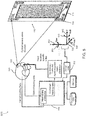
- FIG 1 A first figure.
- FIG. 1 a diagram of an exploded view of a display incorporating presentation of a bezel embedded head tracking fiducial in accordance with an embodiment of the inventive concepts disclosed herein is shown.
- display devices disclosed herein may function to provide a spatially diverse constellation of illuminated fiducial markers embedded within an aircraft display bezel.
- the fiducial makers may provide sufficient number and data available to an HWD and HMD (hereinafter commonly referred to as HWD) system to determine a high integrity six axis pose of a head reference frame enabling the HWD system to present a high integrity primary flight display to the pilot without requiring an additional flight display available.
- HWD HMD
- the an error overbounding may be provided in the approach described within U.S. Patent App. No. 16/263,388 entitled "High-Integrity Optical Pose Estimation Using Coded Features" by using fiducial markers that encode a sufficient number of bits with some minimum Hamming distance (or similar metric) between markers. For example, to achieve a desired low error rate for marker correspondence with a constellation of a specific number of markers, each marker may encode a specific amount of data to achieve the desired low error rate.
- a display exploded view 100 of a presentation of a bezel embedded head tracking fiducial may include an aircraft display 102 within an aircraft cockpit onboard an aircraft.
- the aircraft display 102 may include a display screen 140, a backlight layer 130, and the bezel 110.
- a plurality of bezel embedded head tracking fiducials 114 may enable the HWD system to sense and use the fiducials 114 to determine the high integrity six axis pose of a head reference frame.
- the backlight layer 130 may be configured with a plurality of backlight illuminators 132 configured to actively backlight each of the associated proximal plurality of bezel embedded head tracking fiducials 114.
- an aircraft power 152 may supply the display screen 140 and a display electrical power 154 may also be routed to each of the backlight illuminators 132.
- the backlight layer 130 does not require a separate power source and may receive power directly from the display electrical power 154.
- Each of the backlight illuminators 132 may be positioned in a specific location (e.g., a corner) as well as surrounding a whole of the bezel 110 perimeter.
- the backlight layer 130 may be fitted with illuminators 132 proximal with the bezel and capable of emitting light within a plurality of wavelengths at a plurality of selectable illumination levels.
- a visible wavelength may be appropriate in, for example, a low threat environment during night operations.
- variable colors of backlight may include an exemplary pilot selectable red, blue, green, white, etc. may function to adequately illuminate the fiducial 114 from behind to enable tracking by the HWD system optical sensor.
- the backlight illuminator 132 is pilot selectable to a plurality of illumination levels and desired settings including an on position, an off position, and an automatic position based on a setting of the aircraft display 102.
- a backlit fiducial 114 may be appropriately lighted with a short-wave infrared (SWIR) backlight illuminator 132.
- the SWIR illuminator may provide a specific wavelength compatible with a plurality of night vision imaging systems (NVIS) in use by the HWD (e.g., class A, B, C).
- NVIS night vision imaging systems
- the SWIR backlight illuminators 132 may be specifically tuned to a desired frequency outside the NVIS reception capability.
- the backlight may be separate from a wavelength detectable by the NVIS associated with the HWD system.
- the SWIR backlight illuminator 132 is in an always on position enabling the HWD sensor to recognize the fiducials 114 whether the NVIS system is in use or not.
- the backlight illumination may come from a portion of illumination from the display 140 itself requiring no additional illuminators 132 added to the display.
- a light channel 142 or similar device may be added to the bezel 110 to harness an available light source enabling emissive active illumination from the display 140 screen (e.g., LCD backlight) to backlight the fiducials 114.
- the bezel embedded fiducials 114 may be configured of specially designed material to block the visible spectrum and produce a specific wavelength during certain operations.
- an emissive display may include border pixels available to produce a backlight emissive illumination 144 of the bezel embedded fiducials 114.
- the display 140 may be enlarged to accommodate the additional pixel in addition to slightly enlarging the bezel 110 to accommodate the bezel embedded fiducials 114 backlight by the display 140.
- the bezel embedded head tracking fiducials 114 may be embedded within the bezel 110 and include a coded feature for recognition by an optical tracker associated with the HWD system.
- a constellation of bezel embedded head tracking fiducials 114 in a priori display locations or locations unknown to the HWD system may enable the HWD system to determine a six axis pose of the head reference frame associated with the HWD system.
- no additional information may be required for the HWD to realize the location of the expected fiducials 114. For example, no additional test flight or mapping information may be required since the constellation location and displays are known to the HWD system.
- the bezel embedded head tracking fiducials 114 may be a three-dimensional physical cavity within the bezel (e.g., machined in to the bezel) to allow the illumination to pass through the bezel 110.
- the coded data feature may be machined within the bezel as, for example, a series of small holes and opaque portions within the bezel.
- the bezel embedded head tracking fiducials 114 may include a translucent material embedded within the bezel enabling throughput of the illumination.
- the bezel embedded head tracking fiducials 114 may include a transparent material embedded within the bezel to allow a greater amount of the illumination through the bezel 110. Contemplated herein, each bezel 110 may be entirely translucent/transparent with the bezel embedded head tracking fiducials 114 incorporated therein.
- One advantage of incorporating the bezel embedded head tracking fiducials 114 may include a cost-effective method for integrating and presenting head tracking fiducials without using additional space or clutter within the cockpit.
- Each aircraft display 102 may be inherently located within a field of view (FOV) of the pilot and therefore within a FOV of the optical sensor of the HWD system. Since the bezels 110 may be previously included within a zero-fuel weight of the aircraft, no additional weight may be realized with an addition of the bezel embedded head tracking fiducials 114.
- FOV field of view
- An aircraft display view 200 may include the bezel 110 with the bezel embedded head tracking fiducials 114 located here in each corner of the aircraft display 102.
- a display content 244 may present traditional information to the pilot via the visual display.
- the bezel embedded head tracking fiducials 114 may include a fiducial position marker 220 functional to enable the optical sensor to location the fiducial as well as a fiducial information 222 containing the coded feature and data usable by the HWD system.
- a backlight fiducial view 300 may include a fiducial passive view 314, an active backlight fiducial 324, and a colored fiducial 334.
- each of the plurality of bezel embedded head tracking fiducials 114 may be actively illuminated by the backlight layer 130 as well as passively conspicuous to an optical sensor associated with the HWD system.
- FIG. 3A may detail the passive view 314 to include those pixels coated with material reflective to ambient cockpit light at a specific wavelength outside that of the NVIS onboard the aircraft to ensure the HWD sensor and a NVIS sensor are wavelength separated.
- the bezel embedded head tracking fiducials 114 may include a two-dimensional pattern of a material configured for reflection of a wavelength separate from the NVIS associated with the HWD system.
- one fiducial 114 may include the opaque pixel 302 coated with a reflective material while an adjacent pixel 304 may be translucent.
- the HWD system may recognize the opaque 302 and translucent 304 pixels for the data they present while being illuminated with ambient cockpit light.
- FIG. 3B may detail an exemplary active backlight fiducial 324 enabling the illumination from the backlight layer 130 to pass through the bezel 110.
- an exemplary translucent bezel may include an opaque pixel 302 oriented to be recognized by the optical tracker associated with the HWD system.
- the opaque pixel 302 may function to block the backlit illumination.
- a translucent pixel 304 may function to transmit the backlit illumination from the illuminators 132 to the HWD system optical sensor.
- each pixel may be configured with a level of translucence enabling the optical sensor to distinguish one pixel from another.
- FIG. 3C may detail a colored fiducial 334 including a variable translucence of an individual pixel to move the data available to the fiducial from binary to a greater number (e.g., base 3 or base 4) to encode additional data within a smaller area.
- Each individually colored pixel may offer a greater amount of data than would a binary pixel (e.g., black and white) colored within the same space.
- a red pixel 306, a green pixel 308, and a grey pixel 310, (including additional available luminance and wavelength pixels) may offer additional coded features to the bezel embedded head tracking fiducials 114 by functioning to block light outside of the desired wavelength.
- the colored fiducial 334 may offer approximately twice the coded feature data available to the HWD system of a smaller fiducial 114 may offer information sufficient to determine the six axis pose.
- a 4-pixel binary marker 314 324 may be required.
- each pixel may represent an exemplary 4 different values (e.g. black white red green)
- a 2-pixel colored marker within the variable frequency fiducial 334 may present a similar 16 unique codes to the HMD system.
- changing a translucence property of the individual pixel to a shade of grey may present the desired information.
- changing a reflective material to reflect a specific wavelength may present the desired coded feature.
- a cockpit constellation 400 may include a plurality of the bezel embedded head tracking fiducials 114 oriented in a priori locations easily recognizable by the HWD optical sensor.
- Onboard displays may include a multi-function display (MFD), a head up display (HUD), a flight management system (FMS) display, and a control display navigation unit (CDNU) onboard the aircraft in which the bezel embedded head tracking fiducials 114 may be employed.
- MFD multi-function display
- HUD head up display
- FMS flight management system
- CDNU control display navigation unit
- a forward panel 402 may include a left MFD 410, a left MFD bezel 412, and a left MFD embedded fiducial 414.
- the forward panel 402 may further include a right MFD 420, a right MFD embedded fiducial 424, a center MFD 430, and a center MFD embedded fiducial 434.
- other locations within a FOV of the pilot may include a CDNU 440, a CDNU embedded fiducial 444, a HUD 450, and a HUD embedded fiducial 454.
- each bezel embedded head tracking fiducial 114 may present a limited amount of information within the coded feature available to the HWD system. However, oriented within the constellation, a plurality of the bezel embedded head tracking fiducials 114 may present sufficient data to the HWD system to reach a desired error rate of the six axis pose. In embodiments, the desired error rate may enable the HWD system to determine, in addition with inertial tracking data, a high integrity six axis pose solution.
- a view of the HWD system 500 may include a head worn device 520 (e.g., a helmet) and an HWD optical sensor 522.
- a controller 510 may function to receive inertial tracking data as well as optical tracking data, perform processing of combined tracking data, reference an internal data and memory, and display symbology / distributed aperture video within the head worn device 520.
- the controller 510 may determine head location specific video based on a determination of the head reference frame.
- the head reference frame may include the six axis pose relative to an aircraft state data 512 including a pitch 530 and X axis (pitch) 532 positions, a roll 540 and Z axis (roll) 542 positions, and a yaw 550 and Y axis (yaw) 552 positions.
- the bezel embedded head tracking fiducials 114 may be oriented within the constellation within the aircraft cockpit so that each fiducial is within a field of view of the optical sensor 522 with the HWD 520 oriented toward the display 140.
- the bezel embedded head tracking fiducials 114 may be in locations previously unknown to the HWD system where the HWD sensor 522 may sense the fiducials 114, map the constellation of fiducials, and determine the six axis pose based on the sensed constellation and reception of the aircraft state data 512.
- the constellation may employ a number and spatial orientation of the bezel embedded head tracking fiducial 114 with coded data sufficient to achieve the desired error rate.
- the bezel embedded head tracking fiducials 114 may enable the HWD system to present, using optical tracking data as well as inertial tracking data, a high integrity primary flight display to the pilot without requiring an additional flight display available.
- a method flow 600 for presentation of a bezel embedded head tracking fiducial may include, at a step 602, embedding at least one bezel embedded head tracking fiducial within a bezel of a display in an cockpit onboard on aircraft, the at least one bezel embedded head tracking fiducial including a coded data and configured for recognition by an optical tracker associated with a head worn display (HWD) system.
- HWD head worn display
- a step 604 may include orienting the at least one bezel embedded head tracking fiducial in a constellation to enable the HWD system to determine a six axis pose of a head reference frame associated with the HWD system, the six axis pose relative to the aircraft and including each of: an x position, a y position, a z position, a pitch position, a roll position, and a yaw position.
- a step 606 may include configuring each of the at least one bezel embedded head tracking fiducial with information sufficient for the HWD system to determine, combined with additional ones of the at least one bezel embedded head tracking fiducial within the constellation, the six axis pose within a desired error rate while a step 608 may include illuminating the at least one bezel embedded head tracking fiducial with a power source of the display.
- embedding the bezel embedded head tracking fiducial within a bezel of a display may further comprise opening a physical cavity within the bezel, forming the bezel of a translucent material, and machining a three-dimensional cavity within the bezel to create a contrast fiducial within the bezel.
- embodiments of the inventive concepts disclosed herein may provide a novel solution to leverage existing space surrounding a cockpit display to enable accurate head tracking relative to the aircraft without the integration complexity added by requiring separate fiducial markers.
- embodiments of the methods according to the inventive concepts disclosed herein may include one or more of the steps described herein. Further, such steps may be carried out in any desired order and two or more of the steps may be carried out simultaneously with one another. Two or more of the steps disclosed herein may be combined in a single step, and in some embodiments, one or more of the steps may be carried out as two or more sub-steps. Further, other steps or sub-steps may be carried in addition to, or as substitutes to one or more of the steps disclosed herein.
Landscapes
- Engineering & Computer Science (AREA)
- Physics & Mathematics (AREA)
- Theoretical Computer Science (AREA)
- General Physics & Mathematics (AREA)
- General Engineering & Computer Science (AREA)
- Human Computer Interaction (AREA)
- Computer Vision & Pattern Recognition (AREA)
- Optics & Photonics (AREA)
- Health & Medical Sciences (AREA)
- Electromagnetism (AREA)
- General Health & Medical Sciences (AREA)
- Toxicology (AREA)
- Artificial Intelligence (AREA)
Applications Claiming Priority (1)
| Application Number | Priority Date | Filing Date | Title |
|---|---|---|---|
| US16/665,966 US11036453B1 (en) | 2019-10-28 | 2019-10-28 | Bezel embedded head tracking fiducials |
Publications (1)
| Publication Number | Publication Date |
|---|---|
| EP3816707A1 true EP3816707A1 (fr) | 2021-05-05 |
Family
ID=73037810
Family Applications (1)
| Application Number | Title | Priority Date | Filing Date |
|---|---|---|---|
| EP20204399.8A Pending EP3816707A1 (fr) | 2019-10-28 | 2020-10-28 | Repères de suivi de tête intégrés au cadre |
Country Status (2)
| Country | Link |
|---|---|
| US (1) | US11036453B1 (fr) |
| EP (1) | EP3816707A1 (fr) |
Families Citing this family (2)
| Publication number | Priority date | Publication date | Assignee | Title |
|---|---|---|---|---|
| US11513360B2 (en) * | 2020-07-17 | 2022-11-29 | Toyota Research Institute, Inc. | Enhanced contrast augmented reality (AR) tags for visual fiducial system |
| US11768374B1 (en) * | 2022-06-24 | 2023-09-26 | Rockwell Collins, Inc. | Vehicle including head wearable display device and imperceptible reference fiducials and method therefor |
Citations (4)
| Publication number | Priority date | Publication date | Assignee | Title |
|---|---|---|---|---|
| US20100295754A1 (en) * | 2009-05-19 | 2010-11-25 | Honeywell International Inc. | Systems, apparatus and fast methods for aligning images to external markers in near-to-eye display systems |
| US20160339337A1 (en) * | 2015-05-21 | 2016-11-24 | Castar, Inc. | Retroreflective surface with integrated fiducial markers for an augmented reality system |
| US9874931B1 (en) * | 2016-02-22 | 2018-01-23 | Rockwell Collins, Inc. | Head-tracking system and method |
| US9891705B1 (en) * | 2016-08-25 | 2018-02-13 | Rockwell Collins, Inc. | Automatic boresighting of head-worn display |
Family Cites Families (1)
| Publication number | Priority date | Publication date | Assignee | Title |
|---|---|---|---|---|
| FR3011952B1 (fr) * | 2013-10-14 | 2017-01-27 | Suricog | Procede d'interaction par le regard et dispositif associe |
-
2019
- 2019-10-28 US US16/665,966 patent/US11036453B1/en active Active
-
2020
- 2020-10-28 EP EP20204399.8A patent/EP3816707A1/fr active Pending
Patent Citations (4)
| Publication number | Priority date | Publication date | Assignee | Title |
|---|---|---|---|---|
| US20100295754A1 (en) * | 2009-05-19 | 2010-11-25 | Honeywell International Inc. | Systems, apparatus and fast methods for aligning images to external markers in near-to-eye display systems |
| US20160339337A1 (en) * | 2015-05-21 | 2016-11-24 | Castar, Inc. | Retroreflective surface with integrated fiducial markers for an augmented reality system |
| US9874931B1 (en) * | 2016-02-22 | 2018-01-23 | Rockwell Collins, Inc. | Head-tracking system and method |
| US9891705B1 (en) * | 2016-08-25 | 2018-02-13 | Rockwell Collins, Inc. | Automatic boresighting of head-worn display |
Also Published As
| Publication number | Publication date |
|---|---|
| US11036453B1 (en) | 2021-06-15 |
Similar Documents
| Publication | Publication Date | Title |
|---|---|---|
| EP3786686B1 (fr) | Dispositif d'éclairage à double mode permettant une imagerie dans différentes conditions d'éclairage | |
| US9791694B1 (en) | Transparent film display system for vehicles | |
| CN102862683B (zh) | 飞行器飞行驾驶台的可视显示器 | |
| EP3816707A1 (fr) | Repères de suivi de tête intégrés au cadre | |
| US10578863B2 (en) | Heads up display, heads up display method, and traveling apparatus | |
| US9170643B2 (en) | Display system containing an adaptive semi-transparent display device and means for detecting the landscape viewed by the user | |
| WO2010045411A1 (fr) | Dispositif d’affichage en superposition | |
| GB2213019A (en) | Head-up display systems. | |
| US7592926B2 (en) | Light-emitting diode assembly for use in heads-up display systems of propeller-driven aircraft | |
| US20080186155A1 (en) | Persistence of Vision Display | |
| US7081828B2 (en) | Heads-up display for propeller-driven aircraft | |
| ES2957292T3 (es) | Aparato y método para definir e interactuar con regiones de un área operativa | |
| US20210278666A1 (en) | A Display System | |
| US20160085073A1 (en) | Semitransparent monocular viewing system | |
| EP3816708A1 (fr) | Obturateur de sécurité de lumière de réalité augmentée | |
| EP3112265A1 (fr) | Système deformation-lumière bimode | |
| IL189808A (en) | System and method for optimizing display uniformity of graphical elements in user interface | |
| US11768374B1 (en) | Vehicle including head wearable display device and imperceptible reference fiducials and method therefor | |
| US11905034B2 (en) | Omnidirectional light drone show | |
| US10681316B1 (en) | Passive head worn display | |
| US20210310808A1 (en) | Method of displaying compass headings | |
| EP3705928A1 (fr) | Réticule orientable pour affichages montés sur casque et projetés sur la visière | |
| EP3767368A1 (fr) | Dispositif monté sur la tête à diode électroluminescente organique transparente | |
| US9746355B2 (en) | Systems and methods for selective contextual illumination of digital information display devices and other information indication devices | |
| JP2021182259A (ja) | 検出用マーカ |
Legal Events
| Date | Code | Title | Description |
|---|---|---|---|
| PUAI | Public reference made under article 153(3) epc to a published international application that has entered the european phase |
Free format text: ORIGINAL CODE: 0009012 |
|
| STAA | Information on the status of an ep patent application or granted ep patent |
Free format text: STATUS: THE APPLICATION HAS BEEN PUBLISHED |
|
| AK | Designated contracting states |
Kind code of ref document: A1 Designated state(s): AL AT BE BG CH CY CZ DE DK EE ES FI FR GB GR HR HU IE IS IT LI LT LU LV MC MK MT NL NO PL PT RO RS SE SI SK SM TR |
|
| STAA | Information on the status of an ep patent application or granted ep patent |
Free format text: STATUS: REQUEST FOR EXAMINATION WAS MADE |
|
| 17P | Request for examination filed |
Effective date: 20211105 |
|
| RBV | Designated contracting states (corrected) |
Designated state(s): AL AT BE BG CH CY CZ DE DK EE ES FI FR GB GR HR HU IE IS IT LI LT LU LV MC MK MT NL NO PL PT RO RS SE SI SK SM TR |
|
| STAA | Information on the status of an ep patent application or granted ep patent |
Free format text: STATUS: EXAMINATION IS IN PROGRESS |
|
| 17Q | First examination report despatched |
Effective date: 20230404 |