EP3816695A1 - Zoom lens and image pickup apparatus - Google Patents
Zoom lens and image pickup apparatus Download PDFInfo
- Publication number
- EP3816695A1 EP3816695A1 EP20204343.6A EP20204343A EP3816695A1 EP 3816695 A1 EP3816695 A1 EP 3816695A1 EP 20204343 A EP20204343 A EP 20204343A EP 3816695 A1 EP3816695 A1 EP 3816695A1
- Authority
- EP
- European Patent Office
- Prior art keywords
- lens
- lens unit
- extender
- zoom
- zoom lens
- Prior art date
- Legal status (The legal status is an assumption and is not a legal conclusion. Google has not performed a legal analysis and makes no representation as to the accuracy of the status listed.)
- Granted
Links
Images







Classifications
-
- G—PHYSICS
- G02—OPTICS
- G02B—OPTICAL ELEMENTS, SYSTEMS OR APPARATUS
- G02B15/00—Optical objectives with means for varying the magnification
- G02B15/02—Optical objectives with means for varying the magnification by changing, adding, or subtracting a part of the objective, e.g. convertible objective
- G02B15/04—Optical objectives with means for varying the magnification by changing, adding, or subtracting a part of the objective, e.g. convertible objective by changing a part
- G02B15/08—Optical objectives with means for varying the magnification by changing, adding, or subtracting a part of the objective, e.g. convertible objective by changing a part by changing the rear part
-
- G—PHYSICS
- G02—OPTICS
- G02B—OPTICAL ELEMENTS, SYSTEMS OR APPARATUS
- G02B15/00—Optical objectives with means for varying the magnification
- G02B15/14—Optical objectives with means for varying the magnification by axial movement of one or more lenses or groups of lenses relative to the image plane for continuously varying the equivalent focal length of the objective
- G02B15/16—Optical objectives with means for varying the magnification by axial movement of one or more lenses or groups of lenses relative to the image plane for continuously varying the equivalent focal length of the objective with interdependent non-linearly related movements between one lens or lens group, and another lens or lens group
- G02B15/20—Optical objectives with means for varying the magnification by axial movement of one or more lenses or groups of lenses relative to the image plane for continuously varying the equivalent focal length of the objective with interdependent non-linearly related movements between one lens or lens group, and another lens or lens group having an additional movable lens or lens group for varying the objective focal length
-
- G—PHYSICS
- G02—OPTICS
- G02B—OPTICAL ELEMENTS, SYSTEMS OR APPARATUS
- G02B15/00—Optical objectives with means for varying the magnification
- G02B15/14—Optical objectives with means for varying the magnification by axial movement of one or more lenses or groups of lenses relative to the image plane for continuously varying the equivalent focal length of the objective
- G02B15/145—Optical objectives with means for varying the magnification by axial movement of one or more lenses or groups of lenses relative to the image plane for continuously varying the equivalent focal length of the objective having five groups only
- G02B15/1451—Optical objectives with means for varying the magnification by axial movement of one or more lenses or groups of lenses relative to the image plane for continuously varying the equivalent focal length of the objective having five groups only the first group being positive
- G02B15/145125—Optical objectives with means for varying the magnification by axial movement of one or more lenses or groups of lenses relative to the image plane for continuously varying the equivalent focal length of the objective having five groups only the first group being positive arranged +--++
-
- G—PHYSICS
- G02—OPTICS
- G02B—OPTICAL ELEMENTS, SYSTEMS OR APPARATUS
- G02B27/00—Optical systems or apparatus not provided for by any of the groups G02B1/00 - G02B26/00, G02B30/00
- G02B27/0025—Optical systems or apparatus not provided for by any of the groups G02B1/00 - G02B26/00, G02B30/00 for optical correction, e.g. distorsion, aberration
Definitions
- the present invention relates to a zoom lens and an image pickup apparatus.
- a zoom lens For performing image capturing for a television program or a film (for example, outdoor image capturing of an animal or a human from a long distance), there is demand for a zoom lens having a high zooming ratio and high optical performance. Because such image capturing is often performed in a state where a camera is held on a shoulder, there is demand for a zoom lens advantageous also from the aspects of downsizing, weight saving, and portability.
- a teleconverter is used for changing a focal length range to a longer focal length range.
- Some zoom lenses for television cameras incorporate an extender (extender lens unit) insertable and removable into and from an afocal optical path in a relay lens unit. In the zoom lenses, even when a focal length range is switched by the insertion or removal of the extender, a total lens length and a back focus do not change.
- a camera equipped with a large-sized image pickup element that is advantageous for image capturing under the environment with low illuminance can be used.
- a zoom lens with a high zooming ratio that is excellent in portability and mobility while having an image circle corresponding to the large-sized image pickup element.
- Japanese Patent Laid-Open No. 2016-45310 discusses a zoom lens incorporating an extender that is advantageous from the aspects of a large image circle, a high zooming ratio, downsizing, and weight saving.
- An aspect of embodiments provides, for example, a zoom lens, including an extender lens unit therein, beneficial in a large image circle, small size, and high optical performance.
- the present invention in its first aspect provides a zoom lens as specified in claims 1 to 8.
- the present invention in its second aspect provides an image pickup apparatus as specified in claim 9.
- Fig. 1 is a cross-sectional diagram illustrating a zoom lens according to the first exemplary embodiment that is set at a wide-angle end and in a state where a focus is placed on an object at infinity and an extender lens unit is removed.
- the zoom lens illustrated in Fig. 1 includes a first lens unit U1 that has positive refractive power and does not move for zooming.
- a partial lens unit of the first lens unit U1 can move for focusing along an optical axis.
- the zoom lens further includes a second lens unit U2 (first variator) having negative refractive power.
- the second lens unit U2 moves (monotonically in one direction, for example) toward an image side along an optical axis for zooming from a wide-angle end (short focal length end) to a telephoto end (long focal length end).
- the zoom lens further includes a third lens unit U3 (second variator) having negative refractive power.
- the third lens unit U3 moves (not monotonically in one direction, for example) along the optical axis for the zooming.
- the zoom lens further includes a fourth lens unit U4 (compensator) having positive refractive power.
- the fourth lens unit U4 moves (not monotonically in one direction, for example) along the optical axis for the zooming (correction (compensation) of a variation in an image plane position that is attributed to the zooming).
- the zoom lens further includes an aperture stop SP.
- the zoom lens further includes a lens unit UR1 (front relay lens unit; R1 lens unit) that does not move for zooming.
- the zoom lens further includes a lens unit UR2 (rear relay lens unit; R2 lens unit) that does not move for zooming.
- An image plane IP corresponds to a plane on which a light receiving surface of an image pickup element (photoelectric conversion element) that receives light of an image formed by the zoom lens is arranged.
- the zoom lens further includes an extender lens unit UEXT (EXT lens unit) to be inserted or removed into or from an optical path between the R1 lens unit and the R2 lens unit (typically, an optical path of afocal light) for changing a focal length range of the zoom lens.
- EXT lens unit extender lens unit
- the first lens unit U1 includes first to 13th surfaces, and consists of a negative lens, a positive lens, a positive lens, a cemented lens of a negative lens and a positive lens, a positive lens, and a positive lens (seven lenses).
- the second lens unit U2 includes 14th to 20th surfaces, and consists of a negative lens, a cemented lens of a negative lens and a positive lens, and a negative lens (four lenses).
- the third lens unit U3 includes 21st to 23rd surfaces, and consists of a cemented lens of a positive lens and a negative lens (two lenses).
- the fourth lens unit U4 includes 24th to 28th surfaces, and consists of a positive lens, and a cemented lens of a negative lens and a positive lens (three lenses).
- the lens unit UR1 includes 30th to 34th surfaces, and consists of a cemented lens of a positive lens and a negative lens, and a positive lens (three lenses).
- the lens unit UR2 includes 35th to 44th surfaces, and consists of a positive lens, a cemented lens of a positive lens and a negative lens, a cemented lens of a positive lens and a negative lens, and a positive lens (six lenses).
- the extender lens unit UEXT is insertable and removable into and from an optical path between the 34th and 35th surfaces, and consists of a positive lens, a cemented lens of a negative lens and a positive lens, a cemented lens of a negative lens and a positive lens, and a negative lens (six lenses).
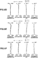
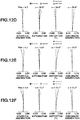
- Figs. 2A to 2F are aberration diagrams of the zoom lens according to the present exemplary embodiment (Numerical Example 1 corresponding to the present exemplary embodiment).
- Figs. 2A, 2B, and 2C illustrate longitudinal aberrations in a state where the zoom lens is set at the wide-angle end, in a state where a focal length is 177.00 mm, and in a state where the zoom lens is set at the telephoto end, respectively, in a state where a focus is placed on an object at infinity and the extender lens unit is removed.
- Figs. 2A to 2F are aberration diagrams of the zoom lens according to the present exemplary embodiment (Numerical Example 1 corresponding to the present exemplary embodiment).
- Figs. 2A, 2B, and 2C illustrate longitudinal aberrations in a state where the zoom lens is set at the wide-angle end, in a state where a focal length is 177.00 mm, and in a state where the zoom lens is set at the telephoto end, respectively, in
- 2D, 2E, and 2F illustrate longitudinal aberrations in a state where the zoom lens is set at the wide-angle end, in a state where a focal length is 260.19 mm, and in a state where the zoom lens is set at the telephoto end, respectively, in a state where a focus is placed on an object at infinity and the extender lens unit is inserted.
- spherical aberration is aberration with respect to an e-line (solid line) and a g-line (dotted line).
- Astigmatism is aberration on a meridional image plane (dotted line) and a sagittal image plane (solid line) with respect to the e-line.
- Magnification chromatic aberration is aberration with respect to the g-line (dotted line).
- Fno denotes an F-number and ⁇ denotes a half field angle.
- a scale in the longitudinal aberration diagrams defines that, in a state where the extender lens unit is removed, spherical aberration is 0.4 mm, astigmatism is 0.4 mm, distortion is 10%, and magnification chromatic aberration is 0.1 mm.
- the same scale defines that, in a state where the extender lens unit is inserted, spherical aberration is 0.8 mm, astigmatism is 0.8 mm, distortion is 10%, and magnification chromatic aberration is 0.1 mm.
- the wide-angle end and the telephoto end correspond to the ends of a movable range of the second lens unit U2.
- Graph legends in longitudinal aberration diagrams in other examples are given similarly to the graph legends in these longitudinal aberration diagrams.
- a zoom ratio is 9.62 and magnification of the extender lens unit is 1.47.
- a half field angle at the wide-angle end is 29.7 degrees
- a half field angle at the telephoto end is 3.39 degrees
- a maximum image height is 14.8 mm.
- a maximum image height is increased to 21.64 mm.
- An extender lens unit incorporated in a zoom lens supporting a large-sized image pickup element such as a zoom lens used for film image capturing needs to ensure a light amount up to the end of the image pickup element. It is therefore necessary to determine an effective diameter of a lens closest to an image based on an off-axis ray, and a ratio between an effective diameter of a lens closest to an object and an effective diameter of a lens closest to an image becomes smaller than enlargement magnification (transverse magnification) of the extender lens unit.
- an effective diameter of a lens closest to the image in a lens unit closest to the image also needs to be determined based on an off-axis ray
- an effective diameter of a lens on the image side of the extender lens unit increases, and the zoom lens upsizes.
- the zoom lens according to the present exemplary embodiment blunts an incident angle of an off-axis ray to the extender lens unit by causing a converging on-axis ray to enter the extender lens unit.
- an effective diameter of a lens of the extender lens unit that is closest to the image is appropriately set.
- the present exemplary embodiment can provide a zoom lens incorporating an extender lens unit that is advantageous from the aspects of a large image circle, downsizing, and high optical performance.
- the zoom lens according to the present exemplary embodiment includes, in order from an object side to an image side, the first lens unit that does not move for zooming, and a plurality of zooming lens units that moves for zooming.
- the zoom lens further includes the R1 lens unit that does not move for zooming, the extender lens unit insertable and removable into and from an optical path, and the R2 lens unit that does not move for zooming.
- the zoom lens according to the present exemplary embodiment satisfies the following inequalities: 0.50 ⁇ Def / Der / ⁇ e + 1 ⁇ few / feF ⁇ 1.75 and 0.50 ⁇ le / Der / ⁇ e ⁇ 1.22
- feF is a combined focal length from the first lens unit to the R1 lens unit
- Def is an effective diameter of a lens of the extender lens unit that is closest to an object
- Der is an effective diameter of the extender lens unit that is closest to an image
- ⁇ e is transverse magnification of the extender lens unit
- le is an overall thickness (a distance on the optical axis from a lens surface closest to an object to a lens surface closest to an image) of the extender lens unit.
- An effective diameter of the zoom lens on each surface is defined as a double of a maximum light ray height on the corresponding surface.
- the maximum light ray height in a lens or a lens unit is assumed to be the maximum light ray height among a plurality of maximum light ray heights on a plurality of surfaces included in the lens or the lens unit.
- Inequality (1) defines a relationship between the following three amounts a to c.
- the amount c) defined as (few/feF) indicates an incident angle of a paraxial on-axis ray to the extender lens unit, and when the paraxial on-axis ray is parallel to the optical axis, (few/feF) becomes 0.
- Inequality (1) defines a relationship between the incident angle of the paraxial on-axis ray to the extender lens unit and an effective diameter of the extender lens unit.
- the converging paraxial on-axis ray means that an incident angle of an off-axis ray becomes smaller.
- a value of Inequality (1) exceeds an upper limit, a diameter of a lens on the image side of the extender lens unit becomes too large, which is disadvantageous from the aspect of downsizing of the zoom lens. If a value of Inequality (1) falls below a lower limit, although the zoom lens becomes advantageous from the aspect of downsizing of the zoom lens, refractive power of each lens of the extender lens unit becomes too large, which is disadvantageous from the aspect of aberration correction of the zoom lens.
- the zoom lens more preferably satisfies the following inequality: 1.00 ⁇ Def / Der / 1 ⁇ few / feF ⁇ 1.73
- Inequality (2) defines a relationship between the following two amounts d and e.
- the zoom lens becomes advantageous from the aspects of downsizing of the extender lens unit and high optical performance over the entire zoom range. If a value of Inequality (2) exceeds an upper limit, the overall thickness of the extender lens unit becomes too large and refractive power of each lens becomes too small, which is advantageous from the aspect of aberration correction, but the zoom lens becomes disadvantageous from the aspect of downsizing of the extender lens unit. If a value of Inequality (2) falls below a lower limit, although the zoom lens becomes advantageous from the aspect of downsizing of the extender lens unit, refractive power of each lens becomes too large, which is disadvantageous from the aspect of aberration correction.
- the zoom lens more preferably satisfies the following inequality: 0.70 ⁇ le / Der / ⁇ e ⁇ 1.20
- the zoom lens according to the present exemplary embodiment can provide a zoom lens incorporating an extender lens unit that is advantageous from the aspects of a large image circle, downsizing, and high optical performance.
- the zoom lens according to the present exemplary embodiment further satisfies the following inequality (3): 1.10 ⁇ few / feF ⁇ 1.00
- the zoom lens becomes advantageous from the aspects of downsizing and high optical performance over the entire zoom range. If a value of Inequality (3) exceeds an upper limit, an incident angle of an on-axis ray to the extender lens unit becomes too large (an incident angle of an off-axis ray becomes too small), which is advantageous from the aspect of downsizing of the zoom lens. Although the zoom lens becomes advantageous, refractive power of each lens of the extender lens unit becomes too large, which is disadvantageous from the aspect of aberration correction of the zoom lens.
- the zoom lens more preferably satisfies the following inequality: 0.20 ⁇ few / fF ⁇ 0.80
- the zoom lens according to the present exemplary embodiment further satisfies the following inequality (4) 0.10 ⁇ few / f 1 ⁇ 0.80 where f1 is a focal length of the first lens unit.
- the zoom lens becomes advantageous from the aspects of a sufficient light amount in a large image circle, high optical performance, and downsizing. If a value of Inequality (4) exceeds an upper limit, although the zoom lens becomes advantageous from the aspect of a light amount, the focal length f1 becomes relatively small. The zoom lens therefore becomes disadvantageous from the aspect of aberration correction of the zoom lens. If a value of Inequality (4) falls below a lower limit, although the zoom lens becomes advantageous from the aspect of aberration correction of the zoom lens, the zoom lens becomes disadvantageous from the aspect of a light amount. If a lens diameter is increased for ensuring a light amount, the zoom lens becomes disadvantageous from the aspect of downsizing.
- the zoom lens more preferably satisfies the following inequality: 0.20 ⁇ few / f 1 ⁇ 0.70
- the zoom lens according to the present exemplary embodiment further satisfies the following inequality (5): 0.30 ⁇ ⁇ z ⁇ 0.70 where ⁇ z is transverse magnification of a zooming lens unit that has negative refractive power and is closest to the image among a plurality of zooming lens units that moves for zooming.
- the zoom lens becomes advantageous from the aspects of high optical performance over the entire zoom range and downsizing. If a value of Inequality (5) exceeds an upper limit, aberration is excessively augmented due to too large transverse magnification ⁇ z, which is disadvantageous from the aspect of aberration correction of the zoom lens. If a value of Inequality (5) falls below a lower limit, the transverse magnification ⁇ z becomes small, and a movement amount of a lens unit having the transverse magnification ⁇ z increases for obtaining a high zooming ratio. The total lens length therefore increases, which is disadvantageous from the aspect of downsizing.
- the zoom lens more preferably satisfies the following inequality: 0.40 ⁇ ⁇ z ⁇ 0.60
- the zoom lens according to the present exemplary embodiment further satisfies the following inequality (6): 1.20 ⁇ ⁇ e ⁇ 1.80 where ⁇ e is transverse magnification of the extender lens unit.
- the zoom lens becomes advantageous from the aspects of high optical performance over the entire zoom range and downsizing. If a value of Inequality (6) exceeds an upper limit, for obtaining high optical performance, the extender lens unit becomes too large in the direction of the optical axis. If a value of Inequality (6) falls below a lower limit, although the zoom range becomes advantageous from the aspect of aberration correction of the zoom lens, a lens diameter of the extender lens unit becomes too large.
- the zoom lens more preferably satisfies the following inequality: 1.30 ⁇ ⁇ e ⁇ 1.70
- the zoom lens according to the present exemplary embodiment satisfies the following inequality (7): 1.00 ⁇ R 12 + R 11 / R 12 ⁇ R 11 ⁇ 2.00 where R11 is a curvature radius of a surface on the object side of a single lens of the extender lens unit that is closest to the object, and R12 is a curvature radius of a surface on the image side of the single lens.
- Satisfying Inequality (7) means that the single lens is a convex meniscus lens. If a value of Inequality (7) exceeds an upper limit, although the zoom lens becomes advantageous from the aspect of aberration correction of the zoom lens, the zoom lens becomes disadvantageous from the aspect of downsizing of the extender lens unit. If a value of Inequality (7) falls below a lower limit, because the single lens becomes a biconvex lens, although the zoom lens becomes advantageous from the aspect of downsizing, the zoom lens becomes disadvantageous from the aspect of aberration correction of the zoom lens.
- the zoom lens more preferably satisfies the following inequality: 1.10 ⁇ R 12 + R 11 / R 12 ⁇ R 11 ⁇ 1.7
- the zoom lens according to the present exemplary embodiment further satisfies the following inequality (8): 0.25 ⁇ hr / Der ⁇ 0.50 where hr is a height of an on-axis ray on a surface of the extender lens unit that is closest to an image in a state where a focus is placed on an object at infinity and the zoom lens is set at the wide-angle end.
- the zoom lens becomes advantageous from the aspects of a light amount in an image circle peripheral portion and downsizing of the extender lens unit. If a value of Inequality (8) exceeds an upper limit, although the zoom lens becomes advantageous from the aspect of downsizing of the extender lens unit, the zoom lens becomes disadvantageous from the aspect of a light amount in an image circle peripheral portion. If a value of Inequality (8) falls below a lower limit, although the zoom lens becomes advantageous from the aspect of a light amount in an image circle peripheral portion, the zoom lens becomes disadvantageous from the aspect of downsizing of the zoom lens.
- the zoom lens more preferably satisfies the following inequality: 0.30 ⁇ hr / Der ⁇ 0.48
- the zoom lens according to the present exemplary embodiment further satisfies the following inequality (9): 1.00 ⁇ fe 1 / Der ⁇ 3.80 where fe1 is a focal length of a lens of the extender lens unit that is closest to the obj ect.
- the zoom lens becomes advantageous from the aspects of downsizing of the extender lens unit, a light amount in an image circle peripheral portion, and high optical performance over the entire zoom range. If a value of Inequality (9) exceeds an upper limit, although the zoom lens becomes advantageous from the aspect of aberration correction of the zoom lens because refractive power of the lens becomes too small, the zoom lens becomes disadvantageous from the aspect of downsizing of the extender lens unit, and becomes disadvantageous also from the aspect of a light amount in an image circle peripheral portion.
- the zoom lens more preferably satisfies the following inequality: 1.50 ⁇ fe 1 / Der ⁇ 3.70
- Numerical value data of Numerical Example 1 corresponding to the first exemplary embodiment will be described below.
- r is a curvature radius of each surface
- d is each surface interval
- vd is an Abbe number.
- nd is an absolute refractive index at 1 atm (atmospheric pressure) with respect to a d-line of Fraunhofer lines.
- Ng, NF, Nd, and NC are refractive indices with respect to a g-line, an F-line, a d-line, and a Cline of Fraunhofer lines, respectively.
- the definitions of the Abbe number vd and a partial dispersion ratio ⁇ gf are similar to generally-used definitions.
- vd Nd ⁇ 1 / NF ⁇ NC
- ⁇ gf Ng ⁇ NF / NF ⁇ NC .
- An aspherical shape is represented assuming that an X-axis is set to the direction of the optical axis, an H-axis is set to a direction orthogonal to the direction of the optical axis, and a travelling direction of light is set as a positive direction.
- R is a paraxial curvature radius
- k is a conic constant
- A3, A4, A5, A6, A7, A8, A9, A10, A11, A12, A13, A14, A15, and A16 are aspherical surface coefficients.
- a focal length, an F-number, and a field angle indicate values in a state where a focus is placed on an object at infinity.
- BF is a distance from a final lens surface to an image plane.
- e-Z means " ⁇ 10 -Z ".
- Numerical Example 1 can provide a zoom lens that satisfies all the inequalities (1) to (9) and incorporates an extender lens unit that is advantageous from the aspects of a large image circle, downsizing, and high optical performance over the entire zoom range.
- Fig. 3 is a cross-sectional diagram illustrating a zoom lens according to the second exemplary embodiment that is set at a wide-angle end and in a state where a focus is placed on an object at infinity and an extender lens unit is removed.
- the zoom lens illustrated in Fig. 3 includes a first lens unit U1 that has positive refractive power, and does not move for zooming.
- a partial lens unit of the first lens unit U1 can move for focusing along an optical axis.
- the zoom lens further includes a second lens unit U2 (first variator) having negative refractive power.
- the second lens unit U2 moves (monotonically in one direction, for example) toward an image side along an optical axis for zooming from a wide-angle end to a telephoto end.
- the zoom lens further includes a third lens unit U3 (second variator) having negative refractive power.
- the third lens unit U3 moves (not monotonically in one direction, for example) along the optical axis for the zooming.
- the zoom lens further includes a fourth lens unit U4 (compensator) having positive refractive power.
- the fourth lens unit U4 moves (not monotonically in one direction, for example) along the optical axis for the zooming (correction (compensation) of a variation in an image plane position that is attributed to the zooming).
- the zoom lens further includes an aperture stop SP.
- the zoom lens further includes a lens unit UR1 (front relay lens unit; R1 lens unit) that does not move for zooming.
- the zoom lens further includes a lens unit UR2 (rear relay lens unit; R2 lens unit) that does not move for zooming.
- An image plane IP corresponds to a plane on which a light receiving surface of an image pickup element (photoelectric conversion element) that receives light of an image formed by the zoom lens is arranged.
- the zoom lens further includes an extender lens unit UEXT (EXT lens unit) to be inserted or removed into or from an optical path between the R1 lens unit and the R2 lens unit (typically, an optical path of afocal light) for changing a focal length range of the zoom lens.
- the first lens unit U1 includes first to 13th surfaces, and consists of a negative lens, a positive lens, a positive lens, a cemented lens of a negative lens and a positive lens, a positive lens, and a positive lens (seven lenses).
- the second lens unit U2 includes 14th to 20th surfaces, and consists of a negative lens, a cemented lens of a negative lens and a positive lens, and a negative lens (four lenses).
- the third lens unit U3 includes 21st to 23rd surfaces, and consists of a cemented lens of a negative lens and a positive lens (two lenses).
- the fourth lens unit U4 includes 24th to 28th surfaces, and consists of a positive lens, and a cemented lens of a negative lens and a positive lens (three lenses).
- the lens unit UR1 includes 30th to 34th surfaces, and consists of a cemented lens of a positive lens and a negative lens, and a positive lens (three lenses).
- the lens unit UR2 includes 35th to 44th surfaces, and consists of a positive lens, a cemented lens of a positive lens and a negative lens, a cemented lens of a positive lens and a negative lens, and a positive lens (six lenses).
- the extender lens unit UEXT is insertable and removable into and from an optical path between the 34th and 35th surfaces, and consists of a positive lens, a cemented lens of a negative lens and a positive lens, a cemented lens of a negative lens and a positive lens, and a negative lens (six lenses).
- Figs. 4A to 4F are aberration diagrams of the zoom lens according to the present exemplary embodiment (Numerical Example 2 corresponding to the present exemplary embodiment).
- Figs. 4A, 4B, and 4C illustrate longitudinal aberrations in a state where the zoom lens is set at the wide-angle end, in a state where a focal length is 179.00 mm, and in a state where the zoom lens is set at the telephoto end, respectively, in a state where a focus is placed on an object at infinity and the extender lens unit is removed.
- Figs. 4A to 4F are aberration diagrams of the zoom lens according to the present exemplary embodiment (Numerical Example 2 corresponding to the present exemplary embodiment).
- Figs. 4A, 4B, and 4C illustrate longitudinal aberrations in a state where the zoom lens is set at the wide-angle end, in a state where a focal length is 179.00 mm, and in a state where the zoom lens is set at the telephoto end, respectively, in a
- 4D, 4E, and 4F illustrate longitudinal aberrations in a state where the zoom lens is set at the wide-angle end, in a state where a focal length is 281.03 mm, and in a state where the zoom lens is set at the telephoto end, respectively, in a state where a focus is placed on an object at infinity and the extender lens unit is inserted.
- a zoom ratio is 9.62 and magnification of the extender lens unit is 1.57.
- a half field angle at the wide-angle end is 29.7 degrees
- a half field angle at the telephoto end is 3.39 degrees
- a maximum image height is 14.8 mm.
- a maximum image height is increased to 23.20 mm.
- Numerical Example 2 can provide a zoom lens that satisfies all the inequalities (1) to (9) and incorporates an extender lens unit that is advantageous from the aspects of a large image circle, downsizing, and high optical performance over the entire zoom range.
- Fig. 5 is a cross-sectional diagram illustrating a zoom lens according to the third exemplary embodiment that is set at a wide-angle end and in a state where a focus is placed on an object at infinity and an extender lens unit is removed.
- the zoom lens includes a first lens unit U1 that has positive refractive power, and does not move for zooming.
- a partial lens unit of the first lens unit U1 can move for focusing along an optical axis.
- the zoom lens further includes a second lens unit U2 (variator) having negative refractive power.
- the second lens unit U2 moves (monotonically in one direction, for example) toward an image side along an optical axis for zooming from a wide-angle end to a telephoto end.
- the zoom lens further includes a third lens unit U3 (compensator) having negative refractive power.
- the third lens unit U3 moves (not monotonically in one direction, for example) along the optical axis for the zooming (correction (compensation) of a variation in an image plane position that is attributed to the zooming).
- the zoom lens further includes an aperture stop SP.
- the zoom lens further includes a lens unit UR1 (front relay lens unit; R1 lens unit) that does not move for zooming.
- the zoom lens further includes a lens unit UR2 (rear relay lens unit; R2 lens unit) that does not move for zooming.
- An image plane IP corresponds to a plane on which a light receiving surface of an image pickup element (photoelectric conversion element) that receives light of an image formed by the zoom lens is arranged.
- the zoom lens further includes an extender lens unit UEXT (EXT lens unit) to be inserted or removed into or from an optical path between the R1 lens unit and the R2 lens unit (typically, an optical path of afocal light) for changing a focal length range of the zoom lens.
- EXT lens unit extender lens unit
- the first lens unit U1 includes first to 18th surfaces, and consists of a negative lens, a negative lens, a positive lens, a positive lens, a cemented lens of a positive lens and a negative lens, a cemented lens of a negative lens and a positive lens, a positive lens, and a positive lens (ten lenses).
- the second lens unit U2 includes 19th to 27th surfaces, and consists of a negative lens, a cemented lens of a positive lens and a negative lens, a negative lens, and a positive lens (five lenses).
- the third lens unit U3 includes 28th to 30th surfaces, and consists of a cemented lens of a negative lens and a positive lens (two lenses).
- the lens unit UR1 includes 32nd to 41st surfaces, and consists of a positive lens, a positive lens, a cemented lens of a positive lens and a negative lens, and a cemented lens of a positive lens and a negative lens (six lenses).
- the lens unit UR2 includes 42nd to 51st surfaces, and consists of a positive lens, a cemented lens of a positive lens and a negative lens, a cemented lens of a positive lens and a negative lens, and a positive lens (six lenses).
- the extender lens unit UEXT is insertable and removable into and from an optical path between the 41st and 42nd surfaces, and consists of a positive lens, a cemented lens of a negative lens and a positive lens, a cemented lens of a negative lens and a positive lens, and a negative lens (six lenses).
- Figs. 6A to 6F are aberration diagrams of the zoom lens according to the present exemplary embodiment (Numerical Example 3 corresponding to the present exemplary embodiment).
- Figs. 6A, 6B, and 6C illustrate longitudinal aberrations in a state where the zoom lens is set at the wide-angle end, in a state where a focal length is 106.20 mm, and in a state where the zoom lens is set at the telephoto end, respectively, in a state where a focus is placed on an object at infinity and the extender lens unit is removed.
- Figs. 6A to 6F are aberration diagrams of the zoom lens according to the present exemplary embodiment (Numerical Example 3 corresponding to the present exemplary embodiment).
- Figs. 6A, 6B, and 6C illustrate longitudinal aberrations in a state where the zoom lens is set at the wide-angle end, in a state where a focal length is 106.20 mm, and in a state where the zoom lens is set at the telephoto end, respectively
- 6D, 6E, and 6F illustrate longitudinal aberrations in a state where the zoom lens is set at the wide-angle end, in a state where a focal length is 176.00 mm, and in a state where the zoom lens is set at the telephoto end, respectively, in a state where a focus is placed on an object at infinity and the extender lens unit is inserted.
- a zoom ratio is 8.00 and magnification of the extender lens unit is 1.66.
- a half field angle at the wide-angle end is 37.5 degrees
- a half field angle at the telephoto end is 5.47 degrees
- a maximum image height is 14.8 mm.
- a maximum image height is increased to 21.64 mm.
- Numerical Example 3 can provide a zoom lens that satisfies all the inequalities (1) to (9) and incorporates an extender lens unit that is advantageous from the aspects of a large image circle, downsizing, and high optical performance over the entire zoom range.
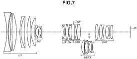
- Fig. 7 is a cross-sectional diagram illustrating a zoom lens according to the fourth exemplary embodiment that is set at a wide-angle end and in a state where a focus is placed on an object at infinity and an extender lens unit is removed.
- the zoom lens includes a first lens unit U1 that has positive refractive power, and does not move for zooming.
- a partial lens unit of the first lens unit U1 can move for focusing along an optical axis.
- the zoom lens further includes a second lens unit U2 (first variator) having negative refractive power.
- the second lens unit U2 moves (monotonically in one direction, for example) toward an image side along an optical axis for zooming from a wide-angle end to a telephoto end.
- the zoom lens further includes a third lens unit U3 (second variator) having negative refractive power.
- the third lens unit U3 moves (not monotonically in one direction, for example) along the optical axis for the zooming.
- the zoom lens further includes a fourth lens unit U4 (compensator) having positive refractive power.
- the fourth lens unit U4 moves (not monotonically in one direction, for example) along the optical axis for the zooming (correction (compensation) of a variation in an image plane position that is attributed to the zooming).
- the zoom lens further includes an aperture stop SP.
- the zoom lens further includes a lens unit UR1 (front relay lens unit; R1 lens unit) that does not move for zooming.
- the zoom lens further includes a lens unit UR2 (rear relay lens unit; R2 lens unit) that does not move for zooming.
- An image plane IP corresponds to a plane on which a light receiving surface of an image pickup element (photoelectric conversion element) that receives light of an image formed by the zoom lens is arranged.
- the zoom lens further includes an extender lens unit UEXT (EXT lens unit) to be inserted or removed into or from an optical path between the R1 lens unit and the R2 lens unit (typically, an optical path of afocal light) for changing a focal length range of the zoom lens.
- the first lens unit U1 includes first to 13th surfaces, and consists of a negative lens, a positive lens, a positive lens, a cemented lens of a negative lens and a positive lens, a positive lens, and a positive lens (seven lenses).
- the second lens unit U2 includes 14th to 20th surfaces, and consists of a negative lens, a cemented lens of a negative lens and a positive lens, and a negative lens (four lenses).
- the third lens unit U3 includes 21st to 23rd surfaces, and consists of a cemented lens of a positive lens and a negative lens (two lenses).
- the fourth lens unit U4 includes 24th to 28th surfaces, and consists of a positive lens, and a cemented lens of a negative lens and a positive lens (three lenses).
- the lens unit UR1 includes 30th to 34th surfaces, and consists of a cemented lens of a positive lens and a negative lens, and a positive lens (three lenses).
- the lens unit UR2 includes 35th to 44th surfaces, and consists of a positive lens, a cemented lens of a positive lens and a negative lens, a cemented lens of a positive lens and a negative lens, and a positive lens (six lenses).
- the extender lens unit UEXT is insertable and removable into and from an optical path between the 34th and 35th surfaces, and consists of a positive lens, a cemented lens of a negative lens and a positive lens, a cemented lens of a negative lens and a positive lens, and a negative lens (six lenses).
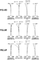
- Figs. 8A to 8F are aberration diagrams of the zoom lens according to the present exemplary embodiment (Numerical Example 4 corresponding to the present exemplary embodiment).
- Figs. 8A, 8B, and 8C illustrate longitudinal aberrations in a state where the zoom lens is set at the wide-angle end, in a state where a focal length is 177.67 mm, and in a state where the zoom lens is set at the telephoto end, respectively, in a state where a focus is placed on an object at infinity and the extender lens unit is removed.
- Figs. 8A, 8B, and 8C illustrate longitudinal aberrations in a state where the zoom lens is set at the wide-angle end, in a state where a focal length is 177.67 mm, and in a state where the zoom lens is set at the telephoto end, respectively, in a state where a focus is placed on an object at infinity and the extender lens unit is removed.
- 8D, 8E, and 8F illustrate longitudinal aberrations in a state where the zoom lens is set at the wide-angle end, in a state where a focal length is 247.80 mm, and in a state where the zoom lens is set at the telephoto end, respectively, in a state where a focus is placed on an object at infinity and the extender lens unit is inserted.
- a zoom ratio is 9.62 and magnification of the extender lens unit is 1.39.
- a half field angle at the wide-angle end is 29.6 degrees
- a half field angle at the telephoto end is 3.38 degrees
- a maximum image height is 14.8 mm.
- a maximum image height is increased to 21.64 mm.
- Numerical Example 4 can provide a zoom lens that satisfies all the inequalities (1) to (9) and incorporates an extender lens unit that is advantageous from the aspects of a large image circle, downsizing, and high optical performance over the entire zoom range.
- Fig. 9 is a cross-sectional diagram illustrating a zoom lens according to the fifth exemplary embodiment that is set at a wide-angle end and in a state where a focus is placed on an object at infinity and an extender lens unit is removed.
- the zoom lens illustrated in Fig. 9 includes a first lens unit U1 that has positive refractive power, and does not move for zooming.
- a partial lens unit of the first lens unit U1 can move for focusing along an optical axis.
- the zoom lens further includes a second lens unit U2 (first variator) having negative refractive power.
- the second lens unit U2 moves (monotonically in one direction, for example) toward an image side along an optical axis for zooming from a wide-angle end to a telephoto end.
- the zoom lens further includes a third lens unit U3 (second variator) having negative refractive power.
- the third lens unit U3 moves (not monotonically in one direction, for example) along the optical axis for the zooming.
- the zoom lens further includes a fourth lens unit U4 (third variator) having negative refractive power.
- the fourth lens unit U4 moves (not monotonically in one direction, for example) along the optical axis for the zooming.
- the zoom lens further includes a fifth lens unit U5 (compensator) having positive refractive power.
- the fifth lens unit U5 moves (not monotonically in one direction, for example) along the optical axis for the zooming (correction (compensation) of a variation in an image plane position that is attributed to the zooming).
- the zoom lens further includes an aperture stop SP.
- the zoom lens further includes a lens unit UR1 (front relay lens unit; R1 lens unit) that does not move for zooming.
- the zoom lens further includes a lens unit UR2 (rear relay lens unit; R2 lens unit) that does not move for zooming.
- An image plane IP corresponds to a plane on which a light receiving surface of an image pickup element (photoelectric conversion element) that receives light of an image formed by the zoom lens is arranged.
- the zoom lens further includes an extender lens unit UEXT (EXT lens unit) to be inserted or removed into or from an optical path between the R1 lens unit and the R2 lens unit (typically, an optical path of afocal light) for changing a focal length range of the zoom lens.
- EXT lens unit extender lens unit
- the first lens unit U1 includes first to 13th surfaces, and consists of a negative lens, a positive lens, a positive lens, a cemented lens of a negative lens and a positive lens, a positive lens, and a positive lens (seven lenses).
- the second lens unit U2 includes 14th to 18th surfaces, and consists of a negative lens, and a cemented lens of a negative lens and a positive lens (three lenses).
- the third lens unit U3 includes 19th to 20th surfaces, and consists of a single positive lens.
- the fourth lens unit U4 includes 21st to 23rd surfaces, and consists of a cemented lens of a positive lens and a negative lens (two lenses).
- the fifth lens unit U5 includes 24th to 28th surfaces, and consists of a positive lens, and a cemented lens of a negative lens and a positive lens (three lenses).
- the lens unit UR1 includes 30th to 34th surfaces, and consists of a cemented lens of a positive lens and a negative lens, and a positive lens (three lenses).
- the lens unit UR2 includes 35th to 44th surfaces, and consists of a positive lens, a cemented lens of a positive lens and a negative lens, a cemented lens of a positive lens and a negative lens, and a positive lens (six lenses).
- the extender lens unit UEXT is insertable and removable into and from an optical path between the 34th and 35th surfaces, and consists of a positive lens, a cemented lens of a negative lens and a positive lens, a cemented lens of a negative lens and a positive lens, and a negative lens (six lenses).
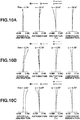
- Figs. 10A to 10F are aberration diagrams of the zoom lens according to the present exemplary embodiment (Numerical Example 5 corresponding to the present exemplary embodiment).
- Figs. 10A, 10B, and 10C illustrate longitudinal aberrations in a state where the zoom lens is set at the wide-angle end, in a state where a focal length is 177.00 mm, and in a state where the zoom lens is set at the telephoto end, respectively, in a state where a focus is placed on an object at infinity and the extender lens unit is removed.
- Figs. 10A to 10F are aberration diagrams of the zoom lens according to the present exemplary embodiment (Numerical Example 5 corresponding to the present exemplary embodiment).
- Figs. 10A, 10B, and 10C illustrate longitudinal aberrations in a state where the zoom lens is set at the wide-angle end, in a state where a focal length is 177.00 mm, and in a state where the zoom lens is set at the telephoto end, respectively, in
- 10D, 10E, and 10F illustrate longitudinal aberrations in a state where the zoom lens is set at the wide-angle end, in a state where a focal length is 260.19 mm, and in a state where the zoom lens is set at the telephoto end, respectively, in a state where a focus is placed on an object at infinity and the extender lens unit is inserted.
- a zoom ratio is 10.00 and magnification of the extender lens unit is 1.47.
- a half field angle at the wide-angle end is 30.6 degrees
- a half field angle at the telephoto end is 3.39 degrees
- a maximum image height is 14.8 mm.
- a maximum image height is increased to 21.64 mm.
- Numerical Example 5 can provide a zoom lens that satisfies all the inequalities (1) to (9) and incorporates an extender lens unit that is advantageous from the aspects of a large image circle, downsizing, and high optical performance over the entire zoom range.
- Fig. 11 is a cross-sectional diagram illustrating a zoom lens according to the sixth exemplary embodiment that is set at a wide-angle end and in a state where a focus is placed on an object at infinity and an extender lens unit is removed.
- the zoom lens illustrated in Fig. 11 includes a first lens unit U1 that has positive refractive power, and does not move for zooming.
- a partial lens unit of the first lens unit U1 can move for focusing along an optical axis.
- the zoom lens further includes a second lens unit U2 (first variator) having positive refractive power.
- the second lens unit U2 moves (monotonically in one direction, for example) toward an image side along an optical axis for zooming from a wide-angle end to a telephoto end.
- the zoom lens further includes a third lens unit U3 (second variator) having negative refractive power.
- the third lens unit U3 moves (not monotonically in one direction, for example) toward the image side along the optical axis for the zooming.
- the zoom lens further includes a fourth lens unit U4 (compensator) having positive refractive power.
- the fourth lens unit U4 moves (not monotonically in one direction, for example) along the optical axis for the zooming (correction (compensation) of a variation in an image plane position that is attributed to the zooming).
- the zoom lens further includes an aperture stop SP.
- the zoom lens further includes a lens unit UR1 (front relay lens unit; R1 lens unit) that does not move for zooming.
- the zoom lens further includes a lens unit UR2 (rear relay lens unit; R2 lens unit) that does not move for zooming.
- An image plane IP corresponds to a plane on which a light receiving surface of an image pickup element (photoelectric conversion element) that receives light of an image formed by the zoom lens is arranged.
- the zoom lens further includes an extender lens unit UEXT (EXT lens unit) to be inserted or removed into or from an optical path between the R1 lens unit and the R2 lens unit (typically, an optical path of afocal light) for changing a focal length range of the zoom lens.
- the first lens unit U1 includes first to 16th surfaces, and consists of a negative lens, a negative lens, a positive lens, a positive lens, a cemented lens of a positive lens and a negative lens, a cemented lens of a negative lens and a positive lens, and a positive lens (nine lenses).
- the second lens unit U2 includes 17th to 18th surfaces, and consists of a single positive lens.
- the third lens unit U3 includes 19th to 27th surfaces, and consists of a negative lens, a cemented lens of a positive lens and a negative lens, a negative lens, and a positive lens (five lenses).
- the fourth lens unit U4 includes 28th to 30th surfaces, and consists of a cemented lens of a negative lens and a positive lens (two lenses).
- the lens unit UR1 includes 32nd to 41st surfaces, and consists of a positive lens, a positive lens, a cemented lens of a positive lens and a negative lens, and a cemented lens of a positive lens and a negative lens (six lenses).
- the lens unit UR2 includes 42nd to 51st surfaces, and consists of a positive lens, a cemented lens of a positive lens and a negative lens, a cemented lens of a positive lens and a negative lens, and a positive lens (six lenses).
- the extender lens unit UEXT is insertable and removable into and from an optical path between the 41st and 42nd surfaces, and consists of a positive lens, a cemented lens of a negative lens and a positive lens, a cemented lens of a negative lens and a positive lens, and a negative lens (six lenses).
- Figs. 12A to 12F are aberration diagrams of the zoom lens according to the present exemplary embodiment (Numerical Example 6 corresponding to the present exemplary embodiment).
- Figs. 12A, 12B, and 12C illustrate longitudinal aberrations in a state where the zoom lens is set at the wide-angle end, in a state where a focal length is 59.71 mm, and in a state where the zoom lens is set at the telephoto end, respectively, in a state where a focus is placed on an object at infinity and the extender lens unit is removed.
- Figs. 12A to 12F are aberration diagrams of the zoom lens according to the present exemplary embodiment (Numerical Example 6 corresponding to the present exemplary embodiment).
- Figs. 12A, 12B, and 12C illustrate longitudinal aberrations in a state where the zoom lens is set at the wide-angle end, in a state where a focal length is 59.71 mm, and in a state where the zoom lens is set at the telephoto end, respectively
- 12D, 12E, and 12F illustrate longitudinal aberrations in a state where the zoom lens is set at the wide-angle end, in a state where a focal length is 89.57 mm, and in a state where the zoom lens is set at the telephoto end, respectively, in a state where a focus is placed on an object at infinity and the extender lens unit is inserted.
- a zoom ratio is 3.5 and magnification of the extender lens unit is 1.50.
- a half field angle at the wide-angle end is 36.5 degrees
- a half field angle at the telephoto end is 11.9 degrees
- a maximum image height is 14.8 mm.
- a maximum image height is increased to 21.64 mm.
- Numerical Example 6 can provide a zoom lens that satisfies all the inequalities (1) to (9) and incorporates an extender lens unit that is advantageous from the aspects of a large image circle, downsizing, and high optical performance over the entire zoom range.
- Fig. 13 is a diagram illustrating a configuration example of an imaging apparatus (e.g., television camera).
- a zoom lens 101 is any of the zoom lenses according to the first to sixth exemplary embodiments.
- the zoom lens 101 is detachable (replaceable) with respect to a camera main body (imaging apparatus main body) 124.
- An imaging apparatus 125 has a configuration in which the zoom lens 101 is attached to the camera main body 124.
- the zoom lens 101 includes a first lens unit F that does not move for zooming, a zooming lens unit LZ that moves for zooming, and relay lens units R1 and R2 for image formation.
- the first lens unit F includes a partial unit that moves for focusing.
- the zoom lens 101 includes a plurality of zooming lens units LZ that moves for zooming along trajectories different from each other, which is not illustrated in Fig. 13 .
- an aperture stop SP, the front relay lens unit R1, and the rear relay lens unit R2 are arranged in order.
- the zoom lens 101 further includes an extender lens unit IE insertable and removable into and from an optical path between the front relay lens unit R1 and the rear relay lens unit R2. By the insertion and removal of the extender lens unit IE, a focal length range of the zoom lens 101 can be changed.
- the imaging apparatus 125 further includes drive mechanisms 114 and 115 such as a helicoid and a cam for moving the first lens unit F and the zooming lens unit LZ, respectively, along the optical axis.
- Actuators (drive units) 116 to 118 drive the drive mechanisms 114 and 115 and the aperture stop SP, respectively.
- Detection units 119 to 121 such as an encoder, a potentiometer, and a photosensor detect a position on the optical axis of the first lens unit F, a position on the optical axis of the zooming lens unit LZ, and a stop diameter of the aperture stop SP, respectively.
- the camera main body 124 includes a glass block 109 such as an optical filter or a color separation optical system, and an image pickup element (photoelectric conversion element) 110 such as a charge-coupled device (CCD) sensor or a complementary metal-oxide semiconductor (CMOS) that receives light of an image formed by the zoom lens 101.
- Central processing units (CPUs) (processing units) 111 and 122 respectively control each component of the camera main body 124 and each component of the zoom lens 101.
- Example 1 Example 2 Example 3 Example 4 Example 5 Example 6 Inequality (1) (Def/Der)/ ⁇ e + (1 - few/feF) 1.36 1.25 1.70 1.55 1.20 1.71 Inequality (2) (le/Der)/ ⁇ e 1.04 0.90 0.89 0.82 0.95 0.86 Inequality (3) few/feF 0.52 0.71 0.24 0.49 0.73 0.23 Inequality (4) few/f1 0.45 0.53 0.60 0.45 0.56 0.22 Inequality (5) ⁇ z 0.58 0.51 0.43 0.58 0.56 0.41 Inequality (6) ⁇ e 1.39 1.57 1.66 1.39 1.47 1.50 Inequality (7) (R12 + R11)/(R12 - R11) 1.39 1.54 1.13 1.39 1.36 1.13 Inequality (8) hr/Der 0.38 0.35 0.42 0.46 0.38 0.44 Inequality (9) fe1/Der 3.59 2.41 2.34 2.92 2.55 2.76 few 36.39
Landscapes
- Physics & Mathematics (AREA)
- General Physics & Mathematics (AREA)
- Optics & Photonics (AREA)
- Nonlinear Science (AREA)
- Lenses (AREA)
- Studio Devices (AREA)
Abstract
Description
- The present invention relates to a zoom lens and an image pickup apparatus.
- For performing image capturing for a television program or a film (for example, outdoor image capturing of an animal or a human from a long distance), there is demand for a zoom lens having a high zooming ratio and high optical performance. Because such image capturing is often performed in a state where a camera is held on a shoulder, there is demand for a zoom lens advantageous also from the aspects of downsizing, weight saving, and portability.
- A teleconverter is used for changing a focal length range to a longer focal length range. Some zoom lenses for television cameras incorporate an extender (extender lens unit) insertable and removable into and from an afocal optical path in a relay lens unit. In the zoom lenses, even when a focal length range is switched by the insertion or removal of the extender, a total lens length and a back focus do not change.
- In the field of image capturing for films, a camera equipped with a large-sized image pickup element that is advantageous for image capturing under the environment with low illuminance can be used. Thus, there is an increasing demand for a zoom lens with a high zooming ratio that is excellent in portability and mobility while having an image circle corresponding to the large-sized image pickup element.
- Japanese Patent Laid-Open No.
2016-45310 - If a large-sized image pickup element is employed by the insertion of the incorporated extender into an optical path as in Japanese Patent Laid-Open No.
2016-45310 - An aspect of embodiments provides, for example, a zoom lens, including an extender lens unit therein, beneficial in a large image circle, small size, and high optical performance.
- The present invention in its first aspect provides a zoom lens as specified in
claims 1 to 8. - The present invention in its second aspect provides an image pickup apparatus as specified in
claim 9. - Further features of the present invention will become apparent from the following description of exemplary embodiments with reference to the attached drawings.
-
-
Fig. 1 is a cross-sectional diagram illustrating a zoom lens according to a first exemplary embodiment that is set at a wide-angle end and in a state where a focus is placed on an object at infinity. -
Figs. 2A to 2F are aberration diagrams of the zoom lens according to the first exemplary embodiment. -
Fig. 3 is a cross-sectional diagram illustrating a zoom lens according to a second exemplary embodiment that is set at a wide-angle end and in a state where a focus is placed on an object at infinity. -
Figs. 4A to 4F are aberration diagrams of the zoom lens according to the second exemplary embodiment. -
Fig. 5 is a cross-sectional diagram illustrating a zoom lens according to a third exemplary embodiment that is set at a wide-angle end and in a state where a focus is placed on an object at infinity. -
Figs. 6A to 6F are aberration diagrams of the zoom lens according to the third exemplary embodiment. -
Fig. 7 is a cross-sectional diagram illustrating a zoom lens according to a fourth exemplary embodiment that is set at a wide-angle end and in a state where a focus is placed on an object at infinity. -
Figs. 8A to 8F are aberration diagrams of the zoom lens according to the fourth exemplary embodiment. -
Fig. 9 is a cross-sectional diagram illustrating a zoom lens according to a fifth exemplary embodiment that is set at a wide-angle end and in a state where a focus is placed on an object at infinity. -
Figs. 10A to 10F are aberration diagrams of the zoom lens according to the fifth exemplary embodiment. -
Fig. 11 is a cross-sectional diagram illustrating a zoom lens according to a sixth exemplary embodiment that is set at a wide-angle end and in a state where a focus is placed on an object at infinity. -
Figs. 12A to 12F are aberration diagrams of the zoom lens according to the sixth exemplary embodiment. -
Fig. 13 is a diagram illustrating a configuration example of an imaging apparatus. - Hereinafter, exemplary embodiments of the present invention will be described with reference to the attached drawings. In all the drawings for describing the exemplary embodiments, as a general rule (unless otherwise stated), the same members are assigned the same reference numerals, and the redundant descriptions thereof will be omitted. Each of the embodiments of the present invention described below can be implemented solely or as a combination of a plurality of the embodiments or features thereof where necessary or where the combination of elements or features from individual embodiments in a single embodiment is beneficial.
-
Fig. 1 is a cross-sectional diagram illustrating a zoom lens according to the first exemplary embodiment that is set at a wide-angle end and in a state where a focus is placed on an object at infinity and an extender lens unit is removed. The zoom lens illustrated inFig. 1 includes a first lens unit U1 that has positive refractive power and does not move for zooming. A partial lens unit of the first lens unit U1 can move for focusing along an optical axis. The zoom lens further includes a second lens unit U2 (first variator) having negative refractive power. The second lens unit U2 moves (monotonically in one direction, for example) toward an image side along an optical axis for zooming from a wide-angle end (short focal length end) to a telephoto end (long focal length end). The zoom lens further includes a third lens unit U3 (second variator) having negative refractive power. The third lens unit U3 moves (not monotonically in one direction, for example) along the optical axis for the zooming. The zoom lens further includes a fourth lens unit U4 (compensator) having positive refractive power. The fourth lens unit U4 moves (not monotonically in one direction, for example) along the optical axis for the zooming (correction (compensation) of a variation in an image plane position that is attributed to the zooming). The zoom lens further includes an aperture stop SP. The zoom lens further includes a lens unit UR1 (front relay lens unit; R1 lens unit) that does not move for zooming. The zoom lens further includes a lens unit UR2 (rear relay lens unit; R2 lens unit) that does not move for zooming. An image plane IP corresponds to a plane on which a light receiving surface of an image pickup element (photoelectric conversion element) that receives light of an image formed by the zoom lens is arranged. The zoom lens further includes an extender lens unit UEXT (EXT lens unit) to be inserted or removed into or from an optical path between the R1 lens unit and the R2 lens unit (typically, an optical path of afocal light) for changing a focal length range of the zoom lens. - The configuration of each lens unit will now be described. Hereinafter, in each lens unit, lenses are arranged in order from an object side to an image side. The first lens unit U1 includes first to 13th surfaces, and consists of a negative lens, a positive lens, a positive lens, a cemented lens of a negative lens and a positive lens, a positive lens, and a positive lens (seven lenses). The second lens unit U2 includes 14th to 20th surfaces, and consists of a negative lens, a cemented lens of a negative lens and a positive lens, and a negative lens (four lenses). The third lens unit U3 includes 21st to 23rd surfaces, and consists of a cemented lens of a positive lens and a negative lens (two lenses). The fourth lens unit U4 includes 24th to 28th surfaces, and consists of a positive lens, and a cemented lens of a negative lens and a positive lens (three lenses). The lens unit UR1 includes 30th to 34th surfaces, and consists of a cemented lens of a positive lens and a negative lens, and a positive lens (three lenses). The lens unit UR2 includes 35th to 44th surfaces, and consists of a positive lens, a cemented lens of a positive lens and a negative lens, a cemented lens of a positive lens and a negative lens, and a positive lens (six lenses). The extender lens unit UEXT is insertable and removable into and from an optical path between the 34th and 35th surfaces, and consists of a positive lens, a cemented lens of a negative lens and a positive lens, a cemented lens of a negative lens and a positive lens, and a negative lens (six lenses).
-
Figs. 2A to 2F are aberration diagrams of the zoom lens according to the present exemplary embodiment (Numerical Example 1 corresponding to the present exemplary embodiment).Figs. 2A, 2B, and 2C illustrate longitudinal aberrations in a state where the zoom lens is set at the wide-angle end, in a state where a focal length is 177.00 mm, and in a state where the zoom lens is set at the telephoto end, respectively, in a state where a focus is placed on an object at infinity and the extender lens unit is removed.Figs. 2D, 2E, and 2F illustrate longitudinal aberrations in a state where the zoom lens is set at the wide-angle end, in a state where a focal length is 260.19 mm, and in a state where the zoom lens is set at the telephoto end, respectively, in a state where a focus is placed on an object at infinity and the extender lens unit is inserted. - In the longitudinal aberration diagrams, spherical aberration is aberration with respect to an e-line (solid line) and a g-line (dotted line). Astigmatism is aberration on a meridional image plane (dotted line) and a sagittal image plane (solid line) with respect to the e-line. Magnification chromatic aberration is aberration with respect to the g-line (dotted line). Fno denotes an F-number and ω denotes a half field angle. A scale in the longitudinal aberration diagrams defines that, in a state where the extender lens unit is removed, spherical aberration is 0.4 mm, astigmatism is 0.4 mm, distortion is 10%, and magnification chromatic aberration is 0.1 mm. The same scale defines that, in a state where the extender lens unit is inserted, spherical aberration is 0.8 mm, astigmatism is 0.8 mm, distortion is 10%, and magnification chromatic aberration is 0.1 mm. The wide-angle end and the telephoto end correspond to the ends of a movable range of the second lens unit U2. Graph legends in longitudinal aberration diagrams in other examples are given similarly to the graph legends in these longitudinal aberration diagrams.
- In the present exemplary embodiment, a zoom ratio is 9.62 and magnification of the extender lens unit is 1.47. In a state where the extender lens unit is removed, a half field angle at the wide-angle end is 29.7 degrees, a half field angle at the telephoto end is 3.39 degrees, and a maximum image height is 14.8 mm. In a state where the extender lens unit is inserted, a maximum image height is increased to 21.64 mm.
- An extender lens unit incorporated in a zoom lens supporting a large-sized image pickup element such as a zoom lens used for film image capturing needs to ensure a light amount up to the end of the image pickup element. It is therefore necessary to determine an effective diameter of a lens closest to an image based on an off-axis ray, and a ratio between an effective diameter of a lens closest to an object and an effective diameter of a lens closest to an image becomes smaller than enlargement magnification (transverse magnification) of the extender lens unit. Because an effective diameter of a lens closest to the image in a lens unit closest to the image (rear relay lens unit; R2 lens unit) also needs to be determined based on an off-axis ray, an effective diameter of a lens on the image side of the extender lens unit increases, and the zoom lens upsizes. The zoom lens according to the present exemplary embodiment blunts an incident angle of an off-axis ray to the extender lens unit by causing a converging on-axis ray to enter the extender lens unit. Furthermore, an effective diameter of a lens of the extender lens unit that is closest to the image is appropriately set. With such a configuration, the present exemplary embodiment can provide a zoom lens incorporating an extender lens unit that is advantageous from the aspects of a large image circle, downsizing, and high optical performance.
- The zoom lens according to the present exemplary embodiment includes, in order from an object side to an image side, the first lens unit that does not move for zooming, and a plurality of zooming lens units that moves for zooming. The zoom lens further includes the R1 lens unit that does not move for zooming, the extender lens unit insertable and removable into and from an optical path, and the R2 lens unit that does not move for zooming. The zoom lens according to the present exemplary embodiment satisfies the following inequalities:


- An effective diameter of the zoom lens on each surface is defined as a double of a maximum light ray height on the corresponding surface. The maximum light ray height in a lens or a lens unit is assumed to be the maximum light ray height among a plurality of maximum light ray heights on a plurality of surfaces included in the lens or the lens unit. Inequality (1) defines a relationship between the following three amounts a to c.
- a) A ratio between the effective diameter of the lens of the extender lens unit that is closest to the object and the effective diameter of the lens of the extender lens unit that is closest to the image
- b) Transverse magnification of the extender lens unit
- c) A ratio between the focal length of the zoom lens in a state where the extender lens unit is inserted and the zoom lens is set at the wide-angle end, and a combined focal length of lens units of the zoom lens that are on the object side of the extender lens unit
- At this time, the amount c) defined as (few/feF) indicates an incident angle of a paraxial on-axis ray to the extender lens unit, and when the paraxial on-axis ray is parallel to the optical axis, (few/feF) becomes 0. The more the paraxial on-axis ray converges, the more (few/feF) becomes a value larger than 0. In other words, Inequality (1) defines a relationship between the incident angle of the paraxial on-axis ray to the extender lens unit and an effective diameter of the extender lens unit. The converging paraxial on-axis ray means that an incident angle of an off-axis ray becomes smaller. If a value of Inequality (1) exceeds an upper limit, a diameter of a lens on the image side of the extender lens unit becomes too large, which is disadvantageous from the aspect of downsizing of the zoom lens. If a value of Inequality (1) falls below a lower limit, although the zoom lens becomes advantageous from the aspect of downsizing of the zoom lens, refractive power of each lens of the extender lens unit becomes too large, which is disadvantageous from the aspect of aberration correction of the zoom lens.
- The zoom lens more preferably satisfies the following inequality:

- Inequality (2) defines a relationship between the following two amounts d and e.
- d) A ratio between an overall thickness of the extender lens unit and an effective diameter of the lens of the extender lens unit that is closest to the image
- e) Transverse magnification of the extender lens unit
- By satisfying Inequality (2), the zoom lens becomes advantageous from the aspects of downsizing of the extender lens unit and high optical performance over the entire zoom range. If a value of Inequality (2) exceeds an upper limit, the overall thickness of the extender lens unit becomes too large and refractive power of each lens becomes too small, which is advantageous from the aspect of aberration correction, but the zoom lens becomes disadvantageous from the aspect of downsizing of the extender lens unit. If a value of Inequality (2) falls below a lower limit, although the zoom lens becomes advantageous from the aspect of downsizing of the extender lens unit, refractive power of each lens becomes too large, which is disadvantageous from the aspect of aberration correction.
- The zoom lens more preferably satisfies the following inequality:

- By satisfying Inequalities (1) and (2), the zoom lens according to the present exemplary embodiment can provide a zoom lens incorporating an extender lens unit that is advantageous from the aspects of a large image circle, downsizing, and high optical performance.
- The zoom lens according to the present exemplary embodiment further satisfies the following inequality (3):

- By satisfying Inequality (3), the zoom lens becomes advantageous from the aspects of downsizing and high optical performance over the entire zoom range. If a value of Inequality (3) exceeds an upper limit, an incident angle of an on-axis ray to the extender lens unit becomes too large (an incident angle of an off-axis ray becomes too small), which is advantageous from the aspect of downsizing of the zoom lens. Although the zoom lens becomes advantageous, refractive power of each lens of the extender lens unit becomes too large, which is disadvantageous from the aspect of aberration correction of the zoom lens. If a value of Inequality (3) falls below a lower limit, an incident angle of an on-axis ray to the extender lens unit becomes close to parallel to the optical axis (an incident angle of an off-axis ray becomes too large), and an effective diameter of a lens on the image side of the extender lens unit becomes too large, which is disadvantageous from the aspect of downsizing of the zoom lens.
- The zoom lens more preferably satisfies the following inequality:

- The zoom lens according to the present exemplary embodiment further satisfies the following inequality (4)

- By satisfying Inequality (4), the zoom lens becomes advantageous from the aspects of a sufficient light amount in a large image circle, high optical performance, and downsizing. If a value of Inequality (4) exceeds an upper limit, although the zoom lens becomes advantageous from the aspect of a light amount, the focal length f1 becomes relatively small. The zoom lens therefore becomes disadvantageous from the aspect of aberration correction of the zoom lens. If a value of Inequality (4) falls below a lower limit, although the zoom lens becomes advantageous from the aspect of aberration correction of the zoom lens, the zoom lens becomes disadvantageous from the aspect of a light amount. If a lens diameter is increased for ensuring a light amount, the zoom lens becomes disadvantageous from the aspect of downsizing.
- The zoom lens more preferably satisfies the following inequality:

- The zoom lens according to the present exemplary embodiment further satisfies the following inequality (5):

- By satisfying Inequality (5), the zoom lens becomes advantageous from the aspects of high optical performance over the entire zoom range and downsizing. If a value of Inequality (5) exceeds an upper limit, aberration is excessively augmented due to too large transverse magnification βz, which is disadvantageous from the aspect of aberration correction of the zoom lens. If a value of Inequality (5) falls below a lower limit, the transverse magnification βz becomes small, and a movement amount of a lens unit having the transverse magnification βz increases for obtaining a high zooming ratio. The total lens length therefore increases, which is disadvantageous from the aspect of downsizing.
- The zoom lens more preferably satisfies the following inequality:

- The zoom lens according to the present exemplary embodiment further satisfies the following inequality (6):

- By satisfying Inequality (6), the zoom lens becomes advantageous from the aspects of high optical performance over the entire zoom range and downsizing. If a value of Inequality (6) exceeds an upper limit, for obtaining high optical performance, the extender lens unit becomes too large in the direction of the optical axis. If a value of Inequality (6) falls below a lower limit, although the zoom range becomes advantageous from the aspect of aberration correction of the zoom lens, a lens diameter of the extender lens unit becomes too large.
- The zoom lens more preferably satisfies the following inequality:

- The zoom lens according to the present exemplary embodiment satisfies the following inequality (7):

- Satisfying Inequality (7) means that the single lens is a convex meniscus lens. If a value of Inequality (7) exceeds an upper limit, although the zoom lens becomes advantageous from the aspect of aberration correction of the zoom lens, the zoom lens becomes disadvantageous from the aspect of downsizing of the extender lens unit. If a value of Inequality (7) falls below a lower limit, because the single lens becomes a biconvex lens, although the zoom lens becomes advantageous from the aspect of downsizing, the zoom lens becomes disadvantageous from the aspect of aberration correction of the zoom lens.
- The zoom lens more preferably satisfies the following inequality:

- The zoom lens according to the present exemplary embodiment further satisfies the following inequality (8):

- By satisfying Inequality (8), the zoom lens becomes advantageous from the aspects of a light amount in an image circle peripheral portion and downsizing of the extender lens unit. If a value of Inequality (8) exceeds an upper limit, although the zoom lens becomes advantageous from the aspect of downsizing of the extender lens unit, the zoom lens becomes disadvantageous from the aspect of a light amount in an image circle peripheral portion. If a value of Inequality (8) falls below a lower limit, although the zoom lens becomes advantageous from the aspect of a light amount in an image circle peripheral portion, the zoom lens becomes disadvantageous from the aspect of downsizing of the zoom lens.
- The zoom lens more preferably satisfies the following inequality:

- The zoom lens according to the present exemplary embodiment further satisfies the following inequality (9):

- By satisfying Inequality (9), the zoom lens becomes advantageous from the aspects of downsizing of the extender lens unit, a light amount in an image circle peripheral portion, and high optical performance over the entire zoom range. If a value of Inequality (9) exceeds an upper limit, although the zoom lens becomes advantageous from the aspect of aberration correction of the zoom lens because refractive power of the lens becomes too small, the zoom lens becomes disadvantageous from the aspect of downsizing of the extender lens unit, and becomes disadvantageous also from the aspect of a light amount in an image circle peripheral portion. If a value of Inequality (9) falls below a lower limit, although the zoom lens becomes advantageous from the aspects of downsizing of the extender lens unit and a light amount in an image circle peripheral portion, the zoom lens becomes disadvantageous from the aspect of aberration correction of the zoom lens because refractive power of the lens becomes too large.
- The zoom lens more preferably satisfies the following inequality:

- Numerical value data of Numerical Example 1 corresponding to the first exemplary embodiment will be described below. In each numerical example, r is a curvature radius of each surface, d is each surface interval, and vd is an Abbe number. In addition, nd is an absolute refractive index at 1 atm (atmospheric pressure) with respect to a d-line of Fraunhofer lines. Ng, NF, Nd, and NC are refractive indices with respect to a g-line, an F-line, a d-line, and a Cline of Fraunhofer lines, respectively. The definitions of the Abbe number vd and a partial dispersion ratio θgf are similar to generally-used definitions. More specifically, the Abbe number vd and the partial dispersion ratio θgf are represented as follows:


- An aspherical shape is represented assuming that an X-axis is set to the direction of the optical axis, an H-axis is set to a direction orthogonal to the direction of the optical axis, and a travelling direction of light is set as a positive direction. The aspherical shape is represented by the following formula:

- A focal length, an F-number, and a field angle indicate values in a state where a focus is placed on an object at infinity. BF is a distance from a final lens surface to an image plane. In addition, "e-Z" means "× 10-Z".
- Table 1 described below lists values in the inequalities in Numerical Example 1. Numerical Example 1 can provide a zoom lens that satisfies all the inequalities (1) to (9) and incorporates an extender lens unit that is advantageous from the aspects of a large image circle, downsizing, and high optical performance over the entire zoom range.
-
Fig. 3 is a cross-sectional diagram illustrating a zoom lens according to the second exemplary embodiment that is set at a wide-angle end and in a state where a focus is placed on an object at infinity and an extender lens unit is removed. The zoom lens illustrated inFig. 3 includes a first lens unit U1 that has positive refractive power, and does not move for zooming. A partial lens unit of the first lens unit U1 can move for focusing along an optical axis. The zoom lens further includes a second lens unit U2 (first variator) having negative refractive power. The second lens unit U2 moves (monotonically in one direction, for example) toward an image side along an optical axis for zooming from a wide-angle end to a telephoto end. The zoom lens further includes a third lens unit U3 (second variator) having negative refractive power. The third lens unit U3 moves (not monotonically in one direction, for example) along the optical axis for the zooming. The zoom lens further includes a fourth lens unit U4 (compensator) having positive refractive power. The fourth lens unit U4 moves (not monotonically in one direction, for example) along the optical axis for the zooming (correction (compensation) of a variation in an image plane position that is attributed to the zooming). The zoom lens further includes an aperture stop SP. The zoom lens further includes a lens unit UR1 (front relay lens unit; R1 lens unit) that does not move for zooming. The zoom lens further includes a lens unit UR2 (rear relay lens unit; R2 lens unit) that does not move for zooming. An image plane IP corresponds to a plane on which a light receiving surface of an image pickup element (photoelectric conversion element) that receives light of an image formed by the zoom lens is arranged. The zoom lens further includes an extender lens unit UEXT (EXT lens unit) to be inserted or removed into or from an optical path between the R1 lens unit and the R2 lens unit (typically, an optical path of afocal light) for changing a focal length range of the zoom lens. - The configuration of each lens unit will now be described. Hereinafter, in each lens unit, lenses are arranged in order from an object side to an image side. The first lens unit U1 includes first to 13th surfaces, and consists of a negative lens, a positive lens, a positive lens, a cemented lens of a negative lens and a positive lens, a positive lens, and a positive lens (seven lenses). The second lens unit U2 includes 14th to 20th surfaces, and consists of a negative lens, a cemented lens of a negative lens and a positive lens, and a negative lens (four lenses). The third lens unit U3 includes 21st to 23rd surfaces, and consists of a cemented lens of a negative lens and a positive lens (two lenses). The fourth lens unit U4 includes 24th to 28th surfaces, and consists of a positive lens, and a cemented lens of a negative lens and a positive lens (three lenses). The lens unit UR1 includes 30th to 34th surfaces, and consists of a cemented lens of a positive lens and a negative lens, and a positive lens (three lenses). The lens unit UR2 includes 35th to 44th surfaces, and consists of a positive lens, a cemented lens of a positive lens and a negative lens, a cemented lens of a positive lens and a negative lens, and a positive lens (six lenses). The extender lens unit UEXT is insertable and removable into and from an optical path between the 34th and 35th surfaces, and consists of a positive lens, a cemented lens of a negative lens and a positive lens, a cemented lens of a negative lens and a positive lens, and a negative lens (six lenses).
-
Figs. 4A to 4F are aberration diagrams of the zoom lens according to the present exemplary embodiment (Numerical Example 2 corresponding to the present exemplary embodiment).Figs. 4A, 4B, and 4C illustrate longitudinal aberrations in a state where the zoom lens is set at the wide-angle end, in a state where a focal length is 179.00 mm, and in a state where the zoom lens is set at the telephoto end, respectively, in a state where a focus is placed on an object at infinity and the extender lens unit is removed.Figs. 4D, 4E, and 4F illustrate longitudinal aberrations in a state where the zoom lens is set at the wide-angle end, in a state where a focal length is 281.03 mm, and in a state where the zoom lens is set at the telephoto end, respectively, in a state where a focus is placed on an object at infinity and the extender lens unit is inserted. - In the present exemplary embodiment, a zoom ratio is 9.62 and magnification of the extender lens unit is 1.57. In a state where the extender lens unit is removed, a half field angle at the wide-angle end is 29.7 degrees, a half field angle at the telephoto end is 3.39 degrees, and a maximum image height is 14.8 mm. In a state where the extender lens unit is inserted, a maximum image height is increased to 23.20 mm.
- Table 1 described below lists values in the inequalities in Numerical Example 2. Numerical Example 2 can provide a zoom lens that satisfies all the inequalities (1) to (9) and incorporates an extender lens unit that is advantageous from the aspects of a large image circle, downsizing, and high optical performance over the entire zoom range.
-
Fig. 5 is a cross-sectional diagram illustrating a zoom lens according to the third exemplary embodiment that is set at a wide-angle end and in a state where a focus is placed on an object at infinity and an extender lens unit is removed. The zoom lens includes a first lens unit U1 that has positive refractive power, and does not move for zooming. A partial lens unit of the first lens unit U1 can move for focusing along an optical axis. The zoom lens further includes a second lens unit U2 (variator) having negative refractive power. The second lens unit U2 moves (monotonically in one direction, for example) toward an image side along an optical axis for zooming from a wide-angle end to a telephoto end. The zoom lens further includes a third lens unit U3 (compensator) having negative refractive power. The third lens unit U3 moves (not monotonically in one direction, for example) along the optical axis for the zooming (correction (compensation) of a variation in an image plane position that is attributed to the zooming). The zoom lens further includes an aperture stop SP. The zoom lens further includes a lens unit UR1 (front relay lens unit; R1 lens unit) that does not move for zooming. The zoom lens further includes a lens unit UR2 (rear relay lens unit; R2 lens unit) that does not move for zooming. An image plane IP corresponds to a plane on which a light receiving surface of an image pickup element (photoelectric conversion element) that receives light of an image formed by the zoom lens is arranged. The zoom lens further includes an extender lens unit UEXT (EXT lens unit) to be inserted or removed into or from an optical path between the R1 lens unit and the R2 lens unit (typically, an optical path of afocal light) for changing a focal length range of the zoom lens. - The configuration of each lens unit will now be described. Hereinafter, in each lens unit, lenses are arranged in order from an object side to an image side. The first lens unit U1 includes first to 18th surfaces, and consists of a negative lens, a negative lens, a positive lens, a positive lens, a cemented lens of a positive lens and a negative lens, a cemented lens of a negative lens and a positive lens, a positive lens, and a positive lens (ten lenses). The second lens unit U2 includes 19th to 27th surfaces, and consists of a negative lens, a cemented lens of a positive lens and a negative lens, a negative lens, and a positive lens (five lenses). The third lens unit U3 includes 28th to 30th surfaces, and consists of a cemented lens of a negative lens and a positive lens (two lenses). The lens unit UR1 includes 32nd to 41st surfaces, and consists of a positive lens, a positive lens, a cemented lens of a positive lens and a negative lens, and a cemented lens of a positive lens and a negative lens (six lenses). The lens unit UR2 includes 42nd to 51st surfaces, and consists of a positive lens, a cemented lens of a positive lens and a negative lens, a cemented lens of a positive lens and a negative lens, and a positive lens (six lenses). The extender lens unit UEXT is insertable and removable into and from an optical path between the 41st and 42nd surfaces, and consists of a positive lens, a cemented lens of a negative lens and a positive lens, a cemented lens of a negative lens and a positive lens, and a negative lens (six lenses).
-
Figs. 6A to 6F are aberration diagrams of the zoom lens according to the present exemplary embodiment (Numerical Example 3 corresponding to the present exemplary embodiment).Figs. 6A, 6B, and 6C illustrate longitudinal aberrations in a state where the zoom lens is set at the wide-angle end, in a state where a focal length is 106.20 mm, and in a state where the zoom lens is set at the telephoto end, respectively, in a state where a focus is placed on an object at infinity and the extender lens unit is removed.Figs. 6D, 6E, and 6F illustrate longitudinal aberrations in a state where the zoom lens is set at the wide-angle end, in a state where a focal length is 176.00 mm, and in a state where the zoom lens is set at the telephoto end, respectively, in a state where a focus is placed on an object at infinity and the extender lens unit is inserted. - In the present exemplary embodiment, a zoom ratio is 8.00 and magnification of the extender lens unit is 1.66. In a state where the extender lens unit is removed, a half field angle at the wide-angle end is 37.5 degrees, a half field angle at the telephoto end is 5.47 degrees, and a maximum image height is 14.8 mm. In a state where the extender lens unit is inserted, a maximum image height is increased to 21.64 mm.
- Table 1 described below lists values in the inequalities in Numerical Example 3. Numerical Example 3 can provide a zoom lens that satisfies all the inequalities (1) to (9) and incorporates an extender lens unit that is advantageous from the aspects of a large image circle, downsizing, and high optical performance over the entire zoom range.
-
Fig. 7 is a cross-sectional diagram illustrating a zoom lens according to the fourth exemplary embodiment that is set at a wide-angle end and in a state where a focus is placed on an object at infinity and an extender lens unit is removed. The zoom lens includes a first lens unit U1 that has positive refractive power, and does not move for zooming. A partial lens unit of the first lens unit U1 can move for focusing along an optical axis. The zoom lens further includes a second lens unit U2 (first variator) having negative refractive power. The second lens unit U2 moves (monotonically in one direction, for example) toward an image side along an optical axis for zooming from a wide-angle end to a telephoto end. The zoom lens further includes a third lens unit U3 (second variator) having negative refractive power. The third lens unit U3 moves (not monotonically in one direction, for example) along the optical axis for the zooming. The zoom lens further includes a fourth lens unit U4 (compensator) having positive refractive power. The fourth lens unit U4 moves (not monotonically in one direction, for example) along the optical axis for the zooming (correction (compensation) of a variation in an image plane position that is attributed to the zooming). The zoom lens further includes an aperture stop SP. The zoom lens further includes a lens unit UR1 (front relay lens unit; R1 lens unit) that does not move for zooming. The zoom lens further includes a lens unit UR2 (rear relay lens unit; R2 lens unit) that does not move for zooming. An image plane IP corresponds to a plane on which a light receiving surface of an image pickup element (photoelectric conversion element) that receives light of an image formed by the zoom lens is arranged. The zoom lens further includes an extender lens unit UEXT (EXT lens unit) to be inserted or removed into or from an optical path between the R1 lens unit and the R2 lens unit (typically, an optical path of afocal light) for changing a focal length range of the zoom lens. - The configuration of each lens unit will now be described. Hereinafter, in each lens unit, lenses are arranged in order from an object side to an image side. The first lens unit U1 includes first to 13th surfaces, and consists of a negative lens, a positive lens, a positive lens, a cemented lens of a negative lens and a positive lens, a positive lens, and a positive lens (seven lenses). The second lens unit U2 includes 14th to 20th surfaces, and consists of a negative lens, a cemented lens of a negative lens and a positive lens, and a negative lens (four lenses). The third lens unit U3 includes 21st to 23rd surfaces, and consists of a cemented lens of a positive lens and a negative lens (two lenses). The fourth lens unit U4 includes 24th to 28th surfaces, and consists of a positive lens, and a cemented lens of a negative lens and a positive lens (three lenses). The lens unit UR1 includes 30th to 34th surfaces, and consists of a cemented lens of a positive lens and a negative lens, and a positive lens (three lenses). The lens unit UR2 includes 35th to 44th surfaces, and consists of a positive lens, a cemented lens of a positive lens and a negative lens, a cemented lens of a positive lens and a negative lens, and a positive lens (six lenses). The extender lens unit UEXT is insertable and removable into and from an optical path between the 34th and 35th surfaces, and consists of a positive lens, a cemented lens of a negative lens and a positive lens, a cemented lens of a negative lens and a positive lens, and a negative lens (six lenses).
-
Figs. 8A to 8F are aberration diagrams of the zoom lens according to the present exemplary embodiment (Numerical Example 4 corresponding to the present exemplary embodiment).Figs. 8A, 8B, and 8C illustrate longitudinal aberrations in a state where the zoom lens is set at the wide-angle end, in a state where a focal length is 177.67 mm, and in a state where the zoom lens is set at the telephoto end, respectively, in a state where a focus is placed on an object at infinity and the extender lens unit is removed.Figs. 8D, 8E, and 8F illustrate longitudinal aberrations in a state where the zoom lens is set at the wide-angle end, in a state where a focal length is 247.80 mm, and in a state where the zoom lens is set at the telephoto end, respectively, in a state where a focus is placed on an object at infinity and the extender lens unit is inserted. - In the present exemplary embodiment, a zoom ratio is 9.62 and magnification of the extender lens unit is 1.39. In a state where the extender lens unit is removed, a half field angle at the wide-angle end is 29.6 degrees, a half field angle at the telephoto end is 3.38 degrees, and a maximum image height is 14.8 mm. In a state where the extender lens unit is inserted, a maximum image height is increased to 21.64 mm.
- Table 1 described below lists values in the inequalities in Numerical Example 4. Numerical Example 4 can provide a zoom lens that satisfies all the inequalities (1) to (9) and incorporates an extender lens unit that is advantageous from the aspects of a large image circle, downsizing, and high optical performance over the entire zoom range.
-
Fig. 9 is a cross-sectional diagram illustrating a zoom lens according to the fifth exemplary embodiment that is set at a wide-angle end and in a state where a focus is placed on an object at infinity and an extender lens unit is removed. The zoom lens illustrated inFig. 9 includes a first lens unit U1 that has positive refractive power, and does not move for zooming. A partial lens unit of the first lens unit U1 can move for focusing along an optical axis. The zoom lens further includes a second lens unit U2 (first variator) having negative refractive power. The second lens unit U2 moves (monotonically in one direction, for example) toward an image side along an optical axis for zooming from a wide-angle end to a telephoto end. The zoom lens further includes a third lens unit U3 (second variator) having negative refractive power. The third lens unit U3 moves (not monotonically in one direction, for example) along the optical axis for the zooming. The zoom lens further includes a fourth lens unit U4 (third variator) having negative refractive power. The fourth lens unit U4 moves (not monotonically in one direction, for example) along the optical axis for the zooming. The zoom lens further includes a fifth lens unit U5 (compensator) having positive refractive power. The fifth lens unit U5 moves (not monotonically in one direction, for example) along the optical axis for the zooming (correction (compensation) of a variation in an image plane position that is attributed to the zooming). The zoom lens further includes an aperture stop SP. The zoom lens further includes a lens unit UR1 (front relay lens unit; R1 lens unit) that does not move for zooming. The zoom lens further includes a lens unit UR2 (rear relay lens unit; R2 lens unit) that does not move for zooming. An image plane IP corresponds to a plane on which a light receiving surface of an image pickup element (photoelectric conversion element) that receives light of an image formed by the zoom lens is arranged. The zoom lens further includes an extender lens unit UEXT (EXT lens unit) to be inserted or removed into or from an optical path between the R1 lens unit and the R2 lens unit (typically, an optical path of afocal light) for changing a focal length range of the zoom lens. - The configuration of each lens unit will now be described. Hereinafter, in each lens unit, lenses are arranged in order from an object side to an image side. The first lens unit U1 includes first to 13th surfaces, and consists of a negative lens, a positive lens, a positive lens, a cemented lens of a negative lens and a positive lens, a positive lens, and a positive lens (seven lenses). The second lens unit U2 includes 14th to 18th surfaces, and consists of a negative lens, and a cemented lens of a negative lens and a positive lens (three lenses). The third lens unit U3 includes 19th to 20th surfaces, and consists of a single positive lens. The fourth lens unit U4 includes 21st to 23rd surfaces, and consists of a cemented lens of a positive lens and a negative lens (two lenses). The fifth lens unit U5 includes 24th to 28th surfaces, and consists of a positive lens, and a cemented lens of a negative lens and a positive lens (three lenses). The lens unit UR1 includes 30th to 34th surfaces, and consists of a cemented lens of a positive lens and a negative lens, and a positive lens (three lenses). The lens unit UR2 includes 35th to 44th surfaces, and consists of a positive lens, a cemented lens of a positive lens and a negative lens, a cemented lens of a positive lens and a negative lens, and a positive lens (six lenses). The extender lens unit UEXT is insertable and removable into and from an optical path between the 34th and 35th surfaces, and consists of a positive lens, a cemented lens of a negative lens and a positive lens, a cemented lens of a negative lens and a positive lens, and a negative lens (six lenses).
-
Figs. 10A to 10F are aberration diagrams of the zoom lens according to the present exemplary embodiment (Numerical Example 5 corresponding to the present exemplary embodiment).Figs. 10A, 10B, and 10C illustrate longitudinal aberrations in a state where the zoom lens is set at the wide-angle end, in a state where a focal length is 177.00 mm, and in a state where the zoom lens is set at the telephoto end, respectively, in a state where a focus is placed on an object at infinity and the extender lens unit is removed.Figs. 10D, 10E, and 10F illustrate longitudinal aberrations in a state where the zoom lens is set at the wide-angle end, in a state where a focal length is 260.19 mm, and in a state where the zoom lens is set at the telephoto end, respectively, in a state where a focus is placed on an object at infinity and the extender lens unit is inserted. - In the present exemplary embodiment, a zoom ratio is 10.00 and magnification of the extender lens unit is 1.47. In a state where the extender lens unit is removed, a half field angle at the wide-angle end is 30.6 degrees, a half field angle at the telephoto end is 3.39 degrees, and a maximum image height is 14.8 mm. In a state where the extender lens unit is inserted, a maximum image height is increased to 21.64 mm.
- Table 1 described below lists values in the inequalities in Numerical Example 5. Numerical Example 5 can provide a zoom lens that satisfies all the inequalities (1) to (9) and incorporates an extender lens unit that is advantageous from the aspects of a large image circle, downsizing, and high optical performance over the entire zoom range.
-
Fig. 11 is a cross-sectional diagram illustrating a zoom lens according to the sixth exemplary embodiment that is set at a wide-angle end and in a state where a focus is placed on an object at infinity and an extender lens unit is removed. The zoom lens illustrated inFig. 11 includes a first lens unit U1 that has positive refractive power, and does not move for zooming. A partial lens unit of the first lens unit U1 can move for focusing along an optical axis. The zoom lens further includes a second lens unit U2 (first variator) having positive refractive power. The second lens unit U2 moves (monotonically in one direction, for example) toward an image side along an optical axis for zooming from a wide-angle end to a telephoto end. The zoom lens further includes a third lens unit U3 (second variator) having negative refractive power. The third lens unit U3 moves (not monotonically in one direction, for example) toward the image side along the optical axis for the zooming. The zoom lens further includes a fourth lens unit U4 (compensator) having positive refractive power. The fourth lens unit U4 moves (not monotonically in one direction, for example) along the optical axis for the zooming (correction (compensation) of a variation in an image plane position that is attributed to the zooming). The zoom lens further includes an aperture stop SP. The zoom lens further includes a lens unit UR1 (front relay lens unit; R1 lens unit) that does not move for zooming. The zoom lens further includes a lens unit UR2 (rear relay lens unit; R2 lens unit) that does not move for zooming. An image plane IP corresponds to a plane on which a light receiving surface of an image pickup element (photoelectric conversion element) that receives light of an image formed by the zoom lens is arranged. The zoom lens further includes an extender lens unit UEXT (EXT lens unit) to be inserted or removed into or from an optical path between the R1 lens unit and the R2 lens unit (typically, an optical path of afocal light) for changing a focal length range of the zoom lens. - The configuration of each lens unit will now be described. Hereinafter, in each lens unit, lenses are arranged in order from an object side to an image side. The first lens unit U1 includes first to 16th surfaces, and consists of a negative lens, a negative lens, a positive lens, a positive lens, a cemented lens of a positive lens and a negative lens, a cemented lens of a negative lens and a positive lens, and a positive lens (nine lenses). The second lens unit U2 includes 17th to 18th surfaces, and consists of a single positive lens. The third lens unit U3 includes 19th to 27th surfaces, and consists of a negative lens, a cemented lens of a positive lens and a negative lens, a negative lens, and a positive lens (five lenses). The fourth lens unit U4 includes 28th to 30th surfaces, and consists of a cemented lens of a negative lens and a positive lens (two lenses). The lens unit UR1 includes 32nd to 41st surfaces, and consists of a positive lens, a positive lens, a cemented lens of a positive lens and a negative lens, and a cemented lens of a positive lens and a negative lens (six lenses). The lens unit UR2 includes 42nd to 51st surfaces, and consists of a positive lens, a cemented lens of a positive lens and a negative lens, a cemented lens of a positive lens and a negative lens, and a positive lens (six lenses). The extender lens unit UEXT is insertable and removable into and from an optical path between the 41st and 42nd surfaces, and consists of a positive lens, a cemented lens of a negative lens and a positive lens, a cemented lens of a negative lens and a positive lens, and a negative lens (six lenses).
-
Figs. 12A to 12F are aberration diagrams of the zoom lens according to the present exemplary embodiment (Numerical Example 6 corresponding to the present exemplary embodiment).Figs. 12A, 12B, and 12C illustrate longitudinal aberrations in a state where the zoom lens is set at the wide-angle end, in a state where a focal length is 59.71 mm, and in a state where the zoom lens is set at the telephoto end, respectively, in a state where a focus is placed on an object at infinity and the extender lens unit is removed.Figs. 12D, 12E, and 12F illustrate longitudinal aberrations in a state where the zoom lens is set at the wide-angle end, in a state where a focal length is 89.57 mm, and in a state where the zoom lens is set at the telephoto end, respectively, in a state where a focus is placed on an object at infinity and the extender lens unit is inserted. - In the present exemplary embodiment, a zoom ratio is 3.5 and magnification of the extender lens unit is 1.50. In a state where the extender lens unit is removed, a half field angle at the wide-angle end is 36.5 degrees, a half field angle at the telephoto end is 11.9 degrees, and a maximum image height is 14.8 mm. In a state where the extender lens unit is inserted, a maximum image height is increased to 21.64 mm.
- Table 1 described below lists values in the inequalities in Numerical Example 6. Numerical Example 6 can provide a zoom lens that satisfies all the inequalities (1) to (9) and incorporates an extender lens unit that is advantageous from the aspects of a large image circle, downsizing, and high optical performance over the entire zoom range.
-
Fig. 13 is a diagram illustrating a configuration example of an imaging apparatus (e.g., television camera). InFig. 13 , azoom lens 101 is any of the zoom lenses according to the first to sixth exemplary embodiments. Thezoom lens 101 is detachable (replaceable) with respect to a camera main body (imaging apparatus main body) 124. Animaging apparatus 125 has a configuration in which thezoom lens 101 is attached to the cameramain body 124. Thezoom lens 101 includes a first lens unit F that does not move for zooming, a zooming lens unit LZ that moves for zooming, and relay lens units R1 and R2 for image formation. The first lens unit F includes a partial unit that moves for focusing. Thezoom lens 101 includes a plurality of zooming lens units LZ that moves for zooming along trajectories different from each other, which is not illustrated inFig. 13 . On an image side of the plurality of zooming lens units LZ, an aperture stop SP, the front relay lens unit R1, and the rear relay lens unit R2 are arranged in order. Thezoom lens 101 further includes an extender lens unit IE insertable and removable into and from an optical path between the front relay lens unit R1 and the rear relay lens unit R2. By the insertion and removal of the extender lens unit IE, a focal length range of thezoom lens 101 can be changed. In a state where the extender lens unit IE is inserted, an image size enlarges as compared with an image size in a state where the extender lens unit IE is removed. Thezoom lens 101 accordingly enters a state suitable for being attached to a camera main body having a larger image pickup element. Theimaging apparatus 125 further includesdrive mechanisms drive mechanisms -
Detection units 119 to 121 such as an encoder, a potentiometer, and a photosensor detect a position on the optical axis of the first lens unit F, a position on the optical axis of the zooming lens unit LZ, and a stop diameter of the aperture stop SP, respectively. The cameramain body 124 includes aglass block 109 such as an optical filter or a color separation optical system, and an image pickup element (photoelectric conversion element) 110 such as a charge-coupled device (CCD) sensor or a complementary metal-oxide semiconductor (CMOS) that receives light of an image formed by thezoom lens 101. Central processing units (CPUs) (processing units) 111 and 122 respectively control each component of the cameramain body 124 and each component of thezoom lens 101. - In this manner, by attaching the zoom lens according to each exemplary embodiment to a camera main body, it is possible to provide an imaging apparatus advantageous from the aspect of high image quality.
- Unit: mm
-
Surface number r d nd vd Effective diameter 1 -167.132 2.80 1.74951 35.3 95.83 2 151.086 1.60 90.59 3 154.019 5.33 1.95906 17.5 90.48 4 330.708 3.62 89.93 5 594.579 11.14 1.60311 60.6 89.03 6* -138.092 8.88 88.27 7 154.488 2.50 1.84666 23.8 77.97 8 80.966 9.30 1.43875 94.7 75.98 9 496.359 6.12 75.90 10 126.600 10.01 1.43387 95.1 75.72 11 -265.687 0.20 75.40 12 67.442 9.49 1.59522 67.7 69.88 13 335.462 (variable) 68.94 14 155.823 0.95 1.75500 52.3 30.03 15 17.668 7.56 24.44 16 -31.693 0.75 1.49700 81.5 24.31 17 73.352 5.80 1.80000 29.8 24.20 18 -25.439 0.94 24.64 19 -21.645 1.20 1.76385 48.5 24.51 20* -261.202 (variable) 26.10 21 -67.686 4.15 1.80810 22.8 22.55 22 -32.336 1.10 1.90525 35.0 23.41 23 -141.104 (variable) 24.28 24* 76.972 7.29 1.64000 60.1 25.70 25 -59.614 0.19 26.42 26 60.585 1.10 1.85478 24.8 26.29 27 37.997 5.41 1.48749 70.2 25.85 28 190.983 (variable) 25.47 29 (stop) ∞ 1.97 24.64 30 5096.847 3.45 1.48749 70.2 24.46 31 -46.614 1.20 2.00100 29.1 24.24 32 179.460 1.40 24.53 33 102.958 4.75 1.72825 28.5 24.86 34 -78.968 40.52 25.45 35 76.593 6.47 1.43875 94.7 30.34 36 -61.617 1.47 30.47 37 48.491 7.44 1.80810 22.8 29.35 38 -51.604 0.90 1.95375 32.3 27.77 39 39.215 6.85 26.42 40 46.838 7.89 1.48749 70.2 26.66 41 -31.603 1.00 2.00100 29.1 26.04 42 72.647 1.90 27.28 43 51.140 7.10 1.62004 36.3 30.44 44 -78.251 45.48 31.51 - Image plane ∞
Aspherical surface data - K =-1.51267e+001 A4=-6.49448e-007 A 6= 2.35413e-010 A 8=-9.02147e-014 A10= 2.62134e-017 A12=-3.74536e-021
- K = 3.72020e+001 A4=-9.83020e-006 A 6=-4.95860e-009 A 8=-2.35672e-011 A10= 5.83243e-014 A12=-2.06036e-016
- K =-1.45023e+000 A4=-1.99598e-006 A 6= 6.26743e-010 A 8= 8.22589e-013 A10=-4.34519e-015 A12= 5.01150e-018
-
Zoom ratio 9.62 Focal length 26.09 49.24 77.76 177.66 250.93 F-number 3.92 3.92 3.92 3.92 3.92 Field angle 29.56 16.73 10.78 4.76 3.38 Image height 14.80 14.80 14.80 14.80 14.80 Total lens length 309.24 309.24 309.24 309.24 309.24 BF 45.48 45.48 45.48 45.48 45.48 d13 0.99 21.33 34.04 48.67 51.84 d20 54.15 17.22 4.53 2.21 2.01 d23 0.91 14.14 18.11 8.55 0.97 d28 5.99 9.35 5.35 2.61 7.22 d44 45.48 45.48 45.48 45.48 45.48 Entrance pupil position 72.12 122.92 185.95 373.75 476.89 Exit pupil position -97.69 -97.69 -97.69 -97.69 -97.69 Front principal point position 93.46 155.22 221.48 330.94 288.02 Rear principal point position 19.39 -3.76 -32.28 -132.18 -205.45 -
Unit Start surface Focal length Lens configuration Length Front principal point position Rear principal point position 1 1 80.63 70.98 44.72 -1.59 2 14 -18.55 17.20 2.71 -9.78 3 21 -119.24 5.25 -1.41 -4.32 4 24 47.73 13.99 1.96 -6.86 5 29 122.50 94.29 41.95 -33.89 -
Surface number r d nd vd Effective diameter 34 -78.968 5.44 25.45 35ex 30.454 7.17 1.49700 81.5 24.49 36ex 188.145 0.69 22.75 37ex 44.436 1.00 2.00100 29.1 21.95 38ex 23.067 7.71 1.56732 42.8 20.91 39ex -270.211 1.51 20.21 40ex -188.562 0.88 1.88300 40.8 19.88 41ex 17.945 7.61 1.72825 28.5 19.58 42ex 672.137 1.50 19.76 43ex 534.484 0.90 1.59522 67.7 19.89 44ex 35.284 6.11 19.98 Unit Start surface Focal length Lens configuration Length Front principal point position Rear principal point position ex 35 -327.28 28.97 158.90 93.36 -
Focal length 36.39 68.68 108.46 247.80 350.00 F-number 5.47 5.47 5.47 5.47 5.47 Field angle 30.73 17.49 11.28 4.99 3.54 Image height 21.64 21.64 21.64 21.64 21.64 Total lens length 309.24 309.24 309.24 309.24 309.24 BF 45.48 45.48 45.48 45.48 45.48 - Unit: mm
-
Surface number r d nd vd Effective diameter 1 -255.864 2.70 1.74951 35.3 92.60 2 124.174 1.26 86.38 3 130.004 5.33 1.95906 17.5 86.22 4 233.488 1.63 85.38 5 154.364 11.97 1.60311 60.6 83.63 6* -231.218 9.65 82.11 7 172.783 2.40 1.85478 24.8 73.08 8 68.456 10.53 1.43875 94.7 70.62 9 706.175 5.91 70.55 10 94.340 9.64 1.43387 95.1 70.42 11 -659.909 0.20 70.02 12 81.770 8.32 1.76385 48.5 67.55 13 675.921 (variable) 66.54 14 421.091 0.90 1.76385 48.5 27.23 15 17.178 6.34 22.41 16 -43.662 0.75 1.76385 48.5 21.99 17 39.176 6.48 1.85478 24.8 23.22 18 -25.174 1.16 23.78 19 -20.982 1.00 1.80100 35.0 23.62 20* -149.551 (variable) 25.21 21 -49.610 1.30 1.89190 37.1 30.16 22 122.301 3.83 1.89286 20.4 32.55 23 -157.655 (variable) 33.49 24* 87.530 6.41 1.71300 53.9 36.69 25 -57.432 0.19 37.16 26 47.437 1.10 1.85478 24.8 37.25 27 33.741 6.22 1.43875 94.7 36.27 28 243.056 (variable) 36.05 29 (stop) ∞ 1.96 35.09 30 410.567 6.95 1.48749 70.2 34.73 31 -33.933 1.80 2.00100 29.1 34.46 32 141.001 4.59 35.97 33 121.695 6.79 1.67300 38.3 34.80 34 -46.088 43.59 35.10 35 64.445 5.65 1.80810 22.8 38.01 36 -290.744 11.42 37.55 37 87.826 6.40 1.56732 42.8 30.96 38 -45.726 1.10 1.95375 32.3 29.65 39 41.171 2.43 28.23 40 48.759 10.10 1.43875 94.7 28.65 41 -21.118 1.10 1.88300 40.8 28.64 42 -148.614 2.17 31.32 43 124.421 10.11 1.43875 94.7 35.01 44 -31.150 37.24 35.91 - Image plane ∞
Aspherical surface data - K = 3.82270e-001 A4= 1.40190e-007 A 6=-1.13514e-011 A 8= 6.54402e-015 A10=-3.13083e-018 A12= 4.10027e-022
- K = 9.73806e+001 A 4=-7.65768e-006 A 6= 1.94257e-010 A 8=-1.69439e-011 A10= 2.00669e-013 A12= 4.14074e-017
- K =-3.64431e+000 A 4=-1.81921e-006 A 6= 1.13583e-009 A 8= 9.03131e-013 A10=-7.37879e-015 A12= 1.02297e-017
-
Zoom ratio 9.62 Focal length 26.00 49.96 80.96 179.00 250.00 F-number 3.08 3.08 3.08 3.08 3.67 Field angle 29.65 16.50 10.36 4.73 3.39 Image height 14.80 14.80 14.80 14.80 14.80 Total lens length 313.79 313.79 313.79 313.79 313.79 BF 37.24 37.24 37.24 37.24 37.24 d13 1.28 19.85 31.46 44.68 47.70 d20 48.44 16.88 4.34 2.24 2.22 d23 0.83 9.94 13.37 6.56 1.01 d28 4.60 8.48 5.98 1.67 4.22 d44 37.24 37.24 37.24 37.24 37.24 Entrance pupil position 74.16 125.22 188.64 374.32 477.49 Exit pupil position -181.01 -181.01 -181.01 -181.01 -181.01 Front principal point position 97.06 163.74 239.57 406.52 441.12 Rear principal point position 11.25 -12.71 -43.72 -141.76 -212.76 -
Unit Start surface Focal length Lens configuration Length Front principal point position Rear principal point position 1 1 77.00 69.55 43.06 -5.02 2 14 -16.58 16.63 2.29 -9.34 3 21 -83.06 5.13 -1.29 -4.05 4 24 40.81 13.93 1.91 -6.90 5 29 107.49 116.17 61.70 -36.20 -
Surface number r d nd vd Effective diameter 34 -46.088 5.31 35.10 35ex 29.017 7.50 1.59522 67.7 37.26 36ex 137.356 3.61 35.95 37ex 49.019 1.00 2.00100 29.1 31.10 38ex 20.799 8.33 1.54814 45.8 28.37 39ex -134.668 1.50 27.65 40ex -84.362 0.88 1.88300 40.8 26.87 41ex 15.978 9.90 1.74077 27.8 25.31 42ex -48.442 1.52 25.30 43ex -37.333 0.90 1.61800 63.3 24.83 44ex 42.405 3.13 24.90 Unit Start surface Focal length Lens configuration Length Front principal point position Rear principal point position ex 35 -205.09 35.14 148.81 71.22 -
Focal length 40.81 78.43 127.11 281.03 392.50 F-number 4.84 4.84 4.84 4.84 5.76 Field angle 29.62 16.48 10.34 4.72 3.38 Image height 23.20 23.20 23.20 23.20 23.20 Total lens length 313.79 313.79 313.79 313.79 313.79 BF 37.24 37.24 37.24 37.24 37.24 - Unit: mm
-
Surface number r d nd vd Effective diameter 1 303.002 3.20 1.77250 49.6 93.82 2 55.228 24.25 78.60 3 -109.283 2.70 1.77250 49.6 78.45 4 -949.635 0.20 80.10 5 120.281 5.64 1.92286 20.9 82.23 6 250.546 2.00 81.85 7 217.047 12.08 1.62041 60.3 81.56 8* -138.331 5.92 81.00 9 1402.427 9.79 1.49700 81.5 76.42 10 -98.925 2.50 1.80000 29.8 76.09 11 -265.350 0.20 75.97 12 149.654 2.50 1.73800 32.3 74.62 13 55.521 16.88 1.49700 81.5 72.13 14 -472.637 2.14 72.14 15 129.099 10.70 1.53775 74.7 71.58 16 -169.638 0.20 71.12 17 81.356 6.42 1.76385 48.5 64.24 18 200.443 (variable) 62.56 19* 52.241 1.20 1.88300 40.8 30.37 20 18.862 4.87 25.51 21 170.420 4.31 1.84666 23.8 25.21 22 -33.527 0.70 1.77250 49.6 24.46 23 72.187 4.00 22.30 24 -24.222 0.70 1.72916 54.7 21.90 25 432.864 0.16 22.92 26 67.073 4.00 1.65412 39.7 23.88 27 -59.181 (variable) 24.43 28 -35.290 0.90 1.65160 58.5 24.94 29 116.270 2.49 1.80810 22.8 26.77 30 -575.295 (variable) 27.38 31 (stop) ∞ 1.30 33.26 32 301.771 4.29 1.88300 40.8 34.53 33 -67.262 0.20 34.97 34 109.597 3.96 1.61800 63.3 35.34 35 -150.077 0.20 35.24 36 57.148 6.62 1.49700 81.5 34.24 37 -59.469 1.20 2.00100 29.1 33.64 38 223.233 0.20 33.12 39 48.443 4.59 1.69895 30.1 32.88 40 487.377 1.10 2.00100 29.1 32.19 41 57.601 38.00 31.28 42 60.027 5.35 1.69350 50.8 31.95 43 -76.297 4.48 31.86 44 34.496 6.61 1.43875 94.7 28.01 45 -47.000 1.00 2.00069 25.5 27.10 46 34.733 1.49 25.98 47 55.901 8.03 1.80810 22.8 26.20 48 -23.568 1.00 1.88300 40.8 26.22 49 50.832 0.20 26.61 50 33.376 5.58 1.43875 94.7 27.52 51 -89.349 45.42 27.71 - Image plane ∞
Aspherical surface data - K = 6.33538e-001 A4= 2.13961e-007 A6= 2.49684e-011 A 8=-1.21667e-013 A10= 2.02965e-016 A12=-1.87004e-019 A14= 8.67842e-023 A16=-1.59245e-026
- K = 1.60063e+000 A4=-3.65682e-007 A 6=-5.37872e-009 A 8=-6.29839e-012 A10= 2.76307e-013 A12=-2.46779e-015 A14= 8.97129e-018 A16=-1.21330e-020
-
Zoom ratio 8.00 Focal length 19.31 38.62 67.58 106.20 154.47 F-number 2.80 2.80 2.80 2.80 3.52 Field angle 37.47 20.97 12.35 7.93 5.47 Image height 14.80 14.80 14.80 14.80 14.80 Total lens length 323.02 323.02 323.02 323.02 323.02 BF 45.42 45.42 45.42 45.42 45.42 d18 0.39 21.49 33.49 40.61 44.85 d27 41.79 17.03 5.40 2.82 5.82 d30 9.40 13.05 12.69 8.15 0.90 d51 45.42 45.42 45.42 45.42 45.42 Entrance pupil position 60.65 89.11 122.20 157.65 191.30 Exit pupil position -88.92 -88.92 -88.92 -88.92 -88.92 Front principal point position 77.18 116.62 155.78 179.90 168.16 Rear principal point position 26.11 6.80 -22.16 -60.78 -109.05 -
Unit Start surface Focal length Lens configuration Length Front principal point position Rear principal point position 1 1 53.26 107.32 61.61 20.95 2 19 -21.69 19.93 3.46 -11.43 3 28 -63.84 3.39 -0.22 -2.14 4 31 39.82 95.38 13.02 -69.57 -
Surface number r d nd vd Effective diameter 41 57.601 5.55 31.28 42ex 24.501 7.63 1.53775 74.7 32.03 43ex 395.440 1.50 30.86 44ex 37.791 1.00 2.00100 29.1 27.42 45ex 18.103 8.08 1.54814 45.8 24.66 46ex -61.893 1.62 23.39 47ex -40.093 0.88 1.88300 40.8 21.67 48ex 14.722 6.52 1.72825 28.5 20.14 49ex -113.027 2.14 20.32 50ex -180.176 0.90 1.58913 61.1 20.37 51ex 32.423 2.17 20.5 Unit Start surface Focal length Lens configuration Length Front principal point position Rear principal point position ex 42 -517.65 30.28 366.50 201.35 -
Focal length 32.00 64.00 112.00 176.00 256.00 F-number 4.64 4.64 4.64 4.64 5.84 Field angle 34.06 18.68 10.93 7.01 4.83 Image height 21.64 21.64 21.64 21.64 21.64 Total lens length 323.02 323.02 323.02 323.02 323.02 BF 45.42 45.42 45.42 45.42 45.42 - Unit: mm
-
Surface number r d nd vd Effective diameter 1 -167.132 2.80 1.74951 35.3 95.83 2 151.086 1.60 90.59 3 154.019 5.33 1.95906 17.5 90.48 4 330.708 3.62 89.93 5 594.579 11.14 1.60311 60.6 89.03 6* -138.092 8.88 88.27 7 154.488 2.50 1.84666 23.8 77.97 8 80.966 9.30 1.43875 94.7 75.98 9 496.359 6.12 75.90 10 126.600 10.01 1.43387 95.1 75.72 11 -265.687 0.20 75.40 12 67.442 9.49 1.59522 67.7 69.88 13 335.462 (variable) 68.94 14 155.823 0.95 1.75500 52.3 30.03 15 17.668 7.56 24.44 16 -31.693 0.75 1.49700 81.5 24.31 17 73.352 5.80 1.80000 29.8 24.20 18 -25.439 0.94 24.64 19 -21.645 1.20 1.76385 48.5 24.51 20* -261.202 (variable) 26.10 21 -67.686 4.15 1.80810 22.8 31.60 22 -32.336 1.10 1.90525 35.0 32.31 23 -141.104 (variable) 34.28 24* 76.972 7.29 1.64000 60.1 37.33 25 -59.614 0.19 37.81 26 60.585 1.10 1.85478 24.8 37.41 27 37.997 5.41 1.48749 70.2 36.48 28 190.983 (variable) 36.24 29 (stop) ∞ 1.93 35.14 30 4778.038 5.17 1.48749 70.2 34.87 31 -47.124 1.20 2.00100 29.1 34.71 32 172.264 0.68 35.41 33 102.513 8.79 1.72825 28.5 36.16 34 -80.224 37.30 36.36 35 82.296 8.03 1.43875 94.7 37.45 36 -62.461 2.21 37.37 37 54.191 8.49 1.80810 22.8 35.02 38 -49.437 0.90 1.95375 32.3 33.69 39 45.139 6.45 31.05 40 44.839 8.91 1.48749 70.2 30.51 41 -32.737 1.00 2.00100 29.1 29.73 42 61.768 1.88 30.09 43 48.657 7.42 1.62004 36.3 31.86 44 -80.851 43.74 32.23 - Image plane ∞
Aspherical surface data - K =-1.51267e+001 A 4=-6.49448e-007 A 6= 2.35413e-010 A 8=-9.02147e-014 A10= 2.62134e-017 A12=-3.74536e-021
- K = 3.72020e+001 A4=-9.83020e-006 A 6=-4.95860e-009 A8=-2.35672e-011 A10= 5.83243e-014 A12=-2.06036e-016
- K =-1.45023e+000 A4=-1.99598e-006 A 6= 6.26743e-010 A 8= 8.22589e-013 A10=-4.34519e-015 A12= 5.01150e-018
-
Zoom ratio 9.62 Focal length 26.09 49.24 77.76 177.67 250.94 F-number 2.77 2.78 2.77 2.77 3.68 Field angle 29.56 16.73 10.78 4.76 3.38 Image height 14.80 14.80 14.80 14.80 14.80 Total lens length 313.57 313.57 313.57 313.57 313.57 BF 43.74 43.74 43.74 43.74 43.74 d13 0.99 21.33 34.04 48.67 51.84 d20 54.15 17.22 4.53 2.21 2.01 d23 0.91 14.14 18.11 8.55 0.97 d28 5.99 9.35 5.35 2.61 7.22 d44 43.74 43.74 43.74 43.74 43.74 Entrance pupil position 72.12 122.92 185.95 373.75 476.89 Exit pupil position -95.27 -95.27 -95.27 -95.27 -95.27 Front principal point position 93.32 154.71 220.21 324.33 274.82 Rear principal point position 17.64 -5.51 -34.03 -133.93 -207.20 -
Unit Start surface Focal length Lens configuration Length Front principal point position Rear principal point position 1 1 80.63 70.98 44.72 -1.59 2 14 -18.55 17.20 2.71 -9.78 3 21 -119.24 5.25 -1.41 -4.32 4 24 47.73 13.99 1.96 -6.86 5 29 123.62 100.37 39.90 -36.36 -
Surface number r d nd vd Effective diameter 34 -80.224 1.44 36.36 35ex 30.322 6.93 1.49700 81.5 35.60 36ex 187.430 0.50 34.55 37ex 44.236 1.00 2.00100 29.1 32.51 38ex 23.294 7.86 1.56732 42.8 29.96 39ex -279.109 1.69 28.87 40ex -180.870 0.88 1.88300 40.8 27.34 41ex 18.159 6.79 1.72825 28.5 24.83 42ex 635.002 1.50 24.63 43ex 538.899 0.90 1.59522 67.7 24.59 44ex 35.563 7.83 24.48 Unit Start surface Focal length Lens configuration Length Front principal point position Rear principal point position ex 35 -359.96 28.04 170.79 102.54 -
Focal length 36.39 68.68 108.46 247.80 349.99 F-number 3.87 3.87 3.87 3.87 5.14 Field angle 30.73 17.49 11.28 4.99 3.54 Image height 21.64 21.64 21.64 21.64 21.64 Total lens length 313.57 313.57 313.57 313.57 313.57 BF 43.74 43.74 43.74 43.74 43.74 - Unit: mm
-
Surface number r d nd vd Effective diameter 1 -157.450 2.80 1.74951 35.3 90.50 2 146.589 1.51 85.55 3 148.972 5.22 1.95906 17.5 85.42 4 304.629 3.22 84.76 5 440.197 11.46 1.60311 60.6 83.87 6* -137.797 6.74 83.01 7 145.621 2.50 1.84666 23.8 78.20 8 79.991 9.08 1.43875 94.7 75.68 9 366.639 6.92 75.39 10 125.432 9.93 1.43387 95.1 75.17 11 -285.452 0.20 74.86 12 70.563 9.55 1.59522 67.7 70.61 13 398.520 (variable) 69.65 14 121.039 0.95 1.75500 52.3 28.84 15 16.708 7.42 23.53 16 -31.712 0.75 1.43875 94.9 23.35 17 80.329 5.00 1.80000 29.8 23.61 18 -26.138 (variable) 23.94 19 -21.573 1.20 1.77250 49.6 23.60 20* -474.767 (variable) 25.15 21 -59.822 4.14 1.80810 22.8 30.31 22 -29.484 1.10 1.90525 35.0 31.05 23 -128.970 (variable) 33.18 24* 83.013 5.68 1.65160 58.5 35.49 25 -54.281 0.18 35.75 26 123.375 1.10 1.85478 24.8 35.64 27 57.357 3.86 1.48749 70.2 35.26 28 510.997 (variable) 35.23 29 (stop) ∞ 1.97 35.21 30 120.515 6.66 1.48749 70.2 35.20 31 -45.964 1.20 2.00100 29.1 35.02 32 133.866 1.03 35.84 33 100.894 6.29 1.74000 28.3 36.72 34 -62.800 43.83 37.01 35 67.027 7.73 1.43875 94.7 36.38 36 -68.334 0.76 36.12 37 41.831 9.32 1.80810 22.8 33.48 38 -50.458 0.90 2.00100 29.1 31.49 39 33.919 3.94 28.46 40 70.930 8.27 1.48749 70.2 28.42 41 -25.391 1.00 2.00100 29.1 28.03 42 85.803 3.04 29.53 43 68.284 8.80 1.62004 36.3 33.03 44 -38.769 39.45 33.91 - Image plane ∞
Aspherical surface data - K =-1.72314e+001 A 4=-7.41495e-007 A 6= 3.15111e-010 A 8=-1.37097e-013 A10= 4.45519e-017 A12=-6.96328e-021
- K = 4.78250e+002 A4=-1.21000e-005 A 6=-8.07839e-009 A 8= 6.42059e-012 A10=-1.61016e-013 A12= 1.15068e-016
- K =-2.02310e+000 A4=-2.41039e-006 A 6= 7.84195e-010 A 8= 1.96909e-012 A10=-8.08416e-015 A12= 8.96748e-018
-
Zoom ratio 10.00 Focal length 25.00 46.91 75.75 177.00 249.99 F-number 2.74 2.73 2.73 2.74 3.67 Field angle 30.63 17.51 11.06 4.78 3.39 Image height 14.80 14.80 14.80 14.80 14.80 Total lens length 309.08 309.08 309.08 309.08 309.08 BF 39.45 39.45 39.45 39.45 39.45 d13 0.97 22.43 35.84 51.20 54.61 d18 1.15 1.32 1.29 1.57 1.67 d20 50.86 16.66 4.72 2.51 2.30 d23 0.62 12.41 15.98 7.69 0.95 d28 10.77 11.56 6.55 1.39 4.84 d44 39.45 39.45 39.45 39.45 39.45 Entrance pupil position 69.43 121.30 185.97 378.66 480.27 Exit pupil position -140.06 -140.06 -140.06 -140.06 -140.06 Front principal point position 90.95 155.95 229.75 381.14 382.12 Rear principal point position 14.45 -7.46 -36.30 -137.55 -210.54 -
Unit Start surface Focal length Lens configuration Length Front principal point position Rear principal point position 1 1 82.84 69.14 43.41 -1.23 2 14 -169.57 14.11 -45.01 -77.29 3 19 -29.15 1.20 -0.03 -0.71 4 21 -104.03 5.24 -1.34 -4.25 5 24 51.79 10.82 1.72 -5.10 6 29 95.20 104.74 45.22 -53.94 -
Surface number r d nd vd Effective diameter 34 -62.800 1.14 37.01 35ex 33.568 6.31 1.59522 67.7 35.34 36ex 218.849 9.68 34.25 37ex 93.764 1.00 2.00100 29.1 27.73 38ex 21.911 6.55 1.56732 42.8 26.05 39ex -319.566 1.50 25.82 40ex -207.173 0.88 1.88300 40.8 25.51 41ex 18.608 7.70 1.72825 28.5 25.13 42ex -110.740 1.50 25.34 43ex -76.705 0.90 1.59522 67.7 25.34 44ex 91.025 6.68 25.70 Unit Start surface Focal length Lens configuration Length Front principal point position Rear principal point position ex 35 -204.81 36.02 126.51 59.74 -
Focal length 36.75 68.96 111.35 260.19 367.49 F-number 4.02 4.02 4.02 4.02 5.37 Field angle 30.49 17.42 11.00 4.75 3.37 Image height 21.64 21.64 21.64 21.64 21.64 Total lens length 309.10 309.10 309.10 309.10 309.10 BF 39.45 39.45 39.45 39.45 39.45 - Unit: mm
-
Surface number r d nd vd Effective diameter 1 259.203 3.20 1.77250 49.6 69.81 2 46.183 17.31 59.29 3 -125.889 2.70 1.76385 48.5 58.00 4 122.608 0.20 57.86 5 92.639 4.65 1.92286 20.9 58.38 6 206.629 5.42 58.10 7 -740.154 5.02 1.62041 60.3 58.08 8* -157.499 8.68 58.15 9 -23818.551 10.66 1.49700 81.5 59.41 10 -58.538 2.50 1.78880 28.4 59.71 11 -99.639 0.20 61.40 12 113.508 2.50 1.73800 32.3 61.48 13 60.437 16.88 1.49700 81.5 60.03 14 -92.951 6.00 60.10 15 114.537 3.81 1.53775 74.7 55.67 16 239.811 (variable) 54.94 17 104.114 5.52 1.76385 48.5 45.76 18 -553.864 (variable) 44.62 19* 56.194 1.20 1.88300 40.8 30.33 20 21.027 6.89 26.49 21 -52.667 3.16 1.84666 23.8 26.19 22 -27.535 0.70 1.77250 49.6 26.13 23 -53.152 2.02 25.90 24 -28.450 0.70 1.72916 54.7 25.54 25 -2270.665 0.16 25.97 26 69.298 4.00 1.65412 39.7 26.24 27 -69.049 (variable) 26.18 28 -38.178 0.90 1.65160 58.5 27.30 29 -293.232 2.18 1.80810 22.8 28.59 30 -129.854 (variable) 29.25 31 (stop) ∞ 1.30 33.76 32 197.392 4.57 1.88300 40.8 34.85 33 -68.628 0.20 35.13 34 -2479.117 2.45 1.60300 65.4 34.83 35 -149.668 0.20 34.73 36 793.209 3.77 1.49700 81.5 34.37 37 -72.013 1.20 2.00100 29.1 34.08 38 -678.065 0.20 34.05 39 61.617 8.61 1.69895 30.1 33.84 40 -46.250 1.10 2.00100 29.1 32.94 41 181.075 38.00 32.39 42 79.448 6.31 1.69350 50.8 33.89 43 -73.361 5.00 33.83 44 39.471 7.91 1.43875 94.9 29.99 45 -47.213 1.00 2.00069 25.5 28.59 46 43.158 3.79 27.68 47 89.391 5.23 1.80810 22.8 28.65 48 -66.694 1.00 1.88300 40.8 28.77 49 -382.681 0.20 28.92 50 21.802 2.37 1.43875 94.7 29.24 51 21.427 48.45 28.26 - Image plane ∞
Aspherical surface data - K = 1.29407e+000 A 4= 2.31557e-007 A 6=-2.68991e-011 A 8=-2.81353e-014 A10= 7.51929e-017 A12=-1.34264e-019 A14= 8.67842e-023 A16=-1.59245e-026
- K = 1.88395e+000 A 4=-2.59795e-007 A 6=-1.00817e-010 A 8=-3.87431e-011 A10= 3.92036e-013 A12=-2.61941e-015 A14= 8.97129e-018 A16=-1.21330e-020
-
Zoom ratio 3.50 Focal length 20.00 33.17 47.04 59.71 69.95 F-number 2.80 2.80 2.80 2.80 2.94 Field angle 36.50 24.05 17.47 13.92 11.95 Image height 14.80 14.80 14.80 14.80 14.80 Total lens length 322.99 322.99 322.99 322.99 322.99 BF 48.45 48.45 48.45 48.45 48.45 d16 0.20 10.21 15.89 19.27 21.28 d18 0.39 13.83 21.46 26.00 28.70 d27 53.00 27.61 15.35 9.99 8.00 d30 9.40 11.35 10.29 7.73 5.01 d51 48.45 48.45 48.45 48.45 48.45 Entrance pupil position 47.37 61.45 72.40 80.17 85.26 Exit pupil position -85.41 -85.41 -85.41 -85.41 -85.41 Front principal 64.38 86.41 102.91 113.25 118.65 point position Rear principal point position 28.45 15.27 1.41 -11.27 -21.50 -
Unit Start surface Focal length Lens configuration Length Front principal point position Rear principal point position 1 1 135.48 89.73 97.92 116.54 2 17 114.59 5.52 0.50 -2.64 3 19 -33.62 18.82 0.44 -14.97 4 28 -89.16 3.08 -0.95 -2.73 5 31 46.51 94.41 14.61 -64.10 -
Surface number r d nd vd Effective diameter 41 181.075 5.54 32.39 42ex 29.510 6.40 1.49700 81.5 31.95 43ex 472.580 1.47 31.09 44ex 51.228 1.00 2.00100 29.1 28.97 45ex 26.313 7.05 1.56732 42.8 27.29 46ex -109.569 3.68 26.16 47ex -67.323 0.88 1.88300 40.8 22.85 48ex 18.195 5.21 1.71736 29.5 21.75 49ex 136.029 2.86 21.90 50ex 49.254 0.90 1.72916 54.7 22.85 51ex 32.515 3.00 22.76 Unit Start surface Focal length Lens configuration Length Front principal point position Rear principal point position ex 42 -660.43 29.46 355.93 216.43 -
Focal length 30.00 49.76 70.55 89.57 104.92 F-number 4.20 4.20 4.20 4.20 4.40 Field angle 35.80 23.50 17.05 13.58 11.65 Image height 21.64 21.64 21.64 21.64 21.64 Total lens length 323.00 323.00 323.00 323.00 323.00 BF 48.45 48.45 48.45 48.45 48.45 -
Table 1: Values in Inequalities in Numerical Examples 1 to 6 Example 1 Example 2 Example 3 Example 4 Example 5 Example 6 Inequality (1) (Def/Der)/βe + (1 - few/feF) 1.36 1.25 1.70 1.55 1.20 1.71 Inequality (2) (le/Der)/βe 1.04 0.90 0.89 0.82 0.95 0.86 Inequality (3) few/feF 0.52 0.71 0.24 0.49 0.73 0.23 Inequality (4) few/f1 0.45 0.53 0.60 0.45 0.56 0.22 Inequality (5) βz 0.58 0.51 0.43 0.58 0.56 0.41 Inequality (6) βe 1.39 1.57 1.66 1.39 1.47 1.50 Inequality (7) (R12 + R11)/(R12 - R11) 1.39 1.54 1.13 1.39 1.36 1.13 Inequality (8) hr/Der 0.38 0.35 0.42 0.46 0.38 0.44 Inequality (9) fe1/Der 3.59 2.41 2.34 2.92 2.55 2.76 few 36.39 40.81 32.00 36.39 36.75 30.00 feF 69.77 57.73 132.84 74.43 50.03 133.19 Def 24.49 37.26 32.03 35.60 35.34 31.95 Der 19.98 24.90 20.53 24.48 25.70 22.76 βe 1.39 1.57 1.66 1.39 1.47 1.50 le 28.97 35.14 30.28 28.04 36.02 29.46 f1 80.63 77.00 53.26 80.63 65.54 135.48 βz 0.58 0.51 0.43 0.58 0.56 0.41 R11 30.45 29.02 24.50 30.32 33.57 29.51 R12 188.14 137.36 395.44 187.43 218.85 472.58 hr 7.66 8.81 8.62 11.25 9.81 9.95 fe1 71.81 60.04 48.07 71.52 65.54 62.84 - Heretofore, exemplary embodiments of the present invention have been described, but the present invention is not limited to these exemplary embodiments, and various modifications and changes can be made without departing from the scope of the present invention.
- While the present invention has been described with reference to exemplary embodiments, it is to be understood that the invention is not limited to the disclosed exemplary embodiments. The scope of the following claims is to be accorded the broadest interpretation so as to encompass all such modifications and equivalent structures and functions.
Claims (9)
- A zoom lens comprising in order from an object side to an image side:a first lens unit (U1) configured not to move for zooming;a plurality of zooming lens units (U2, U3, U4) configured to move in zooming;a front relay lens unit (UR1) configured not to move for zooming;an extender lens unit (UEXT) insertable into and removable from an optical path for changing a focal length range of the zoom lens; anda rear relay lens unit (UR2) configured not to move for zooming,wherein following conditional expressions are satisfied:


- The zoom lens according to claim 1, wherein a following conditional expression is satisfied:

- The zoom lens according to claim 1, wherein a following conditional expression is satisfied:

- The zoom lens according to claim 1, wherein a following conditional expression is satisfied:

- The zoom lens according to claim 1, wherein a following conditional expression is satisfied:

- The zoom lens according to claim 1, wherein a following conditional expression is satisfied:

- The zoom lens according to claim 1, wherein a following conditional expression is satisfied:

- The zoom lens according to claim 1, wherein a following conditional expression is satisfied:

- An image pickup apparatus (125) comprising:a zoom lens (101); andan image pickup element (110) configured to pick up an image formed by the zoom lens,wherein the zoom lens (101) includes in order from an object side to an image side:a first lens unit (F) configured not to move for zooming,a plurality of zooming lens units (LZ) configured to move in zooming,a front relay lens unit (R1) configured not to move for zooming,an extender lens unit (IE) insertable into and removable from an optical path for changing a focal length range of the zoom lens, anda rear relay lens unit (R2) configured not to move for zooming, andwherein following conditional expressions are satisfied:


Applications Claiming Priority (1)
| Application Number | Priority Date | Filing Date | Title |
|---|---|---|---|
| JP2019199107A JP7418111B2 (en) | 2019-10-31 | 2019-10-31 | Zoom lenses and imaging devices |
Publications (2)
| Publication Number | Publication Date |
|---|---|
| EP3816695A1 true EP3816695A1 (en) | 2021-05-05 |
| EP3816695B1 EP3816695B1 (en) | 2024-10-23 |
Family
ID=73037775
Family Applications (1)
| Application Number | Title | Priority Date | Filing Date |
|---|---|---|---|
| EP20204343.6A Active EP3816695B1 (en) | 2019-10-31 | 2020-10-28 | Zoom lens and image pickup apparatus |
Country Status (3)
| Country | Link |
|---|---|
| US (1) | US11860347B2 (en) |
| EP (1) | EP3816695B1 (en) |
| JP (1) | JP7418111B2 (en) |
Families Citing this family (1)
| Publication number | Priority date | Publication date | Assignee | Title |
|---|---|---|---|---|
| JP2023096731A (en) * | 2021-12-27 | 2023-07-07 | キヤノン株式会社 | Zoom lens and imaging device |
Citations (8)
| Publication number | Priority date | Publication date | Assignee | Title |
|---|---|---|---|---|
| US20140118607A1 (en) * | 2012-10-26 | 2014-05-01 | Canon Kabushiki Kaisha | Zoom lens and image pickup apparatus including the same |
| JP2014232273A (en) * | 2013-05-30 | 2014-12-11 | キヤノン株式会社 | Zoom lens and imaging device including the same |
| US20140362450A1 (en) * | 2010-07-26 | 2014-12-11 | Canon Kabushiki Kaisha | Zoom lens system and image pickup apparatus including the same |
| US20160028971A1 (en) * | 2014-07-22 | 2016-01-28 | Canon Kabushiki Kaisha | Zoom lens and image pickup apparatus including the same |
| JP2016045310A (en) | 2014-08-21 | 2016-04-04 | キヤノン株式会社 | Zoom lens and imaging apparatus having the same |
| US20160124199A1 (en) * | 2014-10-29 | 2016-05-05 | Canon Kabushiki Kaisha | Zoom lens and image pickup apparatus including the zoom lens |
| JP2016224180A (en) * | 2015-05-28 | 2016-12-28 | キヤノン株式会社 | Zoom lens and image capturing device having the same |
| US20170090164A1 (en) * | 2015-09-30 | 2017-03-30 | Canon Kabushiki Kaisha | Zoom lens and image pickup apparatus |
Family Cites Families (7)
| Publication number | Priority date | Publication date | Assignee | Title |
|---|---|---|---|---|
| JP4321729B2 (en) * | 1999-03-25 | 2009-08-26 | フジノン株式会社 | Zoom lens |
| US8477429B2 (en) * | 2009-01-19 | 2013-07-02 | Canon Kabushiki Kaisha | Zoom lens system and image pickup apparatus including the same |
| JP5409841B2 (en) * | 2012-05-17 | 2014-02-05 | キヤノン株式会社 | Optical system and imaging apparatus having the same |
| JP2017181577A (en) * | 2016-03-28 | 2017-10-05 | キヤノン株式会社 | Zoom lens and imaging apparatus having the same |
| JP2019124818A (en) * | 2018-01-16 | 2019-07-25 | オリンパス株式会社 | Zoom optical system, image capturing optical system, and image capturing device having the same |
| JP7033916B2 (en) * | 2017-12-28 | 2022-03-11 | Omデジタルソリューションズ株式会社 | Imaging optical system and an imaging device equipped with it |
| JP6919812B2 (en) * | 2017-12-29 | 2021-08-18 | 株式会社ニコン | Variable magnification optical system and optical equipment |
-
2019
- 2019-10-31 JP JP2019199107A patent/JP7418111B2/en active Active
-
2020
- 2020-10-28 EP EP20204343.6A patent/EP3816695B1/en active Active
- 2020-10-28 US US17/082,788 patent/US11860347B2/en active Active
Patent Citations (8)
| Publication number | Priority date | Publication date | Assignee | Title |
|---|---|---|---|---|
| US20140362450A1 (en) * | 2010-07-26 | 2014-12-11 | Canon Kabushiki Kaisha | Zoom lens system and image pickup apparatus including the same |
| US20140118607A1 (en) * | 2012-10-26 | 2014-05-01 | Canon Kabushiki Kaisha | Zoom lens and image pickup apparatus including the same |
| JP2014232273A (en) * | 2013-05-30 | 2014-12-11 | キヤノン株式会社 | Zoom lens and imaging device including the same |
| US20160028971A1 (en) * | 2014-07-22 | 2016-01-28 | Canon Kabushiki Kaisha | Zoom lens and image pickup apparatus including the same |
| JP2016045310A (en) | 2014-08-21 | 2016-04-04 | キヤノン株式会社 | Zoom lens and imaging apparatus having the same |
| US20160124199A1 (en) * | 2014-10-29 | 2016-05-05 | Canon Kabushiki Kaisha | Zoom lens and image pickup apparatus including the zoom lens |
| JP2016224180A (en) * | 2015-05-28 | 2016-12-28 | キヤノン株式会社 | Zoom lens and image capturing device having the same |
| US20170090164A1 (en) * | 2015-09-30 | 2017-03-30 | Canon Kabushiki Kaisha | Zoom lens and image pickup apparatus |
Also Published As
| Publication number | Publication date |
|---|---|
| EP3816695B1 (en) | 2024-10-23 |
| US11860347B2 (en) | 2024-01-02 |
| JP2021071649A (en) | 2021-05-06 |
| JP7418111B2 (en) | 2024-01-19 |
| US20210132347A1 (en) | 2021-05-06 |
Similar Documents
| Publication | Publication Date | Title |
|---|---|---|
| EP3534197B1 (en) | Zoom lens and image pickup apparatus | |
| EP2230546B1 (en) | Zoom lens system and image pickup apparatus including the same | |
| EP2871510B1 (en) | Zoom lens and image pickup apparatus including the same | |
| US6721105B2 (en) | Zoom lens system | |
| US9244259B2 (en) | Zoom lens and image pickup apparatus including the same | |
| EP2287649B1 (en) | Zoom lens system and image pickup apparatus including the same | |
| EP3647850B1 (en) | Zoom lens and image pickup apparatus including the same | |
| EP3351986B1 (en) | Zoom lens, and image pickup apparatus | |
| EP3232243B1 (en) | Zoom lens and image pickup apparatus using the same | |
| EP2921896A1 (en) | Zoom lens and image pickup apparatus having the same | |
| EP3767362B1 (en) | Optical system and optical apparatus | |
| EP3945357B1 (en) | Zoom lens | |
| EP3361301A1 (en) | Zoom lens and image pickup apparatus having the same | |
| JP2012098699A (en) | Zoom lens and imaging device with the same | |
| US11156810B2 (en) | Zoom lens, image pickup apparatus, and extender lens unit | |
| EP2458419B1 (en) | Zoom lens system | |
| EP4174551A1 (en) | Zoom lens of the retrofocus type | |
| EP4036627B1 (en) | Zoom lens and image pickup apparatus having the same | |
| US11768348B2 (en) | Zoom lens and image pickup apparatus | |
| JP3409231B2 (en) | Zoom lens | |
| EP3828613B1 (en) | Zoom lens and image capturing apparatus including the same | |
| EP3933477A1 (en) | Zoom lens and image pickup apparatus | |
| EP3093700B1 (en) | Zoom lens system | |
| US8599494B2 (en) | Zoom lens and image pickup apparatus having the same | |
| EP4040211B1 (en) | Zoom lens and image pickup apparatus |
Legal Events
| Date | Code | Title | Description |
|---|---|---|---|
| PUAI | Public reference made under article 153(3) epc to a published international application that has entered the european phase |
Free format text: ORIGINAL CODE: 0009012 |
|
| STAA | Information on the status of an ep patent application or granted ep patent |
Free format text: STATUS: THE APPLICATION HAS BEEN PUBLISHED |
|
| AK | Designated contracting states |
Kind code of ref document: A1 Designated state(s): AL AT BE BG CH CY CZ DE DK EE ES FI FR GB GR HR HU IE IS IT LI LT LU LV MC MK MT NL NO PL PT RO RS SE SI SK SM TR |
|
| STAA | Information on the status of an ep patent application or granted ep patent |
Free format text: STATUS: REQUEST FOR EXAMINATION WAS MADE |
|
| 17P | Request for examination filed |
Effective date: 20211105 |
|
| RBV | Designated contracting states (corrected) |
Designated state(s): AL AT BE BG CH CY CZ DE DK EE ES FI FR GB GR HR HU IE IS IT LI LT LU LV MC MK MT NL NO PL PT RO RS SE SI SK SM TR |
|
| GRAP | Despatch of communication of intention to grant a patent |
Free format text: ORIGINAL CODE: EPIDOSNIGR1 |
|
| STAA | Information on the status of an ep patent application or granted ep patent |
Free format text: STATUS: GRANT OF PATENT IS INTENDED |
|
| RIC1 | Information provided on ipc code assigned before grant |
Ipc: G02B 15/14 20060101ALI20231117BHEP Ipc: G02B 15/08 20060101AFI20231117BHEP |
|
| INTG | Intention to grant announced |
Effective date: 20231212 |
|
| GRAJ | Information related to disapproval of communication of intention to grant by the applicant or resumption of examination proceedings by the epo deleted |
Free format text: ORIGINAL CODE: EPIDOSDIGR1 |
|
| STAA | Information on the status of an ep patent application or granted ep patent |
Free format text: STATUS: REQUEST FOR EXAMINATION WAS MADE |
|
| GRAP | Despatch of communication of intention to grant a patent |
Free format text: ORIGINAL CODE: EPIDOSNIGR1 |
|
| INTC | Intention to grant announced (deleted) | ||
| STAA | Information on the status of an ep patent application or granted ep patent |
Free format text: STATUS: GRANT OF PATENT IS INTENDED |
|
| INTG | Intention to grant announced |
Effective date: 20240516 |
|
| GRAS | Grant fee paid |
Free format text: ORIGINAL CODE: EPIDOSNIGR3 |
|
| GRAA | (expected) grant |
Free format text: ORIGINAL CODE: 0009210 |
|
| STAA | Information on the status of an ep patent application or granted ep patent |
Free format text: STATUS: THE PATENT HAS BEEN GRANTED |
|
| AK | Designated contracting states |
Kind code of ref document: B1 Designated state(s): AL AT BE BG CH CY CZ DE DK EE ES FI FR GB GR HR HU IE IS IT LI LT LU LV MC MK MT NL NO PL PT RO RS SE SI SK SM TR |
|
| REG | Reference to a national code |
Ref country code: GB Ref legal event code: FG4D |
|
| REG | Reference to a national code |
Ref country code: CH Ref legal event code: EP |
|
| REG | Reference to a national code |
Ref country code: DE Ref legal event code: R096 Ref document number: 602020039812 Country of ref document: DE |
|
| REG | Reference to a national code |
Ref country code: IE Ref legal event code: FG4D |
|
| REG | Reference to a national code |
Ref country code: LT Ref legal event code: MG9D |
|
| REG | Reference to a national code |
Ref country code: NL Ref legal event code: MP Effective date: 20241023 |
|
| REG | Reference to a national code |
Ref country code: AT Ref legal event code: MK05 Ref document number: 1735296 Country of ref document: AT Kind code of ref document: T Effective date: 20241023 |
|
| PG25 | Lapsed in a contracting state [announced via postgrant information from national office to epo] |
Ref country code: NL Free format text: LAPSE BECAUSE OF FAILURE TO SUBMIT A TRANSLATION OF THE DESCRIPTION OR TO PAY THE FEE WITHIN THE PRESCRIBED TIME-LIMIT Effective date: 20241023 |
|
| PG25 | Lapsed in a contracting state [announced via postgrant information from national office to epo] |
Ref country code: NL Free format text: LAPSE BECAUSE OF FAILURE TO SUBMIT A TRANSLATION OF THE DESCRIPTION OR TO PAY THE FEE WITHIN THE PRESCRIBED TIME-LIMIT Effective date: 20241023 |
|
| PG25 | Lapsed in a contracting state [announced via postgrant information from national office to epo] |
Ref country code: IS Free format text: LAPSE BECAUSE OF FAILURE TO SUBMIT A TRANSLATION OF THE DESCRIPTION OR TO PAY THE FEE WITHIN THE PRESCRIBED TIME-LIMIT Effective date: 20250223 Ref country code: HR Free format text: LAPSE BECAUSE OF FAILURE TO SUBMIT A TRANSLATION OF THE DESCRIPTION OR TO PAY THE FEE WITHIN THE PRESCRIBED TIME-LIMIT Effective date: 20241023 Ref country code: PT Free format text: LAPSE BECAUSE OF FAILURE TO SUBMIT A TRANSLATION OF THE DESCRIPTION OR TO PAY THE FEE WITHIN THE PRESCRIBED TIME-LIMIT Effective date: 20250224 |
|
| PG25 | Lapsed in a contracting state [announced via postgrant information from national office to epo] |
Ref country code: FI Free format text: LAPSE BECAUSE OF FAILURE TO SUBMIT A TRANSLATION OF THE DESCRIPTION OR TO PAY THE FEE WITHIN THE PRESCRIBED TIME-LIMIT Effective date: 20241023 |
|
| PG25 | Lapsed in a contracting state [announced via postgrant information from national office to epo] |
Ref country code: BG Free format text: LAPSE BECAUSE OF FAILURE TO SUBMIT A TRANSLATION OF THE DESCRIPTION OR TO PAY THE FEE WITHIN THE PRESCRIBED TIME-LIMIT Effective date: 20241023 |
|
| PG25 | Lapsed in a contracting state [announced via postgrant information from national office to epo] |
Ref country code: ES Free format text: LAPSE BECAUSE OF FAILURE TO SUBMIT A TRANSLATION OF THE DESCRIPTION OR TO PAY THE FEE WITHIN THE PRESCRIBED TIME-LIMIT Effective date: 20241023 |
|
| PG25 | Lapsed in a contracting state [announced via postgrant information from national office to epo] |
Ref country code: NO Free format text: LAPSE BECAUSE OF FAILURE TO SUBMIT A TRANSLATION OF THE DESCRIPTION OR TO PAY THE FEE WITHIN THE PRESCRIBED TIME-LIMIT Effective date: 20250123 |
|
| PG25 | Lapsed in a contracting state [announced via postgrant information from national office to epo] |
Ref country code: LV Free format text: LAPSE BECAUSE OF FAILURE TO SUBMIT A TRANSLATION OF THE DESCRIPTION OR TO PAY THE FEE WITHIN THE PRESCRIBED TIME-LIMIT Effective date: 20241023 Ref country code: AT Free format text: LAPSE BECAUSE OF FAILURE TO SUBMIT A TRANSLATION OF THE DESCRIPTION OR TO PAY THE FEE WITHIN THE PRESCRIBED TIME-LIMIT Effective date: 20241023 Ref country code: GR Free format text: LAPSE BECAUSE OF FAILURE TO SUBMIT A TRANSLATION OF THE DESCRIPTION OR TO PAY THE FEE WITHIN THE PRESCRIBED TIME-LIMIT Effective date: 20250124 |
|
| PG25 | Lapsed in a contracting state [announced via postgrant information from national office to epo] |
Ref country code: PL Free format text: LAPSE BECAUSE OF FAILURE TO SUBMIT A TRANSLATION OF THE DESCRIPTION OR TO PAY THE FEE WITHIN THE PRESCRIBED TIME-LIMIT Effective date: 20241023 |
|
| PG25 | Lapsed in a contracting state [announced via postgrant information from national office to epo] |
Ref country code: RS Free format text: LAPSE BECAUSE OF FAILURE TO SUBMIT A TRANSLATION OF THE DESCRIPTION OR TO PAY THE FEE WITHIN THE PRESCRIBED TIME-LIMIT Effective date: 20250123 |
|
| REG | Reference to a national code |
Ref country code: CH Ref legal event code: PL |
|
| PG25 | Lapsed in a contracting state [announced via postgrant information from national office to epo] |
Ref country code: SM Free format text: LAPSE BECAUSE OF FAILURE TO SUBMIT A TRANSLATION OF THE DESCRIPTION OR TO PAY THE FEE WITHIN THE PRESCRIBED TIME-LIMIT Effective date: 20241023 |
|
| PG25 | Lapsed in a contracting state [announced via postgrant information from national office to epo] |
Ref country code: MC Free format text: LAPSE BECAUSE OF FAILURE TO SUBMIT A TRANSLATION OF THE DESCRIPTION OR TO PAY THE FEE WITHIN THE PRESCRIBED TIME-LIMIT Effective date: 20241023 |
|
| PG25 | Lapsed in a contracting state [announced via postgrant information from national office to epo] |
Ref country code: DK Free format text: LAPSE BECAUSE OF FAILURE TO SUBMIT A TRANSLATION OF THE DESCRIPTION OR TO PAY THE FEE WITHIN THE PRESCRIBED TIME-LIMIT Effective date: 20241023 |
|
| PG25 | Lapsed in a contracting state [announced via postgrant information from national office to epo] |
Ref country code: LU Free format text: LAPSE BECAUSE OF NON-PAYMENT OF DUE FEES Effective date: 20241028 Ref country code: BE Free format text: LAPSE BECAUSE OF NON-PAYMENT OF DUE FEES Effective date: 20241031 |
|
| PG25 | Lapsed in a contracting state [announced via postgrant information from national office to epo] |
Ref country code: EE Free format text: LAPSE BECAUSE OF FAILURE TO SUBMIT A TRANSLATION OF THE DESCRIPTION OR TO PAY THE FEE WITHIN THE PRESCRIBED TIME-LIMIT Effective date: 20241023 |
|
| PG25 | Lapsed in a contracting state [announced via postgrant information from national office to epo] |
Ref country code: CH Free format text: LAPSE BECAUSE OF NON-PAYMENT OF DUE FEES Effective date: 20241031 |
|
| PG25 | Lapsed in a contracting state [announced via postgrant information from national office to epo] |
Ref country code: RO Free format text: LAPSE BECAUSE OF FAILURE TO SUBMIT A TRANSLATION OF THE DESCRIPTION OR TO PAY THE FEE WITHIN THE PRESCRIBED TIME-LIMIT Effective date: 20241023 |
|
| REG | Reference to a national code |
Ref country code: DE Ref legal event code: R097 Ref document number: 602020039812 Country of ref document: DE |
|
| PG25 | Lapsed in a contracting state [announced via postgrant information from national office to epo] |
Ref country code: SK Free format text: LAPSE BECAUSE OF FAILURE TO SUBMIT A TRANSLATION OF THE DESCRIPTION OR TO PAY THE FEE WITHIN THE PRESCRIBED TIME-LIMIT Effective date: 20241023 |
|
| PG25 | Lapsed in a contracting state [announced via postgrant information from national office to epo] |
Ref country code: CZ Free format text: LAPSE BECAUSE OF FAILURE TO SUBMIT A TRANSLATION OF THE DESCRIPTION OR TO PAY THE FEE WITHIN THE PRESCRIBED TIME-LIMIT Effective date: 20241023 |
|
| PG25 | Lapsed in a contracting state [announced via postgrant information from national office to epo] |
Ref country code: IT Free format text: LAPSE BECAUSE OF FAILURE TO SUBMIT A TRANSLATION OF THE DESCRIPTION OR TO PAY THE FEE WITHIN THE PRESCRIBED TIME-LIMIT Effective date: 20241023 |
|
| REG | Reference to a national code |
Ref country code: BE Ref legal event code: MM Effective date: 20241031 |
|
| PLBE | No opposition filed within time limit |
Free format text: ORIGINAL CODE: 0009261 |
|
| STAA | Information on the status of an ep patent application or granted ep patent |
Free format text: STATUS: NO OPPOSITION FILED WITHIN TIME LIMIT |
|
| PG25 | Lapsed in a contracting state [announced via postgrant information from national office to epo] |
Ref country code: SE Free format text: LAPSE BECAUSE OF FAILURE TO SUBMIT A TRANSLATION OF THE DESCRIPTION OR TO PAY THE FEE WITHIN THE PRESCRIBED TIME-LIMIT Effective date: 20241023 |
|
| GBPC | Gb: european patent ceased through non-payment of renewal fee |
Effective date: 20250123 |
|
| 26N | No opposition filed |
Effective date: 20250724 |
|
| PG25 | Lapsed in a contracting state [announced via postgrant information from national office to epo] |
Ref country code: GB Free format text: LAPSE BECAUSE OF NON-PAYMENT OF DUE FEES Effective date: 20250123 |
|
| PG25 | Lapsed in a contracting state [announced via postgrant information from national office to epo] |
Ref country code: FR Free format text: LAPSE BECAUSE OF NON-PAYMENT OF DUE FEES Effective date: 20241223 |
|
| PG25 | Lapsed in a contracting state [announced via postgrant information from national office to epo] |
Ref country code: IE Free format text: LAPSE BECAUSE OF NON-PAYMENT OF DUE FEES Effective date: 20241028 |
|
| PGFP | Annual fee paid to national office [announced via postgrant information from national office to epo] |
Ref country code: DE Payment date: 20250923 Year of fee payment: 6 |
|
| PG25 | Lapsed in a contracting state [announced via postgrant information from national office to epo] |
Ref country code: HU Free format text: LAPSE BECAUSE OF FAILURE TO SUBMIT A TRANSLATION OF THE DESCRIPTION OR TO PAY THE FEE WITHIN THE PRESCRIBED TIME-LIMIT; INVALID AB INITIO Effective date: 20201028 |
|
| PG25 | Lapsed in a contracting state [announced via postgrant information from national office to epo] |
Ref country code: CY Free format text: LAPSE BECAUSE OF FAILURE TO SUBMIT A TRANSLATION OF THE DESCRIPTION OR TO PAY THE FEE WITHIN THE PRESCRIBED TIME-LIMIT; INVALID AB INITIO Effective date: 20201028 |