EP3816647A1 - Method and system for monitoring a motion of a subject, and corresponding computer program product - Google Patents
Method and system for monitoring a motion of a subject, and corresponding computer program product Download PDFInfo
- Publication number
- EP3816647A1 EP3816647A1 EP19205630.7A EP19205630A EP3816647A1 EP 3816647 A1 EP3816647 A1 EP 3816647A1 EP 19205630 A EP19205630 A EP 19205630A EP 3816647 A1 EP3816647 A1 EP 3816647A1
- Authority
- EP
- European Patent Office
- Prior art keywords
- signal
- monitoring signal
- monitoring
- motion
- subject
- Prior art date
- Legal status (The legal status is an assumption and is not a legal conclusion. Google has not performed a legal analysis and makes no representation as to the accuracy of the status listed.)
- Granted
Links
Images

Classifications
-
- A—HUMAN NECESSITIES
- A61—MEDICAL OR VETERINARY SCIENCE; HYGIENE
- A61B—DIAGNOSIS; SURGERY; IDENTIFICATION
- A61B5/00—Measuring for diagnostic purposes; Identification of persons
- A61B5/103—Measuring devices for testing the shape, pattern, colour, size or movement of the body or parts thereof, for diagnostic purposes
- A61B5/11—Measuring movement of the entire body or parts thereof, e.g. head or hand tremor or mobility of a limb
- A61B5/113—Measuring movement of the entire body or parts thereof, e.g. head or hand tremor or mobility of a limb occurring during breathing
-
- A—HUMAN NECESSITIES
- A61—MEDICAL OR VETERINARY SCIENCE; HYGIENE
- A61B—DIAGNOSIS; SURGERY; IDENTIFICATION
- A61B5/00—Measuring for diagnostic purposes; Identification of persons
- A61B5/72—Signal processing specially adapted for physiological signals or for diagnostic purposes
- A61B5/7203—Signal processing specially adapted for physiological signals or for diagnostic purposes for noise prevention, reduction or removal
- A61B5/7207—Signal processing specially adapted for physiological signals or for diagnostic purposes for noise prevention, reduction or removal of noise induced by motion artifacts
- A61B5/721—Signal processing specially adapted for physiological signals or for diagnostic purposes for noise prevention, reduction or removal of noise induced by motion artifacts using a separate sensor to detect motion or using motion information derived from signals other than the physiological signal to be measured
-
- A—HUMAN NECESSITIES
- A61—MEDICAL OR VETERINARY SCIENCE; HYGIENE
- A61B—DIAGNOSIS; SURGERY; IDENTIFICATION
- A61B5/00—Measuring for diagnostic purposes; Identification of persons
- A61B5/0033—Features or image-related aspects of imaging apparatus, e.g. for MRI, optical tomography or impedance tomography apparatus; Arrangements of imaging apparatus in a room
- A61B5/0035—Features or image-related aspects of imaging apparatus, e.g. for MRI, optical tomography or impedance tomography apparatus; Arrangements of imaging apparatus in a room adapted for acquisition of images from more than one imaging mode, e.g. combining MRI and optical tomography
-
- A—HUMAN NECESSITIES
- A61—MEDICAL OR VETERINARY SCIENCE; HYGIENE
- A61B—DIAGNOSIS; SURGERY; IDENTIFICATION
- A61B5/00—Measuring for diagnostic purposes; Identification of persons
- A61B5/70—Means for positioning the patient in relation to the detecting, measuring or recording means
- A61B5/704—Tables
-
- G—PHYSICS
- G01—MEASURING; TESTING
- G01R—MEASURING ELECTRIC VARIABLES; MEASURING MAGNETIC VARIABLES
- G01R33/00—Arrangements or instruments for measuring magnetic variables
- G01R33/20—Arrangements or instruments for measuring magnetic variables involving magnetic resonance
- G01R33/28—Details of apparatus provided for in groups G01R33/44 - G01R33/64
- G01R33/32—Excitation or detection systems, e.g. using radio frequency signals
- G01R33/34—Constructional details, e.g. resonators, specially adapted to MR
-
- G—PHYSICS
- G01—MEASURING; TESTING
- G01R—MEASURING ELECTRIC VARIABLES; MEASURING MAGNETIC VARIABLES
- G01R33/00—Arrangements or instruments for measuring magnetic variables
- G01R33/20—Arrangements or instruments for measuring magnetic variables involving magnetic resonance
- G01R33/44—Arrangements or instruments for measuring magnetic variables involving magnetic resonance using nuclear magnetic resonance [NMR]
- G01R33/48—NMR imaging systems
- G01R33/54—Signal processing systems, e.g. using pulse sequences ; Generation or control of pulse sequences; Operator console
- G01R33/56—Image enhancement or correction, e.g. subtraction or averaging techniques, e.g. improvement of signal-to-noise ratio and resolution
- G01R33/567—Image enhancement or correction, e.g. subtraction or averaging techniques, e.g. improvement of signal-to-noise ratio and resolution gated by physiological signals, i.e. synchronization of acquired MR data with periodical motion of an object of interest, e.g. monitoring or triggering system for cardiac or respiratory gating
- G01R33/5673—Gating or triggering based on a physiological signal other than an MR signal, e.g. ECG gating or motion monitoring using optical systems for monitoring the motion of a fiducial marker
-
- G—PHYSICS
- G01—MEASURING; TESTING
- G01R—MEASURING ELECTRIC VARIABLES; MEASURING MAGNETIC VARIABLES
- G01R33/00—Arrangements or instruments for measuring magnetic variables
- G01R33/20—Arrangements or instruments for measuring magnetic variables involving magnetic resonance
- G01R33/44—Arrangements or instruments for measuring magnetic variables involving magnetic resonance using nuclear magnetic resonance [NMR]
- G01R33/48—NMR imaging systems
- G01R33/58—Calibration of imaging systems, e.g. using test probes, Phantoms; Calibration objects or fiducial markers such as active or passive RF coils surrounding an MR active material
- G01R33/583—Calibration of signal excitation or detection systems, e.g. for optimal RF excitation power or frequency
-
- G—PHYSICS
- G01—MEASURING; TESTING
- G01S—RADIO DIRECTION-FINDING; RADIO NAVIGATION; DETERMINING DISTANCE OR VELOCITY BY USE OF RADIO WAVES; LOCATING OR PRESENCE-DETECTING BY USE OF THE REFLECTION OR RERADIATION OF RADIO WAVES; ANALOGOUS ARRANGEMENTS USING OTHER WAVES
- G01S11/00—Systems for determining distance or velocity not using reflection or reradiation
- G01S11/02—Systems for determining distance or velocity not using reflection or reradiation using radio waves
-
- A—HUMAN NECESSITIES
- A61—MEDICAL OR VETERINARY SCIENCE; HYGIENE
- A61B—DIAGNOSIS; SURGERY; IDENTIFICATION
- A61B5/00—Measuring for diagnostic purposes; Identification of persons
- A61B5/103—Measuring devices for testing the shape, pattern, colour, size or movement of the body or parts thereof, for diagnostic purposes
- A61B5/11—Measuring movement of the entire body or parts thereof, e.g. head or hand tremor or mobility of a limb
- A61B5/1126—Measuring movement of the entire body or parts thereof, e.g. head or hand tremor or mobility of a limb using a particular sensing technique
- A61B5/1128—Measuring movement of the entire body or parts thereof, e.g. head or hand tremor or mobility of a limb using a particular sensing technique using image analysis
-
- G—PHYSICS
- G01—MEASURING; TESTING
- G01R—MEASURING ELECTRIC VARIABLES; MEASURING MAGNETIC VARIABLES
- G01R33/00—Arrangements or instruments for measuring magnetic variables
- G01R33/20—Arrangements or instruments for measuring magnetic variables involving magnetic resonance
- G01R33/28—Details of apparatus provided for in groups G01R33/44 - G01R33/64
- G01R33/32—Excitation or detection systems, e.g. using radio frequency signals
- G01R33/36—Electrical details, e.g. matching or coupling of the coil to the receiver
- G01R33/3692—Electrical details, e.g. matching or coupling of the coil to the receiver involving signal transmission without using electrically conductive connections, e.g. wireless communication or optical communication of the MR signal or an auxiliary signal other than the MR signal
-
- G—PHYSICS
- G01—MEASURING; TESTING
- G01R—MEASURING ELECTRIC VARIABLES; MEASURING MAGNETIC VARIABLES
- G01R33/00—Arrangements or instruments for measuring magnetic variables
- G01R33/20—Arrangements or instruments for measuring magnetic variables involving magnetic resonance
- G01R33/44—Arrangements or instruments for measuring magnetic variables involving magnetic resonance using nuclear magnetic resonance [NMR]
- G01R33/48—NMR imaging systems
- G01R33/54—Signal processing systems, e.g. using pulse sequences ; Generation or control of pulse sequences; Operator console
- G01R33/56—Image enhancement or correction, e.g. subtraction or averaging techniques, e.g. improvement of signal-to-noise ratio and resolution
- G01R33/565—Correction of image distortions, e.g. due to magnetic field inhomogeneities
- G01R33/56509—Correction of image distortions, e.g. due to magnetic field inhomogeneities due to motion, displacement or flow, e.g. gradient moment nulling
Definitions
- the present invention relates to a method for monitoring a motion of a subject, such as a patient.
- the present invention further relates to a corresponding system and a corresponding computer program product.
- a motion of a respective subject such as a patient.
- a known example for this is motion compensated imaging or image reconstruction, where for example a motion due to a heartbeat or a breathing motion of the patient can be taken into account to reduce image artefacts or blurring.
- MRI magnetic resonance imaging
- a test signal is transmitted outside of an MR frequency band, that is, a frequency band used for the magnetic resonance imaging.
- MR frequency band that is, a frequency band used for the magnetic resonance imaging.
- Such a test signal can have a spectral distance or frequency distance to the MR frequency band of about 0.1 MHz to 5 MHz or even up to, for example, 300 MHz with a frequency that can typically be a multiple of 2.5 MHz to keep intermodulation products or harmonic interference out of the MR frequency band.
- test signal It is easily possible for the test signal to load the receiver system and in particular an analog compander in a range where additional noise or even nonlinearities in the receiver system or a receiver chain can be generated, which in turn can negatively affect image quality of resulting MR images. Furthermore, the test signal can lead to problems with electromagnetic compatibility (EMC) and/or electromagnetic emissions exceeding safety limits.
- EMC electromagnetic compatibility
- the method according to the present invention can be used for monitoring a motion of a subject, such as a patient. These can for example be motions caused by a heartbeat or breathing of the patient and/or other voluntary or involuntary movements.
- the presently described method can particularly successfully be employed for monitoring or detecting cyclical or repeating motions but is not necessarily limited thereto.
- a monitoring signal is emitted towards a corresponding receiver.
- the monitoring signal is an electromagnetic signal, such as a radio signal, that is transmitted wirelessly from a sender or transmitter, in particular a transmitting antenna, to the receiver.
- the receiver can preferably be placed on or at the subject or on a side of the subject opposite the transmitter.
- the monitoring signal can encounter the subject or interact with the subject, which, depending on the motion of the subject at that time, can influence the monitoring signal, i.e. lead to a detectable change in the monitoring signal.
- the motion of the subject is detected based on a change in the received monitoring signal.
- the received monitoring signal that is received or measured by means of the receiver can be recorded so that a change over time of the received monitoring signal can be detected by analysing the recorded received monitoring signal.
- the received monitoring signal can be compared to a provided reference signal or reference signal form.
- This reference signal can be or represent the unchanged, originally transmitted monitoring signal or, for example, a signal or signal form that is expected as the received monitoring signal for a predetermined state or motion of the subject.
- the monitoring signal is emitted using a spread-spectrum technique.
- the monitoring signal is emitted using an M-to-N multi-antenna emitter-receiver system with a set or number of N transmitting antenna and a set or number of N receiving antennas.
- the number M of transmitting antennas can be smaller than the number N of receiving antennas. It is, however, also possible for the numbers M and N to be equal.
- the present invention is based on the insight or overarching idea that by adapting the transmission and reception of the monitoring signal an improved robustness and reliability for detecting and monitoring the motion can be achieved.
- both variants of the present invention can be employed individually or in combination with each other.
- Using the spread-spectrum technique i.e. a spread-spectrum signal modulation, can be particularly advantageous to make the monitoring signal and therefore the monitoring or detection of the motion more robust or resistant against noise or interference, in particular from narrowband sources. It also advantageously enables use of lower peak levels of the monitoring signal compared to other approaches where an unmodulated test signal might be used. This makes it easier to comply with EMC safety limits and also means that more frequencies or frequency bands can be used for the monitoring signal, giving the presently described method improved flexibility and adaptability to respective local circumstances.
- the spread-spectrum technique Since as part of the spread-spectrum technique an energy of the monitoring signal can be spectrally spread out, crosstalk or interference with other electronic equipment can also be limited. If, for example the method according to the present invention is used in conjunction or connection with an imaging technique, such as magnetic resonance imaging (MRI), discrete image artefacts such as bright points, spots or stripes in resulting images of the subject can more easily be avoided due to the monitoring signal being spectrally spread out, leading to an overall improved image quality.
- an imaging technique such as magnetic resonance imaging (MRI)
- MRI magnetic resonance imaging
- discrete image artefacts such as bright points, spots or stripes in resulting images of the subject can more easily be avoided due to the monitoring signal being spectrally spread out, leading to an overall improved image quality.
- Using the spread-spectrum technique for emitting the monitoring signal can also bring with it or enable additional advantages and benefits that will be described further down below in connection with advantageous developments of the present invention.
- the present invention is not limited to any one specific spread-spectrum technique so that any technique that spreads out the monitoring signal over a frequency band, in particular a frequency band that is wider than the monitoring signal or its bandwidth before spreading it out or strictly needed for its transmission, can be used in the method according to the present invention.
- the multi-antenna emitter-receiver system i.e. an M-to-N transmission technique
- the multi-antenna emitter-receiver system can enable or provide multiple coupling paths for the monitoring signal through the subject and is therefore not reliant on a single such path. This can advantageously provide robustness or resistance against localised disturbances, interference or signal blocking. It can also provide a spatial resolution for the motion when the N receiving antennas are arranged in a spatially spread out layout or pattern.
- a particular spatial pattern of the received monitoring signal or its change might be associated with the motion in question, whereas a different spatial pattern might be inconsistent with any physically possible motion and can therefore indicate a disturbance, interference, or measurement error.
- An example for the latter might be if a change in the monitoring signal - possibly above a predetermined threshold - is only detected in one of the receiving antennas, which would indicate a discontinuous motion of the subject that might not physically be possible, since neighbouring parts of the subject might be connected to each other and therefore always move in conjunction with each other and/or with smoothly changing amplitudes.
- the present invention can be used to monitor the motion of the respective subject as part of an imaging technique or other observation or examination technique for the respective subject, or independent thereof, i.e. on its own.
- the motion of the subject can be monitored during a preparation phase, where the subject might be positioned by medical personnel for later imaging or examination, i.e. in a situation with essentially unpredictably moving personnel and devices as well as potential exposure of medical personnel to any emitted signals.
- the respective imaging technique can typically not be used reliably and safely.
- a phase and an amplitude of the emitted monitoring signal is determined as a reference for detecting the change in the monitoring signal.
- this is done by making the emitted monitoring signal carry a predetermined digital signal and by performing a calibration of an analog emitter or transmitter that is used for emitting the monitoring signal. This calibration is performed prior to emitting or transmitting the monitoring signal.
- the emitted monitoring signal is fully predetermined and therefore known in terms of its phase, amplitude and signal form or content and can thus reliably be used as a reference to detect any changes or deviations in the received monitoring signal.
- the reference is determined by coupling out a part of the monitoring signal to be emitted at the emitter or transmitter and providing this coupled out part directly to a signal processing unit adapted for detecting the change in the monitoring signal.
- the coupled out part of the monitoring signal can be provided or transmitted to the signal processing unit via a wired, and preferably electromagnetically shielded, connection to the signal processing unit.
- a reference receiver in close proximity to the emitter or transmitter used for emitting the monitoring signal. This means that at least the part of the emitted monitoring signal can be transmitted from the emitter to the reference receiver wirelessly but without passing through or being reflected from the subject and therefore without being influenced by the subject or its motion.
- the reference receiver can then be physically coupled to the signal processing unit for providing it with the monitoring signal received as a reference by means of the reference receiver through a wired connection or transmission path.
- the actually sent or emitted monitoring signal can advantageously directly be used as the reference as it is actually sent, even without any predetermination or prior knowledge of its properties before transmission.
- determining the phase and amplitude of the emitted monitoring signal can mean that these properties are measured for the coupled out part of the monitoring signal by the signal processing unit.
- the reference or reference signal determined here can advantageously enable a particularly precise, robust, reliable, and fast detection of any changes in the monitoring signal and therefore of the motion of the subject.
- the spread out monitoring signal is generated through a modulation with a predetermined pseudo random spreading code.
- the monitoring signal or a digital signal carried thereby is combined with the pseudo random spreading code to spread out the monitoring signal or its information content or energy.
- Using a pseudo random spreading code can advantageously make the spectrally spread-out emitted monitoring signal particularly similar to broadband noise. This in turn means that any effects or artefacts caused by the monitoring signal in any other equipment or parallel data or signal processing, such as imaging data of the subject obtained while monitoring the motion by means of the monitoring signal, can appear as random noise. This advantageously can for example improve an image quality and/or limit or avoid false positive detections of features due to artefacts caused by the monitoring signal.
- the motion monitoring is combined with a magnetic resonance based method for imaging the subject, i.e. with MRI.
- a frequency or a frequency band of the monitoring signal is set to partly or fully overlap a frequency band of a magnetic resonance imaging signal used for imaging the subject.
- the monitoring signal for monitoring the motion of the subject and a useful signal for the MRI do, in other words, spectrally overlap.
- the monitoring signal and the useful signal for the MRI, i.e. the magnetic resonance imaging signal can also temporarily overlap each other, meaning that they can be transmitted and/or received essentially simultaneously or during the same predetermined windows or period of time, for example during application of a predetermined MRI sequence or a respective MR acquisition window.
- the magnetic resonance imaging signal in this sense can be or comprise RF-pulses emitted as part of the MRI process and/or a corresponding magnetic resonance echo signal received as part of the MRI process.
- Using at least partially the same frequency or frequency band for the monitoring signal and the MRI signal or MR imaging process has the advantage of reducing or avoiding hardware complexity such as additional filters for separating different frequencies or frequency bands. Also, at least part of the hardware used for the magnetic resonance imaging, in particular one or more coils of a corresponding MRI device, can then also be used for transmitting or receiving the monitoring signal without any significant modifications, further reducing hardware complexity and cost.
- this proposed development of the present invention enables calibration or testing of at least part of a signal chain used for the magnetic resonance imaging through or by means of the monitoring signal, which typically can be generated more easily and safely than the actual magnetic resonance imaging signal.
- Separation of the monitoring signal and the MRI signal can advantageously be done in software, which can reduce cost and complexity and provide increased flexibility and adaptability of the proposed method compared to a fully hardware-dependent solution.
- the spectral - and possibly temporal - overlap of the monitoring signal and the magnetic resonance imaging signal does in practice not lead to any coherent image interference or artefacts. This is the case, because the monitoring signal can be made so weak or low level that it can essentially disappear in a noise level of the MRI signal.
- a coil used for a magnetic resonance imaging is also used for emitting and/or receiving the monitoring signal.
- this can advantageously reduce the amount of required hardware and therefore corresponding complexity and cost, and can allow for easy and effective calibration and/or testing of at least part of the MRI signal chain by using the monitoring signal.
- the monitoring signal is received by means of at least one MRI local coil, especially preferred by means of an array of multiple spatially distributed MRI local coils. Local coils in this sense are coils that are intended or adapted for placement on or at the subject for the MRI process.
- At least one separate transmitting antenna that is different from an MRI transmitting coil is used.
- the separate transmitting coil used for emitting more transmitting the monitoring signal is, in other words, not used in the magnetic resonance imaging of the subject.
- the at least one separate transmitting antenna can preferably be integrated in or with the MRI transmitting coil or at least a housing of a respective MRI device or system.
- This approach i.e. using dedicated antennas or hardware for emitting the monitoring signal and not using antennas, coils or hardware used or adapted for the magnetic resonance imaging, can advantageously provide more flexibility, precision, and reliability both for monitoring the motion and for imaging the subject.
- This can be the case at least in part because RF-pulses emitted using the MRI transmitting coil for the magnetic resonance imaging and the monitoring signal can differ from each other significantly in terms of power, timescale or signal length, dynamic range, signal form, et cetera. Therefore, using different hardware for transmitting the monitoring signal and transmitting the RF-pulses for the magnetic resonance imaging can offer significant optimisation potential.
- a transmitting power for the RF-pulses for the magnetic resonance imaging can be on the order of several kilowatts, while the transmitting power for the monitoring signal can be on the order of several microwatts or even nan-owatts.
- a timescale or length of the RF pulses can be on the order of at most a few milliseconds while the monitoring signal can be emitted over periods of, for example, more than 100 ms at a time.
- Using dedicated transmitting antennas for emitting the monitoring signal can also represent a relatively easy and cheap to implement way for realising the multi-antenna emitter-receiver system for the M-to-N transmission technique for the monitoring signal, since the transmitting antennas for the monitoring signal can typically be significantly smaller and cheaper than the MRI transmitting coil or coils and might, for example, not require a similarly sophisticated cooling system as the MRI transmitting coil or coils.
- the monitoring signal in particular its energy, is essentially uniformly spread out over a predetermined frequency band using the spread-spectrum technique.
- a signal level or signal strength of the monitoring signal is set so that at each frequency it is essentially at or below a noise level of a received, i.e. measured or detected, magnetic resonance echo signal, i.e. of the MR echo signal or signals from which an MR image of the subject is to be generated or reconstructed as part of the magnetic resonance based imaging of the subject.
- the received monitoring signal is then separated from the received MR echo signal through signal averaging over at least one time period that is long relative to or compared to a measurement period, such as an or acquisition window, defined in a respective MR imaging sequence or protocol, preferably over at least 100 ms.
- the measurement period in this sense is a period or window of time during which the MR echo signal, for example an echo train, is received or recorded.
- the level of the monitoring signal set relatively low in this manner even imperfect separation or suppression of the monitoring signal in the MR echo signal does advantageously not lead to a significantly reduced image quality or spatially discrete image artefacts, because the energy of the monitoring signal is uniformly spread out. This limits any influences of the monitoring signal on the reconstructed MR image to similarly spread out noise.
- the monitoring signal might on shorter timescales appear as noise but since it is actually not true noise but rather a predetermined signal, it can be separated from any true noise by averaging which only averages out the random noise but not the actually not-random monitoring signal which therefore becomes more pronounced. While timescales of, for example, 100 ms are long relative to or compared to signalling timescales of individual RF-pulses and echoes of the magnetic resonance imaging process or sequence, they are still relatively short compared to a speed or timescale of typical macroscopic motions or movements of a subject or patient. Therefore, even with the described averaging the motion of the subject can still be reliably and, at least for practical purposes, continuously tracked or monitored.
- the received monitoring signal and the MR echo signal are measured together, for example as a combined signal.
- a (complex) weighting factor for minimising a correlation between the two signal parts, i.e. the monitoring signal and the MR echo signal is determined and applied to the combined measured signal.
- This signal processing to separate the monitoring signal from the MR echo signal can advantageously be performed in software, i.e. without necessarily relying on dedicated or specialised hardware, and can thus provide improved flexibility and adaptability and a relatively cheap and easy avenue for optimisation.
- a weighting factor would be determined that leads to a correlation of zero between the two signal parts. But even if that cannot be readily achieved, resulting in an imperfect separation of the two signal parts, potential negative effects can be mitigated through the spread-spectrum technique as described.
- a signal reception chain through which the MR echo signal is received and processed is continuously or regularly calibrated or recalibrated during the magnetic resonance imaging and the parallel motion monitoring based on detected variations in the received monitoring signal that are not associated with, i.e. do not correspond to the motion of the subject.
- Such variations can, for example, comprise a drift of the received monitoring signal in one direction over time. They can also be variations on a different timescale than a typical motion or movement of the subject, and/or the like. Preferably, these variations or fluctuations, in particular in a signal gain, can be continuously recorded. They can then be used as a basis for calibrating or recalibrating the signal reception chain. They can also be used as a basis for quality testing of the signal reception chain or as a reference for improving signal stability, for example in applications with particularly high demands for signal stability.
- Such variations in the received monitoring signal that are not associated with the motion of the subject can, for example, be caused by changes in temperature of the signal reception chain during operation, by increasing or decreasing surrounding humidity, by interference or disturbances in an electric supply or grid, by external sources of interference, and/or the like.
- the monitoring signal can, in other words, not only be used for monitoring a motion of the subject, but also for improving an accuracy and reliability of any measured signals and/or corresponding signal processing or any results based thereon. This can advantageously be achieved without additional hardware.
- a length of a predetermined pseudo random spreading code used to spread out the monitoring signal as part of the spread-spectrum technique is set so that the monitoring signal is spread out essentially across the full bandwidth of an MRI receiving coil or coils or essentially a full width of a frequency band used for the magnetic resonance imaging.
- the motion monitoring using the M-to-N multi-antenna emitter-receiver system is combined with a magnetic resonance based method for imaging the subject.
- a frequency or frequency band of the monitoring signal is set to be outside of the frequency or frequency band used for the magnetic resonance imaging.
- Using different frequencies or frequency bands for the motion monitoring on the one hand side and for the MR-based imaging of the subject on the other hand side can advantageously limit interference or interplay between respective signals and can provide a straightforward way of separating the respective signals for both purposes. It can potentially also enable reception or measurement of the monitoring signal even during transmission of the RF-pulses for the magnetic resonance imaging. This will typically not be possible when the same frequencies are used, because the RF-pulses would overpower and drown out the monitoring signal due to their typically several orders of magnitude higher power output. Therefore, using different frequencies or frequency bands advantageously enable continuous monitoring of the motion of the subject.
- the frequency or frequency band used for the motion monitoring does not have to be tied to the typically fixed and unchangeable frequency or frequency band for the magnetic resonance imaging. This can enable the use of the proposed method for motion monitoring even when, for example, in a particular situation a narrowband source of interference or noise is present, since then a different frequency or frequency band can be used for the monitoring signal.
- the frequency or frequency band for the monitoring signal can, in other words, be manually or automatically be selected in dependence of an ambient spectrum of interference or noise that is respectively present, for example at the location of the subject in any given situation or at any given application of the presently proposed method.
- the ambient electromagnetic spectrum or noise can, preferably automatically, be measured and analysed to determine a suitable frequency or frequency band for the monitoring signal.
- a frequency or frequency band with a local minimum of noise, activity or transmitted energy that is closest to the frequency band used for the magnetic resonance imaging can automatically be used or selected for the monitoring signal.
- a spectral distance or frequency distance between the frequency or frequency bands for the monitoring signal and the magnetic resonance imaging is lower or smaller than a predetermined threshold, it can be possible to use at least part of a signal chain for the magnetic resonance imaging also for the transmission or reception and/or processing of the monitoring signal.
- the monitoring signal is emitted and /or received at least between pulses, i.e. the mentioned RF-pulses, of the respective magnetic resonance imaging sequence that is applied for imaging the subject.
- the monitoring signal is, in other words, emitted and/or received for example after one or more, preferably after each, RF-pulse of the MRI sequence during an echo time or during measurement of the MR echo signal.
- the monitoring signal can be emitted and/or received after measurement of a respective MR echo signal and before the respective next RF-pulse of the MRI sequence i.e. during the MRI sequence but not actually at the time of transmission of the MR pulses. This means that the monitoring signal can be emitted and/or received during at least part of a respective MR acquisition window.
- the monitoring signal is emitted using the spread-spectrum technique and using multiple emitters of the M-to-N multi-antenna emitter-receiver system at the same time.
- different modulations that are orthogonal with respect to each other are used for emitting the monitoring signal through the multiple emitters.
- multiple parts or instances of the monitoring signal are emitted from different ones of the multiple emitters at the same time with each part or instance using a different modulation.
- These different modulations can preferably be based on or generated using orthogonal spreading codes. Separation of the multiple parts or instances of the monitoring signal, which can also be interpreted as multiple parallel monitoring signals, is then possible due to the orthogonality of their modulations or the respective spreading codes. This means, that effectively a code multiplexing method can be applied to the motion monitoring. In particular, separation of the multiple parallel monitoring signals is even possible when the same frequency or a frequency band is used for some or all of the multiple parallel monitoring signals, i.e. when they spectrally overlap.
- frequency bands for some or all of the multiple parallel monitoring signals.
- a separation of these frequencies are frequency bands can then be achieved or supported for example by means of respective frequency filters.
- Using multiple emitters and thus multiple coupling paths of or for the monitoring signal through the subject and emitting the multiple parallel monitoring signals at the same time can advantageously provide additional information and thus a more robust, reliable, and complete determination or characterisation of the motion of the subject.
- the emitters or transmission antennas can be relatively small, achieving this does advantageously not require an unreasonable amount of effort or cost.
- Another aspect of the present invention is a system for monitoring a motion of a subject.
- the system comprises emitting means for emitting or transmitting a predetermined monitoring signal, receiving means for receiving the emitted or transmitted monitoring signal, and a signal processing unit for detecting the motion of the subject based on a change in the received monitoring signal.
- the system according to the present invention is adapted to, automatically or semi-automatically, execute or perform the method according to the present invention. Since as described in connection with the method according to the present invention a combination with an imaging process for imaging the subject, in particular with a magnetic resonance based imaging process, is possible, the system according to the present invention can also comprise corresponding imaging means, such as an MRI device or MRI subsystem.
- the system can have or comprise any or all of the advantages, developments, and/or means or devices mentioned in connection with the method according to the present invention, and/or can be adapted to carry out any additional steps, procedures, or processes mentioned in connection with the method according to the present invention.
- the emitting means can comprise at least one transmission antenna, in particular the set of M transmitting antennas of the multi-antenna emitter-receiver system.
- the emitting means may also comprise a signal generator for generating the monitoring signal, and/or other signal processing or signal forming means.
- the receiving means may comprise at least one receiver or receiving antenna, in particular the set of N receiving antennas of the multi-antenna emitter-receiver system.
- the receiving means may also comprise additional means or parts, such as a filter, etc.
- the receiving means can be coupled or connected to the signal processing unit through a wired connection over which the monitoring signal received by the receiving means can be (directly) provided to the signal processing unit.
- the signal processing unit can comprise one or more electric and/or electronic circuits, a processor, in particular a microchip or microprocessor, a data store connected thereto with an operating system or program code stored thereon, and/or the like.
- This data store and/or program code can represent or encode the process steps of the method according to the present invention and they can themselves be another aspect of the present invention in the form of a computer program product.
- the computer program product according to the present invention does, in other words, comprise instructions to cause the system according to the present invention to, automatically or semi-automatically, execute the method according to the present invention.
- the computer program product according to the present invention can be a computer program or program code executable by a processing means, in particular the system according to the present invention or its signal processing unit.
- the method according to the present invention can, in other words, be partly or fully computer implemented.
- the computer program product according to the present invention may also be a computer-readable storage medium, whereon such a computer program or program code is stored.
- FIG 1 schematically shows an example for a flow chart 1 for a method for monitoring a motion of a subject.
- This method is illustrated here by process steps S1 to S10 and program paths P1 to P6, both of which can represent corresponding instructions, routines, or program modules of a corresponding computer program or computer program product.
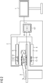
- This computer program and therefore the corresponding method can be carried out by a system which is schematically illustrated in FIG 2 as an MRI device 2.
- FIG 2 an MRI device 2.
- the MRI device 2 is presently adapted to image a patient 3 based on a magnetic resonance imaging technique.
- the patient 3 serves as the subject whose motion is to be monitored using the mentioned method.
- the motion of the patient 3 shall be monitored while magnetic resonance imaging data (MR data) of the patient 3 is acquired by means of the MRI device 2.
- the MRI device 2 presently comprises an imaging system 4, which is also only schematically represented here.
- the imaging system 4 comprises at least a body coil 5 surrounding the patient 3 and adapted to generate a magnetic field in a volume occupied by the patient 3.
- the imaging system 4 also comprises multiple local coils 6 which are presently arranged in close proximity to the patient 3, in particular on and under him.
- the imaging system 4 also comprises a signal processing unit 7, which is connected to some or all of the coils 5, 6.
- the signal processing unit 7 presently comprises a processor 8 and connected thereto a data store 9, and is adapted to process MR echo signals, i.e. MR data received or measured by means of the local coils 6.
- the signal processing unit 7 can also be adapted to control the body coil 5 or a sequence of RF-pulses transmitted therewith as part of the magnetic resonance imaging process.
- Respective MR images of the patient 3 generated or reconstructed from the MR data by the signal processing unit 7 can be displayed using a connected display device 11.
- signal processing unit 7 is represented as a single unit this is to be understood as purely exemplary and schematically. In a practical implementation the signal processing unit 7 may be divided into or comprise several individual units for the multiple functions or purposes of the signal processing unit 7 as described herein.
- the data store 9 may contain a computer program that can be executed by the processor 8 and that contains or comprises instructions representing the method for monitoring the motion of the patient 3, i.e. the flow chart 1, to cause the processor 8 or the signal processing unit 7 or the MRI device 2 to execute said method.
- At least one pseudo random spreading code is provided.
- multiple orthogonal spreading codes can be provided.
- the spreading codes can, for example, be stored in or loaded into the data store 9.
- a spread-spectrum technique is performed to generate a spectrally spread out monitoring signal based on the provided pseudo random spreading code. If multiple spreading codes are provided, multiple different corresponding modulations can be performed to generate multiple different monitoring signals or multiple differently modulated instances of the monitoring signal. This can be automatically performed by the signal processing unit 7.
- each monitoring signal is coupled out in process step S3 as a reference representing the original or unchanged monitoring signal as intended for transmission.
- Respective remaining parts of the monitoring signals are transmitted or emitted in process step S4 by means of dedicated transmission antennas 10.
- These transmission antennas 10 are presently integrated into or arranged in the body coil 5 but are actually individually controllable devices.
- Each of the transmission antennas 10 is used to emit a differently modulated one of the monitoring signals with orthogonal modulations towards the patient 3 and the local coils 6.
- the monitoring signals can be continuously or regularly emitted, which is indicated here by a looping program path P2.
- process step S5 the parts of the monitoring signal is transmitted by the transmission antennas 10 are received by means of the local coils 6.
- the patient 3 might be moving, for example due to a breathing motion, which influences the received monitoring signal is.
- Corresponding to the continuous or regular a mission of the monitoring signal is they can also be received continuously or regularly as indicated by a looping programme path P3.
- the monitoring signals received by the local coils 6 are provided to the signal processing unit 7 via a wired connection.
- process step S6 the signal processing unit 7 analyses the received monitoring signals to determine a change corresponding to or indicating the motion of the patient 3.
- the monitoring signals received by the local coils 6 can be compared to the part of the original monitoring signal that was coupled out in process step S3.
- This coupled out part can, in other words, be kept in the signal processing unit 7 or can be coupled out essentially and the transmission antennas 10 and directly provided to the signal processing unit 7 through a wired connection without being subjected to any potentially signal changing influence of the patient 3 or his motion.
- process step S7 it is determined if a detected change in the monitoring signal is consistent with possible motions of the patient 3.
- These possible motions and/or corresponding changes in the monitoring signals can be experimentally (pre-)determined and provided as input data for the signal processing unit 7. If it is determined, that the detected change is inconsistent with a motion of the patient 3 or inconsistent with being caused by the motion of the patient 3 the flow chart 1 follows program path P4 to process step S8.
- process step S8 the detected change might be discarded or stored as an indication of a possible error for later analysis.
- the method can then continue to detect any additional subsequent changes in the monitoring signals, since as mentioned they can be continuously or regularly received or recorded. If at one point or in one iteration of process step S7 it is determined that a detected change in the monitoring signal is consistent with a motion of the patient 3 or with being caused by the motion of the patient 3, the flow chart 1 follows program path P7 to process step S9.
- process step S9 the corresponding motion of the patient 3 is determined by the signal processing unit 7.
- the determined motion or corresponding motion data characterising or describing this motion can be provided by the signal processing unit 7 or one of its functions or modules as an output, for example to another function, module, subroutine, or device.
- the motion data can be provided to an image reconstruction module of the signal processing unit 7 that is adapted or configured to reconstruct a motion-compensated MR image of the patient 3 based on the received MR data and the determined motion of the patient 3.
- the signal processing unit 7 can - depending on an implementation of the described method - for example be adapted or configured to separate different frequency bands used for the monitoring signals and/or the RF-pulses or MR echo signals, and/or be adapted or configured to separate corresponding different signal portions when overlapping frequencies or frequency bands are used.
- the basic idea of co-transmitting the monitoring signal in the frequency band used for the magnetic resonance imaging and using subtraction coefficients (wk or time-dependent: wk(t)) determined for separating signals and thereby cleaning or correcting the MR data or corresponding MR image as useful information, in this case for determining the motion of the patient 3, can analogously be used in or applied to other applications.
- the broadband spreading out of the monitoring signal can enable additional ways of handling, using, or processing the monitoring signal for different types of applications and situations.
- the described examples show how a patient motion or movement can be monitored by means of a spread-spectrum modulated test signal and corresponding transmission and receiving antennas or arrays.
Landscapes
- Health & Medical Sciences (AREA)
- Life Sciences & Earth Sciences (AREA)
- Physics & Mathematics (AREA)
- Engineering & Computer Science (AREA)
- Biophysics (AREA)
- General Health & Medical Sciences (AREA)
- Medical Informatics (AREA)
- Animal Behavior & Ethology (AREA)
- Surgery (AREA)
- General Physics & Mathematics (AREA)
- Molecular Biology (AREA)
- Veterinary Medicine (AREA)
- Public Health (AREA)
- Pathology (AREA)
- Biomedical Technology (AREA)
- Heart & Thoracic Surgery (AREA)
- Nuclear Medicine, Radiotherapy & Molecular Imaging (AREA)
- Physiology (AREA)
- Signal Processing (AREA)
- Condensed Matter Physics & Semiconductors (AREA)
- Radiology & Medical Imaging (AREA)
- High Energy & Nuclear Physics (AREA)
- Computer Vision & Pattern Recognition (AREA)
- Psychiatry (AREA)
- Artificial Intelligence (AREA)
- Radar, Positioning & Navigation (AREA)
- Remote Sensing (AREA)
- Cardiology (AREA)
- Power Engineering (AREA)
- Pulmonology (AREA)
- Dentistry (AREA)
- Oral & Maxillofacial Surgery (AREA)
- Magnetic Resonance Imaging Apparatus (AREA)
Abstract
Description
- The present invention relates to a method for monitoring a motion of a subject, such as a patient. The present invention further relates to a corresponding system and a corresponding computer program product.
- With technological advances in medical techniques as well as in signal and data processing many applications can benefit from taking into account a motion of a respective subject, such as a patient. A known example for this is motion compensated imaging or image reconstruction, where for example a motion due to a heartbeat or a breathing motion of the patient can be taken into account to reduce image artefacts or blurring.
- For example in magnetic resonance imaging (MRI) it has been suggested to use a pilot tone method, wherein a test signal is transmitted outside of an MR frequency band, that is, a frequency band used for the magnetic resonance imaging. Such a test signal can have a spectral distance or frequency distance to the MR frequency band of about 0.1 MHz to 5 MHz or even up to, for example, 300 MHz with a frequency that can typically be a multiple of 2.5 MHz to keep intermodulation products or harmonic interference out of the MR frequency band.
- Approaches that have been tried or suggested so far do, however, have some disadvantages. For example, it can require a lot of additional filtering effort on a receiver side or signal processing side to separate the frequency bands of the test signal and an MR signal, and even then it can be difficult to keep point artefacts or stripe artefacts caused by the test signal out of resulting MR images. AT least in part this has to do with relatively high levels or signal strengths used for the test signal to achieve a sufficient signal-to-noise ratio. Here, another disadvantage or problem is that a transmission power for the test signal can be limited by a dynamic range of a receiver system of a respective MRI device. It is easily possible for the test signal to load the receiver system and in particular an analog compander in a range where additional noise or even nonlinearities in the receiver system or a receiver chain can be generated, which in turn can negatively affect image quality of resulting MR images. Furthermore, the test signal can lead to problems with electromagnetic compatibility (EMC) and/or electromagnetic emissions exceeding safety limits.
- It is an objective of the present invention to address these problems and to enable motion monitoring with improved robustness and reliability. This objective is achieved by the subject matter of the independent claims. Advantageous embodiments with expedient developments of the present invention are indicated in the dependent claims as well as in the description and in the drawings.
- The method according to the present invention can be used for monitoring a motion of a subject, such as a patient. These can for example be motions caused by a heartbeat or breathing of the patient and/or other voluntary or involuntary movements. The presently described method can particularly successfully be employed for monitoring or detecting cyclical or repeating motions but is not necessarily limited thereto. In a process step of the method according to the present invention a monitoring signal is emitted towards a corresponding receiver. In terms of the present invention the monitoring signal is an electromagnetic signal, such as a radio signal, that is transmitted wirelessly from a sender or transmitter, in particular a transmitting antenna, to the receiver.
- The receiver can preferably be placed on or at the subject or on a side of the subject opposite the transmitter. Correspondingly, on its way from the transmitter to the receiver the monitoring signal can encounter the subject or interact with the subject, which, depending on the motion of the subject at that time, can influence the monitoring signal, i.e. lead to a detectable change in the monitoring signal.
- Correspondingly, in another step of the method according to the present invention the motion of the subject is detected based on a change in the received monitoring signal. For this, the received monitoring signal that is received or measured by means of the receiver can be recorded so that a change over time of the received monitoring signal can be detected by analysing the recorded received monitoring signal. Additionally or alternatively the received monitoring signal can be compared to a provided reference signal or reference signal form. This reference signal can be or represent the unchanged, originally transmitted monitoring signal or, for example, a signal or signal form that is expected as the received monitoring signal for a predetermined state or motion of the subject.
- In a first alternative of the present invention the monitoring signal is emitted using a spread-spectrum technique. In an additional or alternative second variant of the present invention the monitoring signal is emitted using an M-to-N multi-antenna emitter-receiver system with a set or number of N transmitting antenna and a set or number of N receiving antennas. In particular, the number M of transmitting antennas can be smaller than the number N of receiving antennas. It is, however, also possible for the numbers M and N to be equal.
- The present invention is based on the insight or overarching idea that by adapting the transmission and reception of the monitoring signal an improved robustness and reliability for detecting and monitoring the motion can be achieved. To do so, both variants of the present invention can be employed individually or in combination with each other. Using the spread-spectrum technique, i.e. a spread-spectrum signal modulation, can be particularly advantageous to make the monitoring signal and therefore the monitoring or detection of the motion more robust or resistant against noise or interference, in particular from narrowband sources. It also advantageously enables use of lower peak levels of the monitoring signal compared to other approaches where an unmodulated test signal might be used. This makes it easier to comply with EMC safety limits and also means that more frequencies or frequency bands can be used for the monitoring signal, giving the presently described method improved flexibility and adaptability to respective local circumstances.
- Since as part of the spread-spectrum technique an energy of the monitoring signal can be spectrally spread out, crosstalk or interference with other electronic equipment can also be limited. If, for example the method according to the present invention is used in conjunction or connection with an imaging technique, such as magnetic resonance imaging (MRI), discrete image artefacts such as bright points, spots or stripes in resulting images of the subject can more easily be avoided due to the monitoring signal being spectrally spread out, leading to an overall improved image quality. Using the spread-spectrum technique for emitting the monitoring signal can also bring with it or enable additional advantages and benefits that will be described further down below in connection with advantageous developments of the present invention.
- It is to be noted that the present invention is not limited to any one specific spread-spectrum technique so that any technique that spreads out the monitoring signal over a frequency band, in particular a frequency band that is wider than the monitoring signal or its bandwidth before spreading it out or strictly needed for its transmission, can be used in the method according to the present invention.
- Using the M-to-N multi-antenna emitter-receiver system, i.e. an M-to-N transmission technique, can also make monitoring and detecting the motion of the subject more robust and reliable. For example, the multi-antenna emitter-receiver system can enable or provide multiple coupling paths for the monitoring signal through the subject and is therefore not reliant on a single such path. This can advantageously provide robustness or resistance against localised disturbances, interference or signal blocking. It can also provide a spatial resolution for the motion when the N receiving antennas are arranged in a spatially spread out layout or pattern.
- This can advantageously offer an additional aspect or additional data for verifying that a detected change in the monitoring signal does indeed represent or correspond to a motion of the subject. For example, a particular spatial pattern of the received monitoring signal or its change might be associated with the motion in question, whereas a different spatial pattern might be inconsistent with any physically possible motion and can therefore indicate a disturbance, interference, or measurement error. An example for the latter might be if a change in the monitoring signal - possibly above a predetermined threshold - is only detected in one of the receiving antennas, which would indicate a discontinuous motion of the subject that might not physically be possible, since neighbouring parts of the subject might be connected to each other and therefore always move in conjunction with each other and/or with smoothly changing amplitudes.
- Regardless of which variant of the present invention is used, it is a particular advantage that the present invention can be used to monitor the motion of the respective subject as part of an imaging technique or other observation or examination technique for the respective subject, or independent thereof, i.e. on its own. For example, using the present invention the motion of the subject can be monitored during a preparation phase, where the subject might be positioned by medical personnel for later imaging or examination, i.e. in a situation with essentially unpredictably moving personnel and devices as well as potential exposure of medical personnel to any emitted signals. In such situations the respective imaging technique can typically not be used reliably and safely.
- In an advantageous development of the present invention a phase and an amplitude of the emitted monitoring signal is determined as a reference for detecting the change in the monitoring signal. In a first variant this is done by making the emitted monitoring signal carry a predetermined digital signal and by performing a calibration of an analog emitter or transmitter that is used for emitting the monitoring signal. This calibration is performed prior to emitting or transmitting the monitoring signal. This means that the emitted monitoring signal is fully predetermined and therefore known in terms of its phase, amplitude and signal form or content and can thus reliably be used as a reference to detect any changes or deviations in the received monitoring signal.
- In an additional or alternative variant the reference is determined by coupling out a part of the monitoring signal to be emitted at the emitter or transmitter and providing this coupled out part directly to a signal processing unit adapted for detecting the change in the monitoring signal. In particular, the coupled out part of the monitoring signal can be provided or transmitted to the signal processing unit via a wired, and preferably electromagnetically shielded, connection to the signal processing unit.
- It could also be possible to place a reference receiver in close proximity to the emitter or transmitter used for emitting the monitoring signal. This means that at least the part of the emitted monitoring signal can be transmitted from the emitter to the reference receiver wirelessly but without passing through or being reflected from the subject and therefore without being influenced by the subject or its motion. The reference receiver can then be physically coupled to the signal processing unit for providing it with the monitoring signal received as a reference by means of the reference receiver through a wired connection or transmission path.
- In these additional or alternative variants the actually sent or emitted monitoring signal can advantageously directly be used as the reference as it is actually sent, even without any predetermination or prior knowledge of its properties before transmission. Here, determining the phase and amplitude of the emitted monitoring signal can mean that these properties are measured for the coupled out part of the monitoring signal by the signal processing unit.
- The reference or reference signal determined here can advantageously enable a particularly precise, robust, reliable, and fast detection of any changes in the monitoring signal and therefore of the motion of the subject.
- In a further advantageous development of the present invention in the variant where the monitoring signal is emitted using the spread-spectrum technique, the spread out monitoring signal is generated through a modulation with a predetermined pseudo random spreading code. In other words, the monitoring signal or a digital signal carried thereby is combined with the pseudo random spreading code to spread out the monitoring signal or its information content or energy. Using a pseudo random spreading code can advantageously make the spectrally spread-out emitted monitoring signal particularly similar to broadband noise. This in turn means that any effects or artefacts caused by the monitoring signal in any other equipment or parallel data or signal processing, such as imaging data of the subject obtained while monitoring the motion by means of the monitoring signal, can appear as random noise. This advantageously can for example improve an image quality and/or limit or avoid false positive detections of features due to artefacts caused by the monitoring signal.
- In a further advantageous development of the present invention the motion monitoring is combined with a magnetic resonance based method for imaging the subject, i.e. with MRI. Therein, a frequency or a frequency band of the monitoring signal is set to partly or fully overlap a frequency band of a magnetic resonance imaging signal used for imaging the subject. The monitoring signal for monitoring the motion of the subject and a useful signal for the MRI do, in other words, spectrally overlap. The monitoring signal and the useful signal for the MRI, i.e. the magnetic resonance imaging signal, can also temporarily overlap each other, meaning that they can be transmitted and/or received essentially simultaneously or during the same predetermined windows or period of time, for example during application of a predetermined MRI sequence or a respective MR acquisition window. The magnetic resonance imaging signal in this sense can be or comprise RF-pulses emitted as part of the MRI process and/or a corresponding magnetic resonance echo signal received as part of the MRI process.
- Using at least partially the same frequency or frequency band for the monitoring signal and the MRI signal or MR imaging process has the advantage of reducing or avoiding hardware complexity such as additional filters for separating different frequencies or frequency bands. Also, at least part of the hardware used for the magnetic resonance imaging, in particular one or more coils of a corresponding MRI device, can then also be used for transmitting or receiving the monitoring signal without any significant modifications, further reducing hardware complexity and cost. A further advantage is that this proposed development of the present invention enables calibration or testing of at least part of a signal chain used for the magnetic resonance imaging through or by means of the monitoring signal, which typically can be generated more easily and safely than the actual magnetic resonance imaging signal.
- Separation of the monitoring signal and the MRI signal can advantageously be done in software, which can reduce cost and complexity and provide increased flexibility and adaptability of the proposed method compared to a fully hardware-dependent solution. Particularly when using the spread-spectrum technique the spectral - and possibly temporal - overlap of the monitoring signal and the magnetic resonance imaging signal does in practice not lead to any coherent image interference or artefacts. This is the case, because the monitoring signal can be made so weak or low level that it can essentially disappear in a noise level of the MRI signal. This advantageously offers the possibility to forego active suppression of the monitoring signal in the received MRI signal before generating or reconstructing a respective magnetic resonance image therefrom.
- In a further advantageous development of the present invention a coil used for a magnetic resonance imaging is also used for emitting and/or receiving the monitoring signal. As described, this can advantageously reduce the amount of required hardware and therefore corresponding complexity and cost, and can allow for easy and effective calibration and/or testing of at least part of the MRI signal chain by using the monitoring signal. Preferably, the monitoring signal is received by means of at least one MRI local coil, especially preferred by means of an array of multiple spatially distributed MRI local coils. Local coils in this sense are coils that are intended or adapted for placement on or at the subject for the MRI process.
- However, for emitting the monitoring signal at least one separate transmitting antenna that is different from an MRI transmitting coil is used. The separate transmitting coil used for emitting more transmitting the monitoring signal is, in other words, not used in the magnetic resonance imaging of the subject. The at least one separate transmitting antenna can preferably be integrated in or with the MRI transmitting coil or at least a housing of a respective MRI device or system.
- This approach, i.e. using dedicated antennas or hardware for emitting the monitoring signal and not using antennas, coils or hardware used or adapted for the magnetic resonance imaging, can advantageously provide more flexibility, precision, and reliability both for monitoring the motion and for imaging the subject. This can be the case at least in part because RF-pulses emitted using the MRI transmitting coil for the magnetic resonance imaging and the monitoring signal can differ from each other significantly in terms of power, timescale or signal length, dynamic range, signal form, et cetera. Therefore, using different hardware for transmitting the monitoring signal and transmitting the RF-pulses for the magnetic resonance imaging can offer significant optimisation potential.
- For example, a transmitting power for the RF-pulses for the magnetic resonance imaging can be on the order of several kilowatts, while the transmitting power for the monitoring signal can be on the order of several microwatts or even nan-owatts. Similarly, a timescale or length of the RF pulses can be on the order of at most a few milliseconds while the monitoring signal can be emitted over periods of, for example, more than 100 ms at a time.
- Using dedicated transmitting antennas for emitting the monitoring signal can also represent a relatively easy and cheap to implement way for realising the multi-antenna emitter-receiver system for the M-to-N transmission technique for the monitoring signal, since the transmitting antennas for the monitoring signal can typically be significantly smaller and cheaper than the MRI transmitting coil or coils and might, for example, not require a similarly sophisticated cooling system as the MRI transmitting coil or coils.
- In a further advantageous development of the present invention the monitoring signal, in particular its energy, is essentially uniformly spread out over a predetermined frequency band using the spread-spectrum technique. A signal level or signal strength of the monitoring signal is set so that at each frequency it is essentially at or below a noise level of a received, i.e. measured or detected, magnetic resonance echo signal, i.e. of the MR echo signal or signals from which an MR image of the subject is to be generated or reconstructed as part of the magnetic resonance based imaging of the subject. The received monitoring signal is then separated from the received MR echo signal through signal averaging over at least one time period that is long relative to or compared to a measurement period, such as an or acquisition window, defined in a respective MR imaging sequence or protocol, preferably over at least 100 ms.
- The measurement period in this sense is a period or window of time during which the MR echo signal, for example an echo train, is received or recorded. With the level of the monitoring signal set relatively low in this manner even imperfect separation or suppression of the monitoring signal in the MR echo signal does advantageously not lead to a significantly reduced image quality or spatially discrete image artefacts, because the energy of the monitoring signal is uniformly spread out. This limits any influences of the monitoring signal on the reconstructed MR image to similarly spread out noise. As mentioned, this means that a complexity or sophistication of a signal processing for reconstructing the MR image can advantageously be reduced effectively without any significant negative effects. Even so, the motion of the subject can still be monitored, since measurement or detection of the monitoring signal is not limited by the timescale or sequence of the magnetic resonance imaging process or signal, which allows for separating out or extracting the monitoring signal over the mentioned relatively long period or periods of time.
- The monitoring signal might on shorter timescales appear as noise but since it is actually not true noise but rather a predetermined signal, it can be separated from any true noise by averaging which only averages out the random noise but not the actually not-random monitoring signal which therefore becomes more pronounced. While timescales of, for example, 100 ms are long relative to or compared to signalling timescales of individual RF-pulses and echoes of the magnetic resonance imaging process or sequence, they are still relatively short compared to a speed or timescale of typical macroscopic motions or movements of a subject or patient. Therefore, even with the described averaging the motion of the subject can still be reliably and, at least for practical purposes, continuously tracked or monitored.
- In a further advantageous development of the present invention the received monitoring signal and the MR echo signal are measured together, for example as a combined signal. For separating out the received monitoring signal from the measured combined signal a (complex) weighting factor for minimising a correlation between the two signal parts, i.e. the monitoring signal and the MR echo signal, is determined and applied to the combined measured signal. By determining and applying the weighting factor in this manner it becomes possible to subtract the monitoring signal and thus allow for monitoring the motion as well as for reconstructing an essentially artefact-free MR image even though the monitoring signal and the MR echo signal can spectrally overlap each other. This signal processing to separate the monitoring signal from the MR echo signal can advantageously be performed in software, i.e. without necessarily relying on dedicated or specialised hardware, and can thus provide improved flexibility and adaptability and a relatively cheap and easy avenue for optimisation.
- Optimally, a weighting factor would be determined that leads to a correlation of zero between the two signal parts. But even if that cannot be readily achieved, resulting in an imperfect separation of the two signal parts, potential negative effects can be mitigated through the spread-spectrum technique as described.
- In a further advantageous development of the present invention a signal reception chain through which the MR echo signal is received and processed is continuously or regularly calibrated or recalibrated during the magnetic resonance imaging and the parallel motion monitoring based on detected variations in the received monitoring signal that are not associated with, i.e. do not correspond to the motion of the subject. Such variations can, for example, comprise a drift of the received monitoring signal in one direction over time. They can also be variations on a different timescale than a typical motion or movement of the subject, and/or the like. Preferably, these variations or fluctuations, in particular in a signal gain, can be continuously recorded. They can then be used as a basis for calibrating or recalibrating the signal reception chain. They can also be used as a basis for quality testing of the signal reception chain or as a reference for improving signal stability, for example in applications with particularly high demands for signal stability.
- Such variations in the received monitoring signal that are not associated with the motion of the subject can, for example, be caused by changes in temperature of the signal reception chain during operation, by increasing or decreasing surrounding humidity, by interference or disturbances in an electric supply or grid, by external sources of interference, and/or the like. Here, the monitoring signal can, in other words, not only be used for monitoring a motion of the subject, but also for improving an accuracy and reliability of any measured signals and/or corresponding signal processing or any results based thereon. This can advantageously be achieved without additional hardware.
- In a further advantageous development of the present invention a length of a predetermined pseudo random spreading code used to spread out the monitoring signal as part of the spread-spectrum technique is set so that the monitoring signal is spread out essentially across the full bandwidth of an MRI receiving coil or coils or essentially a full width of a frequency band used for the magnetic resonance imaging. By using such a long spreading code the method for monitoring the motion of the subject can be made particularly robust against external interference or disturbances. Also, by essentially maximally spreading out the monitoring signal within the limits or boundaries of the hardware used for the magnetic resonance imaging the level or signal strength of the monitoring signal can be minimised without compromising its function, thereby reducing or minimising any effects of the monitoring signal on the image quality of the respective MR images. In particular, these advantages can be achieved without requiring any additional or modified hardware, which advantageously reduces corresponding complexity and cost.
- In a further advantageous development of the present invention the motion monitoring using the M-to-N multi-antenna emitter-receiver system is combined with a magnetic resonance based method for imaging the subject. Therein, a frequency or frequency band of the monitoring signal is set to be outside of the frequency or frequency band used for the magnetic resonance imaging. Using different frequencies or frequency bands for the motion monitoring on the one hand side and for the MR-based imaging of the subject on the other hand side can advantageously limit interference or interplay between respective signals and can provide a straightforward way of separating the respective signals for both purposes. It can potentially also enable reception or measurement of the monitoring signal even during transmission of the RF-pulses for the magnetic resonance imaging. This will typically not be possible when the same frequencies are used, because the RF-pulses would overpower and drown out the monitoring signal due to their typically several orders of magnitude higher power output. Therefore, using different frequencies or frequency bands advantageously enable continuous monitoring of the motion of the subject.
- Additionally, using different frequencies enables improved flexibility and adaptability of the presently proposed method to local circumstances, since the frequency or frequency band used for the motion monitoring does not have to be tied to the typically fixed and unchangeable frequency or frequency band for the magnetic resonance imaging. This can enable the use of the proposed method for motion monitoring even when, for example, in a particular situation a narrowband source of interference or noise is present, since then a different frequency or frequency band can be used for the monitoring signal.
- The frequency or frequency band for the monitoring signal can, in other words, be manually or automatically be selected in dependence of an ambient spectrum of interference or noise that is respectively present, for example at the location of the subject in any given situation or at any given application of the presently proposed method. For this purpose, the ambient electromagnetic spectrum or noise can, preferably automatically, be measured and analysed to determine a suitable frequency or frequency band for the monitoring signal. For example, a frequency or frequency band with a local minimum of noise, activity or transmitted energy that is closest to the frequency band used for the magnetic resonance imaging can automatically be used or selected for the monitoring signal. This can be advantageous, because if a spectral distance or frequency distance between the frequency or frequency bands for the monitoring signal and the magnetic resonance imaging is lower or smaller than a predetermined threshold, it can be possible to use at least part of a signal chain for the magnetic resonance imaging also for the transmission or reception and/or processing of the monitoring signal.
- In a further advantageous development of the present invention the monitoring signal is emitted and /or received at least between pulses, i.e. the mentioned RF-pulses, of the respective magnetic resonance imaging sequence that is applied for imaging the subject. The monitoring signal is, in other words, emitted and/or received for example after one or more, preferably after each, RF-pulse of the MRI sequence during an echo time or during measurement of the MR echo signal. Alternatively or additionally the monitoring signal can be emitted and/or received after measurement of a respective MR echo signal and before the respective next RF-pulse of the MRI sequence i.e. during the MRI sequence but not actually at the time of transmission of the MR pulses. This means that the monitoring signal can be emitted and/or received during at least part of a respective MR acquisition window.
- This means that the motion of the subject can actually be monitored during the acquisition of MR data from which he respective MR image of the subject can be reconstructed. Therefore, a particularly precise temporal correlation between measured MR data, i.e. the received MR echo signal, and the determined motion of the subject can be achieved. In particular, no extrapolation or interpolation might be necessary for determining the actual motion of the subject during the MR acquisition window.
- It is, however, also possible to emit and/or receive the monitoring signal outside of the respective MR acquisition window. This might be useful for the mentioned averaging and/or for continuously monitoring the motion of the subject, for example between or across multiple MR data acquisitions, observations, and/or examinations of the subject to enable continuity of corresponding motion data and therefore of knowledge of a respective position of the subject.
- In a further advantageous development of the present invention the monitoring signal is emitted using the spread-spectrum technique and using multiple emitters of the M-to-N multi-antenna emitter-receiver system at the same time. Therein, different modulations that are orthogonal with respect to each other are used for emitting the monitoring signal through the multiple emitters. In other words, multiple parts or instances of the monitoring signal are emitted from different ones of the multiple emitters at the same time with each part or instance using a different modulation.
- These different modulations can preferably be based on or generated using orthogonal spreading codes. Separation of the multiple parts or instances of the monitoring signal, which can also be interpreted as multiple parallel monitoring signals, is then possible due to the orthogonality of their modulations or the respective spreading codes. This means, that effectively a code multiplexing method can be applied to the motion monitoring. In particular, separation of the multiple parallel monitoring signals is even possible when the same frequency or a frequency band is used for some or all of the multiple parallel monitoring signals, i.e. when they spectrally overlap.
- It is, however, also possible to use separate or only partly overlapping frequencies are frequency bands for some or all of the multiple parallel monitoring signals. A separation of these frequencies are frequency bands can then be achieved or supported for example by means of respective frequency filters.
- Using multiple emitters and thus multiple coupling paths of or for the monitoring signal through the subject and emitting the multiple parallel monitoring signals at the same time can advantageously provide additional information and thus a more robust, reliable, and complete determination or characterisation of the motion of the subject.
- Since the emitters or transmission antennas can be relatively small, achieving this does advantageously not require an unreasonable amount of effort or cost.
- Another aspect of the present invention is a system for monitoring a motion of a subject. The system comprises emitting means for emitting or transmitting a predetermined monitoring signal, receiving means for receiving the emitted or transmitted monitoring signal, and a signal processing unit for detecting the motion of the subject based on a change in the received monitoring signal. The system according to the present invention is adapted to, automatically or semi-automatically, execute or perform the method according to the present invention. Since as described in connection with the method according to the present invention a combination with an imaging process for imaging the subject, in particular with a magnetic resonance based imaging process, is possible, the system according to the present invention can also comprise corresponding imaging means, such as an MRI device or MRI subsystem.
- Since the system according to the present invention is adapted to carry out the method according to the present invention, the system can have or comprise any or all of the advantages, developments, and/or means or devices mentioned in connection with the method according to the present invention, and/or can be adapted to carry out any additional steps, procedures, or processes mentioned in connection with the method according to the present invention.
- The emitting means can comprise at least one transmission antenna, in particular the set of M transmitting antennas of the multi-antenna emitter-receiver system. The emitting means may also comprise a signal generator for generating the monitoring signal, and/or other signal processing or signal forming means.
- The receiving means may comprise at least one receiver or receiving antenna, in particular the set of N receiving antennas of the multi-antenna emitter-receiver system. The receiving means may also comprise additional means or parts, such as a filter, etc. Preferably, the receiving means can be coupled or connected to the signal processing unit through a wired connection over which the monitoring signal received by the receiving means can be (directly) provided to the signal processing unit.
- The signal processing unit can comprise one or more electric and/or electronic circuits, a processor, in particular a microchip or microprocessor, a data store connected thereto with an operating system or program code stored thereon, and/or the like. This data store and/or program code can represent or encode the process steps of the method according to the present invention and they can themselves be another aspect of the present invention in the form of a computer program product. The computer program product according to the present invention does, in other words, comprise instructions to cause the system according to the present invention to, automatically or semi-automatically, execute the method according to the present invention. The computer program product according to the present invention can be a computer program or program code executable by a processing means, in particular the system according to the present invention or its signal processing unit. The method according to the present invention can, in other words, be partly or fully computer implemented. The computer program product according to the present invention may also be a computer-readable storage medium, whereon such a computer program or program code is stored.
- The embodiments and developments of the present invention described herein for at least one aspect of the present invention, that is, at least for the method, the system, and the computer program product, as well as the corresponding advantages may be applied to any and all aspects of the present invention.
- Further advantages, features, and details of the present invention derive from the following description of preferred embodiments of the present invention as well as from the drawings pertaining to the present invention. The features and feature combinations previously mentioned in the description as well as the features and feature combinations mentioned in the following description of the figures and/or shown in the figures alone can be employed not only in the respectively indicated combination but also in other combinations or taken alone without leaving the scope of the present invention. In the drawings
- FIG 1
- schematically illustrates an example of a flow chart for a method for monitoring a motion of a subject; and
- FIG 2
- schematically illustrates a system for carrying out the method.
- The examples described below refer to preferred embodiments of the present invention. Therein, individual components and process steps of the embodiments each constitute individual, independent features of the present invention that can further develop the invention independently of each other as well as in combinations not explicitly described. The described embodiments can be further developed or supplemented by features, components and/or steps already described above.
-
FIG 1 schematically shows an example for aflow chart 1 for a method for monitoring a motion of a subject. This method is illustrated here by process steps S1 to S10 and program paths P1 to P6, both of which can represent corresponding instructions, routines, or program modules of a corresponding computer program or computer program product. This computer program and therefore the corresponding method can be carried out by a system which is schematically illustrated inFIG 2 as an MRI device 2. Below, the method, i.e. theflow chart 1 will be explained with reference toFIG 1 andFIG 2 . - The MRI device 2 is presently adapted to image a patient 3 based on a magnetic resonance imaging technique. Here, the patient 3 serves as the subject whose motion is to be monitored using the mentioned method. In particular, the motion of the patient 3 shall be monitored while magnetic resonance imaging data (MR data) of the patient 3 is acquired by means of the MRI device 2. The MRI device 2 presently comprises an imaging system 4, which is also only schematically represented here. The imaging system 4 comprises at least a
body coil 5 surrounding the patient 3 and adapted to generate a magnetic field in a volume occupied by the patient 3. The imaging system 4 also comprises multiple local coils 6 which are presently arranged in close proximity to the patient 3, in particular on and under him. Furthermore, the imaging system 4 also comprises a signal processing unit 7, which is connected to some or all of thecoils 5, 6. - The signal processing unit 7 presently comprises a
processor 8 and connected thereto adata store 9, and is adapted to process MR echo signals, i.e. MR data received or measured by means of the local coils 6. The signal processing unit 7 can also be adapted to control thebody coil 5 or a sequence of RF-pulses transmitted therewith as part of the magnetic resonance imaging process. Respective MR images of the patient 3 generated or reconstructed from the MR data by the signal processing unit 7 can be displayed using aconnected display device 11. - While the signal processing unit 7 is represented as a single unit this is to be understood as purely exemplary and schematically. In a practical implementation the signal processing unit 7 may be divided into or comprise several individual units for the multiple functions or purposes of the signal processing unit 7 as described herein.
- The
data store 9 may contain a computer program that can be executed by theprocessor 8 and that contains or comprises instructions representing the method for monitoring the motion of the patient 3, i.e. theflow chart 1, to cause theprocessor 8 or the signal processing unit 7 or the MRI device 2 to execute said method. - In process step S1 at least one pseudo random spreading code is provided. Preferably, multiple orthogonal spreading codes can be provided. The spreading codes can, for example, be stored in or loaded into the
data store 9. - In process step S2 a spread-spectrum technique is performed to generate a spectrally spread out monitoring signal based on the provided pseudo random spreading code. If multiple spreading codes are provided, multiple different corresponding modulations can be performed to generate multiple different monitoring signals or multiple differently modulated instances of the monitoring signal. This can be automatically performed by the signal processing unit 7.
- As indicated by a program path P1 a part of each monitoring signal is coupled out in process step S3 as a reference representing the original or unchanged monitoring signal as intended for transmission. Respective remaining parts of the monitoring signals are transmitted or emitted in process step S4 by means of
dedicated transmission antennas 10. Thesetransmission antennas 10 are presently integrated into or arranged in thebody coil 5 but are actually individually controllable devices. Each of thetransmission antennas 10 is used to emit a differently modulated one of the monitoring signals with orthogonal modulations towards the patient 3 and the local coils 6. The monitoring signals can be continuously or regularly emitted, which is indicated here by a looping program path P2. - In process step S5 the parts of the monitoring signal is transmitted by the
transmission antennas 10 are received by means of the local coils 6. At the same time the patient 3 might be moving, for example due to a breathing motion, which influences the received monitoring signal is. Corresponding to the continuous or regular a mission of the monitoring signal is they can also be received continuously or regularly as indicated by a looping programme path P3. - The monitoring signals received by the local coils 6 are provided to the signal processing unit 7 via a wired connection.
- In process step S6 the signal processing unit 7 analyses the received monitoring signals to determine a change corresponding to or indicating the motion of the patient 3.
- For this purpose the monitoring signals received by the local coils 6 can be compared to the part of the original monitoring signal that was coupled out in process step S3. This coupled out part can, in other words, be kept in the signal processing unit 7 or can be coupled out essentially and the
transmission antennas 10 and directly provided to the signal processing unit 7 through a wired connection without being subjected to any potentially signal changing influence of the patient 3 or his motion. - In process step S7 it is determined if a detected change in the monitoring signal is consistent with possible motions of the patient 3. These possible motions and/or corresponding changes in the monitoring signals, for example in terms of an amount of change, a speed of change, and/or a spatial distribution or a pattern of change, can be experimentally (pre-)determined and provided as input data for the signal processing unit 7. If it is determined, that the detected change is inconsistent with a motion of the patient 3 or inconsistent with being caused by the motion of the patient 3 the
flow chart 1 follows program path P4 to process step S8. - In process step S8 the detected change might be discarded or stored as an indication of a possible error for later analysis. As indicated by program path P5 the method can then continue to detect any additional subsequent changes in the monitoring signals, since as mentioned they can be continuously or regularly received or recorded. If at one point or in one iteration of process step S7 it is determined that a detected change in the monitoring signal is consistent with a motion of the patient 3 or with being caused by the motion of the patient 3, the
flow chart 1 follows program path P7 to process step S9. - In process step S9 the corresponding motion of the patient 3 is determined by the signal processing unit 7.
- In process step S10 the determined motion or corresponding motion data characterising or describing this motion can be provided by the signal processing unit 7 or one of its functions or modules as an output, for example to another function, module, subroutine, or device. For example, the motion data can be provided to an image reconstruction module of the signal processing unit 7 that is adapted or configured to reconstruct a motion-compensated MR image of the patient 3 based on the received MR data and the determined motion of the patient 3.
- While the method for monitoring or detecting the motion of the patient 3 has he been described in connection with magnetic resonance imaging of the patient 3, it can also be performed independently thereof. It is also to be understood that the signal processing unit 7 can - depending on an implementation of the described method - for example be adapted or configured to separate different frequency bands used for the monitoring signals and/or the RF-pulses or MR echo signals, and/or be adapted or configured to separate corresponding different signal portions when overlapping frequencies or frequency bands are used. In particular, the basic idea of co-transmitting the monitoring signal in the frequency band used for the magnetic resonance imaging and using subtraction coefficients (wk or time-dependent: wk(t)) determined for separating signals and thereby cleaning or correcting the MR data or corresponding MR image as useful information, in this case for determining the motion of the patient 3, can analogously be used in or applied to other applications. Also, the broadband spreading out of the monitoring signal can enable additional ways of handling, using, or processing the monitoring signal for different types of applications and situations.
- In summary, the described examples show how a patient motion or movement can be monitored by means of a spread-spectrum modulated test signal and corresponding transmission and receiving antennas or arrays.
Claims (15)
- Method (1) for monitoring a motion of a subject (3), wherein- a monitoring signal is emitted towards a corresponding receiver (6),- the motion is detected based on a change in the received monitoring signal,wherein the monitoring signal is emitteda) using a spread-spectrum technique, and/orb) using an M-to-N multi-antenna emitter-receiver system (6, 7, 10) with a set of M transmitting antennas (10) and a set of N receiving antennas (6).
- Method (1) according to claim 1, characterised in that as a reference for detecting the change in the monitoring signal a phase and an amplitude of the emitted monitoring signal is determined- by the emitted monitoring signal carrying a predetermined digital signal and a calibration prior to emitting the monitoring signal of an analog emitter (10) used for emitting the monitoring signal, and/or- by coupling out a part of the monitoring signal to be emitted at the emitter (10) and providing this part directly to a signal processing unit (7) adapted for detecting the change in the monitoring signal.
- Method (1) according to any of the preceding claims, characterised in that when the monitoring signal is emitted using the spread-spectrum technique the monitoring signal is generated through modulation with a predetermined pseudo random spreading code.
- Method (1) according to any of the preceding claims, characterised in that the motion monitoring is combined with a magnetic resonance, MR, based method for imaging the subject (3), wherein a frequency of the monitoring signal is set to overlap a frequency band of a magnetic resonance imaging signal.
- Method (1) according to claim 4, characterised in that a coil (5, 6) used for the magnetic resonance imaging is also used for emitting and/or receiving the monitoring signal.
- Method (1) according to claim 5, characterised in that the monitoring signal is- received by means of at least one MR local coil (6), preferably an array of multiple spatially distributed MR local coils (6), but- emitted by means of at least one separate transmitting antenna (10) that is different from an MR transmitting coil (5) .
- Method (1) according to any of the claims 4 to 6, characterised in that- the monitoring signal is essentially uniformly spread out over a predetermined frequency band using the spread-spectrum technique,- a signal level of the monitoring signal is set so that at each frequency it is essentially at or below a noise level of a received MR echo signal, and- the received monitoring signal is separated from the received MR echo signal through signal averaging over at least one time period that is long compared to a measurement period defined in a respective MR imaging sequence, preferably at least 100 ms.
- Method (1) according to any of the claims 4 to 7, characterised in that the received monitoring signal and an MR echo signal are measured together and for separating out the received monitoring signal a weighting factor for minimising a correlation between the two signal parts is determined and applied to the measured signal.
- Method (1) according to any of the claims 4 to 8, characterised in that a signal reception chain through which an MR echo signal is received and processed is continuously or regularly calibrated during the MR imaging and the parallel motion monitoring based on detected variations in the received monitoring signal that are not associated with the motion of the subject (3) .
- Method (1) according to any of the claims 4 to 9, characterised in that a length of a predetermined pseudo random spreading code used to spread out the monitoring signal as part of the spread-spectrum technique is set so that the monitoring signal is spread out essentially across the full bandwidth of a magnetic resonance imaging receiving coil or coils or essentially a full width of a frequency band used for the magnetic resonance imaging.
- Method (1) according to any of the claims 1 to 3, characterised in that the motion monitoring using the M-to-N multi-antenna emitter-receiver system (6, 7, 10) is combined with a magnetic resonance based method for imaging the subject (3), wherein a frequency of the monitoring signal is set to be outside of a frequency band used for the magnetic resonance imaging.
- Method (1) according to any of the claims 4 to 11 characterised in that the monitoring signal is emitted and received at least between pulses of a MR imaging sequence that is applied for imaging the subject (3).
- Method (1) according to any of the preceding claims, characterised in that the monitoring signal is emitted using the spread-spectrum technique and using multiple emitters (10) of the M-to-N multi-antenna emitter-receiver system (6, 7, 10) at the same time, wherein different modulations that are orthogonal with respect to each other, in particular based on orthogonal spreading codes, are used for emitting the monitoring signal through the multiple emitters (10).
- System (2) for monitoring a motion of a subject (3), wherein the system (2) comprises emitting means (10) for emitting a predetermined monitoring signal, receiving means (6) for receiving the monitoring signal, and a signal processing unit (7) for detecting the motion of the subject (3) based on a change in the received monitoring signal, wherein the system (2) is adapted to execute the method (1) according to any of the preceding claims.
- Computer program product (1, 9) comprising instructions to cause the system (2) of the preceding claim to execute the method (1) according to any of the claims 1 to 13.
Priority Applications (2)
| Application Number | Priority Date | Filing Date | Title |
|---|---|---|---|
| EP19205630.7A EP3816647B1 (en) | 2019-10-28 | 2019-10-28 | Method and system for monitoring a motion of a subject, and corresponding computer program product |
| US17/074,774 US11672489B2 (en) | 2019-10-28 | 2020-10-20 | Method and system for monitoring a motion of a subject, and corresponding computer program product |
Applications Claiming Priority (1)
| Application Number | Priority Date | Filing Date | Title |
|---|---|---|---|
| EP19205630.7A EP3816647B1 (en) | 2019-10-28 | 2019-10-28 | Method and system for monitoring a motion of a subject, and corresponding computer program product |
Publications (2)
| Publication Number | Publication Date |
|---|---|
| EP3816647A1 true EP3816647A1 (en) | 2021-05-05 |
| EP3816647B1 EP3816647B1 (en) | 2024-06-26 |
Family
ID=68382301
Family Applications (1)
| Application Number | Title | Priority Date | Filing Date |
|---|---|---|---|
| EP19205630.7A Active EP3816647B1 (en) | 2019-10-28 | 2019-10-28 | Method and system for monitoring a motion of a subject, and corresponding computer program product |
Country Status (2)
| Country | Link |
|---|---|
| US (1) | US11672489B2 (en) |
| EP (1) | EP3816647B1 (en) |
Cited By (2)
| Publication number | Priority date | Publication date | Assignee | Title |
|---|---|---|---|---|
| CN114487954A (en) * | 2022-04-14 | 2022-05-13 | 中国科学院精密测量科学与技术创新研究院 | Multichannel receiving and transmitting NMR method for accurately measuring field intensity and distribution of electromagnet |
| EP4544997A1 (en) * | 2023-10-26 | 2025-04-30 | Siemens Healthineers AG | Method for acquiring a motion detection signal |
Families Citing this family (2)
| Publication number | Priority date | Publication date | Assignee | Title |
|---|---|---|---|---|
| EP3819653B1 (en) * | 2019-11-07 | 2023-09-06 | Siemens Healthcare GmbH | Method for testing a receive chain of a magnetic resonance tomograph |
| DE102022201313A1 (en) | 2022-02-09 | 2023-08-10 | Siemens Healthcare Gmbh | Method for determining movement information |
Citations (4)
| Publication number | Priority date | Publication date | Assignee | Title |
|---|---|---|---|---|
| US20100106008A1 (en) * | 2007-03-20 | 2010-04-29 | Koninklijke Philips Electronics N.V. | Magnetic resonance imaging system and method |
| US20150002331A1 (en) * | 2013-07-01 | 2015-01-01 | Siemens Aktiengesellschaft | Radar system for medical use |
| US20160245888A1 (en) * | 2015-02-25 | 2016-08-25 | Jan Bollenbeck | Generating motion information for an at least partially moving examination region |
| EP3486672A1 (en) * | 2017-11-16 | 2019-05-22 | Koninklijke Philips N.V. | Magnetic resonance imaging system with rf motion detection |
Family Cites Families (4)
| Publication number | Priority date | Publication date | Assignee | Title |
|---|---|---|---|---|
| DE102012216292B4 (en) | 2012-09-13 | 2021-02-18 | Siemens Healthcare Gmbh | Magnetic resonance assembly, a magnetic resonance device with the magnetic resonance assembly and a method for determining a movement of a patient during a magnetic resonance examination |
| US9753131B2 (en) * | 2013-10-09 | 2017-09-05 | Massachusetts Institute Of Technology | Motion tracking via body radio reflections |
| EP3304114A1 (en) * | 2015-05-27 | 2018-04-11 | Koninklijke Philips N.V. | Motion detection with multi element radio frequency antennas |
| EP3796020B1 (en) | 2019-09-17 | 2024-07-17 | Siemens Healthineers AG | Reception of useful signals in the magnetic resonance frequency band |
-
2019
- 2019-10-28 EP EP19205630.7A patent/EP3816647B1/en active Active
-
2020
- 2020-10-20 US US17/074,774 patent/US11672489B2/en active Active
Patent Citations (4)
| Publication number | Priority date | Publication date | Assignee | Title |
|---|---|---|---|---|
| US20100106008A1 (en) * | 2007-03-20 | 2010-04-29 | Koninklijke Philips Electronics N.V. | Magnetic resonance imaging system and method |
| US20150002331A1 (en) * | 2013-07-01 | 2015-01-01 | Siemens Aktiengesellschaft | Radar system for medical use |
| US20160245888A1 (en) * | 2015-02-25 | 2016-08-25 | Jan Bollenbeck | Generating motion information for an at least partially moving examination region |
| EP3486672A1 (en) * | 2017-11-16 | 2019-05-22 | Koninklijke Philips N.V. | Magnetic resonance imaging system with rf motion detection |
Cited By (3)
| Publication number | Priority date | Publication date | Assignee | Title |
|---|---|---|---|---|
| CN114487954A (en) * | 2022-04-14 | 2022-05-13 | 中国科学院精密测量科学与技术创新研究院 | Multichannel receiving and transmitting NMR method for accurately measuring field intensity and distribution of electromagnet |
| CN114487954B (en) * | 2022-04-14 | 2022-07-01 | 中国科学院精密测量科学与技术创新研究院 | Multichannel transmitting-receiving NMR method for accurately measuring field intensity and distribution of electromagnet |
| EP4544997A1 (en) * | 2023-10-26 | 2025-04-30 | Siemens Healthineers AG | Method for acquiring a motion detection signal |
Also Published As
| Publication number | Publication date |
|---|---|
| US11672489B2 (en) | 2023-06-13 |
| EP3816647B1 (en) | 2024-06-26 |
| US20210121131A1 (en) | 2021-04-29 |
Similar Documents
| Publication | Publication Date | Title |
|---|---|---|
| US11672489B2 (en) | Method and system for monitoring a motion of a subject, and corresponding computer program product | |
| CN111386470B (en) | Magnetic resonance tomography apparatus and method for operating a magnetic resonance tomography apparatus | |
| CN111214230B (en) | pilot tone mark | |
| CN112083367B (en) | Pilot tone equipment, magnetic resonance tomography equipment and operating method | |
| KR101939445B1 (en) | Method for ascertaining an item of movement information describing a movement in an at least partially moved examination region, and magnetic resonance device | |
| DE102015203385B4 (en) | Method for generating motion information to an at least partially moving examination area and magnetic resonance system and hybrid imaging modality | |
| US10722151B2 (en) | Magnetic resonance device having a motion detection unit and a method for detecting a movement of a patient during a magnetic resonance examination | |
| US11129576B2 (en) | Accurate heart rate measurement by radar using adaptive harmonics filter | |
| US9625541B2 (en) | Safety tests for systems monitoring local SAR | |
| US20100106008A1 (en) | Magnetic resonance imaging system and method | |
| US11035923B2 (en) | Magnetic resonance imaging apparatus | |
| US10928477B2 (en) | Magnetic resonance method and apparatus for obtaining patient movement information | |
| CN104825155A (en) | Analog cancellation of mri sequencing noise appearing in an ecg signal | |
| EP2358275A2 (en) | Optimial drive frequency selection in electrical tomography | |
| US20160003927A1 (en) | Power measurement on magnetic resonance imaging coil at different frequency than larmor frequency | |
| US12178564B2 (en) | Electromagnetic tracking and position measurement system having interference reduction from nearby instrumentation by filtering time-division multiplexed signal via step function | |
| US20230380689A1 (en) | Non-contact MRI in-bore motion sensing method using CW Doppler radar with band-pass filtering | |
| JP7051426B2 (en) | Magnetic resonance imaging device | |
| US10962620B2 (en) | Method and apparatus acquisition of MR measurement data in a breath-hold examination | |
| Lee et al. | MRI retrospective respiratory gating and cardiac sensing by CW Doppler radar: A feasibility study | |
| US20220065968A1 (en) | Respiratory detection transceiver | |
| EP3570059B1 (en) | Method and mri device for performing a quality analysis of an rf coil | |
| US20110046474A1 (en) | Method to correct interference signals in cardiac noise-triggering of medical data acquisition, and medical system operating according to the method | |
| JP2020096827A (en) | Detection device and method for detecting respiratory movements, computer program, computer readable storage medium and medical device | |
| JPH037141A (en) | Magnetic resonant imaging method |
Legal Events
| Date | Code | Title | Description |
|---|---|---|---|
| PUAI | Public reference made under article 153(3) epc to a published international application that has entered the european phase |
Free format text: ORIGINAL CODE: 0009012 |
|
| STAA | Information on the status of an ep patent application or granted ep patent |
Free format text: STATUS: THE APPLICATION HAS BEEN PUBLISHED |
|
| AK | Designated contracting states |
Kind code of ref document: A1 Designated state(s): AL AT BE BG CH CY CZ DE DK EE ES FI FR GB GR HR HU IE IS IT LI LT LU LV MC MK MT NL NO PL PT RO RS SE SI SK SM TR |
|
| STAA | Information on the status of an ep patent application or granted ep patent |
Free format text: STATUS: REQUEST FOR EXAMINATION WAS MADE |
|
| 17P | Request for examination filed |
Effective date: 20211019 |
|
| RBV | Designated contracting states (corrected) |
Designated state(s): AL AT BE BG CH CY CZ DE DK EE ES FI FR GB GR HR HU IE IS IT LI LT LU LV MC MK MT NL NO PL PT RO RS SE SI SK SM TR |
|
| GRAP | Despatch of communication of intention to grant a patent |
Free format text: ORIGINAL CODE: EPIDOSNIGR1 |
|
| STAA | Information on the status of an ep patent application or granted ep patent |
Free format text: STATUS: GRANT OF PATENT IS INTENDED |
|
| RAP1 | Party data changed (applicant data changed or rights of an application transferred) |
Owner name: SIEMENS HEALTHINEERS AG |
|
| RIC1 | Information provided on ipc code assigned before grant |
Ipc: G01R 33/565 20060101ALN20240125BHEP Ipc: G01R 33/36 20060101ALN20240125BHEP Ipc: A61B 5/00 20060101ALN20240125BHEP Ipc: G01R 33/567 20060101AFI20240125BHEP |
|
| RIC1 | Information provided on ipc code assigned before grant |
Ipc: G01R 33/565 20060101ALN20240126BHEP Ipc: G01R 33/36 20060101ALN20240126BHEP Ipc: A61B 5/00 20060101ALN20240126BHEP Ipc: G01R 33/567 20060101AFI20240126BHEP |
|
| INTG | Intention to grant announced |
Effective date: 20240214 |
|
| GRAS | Grant fee paid |
Free format text: ORIGINAL CODE: EPIDOSNIGR3 |
|
| GRAA | (expected) grant |
Free format text: ORIGINAL CODE: 0009210 |
|
| STAA | Information on the status of an ep patent application or granted ep patent |
Free format text: STATUS: THE PATENT HAS BEEN GRANTED |
|
| AK | Designated contracting states |
Kind code of ref document: B1 Designated state(s): AL AT BE BG CH CY CZ DE DK EE ES FI FR GB GR HR HU IE IS IT LI LT LU LV MC MK MT NL NO PL PT RO RS SE SI SK SM TR |
|
| REG | Reference to a national code |
Ref country code: GB Ref legal event code: FG4D |
|
| REG | Reference to a national code |
Ref country code: CH Ref legal event code: EP |
|
| REG | Reference to a national code |
Ref country code: DE Ref legal event code: R096 Ref document number: 602019054117 Country of ref document: DE |
|
| PG25 | Lapsed in a contracting state [announced via postgrant information from national office to epo] |
Ref country code: BG Free format text: LAPSE BECAUSE OF FAILURE TO SUBMIT A TRANSLATION OF THE DESCRIPTION OR TO PAY THE FEE WITHIN THE PRESCRIBED TIME-LIMIT Effective date: 20240626 |
|
| PG25 | Lapsed in a contracting state [announced via postgrant information from national office to epo] |
Ref country code: HR Free format text: LAPSE BECAUSE OF FAILURE TO SUBMIT A TRANSLATION OF THE DESCRIPTION OR TO PAY THE FEE WITHIN THE PRESCRIBED TIME-LIMIT Effective date: 20240626 Ref country code: FI Free format text: LAPSE BECAUSE OF FAILURE TO SUBMIT A TRANSLATION OF THE DESCRIPTION OR TO PAY THE FEE WITHIN THE PRESCRIBED TIME-LIMIT Effective date: 20240626 |
|
| REG | Reference to a national code |
Ref country code: LT Ref legal event code: MG9D |
|
| PG25 | Lapsed in a contracting state [announced via postgrant information from national office to epo] |
Ref country code: GR Free format text: LAPSE BECAUSE OF FAILURE TO SUBMIT A TRANSLATION OF THE DESCRIPTION OR TO PAY THE FEE WITHIN THE PRESCRIBED TIME-LIMIT Effective date: 20240927 |
|
| PG25 | Lapsed in a contracting state [announced via postgrant information from national office to epo] |
Ref country code: LV Free format text: LAPSE BECAUSE OF FAILURE TO SUBMIT A TRANSLATION OF THE DESCRIPTION OR TO PAY THE FEE WITHIN THE PRESCRIBED TIME-LIMIT Effective date: 20240626 |
|
| REG | Reference to a national code |
Ref country code: NL Ref legal event code: MP Effective date: 20240626 |
|
| PG25 | Lapsed in a contracting state [announced via postgrant information from national office to epo] |
Ref country code: NO Free format text: LAPSE BECAUSE OF FAILURE TO SUBMIT A TRANSLATION OF THE DESCRIPTION OR TO PAY THE FEE WITHIN THE PRESCRIBED TIME-LIMIT Effective date: 20240926 Ref country code: LV Free format text: LAPSE BECAUSE OF FAILURE TO SUBMIT A TRANSLATION OF THE DESCRIPTION OR TO PAY THE FEE WITHIN THE PRESCRIBED TIME-LIMIT Effective date: 20240626 Ref country code: HR Free format text: LAPSE BECAUSE OF FAILURE TO SUBMIT A TRANSLATION OF THE DESCRIPTION OR TO PAY THE FEE WITHIN THE PRESCRIBED TIME-LIMIT Effective date: 20240626 Ref country code: GR Free format text: LAPSE BECAUSE OF FAILURE TO SUBMIT A TRANSLATION OF THE DESCRIPTION OR TO PAY THE FEE WITHIN THE PRESCRIBED TIME-LIMIT Effective date: 20240927 Ref country code: FI Free format text: LAPSE BECAUSE OF FAILURE TO SUBMIT A TRANSLATION OF THE DESCRIPTION OR TO PAY THE FEE WITHIN THE PRESCRIBED TIME-LIMIT Effective date: 20240626 Ref country code: BG Free format text: LAPSE BECAUSE OF FAILURE TO SUBMIT A TRANSLATION OF THE DESCRIPTION OR TO PAY THE FEE WITHIN THE PRESCRIBED TIME-LIMIT Effective date: 20240626 Ref country code: RS Free format text: LAPSE BECAUSE OF FAILURE TO SUBMIT A TRANSLATION OF THE DESCRIPTION OR TO PAY THE FEE WITHIN THE PRESCRIBED TIME-LIMIT Effective date: 20240926 |
|
| PG25 | Lapsed in a contracting state [announced via postgrant information from national office to epo] |
Ref country code: NL Free format text: LAPSE BECAUSE OF FAILURE TO SUBMIT A TRANSLATION OF THE DESCRIPTION OR TO PAY THE FEE WITHIN THE PRESCRIBED TIME-LIMIT Effective date: 20240626 |
|
| REG | Reference to a national code |
Ref country code: AT Ref legal event code: MK05 Ref document number: 1698146 Country of ref document: AT Kind code of ref document: T Effective date: 20240626 |
|
| PG25 | Lapsed in a contracting state [announced via postgrant information from national office to epo] |
Ref country code: NL Free format text: LAPSE BECAUSE OF FAILURE TO SUBMIT A TRANSLATION OF THE DESCRIPTION OR TO PAY THE FEE WITHIN THE PRESCRIBED TIME-LIMIT Effective date: 20240626 |
|
| PG25 | Lapsed in a contracting state [announced via postgrant information from national office to epo] |
Ref country code: PT Free format text: LAPSE BECAUSE OF FAILURE TO SUBMIT A TRANSLATION OF THE DESCRIPTION OR TO PAY THE FEE WITHIN THE PRESCRIBED TIME-LIMIT Effective date: 20241028 |
|
| PG25 | Lapsed in a contracting state [announced via postgrant information from national office to epo] |
Ref country code: PT Free format text: LAPSE BECAUSE OF FAILURE TO SUBMIT A TRANSLATION OF THE DESCRIPTION OR TO PAY THE FEE WITHIN THE PRESCRIBED TIME-LIMIT Effective date: 20241028 |
|
| PG25 | Lapsed in a contracting state [announced via postgrant information from national office to epo] |
Ref country code: PL Free format text: LAPSE BECAUSE OF FAILURE TO SUBMIT A TRANSLATION OF THE DESCRIPTION OR TO PAY THE FEE WITHIN THE PRESCRIBED TIME-LIMIT Effective date: 20240626 |
|
| PG25 | Lapsed in a contracting state [announced via postgrant information from national office to epo] |
Ref country code: EE Free format text: LAPSE BECAUSE OF FAILURE TO SUBMIT A TRANSLATION OF THE DESCRIPTION OR TO PAY THE FEE WITHIN THE PRESCRIBED TIME-LIMIT Effective date: 20240626 |
|
| PG25 | Lapsed in a contracting state [announced via postgrant information from national office to epo] |
Ref country code: IS Free format text: LAPSE BECAUSE OF FAILURE TO SUBMIT A TRANSLATION OF THE DESCRIPTION OR TO PAY THE FEE WITHIN THE PRESCRIBED TIME-LIMIT Effective date: 20241026 Ref country code: AT Free format text: LAPSE BECAUSE OF FAILURE TO SUBMIT A TRANSLATION OF THE DESCRIPTION OR TO PAY THE FEE WITHIN THE PRESCRIBED TIME-LIMIT Effective date: 20240626 |
|
| PG25 | Lapsed in a contracting state [announced via postgrant information from national office to epo] |
Ref country code: CZ Free format text: LAPSE BECAUSE OF FAILURE TO SUBMIT A TRANSLATION OF THE DESCRIPTION OR TO PAY THE FEE WITHIN THE PRESCRIBED TIME-LIMIT Effective date: 20240626 |
|
| PG25 | Lapsed in a contracting state [announced via postgrant information from national office to epo] |
Ref country code: RO Free format text: LAPSE BECAUSE OF FAILURE TO SUBMIT A TRANSLATION OF THE DESCRIPTION OR TO PAY THE FEE WITHIN THE PRESCRIBED TIME-LIMIT Effective date: 20240626 Ref country code: SK Free format text: LAPSE BECAUSE OF FAILURE TO SUBMIT A TRANSLATION OF THE DESCRIPTION OR TO PAY THE FEE WITHIN THE PRESCRIBED TIME-LIMIT Effective date: 20240626 |
|
| PG25 | Lapsed in a contracting state [announced via postgrant information from national office to epo] |
Ref country code: SM Free format text: LAPSE BECAUSE OF FAILURE TO SUBMIT A TRANSLATION OF THE DESCRIPTION OR TO PAY THE FEE WITHIN THE PRESCRIBED TIME-LIMIT Effective date: 20240626 Ref country code: ES Free format text: LAPSE BECAUSE OF FAILURE TO SUBMIT A TRANSLATION OF THE DESCRIPTION OR TO PAY THE FEE WITHIN THE PRESCRIBED TIME-LIMIT Effective date: 20240626 |
|
| PG25 | Lapsed in a contracting state [announced via postgrant information from national office to epo] |
Ref country code: SM Free format text: LAPSE BECAUSE OF FAILURE TO SUBMIT A TRANSLATION OF THE DESCRIPTION OR TO PAY THE FEE WITHIN THE PRESCRIBED TIME-LIMIT Effective date: 20240626 Ref country code: SK Free format text: LAPSE BECAUSE OF FAILURE TO SUBMIT A TRANSLATION OF THE DESCRIPTION OR TO PAY THE FEE WITHIN THE PRESCRIBED TIME-LIMIT Effective date: 20240626 Ref country code: RO Free format text: LAPSE BECAUSE OF FAILURE TO SUBMIT A TRANSLATION OF THE DESCRIPTION OR TO PAY THE FEE WITHIN THE PRESCRIBED TIME-LIMIT Effective date: 20240626 Ref country code: PL Free format text: LAPSE BECAUSE OF FAILURE TO SUBMIT A TRANSLATION OF THE DESCRIPTION OR TO PAY THE FEE WITHIN THE PRESCRIBED TIME-LIMIT Effective date: 20240626 Ref country code: IS Free format text: LAPSE BECAUSE OF FAILURE TO SUBMIT A TRANSLATION OF THE DESCRIPTION OR TO PAY THE FEE WITHIN THE PRESCRIBED TIME-LIMIT Effective date: 20241026 Ref country code: ES Free format text: LAPSE BECAUSE OF FAILURE TO SUBMIT A TRANSLATION OF THE DESCRIPTION OR TO PAY THE FEE WITHIN THE PRESCRIBED TIME-LIMIT Effective date: 20240626 Ref country code: EE Free format text: LAPSE BECAUSE OF FAILURE TO SUBMIT A TRANSLATION OF THE DESCRIPTION OR TO PAY THE FEE WITHIN THE PRESCRIBED TIME-LIMIT Effective date: 20240626 Ref country code: CZ Free format text: LAPSE BECAUSE OF FAILURE TO SUBMIT A TRANSLATION OF THE DESCRIPTION OR TO PAY THE FEE WITHIN THE PRESCRIBED TIME-LIMIT Effective date: 20240626 Ref country code: AT Free format text: LAPSE BECAUSE OF FAILURE TO SUBMIT A TRANSLATION OF THE DESCRIPTION OR TO PAY THE FEE WITHIN THE PRESCRIBED TIME-LIMIT Effective date: 20240626 |
|
| PG25 | Lapsed in a contracting state [announced via postgrant information from national office to epo] |
Ref country code: IT Free format text: LAPSE BECAUSE OF FAILURE TO SUBMIT A TRANSLATION OF THE DESCRIPTION OR TO PAY THE FEE WITHIN THE PRESCRIBED TIME-LIMIT Effective date: 20240626 |
|
| REG | Reference to a national code |
Ref country code: DE Ref legal event code: R097 Ref document number: 602019054117 Country of ref document: DE |
|
| PG25 | Lapsed in a contracting state [announced via postgrant information from national office to epo] |
Ref country code: DK Free format text: LAPSE BECAUSE OF FAILURE TO SUBMIT A TRANSLATION OF THE DESCRIPTION OR TO PAY THE FEE WITHIN THE PRESCRIBED TIME-LIMIT Effective date: 20240626 |
|
| PLBE | No opposition filed within time limit |
Free format text: ORIGINAL CODE: 0009261 |
|
| STAA | Information on the status of an ep patent application or granted ep patent |
Free format text: STATUS: NO OPPOSITION FILED WITHIN TIME LIMIT |
|
| REG | Reference to a national code |
Ref country code: CH Ref legal event code: PL |
|
| 26N | No opposition filed |
Effective date: 20250327 |
|
| PG25 | Lapsed in a contracting state [announced via postgrant information from national office to epo] |
Ref country code: MC Free format text: LAPSE BECAUSE OF FAILURE TO SUBMIT A TRANSLATION OF THE DESCRIPTION OR TO PAY THE FEE WITHIN THE PRESCRIBED TIME-LIMIT Effective date: 20240626 |
|
| PG25 | Lapsed in a contracting state [announced via postgrant information from national office to epo] |
Ref country code: LU Free format text: LAPSE BECAUSE OF NON-PAYMENT OF DUE FEES Effective date: 20241028 Ref country code: BE Free format text: LAPSE BECAUSE OF NON-PAYMENT OF DUE FEES Effective date: 20241031 |
|
| PG25 | Lapsed in a contracting state [announced via postgrant information from national office to epo] |
Ref country code: CH Free format text: LAPSE BECAUSE OF NON-PAYMENT OF DUE FEES Effective date: 20241031 |
|
| REG | Reference to a national code |
Ref country code: BE Ref legal event code: MM Effective date: 20241031 |
|
| PG25 | Lapsed in a contracting state [announced via postgrant information from national office to epo] |
Ref country code: SE Free format text: LAPSE BECAUSE OF FAILURE TO SUBMIT A TRANSLATION OF THE DESCRIPTION OR TO PAY THE FEE WITHIN THE PRESCRIBED TIME-LIMIT Effective date: 20240626 |
|
| PG25 | Lapsed in a contracting state [announced via postgrant information from national office to epo] |
Ref country code: IE Free format text: LAPSE BECAUSE OF NON-PAYMENT OF DUE FEES Effective date: 20241028 |
|
| PGFP | Annual fee paid to national office [announced via postgrant information from national office to epo] |
Ref country code: GB Payment date: 20251111 Year of fee payment: 7 |
|
| PGFP | Annual fee paid to national office [announced via postgrant information from national office to epo] |
Ref country code: FR Payment date: 20251020 Year of fee payment: 7 |
|
| PG25 | Lapsed in a contracting state [announced via postgrant information from national office to epo] |
Ref country code: HU Free format text: LAPSE BECAUSE OF FAILURE TO SUBMIT A TRANSLATION OF THE DESCRIPTION OR TO PAY THE FEE WITHIN THE PRESCRIBED TIME-LIMIT; INVALID AB INITIO Effective date: 20191028 |
|
| PG25 | Lapsed in a contracting state [announced via postgrant information from national office to epo] |
Ref country code: CY Free format text: LAPSE BECAUSE OF FAILURE TO SUBMIT A TRANSLATION OF THE DESCRIPTION OR TO PAY THE FEE WITHIN THE PRESCRIBED TIME-LIMIT; INVALID AB INITIO Effective date: 20191028 |
|
| PGFP | Annual fee paid to national office [announced via postgrant information from national office to epo] |
Ref country code: DE Payment date: 20251219 Year of fee payment: 7 |