EP3816602B1 - System for sensing uf6 gas leak in nuclear fuel manufacturing process - Google Patents
System for sensing uf6 gas leak in nuclear fuel manufacturing process Download PDFInfo
- Publication number
- EP3816602B1 EP3816602B1 EP18924411.4A EP18924411A EP3816602B1 EP 3816602 B1 EP3816602 B1 EP 3816602B1 EP 18924411 A EP18924411 A EP 18924411A EP 3816602 B1 EP3816602 B1 EP 3816602B1
- Authority
- EP
- European Patent Office
- Prior art keywords
- nitrogen
- autoclave
- discharge pipe
- detection unit
- sensing
- Prior art date
- Legal status (The legal status is an assumption and is not a legal conclusion. Google has not performed a legal analysis and makes no representation as to the accuracy of the status listed.)
- Active
Links
Images



Classifications
-
- G—PHYSICS
- G01—MEASURING; TESTING
- G01M—TESTING STATIC OR DYNAMIC BALANCE OF MACHINES OR STRUCTURES; TESTING OF STRUCTURES OR APPARATUS, NOT OTHERWISE PROVIDED FOR
- G01M3/00—Investigating fluid-tightness of structures
- G01M3/02—Investigating fluid-tightness of structures by using fluid or vacuum
- G01M3/04—Investigating fluid-tightness of structures by using fluid or vacuum by detecting the presence of fluid at the leakage point
- G01M3/20—Investigating fluid-tightness of structures by using fluid or vacuum by detecting the presence of fluid at the leakage point using special tracer materials, e.g. dye, fluorescent material, radioactive material
-
- G—PHYSICS
- G01—MEASURING; TESTING
- G01M—TESTING STATIC OR DYNAMIC BALANCE OF MACHINES OR STRUCTURES; TESTING OF STRUCTURES OR APPARATUS, NOT OTHERWISE PROVIDED FOR
- G01M3/00—Investigating fluid-tightness of structures
- G01M3/38—Investigating fluid-tightness of structures by using light
-
- G—PHYSICS
- G21—NUCLEAR PHYSICS; NUCLEAR ENGINEERING
- G21C—NUCLEAR REACTORS
- G21C17/00—Monitoring; Testing ; Maintaining
- G21C17/002—Detection of leaks
-
- G—PHYSICS
- G21—NUCLEAR PHYSICS; NUCLEAR ENGINEERING
- G21C—NUCLEAR REACTORS
- G21C21/00—Apparatus or processes specially adapted to the manufacture of reactors or parts thereof
-
- C—CHEMISTRY; METALLURGY
- C01—INORGANIC CHEMISTRY
- C01G—COMPOUNDS CONTAINING METALS NOT COVERED BY SUBCLASSES C01D OR C01F
- C01G43/00—Compounds of uranium
- C01G43/04—Halides of uranium
- C01G43/06—Fluorides
- C01G43/063—Hexafluoride (UF6)
-
- Y—GENERAL TAGGING OF NEW TECHNOLOGICAL DEVELOPMENTS; GENERAL TAGGING OF CROSS-SECTIONAL TECHNOLOGIES SPANNING OVER SEVERAL SECTIONS OF THE IPC; TECHNICAL SUBJECTS COVERED BY FORMER USPC CROSS-REFERENCE ART COLLECTIONS [XRACs] AND DIGESTS
- Y02—TECHNOLOGIES OR APPLICATIONS FOR MITIGATION OR ADAPTATION AGAINST CLIMATE CHANGE
- Y02E—REDUCTION OF GREENHOUSE GAS [GHG] EMISSIONS, RELATED TO ENERGY GENERATION, TRANSMISSION OR DISTRIBUTION
- Y02E30/00—Energy generation of nuclear origin
- Y02E30/30—Nuclear fission reactors
Definitions
- the present disclosure relates to a system for sensing a UF 6 gas leak in a nuclear fuel manufacturing process. More specifically, the present disclosure relates to a system for sensing a UF 6 gas leak in a nuclear fuel manufacturing process, which is capable of sensing whether or not there is a UF 6 gas leak by optically detecting UO 2 F 2 in a solid state generated due to a reaction with outside air when UF 6 gas leaks inside a UF 6 autoclave.
- a reconversion process in a light water reactor fuel manufacturing process begins with a vaporization process, which is a unit process that converts solid UF 6 (uranium hexafluoride) into a gaseous state.
- a vaporization process which is a unit process that converts solid UF 6 (uranium hexafluoride) into a gaseous state.
- UF 6 is filled in a solid state in a cylinder and then stored in a reconversion plant, thereby being vaporized in the vaporization process and then introduced into a subsequent unit process such as a conversion process (for example, the case of a dry conversion (DC) process or an integrated dry route (IDR) process), a precipitation process (for example, the case of a ammonium uranyl carbonate (AUC) process), or a hydrolysis process (for example, the case of an ammonium uranate hydrate (AUH) process or an ammonium diuranate (ADU) process).
- a conversion process for example, the case of a dry conversion (DC) process or an integrated dry route (IDR) process
- a precipitation process for example, the case of a ammonium uranyl carbonate (AUC) process
- AUC ammonium uranyl carbonate
- ADU ammonium diuranate
- nitrogen gas is introduced into the autoclave 20 through a nitrogen supply pipe from a nitrogen supply unit 40, and the nitrogen gas is heated by the heater 30 to heat the cylinder 10 and then discharged through a nitrogen discharge pipe 50.
- UF 6 When UF 6 leaks to out of the cylinder 10, the pipe, or process facilities during this process, it has a significant impact on safety of workers and the facilities due to generation of hydrogen fluoride (HF) that is a very toxic material in addition to uranium that is not only a radioactive material but also heavy metal.
- HF hydrogen fluoride
- UO 2 F 2 dissolves rapidly upon contact with water and generates HF as follows.
- the above-described system for sensing a UF 6 gas leak has a problem in that since a sensor 61 of the UF 6 detector 60 directly contacts highly corrosive HF, the sensor 61 corrodes. In addition, the above-described system has a problem in that UO 2 F 2 is also deposited on the sensor.
- a bypass pipe 51 having an inner diameter smaller than an inner diameter of the nitrogen discharge pipe 50 is installed at the nitrogen discharge pipe 50, and the UF6 detector 60 is installed at the bypass pipe 51.
- the flow of gas flowing into the UF6 detector 60 may be minimized, thus minimizing damage to the UF6 detector 60.
- a structure becomes complicated because a separate nitrogen purge line is required to be built and the like.
- the gas discharged through the nitrogen discharge pipe 50 is a high-temperature gas having heated the cylinder 10
- the gas causes a failure of the sensor 61 of the UF6 detector 60 and shortens a life time of the sensor 61.
- an objective of the present disclosure is to provide a system for sensing a UF 6 gas leak in a nuclear fuel manufacturing process, wherein, in the case of a leakage of a UF 6 gas, the system allows UF 6 to react with UO 2 F 2 and HF by mixing outside air with the gas discharged through a nitrogen discharge pipe and senses whether UF 6 gas leaks by measuring UO 2 F 2 particles, a reaction product, in a non-contact manner. As a result, the system can prevent sensor failure and reduce a maintenance cost of the detector.
- the present invention provides a system for sensing a UF 6 gas leak in a nuclear fuel manufacturing process according to claim 1.
- the system includes: an autoclave provided with a cylinder, charged with uranium hexafluoride (UF 6 ) in a solid state, disposed therein and with a nitrogen supply pipe and a nitrogen discharge pipe, through which nitrogen inflow and nitrogen discharge are accomplished, installed on one side and an opposite side, respectively, and vaporizing the UF 6 inside the cylinder through heating the nitrogen inside the autoclave; and a detection unit configured to sense whether the UF 6 is mixed with the nitrogen discharged after circulating inside the autoclave, thereby sensing whether the UF 6 leaks inside the autoclave, wherein the detection unit generates UO 2 F 2 and HF by allowing UF 6 to react with outside air and comprises a measuring instrument, and optically sense the generated UO 2 F 2 particles in a solid state, to allow non-contact UF 6 leak detection to be made.
- UF 6 uranium hex
- the detection unit may include: an outside air injection pipe configured to inject outside air to be mixed with nitrogen, which is discharged from the autoclave to the nitrogen discharge pipe; and the measuring instrument configured to sense UO 2 F 2 generated when the UF 6 leaks.
- the nitrogen discharge pipe may be provided with a filter configured to filter out the UO 2 F 2 having passed through the detection unit.
- the nitrogen discharge pipe may be provided with an HF sensor configured to sense the HF having passed through the detection unit.
- the measuring instrument may be a device configured to optically sense particles floating in the air.
- a system for sensing a UF 6 gas leak in a nuclear fuel manufacturing process according to the present disclosure has the following effects.
- the system is a non-contact type that senses UF 6 leakage by optically sensing solid particles of UO 2 F 2 generated through the reaction between UF 6 and outside air, so damage to the detection device due to corrosion and high temperature can be prevented so that a mechanical life time of the detection device can be extended, whereby there is an effect of reducing maintenance cost.
- the system for sensing a UF 6 gas leak in the nuclear fuel manufacturing process is configured, as shown in FIGS. 3 and 4 , to include a detection unit 100 and a filter 200 and may include an HF sensor 300.
- the detection unit 100 serves to sense in a non-contact manner whether UF 6 is contained in nitrogen discharged from the autoclave 20 and is installed at a nitrogen discharge pipe 50.
- the detection unit 100 may be installed at a main pipe of the nitrogen discharge pipe 50 as shown in FIG. 4 .
- the detection unit 100 As the detection unit 100 is installed at the nitrogen discharge pipe 50, nitrogen discharged through the nitrogen discharge pipe 50 is discharged via the detection unit 100.
- the detection unit 100 allows the nitrogen discharged from the autoclave 20 to react with the outside air, thereby sensing whether or not UF 6 leaks.
- the detection unit 100 includes a reaction unit 110 providing a reaction space, an outside air injection pipe 120, which is a conduit through which injection of the outside air into the reaction unit 110 is accomplished, and a measuring instrument 130 for measuring UO 2 F 2 reacted in the reaction unit 110.
- the reaction unit 110 provides a space in which reaction of nitrogen and the outside air is accomplished in the process of discharging the high-temperature nitrogen discharged from the autoclave 20 through the nitrogen discharge pipe 50 as described above and is installed at the nitrogen discharge pipe 50.
- an outside air injection pipe 120 is installed at the reaction unit 110 so as to allow the outside air to be injected into the reaction unit 110 for the reaction of UF 6 .
- UO 2 F 2 which is solid particles in a form of fumes, and liquid HF are generated through the reaction of UF 6 with outside air. At this time, by optically measuring the solid UO 2 F 2 , it is possible to sense whether UF 6 gas leaks.
- the measuring instrument 130 senses whether the UF 6 leaks from the outside of the reaction unit 110 without contacting the material generated in the reaction unit 110.
- the measuring instrument 130 may be provided as a device for optically sensing particles floating in the air.
- the measuring instrument 130 may be provided as a floating particle counter or a photosensor.
- the filter 200 serves to filter out the UO 2 F 2 discharged through the nitrogen discharge pipe 50, thereby preventing the conduit of the nitrogen discharge pipe 50 from being blocked.
- the conduit of the nitrogen discharge pipe 50 may be blocked by the UO 2 F 2 due to the generation of UO 2 F 2 , so UO 2 F 2 is filtered through the filter 200, whereby the conduit of the nitrogen discharge pipe 50 is prevented from being blocked.
- the HF sensor 300 plays an auxiliary role in sensing whether UF6 leaks.
- the vaporization process is performed in S100 through the autoclave 20 of the nuclear fuel reconversion process.
- Nitrogen is introduced into the autoclave 20, and the nitrogen heated by the heater 30 heats the cylinder 10 filled with solid UF 6 to vaporize UF 6 .
- the nitrogen is discharged through the reaction unit 110 of the detection unit 100 whereas the outside air is introduced into the reaction unit 110 in S300 through the outside air inlet pipe 120.
- UO 2 F 2 is a particle in a solid state and is sensed in S500 through the measuring instrument 130 installed outside the reaction unit 110.
- UO 2 F 2 is filtered out in S600 through the filter 200, and nitrogen and HF are discharged through the filter 200.
- the HF sensor 300 senses in S700 the HF transferred through the nitrogen discharge pipe 50 and let the manager recognize it.
- the HF will be detected also through the HF sensor 300.
- the UF 6 detection error does not occur as the HF sensor 300 senses the HF.
- the system for sensing a UF 6 gas leak may sense whether UF 6 leaks through the optical detection of the UO 2 F 2 by generating the UO 2 F 2 particles in a solid state through the reaction with the outside air.
- detection unit 110 reaction unit 120: outside air injection pipe 130: measuring instrument 200: filter 300: HF sensor
Landscapes
- Physics & Mathematics (AREA)
- Engineering & Computer Science (AREA)
- General Physics & Mathematics (AREA)
- Plasma & Fusion (AREA)
- General Engineering & Computer Science (AREA)
- High Energy & Nuclear Physics (AREA)
- Manufacturing & Machinery (AREA)
- Examining Or Testing Airtightness (AREA)
- Monitoring And Testing Of Nuclear Reactors (AREA)
- Chemical & Material Sciences (AREA)
- Organic Chemistry (AREA)
- Life Sciences & Earth Sciences (AREA)
- General Life Sciences & Earth Sciences (AREA)
- Geology (AREA)
- Inorganic Chemistry (AREA)
Description
- The present disclosure relates to a system for sensing a UF6 gas leak in a nuclear fuel manufacturing process. More specifically, the present disclosure relates to a system for sensing a UF6 gas leak in a nuclear fuel manufacturing process, which is capable of sensing whether or not there is a UF6 gas leak by optically detecting UO2F2 in a solid state generated due to a reaction with outside air when UF6 gas leaks inside a UF6 autoclave.
- A reconversion process in a light water reactor fuel manufacturing process begins with a vaporization process, which is a unit process that converts solid UF6 (uranium hexafluoride) into a gaseous state.
- UF6 is filled in a solid state in a cylinder and then stored in a reconversion plant, thereby being vaporized in the vaporization process and then introduced into a subsequent unit process such as a conversion process (for example, the case of a dry conversion (DC) process or an integrated dry route (IDR) process), a precipitation process (for example, the case of a ammonium uranyl carbonate (AUC) process), or a hydrolysis process (for example, the case of an ammonium uranate hydrate (AUH) process or an ammonium diuranate (ADU) process).
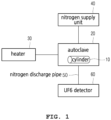
- In the vaporization process, as shown in
FIG. 1 , after charging acylinder 10 filled with UF6 into anautoclave 20, and connecting the UF6 gas transfer pipe (not shown) to thecylinder 10, an inside of theautoclave 20 is heated to about 115°C to vaporize UF6, and UF6 is transferred to a reaction unit (not shown) in a subsequent process. - At this time, nitrogen gas is introduced into the
autoclave 20 through a nitrogen supply pipe from anitrogen supply unit 40, and the nitrogen gas is heated by theheater 30 to heat thecylinder 10 and then discharged through anitrogen discharge pipe 50. - When UF6 leaks to out of the
cylinder 10, the pipe, or process facilities during this process, it has a significant impact on safety of workers and the facilities due to generation of hydrogen fluoride (HF) that is a very toxic material in addition to uranium that is not only a radioactive material but also heavy metal. - That is, when UF6 leaks and is exposed to the air, it reacts with water vapor in the air as follows to produce uranyl fluoride (UO2F2) or uranium oxyfluoride (F2OU), and hydrogen fluoride (HF).
UF6(g) + 2H2O(g) → UO2F2(s) + 4HF(g)
- In addition, UO2F2 dissolves rapidly upon contact with water and generates HF as follows.
UO2F2(s) + nH2O(l) → UO22+(aq) + 2F-(aq)
2F-(aq) + 2H2O(l) ↔ 2HF(aq) + 2OH-(aq)
- A UF6 detector 60 configured to sense a leakage of UF6 in the vaporization process is installed at the
nitrogen discharge pipe 50 and is able to sense whether UF6 leaks by sensing HF generated through the above reaction equations. - That is, in the case of a leak of UF6 inside the
autoclave 20, the gas discharged through thenitrogen discharge pipe 50 reacts when passing through the UF6 detector 60 with outside air that is injected into the UF6 detector 60 to generate HF. At this time, the UF6 detector 60 senses HF so that the administrator may recognize whether the UF6 leaks. - In this process, the above-described system for sensing a UF6 gas leak has a problem in that since a
sensor 61 of the UF6 detector 60 directly contacts highly corrosive HF, thesensor 61 corrodes. In addition, the above-described system has a problem in that UO2F2 is also deposited on the sensor. - In order to minimize such problems, as shown in
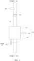
FIG 2 , abypass pipe 51 having an inner diameter smaller than an inner diameter of thenitrogen discharge pipe 50 is installed at thenitrogen discharge pipe 50, and theUF6 detector 60 is installed at thebypass pipe 51. As a result, the flow of gas flowing into theUF6 detector 60 may be minimized, thus minimizing damage to theUF6 detector 60. However, there is a problem in that a structure becomes complicated because a separate nitrogen purge line is required to be built and the like. - In addition, there is a problem that the conduit of the
bypass pipe 51 is narrow, whereby the conduit is blocked due to UO2F2. - In addition, since the gas discharged through the
nitrogen discharge pipe 50 is a high-temperature gas having heated thecylinder 10, there are problems that the gas causes a failure of thesensor 61 of theUF6 detector 60 and shortens a life time of thesensor 61. - Accordingly, there is a problem in that the maintenance of the UF6 detector 60 is troublesome and the maintenance cost is increased.
- In order to resolve such problems, a method of allowing the gas discharged through the
nitrogen discharge pipe 50 to react with water is also proposed, but the problem of thesensor 61 being corroded is not resolved, and there is a problem in that radioactive liquid waste (UO2F2 aqueous solution) is generated. - (Patent Document)
-
Korean Patent No. 10-1227807 WO 2018/008790 A2 - Accordingly, the present disclosure has been made keeping in mind the above problems occurring in the related art, and an objective of the present disclosure is to provide a system for sensing a UF6 gas leak in a nuclear fuel manufacturing process, wherein, in the case of a leakage of a UF6 gas, the system allows UF6 to react with UO2F2 and HF by mixing outside air with the gas discharged through a nitrogen discharge pipe and senses whether UF6 gas leaks by measuring UO2F2 particles, a reaction product, in a non-contact manner. As a result, the system can prevent sensor failure and reduce a maintenance cost of the detector.
- In order to accomplish the above objective, the present invention provides a system for sensing a UF6 gas leak in a nuclear fuel manufacturing process according to claim 1. The system includes: an autoclave provided with a cylinder, charged with uranium hexafluoride (UF6) in a solid state, disposed therein and with a nitrogen supply pipe and a nitrogen discharge pipe, through which nitrogen inflow and nitrogen discharge are accomplished, installed on one side and an opposite side, respectively, and vaporizing the UF6 inside the cylinder through heating the nitrogen inside the autoclave; and a detection unit configured to sense whether the UF6 is mixed with the nitrogen discharged after circulating inside the autoclave, thereby sensing whether the UF6 leaks inside the autoclave, wherein the detection unit generates UO2F2 and HF by allowing UF6 to react with outside air and comprises a measuring instrument, and optically sense the generated UO2F2 particles in a solid state, to allow non-contact UF6 leak detection to be made.
- At this time, the detection unit may include: an outside air injection pipe configured to inject outside air to be mixed with nitrogen, which is discharged from the autoclave to the nitrogen discharge pipe; and the measuring instrument configured to sense UO2F2 generated when the UF6 leaks.
- In addition, the nitrogen discharge pipe may be provided with a filter configured to filter out the UO2F2 having passed through the detection unit.
- In addition, the nitrogen discharge pipe may be provided with an HF sensor configured to sense the HF having passed through the detection unit.
- In addition, the measuring instrument may be a device configured to optically sense particles floating in the air.
- A system for sensing a UF6 gas leak in a nuclear fuel manufacturing process according to the present disclosure has the following effects.
- First, there is an effect of simplifying a configuration of the system for sensing a UF6 gas leak by omitting a complicated configuration such as a bypass pipe and the like.
- Second, since there is no need for direct contact between the gas discharged from an autoclave and a detection device (measuring instrument), there is an effect of preventing damage to the detection device even when there is a leak of UF6 gas.
- That is, the system is a non-contact type that senses UF6 leakage by optically sensing solid particles of UO2F2 generated through the reaction between UF6 and outside air, so damage to the detection device due to corrosion and high temperature can be prevented so that a mechanical life time of the detection device can be extended, whereby there is an effect of reducing maintenance cost.
-
-
FIG. 1 is a view showing a configuration of a UF6 vaporization process in a nuclear fuel manufacturing process. -
FIG. 2 is a view of a main part showing a detector for sensing whether UF6 leaks in a UF6 vaporization process in a nuclear fuel manufacturing process according to a related art. -
FIG. 3 is a view showing a main part of a system for sensing a UF6 gas leak in a nuclear fuel manufacturing process according to an exemplary embodiment of the present invention. -
FIG. 4 is a view showing a configuration of the system for sensing a UF6 gas leak in the nuclear fuel manufacturing process according to the exemplary embodiment of the present invention. -
FIG. 5 is a flow chart showing a process in which detection of UF6, generated during the nuclear fuel manufacturing process according to the exemplary embodiment of the present invention, is accomplished through the system for sensing a UF6 gas leak. - Terms and words used in present specification and claims are not limited to a conventional or dictionary meaning and should be interpreted as having a meaning and concept consistent with the technical idea of the present disclosure on the basis of the principle that an inventor may appropriately define a concept of terms in order to describe the disclosure in the best way.
- Hereinafter, a system for sensing a UF6 gas leak in a nuclear fuel manufacturing process according to an exemplary embodiment of the present invention will be described with reference to
FIGS. 3 and4 . - Prior to the description, since a configuration and an operation of an
autoclave 20 is a well-known technology, a detailed illustration and description will be omitted. - The system for sensing a UF6 gas leak in the nuclear fuel manufacturing process is configured, as shown in
FIGS. 3 and4 , to include adetection unit 100 and afilter 200 and may include anHF sensor 300. - The
detection unit 100 serves to sense in a non-contact manner whether UF6 is contained in nitrogen discharged from theautoclave 20 and is installed at anitrogen discharge pipe 50. - The
detection unit 100 may be installed at a main pipe of thenitrogen discharge pipe 50 as shown inFIG. 4 . - As the
detection unit 100 is installed at thenitrogen discharge pipe 50, nitrogen discharged through thenitrogen discharge pipe 50 is discharged via thedetection unit 100. - The
detection unit 100 allows the nitrogen discharged from theautoclave 20 to react with the outside air, thereby sensing whether or not UF6 leaks. - That is, when UF6 is contained in the gas discharged through the
nitrogen discharge pipe 50, the UF6 generates UO2F2 and HF while reacting with outside air in thedetection unit 100. - To this end, the
detection unit 100 includes areaction unit 110 providing a reaction space, an outsideair injection pipe 120, which is a conduit through which injection of the outside air into thereaction unit 110 is accomplished, and ameasuring instrument 130 for measuring UO2F2 reacted in thereaction unit 110. - The
reaction unit 110 provides a space in which reaction of nitrogen and the outside air is accomplished in the process of discharging the high-temperature nitrogen discharged from theautoclave 20 through thenitrogen discharge pipe 50 as described above and is installed at thenitrogen discharge pipe 50. - In this case, an outside
air injection pipe 120 is installed at thereaction unit 110 so as to allow the outside air to be injected into thereaction unit 110 for the reaction of UF6. - According to the invention, the
measuring instrument 130 serves to measure the UO2F2 generated while the reaction is accomplished in thereaction unit 110. - For the leakage of UF6 gas, while the
sensor 61 electronically senses HF that is in a gaseous state conventionally, the present invention provides a technical configuration for optically measuring UO2F2 that is in a solid state. - That is, in the
reaction unit 110, UO2F2, which is solid particles in a form of fumes, and liquid HF are generated through the reaction of UF6 with outside air. At this time, by optically measuring the solid UO2F2, it is possible to sense whether UF6 gas leaks. - In this case, the
reaction unit 110 is provided of a transparent material so that an inside of thereaction unit 110 may be seen, and the measuringinstrument 130 may be installed outside thereaction unit 110. - Accordingly, the measuring
instrument 130 senses whether the UF6 leaks from the outside of thereaction unit 110 without contacting the material generated in thereaction unit 110. - The measuring
instrument 130 may be provided as a device for optically sensing particles floating in the air. - For example, the measuring
instrument 130 may be provided as a floating particle counter or a photosensor. - Next, the
filter 200 serves to filter out the UO2F2 discharged through thenitrogen discharge pipe 50, thereby preventing the conduit of thenitrogen discharge pipe 50 from being blocked. - That is, when UF6 is contained in the nitrogen discharged through the
nitrogen discharge pipe 50, the conduit of thenitrogen discharge pipe 50 may be blocked by the UO2F2 due to the generation of UO2F2, so UO2F2 is filtered through thefilter 200, whereby the conduit of thenitrogen discharge pipe 50 is prevented from being blocked. - Accordingly, even when there is a leak of UF6, UO2F2 particles pass through the
detection unit 100 and are filtered by thefilter 200, and only nitrogen and HF are discharged passing through thefilter 200. - Next, the
HF sensor 300 serves to sense the HF passing through thefilter 200. - The
HF sensor 300 plays an auxiliary role in sensing whether UF6 leaks. - That is, the present invention optically senses UO2F2 particles through the measuring
instrument 130, but when installation of theHF sensor 300 is parallelly established, even when a malfunction or failure of the measuringinstrument 130 occurs, it may sense whether UF6 leaks through theHF sensor 300. - Hereinafter, a process of sensing a UF6 leak is accomplished by the system for sensing a UF6 gas leak in the nuclear fuel manufacturing process configured as described above will be described with reference to
FIG. 5 . - The vaporization process is performed in S100 through the
autoclave 20 of the nuclear fuel reconversion process. - Nitrogen is introduced into the
autoclave 20, and the nitrogen heated by theheater 30 heats thecylinder 10 filled with solid UF6 to vaporize UF6. - Thereafter, the gas vaporized in the
cylinder 10 is transferred to a subsequent process. - Next, the nitrogen that heated the
cylinder 10 while circulating in theautoclave 20 is discharged in S200 through thenitrogen discharge pipe 50. - At this time, the nitrogen is discharged through the
reaction unit 110 of thedetection unit 100 whereas the outside air is introduced into thereaction unit 110 in S300 through the outsideair inlet pipe 120. - Accordingly, the outside air and nitrogen are mixed in the
reaction unit 110. - At this time, when UF6 leaks and being discharged with nitrogen together, UO2F2 and HF are generated in S400 through the above-described reaction equations.
- At this time, UO2F2 is a particle in a solid state and is sensed in S500 through the measuring
instrument 130 installed outside thereaction unit 110. - In this way, when UO2F2 is sensed through the measuring
instrument 130, the administrator is able to quickly recognize it through an alarm or light emission of warning light to perform a series of post-processing. - Meanwhile, the UO2F2 and HF reacted in the
reaction unit 110 are continuously discharged along thenitrogen discharge pipe 50. - At this time, UO2F2 is filtered out in S600 through the
filter 200, and nitrogen and HF are discharged through thefilter 200. - At this time, the
HF sensor 300 senses in S700 the HF transferred through thenitrogen discharge pipe 50 and let the manager recognize it. - When the UO2F2 is detected through the measuring
instrument 130, the HF will be detected also through theHF sensor 300. - Even when the UO2F2 is not detected due to the failure of the measuring
instrument 130, the UF6 detection error does not occur as theHF sensor 300 senses the HF. - Hereby, the process of sensing the UF6 leak is completed.
- As described so far, the system for sensing a UF6 gas leak according to the present disclosure may sense whether UF6 leaks through the optical detection of the UO2F2 by generating the UO2F2 particles in a solid state through the reaction with the outside air.
- As the UF6 leak detection is performed through such a non-contact method, damage to the detection apparatus may be prevented, and the maintenance cost of the detection apparatus may be reduced.
- In the above, the present invention has been described in detail with respect to the described embodiments, but it is obvious to those skilled in the art that various alterations and modifications are possible within the scope of the invention, which is defined in the appended claims.
-
100: detection unit 110: reaction unit 120: outside air injection pipe 130: measuring instrument 200: filter 300: HF sensor
Claims (5)
- A system for sensing a UF6 gas leak in a nuclear fuel manufacturing process, the system comprising:an autoclave (20) provided with a cylinder (10), charged with uranium hexafluoride (UF6) in a solid state, disposed therein, the autoclave (20) further comprising a nitrogen supply pipe configured to provide a nitrogen inflow into the autoclave (20) and a nitrogen discharge pipe (50) configured for nitrogen discharge from the autoclave (20), wherein said nitrogen supply pipe and said nitrogen discharge pipe are installed on one side and an opposite side of the autoclave, respectively, wherein the autoclave (20) is configured to vaporize the UF6 inside the cylinder (10) through heating the nitrogen inside the autoclave (20); anda detection unit (100) installed at the nitrogen discharge pipe (50), such that nitrogen discharged through the nitrogen discharge pipe (50) is discharged via the detection unit (100), wherein the detection unit(100) is configured to sense whether the UF6 is mixed with the nitrogen discharged after circulating inside the autoclave (20), thereby sensing whether the UF6 leaks inside the autoclave (20),wherein the detection unit (100) is adapted to generate UO2F2 and HF by reacting UF6 with outside air and wherein the detection unit (100) comprises a measuring instrument (130),characterized in that the measuring instrument (130) is configured to optically sense the generated UO2F2 particles in a solid state, to allow non-contact UF6 leak detection to be made.
- The system of claim 1, wherein the detection unit (100) comprises:
an outside air injection pipe (120) configured to inject outside air to be mixed with nitrogen, which is discharged from the autoclave (20) to the nitrogen discharge pipe (50). - The system of claim 1 or 2, wherein the nitrogen discharge pipe (50) is provided with a filter (200) configured to filter out the UO2F2 having passed through the detection unit (100).
- The system of claim 1 or 2, wherein the nitrogen discharge pipe (50) is provided with an HF sensor (300) configured to sense the HF having passed through the detection unit (100).
- The system of claim 1 or 2, wherein the measuring instrument (130) is a device configured to optically sense particles floating in the air.
Applications Claiming Priority (2)
| Application Number | Priority Date | Filing Date | Title |
|---|---|---|---|
| KR1020180073540A KR102065771B1 (en) | 2018-06-26 | 2018-06-26 | UF6 leakage detecting system for the nuclear fuel fabrication |
| PCT/KR2018/009388 WO2020004707A1 (en) | 2018-06-26 | 2018-08-16 | System for sensing uf6 gas leak in nuclear fuel manufacturing process |
Publications (3)
| Publication Number | Publication Date |
|---|---|
| EP3816602A1 EP3816602A1 (en) | 2021-05-05 |
| EP3816602A4 EP3816602A4 (en) | 2022-03-09 |
| EP3816602B1 true EP3816602B1 (en) | 2025-03-19 |
Family
ID=68985114
Family Applications (1)
| Application Number | Title | Priority Date | Filing Date |
|---|---|---|---|
| EP18924411.4A Active EP3816602B1 (en) | 2018-06-26 | 2018-08-16 | System for sensing uf6 gas leak in nuclear fuel manufacturing process |
Country Status (5)
| Country | Link |
|---|---|
| US (1) | US11721446B2 (en) |
| EP (1) | EP3816602B1 (en) |
| JP (2) | JP2021529307A (en) |
| KR (1) | KR102065771B1 (en) |
| WO (1) | WO2020004707A1 (en) |
Families Citing this family (1)
| Publication number | Priority date | Publication date | Assignee | Title |
|---|---|---|---|---|
| CN119959466B (en) * | 2024-12-28 | 2025-11-25 | 中国辐射防护研究院 | A uranium hexafluoride leakage experimental device based on a polygonal prism |
Family Cites Families (17)
| Publication number | Priority date | Publication date | Assignee | Title |
|---|---|---|---|---|
| JPS5969433A (en) * | 1982-10-07 | 1984-04-19 | Toshiba Corp | Safety device of cylinder vessel of uranium hexafluoride |
| US4742009A (en) * | 1985-07-03 | 1988-05-03 | The United States Of America As Represented By The United States Department Of Energy | Method for monitoring stack gases for uranium activity |
| JPH1053419A (en) * | 1996-08-07 | 1998-02-24 | Mitsubishi Materials Corp | Method for treating exhaust gas containing uranium hexafluoride |
| JP3427657B2 (en) * | 1997-01-24 | 2003-07-22 | 三菱マテリアル株式会社 | Inspection method for uranium hexafluoride gas leakage |
| FR2771725B1 (en) * | 1997-11-28 | 2000-02-04 | Franco Belge Combustibles | PROCESS AND DEVICE FOR DIRECT CONVERSION OF URANIUM Hexafluoride to URANIUM OXIDE |
| FR2788760B1 (en) * | 1999-01-27 | 2001-03-23 | Cogema | HEAT TRANSFER SYSTEM FOR UF6 CONVERSION REACTOR IN URANIUM OXIDE |
| JP2001235587A (en) * | 2000-02-22 | 2001-08-31 | Katsuo Ebara | Sealing performance measuring and leakage detecting device for uranium hexafluoride transport material |
| JP3974462B2 (en) * | 2002-06-26 | 2007-09-12 | 核燃料サイクル開発機構 | Rotary kiln for uranium dioxide production |
| KR100840687B1 (en) * | 2006-10-27 | 2008-06-24 | 한국과학기술원 | Leak Detection Method of Enclosed Structures |
| US8659664B2 (en) * | 2007-03-23 | 2014-02-25 | Flir Systems, Inc. | Thermography camera configured for leak detection |
| KR101227807B1 (en) | 2011-02-17 | 2013-01-29 | 한국수력원자력 주식회사 | Apparatus and method for detecting leakage location |
| JP2013007697A (en) * | 2011-06-27 | 2013-01-10 | Hitachi-Ge Nuclear Energy Ltd | Uranium refining equipment and method for refining uranium |
| KR101548973B1 (en) | 2012-03-30 | 2015-09-04 | 최경복 | Sanitary beverage can |
| KR20150067425A (en) * | 2013-12-10 | 2015-06-18 | 주식회사 오리온이엔씨 | System for monitering fissile materials through automatically detecting radiation |
| KR101648973B1 (en) * | 2016-04-28 | 2016-08-18 | 한전원자력연료 주식회사 | The method for recovering uranium from uranium hexafluoride cylinder washing wastewater |
| WO2018008790A2 (en) * | 2016-07-08 | 2018-01-11 | 한전원자력연료 주식회사 | System and method for detecting uranium hexafluoride (uf6) leak |
| KR101856467B1 (en) * | 2017-06-01 | 2018-05-11 | 한전원자력연료 주식회사 | The method and apparatus for residue recovery in uranium hexafluoride cylinders by gas phase reaction |
-
2018
- 2018-06-26 KR KR1020180073540A patent/KR102065771B1/en active Active
- 2018-08-16 EP EP18924411.4A patent/EP3816602B1/en active Active
- 2018-08-16 WO PCT/KR2018/009388 patent/WO2020004707A1/en not_active Ceased
- 2018-08-16 JP JP2020570875A patent/JP2021529307A/en active Pending
-
2020
- 2020-12-23 US US17/132,680 patent/US11721446B2/en active Active
-
2022
- 2022-12-28 JP JP2022211538A patent/JP7394204B2/en active Active
Also Published As
| Publication number | Publication date |
|---|---|
| JP2023052158A (en) | 2023-04-11 |
| US11721446B2 (en) | 2023-08-08 |
| KR102065771B1 (en) | 2020-01-13 |
| EP3816602A4 (en) | 2022-03-09 |
| JP7394204B2 (en) | 2023-12-07 |
| US20210280328A1 (en) | 2021-09-09 |
| KR20200001062A (en) | 2020-01-06 |
| JP2021529307A (en) | 2021-10-28 |
| EP3816602A1 (en) | 2021-05-05 |
| WO2020004707A1 (en) | 2020-01-02 |
Similar Documents
| Publication | Publication Date | Title |
|---|---|---|
| US12154697B2 (en) | Anti-proliferation safeguards for nuclear fuel salts | |
| EP3822987B1 (en) | Molten salt reactor facility | |
| EP3453027B1 (en) | Nuclear fuel salts | |
| US20160118149A1 (en) | Emission monitoring system for a venting system of a nuclear power plant and nuclear power plant having the emission monitoring system | |
| US11721446B2 (en) | System for sensing UF6 gas leak in nuclear fuel manufacturing process | |
| CN110931140B (en) | Device for measuring leakage rate of primary circuit of water-cooled reactor and working method thereof | |
| Lindauer | PROCESSING OF THE MSRE FLUSH AND FUEL SALTS. | |
| Lim et al. | Accuracy and error in measuring residual water mass quantity in spent nuclear fuel canisters after vacuum drying | |
| Ayer et al. | Nuclear fuel cycle facility accident analysis handbook | |
| Ishida et al. | Hydrazine and hydrogen co-injection to mitigate stress corrosion cracking of structural materials in boiling water reactors,(I) temperature dependence of hydrazine reactions | |
| Lindauer | Msre design and operations report. part vii. fuel handling and processing plant | |
| Offutt et al. | FIRST ZIRCONIUM ALLOYED FUEL REPROCESSING CAMPAIGN USING SOLUBLE NUCLEAR POISON. | |
| RU2622107C1 (en) | Method of inspection of the fuel collision of the shells of fuels of the worked heat-fuel assembly of transport nuclear energy installations | |
| JPH06167596A (en) | Corrosion suppression method and device for reactor primary system structure material | |
| Bower | CHEMICAL PROCESSING TECHNOLOGY QUARTERLY PROGRESS REPORT, JANUARY-MARCH 1961 | |
| Chiao et al. | Analyses of postulated ALMR containment and steam generator building accidents using the CONTAIN-LMR code | |
| Kim et al. | Development of Design Requirements for Chemical Injection and Decomposition&Treatment Facility | |
| Savage et al. | IN-PILE LOOP IRRADIATION OF AQUEOUS THORIA-URANIA SLURRY AT ELEVATED TEMPERATURE. DESIGN AND IN-PILE OPERATION OF LOOP L-2-27S | |
| Hyder et al. | Explosion in the Tomsk-7 reprocessing plant on April 6, 1993 | |
| Lerch et al. | Treatment of alpha-bearing combustible wastes using acid digestion | |
| EP4618105A1 (en) | A method of operating a molten salt reactor | |
| Hogg et al. | Development of processes and equipment for recovering uranium from Rover-fuels-burner ash | |
| Yip et al. | Dissolution in HTGR fuel reprocessing: interim development report | |
| Washiya et al. | Continuous-Operation Test at Engineering Scale Uranium Crystallizer System | |
| Ruther et al. | EBR-II experience with sodium cleaning and radioactivity decontamination |
Legal Events
| Date | Code | Title | Description |
|---|---|---|---|
| STAA | Information on the status of an ep patent application or granted ep patent |
Free format text: STATUS: THE INTERNATIONAL PUBLICATION HAS BEEN MADE |
|
| PUAI | Public reference made under article 153(3) epc to a published international application that has entered the european phase |
Free format text: ORIGINAL CODE: 0009012 |
|
| STAA | Information on the status of an ep patent application or granted ep patent |
Free format text: STATUS: REQUEST FOR EXAMINATION WAS MADE |
|
| 17P | Request for examination filed |
Effective date: 20201228 |
|
| AK | Designated contracting states |
Kind code of ref document: A1 Designated state(s): AL AT BE BG CH CY CZ DE DK EE ES FI FR GB GR HR HU IE IS IT LI LT LU LV MC MK MT NL NO PL PT RO RS SE SI SK SM TR |
|
| DAV | Request for validation of the european patent (deleted) | ||
| DAX | Request for extension of the european patent (deleted) | ||
| REG | Reference to a national code |
Ref country code: DE Free format text: PREVIOUS MAIN CLASS: G01M0003380000 Ref country code: DE Ref legal event code: R079 Ref document number: 602018080371 Country of ref document: DE Free format text: PREVIOUS MAIN CLASS: G01M0003380000 Ipc: G21C0017000000 |
|
| A4 | Supplementary search report drawn up and despatched |
Effective date: 20220208 |
|
| RIC1 | Information provided on ipc code assigned before grant |
Ipc: G01M 3/20 20060101ALI20220202BHEP Ipc: G01M 3/38 20060101ALI20220202BHEP Ipc: G21C 21/00 20060101ALI20220202BHEP Ipc: G21C 17/00 20060101AFI20220202BHEP |
|
| GRAP | Despatch of communication of intention to grant a patent |
Free format text: ORIGINAL CODE: EPIDOSNIGR1 |
|
| STAA | Information on the status of an ep patent application or granted ep patent |
Free format text: STATUS: GRANT OF PATENT IS INTENDED |
|
| INTG | Intention to grant announced |
Effective date: 20241018 |
|
| RAP3 | Party data changed (applicant data changed or rights of an application transferred) |
Owner name: KEPCO NUCLEAR FUEL CO., LTD. |
|
| GRAS | Grant fee paid |
Free format text: ORIGINAL CODE: EPIDOSNIGR3 |
|
| GRAA | (expected) grant |
Free format text: ORIGINAL CODE: 0009210 |
|
| STAA | Information on the status of an ep patent application or granted ep patent |
Free format text: STATUS: THE PATENT HAS BEEN GRANTED |
|
| AK | Designated contracting states |
Kind code of ref document: B1 Designated state(s): AL AT BE BG CH CY CZ DE DK EE ES FI FR GB GR HR HU IE IS IT LI LT LU LV MC MK MT NL NO PL PT RO RS SE SI SK SM TR |
|
| REG | Reference to a national code |
Ref country code: GB Ref legal event code: FG4D |
|
| REG | Reference to a national code |
Ref country code: CH Ref legal event code: EP |
|
| REG | Reference to a national code |
Ref country code: DE Ref legal event code: R096 Ref document number: 602018080371 Country of ref document: DE |
|
| REG | Reference to a national code |
Ref country code: IE Ref legal event code: FG4D |
|
| PG25 | Lapsed in a contracting state [announced via postgrant information from national office to epo] |
Ref country code: RS Free format text: LAPSE BECAUSE OF FAILURE TO SUBMIT A TRANSLATION OF THE DESCRIPTION OR TO PAY THE FEE WITHIN THE PRESCRIBED TIME-LIMIT Effective date: 20250619 |
|
| PG25 | Lapsed in a contracting state [announced via postgrant information from national office to epo] |
Ref country code: FI Free format text: LAPSE BECAUSE OF FAILURE TO SUBMIT A TRANSLATION OF THE DESCRIPTION OR TO PAY THE FEE WITHIN THE PRESCRIBED TIME-LIMIT Effective date: 20250319 |
|
| REG | Reference to a national code |
Ref country code: LT Ref legal event code: MG9D |
|
| PG25 | Lapsed in a contracting state [announced via postgrant information from national office to epo] |
Ref country code: NO Free format text: LAPSE BECAUSE OF FAILURE TO SUBMIT A TRANSLATION OF THE DESCRIPTION OR TO PAY THE FEE WITHIN THE PRESCRIBED TIME-LIMIT Effective date: 20250619 |
|
| PG25 | Lapsed in a contracting state [announced via postgrant information from national office to epo] |
Ref country code: HR Free format text: LAPSE BECAUSE OF FAILURE TO SUBMIT A TRANSLATION OF THE DESCRIPTION OR TO PAY THE FEE WITHIN THE PRESCRIBED TIME-LIMIT Effective date: 20250319 |
|
| PG25 | Lapsed in a contracting state [announced via postgrant information from national office to epo] |
Ref country code: LV Free format text: LAPSE BECAUSE OF FAILURE TO SUBMIT A TRANSLATION OF THE DESCRIPTION OR TO PAY THE FEE WITHIN THE PRESCRIBED TIME-LIMIT Effective date: 20250319 |
|
| PG25 | Lapsed in a contracting state [announced via postgrant information from national office to epo] |
Ref country code: GR Free format text: LAPSE BECAUSE OF FAILURE TO SUBMIT A TRANSLATION OF THE DESCRIPTION OR TO PAY THE FEE WITHIN THE PRESCRIBED TIME-LIMIT Effective date: 20250620 Ref country code: BG Free format text: LAPSE BECAUSE OF FAILURE TO SUBMIT A TRANSLATION OF THE DESCRIPTION OR TO PAY THE FEE WITHIN THE PRESCRIBED TIME-LIMIT Effective date: 20250319 |
|
| REG | Reference to a national code |
Ref country code: NL Ref legal event code: MP Effective date: 20250319 |
|
| REG | Reference to a national code |
Ref country code: AT Ref legal event code: MK05 Ref document number: 1777680 Country of ref document: AT Kind code of ref document: T Effective date: 20250319 |
|
| PG25 | Lapsed in a contracting state [announced via postgrant information from national office to epo] |
Ref country code: NL Free format text: LAPSE BECAUSE OF FAILURE TO SUBMIT A TRANSLATION OF THE DESCRIPTION OR TO PAY THE FEE WITHIN THE PRESCRIBED TIME-LIMIT Effective date: 20250319 |
|
| PG25 | Lapsed in a contracting state [announced via postgrant information from national office to epo] |
Ref country code: SE Free format text: LAPSE BECAUSE OF FAILURE TO SUBMIT A TRANSLATION OF THE DESCRIPTION OR TO PAY THE FEE WITHIN THE PRESCRIBED TIME-LIMIT Effective date: 20250319 |
|
| PG25 | Lapsed in a contracting state [announced via postgrant information from national office to epo] |
Ref country code: SM Free format text: LAPSE BECAUSE OF FAILURE TO SUBMIT A TRANSLATION OF THE DESCRIPTION OR TO PAY THE FEE WITHIN THE PRESCRIBED TIME-LIMIT Effective date: 20250319 |
|
| PG25 | Lapsed in a contracting state [announced via postgrant information from national office to epo] |
Ref country code: PT Free format text: LAPSE BECAUSE OF FAILURE TO SUBMIT A TRANSLATION OF THE DESCRIPTION OR TO PAY THE FEE WITHIN THE PRESCRIBED TIME-LIMIT Effective date: 20250721 Ref country code: ES Free format text: LAPSE BECAUSE OF FAILURE TO SUBMIT A TRANSLATION OF THE DESCRIPTION OR TO PAY THE FEE WITHIN THE PRESCRIBED TIME-LIMIT Effective date: 20250319 |
|
| PGFP | Annual fee paid to national office [announced via postgrant information from national office to epo] |
Ref country code: DE Payment date: 20250819 Year of fee payment: 8 |
|
| PG25 | Lapsed in a contracting state [announced via postgrant information from national office to epo] |
Ref country code: PL Free format text: LAPSE BECAUSE OF FAILURE TO SUBMIT A TRANSLATION OF THE DESCRIPTION OR TO PAY THE FEE WITHIN THE PRESCRIBED TIME-LIMIT Effective date: 20250319 Ref country code: IT Free format text: LAPSE BECAUSE OF FAILURE TO SUBMIT A TRANSLATION OF THE DESCRIPTION OR TO PAY THE FEE WITHIN THE PRESCRIBED TIME-LIMIT Effective date: 20250319 |
|
| PGFP | Annual fee paid to national office [announced via postgrant information from national office to epo] |
Ref country code: GB Payment date: 20250821 Year of fee payment: 8 |
|
| PG25 | Lapsed in a contracting state [announced via postgrant information from national office to epo] |
Ref country code: AT Free format text: LAPSE BECAUSE OF FAILURE TO SUBMIT A TRANSLATION OF THE DESCRIPTION OR TO PAY THE FEE WITHIN THE PRESCRIBED TIME-LIMIT Effective date: 20250319 |
|
| PGFP | Annual fee paid to national office [announced via postgrant information from national office to epo] |
Ref country code: FR Payment date: 20250821 Year of fee payment: 8 |
|
| PG25 | Lapsed in a contracting state [announced via postgrant information from national office to epo] |
Ref country code: CZ Free format text: LAPSE BECAUSE OF FAILURE TO SUBMIT A TRANSLATION OF THE DESCRIPTION OR TO PAY THE FEE WITHIN THE PRESCRIBED TIME-LIMIT Effective date: 20250319 Ref country code: EE Free format text: LAPSE BECAUSE OF FAILURE TO SUBMIT A TRANSLATION OF THE DESCRIPTION OR TO PAY THE FEE WITHIN THE PRESCRIBED TIME-LIMIT Effective date: 20250319 |
|
| PG25 | Lapsed in a contracting state [announced via postgrant information from national office to epo] |
Ref country code: RO Free format text: LAPSE BECAUSE OF FAILURE TO SUBMIT A TRANSLATION OF THE DESCRIPTION OR TO PAY THE FEE WITHIN THE PRESCRIBED TIME-LIMIT Effective date: 20250319 |
|
| PG25 | Lapsed in a contracting state [announced via postgrant information from national office to epo] |
Ref country code: SK Free format text: LAPSE BECAUSE OF FAILURE TO SUBMIT A TRANSLATION OF THE DESCRIPTION OR TO PAY THE FEE WITHIN THE PRESCRIBED TIME-LIMIT Effective date: 20250319 |
|
| PG25 | Lapsed in a contracting state [announced via postgrant information from national office to epo] |
Ref country code: IS Free format text: LAPSE BECAUSE OF FAILURE TO SUBMIT A TRANSLATION OF THE DESCRIPTION OR TO PAY THE FEE WITHIN THE PRESCRIBED TIME-LIMIT Effective date: 20250719 |
|
| REG | Reference to a national code |
Ref country code: DE Ref legal event code: R097 Ref document number: 602018080371 Country of ref document: DE |
|
| PG25 | Lapsed in a contracting state [announced via postgrant information from national office to epo] |
Ref country code: DK Free format text: LAPSE BECAUSE OF FAILURE TO SUBMIT A TRANSLATION OF THE DESCRIPTION OR TO PAY THE FEE WITHIN THE PRESCRIBED TIME-LIMIT Effective date: 20250319 |
|
| PLBE | No opposition filed within time limit |
Free format text: ORIGINAL CODE: 0009261 |
|
| STAA | Information on the status of an ep patent application or granted ep patent |
Free format text: STATUS: NO OPPOSITION FILED WITHIN TIME LIMIT |
|
| REG | Reference to a national code |
Ref country code: CH Ref legal event code: L10 Free format text: ST27 STATUS EVENT CODE: U-0-0-L10-L00 (AS PROVIDED BY THE NATIONAL OFFICE) Effective date: 20260128 |
|
| 26N | No opposition filed |
Effective date: 20251222 |
|
| REG | Reference to a national code |
Ref country code: CH Ref legal event code: H13 Free format text: ST27 STATUS EVENT CODE: U-0-0-H10-H13 (AS PROVIDED BY THE NATIONAL OFFICE) Effective date: 20260324 |
|
| PG25 | Lapsed in a contracting state [announced via postgrant information from national office to epo] |
Ref country code: MC Free format text: LAPSE BECAUSE OF FAILURE TO SUBMIT A TRANSLATION OF THE DESCRIPTION OR TO PAY THE FEE WITHIN THE PRESCRIBED TIME-LIMIT Effective date: 20250319 |
|
| PG25 | Lapsed in a contracting state [announced via postgrant information from national office to epo] |
Ref country code: LU Free format text: LAPSE BECAUSE OF NON-PAYMENT OF DUE FEES Effective date: 20250816 |
|
| PG25 | Lapsed in a contracting state [announced via postgrant information from national office to epo] |
Ref country code: CH Free format text: LAPSE BECAUSE OF NON-PAYMENT OF DUE FEES Effective date: 20250831 |