EP3816489A1 - Seal ring - Google Patents
Seal ring Download PDFInfo
- Publication number
- EP3816489A1 EP3816489A1 EP19803913.3A EP19803913A EP3816489A1 EP 3816489 A1 EP3816489 A1 EP 3816489A1 EP 19803913 A EP19803913 A EP 19803913A EP 3816489 A1 EP3816489 A1 EP 3816489A1
- Authority
- EP
- European Patent Office
- Prior art keywords
- seal ring
- groove
- grooves
- circumferential direction
- sealed fluid
- Prior art date
- Legal status (The legal status is an assumption and is not a legal conclusion. Google has not performed a legal analysis and makes no representation as to the accuracy of the status listed.)
- Granted
Links
Images




Classifications
-
- F—MECHANICAL ENGINEERING; LIGHTING; HEATING; WEAPONS; BLASTING
- F16—ENGINEERING ELEMENTS AND UNITS; GENERAL MEASURES FOR PRODUCING AND MAINTAINING EFFECTIVE FUNCTIONING OF MACHINES OR INSTALLATIONS; THERMAL INSULATION IN GENERAL
- F16J—PISTONS; CYLINDERS; SEALINGS
- F16J15/00—Sealings
- F16J15/16—Sealings between relatively-moving surfaces
- F16J15/18—Sealings between relatively-moving surfaces with stuffing-boxes for elastic or plastic packings
-
- F—MECHANICAL ENGINEERING; LIGHTING; HEATING; WEAPONS; BLASTING
- F16—ENGINEERING ELEMENTS AND UNITS; GENERAL MEASURES FOR PRODUCING AND MAINTAINING EFFECTIVE FUNCTIONING OF MACHINES OR INSTALLATIONS; THERMAL INSULATION IN GENERAL
- F16J—PISTONS; CYLINDERS; SEALINGS
- F16J15/00—Sealings
- F16J15/16—Sealings between relatively-moving surfaces
- F16J15/34—Sealings between relatively-moving surfaces with slip-ring pressed against a more or less radial face on one member
- F16J15/3404—Sealings between relatively-moving surfaces with slip-ring pressed against a more or less radial face on one member and characterised by parts or details relating to lubrication, cooling or venting of the seal
- F16J15/3408—Sealings between relatively-moving surfaces with slip-ring pressed against a more or less radial face on one member and characterised by parts or details relating to lubrication, cooling or venting of the seal at least one ring having an uneven slipping surface
- F16J15/3412—Sealings between relatively-moving surfaces with slip-ring pressed against a more or less radial face on one member and characterised by parts or details relating to lubrication, cooling or venting of the seal at least one ring having an uneven slipping surface with cavities
- F16J15/342—Sealings between relatively-moving surfaces with slip-ring pressed against a more or less radial face on one member and characterised by parts or details relating to lubrication, cooling or venting of the seal at least one ring having an uneven slipping surface with cavities with means for feeding fluid directly to the face
-
- F—MECHANICAL ENGINEERING; LIGHTING; HEATING; WEAPONS; BLASTING
- F16—ENGINEERING ELEMENTS AND UNITS; GENERAL MEASURES FOR PRODUCING AND MAINTAINING EFFECTIVE FUNCTIONING OF MACHINES OR INSTALLATIONS; THERMAL INSULATION IN GENERAL
- F16J—PISTONS; CYLINDERS; SEALINGS
- F16J15/00—Sealings
- F16J15/16—Sealings between relatively-moving surfaces
- F16J15/164—Sealings between relatively-moving surfaces the sealing action depending on movements; pressure difference, temperature or presence of leaking fluid
-
- F—MECHANICAL ENGINEERING; LIGHTING; HEATING; WEAPONS; BLASTING
- F16—ENGINEERING ELEMENTS AND UNITS; GENERAL MEASURES FOR PRODUCING AND MAINTAINING EFFECTIVE FUNCTIONING OF MACHINES OR INSTALLATIONS; THERMAL INSULATION IN GENERAL
- F16J—PISTONS; CYLINDERS; SEALINGS
- F16J15/00—Sealings
- F16J15/16—Sealings between relatively-moving surfaces
- F16J15/18—Sealings between relatively-moving surfaces with stuffing-boxes for elastic or plastic packings
- F16J15/182—Sealings between relatively-moving surfaces with stuffing-boxes for elastic or plastic packings with lubricating, cooling or draining means
-
- F—MECHANICAL ENGINEERING; LIGHTING; HEATING; WEAPONS; BLASTING
- F16—ENGINEERING ELEMENTS AND UNITS; GENERAL MEASURES FOR PRODUCING AND MAINTAINING EFFECTIVE FUNCTIONING OF MACHINES OR INSTALLATIONS; THERMAL INSULATION IN GENERAL
- F16J—PISTONS; CYLINDERS; SEALINGS
- F16J15/00—Sealings
- F16J15/16—Sealings between relatively-moving surfaces
- F16J15/18—Sealings between relatively-moving surfaces with stuffing-boxes for elastic or plastic packings
- F16J15/188—Split assemblies
-
- F—MECHANICAL ENGINEERING; LIGHTING; HEATING; WEAPONS; BLASTING
- F16—ENGINEERING ELEMENTS AND UNITS; GENERAL MEASURES FOR PRODUCING AND MAINTAINING EFFECTIVE FUNCTIONING OF MACHINES OR INSTALLATIONS; THERMAL INSULATION IN GENERAL
- F16J—PISTONS; CYLINDERS; SEALINGS
- F16J15/00—Sealings
- F16J15/16—Sealings between relatively-moving surfaces
- F16J15/32—Sealings between relatively-moving surfaces with elastic sealings, e.g. O-rings
- F16J15/324—Arrangements for lubrication or cooling of the sealing itself
-
- F—MECHANICAL ENGINEERING; LIGHTING; HEATING; WEAPONS; BLASTING
- F16—ENGINEERING ELEMENTS AND UNITS; GENERAL MEASURES FOR PRODUCING AND MAINTAINING EFFECTIVE FUNCTIONING OF MACHINES OR INSTALLATIONS; THERMAL INSULATION IN GENERAL
- F16J—PISTONS; CYLINDERS; SEALINGS
- F16J15/00—Sealings
- F16J15/16—Sealings between relatively-moving surfaces
- F16J15/32—Sealings between relatively-moving surfaces with elastic sealings, e.g. O-rings
- F16J15/3268—Mounting of sealing rings
- F16J15/3272—Mounting of sealing rings the rings having a break or opening, e.g. to enable mounting on a shaft otherwise than from a shaft end
-
- F—MECHANICAL ENGINEERING; LIGHTING; HEATING; WEAPONS; BLASTING
- F16—ENGINEERING ELEMENTS AND UNITS; GENERAL MEASURES FOR PRODUCING AND MAINTAINING EFFECTIVE FUNCTIONING OF MACHINES OR INSTALLATIONS; THERMAL INSULATION IN GENERAL
- F16J—PISTONS; CYLINDERS; SEALINGS
- F16J15/00—Sealings
- F16J15/16—Sealings between relatively-moving surfaces
- F16J15/34—Sealings between relatively-moving surfaces with slip-ring pressed against a more or less radial face on one member
- F16J15/3404—Sealings between relatively-moving surfaces with slip-ring pressed against a more or less radial face on one member and characterised by parts or details relating to lubrication, cooling or venting of the seal
- F16J15/3408—Sealings between relatively-moving surfaces with slip-ring pressed against a more or less radial face on one member and characterised by parts or details relating to lubrication, cooling or venting of the seal at least one ring having an uneven slipping surface
- F16J15/3412—Sealings between relatively-moving surfaces with slip-ring pressed against a more or less radial face on one member and characterised by parts or details relating to lubrication, cooling or venting of the seal at least one ring having an uneven slipping surface with cavities
- F16J15/3416—Sealings between relatively-moving surfaces with slip-ring pressed against a more or less radial face on one member and characterised by parts or details relating to lubrication, cooling or venting of the seal at least one ring having an uneven slipping surface with cavities with at least one continuous groove
-
- F—MECHANICAL ENGINEERING; LIGHTING; HEATING; WEAPONS; BLASTING
- F16—ENGINEERING ELEMENTS AND UNITS; GENERAL MEASURES FOR PRODUCING AND MAINTAINING EFFECTIVE FUNCTIONING OF MACHINES OR INSTALLATIONS; THERMAL INSULATION IN GENERAL
- F16J—PISTONS; CYLINDERS; SEALINGS
- F16J15/00—Sealings
- F16J15/44—Free-space packings
- F16J15/441—Free-space packings with floating ring
Definitions
- the present invention relates to a seal ring used for sealing a clearance between a rotary shaft and a housing, and specifically relates to a seal ring used in a state in which the seal ring is attached to an annular groove, i.e., a so-called stuffing box.
- a seal ring is attached to the outer periphery of a rotary shaft.
- a sliding surface of the seal ring slides in close contact with a sliding surface formed at the rotary shaft, and accordingly, the seal ring seals a clearance between the rotary shaft and a housing to prevent leakage of sealed fluid (e.g., liquid).
- Friction reduction can be accomplished by the technique of generating a dynamic pressure between the sliding surfaces by rotation of the rotary shaft to slide the sliding surfaces with a fluid film of the sealed fluid being interposed.
- a seal ring as described in Patent Citation 1 has been known as the seal ring configured to generate the dynamic pressure between the sliding surfaces by rotation of the rotary shaft.
- the seal ring of Patent Citation 1 is attached to an annular groove provided at the outer periphery of a rotary shaft.
- the seal ring is pressed to a housing side and one side wall surface side of the annular groove by the pressure of high-pressure sealed fluid, and a sliding surface at one side surface of the seal ring slides in close contact with a sliding surface at one side wall surface of the annular groove.
- multiple dynamic pressure grooves opening on an inner diameter side are provided in a circumferential direction.
- the dynamic pressure groove includes a deep groove at the center in the circumferential direction and shallow grooves formed continuously to both sides of the deep groove in the circumferential direction, extending in the circumferential direction, and having bottom surfaces inclined such that the shallow grooves gradually become shallower toward terminal ends.
- the positive pressure increases due to wedge action caused by the inclined bottom surface of the rotation-direction-side shallow groove, and is generated across the entirety of the dynamic pressure groove. Accordingly, the force of slightly separating the sliding surfaces from each other, i.e., so-called buoyancy, is obtained.
- the sliding surfaces are slightly separated from each other, and therefore, the high-pressure sealed fluid flows into a portion between the sliding surfaces from the inner diameter side of the sliding surface and the sealed fluid flows out of the rotation-direction-side shallow grooves generating the positive pressure to the portion between the sliding surfaces.
- a fluid film is formed between the sliding surfaces, and lubricity between the sliding surfaces is maintained.
- Patent Citation 1 JP 9-210211 A (third page, FIG. 3 )
- the sliding surface of the rotary shaft moves relative to the dynamic pressure grooves in the circumferential direction.
- the positive pressure increases as the number of rotations of the rotary shaft increases, and the fluid film is formed between the sliding surfaces to enhance the lubricity of the sliding surface.
- the dynamic pressure groove is configured such that both shallow grooves are positioned on the same circumference with respect to the deep groove.
- cavitation is caused in a region where a great positive pressure and a great negative pressure are generated in the circumferential direction. Due to greater variation in the buoyancy generated across the circumferential direction of the sliding surface, there is a probability that an adverse effect on the fluid film, such as a non-uniform fluid film, is caused and the lubricity becomes unstable.
- the present invention has been made in view of such a problem, and an object of the present invention is to provide a seal ring configured so that stable lubrication performance can be provided across a wide range of rotation speed.
- a seal ring according to the present invention is seal ring for sealing a clearance between a rotary shaft and a housing, including: inclined grooves formed at a sliding surface so as to be arranged in a circumferential direction, the inclined grooves being open on an outer diameter side of the seal ring to generate a drawing pressure; and supply grooves being open on a sealed fluid side of the seal ring and extending in a radially outward direction toward inner diameter sides of the inclined grooves.
- high-pressure sealed fluid introduced through inner-diameter-side openings of the supply grooves is, on the outer diameter side, drawn by the drawing pressure due to a flow in the outer diameter direction in each inclined groove upon rotation of the rotary shaft, and the flow of sealed fluid in the radially outward direction is formed among the supply grooves and the inclined grooves.
- a fluid film can be formed with favorable balance in the circumferential direction among the supply grooves and the inclined grooves, and therefore, stable lubrication performance can be provided across a wide range of rotation speed.
- a seal portion is formed continuously in the circumferential direction and positioned between the supply grooves and the inclined grooves. According to this preferable configuration, the supply grooves and the inclined grooves between which the flow of sealed fluid in a radial direction is formed are separated from each other in the radial direction by the seal portion, and therefore, the fluid film is formed with favorable balance in the circumferential direction on the seal portion.
- the supply grooves are equally arranged in the circumferential direction. According to this preferable configuration, the flow of sealed fluid in the radial direction is formed with favorable balance in the circumferential direction on the seal portion.
- the supply grooves are communicated with each other through a communication groove which is positioned on the inner diameter side of the seal portion and extends in the circumferential direction.
- the high-pressure sealed fluid introduced through the inner-diameter-side openings of the supply grooves is supplied in the circumferential direction by the communication groove, and therefore, the flow of sealed fluid in the radial direction is reliably formed with favorable balance in the circumferential direction on the seal portion.
- the seal ring further comprise dynamic pressure grooves each formed at the sliding surface between adjacent two of the supply grooves in the circumferential direction and being open on the sealed fluid side of the seal ring.
- a negative pressure generated by the inclined grooves can be partially cancelled by a positive pressure generated in the dynamic pressure grooves, and therefore, the flow of sealed fluid in the radial direction is easily formed on the seal portion.
- a seal ring according to a first embodiment will be described with reference to FIGS. 1 to 5 .
- the right side in the plane of paper of FIG. 2 will be described as a sealed fluid side L
- the left side in the plane of paper will be described as an atmosphere side A.
- the fluid pressure of sealed fluid on the sealed fluid side L will be described as a higher pressure than an atmospheric pressure.
- a sliding surface includes a flat surface and a groove recessed as compared to the flat surface.
- the flat surface forming the sliding surface is, in the side views, indicated by the color of white, and the groove forming the sliding surface is indicated by dots.
- the seal ring 1 seals a portion between a rotary shaft 2 and a housing 3 of a rotary machine, the rotary shaft 2 and the housing 3 rotating relative to each other. In this manner, the seal ring 1 partitions the inside of the housing 3 into the sealed fluid side L and the atmosphere side A (see FIG. 2 ), and prevents leakage of the sealed fluid from the sealed fluid side L to the atmosphere side A.
- the rotary shaft 2 and the housing 3 are made of a metal material such as stainless steel.
- the sealed fluid is one used for the purpose of cooling and lubricating, e.g., a not-shown gear and a not-shown bearing provided in a machine chamber of the rotary machine, such as oil.
- the seal ring 1 is a component molded with resin such as PTFE, and is provided with a joint portion 1a at one spot in a circumferential direction to form a C-shape.
- the seal ring 1 is used with the seal ring 1 being attached to an annular groove 20, the annular groove 20 being provided along the outer periphery of the rotary shaft 2 and having a rectangular sectional shape.
- the rotary shaft 2 rotates clockwise as indicated by a white arrow in FIG. 3 , and the seal ring 1 rotates counterclockwise relative to the annular groove 20 of the rotary shaft 2. Note that in FIG. 2 , the section of the seal ring 1 along a radial direction is schematically illustrated.
- the seal ring 1 has a rectangular sectional shape.
- the seal ring 1 is pressed to the atmosphere side A by the fluid pressure of the sealed fluid acting on a side surface on the sealed fluid side L, and accordingly, a sliding surface S1 formed on a side surface 10 (hereinafter sometimes merely referred to as a "side surface 10") side on the atmosphere side A slidably closely contacts a sliding surface S2 on a side wall surface 21 (hereinafter sometimes merely referred to as a "side wall surface 21") side of the annular groove 20 on the atmosphere side A.
- the seal ring 1 in response to stress in an expansion direction due to the fluid pressure of the sealed fluid acting on an inner circumferential surface, the seal ring 1 is pressed in a radially outward direction, and accordingly, an outer circumferential surface 11 closely contacts an inner circumferential surface 31 of a shaft hole 30 of the housing 3.
- sliding surfaces S1, S2 form a substantial sliding region between the side surface 10 of the seal ring 1 and the side wall surface 21 of the annular groove 20 of the rotary shaft 2.
- a non-sliding surface S1' is formed continuously to an outer diameter side of the sliding surface S1 on the side surface 10 side
- a non-sliding surface S2' is formed continuously to an inner diameter side of the sliding surface S2 on the side wall surface 21 side (see FIG. 2 ) .
- the sliding surface S1 formed on the side surface 10 side of the seal ring 1 includes a flat surface 16, multiple supply grooves 13 extending in the radial direction from an inner-diameter-side end portion of the side surface 10, a communication groove 14 communicated with outer-diameter-side end portions of the supply grooves 13 and formed continuously in a substantially annular shape across the joint portion 1a, and multiple inclined grooves 15 formed inclined to the direction of rotation of the rotary shaft 2 from the vicinity of an outer-diameter-side end portion of the communication groove 14 (i.e., an outer-diameter-side end portion of a later-described seal portion 16a) and communicated with an outer-diameter-side end portion of the side surface 10 (on the atmosphere side A).
- an outer-diameter-side end portion of the communication groove 14 i.e., an outer-diameter-side end portion of a later-described seal portion 16a
- the supply grooves 13 are arranged at equal intervals in the circumferential direction of the sliding surface S1, except for the vicinity of the joint portion 1a.
- the inclined grooves 15 extend from the sliding surface S1 to the non-sliding surface S1', and are arranged at equal intervals in the circumferential direction, except for the vicinity of the joint portion 1a.
- the flat surface 16 includes the seal portion 16a positioned between the outer-diameter-side end portion of the communication groove 14 and an inner-diameter-side end portion of each of the multiple inclined grooves 15 and formed continuously in a substantially annular shape across the joint portion 1a, an inner-diameter-side lubrication portion 16b sandwiched by adjacent ones of the supply grooves 13 in the circumferential direction, and an outer-diameter-side lubrication portion 16c sandwiched by adjacent ones of the inclined grooves 15 in the circumferential direction (see FIG. 3 ).
- the dimension of the seal portion 16a in the radial direction is 1/20 (preferably 1/5 to 1/50) of the dimension of the sliding surface S1 in the radial direction, and is the substantially same dimension as the dimension of the outer-diameter-side lubrication portion 16c in the circumferential direction. Note that the dimension of the seal portion 16a in the radial direction is preferably short, considering that the sealed fluid easily moves over the seal portion 16a.
- the supply groove 13 supplies, regardless of rotation/stop of the rotary shaft 2, the sealed fluid to a portion between the sliding surfaces S1, S2 when the sealed fluid has a higher pressure than that of atmospheric air.
- the supply groove 13 has a rectangular shape as viewed from the side.
- the supply groove 13 opens on the inner diameter side (i.e., the sealed fluid side) of the sliding surface S1, and is communicated with the communication groove 14 on the outer diameter side.
- a bottom surface 13d (see FIG. 4A ) of the supply groove 13 is formed flat, and is parallel with the flat surface 16.
- the depth of the supply groove 13 is several tens to several hundreds of ⁇ m and preferably 100 to 200 ⁇ m. Note that the depth of the supply groove 13 may be much deeper (e.g., up to about a depth of 1 mm).
- the communication groove 14 is formed to extend in the circumferential direction at a position on the outer diameter side with respect to the center of the sliding surface S1 in the radial direction, has an arc shape as viewed from the side, and has a shorter dimension in the radial direction than the dimension of the supply groove 13 in the circumferential direction. Moreover, a bottom surface 14d of the communication groove 14 is formed flat, is parallel with the flat surface 16, and is formed continuously to the bottom surface 13d of the supply groove 13. The depth of the communication groove 14 is substantially the same as that of the supply groove 13 (see FIG. 4A ).
- the inclined groove 15 extends to the outer diameter side in the rotation direction of the rotary shaft 2 from the seal portion 16a, i.e., extends inclined with respect to the radial direction, and has the function of generating a drawing pressure in the inclined grooves 15 due to a flow in the radially outward direction upon rotation of the rotary shaft 2.
- the inclined groove 15 is configured such that a closed portion 15d extending along the outer-diameter-side end portion of the seal portion 16a, a planar outer inclined wall portion 15b positioned on an opposite rotation side of the rotary shaft 2 and formed perpendicularly to a bottom surface 15e, a planar inner inclined wall portion 15c positioned on a rotation side of the rotary shaft 2 and formed perpendicularly to the bottom surface 15e, and an opening 15a crossing the outer inclined wall portion 15b and the inner inclined wall portion 15c and communicated with a non-sliding surface S1' side (i.e., the atmosphere side A) form a parallelogram shape as viewed from the side.
- a non-sliding surface S1' side i.e., the atmosphere side A
- the inclined groove 15 has the substantially same dimension in the circumferential direction as the dimension of the communication groove 14 in the radial direction, and has a longer dimension in an extension direction than the dimension in the circumferential direction. Moreover, the bottom surface 15e of the inclined groove 15 is formed flat, and is parallel with the flat surface 16. The depth of the inclined groove 15 is shallower than those of the supply groove 13 and the communication groove 14.
- the outer-diameter-side lubrication portion 16c having a shorter dimension in the circumferential direction than the dimension of the inclined groove 15 in the circumferential direction is interposed between adjacent ones of the inclined grooves 15 in the circumferential direction.
- the dimensions of these portions may be the same as each other, or the outer-diameter-side lubrication portion 16c may have a longer dimension.
- the multiple inclined grooves 15 may be formed with a curvature such that the outer-diameter-side lubrication portions 16c are formed to the outer diameter side with the substantially equal width.
- 4A, 4B , and 5 schematically illustrates an association between an enlarged partial side view of the seal ring 1 as viewed from the side and an A-A sectional view cut along the supply groove 13, the communication groove 14, and the inclined groove 15 of the enlarged partial side view.
- the sealed fluid and air in the inclined grooves 15 move from a closed portion 15d side to an opening 15a side of the inclined groove 15, and accordingly, the drawing pressure is generated from the closed portion 15d side to the opening 15a side of the inclined groove 15.
- a negative pressure is generated on the closed portion 15d side.
- the sealed fluid forming a fluid film on the seal portion 16a is drawn into the inclined grooves 15 by such a negative pressure. Accordingly, the sealed fluid in the communication groove 14 leaks out to a seal portion 16a side, and the flow F of moving the sealed fluid over the seal portion 16a from the communication groove 14 and drawing the sealed fluid into the inclined grooves 15 is formed (see FIG. 5 ).
- the fluid film is reliably formed on the seal portion 16a, and lubricity is enhanced.
- the fluid film of the sealed fluid is formed between the sliding surfaces S1, S2 due to, e.g., the flow F and the resting pressure, and the lubricity is enhanced.
- the multiple inclined grooves 15 are formed at equal intervals across the circumferential direction, and therefore, a dynamic pressure is substantially uniformly generated across the outer diameter side of the sliding surface S1 (i.e., the seal portion 16a). Thus, stable buoyancy can be obtained across the circumferential direction.
- the sealed fluid is mainly supplied from the communication groove 14 to a portion between the sliding surface S2 and the seal portion 16a, but also the high-pressure sealed fluid is supplied from the inclined grooves 15 and the communication groove 14 to the outer-diameter-side lubrication portion 16c interposed between adjacent ones of the inclined grooves 15 in the circumferential direction and is supplied from the inner diameter side of the sliding surface S1 and the supply grooves 13 to the inner-diameter-side lubrication portion 16b defined by adjacent ones of the supply grooves 13 and the communication groove 14.
- the fluid film of the sealed fluid having a substantially equal thickness is formed between the sliding surfaces S1, S2.
- the high-pressure sealed fluid introduced through inner-diameter-side openings of the supply grooves 13 moves over the seal portion 16a, and on the outer diameter side, is drawn by the drawing pressure due to the flow in the radially outward direction in the inclined grooves 15 upon rotation of the rotary shaft 2.
- the flow F of sealed fluid in the radially outward direction is formed among the supply grooves 13, the communication groove 14, and the inclined grooves 15.
- the fluid film can be formed with favorable balance in the circumferential direction among the supply grooves 13, the communication groove 14, and the inclined grooves 15, and therefore, stable lubrication performance can be provided across a wide range of rotation speed.
- the sealed fluid is sufficiently supplied as described above, and therefore, the fluid film can be reliably formed between the sliding surfaces S1, S2 across a wide range of rotation speed.
- the lubricity of the seal ring 1 can be enhanced.
- the supply grooves 13, the communication groove 14, and the inclined grooves 15 among which the flow of sealed fluid in the radial direction is formed are separated in the radial direction by the seal portion 16a, and therefore, the fluid film is formed with favorable balance in the circumferential direction on the seal portion 16a. With this configuration, the lubricity of the seal portion 16a can be enhanced.
- the multiple supply grooves 13 are equally arranged in the circumferential direction, and therefore, the flow of sealed fluid in the radial direction is formed with favorable balance in the circumferential direction on the seal portion 16a.
- the multiple supply grooves 13 are, on the inner diameter side of the seal portion 16a, communicated with each other through the communication groove 14 extending in the circumferential direction, and therefore, the high-pressure sealed fluid introduced through the inner-diameter-side openings of the supply grooves 13 is supplied in the circumferential direction by the communication groove 14.
- the flow of sealed fluid in the radial direction is reliably formed with favorable balance in the circumferential direction on the seal portion 16a.
- seal ring 1 is in the C-shape, and therefore, seal performance can be stably maintained even when the circumferential length of the seal ring 1 changes due to thermal expansion/contraction.
- FIGS. 6 and 7 a seal ring according to a second embodiment will be described with reference to FIGS. 6 and 7 .
- the same reference numerals are used to represent the same components as those described in the above-described embodiment, and overlapping description thereof will be omitted.
- a sliding surface S1 (see FIG. 2 ) formed at a side surface 110 of the seal ring 101 includes a flat surface 16, multiple supply grooves 13, a communication groove 14, multiple inclined grooves 15, and a dynamic pressure groove 12 provided between adjacent ones of the supply grooves 13 in a circumferential direction.
- the dynamic pressure groove 12 has the function of generating a dynamic pressure according to rotation of a rotary shaft 2.
- the dynamic pressure groove 12 includes a deep groove 120 opening on an inner diameter side (i.e., the sealed fluid side) of the seal ring 101 and provided at the center in the circumferential direction and a pair of shallow grooves 121, 122 (i.e., positive pressure generators and negative pressure generators) formed continuously from both sides of the deep groove 120 in the circumferential direction and extending in the circumferential direction.
- An inner-diameter-side lubrication portion 16b in an inverted U-shape as viewed from the side is arranged between the dynamic pressure groove 12 and each of the supply grooves 13 adjacent to such a dynamic pressure groove 12 in the circumferential direction and the communication groove 14.
- the right side with respect to the deep groove 120 in the plane of paper is the shallow groove 121 (i.e., the positive pressure generator), and the left side in the plane of paper is the shallow groove 122 (i.e., the negative pressure generator).
- the deep groove 120 has a bottom surface formed flat, and the shallow grooves 121, 122 have bottom surfaces as inclined surfaces formed such that the shallow grooves 121, 122 gradually become shallower from a deep groove 120 side to terminal ends in the circumferential direction.
- the bottom surface of the deep groove 120 is formed much deeper than deepest portions of the shallow grooves 121, 122, and the depth of the deep groove 120 is several tens to several hundreds of ⁇ m and preferably 100 to 200 ⁇ m.
- a negative pressure is generated in each shallow groove 122 (hereinafter merely referred to as a "shallow groove 122") of the seal ring 101 on a side (i.e., the left side in the plane of paper of FIG. 6 ) opposite to a rotation direction of the rotary shaft 2.
- sealed fluid introduced into the deep grooves 120 is supplied to each shallow groove 121 (hereinafter merely referred to as a "shallow groove 121”) of the seal ring 101 on the same side (i.e., the right side in the plane of paper of FIG. 6 ) as the rotation direction, and a positive pressure is generated in such a shallow groove 121 due to wedge action caused by the inclined surface.
- the positive pressure is generated across the entirety of the dynamic pressure grooves 12, and accordingly, the force of slightly separating the sliding surfaces S1, S2 from each other, i.e., so-called buoyancy, is obtained. That is, the positive pressure (i.e., the buoyancy) can be generated not only on an outer diameter side of the sliding surfaces S1, S2 but also on an inner diameter side by the dynamic pressure grooves 12. Thus, responsiveness of fluid film formation to rotation of the rotary shaft 2 can be enhanced.
- the force of sucking the sealed fluid present between the sliding surfaces S1, S2 around the shallow groove 122 generating the negative pressure acts on such a shallow groove 122.
- the sealed fluid is supplied to the shallow groove 122 and a surrounding inner-diameter-side lubrication portion 16b thereof from the supply groove 13 adjacent to such a shallow groove 122 in the circumferential direction.
- the shallow groove 122 as the negative pressure generator in the dynamic pressure groove 12 opens on the inner diameter side (i.e., the sealed fluid side), and the sealed fluid is also introduced from the inner diameter side of the sliding surface S1.
- the sealed fluid is easily held on the shallow groove 122.
- the negative pressure generated by the inclined grooves 15 can be partially cancelled by the positive pressure generated on the outer diameter side of the sliding surface S1, and the sliding surfaces S1, S2 can be easily separated from each other by the dynamic pressure generated across the entirety of the dynamic pressure grooves 12.
- the flow of sealed fluid in a radial direction is easily formed on a seal portion 16a.
- the dynamic pressure groove 12 arranged on the inner diameter side of the sliding surface S1 may be freely formed, and may be formed as, e.g., a T-shaped groove, a Rayleigh step, or a spiral groove.
- a sliding surface S1 (see FIG. 2 ) formed at a side surface 210 of the seal ring 201 includes a flat surface 16, multiple supply grooves 13, a communication groove 14, multiple inclined grooves 15, and a dynamic pressure groove 112 provided between adjacent ones of the supply grooves 13 in a circumferential direction.
- the dynamic pressure groove 112 includes a deep groove 220 opening on an inner diameter side (i.e., the sealed fluid side) of the seal ring 201, provided at the center in the circumferential direction, and communicated with the communication groove at an outer-diameter-side end portion and a pair of shallow grooves 121, 122 formed continuously from both sides of the deep groove 220 in the circumferential direction and extending in the circumferential direction.
- An inner-diameter-side lubrication portion 16b in an L-shape as viewed from the side is arranged between the dynamic pressure groove 112 and each of the supply grooves 13 adjacent to such a dynamic pressure groove 112 and the communication groove 14.
- sealed fluid in fluid film formation between the sliding surfaces S1, S2, sealed fluid can be supplied to the communication groove 14 not only from the supply grooves 13 but also from the deep grooves 220 of the dynamic pressure grooves 112.
- a fluid film can be more reliably formed between the sliding surfaces S1, S2 across a wide range of rotation speed, and lubricity of the seal ring 201 can be enhanced.
- a sliding surface S1 (see FIG. 2 ) formed at a side surface 310 of the seal ring 301 includes a flat surface 16, multiple supply grooves 113, and a single inclined groove 115 inclined to a rotation direction of a rotary shaft 2 from the vicinity of an outer-diameter-side end portion of each supply groove 113 (e.g., an outer-diameter-side end portion of a seal portion 16a) to an outer-diameter-side end portion of the side surface 310.
- a flow F (see FIG. 5 ) moving over the seal portion 16a at outermost diameter portions of the sliding surfaces S1, S2 can be formed with a simple configuration.
- a sliding surface S1 (see FIG. 2 ) formed at a side surface 410 of the seal ring 401 includes a flat surface 16, multiple supply grooves 213, multiple communication paths 214 each communicated with adjacent two of the supply grooves 213, and multiple inclined grooves 215 inclined to a relative turning direction from the vicinity of an outer-diameter-side end portion of each communication path 214 (e.g., an outer-diameter-side end portion of the seal portion 16a) to an outer-diameter-side end portion of the side surface 410.
- a flow F (see FIG. 5 ) moving over the seal portion 16a at outermost diameter portions of the sliding surfaces S1, S2 can be formed with a simpler configuration than those of the first to third embodiments.
- the configuration of the dynamic pressure groove of the second embodiment or the third embodiment may be applied to the fourth and fifth embodiments.
- the number and shape of dynamic pressure grooves, supply grooves, communication paths, or inclined grooves provided at the sliding surface S1 or the non-sliding surface S1' of the seal ring may be changed as necessary such that a desired dynamic pressure effect is obtained.
- the location and shape of the deep groove of the dynamic pressure groove to which the sealed fluid is introduced, the location and shape of the supply groove to which the sealed fluid is introduced, the location and shape of the communication path to which the sealed fluid is introduced, and the location and shape of the inclined groove to which the sealed fluid is introduced may be changed as necessary according to the assumed degree of abrasion of the sliding surface.
- the inclined groove may have a bottom surface as an inclined surface formed such that the inclined groove gradually becomes shallower from the opening side to the closed portion. With such a form, the drawing pressure is more easily generated due to taper action.
- the seal ring may be formed in an annular shape without the joint portion 1a, and the outer shape thereof is not limited to a circular shape as viewed from the side.
- the seal ring may be formed in a polygonal shape.
- the seal ring is not limited to the rectangular sectional shape, and for example, may have a trapezoidal sectional shape or a polygonal sectional shape.
- the seal ring may be configured such that the side surface forming the sliding surface S1 is inclined.
- grooves described in the above-described embodiments may be formed at the sliding surface S2 of the annular groove 20 of the rotary shaft 2.
- the sealed fluid may be liquid such as water or coolant or gas such as air or nitrogen.
Landscapes
- Engineering & Computer Science (AREA)
- General Engineering & Computer Science (AREA)
- Mechanical Engineering (AREA)
- Sealing Devices (AREA)
- Mechanical Sealing (AREA)
Abstract
Description
- The present invention relates to a seal ring used for sealing a clearance between a rotary shaft and a housing, and specifically relates to a seal ring used in a state in which the seal ring is attached to an annular groove, i.e., a so-called stuffing box.
- Typically, a seal ring is attached to the outer periphery of a rotary shaft. A sliding surface of the seal ring slides in close contact with a sliding surface formed at the rotary shaft, and accordingly, the seal ring seals a clearance between the rotary shaft and a housing to prevent leakage of sealed fluid (e.g., liquid).
- For maintaining sealing properties in the seal ring for a long period of time, conflicting conditions of "sealing" and "lubrication" need to be satisfied. Particularly in recent years, while prevention of leakage of the sealed fluid has been made for, e.g., environmental measures, a demand for friction reduction has increased for reducing a mechanical loss. Friction reduction can be accomplished by the technique of generating a dynamic pressure between the sliding surfaces by rotation of the rotary shaft to slide the sliding surfaces with a fluid film of the sealed fluid being interposed.
- For example, a seal ring as described in Patent Citation 1 has been known as the seal ring configured to generate the dynamic pressure between the sliding surfaces by rotation of the rotary shaft. The seal ring of Patent Citation 1 is attached to an annular groove provided at the outer periphery of a rotary shaft. The seal ring is pressed to a housing side and one side wall surface side of the annular groove by the pressure of high-pressure sealed fluid, and a sliding surface at one side surface of the seal ring slides in close contact with a sliding surface at one side wall surface of the annular groove. Moreover, at the sliding surface at one side surface of the seal ring, multiple dynamic pressure grooves opening on an inner diameter side are provided in a circumferential direction. The dynamic pressure groove includes a deep groove at the center in the circumferential direction and shallow grooves formed continuously to both sides of the deep groove in the circumferential direction, extending in the circumferential direction, and having bottom surfaces inclined such that the shallow grooves gradually become shallower toward terminal ends. When the rotary shaft and the seal ring rotate relative to each other, the sealed fluid is introduced from the inner diameter side of the sliding surface into the deep grooves. Moreover, a negative pressure is generated in each shallow groove of the seal ring on a side opposite to a rotation direction of the rotary shaft. Meanwhile, the sealed fluid introduced into the deep grooves is supplied to each shallow groove on the same side as the rotation direction, and therefore, a positive pressure is generated in such a shallow groove. Then, the positive pressure increases due to wedge action caused by the inclined bottom surface of the rotation-direction-side shallow groove, and is generated across the entirety of the dynamic pressure groove. Accordingly, the force of slightly separating the sliding surfaces from each other, i.e., so-called buoyancy, is obtained. The sliding surfaces are slightly separated from each other, and therefore, the high-pressure sealed fluid flows into a portion between the sliding surfaces from the inner diameter side of the sliding surface and the sealed fluid flows out of the rotation-direction-side shallow grooves generating the positive pressure to the portion between the sliding surfaces. Thus, a fluid film is formed between the sliding surfaces, and lubricity between the sliding surfaces is maintained.
- Patent Citation 1:
JP 9-210211 A FIG. 3 ) - In the seal ring of
Patent Citation 1, the sliding surface of the rotary shaft moves relative to the dynamic pressure grooves in the circumferential direction. The positive pressure increases as the number of rotations of the rotary shaft increases, and the fluid film is formed between the sliding surfaces to enhance the lubricity of the sliding surface. However, the dynamic pressure groove is configured such that both shallow grooves are positioned on the same circumference with respect to the deep groove. Thus, particularly upon high-speed rotation, cavitation is caused in a region where a great positive pressure and a great negative pressure are generated in the circumferential direction. Due to greater variation in the buoyancy generated across the circumferential direction of the sliding surface, there is a probability that an adverse effect on the fluid film, such as a non-uniform fluid film, is caused and the lubricity becomes unstable. - The present invention has been made in view of such a problem, and an object of the present invention is to provide a seal ring configured so that stable lubrication performance can be provided across a wide range of rotation speed.
- For solving the above-described problem, a seal ring according to the present invention is seal ring for sealing a clearance between a rotary shaft and a housing, including: inclined grooves formed at a sliding surface so as to be arranged in a circumferential direction, the inclined grooves being open on an outer diameter side of the seal ring to generate a drawing pressure; and supply grooves being open on a sealed fluid side of the seal ring and extending in a radially outward direction toward inner diameter sides of the inclined grooves. According to the aforesaid feature, high-pressure sealed fluid introduced through inner-diameter-side openings of the supply grooves is, on the outer diameter side, drawn by the drawing pressure due to a flow in the outer diameter direction in each inclined groove upon rotation of the rotary shaft, and the flow of sealed fluid in the radially outward direction is formed among the supply grooves and the inclined grooves. Thus, a fluid film can be formed with favorable balance in the circumferential direction among the supply grooves and the inclined grooves, and therefore, stable lubrication performance can be provided across a wide range of rotation speed.
- It may be preferable that a seal portion is formed continuously in the circumferential direction and positioned between the supply grooves and the inclined grooves. According to this preferable configuration, the supply grooves and the inclined grooves between which the flow of sealed fluid in a radial direction is formed are separated from each other in the radial direction by the seal portion, and therefore, the fluid film is formed with favorable balance in the circumferential direction on the seal portion.
- It may be preferable that the supply grooves are equally arranged in the circumferential direction. According to this preferable configuration, the flow of sealed fluid in the radial direction is formed with favorable balance in the circumferential direction on the seal portion.
- It may be preferable that the supply grooves are communicated with each other through a communication groove which is positioned on the inner diameter side of the seal portion and extends in the circumferential direction. According to this preferable configuration, the high-pressure sealed fluid introduced through the inner-diameter-side openings of the supply grooves is supplied in the circumferential direction by the communication groove, and therefore, the flow of sealed fluid in the radial direction is reliably formed with favorable balance in the circumferential direction on the seal portion.
- It may be preferable that the seal ring further comprise dynamic pressure grooves each formed at the sliding surface between adjacent two of the supply grooves in the circumferential direction and being open on the sealed fluid side of the seal ring. According to this preferable configuration, a negative pressure generated by the inclined grooves can be partially cancelled by a positive pressure generated in the dynamic pressure grooves, and therefore, the flow of sealed fluid in the radial direction is easily formed on the seal portion.
-
-
FIG. 1 is a perspective view illustrating a seal ring according to a first embodiment of the present invention by partially-simplified illustration. -
FIG. 2 is a sectional view illustrating a sealing structure for a clearance between a rotary shaft and a housing by the seal ring according to the first embodiment. -
FIG. 3 is a partial side view of the seal ring according to the first embodiment. -
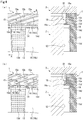
FIGS. 4A and 4B are partial side views and A-A sectional views of the seal ring according to the first embodiment for schematically illustrating a fluid film formation process in accordance with stages. -
FIG. 5 is a partial side view and an A-A sectional view of the seal ring according to the first embodiment for schematically illustrating, followingFIGS. 4A and 4B , the fluid film formation process in accordance with stages. -
FIG. 6 is a partial side view of a seal ring according to a second embodiment of the present invention. -
FIG. 7 is a B-B sectional view of the seal ring ofFIG. 6 . -
FIG. 8 is a partial side view of a seal ring according to a third embodiment of the present invention. -
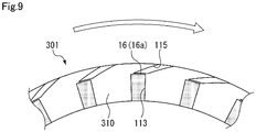
FIG. 9 is a partial side view of a seal ring according to a fourth embodiment of the present invention. -
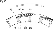
FIG. 10 is a partial side view of a seal ring according to a fifth embodiment of the present invention. - Hereinafter, modes for carrying out a seal ring according to the present invention will be described based on embodiments.
- A seal ring according to a first embodiment will be described with reference to
FIGS. 1 to 5 . Hereinafter, the right side in the plane of paper ofFIG. 2 will be described as a sealed fluid side L, and the left side in the plane of paper will be described as an atmosphere side A. Note that the fluid pressure of sealed fluid on the sealed fluid side L will be described as a higher pressure than an atmospheric pressure. Moreover, a sliding surface includes a flat surface and a groove recessed as compared to the flat surface. For the sake of convenience in description, the flat surface forming the sliding surface is, in the side views, indicated by the color of white, and the groove forming the sliding surface is indicated by dots. - The
seal ring 1 according to the present embodiment seals a portion between arotary shaft 2 and ahousing 3 of a rotary machine, therotary shaft 2 and thehousing 3 rotating relative to each other. In this manner, theseal ring 1 partitions the inside of thehousing 3 into the sealed fluid side L and the atmosphere side A (seeFIG. 2 ), and prevents leakage of the sealed fluid from the sealed fluid side L to the atmosphere side A. Note that therotary shaft 2 and thehousing 3 are made of a metal material such as stainless steel. Moreover, the sealed fluid is one used for the purpose of cooling and lubricating, e.g., a not-shown gear and a not-shown bearing provided in a machine chamber of the rotary machine, such as oil. - As illustrated in
FIGS. 1 to 3 , theseal ring 1 is a component molded with resin such as PTFE, and is provided with ajoint portion 1a at one spot in a circumferential direction to form a C-shape. Theseal ring 1 is used with theseal ring 1 being attached to anannular groove 20, theannular groove 20 being provided along the outer periphery of therotary shaft 2 and having a rectangular sectional shape. Therotary shaft 2 rotates clockwise as indicated by a white arrow inFIG. 3 , and theseal ring 1 rotates counterclockwise relative to theannular groove 20 of therotary shaft 2. Note that inFIG. 2 , the section of theseal ring 1 along a radial direction is schematically illustrated. - Moreover, the
seal ring 1 has a rectangular sectional shape. Theseal ring 1 is pressed to the atmosphere side A by the fluid pressure of the sealed fluid acting on a side surface on the sealed fluid side L, and accordingly, a sliding surface S1 formed on a side surface 10 (hereinafter sometimes merely referred to as a "side surface 10") side on the atmosphere side A slidably closely contacts a sliding surface S2 on a side wall surface 21 (hereinafter sometimes merely referred to as a "side wall surface 21") side of theannular groove 20 on the atmosphere side A. Further, in response to stress in an expansion direction due to the fluid pressure of the sealed fluid acting on an inner circumferential surface, theseal ring 1 is pressed in a radially outward direction, and accordingly, an outercircumferential surface 11 closely contacts an innercircumferential surface 31 of ashaft hole 30 of thehousing 3. - Note that the sliding surfaces S1, S2 form a substantial sliding region between the
side surface 10 of theseal ring 1 and theside wall surface 21 of theannular groove 20 of therotary shaft 2. Moreover, a non-sliding surface S1' is formed continuously to an outer diameter side of the sliding surface S1 on theside surface 10 side, and a non-sliding surface S2' is formed continuously to an inner diameter side of the sliding surface S2 on theside wall surface 21 side (seeFIG. 2 ) . - As illustrated in
FIGS. 1 to 4 , the sliding surface S1 formed on theside surface 10 side of theseal ring 1 includes aflat surface 16,multiple supply grooves 13 extending in the radial direction from an inner-diameter-side end portion of theside surface 10, acommunication groove 14 communicated with outer-diameter-side end portions of thesupply grooves 13 and formed continuously in a substantially annular shape across thejoint portion 1a, and multipleinclined grooves 15 formed inclined to the direction of rotation of therotary shaft 2 from the vicinity of an outer-diameter-side end portion of the communication groove 14 (i.e., an outer-diameter-side end portion of a later-describedseal portion 16a) and communicated with an outer-diameter-side end portion of the side surface 10 (on the atmosphere side A). Note that thesupply grooves 13 are arranged at equal intervals in the circumferential direction of the sliding surface S1, except for the vicinity of thejoint portion 1a. Moreover, theinclined grooves 15 extend from the sliding surface S1 to the non-sliding surface S1', and are arranged at equal intervals in the circumferential direction, except for the vicinity of thejoint portion 1a. - The
flat surface 16 includes theseal portion 16a positioned between the outer-diameter-side end portion of thecommunication groove 14 and an inner-diameter-side end portion of each of the multipleinclined grooves 15 and formed continuously in a substantially annular shape across thejoint portion 1a, an inner-diameter-side lubrication portion 16b sandwiched by adjacent ones of thesupply grooves 13 in the circumferential direction, and an outer-diameter-side lubrication portion 16c sandwiched by adjacent ones of theinclined grooves 15 in the circumferential direction (seeFIG. 3 ). The dimension of theseal portion 16a in the radial direction is 1/20 (preferably 1/5 to 1/50) of the dimension of the sliding surface S1 in the radial direction, and is the substantially same dimension as the dimension of the outer-diameter-side lubrication portion 16c in the circumferential direction. Note that the dimension of theseal portion 16a in the radial direction is preferably short, considering that the sealed fluid easily moves over theseal portion 16a. - As illustrated in
FIGS. 2 to 5 , thesupply groove 13 supplies, regardless of rotation/stop of therotary shaft 2, the sealed fluid to a portion between the sliding surfaces S1, S2 when the sealed fluid has a higher pressure than that of atmospheric air. Thesupply groove 13 has a rectangular shape as viewed from the side. Thesupply groove 13 opens on the inner diameter side (i.e., the sealed fluid side) of the sliding surface S1, and is communicated with thecommunication groove 14 on the outer diameter side. Moreover, abottom surface 13d (seeFIG. 4A ) of thesupply groove 13 is formed flat, and is parallel with theflat surface 16. The depth of thesupply groove 13 is several tens to several hundreds of µm and preferably 100 to 200 µm. Note that the depth of thesupply groove 13 may be much deeper (e.g., up to about a depth of 1 mm). - The
communication groove 14 is formed to extend in the circumferential direction at a position on the outer diameter side with respect to the center of the sliding surface S1 in the radial direction, has an arc shape as viewed from the side, and has a shorter dimension in the radial direction than the dimension of thesupply groove 13 in the circumferential direction. Moreover, abottom surface 14d of thecommunication groove 14 is formed flat, is parallel with theflat surface 16, and is formed continuously to thebottom surface 13d of thesupply groove 13. The depth of thecommunication groove 14 is substantially the same as that of the supply groove 13 (seeFIG. 4A ). - As illustrated in
FIGS. 2 to 5 , theinclined groove 15 extends to the outer diameter side in the rotation direction of therotary shaft 2 from theseal portion 16a, i.e., extends inclined with respect to the radial direction, and has the function of generating a drawing pressure in theinclined grooves 15 due to a flow in the radially outward direction upon rotation of therotary shaft 2. Theinclined groove 15 is configured such that aclosed portion 15d extending along the outer-diameter-side end portion of theseal portion 16a, a planar outerinclined wall portion 15b positioned on an opposite rotation side of therotary shaft 2 and formed perpendicularly to abottom surface 15e, a planar innerinclined wall portion 15c positioned on a rotation side of therotary shaft 2 and formed perpendicularly to thebottom surface 15e, and anopening 15a crossing the outerinclined wall portion 15b and the innerinclined wall portion 15c and communicated with a non-sliding surface S1' side (i.e., the atmosphere side A) form a parallelogram shape as viewed from the side. Theinclined groove 15 has the substantially same dimension in the circumferential direction as the dimension of thecommunication groove 14 in the radial direction, and has a longer dimension in an extension direction than the dimension in the circumferential direction. Moreover, thebottom surface 15e of theinclined groove 15 is formed flat, and is parallel with theflat surface 16. The depth of theinclined groove 15 is shallower than those of thesupply groove 13 and thecommunication groove 14. - Further, the outer-diameter-
side lubrication portion 16c having a shorter dimension in the circumferential direction than the dimension of theinclined groove 15 in the circumferential direction is interposed between adjacent ones of theinclined grooves 15 in the circumferential direction. Note that the dimensions of these portions may be the same as each other, or the outer-diameter-side lubrication portion 16c may have a longer dimension. Moreover, the multipleinclined grooves 15 may be formed with a curvature such that the outer-diameter-side lubrication portions 16c are formed to the outer diameter side with the substantially equal width. - Next, fluid film formation between the sliding surface S1 of the
seal ring 1 and the sliding surface S2 of theside wall surface 21 of the annular groove 20 (hereinafter sometimes merely referred to as "between the sliding surfaces S1, S2") will be described with reference toFIGS. 4A, 4B , and5 . Note that a case where therotary shaft 2 rotates clockwise as indicated by the white arrow inFIG. 3 , i.e., a case where theseal ring 1 rotates counterclockwise relative to theannular groove 20 of therotary shaft 2 inFIG. 3 , will be described herein by way of example. Further, note that each ofFIGS. 4A, 4B , and5 schematically illustrates an association between an enlarged partial side view of theseal ring 1 as viewed from the side and an A-A sectional view cut along thesupply groove 13, thecommunication groove 14, and theinclined groove 15 of the enlarged partial side view. - First, as illustrated in
FIG. 4A , when therotary shaft 2 stands still, thesupply grooves 13 and thecommunication groove 14 are filled with the sealed fluid due to the fluid pressure. Moreover, the high-pressure sealed fluid is supplied to thesupply grooves 13 and thecommunication groove 14, and due to a resting pressure, the force of separating the sliding surfaces S1, S2 acts on thesupply grooves 13 and thecommunication groove 14. - Next, as illustrated in
FIG. 4B , upon rotation of therotary shaft 2, the sliding surface S1 on theside surface 10 side slides on the sliding surface S2 on the side wall surface 21 (seeFIG. 2 ) side. Accordingly, the sealed fluid in thecommunication groove 14 generates a clockwise flow along thecommunication groove 14. Moreover, although not shown in the figure, the sliding surface S2 passes over thesupply grooves 13, and therefore, the sealed fluid flows out of thesupply grooves 13 to follow the rotation direction of therotary shaft 2. - Meanwhile, on the outer diameter side with respect to the
seal portion 16a, the sealed fluid and air in theinclined grooves 15 move from aclosed portion 15d side to anopening 15a side of theinclined groove 15, and accordingly, the drawing pressure is generated from theclosed portion 15d side to theopening 15a side of theinclined groove 15. Thus, a negative pressure is generated on theclosed portion 15d side. - The sealed fluid forming a fluid film on the
seal portion 16a is drawn into theinclined grooves 15 by such a negative pressure. Accordingly, the sealed fluid in thecommunication groove 14 leaks out to aseal portion 16a side, and the flow F of moving the sealed fluid over theseal portion 16a from thecommunication groove 14 and drawing the sealed fluid into theinclined grooves 15 is formed (seeFIG. 5 ). The fluid film is reliably formed on theseal portion 16a, and lubricity is enhanced. The fluid film of the sealed fluid is formed between the sliding surfaces S1, S2 due to, e.g., the flow F and the resting pressure, and the lubricity is enhanced. - Moreover, the multiple
inclined grooves 15 are formed at equal intervals across the circumferential direction, and therefore, a dynamic pressure is substantially uniformly generated across the outer diameter side of the sliding surface S1 (i.e., theseal portion 16a). Thus, stable buoyancy can be obtained across the circumferential direction. - Further, as described above, not only the sealed fluid is mainly supplied from the
communication groove 14 to a portion between the sliding surface S2 and theseal portion 16a, but also the high-pressure sealed fluid is supplied from theinclined grooves 15 and thecommunication groove 14 to the outer-diameter-side lubrication portion 16c interposed between adjacent ones of theinclined grooves 15 in the circumferential direction and is supplied from the inner diameter side of the sliding surface S1 and thesupply grooves 13 to the inner-diameter-side lubrication portion 16b defined by adjacent ones of thesupply grooves 13 and thecommunication groove 14. Thus, the fluid film of the sealed fluid having a substantially equal thickness is formed between the sliding surfaces S1, S2. - As described above, the high-pressure sealed fluid introduced through inner-diameter-side openings of the
supply grooves 13 moves over theseal portion 16a, and on the outer diameter side, is drawn by the drawing pressure due to the flow in the radially outward direction in theinclined grooves 15 upon rotation of therotary shaft 2. Accordingly, the flow F of sealed fluid in the radially outward direction is formed among thesupply grooves 13, thecommunication groove 14, and theinclined grooves 15. Thus, the fluid film can be formed with favorable balance in the circumferential direction among thesupply grooves 13, thecommunication groove 14, and theinclined grooves 15, and therefore, stable lubrication performance can be provided across a wide range of rotation speed. - Moreover, the sealed fluid is sufficiently supplied as described above, and therefore, the fluid film can be reliably formed between the sliding surfaces S1, S2 across a wide range of rotation speed. Thus, the lubricity of the
seal ring 1 can be enhanced. - Further, the
supply grooves 13, thecommunication groove 14, and theinclined grooves 15 among which the flow of sealed fluid in the radial direction is formed are separated in the radial direction by theseal portion 16a, and therefore, the fluid film is formed with favorable balance in the circumferential direction on theseal portion 16a. With this configuration, the lubricity of theseal portion 16a can be enhanced. - In addition, the
multiple supply grooves 13 are equally arranged in the circumferential direction, and therefore, the flow of sealed fluid in the radial direction is formed with favorable balance in the circumferential direction on theseal portion 16a. - Moreover, the
multiple supply grooves 13 are, on the inner diameter side of theseal portion 16a, communicated with each other through thecommunication groove 14 extending in the circumferential direction, and therefore, the high-pressure sealed fluid introduced through the inner-diameter-side openings of thesupply grooves 13 is supplied in the circumferential direction by thecommunication groove 14. Thus, the flow of sealed fluid in the radial direction is reliably formed with favorable balance in the circumferential direction on theseal portion 16a. - Further, the
seal ring 1 is in the C-shape, and therefore, seal performance can be stably maintained even when the circumferential length of theseal ring 1 changes due to thermal expansion/contraction. - Next, a seal ring according to a second embodiment will be described with reference to
FIGS. 6 and7 . Note that the same reference numerals are used to represent the same components as those described in the above-described embodiment, and overlapping description thereof will be omitted. - The
seal ring 101 in the second embodiment will be described. As illustrated inFIG. 6 , in the present embodiment, a sliding surface S1 (seeFIG. 2 ) formed at aside surface 110 of theseal ring 101 includes aflat surface 16,multiple supply grooves 13, acommunication groove 14, multipleinclined grooves 15, and adynamic pressure groove 12 provided between adjacent ones of thesupply grooves 13 in a circumferential direction. - The
dynamic pressure groove 12 has the function of generating a dynamic pressure according to rotation of arotary shaft 2. Thedynamic pressure groove 12 includes adeep groove 120 opening on an inner diameter side (i.e., the sealed fluid side) of theseal ring 101 and provided at the center in the circumferential direction and a pair ofshallow grooves 121, 122 (i.e., positive pressure generators and negative pressure generators) formed continuously from both sides of thedeep groove 120 in the circumferential direction and extending in the circumferential direction. An inner-diameter-side lubrication portion 16b in an inverted U-shape as viewed from the side is arranged between thedynamic pressure groove 12 and each of thesupply grooves 13 adjacent to such adynamic pressure groove 12 in the circumferential direction and thecommunication groove 14. Note that inFIGS. 6 and7 , the right side with respect to thedeep groove 120 in the plane of paper is the shallow groove 121 (i.e., the positive pressure generator), and the left side in the plane of paper is the shallow groove 122 (i.e., the negative pressure generator). - Specifically, as illustrated in
FIG. 7 , thedeep groove 120 has a bottom surface formed flat, and theshallow grooves shallow grooves deep groove 120 side to terminal ends in the circumferential direction. Moreover, the bottom surface of thedeep groove 120 is formed much deeper than deepest portions of theshallow grooves deep groove 120 is several tens to several hundreds of µm and preferably 100 to 200 µm. - According to such a configuration, in fluid film formation between the sliding surfaces S1, S2, a negative pressure is generated in each shallow groove 122 (hereinafter merely referred to as a "
shallow groove 122") of theseal ring 101 on a side (i.e., the left side in the plane of paper ofFIG. 6 ) opposite to a rotation direction of therotary shaft 2. Meanwhile, sealed fluid introduced into thedeep grooves 120 is supplied to each shallow groove 121 (hereinafter merely referred to as a "shallow groove 121") of theseal ring 101 on the same side (i.e., the right side in the plane of paper ofFIG. 6 ) as the rotation direction, and a positive pressure is generated in such ashallow groove 121 due to wedge action caused by the inclined surface. Then, the positive pressure is generated across the entirety of thedynamic pressure grooves 12, and accordingly, the force of slightly separating the sliding surfaces S1, S2 from each other, i.e., so-called buoyancy, is obtained. That is, the positive pressure (i.e., the buoyancy) can be generated not only on an outer diameter side of the sliding surfaces S1, S2 but also on an inner diameter side by thedynamic pressure grooves 12. Thus, responsiveness of fluid film formation to rotation of therotary shaft 2 can be enhanced. - Moreover, the force of sucking the sealed fluid present between the sliding surfaces S1, S2 around the
shallow groove 122 generating the negative pressure acts on such ashallow groove 122. Thus, the sealed fluid is supplied to theshallow groove 122 and a surrounding inner-diameter-side lubrication portion 16b thereof from thesupply groove 13 adjacent to such ashallow groove 122 in the circumferential direction. Further, theshallow groove 122 as the negative pressure generator in thedynamic pressure groove 12 opens on the inner diameter side (i.e., the sealed fluid side), and the sealed fluid is also introduced from the inner diameter side of the sliding surface S1. Thus, the sealed fluid is easily held on theshallow groove 122. - Further, the negative pressure generated by the
inclined grooves 15 can be partially cancelled by the positive pressure generated on the outer diameter side of the sliding surface S1, and the sliding surfaces S1, S2 can be easily separated from each other by the dynamic pressure generated across the entirety of thedynamic pressure grooves 12. Thus, the flow of sealed fluid in a radial direction is easily formed on aseal portion 16a. - In addition, the
dynamic pressure groove 12 arranged on the inner diameter side of the sliding surface S1 may be freely formed, and may be formed as, e.g., a T-shaped groove, a Rayleigh step, or a spiral groove. - Next, a seal ring according to a third embodiment will be described with reference to
FIG. 8 . Note that the same reference numerals are used to represent the same components as those described in the above-described embodiments, and overlapping description thereof will be omitted. - The
seal ring 201 in the third embodiment will be described. As illustrated inFIG. 8 , in the present embodiment, a sliding surface S1 (seeFIG. 2 ) formed at aside surface 210 of theseal ring 201 includes aflat surface 16,multiple supply grooves 13, acommunication groove 14, multipleinclined grooves 15, and adynamic pressure groove 112 provided between adjacent ones of thesupply grooves 13 in a circumferential direction. - The
dynamic pressure groove 112 includes adeep groove 220 opening on an inner diameter side (i.e., the sealed fluid side) of theseal ring 201, provided at the center in the circumferential direction, and communicated with the communication groove at an outer-diameter-side end portion and a pair ofshallow grooves deep groove 220 in the circumferential direction and extending in the circumferential direction. An inner-diameter-side lubrication portion 16b in an L-shape as viewed from the side is arranged between thedynamic pressure groove 112 and each of thesupply grooves 13 adjacent to such adynamic pressure groove 112 and thecommunication groove 14. - According to such a configuration, in fluid film formation between the sliding surfaces S1, S2, sealed fluid can be supplied to the
communication groove 14 not only from thesupply grooves 13 but also from thedeep grooves 220 of thedynamic pressure grooves 112. Thus, a fluid film can be more reliably formed between the sliding surfaces S1, S2 across a wide range of rotation speed, and lubricity of theseal ring 201 can be enhanced. - Next, a seal ring according to a fourth embodiment will be described with reference to
FIG. 9 . Note that the same reference numerals are used to represent the same components as those described in the above-described embodiments, and overlapping description thereof will be omitted. - The
seal ring 301 in the fourth embodiment will be described. As illustrated inFIG. 9 , in the present embodiment, a sliding surface S1 (seeFIG. 2 ) formed at aside surface 310 of theseal ring 301 includes aflat surface 16,multiple supply grooves 113, and a singleinclined groove 115 inclined to a rotation direction of arotary shaft 2 from the vicinity of an outer-diameter-side end portion of each supply groove 113 (e.g., an outer-diameter-side end portion of aseal portion 16a) to an outer-diameter-side end portion of theside surface 310. According to such a configuration, a flow F (seeFIG. 5 ) moving over theseal portion 16a at outermost diameter portions of the sliding surfaces S1, S2 can be formed with a simple configuration. - Next, a seal ring according to a fifth embodiment will be described with reference to
FIG. 10 . Note that the same reference numerals are used to represent the same components as those described in the above-described embodiments, and overlapping description thereof will be omitted. - The
seal ring 401 in the fifth embodiment will be described. As illustrated inFIG. 10 , in the present embodiment, a sliding surface S1 (seeFIG. 2 ) formed at aside surface 410 of theseal ring 401 includes aflat surface 16,multiple supply grooves 213,multiple communication paths 214 each communicated with adjacent two of thesupply grooves 213, and multipleinclined grooves 215 inclined to a relative turning direction from the vicinity of an outer-diameter-side end portion of each communication path 214 (e.g., an outer-diameter-side end portion of theseal portion 16a) to an outer-diameter-side end portion of theside surface 410. According to such a configuration, a flow F (seeFIG. 5 ) moving over theseal portion 16a at outermost diameter portions of the sliding surfaces S1, S2 can be formed with a simpler configuration than those of the first to third embodiments. - The embodiments of the present invention have been described above with reference to the drawings, but specific configurations are not limited to these embodiments. The present invention also includes even changes and additions made without departing from the scope of the present invention.
- For example, the configuration of the dynamic pressure groove of the second embodiment or the third embodiment may be applied to the fourth and fifth embodiments.
- Moreover, the form in which the
rotary shaft 2 is turned clockwise to generate the dynamic pressure in theinclined grooves 15 has been described. However, therotary shaft 2 is rotated counterclockwise to move the sealed fluid from theopening 15a side to theclosed portion 15d side of theinclined groove 15, and therefore, outflow of the sealed fluid can be reduced with favorable responsiveness. - Further, the number and shape of dynamic pressure grooves, supply grooves, communication paths, or inclined grooves provided at the sliding surface S1 or the non-sliding surface S1' of the seal ring may be changed as necessary such that a desired dynamic pressure effect is obtained. Note that the location and shape of the deep groove of the dynamic pressure groove to which the sealed fluid is introduced, the location and shape of the supply groove to which the sealed fluid is introduced, the location and shape of the communication path to which the sealed fluid is introduced, and the location and shape of the inclined groove to which the sealed fluid is introduced may be changed as necessary according to the assumed degree of abrasion of the sliding surface.
- In addition, the inclined groove may have a bottom surface as an inclined surface formed such that the inclined groove gradually becomes shallower from the opening side to the closed portion. With such a form, the drawing pressure is more easily generated due to taper action.
- Moreover, the seal ring may be formed in an annular shape without the
joint portion 1a, and the outer shape thereof is not limited to a circular shape as viewed from the side. The seal ring may be formed in a polygonal shape. - Further, the seal ring is not limited to the rectangular sectional shape, and for example, may have a trapezoidal sectional shape or a polygonal sectional shape. The seal ring may be configured such that the side surface forming the sliding surface S1 is inclined.
- In addition, the grooves described in the above-described embodiments may be formed at the sliding surface S2 of the
annular groove 20 of therotary shaft 2. - Moreover, the oil has been described as the example of the sealed fluid, but the sealed fluid may be liquid such as water or coolant or gas such as air or nitrogen.
-
- 1 to 401
- Seal ring
- 2
- Rotary shaft
- 3
- Housing
- 10
- Side surface
- 12
- Dynamic pressure groove
- 13
- Supply groove
- 14
- Communication groove
- 15
- Inclined groove
- 16
- Flat surface
- 16a
- Seal portion
- 16b
- Inner-diameter-side lubrication portion
- 16c
- Outer-diameter-side lubrication portion
- 20
- Annular groove
- 21
- Side wall surface
- 110
- Side surface
- 112
- Dynamic pressure groove
- 113
- Supply groove
- 214
- Communication path
- 115
- Inclined groove
- 210
- Side surface
- 213
- Supply groove
- 215
- Inclined groove
- 310
- Side surface
- 410
- Side surface
- S1, S2
- Sliding surface
- S1', S2'
- Non-sliding surface
Claims (5)
- A seal ring for sealing a clearance between a rotary shaft and a housing, comprising:inclined grooves formed at a sliding surface so as to be arranged in a circumferential direction, the inclined grooves being open on an outer diameter side of the seal ring to generate a drawing pressure; andsupply grooves being open on a sealed fluid side of the seal ring and extending in a radially outward direction toward inner diameter sides of the inclined grooves.
- The seal ring according to claim 1, wherein
a seal portion is formed continuously in the circumferential direction and positioned between the supply grooves and the inclined grooves. - The seal ring according to claim 1 or 2, wherein
the supply grooves are equally arranged in the circumferential direction. - The seal ring according to any one of claims 1 to 3, wherein
the supply grooves are communicated with each other through a communication groove which is positioned on the inner diameter side of the seal portion and extends in the circumferential direction. - The seal ring according to any one of claims 1 to 4, further comprising
dynamic pressure grooves each formed at the sliding surface between adjacent two of the supply grooves in the circumferential direction and being open on the sealed fluid side of the seal ring.
Applications Claiming Priority (2)
| Application Number | Priority Date | Filing Date | Title |
|---|---|---|---|
| JP2018095699 | 2018-05-17 | ||
| PCT/JP2019/019501 WO2019221229A1 (en) | 2018-05-17 | 2019-05-16 | Seal ring |
Publications (4)
| Publication Number | Publication Date |
|---|---|
| EP3816489A1 true EP3816489A1 (en) | 2021-05-05 |
| EP3816489A4 EP3816489A4 (en) | 2022-03-02 |
| EP3816489C0 EP3816489C0 (en) | 2024-10-09 |
| EP3816489B1 EP3816489B1 (en) | 2024-10-09 |
Family
ID=68540383
Family Applications (1)
| Application Number | Title | Priority Date | Filing Date |
|---|---|---|---|
| EP19803913.3A Active EP3816489B1 (en) | 2018-05-17 | 2019-05-16 | Seal ring |
Country Status (5)
| Country | Link |
|---|---|
| US (1) | US11644100B2 (en) |
| EP (1) | EP3816489B1 (en) |
| JP (1) | JP7242659B2 (en) |
| CN (1) | CN112088268B (en) |
| WO (1) | WO2019221229A1 (en) |
Families Citing this family (16)
| Publication number | Priority date | Publication date | Assignee | Title |
|---|---|---|---|---|
| US11644100B2 (en) * | 2018-05-17 | 2023-05-09 | Eagle Industry Co., Ltd. | Seal ring |
| CN112105850A (en) * | 2018-05-17 | 2020-12-18 | 伊格尔工业股份有限公司 | Sealing ring |
| EP3816490B1 (en) * | 2018-05-17 | 2024-11-06 | Eagle Industry Co., Ltd. | Seal ring |
| EP3842673B1 (en) | 2018-08-24 | 2026-04-22 | Eagle Industry Co., Ltd. | Sliding member |
| EP3862600B1 (en) | 2018-10-01 | 2025-05-21 | Eagle Industry Co., Ltd. | Sliding member |
| CN112789434B (en) | 2018-10-24 | 2023-09-29 | 伊格尔工业股份有限公司 | sliding parts |
| EP3889474A4 (en) | 2018-11-30 | 2022-08-10 | Eagle Industry Co., Ltd. | Sliding component |
| KR102541901B1 (en) | 2018-12-21 | 2023-06-13 | 이구루코교 가부시기가이샤 | sliding parts |
| KR102610647B1 (en) | 2019-02-04 | 2023-12-07 | 이구루코교 가부시기가이샤 | sliding parts |
| CN117432709A (en) | 2019-02-14 | 2024-01-23 | 伊格尔工业股份有限公司 | sliding parts |
| JP7374573B2 (en) | 2019-02-21 | 2023-11-07 | イーグル工業株式会社 | sliding parts |
| JP7399966B2 (en) * | 2019-07-26 | 2023-12-18 | イーグル工業株式会社 | sliding parts |
| EP4306826A4 (en) | 2021-03-12 | 2025-03-26 | Eagle Industry Co., Ltd. | SLIDING ELEMENT |
| JP7520473B2 (en) * | 2021-04-28 | 2024-07-23 | イーグル工業株式会社 | Sliding parts |
| US12404936B2 (en) | 2021-09-28 | 2025-09-02 | Eagle Indusry Co., Ltd. | Sliding component |
| WO2023223914A1 (en) * | 2022-05-19 | 2023-11-23 | イーグル工業株式会社 | Sliding component |
Family Cites Families (70)
| Publication number | Priority date | Publication date | Assignee | Title |
|---|---|---|---|---|
| US3695789A (en) | 1970-04-13 | 1972-10-03 | Case Co J I | Balancing mechanism for fluid translating device |
| JPS5832099A (en) | 1981-08-21 | 1983-02-24 | Hitachi Metals Ltd | Preparation of single crystal |
| EP0218322A1 (en) | 1985-08-12 | 1987-04-15 | Ford Motor Company Limited | Transverse leaf spring suspension |
| CH677266A5 (en) | 1986-10-28 | 1991-04-30 | Pacific Wietz Gmbh & Co Kg | |
| US5368314A (en) | 1986-10-28 | 1994-11-29 | Pacific Wietz Gmbh & Co. Kg | Contactless pressurizing-gas shaft seal |
| US5246295A (en) | 1991-10-30 | 1993-09-21 | Ide Russell D | Non-contacting mechanical face seal of the gap-type |
| JPH0535249Y2 (en) | 1988-03-31 | 1993-09-07 | ||
| JP2554542B2 (en) | 1989-07-06 | 1996-11-13 | 株式会社 藤井合金製作所 | Gas cock manufacturing method |
| JPH0388062A (en) | 1989-08-31 | 1991-04-12 | Toshiba Corp | Device for preparing document |
| JPH07117165B2 (en) | 1991-02-27 | 1995-12-18 | 日本ピラー工業株式会社 | Non-contact type sealing device |
| DE4209484A1 (en) | 1991-06-12 | 1993-10-21 | Heinz Konrad Prof Dr I Mueller | Mechanical seal with return flow |
| US5174584A (en) | 1991-07-15 | 1992-12-29 | General Electric Company | Fluid bearing face seal for gas turbine engines |
| JPH0561566A (en) | 1991-09-03 | 1993-03-12 | Canon Inc | Laptop-type information processing device |
| US5169159A (en) | 1991-09-30 | 1992-12-08 | General Electric Company | Effective sealing device for engine flowpath |
| JP2560805Y2 (en) * | 1992-01-31 | 1998-01-26 | エヌティエヌ株式会社 | Seal ring |
| US5447316A (en) * | 1992-02-06 | 1995-09-05 | Eagle Industry Co., Ltd. | Gas seal |
| AU685502B2 (en) | 1993-09-01 | 1998-01-22 | Durametallic Corporation | Face seal with angled and annular grooves |
| US5498007A (en) * | 1994-02-01 | 1996-03-12 | Durametallic Corporation | Double gas barrier seal |
| JPH07242197A (en) | 1994-03-04 | 1995-09-19 | Nippon Marine Techno Kk | Stern tube sealing device |
| JPH0828709A (en) | 1994-07-22 | 1996-02-02 | Nok Corp | Seal ring |
| JPH09210211A (en) | 1996-02-01 | 1997-08-12 | Riken Corp | Seal ring |
| JPH10281299A (en) | 1997-04-11 | 1998-10-23 | Mitsubishi Heavy Ind Ltd | Mechanical seal device |
| JP3477570B2 (en) | 1997-06-02 | 2003-12-10 | 正喜 江刺 | Active conduit and method of manufacturing the same |
| JP4109374B2 (en) | 1999-02-23 | 2008-07-02 | バルチラジャパン株式会社 | Stern tube sealing device |
| US6189896B1 (en) | 1999-04-08 | 2001-02-20 | Caterpillar Inc. | Controlled leakage rotating seal ring with elements for receiving and holding a lubricant on a face thereof |
| JP4719414B2 (en) * | 2003-12-22 | 2011-07-06 | イーグル工業株式会社 | Sliding parts |
| US7377518B2 (en) * | 2004-05-28 | 2008-05-27 | John Crane Inc. | Mechanical seal ring assembly with hydrodynamic pumping mechanism |
| JP4820471B2 (en) | 2004-11-09 | 2011-11-24 | イーグル工業株式会社 | Mechanical seal device |
| JP4755428B2 (en) | 2005-02-25 | 2011-08-24 | バルチラジャパン株式会社 | Shaft seal device for marine propulsion shaft |
| AT503578B1 (en) | 2006-04-28 | 2007-11-15 | Andritz Ag Maschf | SEALING ARRANGEMENT |
| JP2008275052A (en) | 2007-04-27 | 2008-11-13 | Nok Corp | Seal ring |
| JP2009250378A (en) | 2008-04-08 | 2009-10-29 | Eagle Ind Co Ltd | Mechanical seal device for liquid |
| CN201448439U (en) | 2009-06-30 | 2010-05-05 | 张家港市金鹰密封件厂 | Friction ring for mechanical sealing arrangement |
| CN102483162A (en) * | 2010-02-26 | 2012-05-30 | Nok株式会社 | sealing ring |
| EP2549155B1 (en) | 2010-03-15 | 2016-08-10 | Eagle Industry Co., Ltd. | Sliding member |
| JP5122607B2 (en) | 2010-06-17 | 2013-01-16 | キヤノンマシナリー株式会社 | Flat sliding mechanism |
| CN103097782B (en) | 2010-10-06 | 2016-01-20 | 伊格尔工业股份有限公司 | Slide member |
| CN102619742B (en) | 2012-03-07 | 2016-04-20 | 大连华阳密封股份有限公司 | Dry gas seals for bi-directional rotary internal pressure pumps |
| EP2881632B1 (en) | 2012-08-04 | 2018-04-04 | Eagle Industry Co., Ltd. | Sliding component |
| JP2014055645A (en) * | 2012-09-13 | 2014-03-27 | Nok Corp | Seal ring |
| US9777840B2 (en) * | 2012-09-29 | 2017-10-03 | Eagle Industry Co., Ltd. | Sliding component |
| JP6219367B2 (en) | 2013-03-14 | 2017-10-25 | イーグルブルグマンジャパン株式会社 | Mechanical seal device |
| CN104919229B (en) | 2013-04-24 | 2017-05-31 | 伊格尔工业股份有限公司 | sliding parts |
| JP6386814B2 (en) | 2013-07-03 | 2018-09-05 | Ntn株式会社 | Seal ring |
| WO2015045974A1 (en) | 2013-09-27 | 2015-04-02 | 株式会社リケン | Seal ring |
| US9695940B2 (en) * | 2013-12-18 | 2017-07-04 | Kaydon Ring & Seal, Inc. | Bidirectional lift-off circumferential shaft seal segment and a shaft seal including a plurality of the segments |
| US10865883B2 (en) * | 2014-01-24 | 2020-12-15 | Nok Corporation | Sealing ring |
| EP3929455B1 (en) | 2014-12-22 | 2026-01-28 | Eagle Industry Co., Ltd. | Plain bearing and pump |
| JP6424949B2 (en) * | 2015-03-16 | 2018-11-21 | Nok株式会社 | Seal ring |
| EP3273117B1 (en) | 2015-03-16 | 2019-10-23 | Nok Corporation | Sealing ring |
| US10428948B2 (en) * | 2015-03-16 | 2019-10-01 | Nok Corporation | Seal ring |
| EP3284981B1 (en) * | 2015-04-15 | 2020-11-04 | Eagle Industry Co., Ltd. | Sliding parts |
| WO2016186019A1 (en) * | 2015-05-19 | 2016-11-24 | イーグル工業株式会社 | Sliding component |
| JP6186413B2 (en) * | 2015-10-15 | 2017-08-23 | 株式会社リケン | Seal ring |
| JP6798776B2 (en) | 2015-10-16 | 2020-12-09 | 株式会社リケン | Seal ring |
| WO2017122358A1 (en) | 2016-01-15 | 2017-07-20 | バルチラジャパン株式会社 | Stern tube sealing system, stern tube sealing device, ship, and stern tube sealing method |
| JP6937766B2 (en) * | 2016-10-14 | 2021-09-22 | イーグル工業株式会社 | Sliding parts |
| JP6910371B2 (en) * | 2016-11-14 | 2021-07-28 | イーグル工業株式会社 | Sliding parts |
| US11143232B2 (en) | 2016-11-16 | 2021-10-12 | Eagle Industry Co., Ltd. | Sliding component |
| KR102447226B1 (en) | 2016-12-07 | 2022-09-26 | 이구루코교 가부시기가이샤 | sliding parts |
| KR102377127B1 (en) | 2017-08-28 | 2022-03-23 | 이구루코교 가부시기가이샤 | sliding parts |
| WO2019049847A1 (en) | 2017-09-05 | 2019-03-14 | イーグル工業株式会社 | Sliding parts |
| CN111108312B (en) * | 2017-09-21 | 2022-05-10 | Nok株式会社 | seal ring |
| DE112019000742T5 (en) * | 2018-02-08 | 2020-10-15 | Nok Corporation | SEAL RING |
| WO2019221226A1 (en) | 2018-05-17 | 2019-11-21 | イーグル工業株式会社 | Seal ring |
| JP7214722B2 (en) | 2018-05-17 | 2023-01-30 | イーグル工業株式会社 | Seal ring |
| US11644100B2 (en) * | 2018-05-17 | 2023-05-09 | Eagle Industry Co., Ltd. | Seal ring |
| CN112105850A (en) | 2018-05-17 | 2020-12-18 | 伊格尔工业股份有限公司 | Sealing ring |
| JP7374573B2 (en) | 2019-02-21 | 2023-11-07 | イーグル工業株式会社 | sliding parts |
| JP7419346B2 (en) | 2019-03-22 | 2024-01-22 | イーグル工業株式会社 | sliding parts |
-
2019
- 2019-05-16 US US17/047,645 patent/US11644100B2/en active Active
- 2019-05-16 CN CN201980027774.4A patent/CN112088268B/en active Active
- 2019-05-16 WO PCT/JP2019/019501 patent/WO2019221229A1/en not_active Ceased
- 2019-05-16 JP JP2020519917A patent/JP7242659B2/en active Active
- 2019-05-16 EP EP19803913.3A patent/EP3816489B1/en active Active
Also Published As
| Publication number | Publication date |
|---|---|
| JP7242659B2 (en) | 2023-03-20 |
| EP3816489C0 (en) | 2024-10-09 |
| CN112088268B (en) | 2023-06-23 |
| CN112088268A (en) | 2020-12-15 |
| EP3816489B1 (en) | 2024-10-09 |
| US20210116029A1 (en) | 2021-04-22 |
| WO2019221229A1 (en) | 2019-11-21 |
| US11644100B2 (en) | 2023-05-09 |
| EP3816489A4 (en) | 2022-03-02 |
| JPWO2019221229A1 (en) | 2021-05-27 |
Similar Documents
| Publication | Publication Date | Title |
|---|---|---|
| EP3816487B1 (en) | Seal ring | |
| EP3816489B1 (en) | Seal ring | |
| EP3816488B1 (en) | Seal ring | |
| US11530749B2 (en) | Seal ring | |
| EP3795868B1 (en) | Seal ring | |
| US11767916B2 (en) | Sliding components | |
| JP6861730B2 (en) | Sliding parts | |
| US10655736B2 (en) | Sliding component | |
| EP4332415A1 (en) | Sliding component |
Legal Events
| Date | Code | Title | Description |
|---|---|---|---|
| STAA | Information on the status of an ep patent application or granted ep patent |
Free format text: STATUS: THE INTERNATIONAL PUBLICATION HAS BEEN MADE |
|
| PUAI | Public reference made under article 153(3) epc to a published international application that has entered the european phase |
Free format text: ORIGINAL CODE: 0009012 |
|
| STAA | Information on the status of an ep patent application or granted ep patent |
Free format text: STATUS: REQUEST FOR EXAMINATION WAS MADE |
|
| 17P | Request for examination filed |
Effective date: 20201201 |
|
| AK | Designated contracting states |
Kind code of ref document: A1 Designated state(s): AL AT BE BG CH CY CZ DE DK EE ES FI FR GB GR HR HU IE IS IT LI LT LU LV MC MK MT NL NO PL PT RO RS SE SI SK SM TR |
|
| DAV | Request for validation of the european patent (deleted) | ||
| DAX | Request for extension of the european patent (deleted) | ||
| A4 | Supplementary search report drawn up and despatched |
Effective date: 20220128 |
|
| RIC1 | Information provided on ipc code assigned before grant |
Ipc: F16J 15/34 20060101ALI20220124BHEP Ipc: F16J 15/44 20060101ALI20220124BHEP Ipc: F16J 15/16 20060101ALI20220124BHEP Ipc: F16J 15/3272 20160101ALI20220124BHEP Ipc: F16J 15/324 20160101ALI20220124BHEP Ipc: F16J 15/18 20060101AFI20220124BHEP |
|
| STAA | Information on the status of an ep patent application or granted ep patent |
Free format text: STATUS: EXAMINATION IS IN PROGRESS |
|
| 17Q | First examination report despatched |
Effective date: 20230418 |
|
| GRAP | Despatch of communication of intention to grant a patent |
Free format text: ORIGINAL CODE: EPIDOSNIGR1 |
|
| STAA | Information on the status of an ep patent application or granted ep patent |
Free format text: STATUS: GRANT OF PATENT IS INTENDED |
|
| INTG | Intention to grant announced |
Effective date: 20240522 |
|
| GRAS | Grant fee paid |
Free format text: ORIGINAL CODE: EPIDOSNIGR3 |
|
| GRAA | (expected) grant |
Free format text: ORIGINAL CODE: 0009210 |
|
| STAA | Information on the status of an ep patent application or granted ep patent |
Free format text: STATUS: THE PATENT HAS BEEN GRANTED |
|
| AK | Designated contracting states |
Kind code of ref document: B1 Designated state(s): AL AT BE BG CH CY CZ DE DK EE ES FI FR GB GR HR HU IE IS IT LI LT LU LV MC MK MT NL NO PL PT RO RS SE SI SK SM TR |
|
| REG | Reference to a national code |
Ref country code: CH Ref legal event code: EP |
|
| REG | Reference to a national code |
Ref country code: DE Ref legal event code: R096 Ref document number: 602019060161 Country of ref document: DE |
|
| REG | Reference to a national code |
Ref country code: IE Ref legal event code: FG4D |
|
| U01 | Request for unitary effect filed |
Effective date: 20241009 |
|
| U07 | Unitary effect registered |
Designated state(s): AT BE BG DE DK EE FI FR IT LT LU LV MT NL PT RO SE SI Effective date: 20241024 |
|
| PG25 | Lapsed in a contracting state [announced via postgrant information from national office to epo] |
Ref country code: IS Free format text: LAPSE BECAUSE OF FAILURE TO SUBMIT A TRANSLATION OF THE DESCRIPTION OR TO PAY THE FEE WITHIN THE PRESCRIBED TIME-LIMIT Effective date: 20250209 Ref country code: HR Free format text: LAPSE BECAUSE OF FAILURE TO SUBMIT A TRANSLATION OF THE DESCRIPTION OR TO PAY THE FEE WITHIN THE PRESCRIBED TIME-LIMIT Effective date: 20241009 |
|
| PG25 | Lapsed in a contracting state [announced via postgrant information from national office to epo] |
Ref country code: ES Free format text: LAPSE BECAUSE OF FAILURE TO SUBMIT A TRANSLATION OF THE DESCRIPTION OR TO PAY THE FEE WITHIN THE PRESCRIBED TIME-LIMIT Effective date: 20241009 |
|
| PG25 | Lapsed in a contracting state [announced via postgrant information from national office to epo] |
Ref country code: NO Free format text: LAPSE BECAUSE OF FAILURE TO SUBMIT A TRANSLATION OF THE DESCRIPTION OR TO PAY THE FEE WITHIN THE PRESCRIBED TIME-LIMIT Effective date: 20250109 |
|
| PG25 | Lapsed in a contracting state [announced via postgrant information from national office to epo] |
Ref country code: GR Free format text: LAPSE BECAUSE OF FAILURE TO SUBMIT A TRANSLATION OF THE DESCRIPTION OR TO PAY THE FEE WITHIN THE PRESCRIBED TIME-LIMIT Effective date: 20250110 |
|
| PG25 | Lapsed in a contracting state [announced via postgrant information from national office to epo] |
Ref country code: PL Free format text: LAPSE BECAUSE OF FAILURE TO SUBMIT A TRANSLATION OF THE DESCRIPTION OR TO PAY THE FEE WITHIN THE PRESCRIBED TIME-LIMIT Effective date: 20241009 |
|
| PG25 | Lapsed in a contracting state [announced via postgrant information from national office to epo] |
Ref country code: RS Free format text: LAPSE BECAUSE OF FAILURE TO SUBMIT A TRANSLATION OF THE DESCRIPTION OR TO PAY THE FEE WITHIN THE PRESCRIBED TIME-LIMIT Effective date: 20250109 |
|
| U20 | Renewal fee for the european patent with unitary effect paid |
Year of fee payment: 7 Effective date: 20250519 |
|
| PG25 | Lapsed in a contracting state [announced via postgrant information from national office to epo] |
Ref country code: SM Free format text: LAPSE BECAUSE OF FAILURE TO SUBMIT A TRANSLATION OF THE DESCRIPTION OR TO PAY THE FEE WITHIN THE PRESCRIBED TIME-LIMIT Effective date: 20241009 |
|
| PG25 | Lapsed in a contracting state [announced via postgrant information from national office to epo] |
Ref country code: SK Free format text: LAPSE BECAUSE OF FAILURE TO SUBMIT A TRANSLATION OF THE DESCRIPTION OR TO PAY THE FEE WITHIN THE PRESCRIBED TIME-LIMIT Effective date: 20241009 |
|
| PG25 | Lapsed in a contracting state [announced via postgrant information from national office to epo] |
Ref country code: CZ Free format text: LAPSE BECAUSE OF FAILURE TO SUBMIT A TRANSLATION OF THE DESCRIPTION OR TO PAY THE FEE WITHIN THE PRESCRIBED TIME-LIMIT Effective date: 20241009 |
|
| PLBE | No opposition filed within time limit |
Free format text: ORIGINAL CODE: 0009261 |
|
| STAA | Information on the status of an ep patent application or granted ep patent |
Free format text: STATUS: NO OPPOSITION FILED WITHIN TIME LIMIT |
|
| 26N | No opposition filed |
Effective date: 20250710 |
|
| REG | Reference to a national code |
Ref country code: CH Ref legal event code: H13 Free format text: ST27 STATUS EVENT CODE: U-0-0-H10-H13 (AS PROVIDED BY THE NATIONAL OFFICE) Effective date: 20251223 |
|
| PG25 | Lapsed in a contracting state [announced via postgrant information from national office to epo] |
Ref country code: CH Free format text: LAPSE BECAUSE OF NON-PAYMENT OF DUE FEES Effective date: 20250531 |
|
| PG25 | Lapsed in a contracting state [announced via postgrant information from national office to epo] |
Ref country code: MC Free format text: LAPSE BECAUSE OF FAILURE TO SUBMIT A TRANSLATION OF THE DESCRIPTION OR TO PAY THE FEE WITHIN THE PRESCRIBED TIME-LIMIT Effective date: 20241009 |
|
| PGFP | Annual fee paid to national office [announced via postgrant information from national office to epo] |
Ref country code: GB Payment date: 20260323 Year of fee payment: 8 |
|
| PG25 | Lapsed in a contracting state [announced via postgrant information from national office to epo] |
Ref country code: IE Free format text: LAPSE BECAUSE OF NON-PAYMENT OF DUE FEES Effective date: 20250516 |