EP3816376A1 - State determination device for door lock device, state determination method for door lock device, and state determination program for door lock device - Google Patents
State determination device for door lock device, state determination method for door lock device, and state determination program for door lock device Download PDFInfo
- Publication number
- EP3816376A1 EP3816376A1 EP20202278.6A EP20202278A EP3816376A1 EP 3816376 A1 EP3816376 A1 EP 3816376A1 EP 20202278 A EP20202278 A EP 20202278A EP 3816376 A1 EP3816376 A1 EP 3816376A1
- Authority
- EP
- European Patent Office
- Prior art keywords
- door lock
- lock device
- door
- time
- state determination
- Prior art date
- Legal status (The legal status is an assumption and is not a legal conclusion. Google has not performed a legal analysis and makes no representation as to the accuracy of the status listed.)
- Granted
Links
Images


Classifications
-
- E—FIXED CONSTRUCTIONS
- E05—LOCKS; KEYS; WINDOW OR DOOR FITTINGS; SAFES
- E05B—LOCKS; ACCESSORIES THEREFOR; HANDCUFFS
- E05B81/00—Power-actuated vehicle locks
- E05B81/54—Electrical circuits
- E05B81/56—Control of actuators
- E05B81/58—Control of actuators including time control, e.g. for controlling run-time of electric motors
-
- E—FIXED CONSTRUCTIONS
- E05—LOCKS; KEYS; WINDOW OR DOOR FITTINGS; SAFES
- E05B—LOCKS; ACCESSORIES THEREFOR; HANDCUFFS
- E05B83/00—Vehicle locks specially adapted for particular types of wing or vehicle
- E05B83/36—Locks for passenger or like doors
- E05B83/363—Locks for passenger or like doors for railway vehicles
-
- B—PERFORMING OPERATIONS; TRANSPORTING
- B61—RAILWAYS
- B61D—BODY DETAILS OR KINDS OF RAILWAY VEHICLES
- B61D19/00—Door arrangements specially adapted for rail vehicles
- B61D19/02—Door arrangements specially adapted for rail vehicles for carriages
-
- B—PERFORMING OPERATIONS; TRANSPORTING
- B61—RAILWAYS
- B61L—GUIDING RAILWAY TRAFFIC; ENSURING THE SAFETY OF RAILWAY TRAFFIC
- B61L15/00—Indicators provided on the vehicle or train for signalling purposes
- B61L15/0081—On-board diagnosis or maintenance
-
- E—FIXED CONSTRUCTIONS
- E05—LOCKS; KEYS; WINDOW OR DOOR FITTINGS; SAFES
- E05B—LOCKS; ACCESSORIES THEREFOR; HANDCUFFS
- E05B81/00—Power-actuated vehicle locks
- E05B81/54—Electrical circuits
- E05B81/64—Monitoring or sensing, e.g. by using switches or sensors
- E05B81/72—Monitoring or sensing, e.g. by using switches or sensors the lock status, i.e. locked or unlocked condition
-
- G—PHYSICS
- G07—CHECKING-DEVICES
- G07C—TIME OR ATTENDANCE REGISTERS; REGISTERING OR INDICATING THE WORKING OF MACHINES; GENERATING RANDOM NUMBERS; VOTING OR LOTTERY APPARATUS; ARRANGEMENTS, SYSTEMS OR APPARATUS FOR CHECKING NOT PROVIDED FOR ELSEWHERE
- G07C1/00—Registering, indicating or recording the time of events or elapsed time, e.g. time-recorders for work people
- G07C1/32—Time-recording locks
-
- E—FIXED CONSTRUCTIONS
- E05—LOCKS; KEYS; WINDOW OR DOOR FITTINGS; SAFES
- E05B—LOCKS; ACCESSORIES THEREFOR; HANDCUFFS
- E05B47/00—Operating or controlling locks or other fastening devices by electric or magnetic means
- E05B47/0001—Operating or controlling locks or other fastening devices by electric or magnetic means with electric actuators; Constructional features thereof
- E05B47/0002—Operating or controlling locks or other fastening devices by electric or magnetic means with electric actuators; Constructional features thereof with electromagnets
- E05B47/0003—Operating or controlling locks or other fastening devices by electric or magnetic means with electric actuators; Constructional features thereof with electromagnets having a movable core
- E05B47/0004—Operating or controlling locks or other fastening devices by electric or magnetic means with electric actuators; Constructional features thereof with electromagnets having a movable core said core being linearly movable
-
- E—FIXED CONSTRUCTIONS
- E05—LOCKS; KEYS; WINDOW OR DOOR FITTINGS; SAFES
- E05B—LOCKS; ACCESSORIES THEREFOR; HANDCUFFS
- E05B77/00—Vehicle locks characterised by special functions or purposes
- E05B77/46—Locking several wings simultaneously
- E05B77/48—Locking several wings simultaneously by electrical means
-
- E—FIXED CONSTRUCTIONS
- E05—LOCKS; KEYS; WINDOW OR DOOR FITTINGS; SAFES
- E05B—LOCKS; ACCESSORIES THEREFOR; HANDCUFFS
- E05B81/00—Power-actuated vehicle locks
- E05B81/54—Electrical circuits
- E05B81/64—Monitoring or sensing, e.g. by using switches or sensors
- E05B81/72—Monitoring or sensing, e.g. by using switches or sensors the lock status, i.e. locked or unlocked condition
- E05B81/74—Monitoring or sensing, e.g. by using switches or sensors the lock status, i.e. locked or unlocked condition by sensing the state of the actuator
-
- G—PHYSICS
- G07—CHECKING-DEVICES
- G07C—TIME OR ATTENDANCE REGISTERS; REGISTERING OR INDICATING THE WORKING OF MACHINES; GENERATING RANDOM NUMBERS; VOTING OR LOTTERY APPARATUS; ARRANGEMENTS, SYSTEMS OR APPARATUS FOR CHECKING NOT PROVIDED FOR ELSEWHERE
- G07C2209/00—Indexing scheme relating to groups G07C9/00 - G07C9/38
- G07C2209/08—With time considerations, e.g. temporary activation, valid time window or time limitations
Definitions
- the present invention relates to a state determination device for a door lock device, a state determination method for a door lock device, and a state determination program for a door lock device.
- Japanese Utility Model Application Publication No. Hei 7-21777 discloses a door lock device for locking a door of a railway vehicle.
- the door lock device includes a lock pin that reciprocates.
- the lock pin is driven by a solenoid.
- the door is locked or unlocked in accordance with the movement of the lock pin.
- the door lock device as disclosed in the '777 Publication sometimes experiences malfunctions such as delayed operation. Therefore, it is preferable to detect the malfunctions of the door lock device.
- the technique disclosed in the '777 Publication no consideration is given to determination of whether or not a malfunction is present in the door lock device. In this respect, the above technique is susceptible of improvement.
- the present invention addresses such a drawback, and one object thereof is to determine whether or not a malfunction is present in the door lock device.
- a state determination device for a door lock device comprises: a calculation section for calculating an elapsed time from a time when a drive signal for driving a door lock device is output to a time when lock operation or unlock operation of the door lock device is completed; and a determination section for determining whether or not a malfunction is present in the door lock device based on the elapsed time.
- the calculation section may calculate the elapsed time with a timing at which operation of the door lock device is completed defined as a timing at which, after the drive signal is output, an output signal of a door lock switch is switched between a state in which the door lock device locks a door leaf and a state in which the door lock device unlocks the door leaf.
- the completion of operation of the door lock device is determined using a door lock device, which is a conventional feature installed on a railway vehicle. Accordingly, no additional peculiar component is needed for determining the completion of the door lock device, and thus increase of the number of components can be avoided.
- the calculation section may calculate the elapsed time for the unlock operation of the door lock device.
- the door lock device In unlocking a door leaf, when the drive signal for driving the door lock device is output, the door lock device operates without the medium of the operation of the door leaf. As a result, it is possible to accurately obtain the elapsed time from the time when the drive signal for driving the door lock device is output to the time when unlock operation of the door lock device is completed. This is favorable for grasping the state of the door lock device.
- the determination section may determine that a malfunction is present in the door lock device.
- the malfunction in the door lock device can be readily detected.
- a railway vehicle may have a plurality of door lock devices installed thereon, and the determination section may calculate the prescribed time based on values of the elapsed time related to the plurality of door lock devices installed on the same railway vehicle.
- the prescribed time is calculated based on the door lock devices having deteriorated to similar degrees so as to be used for comparison between them, it is possible to determine whether or not a malfunction is present in the door lock device irrespective of its degree of deterioration. Further, since the prescribed time is calculated from the door lock devices on the same vehicle, it is not necessary to previously perform an experiment or simulation for calculating the prescribed time.
- a state determination method for a door lock device comprises: a calculation step of calculating an elapsed time from a time when a drive signal for driving a door lock device is output to a time when operation of the door lock device is completed; and a determination step of determining whether or not a malfunction is present in the door lock device based on the elapsed time.
- a state determination program for a door lock device causes a computer to perform: a calculation process for calculating an elapsed time from a time when a drive signal for driving a door lock device is output to a time when operation of the door lock device is completed; and a determination process for determining whether or not a malfunction is present in the door lock device based on the elapsed time.
- a computer-readable storage medium stores a state determination program for a door lock device.
- the state determination program for a door lock device causes the computer to perform: a calculation process for calculating an elapsed time from a time when a drive signal for driving a door lock device is output to a time when operation of the door lock device is completed; and a determination process for determining whether or not a malfunction is present in the door lock device based on the elapsed time.
- a state determination device for a door lock device is formed in a door control unit.
- a schematic configuration will be first described as to a door, a door opening-closing device, and a door lock device of a railway vehicle.
- the railway vehicle includes a door with door leaves 10 that operate to open and close an opening, or a doorway of the railway vehicle.
- the door leaves 10 form a bi-parting door.
- the paired door leaves 10 are suspended with door suspending members 42 positioned above.
- Each of the door leaves 10 is provided with two door suspending members 42.
- the door suspending members 42 slide along rails 47 extending in the front-rear direction of the vehicle.
- the paired door leaves 10 constitute a sliding door with two leaves sliding in the front-rear direction of the vehicle.
- the paired door leaves 10 slide in directions away from each other and enter an open state to open the doorway, and slide in directions coming close to each other and enter a closed state to close the doorway.
- the railway vehicle includes a plurality of doorways each provided with a corresponding pair of door leaves 10.
- Fig. 1 shows only one pair of door leaves 10 among a plurality of such pairs.
- a door opening-closing device 20 for driving the door leaves 10 is provided around, or more specifically, above the doorway of the railway vehicle.
- the door opening-closing device 20 includes an electric motor 22 as a drive source.
- the electric motor 22 is coupled to the two door leaves 10 via a door drive mechanism 24 that includes a rack and a pinion, for example.
- the door drive mechanism 24 is coupled to outer door suspending members 42A among the two door suspending members 42 provided for each of the door leaves 10.
- the outer door suspending members 42A are positioned outside the doorway in the sliding direction of the door leaves 10.
- the door leaves 10 enter the open state when an output shaft of the electric motor 22 rotates in one direction, and the door leaves 10 enter the closed state when the output shaft of the electric motor 22 rotates in the other direction.
- a door lock device 30 for locking the paired door leaves 10 in the fully closed state. Only one door lock device 30 is provided for each pair of the door leaves 10. The door lock device 30 is positioned around the middle of the doorway in the sliding direction of the door leaves 10.
- the door lock device 30 includes a solenoid 32 as a drive source.
- the solenoid 32 includes a coil 33 having a cylindrical shape. A voltage from a power source 31 is applied to the coil 33.
- a lock pin 34 shaped like a rod projects from inside the coil 33. The lock pin 34 is biased by a compression spring 36 in such a direction as to project from the coil 33.
- the solenoid 32 includes a built-in ammeter 39A for measuring an electric current A flowing through the coil 33.
- a voltmeter 39B for measuring a voltage V of the power source 31 is installed on the wire connecting between the power source 31 and the coil 33.
- the lock pin 34 is withdrawn into the coil 33 against the elastic force of the compression spring 36.
- the lock pin 34 is projected from the coil 33 by the elastic force of the compression spring 36.
- the lock pin 34 is coupled to a projecting rod 37 via a coupling mechanism (not shown).
- the projecting rod 37 moves in accordance with the movement of the lock pin 34.
- the door suspending members 42 provided for one of the paired door leaves 10 have a fixing member 45 attached thereto.
- the fixing member 45 is configured to engage with the projecting rod 37 when the door leaves 10 are in the fully closed state.
- the fixing member 45 is attached to a middle door suspending member 42B of one of the door leaves 10, which is one of the two door suspending members 42 provided for this door leaf 10 and is positioned closer to the middle of the doorway in the sliding direction of the door leaves 10.
- the lock pin 34 projects from the coil 33 in response to the demagnetization of the coil 33 of the solenoid 32, and thus the projecting rod 37 moves to engage with the fixing member 45.
- the above one of the door leaves 10 enters a locked state in which this door leaf 10 is prohibited from sliding.
- the other door leaf 10 is also prohibited from sliding by the door drive mechanism 24.
- the lock pin 34 is withdrawn into the coil 33 in response to excitation of the coil 33 of the solenoid 32, the projecting rod 37 is disengaged from the fixing member 45. The door leaves 10 then enter an unlocked state.
- the movement of the lock pin 34 is transmitted to a door lock switch (DLS) 38 via a transmission mechanism (not shown).
- the door lock switch 38 outputs a lock signal LS as an output signal when the lock pin 34 is in a lock position where it projects from the coil 33.
- the door lock switch 38 stops outputting the lock signal LS as an output signal when the lock pin 34 moves into an unlock position where it is withdrawn into the coil 33. In this way, the door lock switch 38 switches the output of the lock signal LS between On and Off depending on whether the door lock device 30 locks or unlocks the door leaves 10.
- the door opening-closing device 20 and the door lock device 30 are controlled by a door control unit 50.
- the door control unit 50 is provided for each pair of the door leaves 10 and installed in the vicinity of the doorway of the railway vehicle.
- the door control unit 50 may be formed of one or more processors that perform various processes in accordance with computer programs (software).
- the door control unit 50 may be formed of one or more dedicated hardware circuits such as microcomputers that perform at least a part of the various processes, or it may be formed of circuitry including a combination of such circuits.
- the processors include a CPU and a memory such as a RAM or ROM.
- the memory stores therein program codes or instructions configured to cause the CPU to perform processes.
- the memory encompasses any kind of available media accessible by a general-purpose or dedicated computer.
- the door control unit 50 also includes a non-volatile storage section.
- the door control unit 50 receives the lock signal LS from the door lock switch 38.
- the door control unit 50 also receives the values of the electric current A and the voltage V from the ammeter 39A and the voltmeter 39B, respectively.
- the door control unit 50 is connected with a vehicle control device 12 that serves as an upper-level device to control traveling of the railway vehicle and opening and closing of the door 10. As shown in Fig. 2 , the door control unit 50 operates based on an instruction signal W from the vehicle control device 12.
- the vehicle control device 12 may be formed of one or more processors that perform various processes in accordance with computer programs (software). Alternatively, the vehicle control device 12 may be formed of one or more dedicated hardware circuits such as microcomputers that perform at least a part of the various processes, or it may be formed of circuitry including a combination of such circuits.
- the processors include a CPU and a memory such as a RAM or ROM.
- the memory stores therein program codes or instructions configured to cause the CPU to perform processes.
- the memory, or a computer-readable medium encompasses any kind of available media accessible by a general-purpose or dedicated computer.
- the vehicle control device 12 also includes a non-volatile database 14. The database 14 intensively stores information input from the door control unit 50.
- the door control unit 50 includes a drive control section 52 for driving the door opening-closing device 20 and the door lock device 30 in accordance with the instruction signal W from the vehicle control device 12.
- the drive control section 52 outputs a drive signal for driving the door opening-closing device 20 and the door lock device 30.
- the drive control section 52 outputs to the power source 31 an excitation signal EM1 for exciting the solenoid 32.
- the excitation signal EM1 is output, the power source 31 applies a voltage to the solenoid 32 to excite the solenoid 32.
- the drive control section 52 outputs to the power source 31 a demagnetization signal EM2 for demagnetizing the solenoid 32.
- the power source 31 stops applying a voltage to the solenoid 32 to demagnetize the solenoid 32.
- the movement of the lock pin 34 may undergo a large slide resistance due to clogging by foreign substances or partial wear.
- the slide resistance may also be enlarged in accordance with deformation of the vehicle body to which the door lock device 30 is attached.
- the lock pin 34 may start moving at a delayed timing or move at a low speed after it starts moving, in response to the excitation signal EM1 or the demagnetization signal EM2 output to the solenoid 32.
- the door control unit 50 includes a state determination device 60 for determining whether or not a malfunction is present in the door lock device 30.
- the door lock device 30 may undergo a fault such as a disconnection or a short circuit occurring in the solenoid 32 or the electrical system connected thereto, resulting in a reduced electric current flowing through the solenoid 32. This also causes the lock pin 34 to start moving at a delayed timing or move at a low speed after it starts moving.
- the state determination device 60 also determines whether or not such a malfunction is present.
- the state determination device 60 of the door control unit 50 includes a calculation section 61 for calculating the elapsed time from the time when a drive signal for driving the door lock device 30 is output to the time when the operation of the door lock device 30 in response to the drive signal is completed.
- the calculation section 61 calculates the elapsed time related to the unlock operation of the door lock device 30. Specifically, the calculation section 61 calculates the elapsed unlock time H elapsed from the time when the excitation signal EM1 is output to the solenoid 32 to the time when the withdrawal of the lock pin 34 into the coil 33 is completed and the projecting rod 37 is disengaged from the fixing member 45. In calculating the elapsed unlock time H, the calculation section 61 regards the timing at which the lock signal LS output from the door lock switch 38 switches from On to Off as the time at which the withdrawal of the lock pin 34 into the coil 33 is completed.
- the state determination device 60 of the door control unit 50 includes a determination section 62 for determining whether or not a malfunction is present in the door lock device 30 based on the elapsed unlock time H.
- the determination section 62 determines that the movement of the lock pin 34 is delayed, that is, a malfunction is present in the door lock device 30.
- the resistance R obtained by dividing the voltage V of the power source 31 by the electric current A flowing through the coil 33 is different from a prescribed resistance RQ set previously, the determination section 62 determines that a fault has occurred in the solenoid 32 or the electrical system connected thereto, that is, a malfunction is present in the door lock device 30.
- the determination section 62 determines whether a fault has occurred, based on the relationship between the electric current A and the voltage V.
- the prescribed resistance RQ mentioned above is calculated by previously investigating through an experiment or simulation the relationship between the voltage and the electric current occurring when the voltage is applied to the solenoid 32.
- the determination section 62 calculates the prescribed time H1 as a reference value for determining whether or not a malfunction is present in the door lock device 30.
- the determination section 62 calculates the prescribed time H1 based on values of the elapsed unlock time H related to a plurality of door lock devices 30 installed on the same vehicle among a plurality of vehicles constituting a train.
- the calculation section 61 which has calculated the elapsed unlock time H, transmits the elapsed unlock time H to the vehicle control device 12.
- the vehicle control device 12 stores the elapsed unlock time H on the database 14.
- the vehicle control device 12 receives the values of the elapsed unlock time H from the plurality of door control units 50 installed on the railway vehicle.
- the database 14 stores data on the elapsed unlock time H related to the plurality of door lock devices 30 installed on the railway vehicle. This data covers a previous predetermined period.
- the determination section 62 accesses the database 14 of the vehicle control device 12 to obtain data on the elapsed unlock time H related to the plurality of door lock devices 30 installed on the same vehicle, covering the previous predetermined period.
- the determination section 62 then calculates the average time from the obtained data and calculates the prescribed time H1 such that it is longer than the average time.
- the door control unit 50 Upon receiving from the vehicle control device 12 the instruction signal W for opening the door leaves 10, the door control unit 50 starts the state determination process including a series of steps. At the time when the door control unit 50 receives from the vehicle control device 12 the instruction signal W for opening the door leaves 10, the door leaves 10 are in the fully closed state, and the lock pin 34 is in the lock position where it projects from the coil 33. In addition, the door lock switch 38 is outputting the lock signal LS.
- step S10 the calculation section 61 of the door control unit 50 determines whether or not the excitation signal EM1 has been output from the drive control section 52 to the solenoid 32.
- step S10 the calculation section 61 executes step S10 again.
- the calculation section 61 repeats step S10 until the excitation signal EM1 is output.
- step S20 the calculation section 61 proceeds to step S20.
- step S20 the calculation section 61 starts counting the lock time H.
- the calculation section 61 proceeds to step S30.
- the determination section 62 refers to the measurement results of the ammeter 39A and the voltmeter 39B.
- the determination section 62 determines whether or not the resistance R obtained by dividing the voltage V by the electric current A is equal to the prescribed resistance RQ.
- the resistance R is different from the prescribed resistance RQ (R ⁇ RQ) (NO in step S30) (NO in step S30) (NO in step S30)
- the determination section 62 proceeds to step S100.
- step S100 the determination section 62 determines that a fault has occurred in the electrical system related to the solenoid 32.
- the determination section 62 then outputs to the vehicle control device 12 first information J1 indicating that a fault has occurred in the electrical system related to the solenoid 32.
- the vehicle control device 12 stores on the database 14 the information indicating that a fault has occurred in the electrical system related to the solenoid 32.
- the determination section 62 temporarily ends execution of the series of steps of the state determination process.
- step S40 the calculation section 61 determines whether or not the output of the lock signal LS has been switched to Off. When the lock signal LS is being continuously output (NO in step S40), the calculation section 61 returns to step S30. The determination section 62 then executes step S30. The calculation section 61 and the determination section 62 repeat step S30 and step S40 until the output of the lock signal LS is switched to Off. When the output of the lock signal LS has been switched to Off (YES in step S40), the calculation section 61 proceeds to step S50.
- step S50 the calculation section 61 ends the count of the lock time H that was started in step S20.
- the calculation section 61 then calculates the final elapsed unlock time H at the elapsed unlock time H as of the time when step S50 is reached.
- the calculation section 61 transmits the calculated elapsed unlock time H to the vehicle control device 12. Subsequently, the calculation section 61 proceeds to step S60.
- step S60 the determination section 62 of the door control unit 50 calculates the prescribed time H1. As already described, the determination section 62 calculates the prescribed time H1 based on the values of the elapsed unlock time H related to a plurality of door lock devices 30 installed on the same vehicle. Subsequently, the determination section 62 proceeds to step S70. Step S60 corresponds to the calculation step and the calculation process.
- step S70 the determination section 62 determines whether the elapsed unlock time H is equal to or shorter than the prescribed time H1. When the elapsed unlock time H is longer than the prescribed time H1 (H>H1) (NO in step S70), the determination section 62 proceeds to step S110.
- step S110 the determination section 62 determines that the movement of the lock pin 34 is delayed.
- the determination section 62 then outputs to the vehicle control device 12 second information J2 indicating that the movement of the lock pin 34 is delayed.
- the vehicle control device 12 stores on the database 14 the information indicating that the movement of the lock pin 34 is delayed.
- the determination section 62 temporarily ends execution of the series of steps of the state determination process.
- step S70 when the elapsed unlock time H is equal to or shorter than the prescribed time H1 (H ⁇ H1), the determination section 62 proceeds to step S80.
- step S80 the determination section 62 determines that the door lock device 30 is operating normally.
- the determination section 62 temporarily ends execution of the series of steps of the state determination process. Steps S70, S80, and S110 correspond to the determination process and the determination step.
- the information related to the fault in the electrical system and the delay in movement of the lock pin 34 that is stored on the database 14 of the vehicle control device 12 is read out, for example, by a worker inspecting the railway vehicle and is utilized for replacement or repair of the door lock device 30.
- the lock pin 34 projects from the coil 33 and the projecting rod 37 engages with the fixing member 45.
- the output of the lock signal LS from the door lock switch 38 remains On.
- the door control unit 50 receives an instruction signal W for opening the door, and then the drive control section 52 of the door control unit 50 outputs the excitation signal EM1 to the solenoid 32.
- the solenoid 32 is excited and the lock pin 34 is withdrawn into the coil 33.
- the output of the lock signal LS from the door lock switch 38 is switched to Off.
- the method of calculating the prescribed time H1 is not limited to the example in the above embodiment.
- the prescribed time H1 has a length with which to determine a delay in movement of the lock pin 34, and specifically a length with which to determine a relatively slight delay in movement that does not affect the safe operation of the railway vehicle.
- the prescribed time H1 may be calculated based on the elapsed unlock time H of the door lock devices on a plurality or all of the vehicles included in a train.
- the prescribed time H1 may be calculated based on the elapsed unlock time H of only the door lock devices that satisfy a condition, not based on the elapsed unlock time H of all the door lock devices, among the door lock devices installed on the same vehicle or a plurality of vehicles included in a train. For example, with values of the elapsed unlock time H of a plurality of door lock devices sorted from the shortest one, the prescribed time H1 may be calculated as an average of a plurality of top-sorted values of the elapsed unlock time H.
- the prescribed time H1 may be calculated based on the elapsed unlock time H of the door lock devices of the doors subjected to a load of the same degree.
- a fixed prescribed time H1 may be previously calculated by an experiment or simulation.
- the determination of a fault in the electrical system related to the solenoid 32 may be based on only one of the voltage V of the power source 31 and the electric current A flowing through the solenoid 32. For example, it is possible to monitor the time series of the electric current A flowing through the solenoid 32 while a voltage is applied to the solenoid 32, and determine that a fault has occurred in the electrical system related to the solenoid 32 when the variation of the electric current A is excessively large, or when the electric current A is instable.
- the solenoid 32 is demagnetized, unlike the unlock operation of the door lock device 30. In other words, no voltage is applied to the solenoid 32 in the lock operation of the door lock device 30, and therefore, information related to the electrical system such as the voltage V cannot be obtained in the lock operation of the door lock device 30. Accordingly, a fault in the electrical system related to the solenoid 32 cannot be detected at the timing of the lock operation of the door lock device 30. However, a delay in movement of the lock pin 34 can be detected in the lock operation of the door lock device 30.
- the solenoid 32 is excited and the lock pin 34 is withdrawn in the coil 33.
- the solenoid 32 is demagnetized, such that the lock pin 34 projects from the coil 33 by the elastic force of the compression spring 36, and the projecting rod 37 engages with the fixing member 45.
- an elapsed lock time is compared with a prescribed time for the lock operation.
- the elapsed lock time is counted from the time when the demagnetization signal EM2 is output to the solenoid 32 to the time when the lock pin 34 completes projecting from the coil 33 and the door lock switch 38 switches to On. This makes it possible to determine whether or not the movement of the lock pin 34 is delayed. For example, it is possible to make determination related to an elapsed time in both the lock operation and the unlock operation of the door lock device 30, so as to doubly monitor at least a delay in movement of the lock pin 34.
- the configuration of the door lock device 30 is not limited to the example in the above embodiment.
- the movement of the lock pin 34 may be transmitted directly to the door lock switch 38 without a medium of a transmission mechanism.
- the lock pin 34 may engage directly with the door leaves 10 to lock the door leaves 10.
- the door lock device 30 may be modified such that the lock pin 34 is withdrawn by a tension spring into the solenoid 32 upon demagnetization of the solenoid 32, and the lock pin 34 projects from the solenoid 32 upon excitation of the solenoid 32. It is also possible that the solenoid 32 alone drives the reciprocation of the lock pin 34 without use of a spring for return.
- the door lock device may be configured such that the unlocked state and the locked state of the door leaves 10 are controlled in accordance with the electric motor 22 for driving the opening and closing of the door leaves 10.
- the unlock operation of the door lock device and the opening operation of the door leaves 10 are performed as a series of operations in response to a drive signal for rotating the output shaft of the electric motor 22 in one direction.
- the output shaft of the electric motor 22 rotates in one direction.
- the door lock device first operates such that the door leaves 10 enter the unlocked state, and then the door leaves 10 enter the open state.
- the closing operation of the door leaves 10 and the lock operation of the door lock device are performed as a series of operations in response to a drive signal for rotating the output shaft of the electric motor 22 in the other direction.
- the output shaft of the electric motor 22 rotates in the other direction.
- the door leaves 10 first enter the closed state, and then the door lock device operates such that the door leaves 10 enter the locked state.
- the drive signal for rotating the output shaft of the electric motor 22 in one direction serves as both the drive signal for driving the unlock operation of the door lock device and the drive signal for opening the door leaves 10.
- the drive signal for rotating the output shaft of the electric motor 22 in the other direction serves as both the drive signal for closing the door leaves 10 and the drive signal for driving the lock operation of the door lock device.
- the elapsed time from the time when the above drive signal is output to the electric motor 22 to the time when the lock operation of the door lock device is completed includes the elapsed time for the closing operation of the door leaves 10.
- DCS door closing switch
- an elapsed door closing time from the time when the drive signal is output to the time when the door closing switch detects closing of the door leaves 10 is calculated separately from the elapsed time from the time when the drive signal is output to the time when the lock operation of the door lock device is completed.
- the elapsed door closing time is added to a prescribed lock time determined previously by an experiment or the like as a prescribed time related to the lock operation of the door lock device, thereby to obtain the prescribed time.
- the elapsed time from the time when the drive signal is output to the time when the lock operation of the door lock device is completed is compared with the prescribed time. When the elapsed time is longer than the prescribed time, it is determined that the operation of the door lock device is delayed. It is also possible to determine that the operation of the door lock device is delayed when the above elapsed time subtracted by the elapsed door closing time is longer than the prescribed lock time.
- the door lock device In the unlock operation of the above door lock device, when the drive signal is output to the electric motor 22, the door lock device first operates without the medium of the operation of the door leaves 10. Accordingly, the elapsed time related to the unlock operation of the door lock device can be obtained accurately by calculating the elapsed time from the time when the drive signal is output to the electric motor 22 to the time when the door lock switch is switched to Off. As a result, it is possible to determine whether or not the operation of the door lock switch is delayed based on the above elapsed time. Further, it is also possible to detect a fault in the electric motor and the electrical system connected thereto by sensing the voltage applied to the electric motor 22 and the electric current flowing through the electric motor 22 during the lock operation and the unlock operation of the door lock device.
- the method of determining the timing of completion of the lock operation or the unlock operation of the door lock device does not necessarily use the door lock switch.
- a camera for monitoring the movement of the lock pin may be used to determine the timing of completion of the lock operation or the unlock operation of the door lock device.
- a notification lamp or a buzzer for notifying a malfunction in the door lock device 30 may be provided on the driver's cab, for example. When a delay in the operation of the lock pin 34 or a fault in the electrical system is detected, the notification lamp or the buzzer may be actuated.
- a dedicated server may be provided outside the railway vehicle, and the dedicated server may serve as a database that intensively stores information input from the door control unit 50.
- the door control unit 50 may be connected to the server via an external communication network, and the door control unit 50 may transmit to the server various information such as related to whether or not a malfunction is present in the door lock device 30 or related to the elapsed unlock time H.
- the storage section of the door control unit 50 may store information such as related to whether or not a malfunction is present in the door lock device 30 controlled by the door control unit 50 or related to the elapsed unlock time H.
- a plurality of door control units 50 may be connected with each other to exchange information, such that it is no longer necessary to read information from the database 14 for calculation of the prescribed time H1.
- a computer that serves as the state determination device for the door lock device is not limited to the door control unit 50.
- the vehicle control device 12 or a server outside the railway vehicle may serve as the state determination device for the door lock device.
- the computer serving as the state determination device may obtain information related to the timing at which the drive signal for driving the door lock device is output and the timing at which the operation of the door lock device is completed, such that the computer can calculate the elapsed unlock time and the elapsed lock time.
- the computer serving as the state determination device may determine that a malfunction is present in the door lock device.
- the computer serving as the state determination device includes the calculation section and the determination section.
- the instruction signal W output from the vehicle control device 12 may be handled as the drive signal for driving the door lock device.
- the door lock device uses the solenoid described for the above embodiment.
- the vehicle control device 12 outputs the instruction signal W for opening the door leaves 10.
- the door control unit 50 receives the instruction signal W and outputs the excitation signal EM1 for the unlock operation of the door lock device 30.
- the output of the lock signal LS from the door lock switch 38 is then switched to Off, and information indicating this switching is output to the vehicle control device 12.
- the vehicle control device 12 calculates the elapsed time from the time when it output the instruction signal Wto the time when it received the information indicating that the lock signal LS has been switched to Off, and it compares the elapsed time with the prescribed time to determine whether or not a malfunction is present in the door lock device 30.
- the prescribed time used in this case is set taking account of the elapsed time from the time when the vehicle control device 12 output the instruction signal W to the time when the signal is received by the door control unit 50, and the elapsed time until the information indicating that the lock signal LS has been switched to Off is input to the vehicle control device 12.
- the vehicle control device 12 determines at the timing of the lock operation of the door lock device whether or not a malfunction is present in the door lock device.
- the vehicle control device 12 outputs the instruction signal W for closing the door leaves 10.
- the door control unit 50 receives the instruction signal W and first drives the door leaves 10 for the closing operation. After the door leaves 10 are fully closed, the door control unit 50 drives the door lock device 30 for the lock operation. The output of the lock signal LS from the door lock switch 38 is then switched to On, and information indicating this switching is output to the vehicle control device 12.
- the elapsed time from the time when the vehicle control device 12 outputs the instruction signal Wto the time when the vehicle control device 12 receives the information indicating that the lock signal LS has been switched to On includes the elapsed time during the closing operation of the door leaves 10. Therefore, in the case where the instruction signal W output from the vehicle control device 12 is handled as the drive signal for driving the door lock device, the detection signal of the door closing switch described above can be used.
- the detection signal of the door closing switch can be used to calculate the elapsed door closing time from the time when the instruction signal W is output to the time when the door leaves are closed, such that it can be confirmed whether or not the lock operation of the door lock device is delayed, as with the modification in which the rotation of the electric motor 22 drives the door leaves 10 for closing operation and also drives the door lock device for the lock operation.
- the above elapsed time may be calculated on a server outside the railway vehicle to determine whether or not a malfunction is present in the door lock device.
- the door may be a single sliding door. That is, it is possible to determine whether or not a malfunction is present in a door lock device for locking a single sliding door.
- the method of determining a malfunction in the door lock device is based on the elapsed time from the time when the drive signal is output to the time when the lock operation or the unlock operation of the door lock device is completed, but this method dot not necessarily include comparison between the elapsed time and the prescribed time. For example, values of the elapsed time obtained each time the door is opened or closed are sorted to monitor the change (the trend of change) of the length of the elapsed time. When, for example, the trend of change exceeds a predetermined increase rate, it may be determined that a malfunction is present in the door lock device. Alternatively, when the rate of change between values of the elapsed time obtained at two sequential timings exceeds a reference value, it may be determined that a malfunction is present in the door lock device.
Landscapes
- Engineering & Computer Science (AREA)
- Mechanical Engineering (AREA)
- Physics & Mathematics (AREA)
- General Physics & Mathematics (AREA)
- Health & Medical Sciences (AREA)
- Biomedical Technology (AREA)
- General Health & Medical Sciences (AREA)
- Lock And Its Accessories (AREA)
Abstract
Description
- The present invention relates to a state determination device for a door lock device, a state determination method for a door lock device, and a state determination program for a door lock device.
- Japanese Utility Model Application Publication No.
Hei 7-21777 - The door lock device as disclosed in the '777 Publication sometimes experiences malfunctions such as delayed operation. Therefore, it is preferable to detect the malfunctions of the door lock device. However, in the technique disclosed in the '777 Publication, no consideration is given to determination of whether or not a malfunction is present in the door lock device. In this respect, the above technique is susceptible of improvement.
- The present invention addresses such a drawback, and one object thereof is to determine whether or not a malfunction is present in the door lock device.
- A state determination device for a door lock device according to one aspect of the present disclosure comprises: a calculation section for calculating an elapsed time from a time when a drive signal for driving a door lock device is output to a time when lock operation or unlock operation of the door lock device is completed; and a determination section for determining whether or not a malfunction is present in the door lock device based on the elapsed time. In the above configuration, when the door lock device experiences a malfunction such as delayed operation, the elapsed time is prolonged. Therefore, it is possible to determine whether or not a malfunction is present in the door lock device based on the elapsed time.
- In the state determination device for a door lock device, the calculation section may calculate the elapsed time with a timing at which operation of the door lock device is completed defined as a timing at which, after the drive signal is output, an output signal of a door lock switch is switched between a state in which the door lock device locks a door leaf and a state in which the door lock device unlocks the door leaf.
- In the above configuration, the completion of operation of the door lock device is determined using a door lock device, which is a conventional feature installed on a railway vehicle. Accordingly, no additional peculiar component is needed for determining the completion of the door lock device, and thus increase of the number of components can be avoided.
- In the state determination device for a door lock device, the calculation section may calculate the elapsed time for the unlock operation of the door lock device.
- In unlocking a door leaf, when the drive signal for driving the door lock device is output, the door lock device operates without the medium of the operation of the door leaf. As a result, it is possible to accurately obtain the elapsed time from the time when the drive signal for driving the door lock device is output to the time when unlock operation of the door lock device is completed. This is favorable for grasping the state of the door lock device.
- In the state determination device for a door lock device, when the elapsed time is longer than a prescribed time, the determination section may determine that a malfunction is present in the door lock device. In the above configuration, since it is determined that a malfunction is present in the door lock device when the elapsed time is longer than the prescribed time, the malfunction in the door lock device can be readily detected.
- In the state determination device for a door lock device, a railway vehicle may have a plurality of door lock devices installed thereon, and the determination section may calculate the prescribed time based on values of the elapsed time related to the plurality of door lock devices installed on the same railway vehicle.
- It can be presumed that the plurality of door lock devices installed on the same vehicle have deteriorated to similar degrees since they were new. Since the prescribed time is calculated based on the door lock devices having deteriorated to similar degrees so as to be used for comparison between them, it is possible to determine whether or not a malfunction is present in the door lock device irrespective of its degree of deterioration. Further, since the prescribed time is calculated from the door lock devices on the same vehicle, it is not necessary to previously perform an experiment or simulation for calculating the prescribed time.
- A state determination method for a door lock device according to one aspect of the present disclosure comprises: a calculation step of calculating an elapsed time from a time when a drive signal for driving a door lock device is output to a time when operation of the door lock device is completed; and a determination step of determining whether or not a malfunction is present in the door lock device based on the elapsed time. In the above configuration, when the door lock device experiences a malfunction such as delayed operation, the elapsed time is prolonged. Therefore, it is possible to determine whether or not a malfunction is present in the door lock device based on the elapsed time.
- A state determination program for a door lock device according to one aspect of the present disclosure causes a computer to perform: a calculation process for calculating an elapsed time from a time when a drive signal for driving a door lock device is output to a time when operation of the door lock device is completed; and a determination process for determining whether or not a malfunction is present in the door lock device based on the elapsed time. In the above configuration, when the door lock device experiences a malfunction such as delayed operation, the elapsed time is prolonged. Therefore, it is possible to determine whether or not a malfunction is present in the door lock device based on the elapsed time.
- A computer-readable storage medium according to one aspect of the present disclosure stores a state determination program for a door lock device. When executed by a computer, the state determination program for a door lock device causes the computer to perform: a calculation process for calculating an elapsed time from a time when a drive signal for driving a door lock device is output to a time when operation of the door lock device is completed; and a determination process for determining whether or not a malfunction is present in the door lock device based on the elapsed time. In the above configuration, when the door lock device experiences a malfunction such as delayed operation, the elapsed time is prolonged. Therefore, it is possible to determine whether or not a malfunction is present in the door lock device based on the elapsed time.
-
Fig. 1 is a schematic view of a mechanism related to opening and closing of a door of a railway vehicle. -
Fig. 2 is a block diagram of a door lock device. -
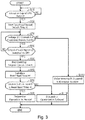
Fig. 3 is a flowchart of a state determination process. - With reference to
Figs. 1 to 3 , a description is hereinafter given of one embodiment in which a state determination device for a door lock device is formed in a door control unit. - A schematic configuration will be first described as to a door, a door opening-closing device, and a door lock device of a railway vehicle.
- As shown in
Fig. 1 , the railway vehicle includes a door withdoor leaves 10 that operate to open and close an opening, or a doorway of the railway vehicle. The door leaves 10 form a bi-parting door. The paireddoor leaves 10 are suspended withdoor suspending members 42 positioned above. Each of thedoor leaves 10 is provided with twodoor suspending members 42. Thedoor suspending members 42 slide alongrails 47 extending in the front-rear direction of the vehicle. The paireddoor leaves 10 constitute a sliding door with two leaves sliding in the front-rear direction of the vehicle. The paireddoor leaves 10 slide in directions away from each other and enter an open state to open the doorway, and slide in directions coming close to each other and enter a closed state to close the doorway. The railway vehicle includes a plurality of doorways each provided with a corresponding pair ofdoor leaves 10.Fig. 1 shows only one pair of door leaves 10 among a plurality of such pairs. - A door opening-
closing device 20 for driving thedoor leaves 10 is provided around, or more specifically, above the doorway of the railway vehicle. The door opening-closing device 20 includes anelectric motor 22 as a drive source. Theelectric motor 22 is coupled to the twodoor leaves 10 via adoor drive mechanism 24 that includes a rack and a pinion, for example. Specifically, thedoor drive mechanism 24 is coupled to outerdoor suspending members 42A among the twodoor suspending members 42 provided for each of thedoor leaves 10. The outerdoor suspending members 42A are positioned outside the doorway in the sliding direction of thedoor leaves 10. The door leaves 10 enter the open state when an output shaft of theelectric motor 22 rotates in one direction, and thedoor leaves 10 enter the closed state when the output shaft of theelectric motor 22 rotates in the other direction. - Above the doorway of the railway vehicle, there is provided a
door lock device 30 for locking the paireddoor leaves 10 in the fully closed state. Only onedoor lock device 30 is provided for each pair of thedoor leaves 10. Thedoor lock device 30 is positioned around the middle of the doorway in the sliding direction of thedoor leaves 10. - As shown in
Fig. 2 , thedoor lock device 30 includes asolenoid 32 as a drive source. Thesolenoid 32 includes acoil 33 having a cylindrical shape. A voltage from apower source 31 is applied to thecoil 33. Alock pin 34 shaped like a rod projects from inside thecoil 33. Thelock pin 34 is biased by acompression spring 36 in such a direction as to project from thecoil 33. Thesolenoid 32 includes a built-inammeter 39A for measuring an electric current A flowing through thecoil 33. A voltmeter 39B for measuring a voltage V of thepower source 31 is installed on the wire connecting between thepower source 31 and thecoil 33. - In the
door lock device 30, when a voltage is applied from thepower source 31 to thecoil 33 of thesolenoid 32 to excite thecoil 33, thelock pin 34 is withdrawn into thecoil 33 against the elastic force of thecompression spring 36. On the other hand, when no voltage is applied from thepower source 31 to thecoil 33 and thecoil 33 is demagnetized, thelock pin 34 is projected from thecoil 33 by the elastic force of thecompression spring 36. - As shown in
Fig. 1 , in thedoor lock device 30, thelock pin 34 is coupled to a projectingrod 37 via a coupling mechanism (not shown). The projectingrod 37 moves in accordance with the movement of thelock pin 34. Thedoor suspending members 42 provided for one of the paired door leaves 10 have a fixingmember 45 attached thereto. The fixingmember 45 is configured to engage with the projectingrod 37 when the door leaves 10 are in the fully closed state. The fixingmember 45 is attached to a middledoor suspending member 42B of one of the door leaves 10, which is one of the twodoor suspending members 42 provided for thisdoor leaf 10 and is positioned closer to the middle of the doorway in the sliding direction of the door leaves 10. - When the door leaves 10 are in the fully closed state, the
lock pin 34 projects from thecoil 33 in response to the demagnetization of thecoil 33 of thesolenoid 32, and thus the projectingrod 37 moves to engage with the fixingmember 45. As a result, the above one of the door leaves 10 enters a locked state in which thisdoor leaf 10 is prohibited from sliding. As onedoor leaf 10 is prohibited from sliding, theother door leaf 10 is also prohibited from sliding by thedoor drive mechanism 24. When thelock pin 34 is withdrawn into thecoil 33 in response to excitation of thecoil 33 of thesolenoid 32, the projectingrod 37 is disengaged from the fixingmember 45. The door leaves 10 then enter an unlocked state. - The movement of the
lock pin 34 is transmitted to a door lock switch (DLS) 38 via a transmission mechanism (not shown). As shown inFig. 2 , thedoor lock switch 38 outputs a lock signal LS as an output signal when thelock pin 34 is in a lock position where it projects from thecoil 33. Thedoor lock switch 38 stops outputting the lock signal LS as an output signal when thelock pin 34 moves into an unlock position where it is withdrawn into thecoil 33. In this way, thedoor lock switch 38 switches the output of the lock signal LS between On and Off depending on whether thedoor lock device 30 locks or unlocks the door leaves 10. - Next, an electrical configuration of the door opening-closing
device 20 and thedoor lock device 30 will be described. - As shown in
Fig. 1 , the door opening-closingdevice 20 and thedoor lock device 30 are controlled by adoor control unit 50. Thedoor control unit 50 is provided for each pair of the door leaves 10 and installed in the vicinity of the doorway of the railway vehicle. Thedoor control unit 50 may be formed of one or more processors that perform various processes in accordance with computer programs (software). Alternatively, thedoor control unit 50 may be formed of one or more dedicated hardware circuits such as microcomputers that perform at least a part of the various processes, or it may be formed of circuitry including a combination of such circuits. The processors include a CPU and a memory such as a RAM or ROM. The memory stores therein program codes or instructions configured to cause the CPU to perform processes. The memory, or a computer-readable medium, encompasses any kind of available media accessible by a general-purpose or dedicated computer. Thedoor control unit 50 also includes a non-volatile storage section. Thedoor control unit 50 receives the lock signal LS from thedoor lock switch 38. Thedoor control unit 50 also receives the values of the electric current A and the voltage V from theammeter 39A and the voltmeter 39B, respectively. - The
door control unit 50 is connected with avehicle control device 12 that serves as an upper-level device to control traveling of the railway vehicle and opening and closing of thedoor 10. As shown inFig. 2 , thedoor control unit 50 operates based on an instruction signal W from thevehicle control device 12. Thevehicle control device 12 may be formed of one or more processors that perform various processes in accordance with computer programs (software). Alternatively, thevehicle control device 12 may be formed of one or more dedicated hardware circuits such as microcomputers that perform at least a part of the various processes, or it may be formed of circuitry including a combination of such circuits. The processors include a CPU and a memory such as a RAM or ROM. The memory stores therein program codes or instructions configured to cause the CPU to perform processes. The memory, or a computer-readable medium, encompasses any kind of available media accessible by a general-purpose or dedicated computer. Thevehicle control device 12 also includes anon-volatile database 14. Thedatabase 14 intensively stores information input from thedoor control unit 50. - As shown in
Fig. 2 , thedoor control unit 50 includes adrive control section 52 for driving the door opening-closingdevice 20 and thedoor lock device 30 in accordance with the instruction signal W from thevehicle control device 12. Thedrive control section 52 outputs a drive signal for driving the door opening-closingdevice 20 and thedoor lock device 30. As a drive signal for driving unlock operation of thedoor lock device 30, thedrive control section 52 outputs to thepower source 31 an excitation signal EM1 for exciting thesolenoid 32. When the excitation signal EM1 is output, thepower source 31 applies a voltage to thesolenoid 32 to excite thesolenoid 32. As a drive signal for driving lock operation of thedoor lock device 30, thedrive control section 52 outputs to the power source 31 a demagnetization signal EM2 for demagnetizing thesolenoid 32. When the demagnetization signal EM2 is output, thepower source 31 stops applying a voltage to thesolenoid 32 to demagnetize thesolenoid 32. - In the
door lock device 30, the movement of thelock pin 34 may undergo a large slide resistance due to clogging by foreign substances or partial wear. The slide resistance may also be enlarged in accordance with deformation of the vehicle body to which thedoor lock device 30 is attached. When the movement of thelock pin 34 undergoes a large slide resistance, thelock pin 34 may start moving at a delayed timing or move at a low speed after it starts moving, in response to the excitation signal EM1 or the demagnetization signal EM2 output to thesolenoid 32. To address this problem, thedoor control unit 50 includes astate determination device 60 for determining whether or not a malfunction is present in thedoor lock device 30. - In addition to the enlarged slide resistance mentioned above, the
door lock device 30 may undergo a fault such as a disconnection or a short circuit occurring in thesolenoid 32 or the electrical system connected thereto, resulting in a reduced electric current flowing through thesolenoid 32. This also causes thelock pin 34 to start moving at a delayed timing or move at a low speed after it starts moving. Thestate determination device 60 also determines whether or not such a malfunction is present. - The
state determination device 60 of thedoor control unit 50 includes acalculation section 61 for calculating the elapsed time from the time when a drive signal for driving thedoor lock device 30 is output to the time when the operation of thedoor lock device 30 in response to the drive signal is completed. Thecalculation section 61 calculates the elapsed time related to the unlock operation of thedoor lock device 30. Specifically, thecalculation section 61 calculates the elapsed unlock time H elapsed from the time when the excitation signal EM1 is output to thesolenoid 32 to the time when the withdrawal of thelock pin 34 into thecoil 33 is completed and the projectingrod 37 is disengaged from the fixingmember 45. In calculating the elapsed unlock time H, thecalculation section 61 regards the timing at which the lock signal LS output from thedoor lock switch 38 switches from On to Off as the time at which the withdrawal of thelock pin 34 into thecoil 33 is completed. - The
state determination device 60 of thedoor control unit 50 includes adetermination section 62 for determining whether or not a malfunction is present in thedoor lock device 30 based on the elapsed unlock time H. When the elapsed unlock time H is longer than a prescribed time H1 set previously, thedetermination section 62 determines that the movement of thelock pin 34 is delayed, that is, a malfunction is present in thedoor lock device 30. Further, when the resistance R obtained by dividing the voltage V of thepower source 31 by the electric current A flowing through thecoil 33 is different from a prescribed resistance RQ set previously, thedetermination section 62 determines that a fault has occurred in thesolenoid 32 or the electrical system connected thereto, that is, a malfunction is present in thedoor lock device 30. In this way, thedetermination section 62 determines whether a fault has occurred, based on the relationship between the electric current A and the voltage V. The prescribed resistance RQ mentioned above is calculated by previously investigating through an experiment or simulation the relationship between the voltage and the electric current occurring when the voltage is applied to thesolenoid 32. - The
determination section 62 calculates the prescribed time H1 as a reference value for determining whether or not a malfunction is present in thedoor lock device 30. Thedetermination section 62 calculates the prescribed time H1 based on values of the elapsed unlock time H related to a plurality ofdoor lock devices 30 installed on the same vehicle among a plurality of vehicles constituting a train. Thecalculation section 61, which has calculated the elapsed unlock time H, transmits the elapsed unlock time H to thevehicle control device 12. Thevehicle control device 12 stores the elapsed unlock time H on thedatabase 14. Thevehicle control device 12 receives the values of the elapsed unlock time H from the plurality ofdoor control units 50 installed on the railway vehicle. Thedatabase 14 stores data on the elapsed unlock time H related to the plurality ofdoor lock devices 30 installed on the railway vehicle. This data covers a previous predetermined period. In calculating the prescribed time H1, thedetermination section 62 accesses thedatabase 14 of thevehicle control device 12 to obtain data on the elapsed unlock time H related to the plurality ofdoor lock devices 30 installed on the same vehicle, covering the previous predetermined period. Thedetermination section 62 then calculates the average time from the obtained data and calculates the prescribed time H1 such that it is longer than the average time. - Next, a state determination process performed by the
door control unit 50 will be described. Upon receiving from thevehicle control device 12 the instruction signal W for opening the door leaves 10, thedoor control unit 50 starts the state determination process including a series of steps. At the time when thedoor control unit 50 receives from thevehicle control device 12 the instruction signal W for opening the door leaves 10, the door leaves 10 are in the fully closed state, and thelock pin 34 is in the lock position where it projects from thecoil 33. In addition, thedoor lock switch 38 is outputting the lock signal LS. - As shown in
Fig. 3 , thedoor control unit 50 starts the state determination process in step S10. In step S10, thecalculation section 61 of thedoor control unit 50 determines whether or not the excitation signal EM1 has been output from thedrive control section 52 to thesolenoid 32. When the excitation signal EM1 has not been output (NO in step S10), thecalculation section 61 executes step S10 again. Thecalculation section 61 repeats step S10 until the excitation signal EM1 is output. When the excitation signal EM1 has been output (YES in step S10), thecalculation section 61 proceeds to step S20. - In step S20, the
calculation section 61 starts counting the lock time H. Thecalculation section 61 proceeds to step S30. In step S30, thedetermination section 62 refers to the measurement results of theammeter 39A and the voltmeter 39B. Thedetermination section 62 then determines whether or not the resistance R obtained by dividing the voltage V by the electric current A is equal to the prescribed resistance RQ. When the resistance R is different from the prescribed resistance RQ (R≠RQ) (NO in step S30), thedetermination section 62 proceeds to step S100. - In step S100, the
determination section 62 determines that a fault has occurred in the electrical system related to thesolenoid 32. Thedetermination section 62 then outputs to thevehicle control device 12 first information J1 indicating that a fault has occurred in the electrical system related to thesolenoid 32. Upon receiving the first information J1, thevehicle control device 12 stores on thedatabase 14 the information indicating that a fault has occurred in the electrical system related to thesolenoid 32. After executing step S100, thedetermination section 62 temporarily ends execution of the series of steps of the state determination process. - In step S30, when the resistance R is equal to the prescribed resistance RQ (R=RQ) (YES in step S30), the
determination section 62 proceeds to step S40. In step S40, thecalculation section 61 determines whether or not the output of the lock signal LS has been switched to Off. When the lock signal LS is being continuously output (NO in step S40), thecalculation section 61 returns to step S30. Thedetermination section 62 then executes step S30. Thecalculation section 61 and thedetermination section 62 repeat step S30 and step S40 until the output of the lock signal LS is switched to Off. When the output of the lock signal LS has been switched to Off (YES in step S40), thecalculation section 61 proceeds to step S50. - In step S50, the
calculation section 61 ends the count of the lock time H that was started in step S20. Thecalculation section 61 then calculates the final elapsed unlock time H at the elapsed unlock time H as of the time when step S50 is reached. Thecalculation section 61 transmits the calculated elapsed unlock time H to thevehicle control device 12. Subsequently, thecalculation section 61 proceeds to step S60. - In step S60, the
determination section 62 of thedoor control unit 50 calculates the prescribed time H1. As already described, thedetermination section 62 calculates the prescribed time H1 based on the values of the elapsed unlock time H related to a plurality ofdoor lock devices 30 installed on the same vehicle. Subsequently, thedetermination section 62 proceeds to step S70. Step S60 corresponds to the calculation step and the calculation process. - In step S70, the
determination section 62 determines whether the elapsed unlock time H is equal to or shorter than the prescribed time H1. When the elapsed unlock time H is longer than the prescribed time H1 (H>H1) (NO in step S70), thedetermination section 62 proceeds to step S110. - In step S110, the
determination section 62 determines that the movement of thelock pin 34 is delayed. Thedetermination section 62 then outputs to thevehicle control device 12 second information J2 indicating that the movement of thelock pin 34 is delayed. Upon receiving the second information J2, thevehicle control device 12 stores on thedatabase 14 the information indicating that the movement of thelock pin 34 is delayed. After executing step S110, thedetermination section 62 temporarily ends execution of the series of steps of the state determination process. - On the other hand, in step S70, when the elapsed unlock time H is equal to or shorter than the prescribed time H1 (H≤H1), the
determination section 62 proceeds to step S80. In step S80, thedetermination section 62 determines that thedoor lock device 30 is operating normally. After executing step S80, thedetermination section 62 temporarily ends execution of the series of steps of the state determination process. Steps S70, S80, and S110 correspond to the determination process and the determination step. - The information related to the fault in the electrical system and the delay in movement of the
lock pin 34 that is stored on thedatabase 14 of thevehicle control device 12 is read out, for example, by a worker inspecting the railway vehicle and is utilized for replacement or repair of thedoor lock device 30. - Operation in the embodiment will be now described. While the door leaves 10 are locked, the
lock pin 34 projects from thecoil 33 and the projectingrod 37 engages with the fixingmember 45. In addition, the output of the lock signal LS from thedoor lock switch 38 remains On. In this state, thedoor control unit 50 receives an instruction signal W for opening the door, and then thedrive control section 52 of thedoor control unit 50 outputs the excitation signal EM1 to thesolenoid 32. In response to the excitation signal EM1, thesolenoid 32 is excited and thelock pin 34 is withdrawn into thecoil 33. As thelock pin 34 is withdrawn, the output of the lock signal LS from thedoor lock switch 38 is switched to Off. - Advantageous effects of the embodiment will be now described. (1) In the state determination process, it is determined whether or not the elapsed unlock time H required for the unlock operation of the
door lock device 30 is within the prescribed time H1. When the elapsed unlock time H is longer than the prescribed time H1, it is determined that the movement of thelock pin 34 is delayed. This determination makes it possible to detect a malfunction of thedoor lock device 30. - (2) A malfunction of the
door lock device 30 may be caused by a fault in the electrical system, in addition to an enlarged slide resistance. With this taken into account, the state determination process employs two-stage determination. The first stage is to determine whether or not the relationship between the voltage V of thepower source 31 and the electric current A flowing through thecoil 33 is appropriate. It is thus confirmed whether or not a fault has occurred in the electrical system related to thesolenoid 32. When no fault has occurred in the electrical system, then it is determined whether or not the elapsed unlock time H required for the unlock operation of thedoor lock device 30 is within the prescribed time H1. Confirming that no fault has occurred in the electrical system, it is thus determined whether or not the movement of thelock pin 34 is delayed. Accordingly, when it is determined that the movement of thelock pin 34 is delayed, it can be presumed that such a delay is caused by an enlarged slide resistance. In this way, the state determination process makes it possible not only to detect a malfunction of thedoor lock device 30, but also to distinguish the causes of the malfunction of thedoor lock device 30. - (3) The
door lock switch 38, which is an existing component, is used to confirm completion of the unlock operation of thelock pin 34, and therefore, it is not necessary to add a new peculiar component such as a camera for monitoring the movement of thelock pin 34 to confirm completion of the unlock operation of thelock pin 34. It is thus possible to avoid increase of the number of components for detecting a malfunction of thedoor lock device 30. - (4) A fault in the
solenoid 32 and the electrical system connected thereto may cause delayed movement of thelock pin 34. Therefore, it is important to grasp the state of the electrical system in order to grasp the state of thedoor lock device 30. Since thesolenoid 32 is excited for the unlock operation of thelock pin 34, it is possible to obtain information related to the electric current A flowing through thecoil 33 of thesolenoid 32. Accordingly, it is possible to detect a fault in thesolenoid 32 and the electrical system connected thereto. - (5) The
determination section 62 calculates the prescribed time H1 based on the values of the elapsed unlock time H related to a plurality ofdoor lock devices 30 installed on the same vehicle. Although the plurality ofdoor lock devices 30 installed on the same vehicle deteriorate to slightly different degrees in accordance with the loads imparted thereto, it can be presumed that thesedoor lock devices 30 as a whole have deteriorated to similar degrees since they were new. Since the prescribed time H1 is calculated based on thedoor lock devices 30 having deteriorated to similar degrees so as to be used for comparison between them, it is possible to determine whether or not a malfunction is present in thedoor lock device 30 irrespective of its degree of deterioration. Further, since the prescribed time H1 is calculated from thedoor lock devices 30 on the same vehicle, it is not necessary to previously perform an experiment or simulation for calculating the prescribed time H1, and therefore, the effort of performing such an experiment or simulation can be eliminated. - The above embodiment can be modified as described below. The above embodiment and the following modifications can be implemented in combination to the extent where they are technically consistent with each other.
- The method of calculating the prescribed time H1 is not limited to the example in the above embodiment. The prescribed time H1 has a length with which to determine a delay in movement of the
lock pin 34, and specifically a length with which to determine a relatively slight delay in movement that does not affect the safe operation of the railway vehicle. - The prescribed time H1 may be calculated based on the elapsed unlock time H of the door lock devices on a plurality or all of the vehicles included in a train.
- The prescribed time H1 may be calculated based on the elapsed unlock time H of only the door lock devices that satisfy a condition, not based on the elapsed unlock time H of all the door lock devices, among the door lock devices installed on the same vehicle or a plurality of vehicles included in a train. For example, with values of the elapsed unlock time H of a plurality of door lock devices sorted from the shortest one, the prescribed time H1 may be calculated as an average of a plurality of top-sorted values of the elapsed unlock time H.
- When the difference between the loads imparted to the doors is previously known, the prescribed time H1 may be calculated based on the elapsed unlock time H of the door lock devices of the doors subjected to a load of the same degree.
- A fixed prescribed time H1 may be previously calculated by an experiment or simulation.
- The determination of a fault in the electrical system related to the
solenoid 32 may be based on only one of the voltage V of thepower source 31 and the electric current A flowing through thesolenoid 32. For example, it is possible to monitor the time series of the electric current A flowing through thesolenoid 32 while a voltage is applied to thesolenoid 32, and determine that a fault has occurred in the electrical system related to thesolenoid 32 when the variation of the electric current A is excessively large, or when the electric current A is instable. - It is not necessary to determine a fault in the electrical system related to the
solenoid 32 at the timing of the unlock operation of thedoor lock device 30. Only a delay in movement of thelock pin 34 may be determined at the timing of the unlock operation of thedoor lock device 30. - It is possible to determine whether or not a malfunction is present in the
door lock device 30 at the timing of the lock operation of thedoor lock device 30. In the lock operation of thedoor lock device 30, thesolenoid 32 is demagnetized, unlike the unlock operation of thedoor lock device 30. In other words, no voltage is applied to thesolenoid 32 in the lock operation of thedoor lock device 30, and therefore, information related to the electrical system such as the voltage V cannot be obtained in the lock operation of thedoor lock device 30. Accordingly, a fault in the electrical system related to thesolenoid 32 cannot be detected at the timing of the lock operation of thedoor lock device 30. However, a delay in movement of thelock pin 34 can be detected in the lock operation of thedoor lock device 30. Specifically, while the door leaves 10 operate from the open state to the closed state prior to the lock operation of thedoor lock device 30, thesolenoid 32 is excited and thelock pin 34 is withdrawn in thecoil 33. When the door leaves 10 are in the fully closed state, thesolenoid 32 is demagnetized, such that thelock pin 34 projects from thecoil 33 by the elastic force of thecompression spring 36, and the projectingrod 37 engages with the fixingmember 45. - To determine whether or not a malfunction is present in the
door lock device 30 using the above lock operation, an elapsed lock time is compared with a prescribed time for the lock operation. The elapsed lock time is counted from the time when the demagnetization signal EM2 is output to thesolenoid 32 to the time when thelock pin 34 completes projecting from thecoil 33 and thedoor lock switch 38 switches to On. This makes it possible to determine whether or not the movement of thelock pin 34 is delayed. For example, it is possible to make determination related to an elapsed time in both the lock operation and the unlock operation of thedoor lock device 30, so as to doubly monitor at least a delay in movement of thelock pin 34. - The configuration of the
door lock device 30 is not limited to the example in the above embodiment. For example, the movement of thelock pin 34 may be transmitted directly to thedoor lock switch 38 without a medium of a transmission mechanism. Further, thelock pin 34 may engage directly with the door leaves 10 to lock the door leaves 10. - The
door lock device 30 may be modified such that thelock pin 34 is withdrawn by a tension spring into thesolenoid 32 upon demagnetization of thesolenoid 32, and thelock pin 34 projects from thesolenoid 32 upon excitation of thesolenoid 32. It is also possible that thesolenoid 32 alone drives the reciprocation of thelock pin 34 without use of a spring for return. - The door lock device may be configured such that the unlocked state and the locked state of the door leaves 10 are controlled in accordance with the
electric motor 22 for driving the opening and closing of the door leaves 10. In such configuration, the unlock operation of the door lock device and the opening operation of the door leaves 10 are performed as a series of operations in response to a drive signal for rotating the output shaft of theelectric motor 22 in one direction. Specifically, when the door leaves 10 are in the fully closed state, the output shaft of theelectric motor 22 rotates in one direction. At this time, the door lock device first operates such that the door leaves 10 enter the unlocked state, and then the door leaves 10 enter the open state. On the other hand, the closing operation of the door leaves 10 and the lock operation of the door lock device are performed as a series of operations in response to a drive signal for rotating the output shaft of theelectric motor 22 in the other direction. Specifically, when the door leaves 10 are in the open state, the output shaft of theelectric motor 22 rotates in the other direction. At this time, the door leaves 10 first enter the closed state, and then the door lock device operates such that the door leaves 10 enter the locked state. In this door lock device, the drive signal for rotating the output shaft of theelectric motor 22 in one direction serves as both the drive signal for driving the unlock operation of the door lock device and the drive signal for opening the door leaves 10. Also, the drive signal for rotating the output shaft of theelectric motor 22 in the other direction serves as both the drive signal for closing the door leaves 10 and the drive signal for driving the lock operation of the door lock device. - In the lock operation of the above door lock device, when the drive signal for rotating the output shaft of the
electric motor 22 in the other direction is output, the door leaves 10 are first closed. Therefore, the elapsed time from the time when the above drive signal is output to theelectric motor 22 to the time when the lock operation of the door lock device is completed includes the elapsed time for the closing operation of the door leaves 10. To confirm whether or not a malfunction related to the lock operation of the door lock device is present, it is possible to use a detection signal from the door closing switch (DCS) for detecting closing of the door leaves 10. Specifically, an elapsed door closing time from the time when the drive signal is output to the time when the door closing switch detects closing of the door leaves 10 is calculated separately from the elapsed time from the time when the drive signal is output to the time when the lock operation of the door lock device is completed. The elapsed door closing time is added to a prescribed lock time determined previously by an experiment or the like as a prescribed time related to the lock operation of the door lock device, thereby to obtain the prescribed time. The elapsed time from the time when the drive signal is output to the time when the lock operation of the door lock device is completed is compared with the prescribed time. When the elapsed time is longer than the prescribed time, it is determined that the operation of the door lock device is delayed. It is also possible to determine that the operation of the door lock device is delayed when the above elapsed time subtracted by the elapsed door closing time is longer than the prescribed lock time. - In the unlock operation of the above door lock device, when the drive signal is output to the
electric motor 22, the door lock device first operates without the medium of the operation of the door leaves 10. Accordingly, the elapsed time related to the unlock operation of the door lock device can be obtained accurately by calculating the elapsed time from the time when the drive signal is output to theelectric motor 22 to the time when the door lock switch is switched to Off. As a result, it is possible to determine whether or not the operation of the door lock switch is delayed based on the above elapsed time. Further, it is also possible to detect a fault in the electric motor and the electrical system connected thereto by sensing the voltage applied to theelectric motor 22 and the electric current flowing through theelectric motor 22 during the lock operation and the unlock operation of the door lock device. - The method of determining the timing of completion of the lock operation or the unlock operation of the door lock device does not necessarily use the door lock switch. For example, a camera for monitoring the movement of the lock pin may be used to determine the timing of completion of the lock operation or the unlock operation of the door lock device.
- A notification lamp or a buzzer for notifying a malfunction in the
door lock device 30 may be provided on the driver's cab, for example. When a delay in the operation of thelock pin 34 or a fault in the electrical system is detected, the notification lamp or the buzzer may be actuated. - A dedicated server may be provided outside the railway vehicle, and the dedicated server may serve as a database that intensively stores information input from the
door control unit 50. Thedoor control unit 50 may be connected to the server via an external communication network, and thedoor control unit 50 may transmit to the server various information such as related to whether or not a malfunction is present in thedoor lock device 30 or related to the elapsed unlock time H. - The storage section of the
door control unit 50 may store information such as related to whether or not a malfunction is present in thedoor lock device 30 controlled by thedoor control unit 50 or related to the elapsed unlock time H. For example, a plurality ofdoor control units 50 may be connected with each other to exchange information, such that it is no longer necessary to read information from thedatabase 14 for calculation of the prescribed time H1. - A computer that serves as the state determination device for the door lock device is not limited to the
door control unit 50. For example, thevehicle control device 12 or a server outside the railway vehicle may serve as the state determination device for the door lock device. The computer serving as the state determination device may obtain information related to the timing at which the drive signal for driving the door lock device is output and the timing at which the operation of the door lock device is completed, such that the computer can calculate the elapsed unlock time and the elapsed lock time. When the elapsed unlock time or the elapsed lock time calculated is longer than the respective prescribed time, the computer serving as the state determination device may determine that a malfunction is present in the door lock device. In this configuration, the computer serving as the state determination device includes the calculation section and the determination section. - For example, when the
vehicle control device 12 is used as the state determination device, the instruction signal W output from thevehicle control device 12 may be handled as the drive signal for driving the door lock device. Suppose that the door lock device uses the solenoid described for the above embodiment. In this case, when the door leaves 10 are in the fully closed state, thevehicle control device 12 outputs the instruction signal W for opening the door leaves 10. Thedoor control unit 50 receives the instruction signal W and outputs the excitation signal EM1 for the unlock operation of thedoor lock device 30. The output of the lock signal LS from thedoor lock switch 38 is then switched to Off, and information indicating this switching is output to thevehicle control device 12. In this process, thevehicle control device 12 calculates the elapsed time from the time when it output the instruction signal Wto the time when it received the information indicating that the lock signal LS has been switched to Off, and it compares the elapsed time with the prescribed time to determine whether or not a malfunction is present in thedoor lock device 30. The prescribed time used in this case is set taking account of the elapsed time from the time when thevehicle control device 12 output the instruction signal W to the time when the signal is received by thedoor control unit 50, and the elapsed time until the information indicating that the lock signal LS has been switched to Off is input to thevehicle control device 12. - In the above case where the instruction signal W output from the
vehicle control device 12 is handled as the drive signal for driving the door lock device, it is determined at the timing of the lock operation of the door lock device whether or not a malfunction is present in the door lock device. When the door leaves 10 are in the open state, thevehicle control device 12 outputs the instruction signal W for closing the door leaves 10. Thedoor control unit 50 receives the instruction signal W and first drives the door leaves 10 for the closing operation. After the door leaves 10 are fully closed, thedoor control unit 50 drives thedoor lock device 30 for the lock operation. The output of the lock signal LS from thedoor lock switch 38 is then switched to On, and information indicating this switching is output to thevehicle control device 12. The elapsed time from the time when thevehicle control device 12 outputs the instruction signal Wto the time when thevehicle control device 12 receives the information indicating that the lock signal LS has been switched to On includes the elapsed time during the closing operation of the door leaves 10. Therefore, in the case where the instruction signal W output from thevehicle control device 12 is handled as the drive signal for driving the door lock device, the detection signal of the door closing switch described above can be used. Specifically, the detection signal of the door closing switch can be used to calculate the elapsed door closing time from the time when the instruction signal W is output to the time when the door leaves are closed, such that it can be confirmed whether or not the lock operation of the door lock device is delayed, as with the modification in which the rotation of theelectric motor 22 drives the door leaves 10 for closing operation and also drives the door lock device for the lock operation. - In the case where, as with the above modification, it is determined whether or not a malfunction is present in the door lock device based on the elapsed time from the time when the
vehicle control device 12 outputs the instruction signal Wto the time when the operation of the door lock device is completed, the above elapsed time may be calculated on a server outside the railway vehicle to determine whether or not a malfunction is present in the door lock device. - The door may be a single sliding door. That is, it is possible to determine whether or not a malfunction is present in a door lock device for locking a single sliding door.
- The method of determining a malfunction in the door lock device is based on the elapsed time from the time when the drive signal is output to the time when the lock operation or the unlock operation of the door lock device is completed, but this method dot not necessarily include comparison between the elapsed time and the prescribed time. For example, values of the elapsed time obtained each time the door is opened or closed are sorted to monitor the change (the trend of change) of the length of the elapsed time. When, for example, the trend of change exceeds a predetermined increase rate, it may be determined that a malfunction is present in the door lock device. Alternatively, when the rate of change between values of the elapsed time obtained at two sequential timings exceeds a reference value, it may be determined that a malfunction is present in the door lock device.
-
- 12
- vehicle control device
- 30
- door lock device
- 32
- solenoid
- 34
- lock pin
- 38
- door lock switch
- 50
- door control unit
- 60
- state determination device
- 61
- calculation section
- 62
- determination section
Claims (8)
- A state determination device (60) for a door lock device (30), comprising:a calculation section (61) for calculating an elapsed time from a time when a drive signal for driving a door lock device (30) is output to a time when lock operation or unlock operation of the door lock device (30) is completed; anda determination section (62) for determining whether or not a malfunction is present in the door lock device (30) based on the elapsed time.
- The state determination device (60) for a door lock device (30) according to claim 1, wherein the calculation section (61) calculates the elapsed time with a timing at which operation of the door lock device (30) is completed defined as a timing at which, after the drive signal is output, an output signal of a door lock switch (38) is switched between a state in which the door lock device (30) locks a door leaf (10) and a state in which the door lock device (30) unlocks the door leaf (10).
- The state determination device (60) for a door lock device (30) according to claim 1 or 2, wherein the calculation section (61) calculates the elapsed time for the unlock operation of the door lock device (30).
- The state determination device (60) for a door lock device (30) according to any one of claims 1 to 3, wherein when the elapsed time is longer than a prescribed time, the determination section (62) determines that a malfunction is present in the door lock device (30).
- The state determination device (60) for a door lock device (30) according to claim 4, wherein a railway vehicle has a plurality of door lock devices (30) installed thereon, and wherein the determination section (62) calculates the prescribed time based on values of the elapsed time related to the plurality of door lock devices (30) installed on the same railway vehicle.
- A state determination method for a door lock device (30), comprising:a calculation step (S10, S20, S40, S50) of calculating an elapsed time from a time when a drive signal for driving a door lock device (30) is output to a time when operation of the door lock device (30) is completed; anda determination step (S70, S80, S110) of determining whether or not a malfunction is present in the door lock device (30) based on the elapsed time.
- A state determination program for a door lock device (30), the state determination program causing a computer to perform:a calculation process for calculating an elapsed time from a time when a drive signal for driving a door lock device (30) is output to a time when operation of the door lock device (30) is completed; anda determination process for determining whether or not a malfunction is present in the door lock device (30) based on the elapsed time.
- A computer-readable storage medium storing a state determination program for a door lock device, wherein when executed by a computer, the state determination program causes the computer to perform:a calculation process for calculating an elapsed time from a time when a drive signal for driving a door lock device (30) is output to a time when operation of the door lock device (30) is completed; anda determination process for determining whether or not a malfunction is present in the door lock device (30) based on the elapsed time.
Applications Claiming Priority (1)
| Application Number | Priority Date | Filing Date | Title |
|---|---|---|---|
| JP2019197253A JP7360897B2 (en) | 2019-10-30 | 2019-10-30 | Door lock device status determination device, door lock device status determination method, and door lock device status determination program |
Publications (2)
| Publication Number | Publication Date |
|---|---|
| EP3816376A1 true EP3816376A1 (en) | 2021-05-05 |
| EP3816376B1 EP3816376B1 (en) | 2024-12-04 |
Family
ID=73172446
Family Applications (1)
| Application Number | Title | Priority Date | Filing Date |
|---|---|---|---|
| EP20202278.6A Active EP3816376B1 (en) | 2019-10-30 | 2020-10-16 | State determination device for door lock device, state determination method for door lock device, and state determination program for door lock device |
Country Status (3)
| Country | Link |
|---|---|
| EP (1) | EP3816376B1 (en) |
| JP (1) | JP7360897B2 (en) |
| CN (1) | CN112746783B (en) |
Cited By (3)
| Publication number | Priority date | Publication date | Assignee | Title |
|---|---|---|---|---|
| FR3134594A1 (en) * | 2022-04-14 | 2023-10-20 | Psa Automobiles Sa | Method and device for determining a locking state of a vehicle |
| EP4390018A1 (en) * | 2022-12-21 | 2024-06-26 | Bode - Die Tür GmbH | Door system with temporal monitoring of locks |
| CN119321898A (en) * | 2024-08-30 | 2025-01-17 | 赛力斯汽车有限公司 | Automatic door handle testing method for vehicle |
Families Citing this family (2)
| Publication number | Priority date | Publication date | Assignee | Title |
|---|---|---|---|---|
| CN113793435B (en) * | 2021-09-13 | 2023-07-21 | 东屋世安物联科技(江苏)股份有限公司 | Unlocking method and device of multi-locking execution mechanism, locking system and safe |
| CN114517613B (en) * | 2022-01-24 | 2023-02-24 | 中国第一汽车股份有限公司 | Closing method and control device of electric suction door and vehicle |
Citations (3)
| Publication number | Priority date | Publication date | Assignee | Title |
|---|---|---|---|---|
| JPH0721777U (en) | 1993-09-21 | 1995-04-21 | 豊和工業株式会社 | Card dropping device |
| JP2002038796A (en) * | 2000-07-25 | 2002-02-06 | Asmo Co Ltd | Method for preventing pinching in door locking / unlocking device and door locking / unlocking device |
| EP3656642A2 (en) * | 2018-11-08 | 2020-05-27 | Nabtesco Corporation | Notification device and door opening-closing device |
Family Cites Families (7)
| Publication number | Priority date | Publication date | Assignee | Title |
|---|---|---|---|---|
| JPH01214679A (en) * | 1988-02-23 | 1989-08-29 | Yamatake Honeywell Co Ltd | Electric lock state detector |
| JPH0650037A (en) * | 1992-07-27 | 1994-02-22 | Mitsubishi Electric Corp | Electric lock control device |
| AT501893B1 (en) * | 2005-08-01 | 2006-12-15 | Knorr Bremse Gmbh | METHOD AND DEVICE FOR EXTERIOR OPERATION OF DEFECTIVE DOORS |
| JP5085466B2 (en) * | 2008-08-20 | 2012-11-28 | 株式会社日立ビルシステム | Electric lock abnormality detection system |
| CN102011537B (en) * | 2010-11-23 | 2012-05-23 | 上海海事大学 | Subway anti-clamp safety door |
| CN202559116U (en) * | 2012-04-09 | 2012-11-28 | 松下家电研究开发(杭州)有限公司 | A control system of a machine cover lock assembly and a washing machine provided with the control system |
| CN106320852B (en) * | 2016-11-11 | 2018-08-07 | 北京经纬恒润科技有限公司 | A kind of electric door lock fault handling method and device |
-
2019
- 2019-10-30 JP JP2019197253A patent/JP7360897B2/en active Active
-
2020
- 2020-10-16 EP EP20202278.6A patent/EP3816376B1/en active Active
- 2020-10-28 CN CN202011172659.7A patent/CN112746783B/en active Active
Patent Citations (3)
| Publication number | Priority date | Publication date | Assignee | Title |
|---|---|---|---|---|
| JPH0721777U (en) | 1993-09-21 | 1995-04-21 | 豊和工業株式会社 | Card dropping device |
| JP2002038796A (en) * | 2000-07-25 | 2002-02-06 | Asmo Co Ltd | Method for preventing pinching in door locking / unlocking device and door locking / unlocking device |
| EP3656642A2 (en) * | 2018-11-08 | 2020-05-27 | Nabtesco Corporation | Notification device and door opening-closing device |
Cited By (3)
| Publication number | Priority date | Publication date | Assignee | Title |
|---|---|---|---|---|
| FR3134594A1 (en) * | 2022-04-14 | 2023-10-20 | Psa Automobiles Sa | Method and device for determining a locking state of a vehicle |
| EP4390018A1 (en) * | 2022-12-21 | 2024-06-26 | Bode - Die Tür GmbH | Door system with temporal monitoring of locks |
| CN119321898A (en) * | 2024-08-30 | 2025-01-17 | 赛力斯汽车有限公司 | Automatic door handle testing method for vehicle |
Also Published As
| Publication number | Publication date |
|---|---|
| CN112746783A (en) | 2021-05-04 |
| EP3816376B1 (en) | 2024-12-04 |
| JP7360897B2 (en) | 2023-10-13 |
| CN112746783B (en) | 2022-09-23 |
| JP2021070954A (en) | 2021-05-06 |
Similar Documents
| Publication | Publication Date | Title |
|---|---|---|
| EP3816376B1 (en) | State determination device for door lock device, state determination method for door lock device, and state determination program for door lock device | |
| EP1852382B1 (en) | Elevator apparatus | |
| KR101186641B1 (en) | Apparatus and method for dually controlling automatic door | |
| TWI747066B (en) | Notification device and door switch device | |
| US9382746B2 (en) | Door control device | |
| US10960921B2 (en) | Lash detection startup diagnostic | |
| EP1792864B1 (en) | Elevator apparatus | |
| CN106932707B (en) | Test the method, apparatus and product of digital circuit | |
| US12345744B2 (en) | Diagnosis system and diagnosis method for opening/closing device | |
| CN111356816A (en) | Method and apparatus for identifying wear status of components of a door drive system of a rail vehicle | |
| US10604970B2 (en) | Method to detect end-of-life in latches | |
| DE102018211304A1 (en) | motor control | |
| CN107966979A (en) | Electric back door ECU tests system and test method | |
| CN107643117B (en) | load profile | |
| US12024934B2 (en) | Opening and closing member control device and opening and closing member control method | |
| JPH072450A (en) | Elevator control operation device | |
| CN106094791A (en) | Vehicle Controller and acquisition methods fault time, diagnostic system and automobile | |
| EP4668239A1 (en) | System comprising an electronic door latch arrangement for a vehicle | |
| JP6384712B2 (en) | Control device and vehicle control system | |
| CN119321898B (en) | Automatic door handle testing method for vehicle | |
| DE102020205217A1 (en) | Method and control system for maintaining the door mechanism of an elevator installation | |
| JPS61130193A (en) | Detector for abnormality of door for elevator | |
| DE102020205220A1 (en) | Method and system for maintenance of the door mechanism of an elevator installation | |
| JP2590277B2 (en) | System test equipment | |
| KR101675200B1 (en) | Apparatus and method for diagnosing relay coil control circuit |
Legal Events
| Date | Code | Title | Description |
|---|---|---|---|
| PUAI | Public reference made under article 153(3) epc to a published international application that has entered the european phase |
Free format text: ORIGINAL CODE: 0009012 |
|
| STAA | Information on the status of an ep patent application or granted ep patent |
Free format text: STATUS: REQUEST FOR EXAMINATION WAS MADE |
|
| 17P | Request for examination filed |
Effective date: 20201016 |
|
| AK | Designated contracting states |
Kind code of ref document: A1 Designated state(s): AL AT BE BG CH CY CZ DE DK EE ES FI FR GB GR HR HU IE IS IT LI LT LU LV MC MK MT NL NO PL PT RO RS SE SI SK SM TR |
|
| STAA | Information on the status of an ep patent application or granted ep patent |
Free format text: STATUS: EXAMINATION IS IN PROGRESS |
|
| 17Q | First examination report despatched |
Effective date: 20230526 |
|
| P01 | Opt-out of the competence of the unified patent court (upc) registered |
Effective date: 20230523 |
|
| GRAP | Despatch of communication of intention to grant a patent |
Free format text: ORIGINAL CODE: EPIDOSNIGR1 |
|
| STAA | Information on the status of an ep patent application or granted ep patent |
Free format text: STATUS: GRANT OF PATENT IS INTENDED |
|
| RIC1 | Information provided on ipc code assigned before grant |
Ipc: E05B 83/36 20140101ALN20240322BHEP Ipc: E05B 81/74 20140101ALN20240322BHEP Ipc: E05B 81/72 20140101ALN20240322BHEP Ipc: E05B 47/00 20060101ALN20240322BHEP Ipc: G07C 1/32 20060101ALI20240322BHEP Ipc: E05B 81/58 20140101AFI20240322BHEP |
|
| INTG | Intention to grant announced |
Effective date: 20240423 |
|
| GRAJ | Information related to disapproval of communication of intention to grant by the applicant or resumption of examination proceedings by the epo deleted |
Free format text: ORIGINAL CODE: EPIDOSDIGR1 |
|
| STAA | Information on the status of an ep patent application or granted ep patent |
Free format text: STATUS: EXAMINATION IS IN PROGRESS |
|
| GRAP | Despatch of communication of intention to grant a patent |
Free format text: ORIGINAL CODE: EPIDOSNIGR1 |
|
| STAA | Information on the status of an ep patent application or granted ep patent |
Free format text: STATUS: GRANT OF PATENT IS INTENDED |
|
| INTC | Intention to grant announced (deleted) | ||
| RAP3 | Party data changed (applicant data changed or rights of an application transferred) |
Owner name: NABTESCO CORPORATION |
|
| RIC1 | Information provided on ipc code assigned before grant |
Ipc: E05B 83/36 20140101ALN20240606BHEP Ipc: E05B 81/74 20140101ALN20240606BHEP Ipc: E05B 81/72 20140101ALN20240606BHEP Ipc: E05B 47/00 20060101ALN20240606BHEP Ipc: G07C 1/32 20060101ALI20240606BHEP Ipc: E05B 81/58 20140101AFI20240606BHEP |
|
| RIN1 | Information on inventor provided before grant (corrected) |
Inventor name: YAMADA, SHINSUKE |
|
| INTG | Intention to grant announced |
Effective date: 20240624 |
|
| GRAS | Grant fee paid |
Free format text: ORIGINAL CODE: EPIDOSNIGR3 |
|
| GRAA | (expected) grant |
Free format text: ORIGINAL CODE: 0009210 |
|
| STAA | Information on the status of an ep patent application or granted ep patent |
Free format text: STATUS: THE PATENT HAS BEEN GRANTED |
|
| AK | Designated contracting states |
Kind code of ref document: B1 Designated state(s): AL AT BE BG CH CY CZ DE DK EE ES FI FR GB GR HR HU IE IS IT LI LT LU LV MC MK MT NL NO PL PT RO RS SE SI SK SM TR |
|
| REG | Reference to a national code |
Ref country code: CH Ref legal event code: EP |
|
| REG | Reference to a national code |
Ref country code: DE Ref legal event code: R096 Ref document number: 602020042401 Country of ref document: DE |
|
| REG | Reference to a national code |
Ref country code: IE Ref legal event code: FG4D |
|
| REG | Reference to a national code |
Ref country code: LT Ref legal event code: MG9D |
|
| REG | Reference to a national code |
Ref country code: NL Ref legal event code: MP Effective date: 20241204 |
|
| PG25 | Lapsed in a contracting state [announced via postgrant information from national office to epo] |
Ref country code: HR Free format text: LAPSE BECAUSE OF FAILURE TO SUBMIT A TRANSLATION OF THE DESCRIPTION OR TO PAY THE FEE WITHIN THE PRESCRIBED TIME-LIMIT Effective date: 20241204 |
|
| PG25 | Lapsed in a contracting state [announced via postgrant information from national office to epo] |
Ref country code: FI Free format text: LAPSE BECAUSE OF FAILURE TO SUBMIT A TRANSLATION OF THE DESCRIPTION OR TO PAY THE FEE WITHIN THE PRESCRIBED TIME-LIMIT Effective date: 20241204 |
|
| PG25 | Lapsed in a contracting state [announced via postgrant information from national office to epo] |
Ref country code: BG Free format text: LAPSE BECAUSE OF FAILURE TO SUBMIT A TRANSLATION OF THE DESCRIPTION OR TO PAY THE FEE WITHIN THE PRESCRIBED TIME-LIMIT Effective date: 20241204 |
|
| PG25 | Lapsed in a contracting state [announced via postgrant information from national office to epo] |
Ref country code: ES Free format text: LAPSE BECAUSE OF FAILURE TO SUBMIT A TRANSLATION OF THE DESCRIPTION OR TO PAY THE FEE WITHIN THE PRESCRIBED TIME-LIMIT Effective date: 20241204 |
|
| PG25 | Lapsed in a contracting state [announced via postgrant information from national office to epo] |
Ref country code: NO Free format text: LAPSE BECAUSE OF FAILURE TO SUBMIT A TRANSLATION OF THE DESCRIPTION OR TO PAY THE FEE WITHIN THE PRESCRIBED TIME-LIMIT Effective date: 20250304 |
|
| PG25 | Lapsed in a contracting state [announced via postgrant information from national office to epo] |
Ref country code: LV Free format text: LAPSE BECAUSE OF FAILURE TO SUBMIT A TRANSLATION OF THE DESCRIPTION OR TO PAY THE FEE WITHIN THE PRESCRIBED TIME-LIMIT Effective date: 20241204 Ref country code: GR Free format text: LAPSE BECAUSE OF FAILURE TO SUBMIT A TRANSLATION OF THE DESCRIPTION OR TO PAY THE FEE WITHIN THE PRESCRIBED TIME-LIMIT Effective date: 20250305 |
|
| PG25 | Lapsed in a contracting state [announced via postgrant information from national office to epo] |
Ref country code: RS Free format text: LAPSE BECAUSE OF FAILURE TO SUBMIT A TRANSLATION OF THE DESCRIPTION OR TO PAY THE FEE WITHIN THE PRESCRIBED TIME-LIMIT Effective date: 20250304 |
|
| PG25 | Lapsed in a contracting state [announced via postgrant information from national office to epo] |
Ref country code: NL Free format text: LAPSE BECAUSE OF FAILURE TO SUBMIT A TRANSLATION OF THE DESCRIPTION OR TO PAY THE FEE WITHIN THE PRESCRIBED TIME-LIMIT Effective date: 20241204 |
|
| REG | Reference to a national code |
Ref country code: AT Ref legal event code: MK05 Ref document number: 1748330 Country of ref document: AT Kind code of ref document: T Effective date: 20241204 |
|
| PG25 | Lapsed in a contracting state [announced via postgrant information from national office to epo] |
Ref country code: SM Free format text: LAPSE BECAUSE OF FAILURE TO SUBMIT A TRANSLATION OF THE DESCRIPTION OR TO PAY THE FEE WITHIN THE PRESCRIBED TIME-LIMIT Effective date: 20241204 |
|
| PG25 | Lapsed in a contracting state [announced via postgrant information from national office to epo] |
Ref country code: PL Free format text: LAPSE BECAUSE OF FAILURE TO SUBMIT A TRANSLATION OF THE DESCRIPTION OR TO PAY THE FEE WITHIN THE PRESCRIBED TIME-LIMIT Effective date: 20241204 |
|
| PG25 | Lapsed in a contracting state [announced via postgrant information from national office to epo] |
Ref country code: IS Free format text: LAPSE BECAUSE OF FAILURE TO SUBMIT A TRANSLATION OF THE DESCRIPTION OR TO PAY THE FEE WITHIN THE PRESCRIBED TIME-LIMIT Effective date: 20250404 |
|
| PG25 | Lapsed in a contracting state [announced via postgrant information from national office to epo] |
Ref country code: PT Free format text: LAPSE BECAUSE OF FAILURE TO SUBMIT A TRANSLATION OF THE DESCRIPTION OR TO PAY THE FEE WITHIN THE PRESCRIBED TIME-LIMIT Effective date: 20250404 |
|
| PG25 | Lapsed in a contracting state [announced via postgrant information from national office to epo] |
Ref country code: EE Free format text: LAPSE BECAUSE OF FAILURE TO SUBMIT A TRANSLATION OF THE DESCRIPTION OR TO PAY THE FEE WITHIN THE PRESCRIBED TIME-LIMIT Effective date: 20241204 |
|
| PG25 | Lapsed in a contracting state [announced via postgrant information from national office to epo] |
Ref country code: RO Free format text: LAPSE BECAUSE OF FAILURE TO SUBMIT A TRANSLATION OF THE DESCRIPTION OR TO PAY THE FEE WITHIN THE PRESCRIBED TIME-LIMIT Effective date: 20241204 Ref country code: AT Free format text: LAPSE BECAUSE OF FAILURE TO SUBMIT A TRANSLATION OF THE DESCRIPTION OR TO PAY THE FEE WITHIN THE PRESCRIBED TIME-LIMIT Effective date: 20241204 |
|
| PG25 | Lapsed in a contracting state [announced via postgrant information from national office to epo] |
Ref country code: SK Free format text: LAPSE BECAUSE OF FAILURE TO SUBMIT A TRANSLATION OF THE DESCRIPTION OR TO PAY THE FEE WITHIN THE PRESCRIBED TIME-LIMIT Effective date: 20241204 |
|
| PG25 | Lapsed in a contracting state [announced via postgrant information from national office to epo] |
Ref country code: CZ Free format text: LAPSE BECAUSE OF FAILURE TO SUBMIT A TRANSLATION OF THE DESCRIPTION OR TO PAY THE FEE WITHIN THE PRESCRIBED TIME-LIMIT Effective date: 20241204 |
|
| REG | Reference to a national code |
Ref country code: DE Ref legal event code: R097 Ref document number: 602020042401 Country of ref document: DE |
|
| PG25 | Lapsed in a contracting state [announced via postgrant information from national office to epo] |
Ref country code: SE Free format text: LAPSE BECAUSE OF FAILURE TO SUBMIT A TRANSLATION OF THE DESCRIPTION OR TO PAY THE FEE WITHIN THE PRESCRIBED TIME-LIMIT Effective date: 20241204 |
|
| PG25 | Lapsed in a contracting state [announced via postgrant information from national office to epo] |
Ref country code: DK Free format text: LAPSE BECAUSE OF FAILURE TO SUBMIT A TRANSLATION OF THE DESCRIPTION OR TO PAY THE FEE WITHIN THE PRESCRIBED TIME-LIMIT Effective date: 20241204 |
|
| PLBE | No opposition filed within time limit |
Free format text: ORIGINAL CODE: 0009261 |
|
| STAA | Information on the status of an ep patent application or granted ep patent |
Free format text: STATUS: NO OPPOSITION FILED WITHIN TIME LIMIT |
|
| 26N | No opposition filed |
Effective date: 20250905 |