EP3815947A1 - Drive wheel with epicyclic gear - Google Patents
Drive wheel with epicyclic gear Download PDFInfo
- Publication number
- EP3815947A1 EP3815947A1 EP20204026.7A EP20204026A EP3815947A1 EP 3815947 A1 EP3815947 A1 EP 3815947A1 EP 20204026 A EP20204026 A EP 20204026A EP 3815947 A1 EP3815947 A1 EP 3815947A1
- Authority
- EP
- European Patent Office
- Prior art keywords
- switching unit
- gear train
- epicyclic gear
- drive shaft
- output shaft
- Prior art date
- Legal status (The legal status is an assumption and is not a legal conclusion. Google has not performed a legal analysis and makes no representation as to the accuracy of the status listed.)
- Granted
Links
Images


Classifications
-
- F—MECHANICAL ENGINEERING; LIGHTING; HEATING; WEAPONS; BLASTING
- F16—ENGINEERING ELEMENTS AND UNITS; GENERAL MEASURES FOR PRODUCING AND MAINTAINING EFFECTIVE FUNCTIONING OF MACHINES OR INSTALLATIONS; THERMAL INSULATION IN GENERAL
- F16H—GEARING
- F16H1/00—Toothed gearings for conveying rotary motion
- F16H1/28—Toothed gearings for conveying rotary motion with gears having orbital motion
- F16H1/32—Toothed gearings for conveying rotary motion with gears having orbital motion in which the central axis of the gearing lies inside the periphery of an orbital gear
-
- B—PERFORMING OPERATIONS; TRANSPORTING
- B60—VEHICLES IN GENERAL
- B60K—ARRANGEMENT OR MOUNTING OF PROPULSION UNITS OR OF TRANSMISSIONS IN VEHICLES; ARRANGEMENT OR MOUNTING OF PLURAL DIVERSE PRIME-MOVERS IN VEHICLES; AUXILIARY DRIVES FOR VEHICLES; INSTRUMENTATION OR DASHBOARDS FOR VEHICLES; ARRANGEMENTS IN CONNECTION WITH COOLING, AIR INTAKE, GAS EXHAUST OR FUEL SUPPLY OF PROPULSION UNITS IN VEHICLES
- B60K7/00—Disposition of motor in, or adjacent to, traction wheel
- B60K7/0007—Disposition of motor in, or adjacent to, traction wheel the motor being electric
-
- B—PERFORMING OPERATIONS; TRANSPORTING
- B62—LAND VEHICLES FOR TRAVELLING OTHERWISE THAN ON RAILS
- B62M—RIDER PROPULSION OF WHEELED VEHICLES OR SLEDGES; POWERED PROPULSION OF SLEDGES OR SINGLE-TRACK CYCLES; TRANSMISSIONS SPECIALLY ADAPTED FOR SUCH VEHICLES
- B62M7/00—Motorcycles characterised by position of motor or engine
- B62M7/12—Motorcycles characterised by position of motor or engine with the engine beside or within the driven wheel
-
- F—MECHANICAL ENGINEERING; LIGHTING; HEATING; WEAPONS; BLASTING
- F16—ENGINEERING ELEMENTS AND UNITS; GENERAL MEASURES FOR PRODUCING AND MAINTAINING EFFECTIVE FUNCTIONING OF MACHINES OR INSTALLATIONS; THERMAL INSULATION IN GENERAL
- F16H—GEARING
- F16H3/00—Toothed gearings for conveying rotary motion with variable gear ratio or for reversing rotary motion
- F16H3/44—Toothed gearings for conveying rotary motion with variable gear ratio or for reversing rotary motion using gears having orbital motion
- F16H3/62—Gearings having three or more central gears
- F16H3/66—Gearings having three or more central gears composed of a number of gear trains without drive passing from one train to another
-
- F—MECHANICAL ENGINEERING; LIGHTING; HEATING; WEAPONS; BLASTING
- F16—ENGINEERING ELEMENTS AND UNITS; GENERAL MEASURES FOR PRODUCING AND MAINTAINING EFFECTIVE FUNCTIONING OF MACHINES OR INSTALLATIONS; THERMAL INSULATION IN GENERAL
- F16H—GEARING
- F16H3/00—Toothed gearings for conveying rotary motion with variable gear ratio or for reversing rotary motion
- F16H3/44—Toothed gearings for conveying rotary motion with variable gear ratio or for reversing rotary motion using gears having orbital motion
- F16H3/70—Toothed gearings for conveying rotary motion with variable gear ratio or for reversing rotary motion using gears having orbital motion in which the central axis of the gearing lies inside the periphery of an orbital gear
-
- B—PERFORMING OPERATIONS; TRANSPORTING
- B60—VEHICLES IN GENERAL
- B60K—ARRANGEMENT OR MOUNTING OF PROPULSION UNITS OR OF TRANSMISSIONS IN VEHICLES; ARRANGEMENT OR MOUNTING OF PLURAL DIVERSE PRIME-MOVERS IN VEHICLES; AUXILIARY DRIVES FOR VEHICLES; INSTRUMENTATION OR DASHBOARDS FOR VEHICLES; ARRANGEMENTS IN CONNECTION WITH COOLING, AIR INTAKE, GAS EXHAUST OR FUEL SUPPLY OF PROPULSION UNITS IN VEHICLES
- B60K7/00—Disposition of motor in, or adjacent to, traction wheel
- B60K2007/0038—Disposition of motor in, or adjacent to, traction wheel the motor moving together with the wheel axle
-
- B—PERFORMING OPERATIONS; TRANSPORTING
- B60—VEHICLES IN GENERAL
- B60K—ARRANGEMENT OR MOUNTING OF PROPULSION UNITS OR OF TRANSMISSIONS IN VEHICLES; ARRANGEMENT OR MOUNTING OF PLURAL DIVERSE PRIME-MOVERS IN VEHICLES; AUXILIARY DRIVES FOR VEHICLES; INSTRUMENTATION OR DASHBOARDS FOR VEHICLES; ARRANGEMENTS IN CONNECTION WITH COOLING, AIR INTAKE, GAS EXHAUST OR FUEL SUPPLY OF PROPULSION UNITS IN VEHICLES
- B60K7/00—Disposition of motor in, or adjacent to, traction wheel
- B60K2007/0092—Disposition of motor in, or adjacent to, traction wheel the motor axle being coaxial to the wheel axle
-
- B—PERFORMING OPERATIONS; TRANSPORTING
- B60—VEHICLES IN GENERAL
- B60Y—INDEXING SCHEME RELATING TO ASPECTS CROSS-CUTTING VEHICLE TECHNOLOGY
- B60Y2400/00—Special features of vehicle units
- B60Y2400/70—Gearings
- B60Y2400/73—Planetary gearings
-
- F—MECHANICAL ENGINEERING; LIGHTING; HEATING; WEAPONS; BLASTING
- F16—ENGINEERING ELEMENTS AND UNITS; GENERAL MEASURES FOR PRODUCING AND MAINTAINING EFFECTIVE FUNCTIONING OF MACHINES OR INSTALLATIONS; THERMAL INSULATION IN GENERAL
- F16H—GEARING
- F16H2200/00—Transmissions for multiple ratios
- F16H2200/0021—Transmissions for multiple ratios specially adapted for electric vehicles
-
- F—MECHANICAL ENGINEERING; LIGHTING; HEATING; WEAPONS; BLASTING
- F16—ENGINEERING ELEMENTS AND UNITS; GENERAL MEASURES FOR PRODUCING AND MAINTAINING EFFECTIVE FUNCTIONING OF MACHINES OR INSTALLATIONS; THERMAL INSULATION IN GENERAL
- F16H—GEARING
- F16H2200/00—Transmissions for multiple ratios
- F16H2200/003—Transmissions for multiple ratios characterised by the number of forward speeds
- F16H2200/0034—Transmissions for multiple ratios characterised by the number of forward speeds the gear ratios comprising two forward speeds
-
- F—MECHANICAL ENGINEERING; LIGHTING; HEATING; WEAPONS; BLASTING
- F16—ENGINEERING ELEMENTS AND UNITS; GENERAL MEASURES FOR PRODUCING AND MAINTAINING EFFECTIVE FUNCTIONING OF MACHINES OR INSTALLATIONS; THERMAL INSULATION IN GENERAL
- F16H—GEARING
- F16H2200/00—Transmissions for multiple ratios
- F16H2200/20—Transmissions using gears with orbital motion
- F16H2200/2002—Transmissions using gears with orbital motion characterised by the number of sets of orbital gears
- F16H2200/2005—Transmissions using gears with orbital motion characterised by the number of sets of orbital gears with one sets of orbital gears
-
- F—MECHANICAL ENGINEERING; LIGHTING; HEATING; WEAPONS; BLASTING
- F16—ENGINEERING ELEMENTS AND UNITS; GENERAL MEASURES FOR PRODUCING AND MAINTAINING EFFECTIVE FUNCTIONING OF MACHINES OR INSTALLATIONS; THERMAL INSULATION IN GENERAL
- F16H—GEARING
- F16H2200/00—Transmissions for multiple ratios
- F16H2200/20—Transmissions using gears with orbital motion
- F16H2200/2002—Transmissions using gears with orbital motion characterised by the number of sets of orbital gears
- F16H2200/2007—Transmissions using gears with orbital motion characterised by the number of sets of orbital gears with two sets of orbital gears
-
- F—MECHANICAL ENGINEERING; LIGHTING; HEATING; WEAPONS; BLASTING
- F16—ENGINEERING ELEMENTS AND UNITS; GENERAL MEASURES FOR PRODUCING AND MAINTAINING EFFECTIVE FUNCTIONING OF MACHINES OR INSTALLATIONS; THERMAL INSULATION IN GENERAL
- F16H—GEARING
- F16H2200/00—Transmissions for multiple ratios
- F16H2200/20—Transmissions using gears with orbital motion
- F16H2200/203—Transmissions using gears with orbital motion characterised by the engaging friction means not of the freewheel type, e.g. friction clutches or brakes
- F16H2200/2064—Transmissions using gears with orbital motion characterised by the engaging friction means not of the freewheel type, e.g. friction clutches or brakes using at least one positive clutch, e.g. dog clutch
-
- F—MECHANICAL ENGINEERING; LIGHTING; HEATING; WEAPONS; BLASTING
- F16—ENGINEERING ELEMENTS AND UNITS; GENERAL MEASURES FOR PRODUCING AND MAINTAINING EFFECTIVE FUNCTIONING OF MACHINES OR INSTALLATIONS; THERMAL INSULATION IN GENERAL
- F16H—GEARING
- F16H2200/00—Transmissions for multiple ratios
- F16H2200/20—Transmissions using gears with orbital motion
- F16H2200/2094—Transmissions using gears with orbital motion using positive clutches, e.g. dog clutches
Definitions
- This invention relates to a propulsion apparatus and a vehicle fitted with this propulsion apparatus.
- the electric vehicles typically used there is, for example, the use of drive wheels mounted on lightweight vehicles, typically with two wheels, such as mopeds or electric bicycles and pedal assist bikes.
- drive wheel means, in this description, a propulsion apparatus comprising an electric motor coupled to an epicyclic gear train for reducing or multiplying motor revolutions, housed inside the wheel rim of the vehicle.
- This solution has several advantages such as, for example, the simplification of layout, constructional compactness and the performances which significantly reduce the production costs and, consequently, facilitate entry on the market.
- the efficiency of an electric motor depends mainly on parameters such as the rotation speed and the delivered torque.
- the electric motor operates at low efficiency values for low rotation speeds and for low torque values delivered.
- the electric motor operates at maximum efficiency in a small operating range for optimum values of these parameters.
- the transmission ratio in these solutions, is typically obtained by means of manually operated clutches which make its by the user more complicated and complex.
- the aim of the invention is to satisfy the above-mentioned needs.
- the aim of the invention is to provide a propulsion apparatus and a vehicle fitted with the propulsion apparatus which operate in an efficient manner, in particular operating in a large operating window.
- a further aim of the invention is to provide a propulsion apparatus and a vehicle fitted with this propulsion system characterised by a greater constructional simplicity.
- a further aim of the invention is to provide a propulsion apparatus and a vehicle fitted with this propulsion system which is able to make the driving simple and not complicated.
- the technical purpose indicated and the aims specified are substantially achieved by a propulsion apparatus and a vehicle fitted with the propulsion system which is able to operate with at least two possible transmission ratios.
- the numeral 1 denotes in its entirety a propulsion apparatus according to the invention.
- the propulsion apparatus 1 comprises an epicyclic gear train 2, an electric motor 3 with respective drive shaft 4, an output shaft 5 and an actuation system 100.
- the propulsion apparatus 1 preferably comprises a containment body "C" in which are housed, at least partly, the epicyclic gear train 2, the electric motor 3, the drive shaft 4 and the output shaft 5.
- the electric motor 3 transforms the input electrical power, provided preferably by a battery (not illustrated in the drawings), into mechanical power made available to the drive shaft 4 which is rotationally constrained about an axis of rotation "X".
- the drive shaft 4 is coupled to the epicyclic gear train 2, which is interposed between the drive shaft 4 and the output shaft 5.
- the epicyclic gear train 2 comprises at least one sun gear 6, at least one gear wheel 7 and at least one satellite gear 8, interposed between at least one sun gear 6 and at least one gear wheel 7.
- the epicyclic gear train 2 is configured to adopt at least two different configurations corresponding to different transmission ratios between the drive shaft 4 and the output shaft 5.
- the epicyclic gear train 2 makes it possible to obtain at least two different ratios between the speed of rotation of the drive shaft 4 and the speed of rotation of the output shaft 5, substantially transferring the same mechanical power.
- the epicyclic gear train 2 can switch between these at least two configurations by the action of the actuation system 100.
- the actuation system 100 comprises a switching unit 101, slidable along the axis of rotation "X" of the drive shaft 4 between a first and at least a second position corresponding, respectively, to the at least a first and a second configuration of the epicyclic gear train 2.
- the switching unit 101 comprises an engagement portion 102 configured for engaging respective portions of the epicyclic gear train 2 as a function of the at least a first and a second position in which the switching unit 101 is located.
- the switching unit 101 depending on the position adopted by the switching unit 101, it can be selectively engaged in a reversible fashion with coaxial rotatable units 9 forming part of the epicyclic gear train 2.
- the epicyclic gear train 2 comprises coaxial rotatable units 9 which, selectively engaged by the actuation system 100, allow the epicyclic gear train 2 to vary configuration and corresponding transmission ratio between the drive shaft 4 and the output shaft 5.
- the coaxial rotatable units 9 are adjacent to each other and have meshing surfaces 10 having different diameters for making the different transmission ratios.
- the selection of the coaxial rotatable units 9 allows the speed of the outlet shaft 5 to be varied because the coaxial rotatable units 9 have different tangential speeds due to the fact that they have different diameters.
- the epicyclic gear train 2 modifies the ratio between the rotation revolutions of the drive shaft 4 and the rotation revolutions of the outlet shaft 5 to which the epicyclic gear train 2 is interposed.
- the switching unit 101 is interposed between the coaxial rotatable units 9 and one between the drive shaft 4 and the outlet shaft 5, as a function of the embodiment used, as described below.
- the coupling between the switching unit 101 and the coaxial rotatable units 9 occurs by means of the engagement portion 102, included in the switching unit 101, and a corresponding receiving outline 11, made on each of the coaxial rotatable units 9 and shaped to match the engagement portion 102.
- the coupling is such as to constrain the rotation of the engagement portion 102 and the coaxial rotatable element 9 selected, making them integral.
- the coupling occurs by moving the switching unit 101 along the axis of rotation "X" between the respective positions until engaging the selected coaxial rotatable unit 9.
- the switching unit 101 has a guide portion 103, integral with the engagement portion 102, housed at least partly inside the drive shaft 4 or the outlet shaft 5.
- the coupling between the switching unit 101 and one between the drive shaft 4 and the outlet shaft 5 is such as to constrain them in rotation allowing the sliding in a longitudinal direction thanks to the presence of grooves (not shown in the drawings).
- the switching unit 101 is rotationally constrained both to the selected coaxial rotatable unit 9 and to one between the drive shaft 4 and the output shaft 5, thus establishing mechanical continuity between these elements.
- the guide portion 103 and the engagement portion 102 may be made in an integral fashion (as a single body) or the engagement portion 102 may be applied stably to the guide portion 103, and in particular to a relative end coming out from the drive shaft 4 or from the outlet shaft 5 to which it is coupled, by means of, for example, keying, screwing, fastening with ring nut.
- the engagement portion 102 is axially outside the drive shaft 4 or the outlet shaft 5 to which it is coupled in such a way as to be able to selectively engage the receiving portion of the coaxial rotatable units 9 in which it is, after engaging, at least partly housed.
- the at least one satellite gear 8 has a plurality of meshing surfaces 10 having different diameters.
- the number of meshing surfaces 10 of the at least one satellite gear 8 corresponds to the number of coaxial rotatable units 9 and, therefore, to the number of transmission ratios provided by the epicyclic gear train 2.
- the meshing surfaces 10 of the satellite gear 8 are rotationally integral with each other and preferably the satellite gear 8 is made of a monolithic body.
- the propulsion apparatus 1 has stabilising means 12 configured to stabilise the axial position of the switching unit 101 at the at least a first and a second position.
- the stabilising means 12, made in a portion of the containment body "C”, comprise one or more stop members 13 kept radially pressed against an outer surface of the switching unit 101 and engageable in respective sockets 104 of the switching unit 101.
- stop elements 104 are preferably associated with springs 14, housed in respective seats, which push them preferably in a radial direction towards the axis of rotation "X".
- the sockets 104 are positioned in such a way as to engage the stop elements 13 when the switching unit 101 reaches the at least a first and a second position.
- the sockets 104 have ramps positioned specularly and configured to radially move the stop elements 13, overcoming the elastic force of the springs 14, during the translation of the switching unit 101 between the at least two positions.
- the switching unit 101 adopts a stable axial position, considerably reducing slipping due to the vibrations which occur in the normal operation of the propulsion apparatus 1.
- the switching unit 101 and in general the electro-mechanical actuator, are positioned partly outside the containment body "C" of the propulsion apparatus 1 to allow a switching action activated from the outside of the containment body "C".
- the actuation system 100 is, in effect, controlled by a control unit "U", configured to operate automatically as a function of at least one operating parameter of the propulsion apparatus 1 calculated by the control unit “U” starting from measurements carried out by respective sensors, wherein the measurements are continuously recorded by the control unit "U". Based on these data and a mapping which takes into account the characteristics of the engine, the control unit "U” calculates the fundamental parameters and checks whether the conditions correspond to those defined for changing the transmission ratio.
- the parameters are selected between: motor revolutions, absorbed current, battery voltage.
- control unit "U” sends the transmission ratio change signal to the actuation system 100.
- the actuation system 100 comprises a control actuator 105 by which the switching element 101 moves translationally between the at least two positions, varying in effect the configuration, and therefore the transmission ratio, of the propulsion apparatus 1.
- the control actuator 105 may be formed inside or outside the containment body "C" of the propulsion apparatus 1.
- the control actuator 105 may be selected, for example, between induction type actuators and pneumatic type actuators.
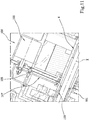
- Figure 1 shows a first embodiment of the propulsion apparatus 1.
- the coaxial rotatable units 9 are defined by at least a first gear wheel 7a and a second gear wheel 7b of the epicyclic gear train 2 and the switching unit 101 comprises an engagement portion 102 rotationally integral in a permanent fashion with the outlet shaft 5.
- the drive shaft 4 is stably connected or constructed integrally with a pinion corresponding to the sun gear 6 of the epicyclic gear train 2 being rotationally constrained and integral.
- the sun gear 6 is engaged permanently with three satellite gears 8 by meshing surfaces 10 shaped to match made on the respective gears, as shown in Figure 2 .
- the number of satellite gears 8 may be different from three.
- the satellite gears 8 are rotationally constrained around respective pins 15 fixed to portions of the containment body "C" of the propulsion apparatus 1 and have two meshing surfaces 10.
- the three satellite gears 8, in a position diametrically opposite that used for coupling with the sun gear 6, are permanently coupled to respective two inner meshing surfaces 10 respectively belonging to the first and second gear wheels 7a and 7b, where the gear wheels have different diameters.
- the coupling between the first and second gear wheels 7a and 7b and satellite gears 8 is permanent but the transmission of the mechanical power only occurs at the meshing surface 10 belonging to the gear wheel 7a or 7b selected from the position of the switching unit 101.
- the switching unit 101 is interposed between the gear wheels 7a and 7b and the output shaft 5, and is used to establish mechanical continuity between the epicyclic gear train 2 and the output shaft 5.
- the gear wheels 7a and 7b are therefore keyed freely on the outlet shaft 5 and rotated about the axis of rotation "X".
- the switching of the transmission ratio occurs with the slipping of the switching unit 101 between a first position (shown in Figure 1 ) corresponding to the first configuration of the propulsion apparatus 1 and a second position (not illustrated in Figure 1 ) corresponding to the second configuration of the propulsion apparatus 1.
- the switching unit 101 and in particular the engagement portion 102, engage selectively the receiving profiles 11 in such a way that in the first position the engagement portion 102 engages the receiving profile 11 of the first gear wheel 7a whilst in the second position of the switching unit 101, the engagement portion 102 engages the receiving profile 11 of the second gear wheel 7b, as shown in detail in Figure 4 .
- the different diameter of the two gear wheels 7a and 7b, at the same speed of rotation of the satellite gears 8, makes it possible to obtain two different tangential speeds of the respective meshing surfaces 10 and consequently two different speeds of rotation of the output shaft 5 as a function of the gear wheel 7a or 7b selected.
- the switching unit 101 is housed at least partly inside the outlet shaft 5 (in turn housed at least partly inside the drive shaft 4) and has an end protruding from the containment body "C" of the propulsion apparatus 1 on which the control actuator 105 is active (not shown in Figure 1 ).
- the propulsion apparatus 1 may comprise a number of gear wheels 7 greater than two.
- the number of positions which can be adopted by the switching unit 101 will be naturally proportional to the number of transmission ratios, as will the number of meshing surfaces 10 present on the at least one satellite gear 8, configured to be permanently coupled with the meshing surfaces 10 of the respective gear wheels 7.
- Figure 6 shows a second embodiment of the propulsion apparatus 1.
- the coaxial rotatable units 9 are defined by at least a first pinion and a second pinion forming a first and a second sun gear 6a and 6b of the epicyclic gear train 2 and wherein the switching unit 101 comprises an engagement portion 102 rotationally integral in a permanent fashion with the drive shaft 4.
- the hollow drive shaft 4 houses at least partly the switching unit 101, which is also hollow.
- the switching unit 101 is rotationally integral with the drive shaft 4 but has the possibility of translating along the axis of rotation "X" thanks to a coupling by grooves.
- the switching unit 101 intercepts and engages selectively and reversibly with one of the two sun gears 6a or 6b.
- the switching unit 101 is movable between a first position in which the respective engagement portion 102 engages the receiving outline 11 of the first sun gear 6a and a second position in which the engagement portion 102 engages the receiving outline 11 of the second sun gear 6b.
- the meshing surfaces 10 of the two sun gears 6a and 6b are permanently coupled to the meshing surfaces 10 of three satellite gears 8.
- the three satellite gears 8 are in effect constrained in rotation to respective pins 15 fixed to a crown wheel 16 free to rotate about the axis of rotation "X" and permanently keyed to the outlet shaft 5, to which it is rotationally constrained and integral.
- the gear wheel 7, on the other hand, is single and connected to a fixed portion of the containment body "C" of the propulsion apparatus 1.
- the satellite gears 8 rotate about the respective pins 15 at a specific speed.
- the rotation of the satellite gears 8 is such as to move in rotation the crown wheel 16 and consequently the outlet shaft 5 to which the crown wheel 16 is constrained.
- the switching unit 101 is at least partly housed in the drive shaft 4, as shown in detail in
- the control actuator 105 which moves the switching unit 101 is preferably of the induction type, as shown in Figure 6 .
- the 105 induction control actuator includes, for example, a solenoid to which explicit reference is made without loss of generality.
- the switching unit 101 is made of ferromagnetic material.
- the solenoid is powered to move the switching unit.
- the switching unit is moved in one direction or in the opposite direction to the first.
- the power supply to the electric motor 3, e.g. the stator of the motor 3, is suspended until the movement of the switching unit 101 is completed.
- the power supply to electric motor 3, e.g. the stator of the motor, is suspended until the power supply to actuator 105 is ended.
- the drive shaft 4 is hollow and has grooves, not illustrated, on its outer surface.
- the switching unit 101 is placed inside motor shaft 4 and engaged with splines so that it is integral to motor shaft 4 in rotation but free to slide axially along it.
- the switching unit 101 comprises the engagement portion 102 configured to be integral, in rotation, with the solar 6a or solar 6b to the motor shaft 4.
- the switching element 101 is axially mobile according to the X axis of rotation.
- control actuator 105 comprises a command fork 107 moved by a 105 solenoid.
- the fork 107 is fixed to a mobile unit 105a made of ferromagnetic material moved by solenoid 105.
- the command fork 107 is constrained to a pin 108.
- the pin 108 is parallel to the X axis and fork 107 slides along it.
- the fork 107 on the opposite side of the solenoid, is engaged with control 101 and moves it in the X direction.
- pin 108 is twisted with respect to the X axis of rotation and fork 107 is rotatable around pin 108.
- satellite gears 8 are rotationally constrained to respective pins 15 fixed to fixed portions of the containment body "C" of the propulsion apparatus 1, whilst the gear wheel 7 is keyed to the outlet shaft 5 being rotationally constrained about the axis of rotation "X".
- gear wheel 7 which move the output shaft 5, transmitting to it mechanical torque and speed of rotation.
- the propulsion apparatus 1 may comprise a number of sun gears 6 greater than two.
- the number of positions which can be adopted by the switching unit 101 will be naturally proportional to the number of transmission ratios, as will the number of meshing surfaces 10 present on the at least one satellite gear 8, configured to be permanently coupled with the meshing surfaces 10 of the respective sun gears 8.
- the invention achieves the preset aims by overcoming the drawbacks of the prior art and providing a propulsion apparatus which is able to operate with a high efficiency in a large operating window whilst maintaining a very low constructional complexity.
- the propulsion apparatus provides various transmission ratios simply by multiplying a single type of coaxial rotatable unit for the number of ratios to be obtained (for example, the gear wheels in the embodiment of Figure 1 and the sun gears in the embodiment of Figure 6 ).
- Another aim achieved is to provide a propulsion apparatus which is able to automate the process for changing the transmission ratio without the need for action by the user.
- the invention also relates to a vehicle fitted with the propulsion apparatus described above, wherein the propulsion apparatus 1 is mounted at the hub of a wheel of the vehicle.
- the vehicle may be a motorcycle with two or three wheels, a tricycle with a motor, an electric bicycle or a pedal assist bike or lightweight four-wheeled vehicles, such as, for example, quadricycles.
- the propulsion apparatus 1, and in particular an end of the outlet shaft 5, are connected to the wheel "R" by an interface to the wheel hub 17 as shown in Figures 8 and 9 .
- the containment body "C” is anchored to the chassis "T" of the vehicle, preferably by bolting.
- the invention achieves the preset aims by providing an vehicle fitted with a propulsion apparatus 1 which is able to operate close to the maximum efficiency in a large operating field without adversely affecting the simplicity of use of the vehicle.
- part of these signals represents the inputs of the user and the driving mode of the user.
- Signals are sent to the control unit coming, for example, from a sensor for measuring the opening of the accelerator, a sensor for measuring the position of the brake lever, a sensor for measuring the vehicle set-up (inertial platform).
- These sensors are able to send signals representing the driving mode of the user, such as, for example, the duration and extent of the accelerations, the duration and extent of the braking, the average and instantaneous speed of the vehicle.
- sensors for measuring the operation of the electric motor 3 which send to the control unit signals representing parameters such as motor revolutions, absorbed current and voltage of the battery.
- the control unit calculates the basic vehicle operating parameters such as the traction torque and the speed of forward movement and checks whether the driving conditions correspond to those defined for changing the transmission ratio.
- control unit removes the power supply to the electric motor 3, zeroing the torque, activates the control actuator switching the position and, after engaging the drive, re-starts the electric motor 3 adjusting its operation to the new transmission ratio.
- this management criterion avoids the use of clutches, whilst maintaining a driving of the vehicle as smooth as possible and without complexities.
- the control unit is configured in such a way as to guarantee a correct and optimised control of the vehicle, and in particular of the change of the transmission ratio.
Landscapes
- Engineering & Computer Science (AREA)
- Mechanical Engineering (AREA)
- General Engineering & Computer Science (AREA)
- Chemical & Material Sciences (AREA)
- Combustion & Propulsion (AREA)
- Transportation (AREA)
- Retarders (AREA)
- Structure Of Transmissions (AREA)
- Friction Gearing (AREA)
Abstract
Description
- This invention relates to a propulsion apparatus and a vehicle fitted with this propulsion apparatus.
- It is extremely important in the transport sector to guarantee the maximum efficiency of the vehicle, and in particular of the propulsion apparatus, in order to reduce consumption and pollution.
- Moreover, it is equally important to guarantee constructional simplicity of the apparatuses of which a vehicle is composed in such a way as to minimise construction and maintenance costs.
- Over recent years, the environmental impact and the development of technology have pushed the transport sector to more actively look towards alternative solutions to traditional fossil fuel engines.
- Amongst the electric vehicles typically used, there is, for example, the use of drive wheels mounted on lightweight vehicles, typically with two wheels, such as mopeds or electric bicycles and pedal assist bikes.
- The expression "drive wheel" means, in this description, a propulsion apparatus comprising an electric motor coupled to an epicyclic gear train for reducing or multiplying motor revolutions, housed inside the wheel rim of the vehicle.
- This solution has several advantages such as, for example, the simplification of layout, constructional compactness and the performances which significantly reduce the production costs and, consequently, facilitate entry on the market.
- However, in order to fully exploit the potential of the electric motors it is necessary to take into account the characteristic operating curve and the context in which they are used.
- In fact, the efficiency of an electric motor depends mainly on parameters such as the rotation speed and the delivered torque. In particular, the electric motor operates at low efficiency values for low rotation speeds and for low torque values delivered.
- In other words, the electric motor operates at maximum efficiency in a small operating range for optimum values of these parameters.
- If we consider, for example, the highway application, it is evident how the electric motor, mounted, for example, on a aerostatic, will work, for most of the time, far from these optimum values.
- For this purpose, the introduction of at least a second transmission ratio is known for widening the operating field in which the motor operates at high efficiency.
- However, this solution has made the propulsion apparatus, and in particular an epicyclic gear train contained therein, more complex, increasing the number of components and, consequently, the production cost.
- Moreover, the transmission ratio, in these solutions, is typically obtained by means of manually operated clutches which make its by the user more complicated and complex.
- For example, considering a moped, one of the main advantages is precisely to have a single transmission ratio without the presence of gears. A strongly felt need is therefore to develop propulsion apparatuses, and in particular drive wheel, which are able to operate in a very efficient manner without losing the structural simplicity which limits the construction costs.
- The aim of the invention is to satisfy the above-mentioned needs.
- In particular, the aim of the invention is to provide a propulsion apparatus and a vehicle fitted with the propulsion apparatus which operate in an efficient manner, in particular operating in a large operating window.
- A further aim of the invention is to provide a propulsion apparatus and a vehicle fitted with this propulsion system characterised by a greater constructional simplicity.
- A further aim of the invention is to provide a propulsion apparatus and a vehicle fitted with this propulsion system which is able to make the driving simple and not complicated.
- The technical purpose indicated and the aims specified are substantially achieved by a propulsion apparatus and a vehicle fitted with the propulsion system which is able to operate with at least two possible transmission ratios.
- Further features and advantages of the invention are more apparent in the non-limiting description which follows of a preferred embodiment of a propulsion apparatus and a vehicle fitted with the propulsion apparatus. The description is set out below with reference to the accompanying drawings which are provided solely for purposes of illustration without restricting the scope of the invention and in which:
-
Figure 1 is a side view cross-section of an embodiment of the propulsion apparatus according to the description; -
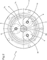
Figure 2 is a transversal cross-section of the propulsion apparatus ofFigure 1 according to the description; -
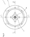
Figure 3 is a rear view of the propulsion apparatus ofFigure 1 according to the description; -
Figure 4 is a detail of the side view cross-section of the embodiment of the propulsion apparatus ofFigure 1 according to the description; -
Figure 5 is a top view cross-section of the propulsion apparatus ofFigure 1 according to the description; -
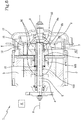
Figure 6 is a side view cross-section of a further embodiment of the propulsion apparatus according to the description; -
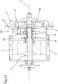
Figure 7 is a detail of the side view cross-section of the embodiment of the propulsion apparatus ofFigure 6 according to the description; -
Figure 8 is a side view of a detail of a vehicle fitted with an embodiment of a propulsion apparatus according to the description; -
Figure 9 is a rear view cross-section of vehicle fitted with an embodiment of a propulsion apparatus according to the description. -
Figure 10 shows a form of realization of a propulsion apparatus in accordance with this description, in a schematic section view; -
Figure 11 shows a detail of a form of realization of a propulsion apparatus in accordance with this description, in a schematic section view. - With reference to the accompanying drawings, the
numeral 1 denotes in its entirety a propulsion apparatus according to the invention. - Mainly, the
propulsion apparatus 1 comprises anepicyclic gear train 2, anelectric motor 3 withrespective drive shaft 4, anoutput shaft 5 and anactuation system 100. - The
propulsion apparatus 1 preferably comprises a containment body "C" in which are housed, at least partly, theepicyclic gear train 2, theelectric motor 3, thedrive shaft 4 and theoutput shaft 5. - The
electric motor 3 transforms the input electrical power, provided preferably by a battery (not illustrated in the drawings), into mechanical power made available to thedrive shaft 4 which is rotationally constrained about an axis of rotation "X". - The
drive shaft 4 is coupled to theepicyclic gear train 2, which is interposed between thedrive shaft 4 and theoutput shaft 5. - The
epicyclic gear train 2 comprises at least onesun gear 6, at least one gear wheel 7 and at least onesatellite gear 8, interposed between at least onesun gear 6 and at least one gear wheel 7. - The
epicyclic gear train 2 is configured to adopt at least two different configurations corresponding to different transmission ratios between thedrive shaft 4 and theoutput shaft 5. - In other words, the
epicyclic gear train 2 makes it possible to obtain at least two different ratios between the speed of rotation of thedrive shaft 4 and the speed of rotation of theoutput shaft 5, substantially transferring the same mechanical power. - The
epicyclic gear train 2 can switch between these at least two configurations by the action of theactuation system 100. - In particular, the
actuation system 100 comprises aswitching unit 101, slidable along the axis of rotation "X" of thedrive shaft 4 between a first and at least a second position corresponding, respectively, to the at least a first and a second configuration of theepicyclic gear train 2. Still more specifically, theswitching unit 101 comprises anengagement portion 102 configured for engaging respective portions of theepicyclic gear train 2 as a function of the at least a first and a second position in which theswitching unit 101 is located. - In other words, depending on the position adopted by the
switching unit 101, it can be selectively engaged in a reversible fashion with coaxialrotatable units 9 forming part of theepicyclic gear train 2. - The
epicyclic gear train 2 comprises coaxialrotatable units 9 which, selectively engaged by theactuation system 100, allow theepicyclic gear train 2 to vary configuration and corresponding transmission ratio between thedrive shaft 4 and theoutput shaft 5. - The coaxial
rotatable units 9 are adjacent to each other and have meshingsurfaces 10 having different diameters for making the different transmission ratios. - In other words, at the same angular speed transmitted by the
drive shaft 4, the selection of the coaxialrotatable units 9 allows the speed of theoutlet shaft 5 to be varied because the coaxialrotatable units 9 have different tangential speeds due to the fact that they have different diameters. - In this way, the
epicyclic gear train 2 modifies the ratio between the rotation revolutions of thedrive shaft 4 and the rotation revolutions of theoutlet shaft 5 to which theepicyclic gear train 2 is interposed. - In particular, the
switching unit 101 is interposed between the coaxialrotatable units 9 and one between thedrive shaft 4 and theoutlet shaft 5, as a function of the embodiment used, as described below. - The coupling between the
switching unit 101 and the coaxialrotatable units 9 occurs by means of theengagement portion 102, included in theswitching unit 101, and acorresponding receiving outline 11, made on each of the coaxialrotatable units 9 and shaped to match theengagement portion 102. - In particular, the coupling is such as to constrain the rotation of the
engagement portion 102 and the coaxialrotatable element 9 selected, making them integral. - The coupling occurs by moving the
switching unit 101 along the axis of rotation "X" between the respective positions until engaging the selected coaxialrotatable unit 9. - In fact, the
switching unit 101 has aguide portion 103, integral with theengagement portion 102, housed at least partly inside thedrive shaft 4 or theoutlet shaft 5. - The coupling between the
switching unit 101 and one between thedrive shaft 4 and theoutlet shaft 5 is such as to constrain them in rotation allowing the sliding in a longitudinal direction thanks to the presence of grooves (not shown in the drawings). - In other words, once engaged, the
switching unit 101 is rotationally constrained both to the selected coaxialrotatable unit 9 and to one between thedrive shaft 4 and theoutput shaft 5, thus establishing mechanical continuity between these elements. - The
guide portion 103 and theengagement portion 102 may be made in an integral fashion (as a single body) or theengagement portion 102 may be applied stably to theguide portion 103, and in particular to a relative end coming out from thedrive shaft 4 or from theoutlet shaft 5 to which it is coupled, by means of, for example, keying, screwing, fastening with ring nut. - The
engagement portion 102 is axially outside thedrive shaft 4 or theoutlet shaft 5 to which it is coupled in such a way as to be able to selectively engage the receiving portion of the coaxialrotatable units 9 in which it is, after engaging, at least partly housed. - With regard to the coaxial
rotatable units 9, theirmeshing surfaces 10 are engaged, preferably in a permanent fashion, withrespective meshing surfaces 10 of the at least onesatellite gear 8. - In effect, the at least one
satellite gear 8 has a plurality of meshingsurfaces 10 having different diameters. The number of meshingsurfaces 10 of the at least onesatellite gear 8 corresponds to the number of coaxialrotatable units 9 and, therefore, to the number of transmission ratios provided by theepicyclic gear train 2. - In particular, the
meshing surfaces 10 of thesatellite gear 8 are rotationally integral with each other and preferably thesatellite gear 8 is made of a monolithic body. - In order to improve the stability of the positions adopted by the
switching unit 101 relative to the coaxialrotatable units 9, thepropulsion apparatus 1 has stabilisingmeans 12 configured to stabilise the axial position of theswitching unit 101 at the at least a first and a second position. - Preferably, the stabilising means 12, made in a portion of the containment body "C", comprise one or
more stop members 13 kept radially pressed against an outer surface of theswitching unit 101 and engageable inrespective sockets 104 of theswitching unit 101. - As shown in detail in
Figure 5 thestop elements 104 are preferably associated withsprings 14, housed in respective seats, which push them preferably in a radial direction towards the axis of rotation "X". - The
sockets 104 are positioned in such a way as to engage thestop elements 13 when theswitching unit 101 reaches the at least a first and a second position. - Preferably, the
sockets 104 have ramps positioned specularly and configured to radially move thestop elements 13, overcoming the elastic force of thesprings 14, during the translation of theswitching unit 101 between the at least two positions. - Advantageously, thanks to the stabilising means 12, the
switching unit 101 adopts a stable axial position, considerably reducing slipping due to the vibrations which occur in the normal operation of thepropulsion apparatus 1. - According to an embodiment the
switching unit 101, and in general the electro-mechanical actuator, are positioned partly outside the containment body "C" of thepropulsion apparatus 1 to allow a switching action activated from the outside of the containment body "C". - The
actuation system 100 is, in effect, controlled by a control unit "U", configured to operate automatically as a function of at least one operating parameter of thepropulsion apparatus 1 calculated by the control unit "U" starting from measurements carried out by respective sensors, wherein the measurements are continuously recorded by the control unit "U". Based on these data and a mapping which takes into account the characteristics of the engine, the control unit "U" calculates the fundamental parameters and checks whether the conditions correspond to those defined for changing the transmission ratio. - The parameters are selected between: motor revolutions, absorbed current, battery voltage.
- In this way, the control unit "U" sends the transmission ratio change signal to the
actuation system 100. - According to a preferred embodiment, the
actuation system 100 comprises acontrol actuator 105 by which theswitching element 101 moves translationally between the at least two positions, varying in effect the configuration, and therefore the transmission ratio, of thepropulsion apparatus 1. - The
control actuator 105 may be formed inside or outside the containment body "C" of thepropulsion apparatus 1. - The
control actuator 105 may be selected, for example, between induction type actuators and pneumatic type actuators. - Different embodiments of the
propulsion apparatus 1 are discussed below. -
Figure 1 shows a first embodiment of thepropulsion apparatus 1. - According to this embodiment, the coaxial
rotatable units 9 are defined by at least afirst gear wheel 7a and asecond gear wheel 7b of theepicyclic gear train 2 and theswitching unit 101 comprises anengagement portion 102 rotationally integral in a permanent fashion with theoutlet shaft 5. - In other words, the
drive shaft 4 is stably connected or constructed integrally with a pinion corresponding to thesun gear 6 of theepicyclic gear train 2 being rotationally constrained and integral. - The
sun gear 6 is engaged permanently with threesatellite gears 8 by meshingsurfaces 10 shaped to match made on the respective gears, as shown inFigure 2 . - According to other embodiments, the number of satellite gears 8 may be different from three.
- The satellite gears 8 are rotationally constrained around
respective pins 15 fixed to portions of the containment body "C" of thepropulsion apparatus 1 and have two meshing surfaces 10. - The three
satellite gears 8, in a position diametrically opposite that used for coupling with thesun gear 6, are permanently coupled to respective two inner meshing surfaces 10 respectively belonging to the first andsecond gear wheels - The coupling between the first and
second gear wheels surface 10 belonging to thegear wheel switching unit 101. - In fact, in this configuration, the
switching unit 101 is interposed between thegear wheels output shaft 5, and is used to establish mechanical continuity between theepicyclic gear train 2 and theoutput shaft 5. - According to this embodiment, the
gear wheels outlet shaft 5 and rotated about the axis of rotation "X". The switching of the transmission ratio occurs with the slipping of theswitching unit 101 between a first position (shown inFigure 1 ) corresponding to the first configuration of thepropulsion apparatus 1 and a second position (not illustrated inFigure 1 ) corresponding to the second configuration of thepropulsion apparatus 1. - In these two positions, the
switching unit 101, and in particular theengagement portion 102, engage selectively the receivingprofiles 11 in such a way that in the first position theengagement portion 102 engages the receivingprofile 11 of thefirst gear wheel 7a whilst in the second position of theswitching unit 101, theengagement portion 102 engages the receivingprofile 11 of thesecond gear wheel 7b, as shown in detail inFigure 4 . - The different diameter of the two
gear wheels output shaft 5 as a function of thegear wheel - The
switching unit 101 is housed at least partly inside the outlet shaft 5 (in turn housed at least partly inside the drive shaft 4) and has an end protruding from the containment body "C" of thepropulsion apparatus 1 on which thecontrol actuator 105 is active (not shown inFigure 1 ). According to other embodiments not illustrated, thepropulsion apparatus 1 may comprise a number of gear wheels 7 greater than two. - This translates into an increase in the transmission ratios of the
propulsion apparatus 1. - The number of positions which can be adopted by the
switching unit 101 will be naturally proportional to the number of transmission ratios, as will the number of meshing surfaces 10 present on the at least onesatellite gear 8, configured to be permanently coupled with the meshing surfaces 10 of the respective gear wheels 7. -
Figure 6 shows a second embodiment of thepropulsion apparatus 1. - In this embodiment, the coaxial
rotatable units 9 are defined by at least a first pinion and a second pinion forming a first and asecond sun gear epicyclic gear train 2 and wherein theswitching unit 101 comprises anengagement portion 102 rotationally integral in a permanent fashion with thedrive shaft 4. - In other words, the
hollow drive shaft 4 houses at least partly theswitching unit 101, which is also hollow. - The
switching unit 101 is rotationally integral with thedrive shaft 4 but has the possibility of translating along the axis of rotation "X" thanks to a coupling by grooves. - In the various positions adopted, the
switching unit 101 intercepts and engages selectively and reversibly with one of the twosun gears switching unit 101 is movable between a first position in which therespective engagement portion 102 engages the receivingoutline 11 of thefirst sun gear 6a and a second position in which theengagement portion 102 engages the receivingoutline 11 of thesecond sun gear 6b. - Since they have different diameters they will have a meshing
surface 10 which at the same angular speed will have different tangential speeds. - The meshing surfaces 10 of the two
sun gears - Depending on the
sun gear - The three
satellite gears 8 are in effect constrained in rotation torespective pins 15 fixed to acrown wheel 16 free to rotate about the axis of rotation "X" and permanently keyed to theoutlet shaft 5, to which it is rotationally constrained and integral. - The gear wheel 7, on the other hand, is single and connected to a fixed portion of the containment body "C" of the
propulsion apparatus 1. - In this way, as a function of the selected
sun gear respective pins 15 at a specific speed. The rotation of the satellite gears 8 is such as to move in rotation thecrown wheel 16 and consequently theoutlet shaft 5 to which thecrown wheel 16 is constrained. - According to this embodiment, as already mentioned, the
switching unit 101 is at least partly housed in thedrive shaft 4, as shown in detail in -
Figure 7 . - The
control actuator 105 which moves theswitching unit 101 is preferably of the induction type, as shown inFigure 6 . - The 105 induction control actuator includes, for example, a solenoid to which explicit reference is made without loss of generality.
- The
switching unit 101 is made of ferromagnetic material. - In use, the solenoid is powered to move the switching unit.
- Depending on the direction of the current, the switching unit is moved in one direction or in the opposite direction to the first.
- When the
control actuator 105 is powered, the power supply to theelectric motor 3 is suspended. - Preferably, the power supply to the
electric motor 3, e.g. the stator of themotor 3, is suspended until the movement of theswitching unit 101 is completed. - Preferably, the power supply to
electric motor 3, e.g. the stator of the motor, is suspended until the power supply toactuator 105 is ended. - In one embodiment, illustrated for example in
Figures 10 and11 , thedrive shaft 4 is hollow and has grooves, not illustrated, on its outer surface. - The
switching unit 101 is placed insidemotor shaft 4 and engaged with splines so that it is integral tomotor shaft 4 in rotation but free to slide axially along it. - The
switching unit 101 comprises theengagement portion 102 configured to be integral, in rotation, with the solar 6a or solar 6b to themotor shaft 4. The switchingelement 101 is axially mobile according to the X axis of rotation. - In the example illustrated,
control actuator 105 comprises acommand fork 107 moved by a 105 solenoid. - The
fork 107 is fixed to a mobile unit 105a made of ferromagnetic material moved bysolenoid 105. - The
command fork 107 is constrained to apin 108. - The
pin 108 is parallel to the X axis and fork 107 slides along it. - The
fork 107, on the opposite side of the solenoid, is engaged withcontrol 101 and moves it in the X direction. - In an embodiment,
pin 108 is twisted with respect to the X axis of rotation andfork 107 is rotatable aroundpin 108. - In an embodiment, not illustrated the satellite gears 8 are rotationally constrained to
respective pins 15 fixed to fixed portions of the containment body "C" of thepropulsion apparatus 1, whilst the gear wheel 7 is keyed to theoutlet shaft 5 being rotationally constrained about the axis of rotation "X". - According to this embodiment it is the gear wheel 7 which move the
output shaft 5, transmitting to it mechanical torque and speed of rotation. - According to other embodiments not illustrated, the
propulsion apparatus 1 may comprise a number of sun gears 6 greater than two. - This translates into an increase in the transmission ratios of the
propulsion apparatus 1. - The number of positions which can be adopted by the
switching unit 101 will be naturally proportional to the number of transmission ratios, as will the number of meshing surfaces 10 present on the at least onesatellite gear 8, configured to be permanently coupled with the meshing surfaces 10 of the respective sun gears 8. - The invention achieves the preset aims by overcoming the drawbacks of the prior art and providing a propulsion apparatus which is able to operate with a high efficiency in a large operating window whilst maintaining a very low constructional complexity.
- In fact, the propulsion apparatus provides various transmission ratios simply by multiplying a single type of coaxial rotatable unit for the number of ratios to be obtained (for example, the gear wheels in the embodiment of
Figure 1 and the sun gears in the embodiment ofFigure 6 ). - Another aim achieved is to provide a propulsion apparatus which is able to automate the process for changing the transmission ratio without the need for action by the user.
- The user will not therefore be involved in the action for changing the transmission ratio, thus simplifying the use of the apparatus.
- The invention also relates to a vehicle fitted with the propulsion apparatus described above, wherein the
propulsion apparatus 1 is mounted at the hub of a wheel of the vehicle. - The vehicle may be a motorcycle with two or three wheels, a tricycle with a motor, an electric bicycle or a pedal assist bike or lightweight four-wheeled vehicles, such as, for example, quadricycles.
- The
propulsion apparatus 1, and in particular an end of theoutlet shaft 5, are connected to the wheel "R" by an interface to thewheel hub 17 as shown inFigures 8 and9 . - The containment body "C" is anchored to the chassis "T" of the vehicle, preferably by bolting.
- Advantageously, the invention achieves the preset aims by providing an vehicle fitted with a
propulsion apparatus 1 which is able to operate close to the maximum efficiency in a large operating field without adversely affecting the simplicity of use of the vehicle. - In effect, there is a plurality of sensors on the vehicle designed to measure a respective plurality of signals representing the operation of the vehicle.
- In particular, part of these signals represents the inputs of the user and the driving mode of the user. Signals are sent to the control unit coming, for example, from a sensor for measuring the opening of the accelerator, a sensor for measuring the position of the brake lever, a sensor for measuring the vehicle set-up (inertial platform).
- These sensors are able to send signals representing the driving mode of the user, such as, for example, the duration and extent of the accelerations, the duration and extent of the braking, the average and instantaneous speed of the vehicle.
- Preferably, there are sensors for measuring the operation of the
electric motor 3, which send to the control unit signals representing parameters such as motor revolutions, absorbed current and voltage of the battery. - Based on this data, which is continuously recorded, and a mapping which takes into account the intrinsic characteristics of the engine, the control unit calculates the basic vehicle operating parameters such as the traction torque and the speed of forward movement and checks whether the driving conditions correspond to those defined for changing the transmission ratio.
- If the driving conditions correspond to those defined for changing the transmission ratio, the control unit removes the power supply to the
electric motor 3, zeroing the torque, activates the control actuator switching the position and, after engaging the drive, re-starts theelectric motor 3 adjusting its operation to the new transmission ratio. - Advantageously, this management criterion avoids the use of clutches, whilst maintaining a driving of the vehicle as smooth as possible and without complexities.
- The control unit is configured in such a way as to guarantee a correct and optimised control of the vehicle, and in particular of the change of the transmission ratio.
Claims (17)
- A propulsion apparatus (1) comprising:- an epicyclic gear train (2) comprising at least one sun gear (6), at least one gear wheel (7) and at least one satellite gear (8), interposed between said at least one sun gear (6) and said at least one gear wheel (7);- an electric motor (3) comprising a drive shaft (4) connected to said at least one sun gear (6) for providing power to said epicyclic gear train (2);- an output shaft (5), coupled to said epicyclic gear train (2) for actuating a mechanical load;wherein said epicyclic gear train (2) is configured to adopt at least two different configurations corresponding to different transmission ratios between the drive shaft (4) and the output shaft (5), and
wherein said apparatus (1) comprises an actuation system (100), acting on said epicyclic gear train (2) and configured in such a way as to switch said epicyclic gear train (2) between said at least two configurations. - The apparatus (1) according to claim 1, wherein the actuation system (100) comprises a switching unit (101) slidable along the axis of rotation (X) of said drive shaft (4) between at least a first and a second position corresponding, respectively, to said at least a first and second configuration of the epicyclic gear train (2).
- The apparatus according to claim 2, wherein said actuation system (100) comprises a control actuator (105) associated with said switching unit (101) for moving it between said first and said second position corresponding, respectively, to said at least one first and second configuration of the epicyclic gear train (2).
- The apparatus according to any one of the preceding claims, wherein the actuation system (100) comprises a switching unit (101) movable between at least a first and a second position corresponding, respectively, to said at least a first and second configuration of the epicyclic gear train (2), said switching unit (101) comprising an engagement portion (102) configured to engage respective portions of said epicyclic gear train (2) as a function of said at least a first and second position.
- The apparatus (1) according to claim 3, comprising a control unit (U) configured for controlling said control actuator (105), as a function of at least one operating parameter of the propulsion apparatus (1) measured by a respective sensor, preferably said at least one operating parameter being selected from: motor revolutions, absorbed current, battery voltage.
- The apparatus (1) according to any one of claims 2 to 5, wherein said switching unit (101) is selectively engageable with coaxial rotatable elements (9), adjacent to each other, of said epicyclic gear train (2), said coaxial rotatable members (9) having meshing surfaces (10) having different diameters for making said different transmission ratios.
- The apparatus (1) according to claim 4 or 6, wherein said engagement portion (102) is rotationally integral in a permanent fashion with one or other of said drive shaft (4) and output shaft (5) and can be engaged, selectively and reversibly, with one of said coaxial rotatable elements (9), in particular by means of a shape and/or toothed coupling with a corresponding receiving shape (11) made on each of said coaxial rotatable elements (9).
- The apparatus (1) according to claim 4 or 6, wherein said engagement portion (102) is coupled in an axially slidable manner with said drive shaft (4) or output shaft (5), in particular by grooved coupling, preferably said drive shaft (4) or output shaft (5) being hollow and said switching unit (101) comprising a guide portion (103), integral with the engagement portion (102) and housed inside said drive shaft (4) or output shaft (5), said engagement portion (102) being axially outside said drive shaft (4) or output shaft (5) and configured for the direct engagement with the coaxial rotatable elements (9).
- The apparatus (1) according to any one of claims 6 to 8, wherein said at least one satellite gear (8) has a plurality of meshing surfaces (10) having different diameters and engaged, preferably permanently, with said meshing surfaces (10) of the coaxial rotatable elements (9), said meshing surfaces (10) of the satellite gear (8) being rotationally integral with each other and preferably said at least one satellite gear (8) being made in a monolithic body.
- The apparatus (1) according to any one of claims 6 to 9, wherein said coaxial rotatable elements (9) are defined by at least a first crown (7a) and a second crown (7b) of said epicyclic gear train (2) and wherein said switching unit (101) comprises an engagement portion (102) rotationally integral in a permanent fashion with said output shaft (5), preferably said epicyclic gear train (2) comprising a single sun gear (6) integral with said drive shaft (4), in particular engaged permanently with one of the engagement surfaces (10) of said at least one satellite gear (8).
- The apparatus (1) according to any one of claims 6 to 9, wherein said coaxial rotatable elements (9) are defined by at least a first pinion and a second pinion forming solar gears (6a and 6b) of said epicyclic gear train (2) and wherein said switching unit (101) comprises an engagement portion (102) rotationally integral in a permanent fashion with said drive shaft (4), preferably said epicyclic gear train (2) comprising a single gear wheel (7), in particular said gear wheel (7) being engaged permanently with one of the engagement surfaces (10) of said at least one satellite gear (8).
- The apparatus (1) according to claim 11, wherein the output shaft (5) is integral with a planet element (16) rotatable about the axis of rotation (X) of the drive shaft (4) and carrying said at least one satellite gear (8), and wherein said gear wheel (7) is fixed.
- The apparatus (1) according to claim 11, wherein said output shaft (5) is integral said the gear wheel (7) and wherein said epicyclic gear train (2) comprises a fixed plant element (16), positioned about the axis of rotation (X) of the drive shaft (4) and carrying said at least one satellite gear (8).
- The apparatus (1) according to any one of claims 2 to 13, wherein said switching unit (101) has stabilising means (12) configured to stabilise the axial position of the switching unit (101) at said at least a first and a second position, preferably said stabilising means (12) comprising one or more stop members (13) kept in radial thrust against an outer surface of the switching unit (101) and engageable in respective sockets (104) of the switching unit (101), located in a position such as to house said stop members (13) when the switching unit (101) reaches said least a first and a second position.
- The apparatus (1) according to any one of the preceding claims, comprising a containment body (C) in which are housed said electric motor (3), said epicyclic gear train (2) and, at least partly, said actuation system (100).
- The apparatus according to any one of claims 2 to 14 and claim 15, wherein said switching unit (101) is partly protruding from said containment body (C) to allow a switching action activated from the outside of said containment body (C).
- A vehicle fitted with a propulsion apparatus (1) according to any one of the preceding claims, wherein the propulsion apparatus (1) is mounted at the hub of a wheel (R) of said vehicle.
Applications Claiming Priority (1)
| Application Number | Priority Date | Filing Date | Title |
|---|---|---|---|
| IT102019000020144A IT201900020144A1 (en) | 2019-10-31 | 2019-10-31 | WHEEL MOTOR WITH PLANETARY GEARBOX. |
Publications (3)
| Publication Number | Publication Date |
|---|---|
| EP3815947A1 true EP3815947A1 (en) | 2021-05-05 |
| EP3815947B1 EP3815947B1 (en) | 2023-09-13 |
| EP3815947C0 EP3815947C0 (en) | 2023-09-13 |
Family
ID=69743855
Family Applications (1)
| Application Number | Title | Priority Date | Filing Date |
|---|---|---|---|
| EP20204026.7A Active EP3815947B1 (en) | 2019-10-31 | 2020-10-27 | Drive wheel with epicyclic gear |
Country Status (3)
| Country | Link |
|---|---|
| EP (1) | EP3815947B1 (en) |
| CN (1) | CN112747082A (en) |
| IT (1) | IT201900020144A1 (en) |
Citations (3)
| Publication number | Priority date | Publication date | Assignee | Title |
|---|---|---|---|---|
| CA853439A (en) * | 1970-10-13 | C. Wickman Axel | Epicyclic change-speed gearing | |
| GB1248494A (en) * | 1968-11-27 | 1971-10-06 | Dso Balkancar | An electric motor-wheel |
| EP2855249A1 (en) * | 2012-05-31 | 2015-04-08 | Robert Bosch GmbH | Planetary gear transmission and electric vehicle |
Family Cites Families (10)
| Publication number | Priority date | Publication date | Assignee | Title |
|---|---|---|---|---|
| GB697911A (en) * | 1949-07-28 | 1953-09-30 | Pol Ravigneaux | Improvements in or relating to epicyclic change-speed gears |
| GB768342A (en) * | 1951-06-04 | 1957-02-13 | Sturmey Archer Gears Ltd | Improvements in or relating to epicyclic change speed gears |
| FR2840043B1 (en) * | 2002-05-23 | 2004-12-03 | Antonov Automotive Europ | TRANSMISSION DEVICE, FOR LAND VEHICLE, ESPECIALLY CAR |
| EP2416033B1 (en) * | 2009-03-31 | 2018-09-19 | Honda Motor Co., Ltd. | Drive device and vehicle with same |
| DE102013110334B4 (en) * | 2013-09-19 | 2019-01-03 | Alber Gmbh | Drive wheel for a small vehicle, in particular wheelchair |
| GB201504469D0 (en) * | 2015-03-17 | 2015-04-29 | Qinetiq Ltd | Gearing assembly |
| CN106641115A (en) * | 2017-02-13 | 2017-05-10 | 西北工业大学 | Coaxial contrarotating speed reducer |
| US10500941B2 (en) * | 2017-08-18 | 2019-12-10 | Arvinmeritor Technology, Llc | Axle assembly having an electric motor module and a shift mechanism |
| GB201800890D0 (en) * | 2018-01-19 | 2018-03-07 | Qinetiq Ltd | Gearing assemblies and apparatus |
| CN109291785A (en) * | 2018-11-22 | 2019-02-01 | 武汉思得汽车科技有限公司 | A kind of motor assembly system of built-in retarder |
-
2019
- 2019-10-31 IT IT102019000020144A patent/IT201900020144A1/en unknown
-
2020
- 2020-10-21 CN CN202011134890.7A patent/CN112747082A/en active Pending
- 2020-10-27 EP EP20204026.7A patent/EP3815947B1/en active Active
Patent Citations (3)
| Publication number | Priority date | Publication date | Assignee | Title |
|---|---|---|---|---|
| CA853439A (en) * | 1970-10-13 | C. Wickman Axel | Epicyclic change-speed gearing | |
| GB1248494A (en) * | 1968-11-27 | 1971-10-06 | Dso Balkancar | An electric motor-wheel |
| EP2855249A1 (en) * | 2012-05-31 | 2015-04-08 | Robert Bosch GmbH | Planetary gear transmission and electric vehicle |
Also Published As
| Publication number | Publication date |
|---|---|
| EP3815947B1 (en) | 2023-09-13 |
| EP3815947C0 (en) | 2023-09-13 |
| IT201900020144A1 (en) | 2021-05-01 |
| CN112747082A (en) | 2021-05-04 |
Similar Documents
| Publication | Publication Date | Title |
|---|---|---|
| US9366321B2 (en) | Planetary gear transmission and electric vehicle | |
| EP2526010B1 (en) | Motor having integrated torque sensor | |
| CN107020952B (en) | Transfer case for four-wheel drive vehicles | |
| EP2755887B1 (en) | Bicyle having a hub incorporating a variable ratio transmission system | |
| EP2218634B1 (en) | Bicycle transmission system | |
| CN108474233B (en) | Human body hybrid system for vehicle or mobile device using magnetorheological fluid clutch apparatus | |
| US8968134B2 (en) | Power transmission apparatus using a planetary gear | |
| KR101029637B1 (en) | Electronic 2-speed transfer case | |
| CN103974847A (en) | Electric drive system for a battery-powered light vehicle | |
| CN104507726A (en) | Drive arrangement for a vehicle, vehicle including such a drive arrangement and method for controlling such a drive arrangement | |
| CN105270562A (en) | Side-hanging pendulum type self-adaptive automatic transmission driving assembly for electric motorcycle | |
| CN101323252A (en) | Cone Disc Clutch Cam Adaptive Automatic Transmission Hub | |
| EP3815947B1 (en) | Drive wheel with epicyclic gear | |
| KR101023431B1 (en) | Variable direct drive transmission | |
| CN201971124U (en) | Bicycle middle-axle planet gear speed-changing device | |
| TWI828787B (en) | Transmission unit for motor vehicles with reverse drive and motor vehicle comprising the transmission unit | |
| CN101376420B (en) | Energy-saving sliding adaptive automatic transmission hub | |
| CN206900580U (en) | A kind of motor tricycle and its transmission system | |
| KR101217133B1 (en) | Bearing breakaway prevention device for combination gear of transmission device for motor vehicle | |
| JP2015158239A (en) | Transmission and electric vehicle equipped therewith | |
| CN212055806U (en) | Speed change structure of electric vehicle | |
| JP2522642B2 (en) | Reverse device for motorcycles, etc. | |
| EP2480447B1 (en) | Automatic motorised derailleur | |
| KR20240167224A (en) | Single shaft drive for electric mobility | |
| KR20120021969A (en) | Transmission device for three or four wheels motor vehicle and three or four wheels vehicle with the same |
Legal Events
| Date | Code | Title | Description |
|---|---|---|---|
| PUAI | Public reference made under article 153(3) epc to a published international application that has entered the european phase |
Free format text: ORIGINAL CODE: 0009012 |
|
| STAA | Information on the status of an ep patent application or granted ep patent |
Free format text: STATUS: THE APPLICATION HAS BEEN PUBLISHED |
|
| AK | Designated contracting states |
Kind code of ref document: A1 Designated state(s): AL AT BE BG CH CY CZ DE DK EE ES FI FR GB GR HR HU IE IS IT LI LT LU LV MC MK MT NL NO PL PT RO RS SE SI SK SM TR |
|
| STAA | Information on the status of an ep patent application or granted ep patent |
Free format text: STATUS: REQUEST FOR EXAMINATION WAS MADE |
|
| 17P | Request for examination filed |
Effective date: 20211103 |
|
| RBV | Designated contracting states (corrected) |
Designated state(s): AL AT BE BG CH CY CZ DE DK EE ES FI FR GB GR HR HU IE IS IT LI LT LU LV MC MK MT NL NO PL PT RO RS SE SI SK SM TR |
|
| RIC1 | Information provided on ipc code assigned before grant |
Ipc: F16H 3/66 19680901ALI20230110BHEP Ipc: F16H 3/00 19680901ALI20230110BHEP Ipc: B60K 7/00 19680901AFI20230110BHEP |
|
| GRAP | Despatch of communication of intention to grant a patent |
Free format text: ORIGINAL CODE: EPIDOSNIGR1 |
|
| STAA | Information on the status of an ep patent application or granted ep patent |
Free format text: STATUS: GRANT OF PATENT IS INTENDED |
|
| INTG | Intention to grant announced |
Effective date: 20230328 |
|
| GRAS | Grant fee paid |
Free format text: ORIGINAL CODE: EPIDOSNIGR3 |
|
| GRAA | (expected) grant |
Free format text: ORIGINAL CODE: 0009210 |
|
| STAA | Information on the status of an ep patent application or granted ep patent |
Free format text: STATUS: THE PATENT HAS BEEN GRANTED |
|
| AK | Designated contracting states |
Kind code of ref document: B1 Designated state(s): AL AT BE BG CH CY CZ DE DK EE ES FI FR GB GR HR HU IE IS IT LI LT LU LV MC MK MT NL NO PL PT RO RS SE SI SK SM TR |
|
| REG | Reference to a national code |
Ref country code: CH Ref legal event code: EP |
|
| REG | Reference to a national code |
Ref country code: DE Ref legal event code: R096 Ref document number: 602020017546 Country of ref document: DE |
|
| REG | Reference to a national code |
Ref country code: IE Ref legal event code: FG4D |
|
| U01 | Request for unitary effect filed |
Effective date: 20231011 |
|
| U07 | Unitary effect registered |
Designated state(s): AT BE BG DE DK EE FI FR IT LT LU LV MT NL PT SE SI Effective date: 20231019 |
|
| U20 | Renewal fee for the european patent with unitary effect paid |
Year of fee payment: 4 Effective date: 20231027 |
|
| PG25 | Lapsed in a contracting state [announced via postgrant information from national office to epo] |
Ref country code: GR Free format text: LAPSE BECAUSE OF FAILURE TO SUBMIT A TRANSLATION OF THE DESCRIPTION OR TO PAY THE FEE WITHIN THE PRESCRIBED TIME-LIMIT Effective date: 20231214 |
|
| PG25 | Lapsed in a contracting state [announced via postgrant information from national office to epo] |
Ref country code: RS Free format text: LAPSE BECAUSE OF FAILURE TO SUBMIT A TRANSLATION OF THE DESCRIPTION OR TO PAY THE FEE WITHIN THE PRESCRIBED TIME-LIMIT Effective date: 20230913 Ref country code: NO Free format text: LAPSE BECAUSE OF FAILURE TO SUBMIT A TRANSLATION OF THE DESCRIPTION OR TO PAY THE FEE WITHIN THE PRESCRIBED TIME-LIMIT Effective date: 20231213 Ref country code: HR Free format text: LAPSE BECAUSE OF FAILURE TO SUBMIT A TRANSLATION OF THE DESCRIPTION OR TO PAY THE FEE WITHIN THE PRESCRIBED TIME-LIMIT Effective date: 20230913 Ref country code: GR Free format text: LAPSE BECAUSE OF FAILURE TO SUBMIT A TRANSLATION OF THE DESCRIPTION OR TO PAY THE FEE WITHIN THE PRESCRIBED TIME-LIMIT Effective date: 20231214 |
|
| PG25 | Lapsed in a contracting state [announced via postgrant information from national office to epo] |
Ref country code: IS Free format text: LAPSE BECAUSE OF FAILURE TO SUBMIT A TRANSLATION OF THE DESCRIPTION OR TO PAY THE FEE WITHIN THE PRESCRIBED TIME-LIMIT Effective date: 20240113 |
|
| PG25 | Lapsed in a contracting state [announced via postgrant information from national office to epo] |
Ref country code: ES Free format text: LAPSE BECAUSE OF FAILURE TO SUBMIT A TRANSLATION OF THE DESCRIPTION OR TO PAY THE FEE WITHIN THE PRESCRIBED TIME-LIMIT Effective date: 20230913 |
|
| PG25 | Lapsed in a contracting state [announced via postgrant information from national office to epo] |
Ref country code: SM Free format text: LAPSE BECAUSE OF FAILURE TO SUBMIT A TRANSLATION OF THE DESCRIPTION OR TO PAY THE FEE WITHIN THE PRESCRIBED TIME-LIMIT Effective date: 20230913 Ref country code: RO Free format text: LAPSE BECAUSE OF FAILURE TO SUBMIT A TRANSLATION OF THE DESCRIPTION OR TO PAY THE FEE WITHIN THE PRESCRIBED TIME-LIMIT Effective date: 20230913 Ref country code: IS Free format text: LAPSE BECAUSE OF FAILURE TO SUBMIT A TRANSLATION OF THE DESCRIPTION OR TO PAY THE FEE WITHIN THE PRESCRIBED TIME-LIMIT Effective date: 20240113 Ref country code: ES Free format text: LAPSE BECAUSE OF FAILURE TO SUBMIT A TRANSLATION OF THE DESCRIPTION OR TO PAY THE FEE WITHIN THE PRESCRIBED TIME-LIMIT Effective date: 20230913 Ref country code: CZ Free format text: LAPSE BECAUSE OF FAILURE TO SUBMIT A TRANSLATION OF THE DESCRIPTION OR TO PAY THE FEE WITHIN THE PRESCRIBED TIME-LIMIT Effective date: 20230913 Ref country code: SK Free format text: LAPSE BECAUSE OF FAILURE TO SUBMIT A TRANSLATION OF THE DESCRIPTION OR TO PAY THE FEE WITHIN THE PRESCRIBED TIME-LIMIT Effective date: 20230913 |
|
| PG25 | Lapsed in a contracting state [announced via postgrant information from national office to epo] |
Ref country code: PL Free format text: LAPSE BECAUSE OF FAILURE TO SUBMIT A TRANSLATION OF THE DESCRIPTION OR TO PAY THE FEE WITHIN THE PRESCRIBED TIME-LIMIT Effective date: 20230913 |
|
| REG | Reference to a national code |
Ref country code: CH Ref legal event code: PL |
|
| REG | Reference to a national code |
Ref country code: DE Ref legal event code: R097 Ref document number: 602020017546 Country of ref document: DE |
|
| PG25 | Lapsed in a contracting state [announced via postgrant information from national office to epo] |
Ref country code: MC Free format text: LAPSE BECAUSE OF FAILURE TO SUBMIT A TRANSLATION OF THE DESCRIPTION OR TO PAY THE FEE WITHIN THE PRESCRIBED TIME-LIMIT Effective date: 20230913 |
|
| PG25 | Lapsed in a contracting state [announced via postgrant information from national office to epo] |
Ref country code: CH Free format text: LAPSE BECAUSE OF NON-PAYMENT OF DUE FEES Effective date: 20231031 |
|
| PLBE | No opposition filed within time limit |
Free format text: ORIGINAL CODE: 0009261 |
|
| STAA | Information on the status of an ep patent application or granted ep patent |
Free format text: STATUS: NO OPPOSITION FILED WITHIN TIME LIMIT |
|
| PG25 | Lapsed in a contracting state [announced via postgrant information from national office to epo] |
Ref country code: MC Free format text: LAPSE BECAUSE OF FAILURE TO SUBMIT A TRANSLATION OF THE DESCRIPTION OR TO PAY THE FEE WITHIN THE PRESCRIBED TIME-LIMIT Effective date: 20230913 Ref country code: CH Free format text: LAPSE BECAUSE OF NON-PAYMENT OF DUE FEES Effective date: 20231031 |
|
| 26N | No opposition filed |
Effective date: 20240614 |
|
| PG25 | Lapsed in a contracting state [announced via postgrant information from national office to epo] |
Ref country code: IE Free format text: LAPSE BECAUSE OF NON-PAYMENT OF DUE FEES Effective date: 20231027 |
|
| PG25 | Lapsed in a contracting state [announced via postgrant information from national office to epo] |
Ref country code: IE Free format text: LAPSE BECAUSE OF NON-PAYMENT OF DUE FEES Effective date: 20231027 |
|
| U20 | Renewal fee for the european patent with unitary effect paid |
Year of fee payment: 5 Effective date: 20241030 |
|
| GBPC | Gb: european patent ceased through non-payment of renewal fee |
Effective date: 20241027 |
|
| PG25 | Lapsed in a contracting state [announced via postgrant information from national office to epo] |
Ref country code: GB Free format text: LAPSE BECAUSE OF NON-PAYMENT OF DUE FEES Effective date: 20241027 |
|
| PG25 | Lapsed in a contracting state [announced via postgrant information from national office to epo] |
Ref country code: CY Free format text: LAPSE BECAUSE OF FAILURE TO SUBMIT A TRANSLATION OF THE DESCRIPTION OR TO PAY THE FEE WITHIN THE PRESCRIBED TIME-LIMIT; INVALID AB INITIO Effective date: 20201027 |
|
| PG25 | Lapsed in a contracting state [announced via postgrant information from national office to epo] |
Ref country code: HU Free format text: LAPSE BECAUSE OF FAILURE TO SUBMIT A TRANSLATION OF THE DESCRIPTION OR TO PAY THE FEE WITHIN THE PRESCRIBED TIME-LIMIT; INVALID AB INITIO Effective date: 20201027 |
|
| U20 | Renewal fee for the european patent with unitary effect paid |
Year of fee payment: 6 Effective date: 20251028 |
|
| PG25 | Lapsed in a contracting state [announced via postgrant information from national office to epo] |
Ref country code: TR Free format text: LAPSE BECAUSE OF FAILURE TO SUBMIT A TRANSLATION OF THE DESCRIPTION OR TO PAY THE FEE WITHIN THE PRESCRIBED TIME-LIMIT Effective date: 20230913 |