EP3815857A2 - Robot system - Google Patents
Robot system Download PDFInfo
- Publication number
- EP3815857A2 EP3815857A2 EP20203370.0A EP20203370A EP3815857A2 EP 3815857 A2 EP3815857 A2 EP 3815857A2 EP 20203370 A EP20203370 A EP 20203370A EP 3815857 A2 EP3815857 A2 EP 3815857A2
- Authority
- EP
- European Patent Office
- Prior art keywords
- robot
- control
- unit
- instruction
- arm
- Prior art date
- Legal status (The legal status is an assumption and is not a legal conclusion. Google has not performed a legal analysis and makes no representation as to the accuracy of the status listed.)
- Withdrawn
Links
Images



Classifications
-
- B—PERFORMING OPERATIONS; TRANSPORTING
- B25—HAND TOOLS; PORTABLE POWER-DRIVEN TOOLS; MANIPULATORS
- B25J—MANIPULATORS; CHAMBERS PROVIDED WITH MANIPULATION DEVICES
- B25J9/00—Program-controlled manipulators
- B25J9/16—Program controls
-
- B—PERFORMING OPERATIONS; TRANSPORTING
- B25—HAND TOOLS; PORTABLE POWER-DRIVEN TOOLS; MANIPULATORS
- B25J—MANIPULATORS; CHAMBERS PROVIDED WITH MANIPULATION DEVICES
- B25J9/00—Program-controlled manipulators
- B25J9/16—Program controls
- B25J9/1602—Program controls characterised by the control system, structure, architecture
-
- B—PERFORMING OPERATIONS; TRANSPORTING
- B25—HAND TOOLS; PORTABLE POWER-DRIVEN TOOLS; MANIPULATORS
- B25J—MANIPULATORS; CHAMBERS PROVIDED WITH MANIPULATION DEVICES
- B25J9/00—Program-controlled manipulators
- B25J9/16—Program controls
- B25J9/1602—Program controls characterised by the control system, structure, architecture
- B25J9/161—Hardware, e.g. neural networks, fuzzy logic, interfaces, processor
-
- B—PERFORMING OPERATIONS; TRANSPORTING
- B25—HAND TOOLS; PORTABLE POWER-DRIVEN TOOLS; MANIPULATORS
- B25J—MANIPULATORS; CHAMBERS PROVIDED WITH MANIPULATION DEVICES
- B25J13/00—Controls for manipulators
- B25J13/08—Controls for manipulators by means of sensing devices, e.g. viewing or touching devices
- B25J13/085—Force or torque sensors
-
- B—PERFORMING OPERATIONS; TRANSPORTING
- B25—HAND TOOLS; PORTABLE POWER-DRIVEN TOOLS; MANIPULATORS
- B25J—MANIPULATORS; CHAMBERS PROVIDED WITH MANIPULATION DEVICES
- B25J13/00—Controls for manipulators
- B25J13/08—Controls for manipulators by means of sensing devices, e.g. viewing or touching devices
- B25J13/087—Controls for manipulators by means of sensing devices, e.g. viewing or touching devices for sensing other physical parameters, e.g. electrical or chemical properties
-
- B—PERFORMING OPERATIONS; TRANSPORTING
- B25—HAND TOOLS; PORTABLE POWER-DRIVEN TOOLS; MANIPULATORS
- B25J—MANIPULATORS; CHAMBERS PROVIDED WITH MANIPULATION DEVICES
- B25J13/00—Controls for manipulators
- B25J13/08—Controls for manipulators by means of sensing devices, e.g. viewing or touching devices
- B25J13/088—Controls for manipulators by means of sensing devices, e.g. viewing or touching devices with position, velocity or acceleration sensors
-
- B—PERFORMING OPERATIONS; TRANSPORTING
- B25—HAND TOOLS; PORTABLE POWER-DRIVEN TOOLS; MANIPULATORS
- B25J—MANIPULATORS; CHAMBERS PROVIDED WITH MANIPULATION DEVICES
- B25J18/00—Arms
-
- B—PERFORMING OPERATIONS; TRANSPORTING
- B25—HAND TOOLS; PORTABLE POWER-DRIVEN TOOLS; MANIPULATORS
- B25J—MANIPULATORS; CHAMBERS PROVIDED WITH MANIPULATION DEVICES
- B25J9/00—Program-controlled manipulators
- B25J9/16—Program controls
- B25J9/1656—Program controls characterised by programming, planning systems for manipulators
- B25J9/1661—Program controls characterised by programming, planning systems for manipulators characterised by task planning, object-oriented languages
-
- B—PERFORMING OPERATIONS; TRANSPORTING
- B25—HAND TOOLS; PORTABLE POWER-DRIVEN TOOLS; MANIPULATORS
- B25J—MANIPULATORS; CHAMBERS PROVIDED WITH MANIPULATION DEVICES
- B25J9/00—Program-controlled manipulators
- B25J9/16—Program controls
- B25J9/1679—Program controls characterised by the tasks executed
-
- B—PERFORMING OPERATIONS; TRANSPORTING
- B25—HAND TOOLS; PORTABLE POWER-DRIVEN TOOLS; MANIPULATORS
- B25J—MANIPULATORS; CHAMBERS PROVIDED WITH MANIPULATION DEVICES
- B25J9/00—Program-controlled manipulators
- B25J9/16—Program controls
- B25J9/1694—Program controls characterised by use of sensors other than normal servo-feedback from position, speed or acceleration sensors, perception control, multi-sensor controlled systems, sensor fusion
- B25J9/1697—Vision controlled systems
-
- G—PHYSICS
- G05—CONTROLLING; REGULATING
- G05B—CONTROL OR REGULATING SYSTEMS IN GENERAL; FUNCTIONAL ELEMENTS OF SUCH SYSTEMS; MONITORING OR TESTING ARRANGEMENTS FOR SUCH SYSTEMS OR ELEMENTS
- G05B19/00—Program-control systems
- G05B19/02—Program-control systems electric
- G05B19/418—Total factory control, i.e. centrally controlling a plurality of machines, e.g. direct or distributed numerical control [DNC], flexible manufacturing systems [FMS], integrated manufacturing systems [IMS] or computer integrated manufacturing [CIM]
-
- G—PHYSICS
- G05—CONTROLLING; REGULATING
- G05B—CONTROL OR REGULATING SYSTEMS IN GENERAL; FUNCTIONAL ELEMENTS OF SUCH SYSTEMS; MONITORING OR TESTING ARRANGEMENTS FOR SUCH SYSTEMS OR ELEMENTS
- G05B19/00—Program-control systems
- G05B19/02—Program-control systems electric
- G05B19/418—Total factory control, i.e. centrally controlling a plurality of machines, e.g. direct or distributed numerical control [DNC], flexible manufacturing systems [FMS], integrated manufacturing systems [IMS] or computer integrated manufacturing [CIM]
- G05B19/41845—Total factory control, i.e. centrally controlling a plurality of machines, e.g. direct or distributed numerical control [DNC], flexible manufacturing systems [FMS], integrated manufacturing systems [IMS] or computer integrated manufacturing [CIM] characterised by system universality, reconfigurability, modularity
-
- G—PHYSICS
- G05—CONTROLLING; REGULATING
- G05B—CONTROL OR REGULATING SYSTEMS IN GENERAL; FUNCTIONAL ELEMENTS OF SUCH SYSTEMS; MONITORING OR TESTING ARRANGEMENTS FOR SUCH SYSTEMS OR ELEMENTS
- G05B19/00—Program-control systems
- G05B19/02—Program-control systems electric
- G05B19/418—Total factory control, i.e. centrally controlling a plurality of machines, e.g. direct or distributed numerical control [DNC], flexible manufacturing systems [FMS], integrated manufacturing systems [IMS] or computer integrated manufacturing [CIM]
- G05B19/4185—Total factory control, i.e. centrally controlling a plurality of machines, e.g. direct or distributed numerical control [DNC], flexible manufacturing systems [FMS], integrated manufacturing systems [IMS] or computer integrated manufacturing [CIM] characterised by the network communication
-
- G—PHYSICS
- G05—CONTROLLING; REGULATING
- G05B—CONTROL OR REGULATING SYSTEMS IN GENERAL; FUNCTIONAL ELEMENTS OF SUCH SYSTEMS; MONITORING OR TESTING ARRANGEMENTS FOR SUCH SYSTEMS OR ELEMENTS
- G05B19/00—Program-control systems
- G05B19/02—Program-control systems electric
- G05B19/18—Numerical control [NC], i.e. automatically operating machines, in particular machine tools, e.g. in a manufacturing environment, so as to execute positioning, movement or co-ordinated operations by means of program data in numerical form
- G05B19/409—Numerical control [NC], i.e. automatically operating machines, in particular machine tools, e.g. in a manufacturing environment, so as to execute positioning, movement or co-ordinated operations by means of program data in numerical form characterised by using manual data input [MDI] or by using control panel, e.g. controlling functions with the panel; characterised by control panel details or by setting parameters
-
- G—PHYSICS
- G05—CONTROLLING; REGULATING
- G05B—CONTROL OR REGULATING SYSTEMS IN GENERAL; FUNCTIONAL ELEMENTS OF SUCH SYSTEMS; MONITORING OR TESTING ARRANGEMENTS FOR SUCH SYSTEMS OR ELEMENTS
- G05B19/00—Program-control systems
- G05B19/02—Program-control systems electric
- G05B19/18—Numerical control [NC], i.e. automatically operating machines, in particular machine tools, e.g. in a manufacturing environment, so as to execute positioning, movement or co-ordinated operations by means of program data in numerical form
- G05B19/414—Structure of the control system, e.g. common controller or multiprocessor systems, interface to servo, programmable interface controller
-
- G—PHYSICS
- G05—CONTROLLING; REGULATING
- G05B—CONTROL OR REGULATING SYSTEMS IN GENERAL; FUNCTIONAL ELEMENTS OF SUCH SYSTEMS; MONITORING OR TESTING ARRANGEMENTS FOR SUCH SYSTEMS OR ELEMENTS
- G05B19/00—Program-control systems
- G05B19/02—Program-control systems electric
- G05B19/418—Total factory control, i.e. centrally controlling a plurality of machines, e.g. direct or distributed numerical control [DNC], flexible manufacturing systems [FMS], integrated manufacturing systems [IMS] or computer integrated manufacturing [CIM]
- G05B19/4188—Total factory control, i.e. centrally controlling a plurality of machines, e.g. direct or distributed numerical control [DNC], flexible manufacturing systems [FMS], integrated manufacturing systems [IMS] or computer integrated manufacturing [CIM] characterised by CIM planning or realisation
-
- G—PHYSICS
- G05—CONTROLLING; REGULATING
- G05B—CONTROL OR REGULATING SYSTEMS IN GENERAL; FUNCTIONAL ELEMENTS OF SUCH SYSTEMS; MONITORING OR TESTING ARRANGEMENTS FOR SUCH SYSTEMS OR ELEMENTS
- G05B2219/00—Program-control systems
- G05B2219/30—Nc systems
- G05B2219/39—Robotics, robotics to robotics hand
- G05B2219/39146—Swarm, multiagent, distributed multitask fusion, cooperation multi robots
-
- Y—GENERAL TAGGING OF NEW TECHNOLOGICAL DEVELOPMENTS; GENERAL TAGGING OF CROSS-SECTIONAL TECHNOLOGIES SPANNING OVER SEVERAL SECTIONS OF THE IPC; TECHNICAL SUBJECTS COVERED BY FORMER USPC CROSS-REFERENCE ART COLLECTIONS [XRACs] AND DIGESTS
- Y02—TECHNOLOGIES OR APPLICATIONS FOR MITIGATION OR ADAPTATION AGAINST CLIMATE CHANGE
- Y02P—CLIMATE CHANGE MITIGATION TECHNOLOGIES IN THE PRODUCTION OR PROCESSING OF GOODS
- Y02P90/00—Enabling technologies with a potential contribution to greenhouse gas [GHG] emissions mitigation
- Y02P90/02—Total factory control, e.g. smart factories, flexible manufacturing systems [FMS] or integrated manufacturing systems [IMS]
Definitions
- the present disclosure relates to a robot system.
- a portable operation device is connected to a controller by wireless connection or wired connection and a command of an operation program or the like is input to the controller by the portable operation device.
- JP-A-2015-44281 there is no means for an operator near the robot to confirm to which operation device the controller is connected.
- a robot system includes a robot including a robot main body having a receiving unit that receives a predetermined operation, a control apparatus that controls actuation of the robot main body, and a transmitting unit that, when the receiving unit receives the operation, transmits information representing reception of the operation, and an instruction apparatus having a receiving unit that receives the information transmitted by the transmitting unit and a first reporting unit, and instructing the control apparatus to execute an operation program, wherein, when the instruction apparatus is in a condition with a right for control in which the instruction apparatus can instruct the control apparatus to execute the operation program, when the receiving unit receives the information, the first reporting unit reports that the instruction apparatus is in the condition with the right for control.
- FIG. 1 is the schematic configuration diagram of the first embodiment of the robot system according to the present disclosure.
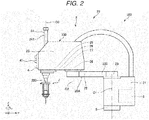
- FIG. 2 is the side view of the robot provided in the robot system shown in FIG. 1 .
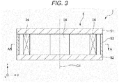
- FIG. 3 is the longitudinal sectional view of the force detection unit provided in the robot shown in FIG. 1 .
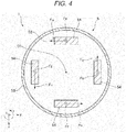
- FIG. 4 is the sectional view along line A-A in FIG. 3 .
- FIG. 5 is the functional block diagram of the robot system shown in FIG. 1 .
- FIG. 6 is the block diagram showing the hardware configuration example of the robot system shown in FIG. 5 .
- an x-axis, a y-axis, and a z-axis are shown as three axes orthogonal to one another.
- directions parallel to the x-axis are also referred to as “x-axis directions”
- directions parallel to the y-axis are also referred to as “y-axis directions”
- directions parallel to the z-axis are also referred to as "z-axis directions”.
- the pointer sides of the respective arrows in the drawings are referred to as "+ (plus)” and the tail sides are referred to as "- (minus)", the direction parallel to the +x-axis direction is also referred to as "+x-axis direction", the direction parallel to the -x-axis direction is also referred to as "-x-axis direction", the direction parallel to the +y-axis direction is also referred to as "+y-axis direction”, the direction parallel to the -y-axis direction is also referred to as "-y-axis direction”, the direction parallel to the +z-axis direction is also referred to as "+z-axis direction”, and the direction parallel to the -z-axis direction is also referred to as "-z-axis direction”. Further, directions about the z-axis and directions about an axis parallel to the z-axis are also referred to as "u-axis directions”.
- the +z-axis direction i.e., the upside in FIG. 2 is also referred to as “upper” or “above” and the -z-axis direction, i.e., the downside is also referred to as “lower” or “below”.
- a base 21 side in FIGS. 1 and 2 is referred to as “proximal end” and the opposite side, i.e., an end effector 7 side is referred to as “distal end”.
- the z-axis directions, i.e., upward and downward directions in FIG. 2 are referred to as “vertical directions” and the x-axis directions and the y-axis directions, i.e., leftward and rightward directions are referred to as "horizontal directions”.
- a robot system 100 shown in FIG. 1 is used for work of e.g. holding, transport, assembly, inspection, etc. of works including electronic components and electronic apparatuses.
- the robot system 100 includes a robot 2 and an instruction apparatus 3 that instructs the robot 2 to execute an operation program.
- the robot 2 and the instruction apparatus 3 can communicate via wired or wireless connection and the communication may be made via a network such as the Internet.
- the robot 2 is a horizontal articulated robot, i.e., a scalar robot in the configuration shown in FIG. 2 .
- the robot 2 includes a base 21, a robot arm 20 coupled to the base 21, a receiving unit 4 that receives a predetermined operation from an operator, a force detection unit 5, an end effector 7, and a control apparatus 8 that controls actuation of these respective units.
- the robot arm 20, the base 21, the receiving unit 4, and the force detection unit 5 form a robot main body 20A.
- the robot arm 20 includes a first arm 22, a second arm 23, and a third arm 24 as a working head.
- robot 2 is not limited to the illustrated configuration, but the number of arms may be one, two, four, or more.
- the robot 2 includes a drive unit 25 that rotates the first arm 22 relative to the base 21, a drive unit 26 that rotates the second arm 23 relative to the first arm 22, a u-drive unit 27 that rotates a shaft 241 of the third arm 24 relative to the second arm 23, a z-drive unit 28 that moves the shaft 241 in the z-axis directions relative to the second arm 23, and an angular velocity sensor 29.
- the drive unit 25 is provided inside of a housing 220 of the first arm 22 and has a motor 251 that generates a drive force, a reducer 252 that reduces the drive force of the motor 251, and a position sensor 253 that detects the rotation angle of the rotation shaft of the motor 251 or the reducer 252.
- the drive unit 26 is provided inside of a housing 230 of the second arm 23 and has a motor 261 that generates a drive force, a reducer 262 that reduces the drive force of the motor 261, and a position sensor 263 that detects the rotation angle of the rotation shaft of the motor 261 or the reducer 262.
- the u-drive unit 27 is provided inside of the housing 230 of the second arm 23 and has a motor 271 that generates a drive force, a reducer 272 that reduces the drive force of the motor 271, and a position sensor 273 that detects the rotation angle of the rotation shaft of the motor 271 or the reducer 272.
- the z-drive unit 28 is provided inside of the housing 230 of the second arm 23 and has a motor 281 that generates a drive force, a reducer 282 that reduces the drive force of the motor 281, and a position sensor 283 that detects the rotation angle of the rotation shaft of the motor 281 or the reducer 282.
- the motor 251, the motor 261, the motor 271, and the motor 281, e.g. servo motors such as AC servo motors or DC servo motors may be used.
- the reducer 252 the reducer 262, the reducer 272, and the reducer 282, e.g. planet gear reducers, wave gearings, or the like may be used.
- the position sensor 253, the position sensor 263, the position sensor 273, and the position sensor 283, e.g. angle sensors may be used.
- the drive unit 25, the drive unit 26, the u-drive unit 27, and the z-drive unit 28 are respectively coupled to corresponding motor drivers (not shown) and controlled by a robot control unit 81 of the control apparatus 8 via the motor drivers.
- the angular velocity sensor 29 is provided inside of the second arm 23. Accordingly, the sensor may detect the angular velocity of the second arm 23.
- the control apparatus 8 performs control of the robot 2 based on information of the detected angular velocity.
- the base 21 is fixed to a floor surface (not shown) by bolts or the like.
- the first arm 22 is coupled to the upper end portion of the base 21.
- the first arm 22 is rotatable about a first axis O1 along the vertical directions relative to the base 21.
- the drive unit 25 that rotates the first arm 22 drives, the first arm 22 rotates within a horizontal plane about the first axis O1 relative to the base 21.
- the position sensor 253 is configured to detect the amount of rotation of the first arm 22 relative to the base 21.
- the second arm 23 is coupled to the distal end portion of the first arm 22.
- the second arm 23 is rotatable about a second axis O2 along the vertical directions relative to the first arm 22.
- the axial direction of the first axis O1 is the same as the axial direction of the second axis O2. That is, the second axis O2 is parallel to the first axis O1.
- the position sensor 263 is configured to detect the amount of drive, i.e., the amount of rotation of the second arm 23 relative to the first arm 22.
- the third arm 24 is placed and supported in the distal end portion of the second arm 23.
- the third arm 24 has the shaft 241.
- the shaft 241 is rotatable about a third axis O3 along the vertical directions relative to the second arm 23 and movable in the upward and downward directions.
- the shaft 241 is the arm at the most distal end of the robot arm 20.
- the shaft 241 rotates about the z-axis. Further, the position sensor 273 is configured to detect the amount of rotation of the shaft 241 relative to the second arm 23.
- the shaft 241 moves in the upward and downward directions, i.e., in the z-axis directions.
- the position sensor 283 is configured to detect the amount of movement of the shaft 241 in the z-axis directions relative to the second arm 23.
- the robot arm 20 has the first arm 22, the second arm 23 coupled to the first arm 22 at the opposite side to the base 21 and pivoting about the second axis O2 parallel to the first axis O1, and the third arm 24 supported by the second arm 23 and moving along the axial direction of the third axis O3 in a different position from the second axis O2 and parallel to the second axis O2.
- the movable range in the xy plane may be sufficiently secured by the first arm 22 and the second arm 23, and the robot arm may be also actuated in the z-axis directions by the third arm 24.
- a distal end coordinate system having the origin at the control point is set.
- the distal end coordinate system and a robot coordinate system with reference to the origin set in the base 21 were calibrated and coordinates in the distal end coordinate system may be obtained from coordinates in the robot coordinate system by calculation.
- control point may be set at the distal end of the end effector 7.
- various end effectors are detachably coupled to the distal end portion of the shaft 241.
- the end effector is not particularly limited to, but includes e.g. one that grips an object to be transported, one that processes an object to be processed, and one used for inspection.
- the end effector 7 is detachably coupled.
- the end effector 7 is not a component element of the robot 2 in the embodiment, however, a part or entire of the end effector 7 may be a component element of the robot 2. Or, the end effector 7 is not a component element of the robot arm 20 in the embodiment, however, a part or entire of the end effector 7 may be a component element of the robot arm 20.
- the force detection unit 5 detects a force applied to the robot 2, i.e., a force applied to the robot arm 20 and the base 21.
- the force detection unit 5 is provided at the downside of the base 21, i.e., the -z-axis side and supports the base 21 from the downside.
- the force detection unit 5 is a member having a first plate 51, a second plate 52, a tubular portion 53 placed between the first plate 51 and the second plate 52, a plurality of, in the embodiment, four elements 54, and a columnar outer shape. Further, the four elements 54 are sandwiched between the first plate 51 and the second plate 52.
- the number of the elements 54 is not limited to that, but may be three or less, five, or more.
- the first plate 51 and the second plate 52 have circular plate shapes and placed apart sequentially from the +z-axis side. Note that the shapes of the first plate 51 and the second plate 52 in the plan view may be any shapes, not limited to the circular shapes.
- the tubular portion 53 has a cylinder shape and a function of protecting the elements 54.
- the respective elements 54 are placed to form a circular shape at equal intervals. Thereby, the forces applied to the respective elements 54 are as uniform as possible and the forces may be accurately detected.
- each element 54 e.g. an element formed using a piezoelectric material such as quartz crystal and outputting electric charge when subjected to an external force may be used.
- the control apparatus 8 may perform conversion into an external force applied to the end effector 7 according to the amounts of electric charge. Further, such a piezoelectric material can adjust the direction in which the electric charge may be generated when the material is subjected to the external force according to the direction in which the material is placed.
- each element 54 may detect a force Fz as a component in the vertical direction and a force Fu about the z-axis, i.e., in the u-axis direction. That is, the force detection unit 5 detects the force Fz in the axial direction of the third axis O3. Thereby, the work of moving the shaft 241 along the z-axis directions may be performed more accurately.
- the receiving unit 4 is provided in the distal end portion of the robot arm 20, i.e., at the -y-axis side of the second arm 23. Specifically, the receiving unit 4 is placed on the outer surface of the housing 230 of the second arm 23 to face the -y-axis side.
- the receiving unit 4 is a part that receives a predetermined operation by the operator.
- the receiving unit 4 includes a switch and is formed by an operation button 41 as an example.
- the predetermined operation performed by the operator is an action of pressing.
- the operation button 41 may be a mechanical button or touch-electric button.
- a button having a different function such as a button for teaching may be placed around the operation button 41.
- the switch is not limited to the above described buttons, but a toggle switch, rocker switch, rotary switch, slide switch, or the like may be used.
- the robot main body 20A has the robot arm 20 and the receiving unit 4 is the operation button 41 as the switch provided in the robot arm 20.
- the operator near the robot arm 20 during teaching or the like or operating the robot arm 20 may easily perform operation of the receiving unit 4.
- the receiving unit 4 is not limited to the above described switches, but an optical or capacitive proximity sensor may be used and may receive operation when the operator approaches at a predetermined distance.
- the force detection unit 5 may detect the received force and receive the operation.
- the force detection unit 5 functions as the receiving unit 4.
- "Predetermined operation” in this case includes pushing, pulling, tapping of the robot arm 20 by the operator.
- the control apparatus 8 is provided inside of the base 21 in the embodiment. Further, as shown in FIG. 5 , the control apparatus 8 has a function of controlling driving of the robot 2 and is electrically coupled to the above described respective parts of the robot 2.
- the control apparatus 8 includes the robot control unit 81, a storage unit 82, and a communication unit 83. These respective units are coupled communicably with one another.
- the robot control unit 81 executes various programs etc. stored in the storage unit 82. Thereby, processing including control of driving of the robot 2, various calculations, and various determinations is realized.
- the storage unit 82 stores operation programs executed by the robot control unit 81.
- the programs are prepared with respect to each work and stored to be updatable as needed. Further, the storage unit 82 may be configured to store other data than the programs.
- the other data than the programs includes e.g. setting information and maintenance history of the control apparatus 8.
- the communication unit 83 performs communication between the control apparatus 8 and the corresponding robot main body 20A and communication between the control apparatus 8 and the instruction apparatus 3. Further, the communication unit 83 functions as a transmitting unit that, when the receiving unit 4 receives the operation, transmits information representing reception of the operation.
- control apparatus 8 can be realized by e.g. a hardware configuration shown in FIG. 6 .
- the control apparatus 8 shown in FIG. 6 includes a processor, a memory, and an external interface communicably coupled to one another.
- the processor shown in FIG. 6 includes e.g. a CPU (Central Processing Unit).
- a CPU Central Processing Unit
- the memory shown in FIG. 6 includes e.g. a volatile memory such as a RAM (Random Access Memory), nonvolatile memory such as a ROM (Read Only Memory), etc. Note that the memory is not limited to the undetachable type but may be a detachable external memory device.
- a volatile memory such as a RAM (Random Access Memory), nonvolatile memory such as a ROM (Read Only Memory), etc.
- nonvolatile memory such as a ROM (Read Only Memory)
- the memory is not limited to the undetachable type but may be a detachable external memory device.
- the external interface shown in FIG. 6 includes various connectors for communication.
- a USB (Universal Serial Bus) connector, RS-232C connector, and wired LAN (Local Area Network) are examples.
- the external interface may be a transceiver that enables wireless communication such as a wireless LAN.
- control apparatus 8 may further include another hardware component element in addition to the above described component elements.
- the instruction apparatus 3 instructs the robot 2 to execute an operation program and instructs the robot 2 to perform an operation. Then, the control apparatus 8 of the robot 2 controls driving of the respective parts of the robot 2 based on the instruction.
- the instruction apparatus 3 has a control unit 31, a storage unit 32, an operation unit 33, a reporting unit 34 as a first reporting unit, and a communication unit 35. These respective units are communicably coupled to one another.
- the instruction apparatus 3 includes an operation apparatus that can be operated and used by the user.
- the control unit 31 controls actuation of the operation unit 33 and the reporting unit 34 based on various programs stored in the storage unit 32.
- the storage unit 32 stores programs to be executed by the control unit 31, operation programs to be executed by the control apparatus 8, etc. These programs are prepared with respect to each work and stored to be updatable as needed. Further, the storage unit 32 may be configured to store other data than the programs. The other data than the programs includes e.g. setting information and maintenance history of the control apparatus 8.
- the operator performs a predetermined operation on the operation unit 33 and the unit receives the instruction from the operator. Further, the operation unit 33 displays various windows when the operator inputs information to the instruction apparatus 3.
- the reporting unit 34 reports to the operator.
- the communication unit 35 communicates with the control apparatus 8. That is, the communication unit 35 also functions as a receiving unit that receives information transmitted by the communication unit 83. The function will be described in detail later.
- the function of the instruction apparatus 3 can be realized by e.g. a hardware configuration shown in FIG. 6 .
- the instruction apparatus 3 shown in FIG. 6 includes a processor, a memory, and an external interface communicably coupled to one another.
- the processor shown in FIG. 6 includes e.g. a CPU (Central Processing Unit).
- a CPU Central Processing Unit
- the memory shown in FIG. 6 includes e.g. a volatile memory such as a RAM (Random Access Memory), nonvolatile memory such as a ROM (Read Only Memory), etc. Note that the memory is not limited to the undetachable type but may be a detachable external memory device.
- a volatile memory such as a RAM (Random Access Memory), nonvolatile memory such as a ROM (Read Only Memory), etc.
- nonvolatile memory such as a ROM (Read Only Memory)
- the memory is not limited to the undetachable type but may be a detachable external memory device.
- the external interface shown in FIG. 6 includes various connectors for communication.
- a USB (Universal Serial Bus) connector, RS-232C connector, and wired LAN (Local Area Network) are examples.
- the external interface may be a transceiver that enables wireless communication such as a wireless LAN.
- a display device shown in FIG. 6 includes e.g. a liquid crystal monitor and displays various windows.
- the input device is a device to which the operator performs various kinds of input and includes e.g. a keyboard and a mouse.
- the screen of the display device may include a touch panel. That is, the display device and the input device may be integrally formed.
- a reporting device shown in FIG. 6 may have a visual reporting configuration, auditory reporting configuration, sensory reporting configuration, or a combination of these two or more configurations.
- visual reporting both the reporting device and the display device may be used.
- the reporting device includes a monitor displaying a predetermined character or sign, a blinking pattern, and a lamp emitting different colors of light.
- the reporting device includes various sounding devices that issue voice, warning sound, or the like.
- the instruction apparatus 3 may have a function of teaching or instruct the robot 2 to execute another operation program without teaching.
- the instruction apparatus 3 may include e.g. a personal computer and teaching pendant.
- an apparatus for an instruction uniquely created by the user using a connection interface to the control apparatus 8 may be an example of the instruction apparatus 3.
- the instruction apparatus 3 may further include another hardware component element in addition to the above described component elements.
- connection between the instruction apparatus 3 and the control apparatus 8 is wireless connection
- visual recognition of the connection condition between the instruction apparatus 3 and the control apparatus 8 is harder and effects of the present disclosure, which will be described later, may be obtained more remarkably.
- connection between the instruction apparatus 3 and the control apparatus 8 is wired connection
- the number of wires is larger and visual recognition of the connection condition between the instruction apparatus 3 and the control apparatus 8 is harder at a glance and the effects of the present disclosure to be described later may be obtained more remarkably.
- the operator operates the operation unit 33 of the instruction apparatus 3, and thereby, instructs the robot 2 to execute the operation program.
- the operation program includes e.g. a program on teaching and program on work performed by the robot 2. That is, the operator may set the robot 2 in a teaching mode or work mode using the instruction apparatus 3.
- the above described robot system 100 is used in a factory in the following manner.
- a plurality of the robots 2 are provided and one instruction apparatus 3 is placed for each robot 2. That is, a plurality of the robot systems 100 are present and these are actuated according to the operation program having the same content or different operation programs at the same time or different times.
- the problem may be solved in the following manner.
- an initial state i.e., a state in which the robot 2 and the instruction apparatus 3 are not coupled.
- the operator couples the instruction apparatus 3 to the robot 2, that is, when the communication unit 83 of the control apparatus 8 and the communication unit 35 of the instruction apparatus 3 are set to be communicable, information representing individual identification of the coupled instruction apparatus 3 is stored in the storage unit 82.
- the instruction apparatus 3 reaches a condition with a right for control on the robot 2.
- the condition with the right for control refers to a condition in which the instruction apparatus can instruct the control apparatus 8 to execute an operation program.
- the operator near the robot 2 may know the instruction apparatus 3 in the condition with the right for control on the robot 2. Therefore, the operator may operate the instruction apparatus 3 while knowing the robot 2 to perform operation. As a result, safety of the operator is secured.
- the reporting unit 34 may be configured to report for a preset time or while the receiving unit 4 is operated.
- the reporting unit 34 may be configured not to report or report that the corresponding instruction apparatus 3 is not present.
- control apparatus 8 When the operator operates the operation button 41 of the receiving unit 4, for example, when the control apparatus 8 and the instruction apparatus 3 are in the offline status, the control apparatus 8 may transmit a signal for returning to the online status. Thereby, the work may be smoothly restarted.
- the robot system 100 includes the robot 2 having the robot main body 20A having the receiving unit 4 that receives the predetermined operation, the control apparatus 8 that controls the actuation of the robot main body 20A, and the communication unit 83 as the transmitting unit that transmits information representing reception of the operation when the receiving unit 4 receives the operation, and the instruction apparatus 3 having the communication unit 35 as the receiving unit that receives the information transmitted by the communication unit 83 and the reporting unit 34 as the first reporting unit and instructing the control apparatus 8 to execute the operation program.
- the instruction apparatus 3 is in the condition with the right for control as the condition in which the instruction apparatus 3 can instruct the control apparatus 8 to execute the operation program
- the reporting unit 34 reports that the instruction apparatus 3 is in the condition with the right for control.
- the operator near the robot 2 may know the instruction apparatus 3 in the condition with the right for control on the robot 2. Therefore, the operator may operate the instruction apparatus 3 while knowing the robot 2 to perform the operation. As a result, the safety of the operator is secured.
- FIG. 7 is the schematic configuration diagram of the second embodiment of the robot system according to the present disclosure.
- a robot system 100A has the robot 2 and a plurality of the instruction apparatuses 3.
- the robot 2 is respectively communicable with the plurality of instruction apparatuses 3.
- the respective instruction apparatuses 3 include the apparatuses exemplified in the above described first embodiment and are of different types from one another. Note that the plurality of the instruction apparatuses 3 may include a plurality of the same type of the apparatuses.
- the plurality of the instruction apparatuses 3 are communicable with the robot 2, however, only one of the instruction apparatuses 3 is in the condition with the right for control. That is, one instruction apparatus of the respective instruction apparatuses 3 instructs the robot 2 to execute the operation program.
- Priorities are set with respect to each type of the instruction apparatus 3, and the instruction apparatus 3 to which the right for control is provided is selected based on the priorities. For example, information on the priorities with respect to each type of the instruction apparatus 3 may be stored in the storage unit 82 of the control apparatus 8 in advance, one of the respective instruction apparatuses 3 with confirmed coupling may be selected based on the priorities and input of the operation program may be received only from the instruction apparatus 3.
- the robot system 100A of the embodiment includes the plurality of instruction apparatuses 3. Further, the robot 2 is instructed to execute the operation program by one instruction apparatus 3 of the plurality of instruction apparatuses 3. In this case, it is particularly hard for the operator near the robot 2 to know the instruction apparatus 3 in the condition with the right for control on the robot 2. Therefore, under the situation, the effects of the present disclosure may be obtained more remarkably.
- FIG. 8 is the schematic configuration diagram of the third embodiment of the robot system according to the present disclosure.
- a robot system 100B has a plurality of the robots 2 and the instruction apparatus 3.
- the instruction apparatus 3 is respectively communicable with the respective robots 2.
- the respective robots 2 may be of the same type or different types of robots may be mixed.
- the instruction apparatus 3 is communicable with the plurality of robots 2, however, the instruction apparatus 3 may be in the condition with the right for control on only one robot 2 or in the condition with the right for control on each of the plurality of robots 2.
- the instruction apparatus 3 may be in the condition with the right for control on the plurality of robots 2. In this case, it is particularly hard for the operator near the robot 2 to know the instruction apparatus 3 in the condition with the right for control on the robot 2. Therefore, under the situation, the effects of the present disclosure may be obtained more remarkably.
- FIG. 9 is the schematic configuration diagram of the fourth embodiment of the robot system according to the present disclosure.
- the robot 2 of a robot system 100C has a plurality of the robot main bodies 20A and one control apparatus 8.
- the control apparatus 8 is separately formed from the robot main bodies 20A and has a housing different from the bases 21.
- the control apparatus 8 is respectively coupled to the plurality of robot main bodies 20A and may independently control the respective robot main bodies 20A at the same time or different times. Further, the control apparatus 8 is configured to couple to a plurality of the instruction apparatuses 3.
- the control apparatus 8 has a reporting unit 84 as a second reporting unit.
- the reporting unit 84 includes one having the configuration exemplified in the reporting device of the first embodiment.
- the reporting unit 34 of the instruction apparatus 3 in the condition with the right for control performs reporting like the above described embodiment.
- the control apparatus 8 can control the actuation of the robot main body 20A received the operation, the reporting unit 84 of the control apparatus 8 performs reporting thereon.
- FIG. 9 in an environment in which a plurality of the control apparatuses 8 are present, by which control apparatus 8 the robot main body 20A performed the operation on the receiving unit 4 is controlled may be known at a glance.
- the robot 2 has the plurality of robot main bodies 20A.
- the control apparatus 8 is separately formed from the plurality of robot main bodies 20A and respectively independently controls the actuation of the plurality of robot main bodies 20A, i.e., the actuation of the robot main bodies 20A. According to the configuration, compared to a case where one control apparatus 8 is coupled to one robot main body 20A, the number of control apparatuses 8 may be reduced. Therefore, the coupling status may be known more easily.
- control apparatus 8 has the reporting unit 84 as the second reporting unit.
- the reporting unit 84 reports that the control apparatus 8 can control the actuation of the robot main body 20A.
- the robot system according to the present disclosure is explained based on the illustrated embodiments, however, the present disclosure is not limited to those.
- the configurations of the respective parts may be replaced by arbitrary configurations having the same functions. Further, other arbitrary configurations may be added to the above described embodiments of the robot system.
- the robot system according to the present disclosure may be formed by a combination of the features of the above described embodiments.
Landscapes
- Engineering & Computer Science (AREA)
- Robotics (AREA)
- Mechanical Engineering (AREA)
- Automation & Control Theory (AREA)
- Physics & Mathematics (AREA)
- General Engineering & Computer Science (AREA)
- Manufacturing & Machinery (AREA)
- Quality & Reliability (AREA)
- Human Computer Interaction (AREA)
- General Physics & Mathematics (AREA)
- Artificial Intelligence (AREA)
- Evolutionary Computation (AREA)
- Fuzzy Systems (AREA)
- Mathematical Physics (AREA)
- Software Systems (AREA)
- Manipulator (AREA)
Abstract
Description
- The present application is based on, and claims priority from
JP Application Serial Number 2019-199280, filed October 31, 2019 - The present disclosure relates to a robot system.
- Recently, in factories, due to labor cost rise and labor shortage, work manually performed in the past has been increasingly automated by various robots and robot peripherals. The various robots have e.g. arms and controllers as control units that control actuation of the arms. Further, in
JP-A-2015-44281 - In some production lines using robots, for example, a plurality of controllers and a plurality of operation devices are mixed in one factory. In this case, to which operation device one controller is connected may be confused. To prevent this, in
JP-A-2015-44281 - However, in
JP-A-2015-44281 - A robot system according to an application example includes a robot including a robot main body having a receiving unit that receives a predetermined operation, a control apparatus that controls actuation of the robot main body, and a transmitting unit that, when the receiving unit receives the operation, transmits information representing reception of the operation, and an instruction apparatus having a receiving unit that receives the information transmitted by the transmitting unit and a first reporting unit, and instructing the control apparatus to execute an operation program, wherein, when the instruction apparatus is in a condition with a right for control in which the instruction apparatus can instruct the control apparatus to execute the operation program, when the receiving unit receives the information, the first reporting unit reports that the instruction apparatus is in the condition with the right for control.
-
-
FIG. 1 is a schematic configuration diagram of a first embodiment of a robot system according to the present disclosure. -
FIG. 2 is a side view of a robot provided in the robot system shown inFIG. 1 . -
FIG. 3 is a longitudinal sectional view of a force detection unit provided in the robot shown inFIG. 1 . -
FIG. 4 is a sectional view along line A-A inFIG. 3 . -
FIG. 5 is a functional block diagram of the robot system shown inFIG. 1 . -
FIG. 6 is a block diagram showing a hardware configuration example of the robot system shown inFIG. 5 . -
FIG. 7 is a schematic configuration diagram of a second embodiment of the robot system according to the present disclosure. -
FIG. 8 is a schematic configuration diagram of a third embodiment of the robot system according to the present disclosure. -
FIG. 9 is a schematic configuration diagram of a fourth embodiment of the robot system according to the present disclosure. - As below, a robot system according to the present disclosure will be explained in detail based on preferred embodiments shown in the accompanying drawings.
-
FIG. 1 is the schematic configuration diagram of the first embodiment of the robot system according to the present disclosure.FIG. 2 is the side view of the robot provided in the robot system shown inFIG. 1 .FIG. 3 is the longitudinal sectional view of the force detection unit provided in the robot shown inFIG. 1 .FIG. 4 is the sectional view along line A-A inFIG. 3 .FIG. 5 is the functional block diagram of the robot system shown inFIG. 1 .FIG. 6 is the block diagram showing the hardware configuration example of the robot system shown inFIG. 5 . - In
FIG. 2 , for convenience of explanation, an x-axis, a y-axis, and a z-axis are shown as three axes orthogonal to one another. Hereinafter, directions parallel to the x-axis are also referred to as "x-axis directions", directions parallel to the y-axis are also referred to as "y-axis directions", and directions parallel to the z-axis are also referred to as "z-axis directions". Further, hereinafter, the pointer sides of the respective arrows in the drawings are referred to as "+ (plus)" and the tail sides are referred to as "- (minus)", the direction parallel to the +x-axis direction is also referred to as "+x-axis direction", the direction parallel to the -x-axis direction is also referred to as "-x-axis direction", the direction parallel to the +y-axis direction is also referred to as "+y-axis direction", the direction parallel to the -y-axis direction is also referred to as "-y-axis direction", the direction parallel to the +z-axis direction is also referred to as "+z-axis direction", and the direction parallel to the -z-axis direction is also referred to as "-z-axis direction". Further, directions about the z-axis and directions about an axis parallel to the z-axis are also referred to as "u-axis directions". - Hereinafter, for convenience of explanation, the +z-axis direction, i.e., the upside in
FIG. 2 is also referred to as "upper" or "above" and the -z-axis direction, i.e., the downside is also referred to as "lower" or "below". Further, with respect to arobot arm 20, abase 21 side inFIGS. 1 and2 is referred to as "proximal end" and the opposite side, i.e., anend effector 7 side is referred to as "distal end". Furthermore, the z-axis directions, i.e., upward and downward directions inFIG. 2 are referred to as "vertical directions" and the x-axis directions and the y-axis directions, i.e., leftward and rightward directions are referred to as "horizontal directions". - A
robot system 100 shown inFIG. 1 is used for work of e.g. holding, transport, assembly, inspection, etc. of works including electronic components and electronic apparatuses. Therobot system 100 includes arobot 2 and aninstruction apparatus 3 that instructs therobot 2 to execute an operation program. Therobot 2 and theinstruction apparatus 3 can communicate via wired or wireless connection and the communication may be made via a network such as the Internet. - The
robot 2 is a horizontal articulated robot, i.e., a scalar robot in the configuration shown inFIG. 2 . As shown inFIG. 2 , therobot 2 includes abase 21, arobot arm 20 coupled to thebase 21, areceiving unit 4 that receives a predetermined operation from an operator, aforce detection unit 5, anend effector 7, and acontrol apparatus 8 that controls actuation of these respective units. The robot arm 20, thebase 21, thereceiving unit 4, and theforce detection unit 5 form a robotmain body 20A. - The
robot arm 20 includes afirst arm 22, asecond arm 23, and athird arm 24 as a working head. - Note that the
robot 2 is not limited to the illustrated configuration, but the number of arms may be one, two, four, or more. - Further, the
robot 2 includes adrive unit 25 that rotates thefirst arm 22 relative to thebase 21, adrive unit 26 that rotates thesecond arm 23 relative to thefirst arm 22, au-drive unit 27 that rotates ashaft 241 of thethird arm 24 relative to thesecond arm 23, a z-drive unit 28 that moves theshaft 241 in the z-axis directions relative to thesecond arm 23, and anangular velocity sensor 29. - As shown in
FIGS. 2 and5 , thedrive unit 25 is provided inside of ahousing 220 of thefirst arm 22 and has amotor 251 that generates a drive force, areducer 252 that reduces the drive force of themotor 251, and aposition sensor 253 that detects the rotation angle of the rotation shaft of themotor 251 or thereducer 252. - The
drive unit 26 is provided inside of ahousing 230 of thesecond arm 23 and has amotor 261 that generates a drive force, areducer 262 that reduces the drive force of themotor 261, and aposition sensor 263 that detects the rotation angle of the rotation shaft of themotor 261 or thereducer 262. - The
u-drive unit 27 is provided inside of thehousing 230 of thesecond arm 23 and has amotor 271 that generates a drive force, areducer 272 that reduces the drive force of themotor 271, and aposition sensor 273 that detects the rotation angle of the rotation shaft of themotor 271 or thereducer 272. - The z-
drive unit 28 is provided inside of thehousing 230 of thesecond arm 23 and has amotor 281 that generates a drive force, areducer 282 that reduces the drive force of themotor 281, and aposition sensor 283 that detects the rotation angle of the rotation shaft of themotor 281 or thereducer 282. - As the
motor 251, themotor 261, themotor 271, and themotor 281, e.g. servo motors such as AC servo motors or DC servo motors may be used. - As the
reducer 252, thereducer 262, thereducer 272, and thereducer 282, e.g. planet gear reducers, wave gearings, or the like may be used. Further, as theposition sensor 253, theposition sensor 263, theposition sensor 273, and theposition sensor 283, e.g. angle sensors may be used. - The
drive unit 25, thedrive unit 26, theu-drive unit 27, and the z-drive unit 28 are respectively coupled to corresponding motor drivers (not shown) and controlled by arobot control unit 81 of thecontrol apparatus 8 via the motor drivers. - As shown in
FIG. 2 , theangular velocity sensor 29 is provided inside of thesecond arm 23. Accordingly, the sensor may detect the angular velocity of thesecond arm 23. Thecontrol apparatus 8 performs control of therobot 2 based on information of the detected angular velocity. - The
base 21 is fixed to a floor surface (not shown) by bolts or the like. Thefirst arm 22 is coupled to the upper end portion of thebase 21. Thefirst arm 22 is rotatable about a first axis O1 along the vertical directions relative to thebase 21. When thedrive unit 25 that rotates thefirst arm 22 drives, thefirst arm 22 rotates within a horizontal plane about the first axis O1 relative to thebase 21. Theposition sensor 253 is configured to detect the amount of rotation of thefirst arm 22 relative to thebase 21. - The
second arm 23 is coupled to the distal end portion of thefirst arm 22. Thesecond arm 23 is rotatable about a second axis O2 along the vertical directions relative to thefirst arm 22. The axial direction of the first axis O1 is the same as the axial direction of the second axis O2. That is, the second axis O2 is parallel to the first axis O1. When thedrive unit 26 that rotates thesecond arm 23 drives, thesecond arm 23 rotates within a horizontal plane about the second axis O2 relative to thefirst arm 22. Theposition sensor 263 is configured to detect the amount of drive, i.e., the amount of rotation of thesecond arm 23 relative to thefirst arm 22. - The
third arm 24 is placed and supported in the distal end portion of thesecond arm 23. Thethird arm 24 has theshaft 241. Theshaft 241 is rotatable about a third axis O3 along the vertical directions relative to thesecond arm 23 and movable in the upward and downward directions. Theshaft 241 is the arm at the most distal end of therobot arm 20. - When the
u-drive unit 27 that rotates theshaft 241 drives, theshaft 241 rotates about the z-axis. Further, theposition sensor 273 is configured to detect the amount of rotation of theshaft 241 relative to thesecond arm 23. - When the z-
drive unit 28 that moves theshaft 241 in the z-axis directions drives, theshaft 241 moves in the upward and downward directions, i.e., in the z-axis directions. Further, theposition sensor 283 is configured to detect the amount of movement of theshaft 241 in the z-axis directions relative to thesecond arm 23. - As described above, the
robot arm 20 has thefirst arm 22, thesecond arm 23 coupled to thefirst arm 22 at the opposite side to thebase 21 and pivoting about the second axis O2 parallel to the first axis O1, and thethird arm 24 supported by thesecond arm 23 and moving along the axial direction of the third axis O3 in a different position from the second axis O2 and parallel to the second axis O2. The movable range in the xy plane may be sufficiently secured by thefirst arm 22 and thesecond arm 23, and the robot arm may be also actuated in the z-axis directions by thethird arm 24. - In the
robot 2, with the distal end of theshaft 241 as a control point, a distal end coordinate system having the origin at the control point is set. The distal end coordinate system and a robot coordinate system with reference to the origin set in thebase 21 were calibrated and coordinates in the distal end coordinate system may be obtained from coordinates in the robot coordinate system by calculation. - Note that the control point may be set at the distal end of the
end effector 7. - Further, various end effectors are detachably coupled to the distal end portion of the
shaft 241. The end effector is not particularly limited to, but includes e.g. one that grips an object to be transported, one that processes an object to be processed, and one used for inspection. In the embodiment, theend effector 7 is detachably coupled. - The
end effector 7 is not a component element of therobot 2 in the embodiment, however, a part or entire of theend effector 7 may be a component element of therobot 2. Or, theend effector 7 is not a component element of therobot arm 20 in the embodiment, however, a part or entire of theend effector 7 may be a component element of therobot arm 20. - As shown in
FIGS. 2 to 4 , theforce detection unit 5 detects a force applied to therobot 2, i.e., a force applied to therobot arm 20 and thebase 21. Theforce detection unit 5 is provided at the downside of thebase 21, i.e., the -z-axis side and supports the base 21 from the downside. - Further, as shown in
FIG. 3 , theforce detection unit 5 is a member having afirst plate 51, asecond plate 52, atubular portion 53 placed between thefirst plate 51 and thesecond plate 52, a plurality of, in the embodiment, fourelements 54, and a columnar outer shape. Further, the fourelements 54 are sandwiched between thefirst plate 51 and thesecond plate 52. The number of theelements 54 is not limited to that, but may be three or less, five, or more. - The
first plate 51 and thesecond plate 52 have circular plate shapes and placed apart sequentially from the +z-axis side. Note that the shapes of thefirst plate 51 and thesecond plate 52 in the plan view may be any shapes, not limited to the circular shapes. - In the embodiment, the
tubular portion 53 has a cylinder shape and a function of protecting theelements 54. - The
respective elements 54 are placed to form a circular shape at equal intervals. Thereby, the forces applied to therespective elements 54 are as uniform as possible and the forces may be accurately detected. - As each
element 54, e.g. an element formed using a piezoelectric material such as quartz crystal and outputting electric charge when subjected to an external force may be used. Thecontrol apparatus 8 may perform conversion into an external force applied to theend effector 7 according to the amounts of electric charge. Further, such a piezoelectric material can adjust the direction in which the electric charge may be generated when the material is subjected to the external force according to the direction in which the material is placed. - In the embodiment, as shown in
FIG. 4 , eachelement 54 may detect a force Fz as a component in the vertical direction and a force Fu about the z-axis, i.e., in the u-axis direction. That is, theforce detection unit 5 detects the force Fz in the axial direction of the third axis O3. Thereby, the work of moving theshaft 241 along the z-axis directions may be performed more accurately. - As shown in
FIG. 2 , the receivingunit 4 is provided in the distal end portion of therobot arm 20, i.e., at the -y-axis side of thesecond arm 23. Specifically, the receivingunit 4 is placed on the outer surface of thehousing 230 of thesecond arm 23 to face the -y-axis side. - Further, the receiving
unit 4 is a part that receives a predetermined operation by the operator. In the embodiment, the receivingunit 4 includes a switch and is formed by anoperation button 41 as an example. In this case, the predetermined operation performed by the operator is an action of pressing. Theoperation button 41 may be a mechanical button or touch-electric button. - Or, a button having a different function such as a button for teaching may be placed around the
operation button 41. - The switch is not limited to the above described buttons, but a toggle switch, rocker switch, rotary switch, slide switch, or the like may be used.
- As described above, the robot
main body 20A has therobot arm 20 and the receivingunit 4 is theoperation button 41 as the switch provided in therobot arm 20. Thereby, for example, the operator near therobot arm 20 during teaching or the like or operating therobot arm 20 may easily perform operation of the receivingunit 4. - Further, the receiving
unit 4 is not limited to the above described switches, but an optical or capacitive proximity sensor may be used and may receive operation when the operator approaches at a predetermined distance. - When the operator applies an external force to a predetermined part of the
robot arm 20, theforce detection unit 5 may detect the received force and receive the operation. In this case, theforce detection unit 5 functions as the receivingunit 4. "Predetermined operation" in this case includes pushing, pulling, tapping of therobot arm 20 by the operator. - Next, the
control apparatus 8 will be explained. - As shown in
FIGS. 1 and2 , thecontrol apparatus 8 is provided inside of the base 21 in the embodiment. Further, as shown inFIG. 5 , thecontrol apparatus 8 has a function of controlling driving of therobot 2 and is electrically coupled to the above described respective parts of therobot 2. Thecontrol apparatus 8 includes therobot control unit 81, astorage unit 82, and acommunication unit 83. These respective units are coupled communicably with one another. - The
robot control unit 81 executes various programs etc. stored in thestorage unit 82. Thereby, processing including control of driving of therobot 2, various calculations, and various determinations is realized. - The
storage unit 82 stores operation programs executed by therobot control unit 81. The programs are prepared with respect to each work and stored to be updatable as needed. Further, thestorage unit 82 may be configured to store other data than the programs. The other data than the programs includes e.g. setting information and maintenance history of thecontrol apparatus 8. - The
communication unit 83 performs communication between thecontrol apparatus 8 and the corresponding robotmain body 20A and communication between thecontrol apparatus 8 and theinstruction apparatus 3. Further, thecommunication unit 83 functions as a transmitting unit that, when the receivingunit 4 receives the operation, transmits information representing reception of the operation. - The function of the
control apparatus 8 can be realized by e.g. a hardware configuration shown inFIG. 6 . - The
control apparatus 8 shown inFIG. 6 includes a processor, a memory, and an external interface communicably coupled to one another. - The processor shown in
FIG. 6 includes e.g. a CPU (Central Processing Unit). - The memory shown in
FIG. 6 includes e.g. a volatile memory such as a RAM (Random Access Memory), nonvolatile memory such as a ROM (Read Only Memory), etc. Note that the memory is not limited to the undetachable type but may be a detachable external memory device. - The external interface shown in
FIG. 6 includes various connectors for communication. A USB (Universal Serial Bus) connector, RS-232C connector, and wired LAN (Local Area Network) are examples. Or, the external interface may be a transceiver that enables wireless communication such as a wireless LAN. - Or, the
control apparatus 8 may further include another hardware component element in addition to the above described component elements. - Next, the
instruction apparatus 3 will be explained. - As shown in
FIG. 5 , theinstruction apparatus 3 instructs therobot 2 to execute an operation program and instructs therobot 2 to perform an operation. Then, thecontrol apparatus 8 of therobot 2 controls driving of the respective parts of therobot 2 based on the instruction. Theinstruction apparatus 3 has acontrol unit 31, astorage unit 32, anoperation unit 33, areporting unit 34 as a first reporting unit, and acommunication unit 35. These respective units are communicably coupled to one another. Theinstruction apparatus 3 includes an operation apparatus that can be operated and used by the user. - The
control unit 31 controls actuation of theoperation unit 33 and thereporting unit 34 based on various programs stored in thestorage unit 32. - The
storage unit 32 stores programs to be executed by thecontrol unit 31, operation programs to be executed by thecontrol apparatus 8, etc. These programs are prepared with respect to each work and stored to be updatable as needed. Further, thestorage unit 32 may be configured to store other data than the programs. The other data than the programs includes e.g. setting information and maintenance history of thecontrol apparatus 8. - The operator performs a predetermined operation on the
operation unit 33 and the unit receives the instruction from the operator. Further, theoperation unit 33 displays various windows when the operator inputs information to theinstruction apparatus 3. - The
reporting unit 34 reports to the operator. - The
communication unit 35 communicates with thecontrol apparatus 8. That is, thecommunication unit 35 also functions as a receiving unit that receives information transmitted by thecommunication unit 83. The function will be described in detail later. - The function of the
instruction apparatus 3 can be realized by e.g. a hardware configuration shown inFIG. 6 . - The
instruction apparatus 3 shown inFIG. 6 includes a processor, a memory, and an external interface communicably coupled to one another. - The processor shown in
FIG. 6 includes e.g. a CPU (Central Processing Unit). - The memory shown in
FIG. 6 includes e.g. a volatile memory such as a RAM (Random Access Memory), nonvolatile memory such as a ROM (Read Only Memory), etc. Note that the memory is not limited to the undetachable type but may be a detachable external memory device. - The external interface shown in
FIG. 6 includes various connectors for communication. A USB (Universal Serial Bus) connector, RS-232C connector, and wired LAN (Local Area Network) are examples. Or, the external interface may be a transceiver that enables wireless communication such as a wireless LAN. - A display device shown in
FIG. 6 includes e.g. a liquid crystal monitor and displays various windows. The input device is a device to which the operator performs various kinds of input and includes e.g. a keyboard and a mouse. Or, the screen of the display device may include a touch panel. That is, the display device and the input device may be integrally formed. - A reporting device shown in
FIG. 6 may have a visual reporting configuration, auditory reporting configuration, sensory reporting configuration, or a combination of these two or more configurations. In the case of visual reporting, both the reporting device and the display device may be used. - In the case of visual reporting, the reporting device includes a monitor displaying a predetermined character or sign, a blinking pattern, and a lamp emitting different colors of light.
- In the case of auditory reporting, the reporting device includes various sounding devices that issue voice, warning sound, or the like.
- The
instruction apparatus 3 may have a function of teaching or instruct therobot 2 to execute another operation program without teaching. Theinstruction apparatus 3 may include e.g. a personal computer and teaching pendant. Further, an apparatus for an instruction uniquely created by the user using a connection interface to thecontrol apparatus 8 may be an example of theinstruction apparatus 3. - Or, the
instruction apparatus 3 may further include another hardware component element in addition to the above described component elements. - When the connection between the
instruction apparatus 3 and thecontrol apparatus 8 is wireless connection, visual recognition of the connection condition between theinstruction apparatus 3 and thecontrol apparatus 8 is harder and effects of the present disclosure, which will be described later, may be obtained more remarkably. - Or, when the connection between the
instruction apparatus 3 and thecontrol apparatus 8 is wired connection, when a plurality of theinstruction apparatuses 3 and a plurality of therobots 2 are located close to one another, the number of wires is larger and visual recognition of the connection condition between theinstruction apparatus 3 and thecontrol apparatus 8 is harder at a glance and the effects of the present disclosure to be described later may be obtained more remarkably. - The operator operates the
operation unit 33 of theinstruction apparatus 3, and thereby, instructs therobot 2 to execute the operation program. The operation program includes e.g. a program on teaching and program on work performed by therobot 2. That is, the operator may set therobot 2 in a teaching mode or work mode using theinstruction apparatus 3. - For example, the above described
robot system 100 is used in a factory in the following manner. In the configuration shown inFIG. 1 , a plurality of therobots 2 are provided and oneinstruction apparatus 3 is placed for eachrobot 2. That is, a plurality of therobot systems 100 are present and these are actuated according to the operation program having the same content or different operation programs at the same time or different times. - In this case, it is hard for the operator to know by which
instruction apparatus 3 onerobot 2 is instructed. In the present disclosure, the problem may be solved in the following manner. - As below, the explanation will be started from an initial state, i.e., a state in which the
robot 2 and theinstruction apparatus 3 are not coupled. For desired work, when the operator couples theinstruction apparatus 3 to therobot 2, that is, when thecommunication unit 83 of thecontrol apparatus 8 and thecommunication unit 35 of theinstruction apparatus 3 are set to be communicable, information representing individual identification of the coupledinstruction apparatus 3 is stored in thestorage unit 82. By the coupling, theinstruction apparatus 3 reaches a condition with a right for control on therobot 2. - Here, "the condition with the right for control" refers to a condition in which the instruction apparatus can instruct the
control apparatus 8 to execute an operation program. Once theinstruction apparatus 3 reached the condition with the right for control, even in an offline status, that is, even when the communication between thecontrol apparatus 8 and theinstruction apparatus 3 is ceased, the condition with the right for control of theinstruction apparatus 3 is continued. - Then, when the operator operates the
operation button 41 of the receivingunit 4 of therobot 2, first, information representing that the operation was performed is transmitted to thecontrol apparatus 8. Then, when thecontrol apparatus 8 transmits a report command signal to theinstruction apparatus 3 with reference to the information stored in thestorage unit 82, i.e., information representing the individual identification of thecontrol apparatus 8 in the condition with the right for control. Then, theinstruction apparatus 3 received the report command signal actuates thereporting unit 34 and reports that theinstruction apparatus 3 is in the condition with the right for control. - Thereby, the operator near the
robot 2 may know theinstruction apparatus 3 in the condition with the right for control on therobot 2. Therefore, the operator may operate theinstruction apparatus 3 while knowing therobot 2 to perform operation. As a result, safety of the operator is secured. - Or, the
reporting unit 34 may be configured to report for a preset time or while the receivingunit 4 is operated. - Note that, when, even when the operator operates the
operation button 41 of the receivingunit 4, thecorresponding instruction apparatus 3 is not present, thereporting unit 34 may be configured not to report or report that thecorresponding instruction apparatus 3 is not present. - When the operator operates the
operation button 41 of the receivingunit 4, for example, when thecontrol apparatus 8 and theinstruction apparatus 3 are in the offline status, thecontrol apparatus 8 may transmit a signal for returning to the online status. Thereby, the work may be smoothly restarted. - As described above, the
robot system 100 according to the present disclosure includes therobot 2 having the robotmain body 20A having the receivingunit 4 that receives the predetermined operation, thecontrol apparatus 8 that controls the actuation of the robotmain body 20A, and thecommunication unit 83 as the transmitting unit that transmits information representing reception of the operation when the receivingunit 4 receives the operation, and theinstruction apparatus 3 having thecommunication unit 35 as the receiving unit that receives the information transmitted by thecommunication unit 83 and thereporting unit 34 as the first reporting unit and instructing thecontrol apparatus 8 to execute the operation program. In the case where theinstruction apparatus 3 is in the condition with the right for control as the condition in which theinstruction apparatus 3 can instruct thecontrol apparatus 8 to execute the operation program, when thecommunication unit 35 receives the information, thereporting unit 34 reports that theinstruction apparatus 3 is in the condition with the right for control. Thereby, the operator near therobot 2 may know theinstruction apparatus 3 in the condition with the right for control on therobot 2. Therefore, the operator may operate theinstruction apparatus 3 while knowing therobot 2 to perform the operation. As a result, the safety of the operator is secured. -
FIG. 7 is the schematic configuration diagram of the second embodiment of the robot system according to the present disclosure. - As below, the second embodiment will be explained, and the explanation will be made with a focus on differences from the first embodiment and the explanation of the same items will be omitted.
- As shown in
FIG. 7 , arobot system 100A has therobot 2 and a plurality of theinstruction apparatuses 3. Therobot 2 is respectively communicable with the plurality ofinstruction apparatuses 3. Therespective instruction apparatuses 3 include the apparatuses exemplified in the above described first embodiment and are of different types from one another. Note that the plurality of theinstruction apparatuses 3 may include a plurality of the same type of the apparatuses. - Further, in the embodiment, the plurality of the
instruction apparatuses 3 are communicable with therobot 2, however, only one of theinstruction apparatuses 3 is in the condition with the right for control. That is, one instruction apparatus of therespective instruction apparatuses 3 instructs therobot 2 to execute the operation program. - Priorities are set with respect to each type of the
instruction apparatus 3, and theinstruction apparatus 3 to which the right for control is provided is selected based on the priorities. For example, information on the priorities with respect to each type of theinstruction apparatus 3 may be stored in thestorage unit 82 of thecontrol apparatus 8 in advance, one of therespective instruction apparatuses 3 with confirmed coupling may be selected based on the priorities and input of the operation program may be received only from theinstruction apparatus 3. - As described above, the
robot system 100A of the embodiment includes the plurality ofinstruction apparatuses 3. Further, therobot 2 is instructed to execute the operation program by oneinstruction apparatus 3 of the plurality ofinstruction apparatuses 3. In this case, it is particularly hard for the operator near therobot 2 to know theinstruction apparatus 3 in the condition with the right for control on therobot 2. Therefore, under the situation, the effects of the present disclosure may be obtained more remarkably. - Note that, in the embodiment, the configuration in which only one
instruction apparatus 3 is in the condition with the right for control is explained as an example, however, a plurality ofinstruction apparatuses 3 may be in the condition with the right for control. -
FIG. 8 is the schematic configuration diagram of the third embodiment of the robot system according to the present disclosure. - As below, the third embodiment will be explained, and the explanation will be made with a focus on differences from the first embodiment and the explanation of the same items will be omitted.
- As shown in
FIG. 8 , arobot system 100B has a plurality of therobots 2 and theinstruction apparatus 3. Theinstruction apparatus 3 is respectively communicable with therespective robots 2. Therespective robots 2 may be of the same type or different types of robots may be mixed. - Further, in the embodiment, the
instruction apparatus 3 is communicable with the plurality ofrobots 2, however, theinstruction apparatus 3 may be in the condition with the right for control on only onerobot 2 or in the condition with the right for control on each of the plurality ofrobots 2. - As described above, the
instruction apparatus 3 may be in the condition with the right for control on the plurality ofrobots 2. In this case, it is particularly hard for the operator near therobot 2 to know theinstruction apparatus 3 in the condition with the right for control on therobot 2. Therefore, under the situation, the effects of the present disclosure may be obtained more remarkably. -
FIG. 9 is the schematic configuration diagram of the fourth embodiment of the robot system according to the present disclosure. - As below, the fourth embodiment will be explained, and the explanation will be made with a focus on differences from the first embodiment and the explanation of the same items will be omitted.
- As shown in
FIG. 9 , therobot 2 of a robot system 100C has a plurality of the robotmain bodies 20A and onecontrol apparatus 8. Thecontrol apparatus 8 is separately formed from the robotmain bodies 20A and has a housing different from thebases 21. Thecontrol apparatus 8 is respectively coupled to the plurality of robotmain bodies 20A and may independently control the respective robotmain bodies 20A at the same time or different times. Further, thecontrol apparatus 8 is configured to couple to a plurality of theinstruction apparatuses 3. - Furthermore, the
control apparatus 8 has areporting unit 84 as a second reporting unit. Thereporting unit 84 includes one having the configuration exemplified in the reporting device of the first embodiment. When the receivingunit 4 receives the predetermined operation, thereporting unit 34 of theinstruction apparatus 3 in the condition with the right for control performs reporting like the above described embodiment. When thecontrol apparatus 8 can control the actuation of the robotmain body 20A received the operation, thereporting unit 84 of thecontrol apparatus 8 performs reporting thereon. Thereby, as shown inFIG. 9 , in an environment in which a plurality of thecontrol apparatuses 8 are present, by whichcontrol apparatus 8 the robotmain body 20A performed the operation on the receivingunit 4 is controlled may be known at a glance. - As described above, in the embodiment, the
robot 2 has the plurality of robotmain bodies 20A. Further, thecontrol apparatus 8 is separately formed from the plurality of robotmain bodies 20A and respectively independently controls the actuation of the plurality of robotmain bodies 20A, i.e., the actuation of the robotmain bodies 20A. According to the configuration, compared to a case where onecontrol apparatus 8 is coupled to one robotmain body 20A, the number ofcontrol apparatuses 8 may be reduced. Therefore, the coupling status may be known more easily. - Furthermore, the
control apparatus 8 has thereporting unit 84 as the second reporting unit. In the case where thecontrol apparatus 8 can control the actuation of the robotmain bodies 20A, when the receivingunit 4 receives the operation, thereporting unit 84 reports that thecontrol apparatus 8 can control the actuation of the robotmain body 20A. Thereby, in addition to the effects of the present disclosure, by whichcontrol apparatus 8 the robotmain body 20A performed the operation on the receivingunit 4 is controlled may be known at a glance. - As above, the robot system according to the present disclosure is explained based on the illustrated embodiments, however, the present disclosure is not limited to those. The configurations of the respective parts may be replaced by arbitrary configurations having the same functions. Further, other arbitrary configurations may be added to the above described embodiments of the robot system. Furthermore, the robot system according to the present disclosure may be formed by a combination of the features of the above described embodiments.
Claims (7)
- A robot system comprising:a robot including a robot main body having a receiving unit that receives a predetermined operation, a control apparatus that controls actuation of the robot main body, and a transmitting unit that, when the receiving unit receives the operation, transmits information representing reception of the operation; andan instruction apparatus having a receiving unit that receives the information transmitted by the transmitting unit and a first reporting unit, and instructing the control apparatus to execute an operation program, whereinwhen the instruction apparatus is in a condition with a right for control in which the instruction apparatus can instruct the control apparatus to execute the operation program, when the receiving unit receives the information, the first reporting unit reports that the instruction apparatus is in the condition with the right for control.
- The robot system according to claim 1, wherein
the instruction apparatus is configured to reach the condition with the right for control on a plurality of the robots. - The robot system according to claim 1, further comprising a plurality of the instruction apparatuses, wherein
the robot is instructed to execute the operation program from one of the plurality of instruction apparatuses. - The robot system according to claim 1, wherein
the robot has a plurality of the robot main bodies, and
the control apparatus is formed separately from the plurality of robot main bodies and independently controls actuation of the plurality of robot main bodies. - The robot system according to claim 1, wherein
the control apparatus has a second reporting unit, and
when the control apparatus can control actuation of the robot main body, when the receiving unit receives the operation, the second reporting unit reports that the control apparatus can control the actuation of the robot main body. - The robot system according to claim 1, wherein
the robot main body has a robot arm, and
the receiving unit is a switch provided in the robot arm. - The robot system according to claim 1, wherein
the receiving unit is a force detection unit.
Applications Claiming Priority (1)
| Application Number | Priority Date | Filing Date | Title |
|---|---|---|---|
| JP2019199280A JP7415447B2 (en) | 2019-10-31 | 2019-10-31 | robot system |
Publications (2)
| Publication Number | Publication Date |
|---|---|
| EP3815857A2 true EP3815857A2 (en) | 2021-05-05 |
| EP3815857A3 EP3815857A3 (en) | 2021-09-29 |
Family
ID=73013265
Family Applications (1)
| Application Number | Title | Priority Date | Filing Date |
|---|---|---|---|
| EP20203370.0A Withdrawn EP3815857A3 (en) | 2019-10-31 | 2020-10-22 | Robot system |
Country Status (4)
| Country | Link |
|---|---|
| US (1) | US11794339B2 (en) |
| EP (1) | EP3815857A3 (en) |
| JP (1) | JP7415447B2 (en) |
| CN (1) | CN112743539B (en) |
Families Citing this family (2)
| Publication number | Priority date | Publication date | Assignee | Title |
|---|---|---|---|---|
| US12427667B2 (en) * | 2021-08-31 | 2025-09-30 | Canon Kabushiki Kaisha | Robot system, method for controlling robot system, method for manufacturing article using robot system, system, method for controlling system, and recording medium |
| US12076857B2 (en) * | 2021-11-10 | 2024-09-03 | Robotic Technologies Of Tennessee, Llc | Method for precise, intuitive positioning of robotic welding machine |
Citations (2)
| Publication number | Priority date | Publication date | Assignee | Title |
|---|---|---|---|---|
| JP2015044281A (en) | 2013-08-02 | 2015-03-12 | 株式会社ダイヘン | Robot control system |
| JP2019199280A (en) | 2018-05-16 | 2019-11-21 | 大日本印刷株式会社 | cap |
Family Cites Families (26)
| Publication number | Priority date | Publication date | Assignee | Title |
|---|---|---|---|---|
| DE69033605T2 (en) * | 1989-05-17 | 2001-08-16 | Fujitsu Ltd., Kawasaki | Profile control system for robots |
| DE4113556C3 (en) * | 1990-04-26 | 2000-02-24 | Mazda Motor | Production facility for controlling production processes and production control processes for production processes |
| US5086401A (en) * | 1990-05-11 | 1992-02-04 | International Business Machines Corporation | Image-directed robotic system for precise robotic surgery including redundant consistency checking |
| JP3418456B2 (en) * | 1994-06-23 | 2003-06-23 | ファナック株式会社 | Robot position teaching tool and robot position teaching method |
| US6386513B1 (en) * | 1999-05-13 | 2002-05-14 | Hamayoon Kazerooni | Human power amplifier for lifting load including apparatus for preventing slack in lifting cable |
| JP2001191283A (en) * | 1999-12-31 | 2001-07-17 | Sony Corp | Robot device and its controlling method |
| JP4198576B2 (en) | 2003-11-14 | 2008-12-17 | 川崎重工業株式会社 | Incorrect connection detection system |
| JP4859706B2 (en) | 2006-08-29 | 2012-01-25 | 株式会社ダイヘン | Robot control system |
| JP5085996B2 (en) * | 2006-10-25 | 2012-11-28 | テルモ株式会社 | Manipulator system |
| JP4267027B2 (en) * | 2006-12-07 | 2009-05-27 | ファナック株式会社 | Robot controller |
| WO2012022381A1 (en) * | 2010-08-19 | 2012-02-23 | Abb Technology Ab | A system and a method for providing safe remote access to a robot controller |
| JP5746879B2 (en) | 2011-02-18 | 2015-07-08 | 株式会社ダイヘン | Robot control device, teaching device, and robot system |
| US8996167B2 (en) * | 2012-06-21 | 2015-03-31 | Rethink Robotics, Inc. | User interfaces for robot training |
| WO2014127822A1 (en) * | 2013-02-21 | 2014-08-28 | Abb Technology Ltd | An industrial robot system comprising an enabling unit and a plurality of general purpose devices and a method for controlling the robot system |
| JP5893664B2 (en) * | 2014-04-14 | 2016-03-23 | ファナック株式会社 | Robot control device for controlling a robot to be moved according to an applied force |
| JP6350011B2 (en) | 2014-06-20 | 2018-07-04 | オムロン株式会社 | Robot control system |
| CN105729441A (en) * | 2014-12-24 | 2016-07-06 | 精工爱普生株式会社 | Robot, robot system, control apparatus, and control method |
| JP6623522B2 (en) * | 2015-01-26 | 2019-12-25 | セイコーエプソン株式会社 | Robots, robot systems and servers |
| DE102015009151A1 (en) * | 2015-07-14 | 2017-01-19 | Kuka Roboter Gmbh | Determining an input command for a robot that is input to the robot by manually applying a force |
| JP6733239B2 (en) * | 2016-03-18 | 2020-07-29 | セイコーエプソン株式会社 | Controller and robot system |
| KR101898092B1 (en) * | 2016-06-17 | 2018-09-12 | 주식회사 뉴로메카 | Controller for controlling multi dof robot end effector, control method for controlling multi dof robot using said controller and robot operated by said controller |
| JP6581056B2 (en) | 2016-09-13 | 2019-09-25 | ファナック株式会社 | Robot system with teaching operation panel communicating with robot controller |
| JP6400749B2 (en) * | 2017-01-24 | 2018-10-03 | ファナック株式会社 | Robot system with force control pressing device |
| JP6538751B2 (en) * | 2017-05-18 | 2019-07-03 | ファナック株式会社 | Programming device and robot control method |
| JP6988531B2 (en) * | 2018-02-06 | 2022-01-05 | トヨタ自動車株式会社 | robot |
| US11154985B1 (en) * | 2019-07-02 | 2021-10-26 | X Development Llc | Null space jog control for robotic arm |
-
2019
- 2019-10-31 JP JP2019199280A patent/JP7415447B2/en active Active
-
2020
- 2020-10-22 EP EP20203370.0A patent/EP3815857A3/en not_active Withdrawn
- 2020-10-30 US US17/084,676 patent/US11794339B2/en active Active
- 2020-10-30 CN CN202011197647.XA patent/CN112743539B/en active Active
Patent Citations (2)
| Publication number | Priority date | Publication date | Assignee | Title |
|---|---|---|---|---|
| JP2015044281A (en) | 2013-08-02 | 2015-03-12 | 株式会社ダイヘン | Robot control system |
| JP2019199280A (en) | 2018-05-16 | 2019-11-21 | 大日本印刷株式会社 | cap |
Also Published As
| Publication number | Publication date |
|---|---|
| CN112743539A (en) | 2021-05-04 |
| EP3815857A3 (en) | 2021-09-29 |
| US20210138638A1 (en) | 2021-05-13 |
| US11794339B2 (en) | 2023-10-24 |
| JP7415447B2 (en) | 2024-01-17 |
| CN112743539B (en) | 2023-12-22 |
| JP2021070118A (en) | 2021-05-06 |
Similar Documents
| Publication | Publication Date | Title |
|---|---|---|
| US10792114B2 (en) | Remote control robot system and method of operating the same | |
| CN110650824B (en) | Remote operation robot system | |
| CN106891321B (en) | Working device | |
| US11794339B2 (en) | Robot system | |
| JP7619070B2 (en) | Teaching device, teaching method, and teaching program | |
| US20210154845A1 (en) | Teaching apparatus, control method, and teaching program | |
| US20200122343A1 (en) | Robot and first arm member | |
| US11628563B2 (en) | Control method and robot system | |
| US11458616B2 (en) | Robot | |
| JP7594643B2 (en) | Robot System | |
| JP7548002B2 (en) | Robot System | |
| JP7205972B2 (en) | Teaching system | |
| WO2021221514A1 (en) | A robot for drilling with a tool positioned using a control panel with a screen and controlled using data from a load cell between a robotic arm and the tool | |
| WO2021102506A1 (en) | Control systems and controllers for remote control of one or more mechanisms | |
| US11400584B2 (en) | Teaching method | |
| US11485012B2 (en) | Control method and robot system | |
| US20200130198A1 (en) | Control Apparatus, Robot System, And Control Method | |
| EP4461476A1 (en) | Operating device and program | |
| JP2018114590A (en) | Robot teaching device and robot teaching method | |
| US20230028767A1 (en) | Position detection method, controller, and robot system | |
| US20210162582A1 (en) | Teaching Apparatus, Robot System, And Teaching Program | |
| CN119795134A (en) | Teaching device, robot system and storage device |
Legal Events
| Date | Code | Title | Description |
|---|---|---|---|
| PUAI | Public reference made under article 153(3) epc to a published international application that has entered the european phase |
Free format text: ORIGINAL CODE: 0009012 |
|
| STAA | Information on the status of an ep patent application or granted ep patent |
Free format text: STATUS: THE APPLICATION HAS BEEN PUBLISHED |
|
| AK | Designated contracting states |
Kind code of ref document: A2 Designated state(s): AL AT BE BG CH CY CZ DE DK EE ES FI FR GB GR HR HU IE IS IT LI LT LU LV MC MK MT NL NO PL PT RO RS SE SI SK SM TR |
|
| PUAL | Search report despatched |
Free format text: ORIGINAL CODE: 0009013 |
|
| AK | Designated contracting states |
Kind code of ref document: A3 Designated state(s): AL AT BE BG CH CY CZ DE DK EE ES FI FR GB GR HR HU IE IS IT LI LT LU LV MC MK MT NL NO PL PT RO RS SE SI SK SM TR |
|
| RIC1 | Information provided on ipc code assigned before grant |
Ipc: G05B 19/414 20060101ALN20210820BHEP Ipc: G05B 19/409 20060101ALN20210820BHEP Ipc: B25J 13/00 20060101ALI20210820BHEP Ipc: G05B 19/418 20060101ALI20210820BHEP Ipc: B25J 9/16 20060101AFI20210820BHEP |
|
| STAA | Information on the status of an ep patent application or granted ep patent |
Free format text: STATUS: REQUEST FOR EXAMINATION WAS MADE |
|
| 17P | Request for examination filed |
Effective date: 20220329 |
|
| RBV | Designated contracting states (corrected) |
Designated state(s): AL AT BE BG CH CY CZ DE DK EE ES FI FR GB GR HR HU IE IS IT LI LT LU LV MC MK MT NL NO PL PT RO RS SE SI SK SM TR |
|
| STAA | Information on the status of an ep patent application or granted ep patent |
Free format text: STATUS: EXAMINATION IS IN PROGRESS |
|
| 17Q | First examination report despatched |
Effective date: 20240214 |
|
| STAA | Information on the status of an ep patent application or granted ep patent |
Free format text: STATUS: THE APPLICATION HAS BEEN WITHDRAWN |
|
| 18W | Application withdrawn |
Effective date: 20240612 |