EP3815792A1 - Schaumpumpe - Google Patents
Schaumpumpe Download PDFInfo
- Publication number
- EP3815792A1 EP3815792A1 EP19206040.8A EP19206040A EP3815792A1 EP 3815792 A1 EP3815792 A1 EP 3815792A1 EP 19206040 A EP19206040 A EP 19206040A EP 3815792 A1 EP3815792 A1 EP 3815792A1
- Authority
- EP
- European Patent Office
- Prior art keywords
- valve
- pump
- chamber
- foam
- section
- Prior art date
- Legal status (The legal status is an assumption and is not a legal conclusion. Google has not performed a legal analysis and makes no representation as to the accuracy of the status listed.)
- Granted
Links
Images


Classifications
-
- B—PERFORMING OPERATIONS; TRANSPORTING
- B05—SPRAYING OR ATOMISING IN GENERAL; APPLYING FLUENT MATERIALS TO SURFACES, IN GENERAL
- B05B—SPRAYING APPARATUS; ATOMISING APPARATUS; NOZZLES
- B05B11/00—Single-unit hand-held apparatus in which flow of contents is produced by the muscular force of the operator at the moment of use
- B05B11/0005—Components or details
- B05B11/0062—Outlet valves actuated by the pressure of the fluid to be sprayed
- B05B11/007—Outlet valves actuated by the pressure of the fluid to be sprayed being opened by deformation of a sealing element made of resiliently deformable material, e.g. flaps, skirts, duck-bill valves
-
- A—HUMAN NECESSITIES
- A47—FURNITURE; DOMESTIC ARTICLES OR APPLIANCES; COFFEE MILLS; SPICE MILLS; SUCTION CLEANERS IN GENERAL
- A47K—SANITARY EQUIPMENT; ACCESSORIES THEREFOR, e.g. TOILET ACCESSORIES
- A47K5/00—Holders or dispensers for soap, toothpaste or the like
- A47K5/14—Foam or lather making devices
-
- B—PERFORMING OPERATIONS; TRANSPORTING
- B05—SPRAYING OR ATOMISING IN GENERAL; APPLYING FLUENT MATERIALS TO SURFACES, IN GENERAL
- B05B—SPRAYING APPARATUS; ATOMISING APPARATUS; NOZZLES
- B05B11/00—Single-unit hand-held apparatus in which flow of contents is produced by the muscular force of the operator at the moment of use
- B05B11/01—Single-unit hand-held apparatus in which flow of contents is produced by the muscular force of the operator at the moment of use characterised by the means producing the flow
- B05B11/10—Pump arrangements for transferring the contents from the container to a pump chamber by a sucking effect and forcing the contents out through the dispensing nozzle
- B05B11/1001—Piston pumps
- B05B11/1004—Piston pumps comprising a movable cylinder and a stationary piston
-
- B—PERFORMING OPERATIONS; TRANSPORTING
- B05—SPRAYING OR ATOMISING IN GENERAL; APPLYING FLUENT MATERIALS TO SURFACES, IN GENERAL
- B05B—SPRAYING APPARATUS; ATOMISING APPARATUS; NOZZLES
- B05B11/00—Single-unit hand-held apparatus in which flow of contents is produced by the muscular force of the operator at the moment of use
- B05B11/01—Single-unit hand-held apparatus in which flow of contents is produced by the muscular force of the operator at the moment of use characterised by the means producing the flow
- B05B11/10—Pump arrangements for transferring the contents from the container to a pump chamber by a sucking effect and forcing the contents out through the dispensing nozzle
- B05B11/1087—Combination of liquid and air pumps
-
- B—PERFORMING OPERATIONS; TRANSPORTING
- B05—SPRAYING OR ATOMISING IN GENERAL; APPLYING FLUENT MATERIALS TO SURFACES, IN GENERAL
- B05B—SPRAYING APPARATUS; ATOMISING APPARATUS; NOZZLES
- B05B11/00—Single-unit hand-held apparatus in which flow of contents is produced by the muscular force of the operator at the moment of use
- B05B11/0005—Components or details
- B05B11/0027—Means for neutralising the actuation of the sprayer ; Means for preventing access to the sprayer actuation means
- B05B11/0032—Manually actuated means located downstream the discharge nozzle for closing or covering it, e.g. shutters
-
- B—PERFORMING OPERATIONS; TRANSPORTING
- B05—SPRAYING OR ATOMISING IN GENERAL; APPLYING FLUENT MATERIALS TO SURFACES, IN GENERAL
- B05B—SPRAYING APPARATUS; ATOMISING APPARATUS; NOZZLES
- B05B7/00—Spraying apparatus for discharge of liquids or other fluent materials from two or more sources, e.g. of liquid and air, of powder and gas
- B05B7/0018—Spraying apparatus for discharge of liquids or other fluent materials from two or more sources, e.g. of liquid and air, of powder and gas with devices for making foam
- B05B7/0025—Spraying apparatus for discharge of liquids or other fluent materials from two or more sources, e.g. of liquid and air, of powder and gas with devices for making foam with a compressed gas supply
- B05B7/0031—Spraying apparatus for discharge of liquids or other fluent materials from two or more sources, e.g. of liquid and air, of powder and gas with devices for making foam with a compressed gas supply with disturbing means promoting mixing, e.g. balls, crowns
- B05B7/0037—Spraying apparatus for discharge of liquids or other fluent materials from two or more sources, e.g. of liquid and air, of powder and gas with devices for making foam with a compressed gas supply with disturbing means promoting mixing, e.g. balls, crowns including sieves, porous members or the like
-
- B—PERFORMING OPERATIONS; TRANSPORTING
- B05—SPRAYING OR ATOMISING IN GENERAL; APPLYING FLUENT MATERIALS TO SURFACES, IN GENERAL
- B05B—SPRAYING APPARATUS; ATOMISING APPARATUS; NOZZLES
- B05B7/00—Spraying apparatus for discharge of liquids or other fluent materials from two or more sources, e.g. of liquid and air, of powder and gas
- B05B7/0018—Spraying apparatus for discharge of liquids or other fluent materials from two or more sources, e.g. of liquid and air, of powder and gas with devices for making foam
- B05B7/0025—Spraying apparatus for discharge of liquids or other fluent materials from two or more sources, e.g. of liquid and air, of powder and gas with devices for making foam with a compressed gas supply
- B05B7/0031—Spraying apparatus for discharge of liquids or other fluent materials from two or more sources, e.g. of liquid and air, of powder and gas with devices for making foam with a compressed gas supply with disturbing means promoting mixing, e.g. balls, crowns
- B05B7/0043—Spraying apparatus for discharge of liquids or other fluent materials from two or more sources, e.g. of liquid and air, of powder and gas with devices for making foam with a compressed gas supply with disturbing means promoting mixing, e.g. balls, crowns including a plurality of individual elements, e.g. needles, baffles, rotatable blades
Definitions
- the invention relates to a foam pump for arrangement on a container filled with liquid with the features of the preamble of claim 1.
- foam pumps are known from the prior art and are used to produce a foam from a foamable liquid medium, for example a liquid soap or a foamable disinfectant solution, by mixing with air, which when the foam pump is operated, for example, in a user's hand can be output.
- Foam pumps are known which can take liquid from a flexible container, for example from a bag.
- foam pumps are known which can suck liquid from a dimensionally stable container and thus evacuate it.
- a non-evacuating foam pump is for example from the document EP 2 127 756 A1 known.
- the foam pump has a mixing chamber into which air can be introduced through a beak valve when actuated from a pump bellows. After a pumping process, the liquid flows out of the container again into the mixing chamber from a container arranged above the mixing chamber due to gravity.
- Evacuating foam pumps are mostly designed for either dispensing foam soap or dispensing foam disinfectant.
- Universally applicable foam pumps which can pump or suck both foam soap and foam disinfectant, have a complex structure and they contain components that do not allow simple disposal.
- metal springs or glass balls are used as tensioning elements and check valves in such foam pumps.
- a generic foam pump for arrangement on a container filled with liquid comprises a valve carrier in which an inlet valve is received, as well as a valve tube which is received in the valve carrier so as to be movable in a stroke while changing a volume in a pumping chamber.
- the foam pump also has a pump bellows with an air chamber, from which air can flow over into a mixing chamber when the valve tube is lifted. The air is mixed with the liquid in the mixing chamber.
- Foam sieves for foaming the liquid are arranged downstream.
- the known foam pump cannot be used universally and is expensive and complex to assemble.
- the foam quality of the foam pump is essentially satisfactory for only one type of liquid.
- the foam pump has a large number of individual parts to be assembled with one another.
- the object of the invention to develop a foam pump in such a way that it is easy to dispose of without the need for complex dismantling.
- the foam pump should be able to be used for different types of foamable liquids, for example for foam soap and for a foam disinfectant solution, in particular the foam pump should be able to evacuate a container for providing the liquid.
- the invention provides that a beak valve is arranged between the pump chamber and the mixing chamber, through which liquid can flow over from the pump chamber into the mixing chamber during a stroke movement of the valve tube relative to the valve carrier, and that between the air chamber and a flutter valve is arranged in the mixing chamber, by means of which air from the air chamber in the pump bellows can flow over into the mixing chamber during a stroke movement of the valve tube relative to the valve carrier.
- the term “between” does not necessarily mean “spatially between”. I. E. the beak valve does not have to be arranged spatially directly between the pumping chamber and the mixing chamber. Rather, the term “between” means that the duckbill valve is arranged with regard to the fluidic connection between the pumping chamber and the mixing chamber. This applies accordingly to the flutter valve and its arrangement between the air chamber and the mixing chamber.
- the core idea of the invention is an advantageous valve combination of a beak valve and a flutter valve, whereby liquid can get from the pumping chamber into the mixing chamber via the beak valve, but which blocks the passage of liquid from the mixing chamber back into the pumping chamber.
- the flutter valve forms a valve for a gaseous medium in a simple manner.
- the flutter valve and the beak valve are designed and arranged according to the invention in such a way that they are moved into their open position in the course of a lifting movement with which the volume of the pump chamber is reduced and at the same time the volume of the air chamber is also reduced.
- liquid can be conveyed from the pump chamber and from there into the mixing chamber and, on the other hand, air can be conveyed from the air chamber into the mixing chamber.
- air can be conveyed from the air chamber into the mixing chamber.
- a foam pump of simple design which, through the variability of the volume of the pump chamber in connection with the inlet valve, can evacuate a container for providing the liquid to be foamed.
- the good sealing effect that can be achieved with the foam pump according to the invention is not only important for the evacuating effect. Rather, the good sealing effect also ensures that the liquid and the foam can only flow in the conveying direction, but not in the opposite direction. In particular, it is also possible to effectively prevent impurities from getting into the foam pump or the container from the outside, which otherwise could even lead to contamination in the worst case.
- the foam pump according to the invention is characterized in that, due to the similarly selectable materials for the components of the foam pump from the field of plastics, the foam pump can be disposed of without material separations.
- the beak valve and / or the flutter valve is advantageously accommodated in the valve tube, with which a compact structure can be realized.
- the desired valve action of the flutter valve can be achieved in a simple manner if the flutter valve is arranged in contact with the inside of the wall of the valve tube.
- the flutter valve is fully attached to the z. B. is designed as a cylinder jacket inner wall of the valve tube.
- the flutter valve does not or at least not completely cover the openings.
- the sealing effect of the flutter valve can in this case be achieved in that in its closed position it lies against the inner wall in a sealing manner and thus separates the air chamber from the mixing chamber.
- the beak valve and the flutter valve are designed as a combination valve with a unitary and one-piece base body. In this way, a particularly simple structure can be implemented with little assembly effort.
- the combination valve can be used with the base body in the valve tube.
- the base body of the combination valve is preferably designed in such a way that it has a base section and a screen section, the screen section being formed on the outer circumference of the base section and projecting over it all the way round.
- the flutter valve can be formed by the umbrella section, while the beak valve is formed in the area of the base section.
- one or more openings can be present in the wall of the valve tube at the level of the umbrella section resting on the inside, which are covered by the umbrella section in the closed position of the flutter valve and / or whose fluidic connection with the mixing chamber is closed by the umbrella section.
- the pump bellows is compressed by actuating the foam pump, the pressure in the air chamber of the pump bellows rises above the pressure in the mixing chamber.
- the screen section lifts at least briefly from the inner wall, so that air from the air chamber through the opening into the z. B. reaches the mixing chamber formed within the valve tube. If the pressure difference is undershot again, the screen section deforms back and rests against the inner wall again, i. H.
- the flutter valve is closed again. As a result, a backflow of air from the mixing chamber back into the air chamber of the pump bellows with the flutter valve thus formed is prevented.
- the flutter valve can also be referred to as a lamella valve.
- the combination valve is preferably designed in such a way that the umbrella section is shaped like a collar or funnel in the non-installed state and roofs over or encloses the base section - at least in the non-installed state.
- the base section is preferably enclosed approximately in the manner of an umbrella and, if necessary, with a corresponding distance between the shield section and the base section.
- the screen section form a downwardly inclined collar in the direction of the free end of the base section. It can thus be achieved that - when the combination valve is installed - the screen section is stretched upwards in a certain way away from the base section, so that the screen section is inverted from the non-installed state to the installed state along a central axis by a predetermined angle.
- the shield section rests against the inner wall of the valve tube with a predetermined pretension.
- This bias in a certain way dictates the pressure difference that must be exceeded in order to move the flutter valve into its open position.
- the combination valve can be designed in such a way that when it is installed the umbrella section is turned inside out by an angle of more than 20 ° and in particular more than 90 ° along the central axis. This results in a particularly secure contact of the shield section against the inside of the valve tube, so that there is a particularly good valve effect of the shield section with respect to the opening in the wall of the valve tube. However, it is also sufficient if the screen section is turned inside out at a smaller angle in order to achieve a good valve effect.
- a fluid channel can be provided which extends in particular along the central axis and opens into the beak valve of the combination valve. In the open position of the bill valve, the liquid can flow from the pumping chamber into the mixing chamber through this fluid channel.
- Another advantage is the combination valve or at least its base body made of a plastic, for. B. silicone, formed.
- the combination valve can thus be produced in a simple and cost-effective manner, with a good valve effect being achieved at the same time.
- silicone in particular is characterized by a high level of media resistance.
- the mixing chamber can be formed directly in the valve tube.
- the pump chamber can be formed in the valve tube.
- the valve carrier can have a piston section which extends into the valve tube, so that the piston section changes the volume in the pump chamber when the valve tube moves in a reciprocating manner.
- the piston section can be designed individually or the piston section forms a section of the valve carrier, which in particular can be made in one piece and made of the same material with the valve carrier.
- the piston section can be designed in the shape of a cylinder and its outer circumferential surface can be in sealing contact with the inside of the valve tube.
- the valve tube In order to guide a stroke movement of the valve tube relative to the valve carrier, the valve tube can be guided in a liquid-tight manner with an end-side section on the outer circumferential surface of the piston section, the liquid being able to perform a lubricating effect between the outer circumferential surface of the piston section and the inside of the valve tube.
- the inlet valve is particularly advantageously arranged on the valve carrier and, in particular, also in the piston section.
- the inlet valve is arranged on the head side in the piston section and has a valve disk which covers an overflow opening in the piston section. If the valve tube is returned to its starting position relative to the valve carrier after the foam pump has been actuated, the volume of the pump chamber increases, as a result of which liquid is drawn into the pump chamber via the inlet valve. For this, z. B. the valve disk from the overflow opening, whereby liquid can flow from the container into the pump chamber.
- the return of the valve tube to its starting position relative to the valve carrier can be done by the elastic action of the pump bellows and / or by external spring means, which, for. B. can be present in a receiving device of the foam pump.
- the combination valve is preferably accommodated in the valve tube itself and it can be moved along with the lifting movement of the valve tube.
- the valve tube can have an inwardly facing receiving collar on which the combination valve is received and which separates the pumping chamber from the mixing chamber within the valve tube.
- the pump bellows has a connecting piece which encloses a section of the valve tube on the outside, with at least one air inlet channel being formed in this area, through which air can flow into the air chamber of the pump bellows.
- the foam pump can be operated by means of an operating unit.
- This can have an actuating plate which can be actuated directly manually or indirectly through manual activation of a further external component in a receiving device for the container with the foam pump, whereby a respective pumping cycle is triggered.
- the actuation unit can have a sleeve-like section with which a movement of the actuation unit is guided along the valve tube and / or the connection piece of the pump bellows.
- the sleeve-like shaped section can be inserted into the valve tube in such a way that the actuating unit can be moved by a predetermined distance relative to the valve tube.
- the air-liquid mixture can pass through a fluid channel of the actuating unit from the mixing chamber to an output end.
- the actuation unit In order to trigger the pumping cycle, the actuation unit is coupled to the pump bellows in such a way that the pump bellows is compressed when the actuation unit is actuated. If the pump bellows relaxes again and is returned to its starting position (by elastic restoring forces or spring forces from external spring means), the actuating unit is also returned to its inoperative position.
- the actuation unit can be anchored to the socket of the pump bellows for this purpose, the actuation unit by means of a paragraph which, for. B. can be formed by the actuating plate, pushes the pump bellows into its compressed position.
- a part of the path that is covered can serve to close an air inlet opening formed between the connecting piece and the shoulder or actuating plate, through which air can flow from the outside into the air chamber of the pump bellows.
- At least one foam generator can be connected to the mixing chamber, which foam generator has at least two, three, four or more than four foam sieves.
- the foam generator with the several foam sieves can be arranged in an output end of the valve tube adjoining the mixing chamber or in the area of the actuation unit. If the liquid is premixed with the air in the mixing chamber and pressed through the foam sieves, for example micrometer mesh sieves, the sieves, especially in their spaced-apart arrangement one behind the other, produce a very dimensionally stable foam, which is particularly favored by the multiple foam sieves arranged one behind the other with formed in between Spaces. The result is a particularly dimensionally stable foam, in particular regardless of the type of liquid that is fed into the foam pump.
- Figure 1 shows an exemplary embodiment of a foam pump 1 according to the invention in a cross-sectional view.
- the foam pump 1 has a valve support 10.
- the valve carrier can, for. B. be made as an injection molded plastic component.
- the valve carrier 10 is designed so that it is attached to an in Figure 1 Not shown container, in which there is a liquid such as a foam soap or a foamable disinfectant solution, can be arranged.
- valve carrier 10 and thus also the foam pump 1 is designed so that the connection to the container is made by means of a screw connection.
- the valve carrier 10 has an internal thread 38, via which the foam pump 1 z. B. can be screwed to an output port of the container.
- the internal thread 38 In the area enclosed by the internal thread 38 there are feed lines to a valve system to which the soap or the solution can flow.
- the internal thread of the valve support 10 can be tightly sealed with a headwind formed on the container.
- the sealing effect is achieved by a sealing cone 43 which is formed on the valve carrier 10 and which can bear against a neck of the container in a sealing manner.
- the valve carrier 10 Around its central center axis 25, the valve carrier 10 has a piston section 27 which forms a rigid section of the valve carrier 10 within the internal thread 38.
- the piston section 27 has a flat end face with an overflow opening 36 through which liquid can pass from the container into an adjoining pump chamber 14.
- the pump chamber 14 is formed by a valve tube 12.
- the valve tube 12 is pushed onto a cylindrical outer circumferential surface of the piston section 27 and is guided axially movably along the central axis 25 on the piston section 27. If the valve tube 12 is moved axially up and down in the direction of the central axis 25, one end section of the valve tube 12 slides over the piston section 27 to a different extent, which leads to a change in the volume of the pump chamber 13. If the valve tube 12 is pushed further onto the piston section 27 by actuation of the foam pump 1, the volume of the pump chamber 13 is reduced Pump chamber 13 increases in size. An increase in the volume of the pump chamber 13 causes a negative pressure in the Pump chamber 13 opposite the container, whereby the inlet valve 11 is moved into its open position and liquid can flow from the container through the overflow opening 36 into the pump chamber 13.
- a mixing chamber 16 which is separated from the pump chamber 13 by a combination valve 17 inserted in the valve tube 12.
- the combination valve 17 is firmly received within the valve tube 12 via a receiving collar 28.
- the combination valve 17 has a base body 18 with a base section 19 and an adjoining umbrella section 20.
- a fluid channel 26, which opens into a beak valve 21, extends centrally through the base section 19.
- the shield section 20 of the combination valve rests against an inner wall of the valve tube 12 and covers openings 22 which are provided in this area in the wall 23 of the valve tube 12.
- valve tube 12 If the valve tube 12 is moved in the direction of the piston section 27 by actuation of the foam pump 1, the volume of the pump chamber 13 is reduced the container can flow into the pump chamber 13. On the other hand, the overpressure generated in the pump chamber 13 moves the ducted valve 21 into its open position, so that liquid can flow through the fluid channel 26 and the ducted valve 21 into the mixing chamber 16.
- the foam pump 1 also has a pump bellows 15.
- the pump bellows 15 has on its one end face a receiving collar for connection to the valve carrier 10. On its other end face it has a connecting piece 33 by means of which the pump bellows 15 is connected to the valve tube 12. In between, the pump bellows 15 forms an air chamber 14. This is delimited on its outer circumference by several cylinder-like bellows sections with gradually decreasing diameters. This is delimited on its inner circumference by the wall 23 of the valve tube 12.
- the air chamber 14 of the pump bellows 15 is fluidically connected to the mixing chamber 16 formed in the valve tube 12 via the openings 22 in the wall 23 of the valve tube 12, which are provided in the area of the mixing chamber 26 and covered by the umbrella section 20 of the combination valve.
- the umbrella section 20 forms a flutter valve via which air can selectively flow over from the air chamber 14 into the mixing chamber 16.
- the mode of operation is as follows: If the foam pump 1 is actuated, liquid flows - as already explained above - through the beak valve 21 into the mixing chamber 16. At the same time, the pump bellows 15 is compressed, whereby the volume of the air chamber 14 is reduced and the air pressure in the air chamber 14 rises. If the pressure in the air chamber 14 exceeds the pressure in the mixing chamber 16, the screen section 20 lifts off in some areas from the inside of the wall 23 of the valve tube 12 so that air can flow through the openings 22 into the mixing chamber 16. In this way, air can be mixed with the liquid from the pump chamber 13, which air is premixed in the mixing chamber 16 and, if necessary, also prefoamed.
- the two foam generators 30 are designed as sleeve bodies and have flat foam sieves 31 on the flat side, so that when the foam generators 30 are spaced apart from one another, a total of four foam sieves 31 follow the foam channel after the mixing chamber 16 in order to dispense the finest possible foam from the liquid-air mixture produce.
- the foam sieves 31 preferably form micrometer sieves, e.g. B. with a mesh size in the range of 100 microns.
- the swirl unit 32 and the two foam generators 30 are each arranged in a sleeve-like section of an actuation unit 41.
- the actuation unit 41 has an actuation plate 37 via which the foam pump 1 can be actuated.
- the foam pump 1 can, for example, be inserted into a corresponding device, the actuating plate 37 being moved up and down by manual activation of a further external component in the receiving device, thereby triggering a respective pumping cycle.
- the volume in the pumping chamber 13 then decreases and increases again due to the return movement of the valve tube 12 due to the elastic reshaping of the pump bellows 15 or due to the spring forces of external spring means.
- the inlet valve 11 When the volume in the pumping chamber 13 increases, the inlet valve 11 is moved into its open position as a result of the negative pressure prevailing therein. I. E. the valve disk 36 lifts off the overflow opening 36 and liquid can be drawn into the pump chamber 13 through the overflow opening 36. At the same time, the beak valve 21 of the combination valve 17 closes. it is prevented that liquid or an air-liquid mixture is sucked out of the mixing chamber 16 into the pump chamber 13. In addition, during this movement the flutter valve 24 closes due to the negative pressure prevailing in the pump bellows 15, which prevents liquid or an air-liquid mixture from being sucked out of the mixing chamber 16 into the air chamber 14. Due to the negative pressure in the air chamber 14, however, air is sucked from the area below the actuation plate 37 into the air chamber 14 of the pump bellows 15 through the air inlet duct 34 which is then opened.
- the foam pump 1 is actuated again, the volume of the pump chamber 13 is reduced again and the liquid that has flowed into the pump chamber 13 can - due to the overpressure generated in the pump chamber 13 - flow over the then opened beak valve 21 into the mixing chamber 16.
- the volume of the air chamber 14 decreases and air can - due to the overpressure prevailing there and due to the then closed air inlet channel 34 - flow through the then opened flutter valve 24 via the openings 22 in the valve tube 12 into the mixing chamber 16.
- the pump chamber 13 is filled with liquid from the container, as already described above.
- air can flow from the outside through the air inlet duct 34 into the air chamber 14.
- a next stroke can be carried out with the starting position then reached in order to again transfer a quantity of liquid from the pump chamber 13 into the mixing chamber 16 and at the same time via the openings 22 air from the air chamber 14 of the Mix in pump bellows 15.
- the foam pump 1 can be operated with a large number of cycles that can be carried out one after the other, in particular until a container that is connected to the foam pump 1 via the internal thread 38 is finally emptied. This container can be exchanged for a new container after it has been emptied.
- the actuation plate 37 can be covered by a closure cover 39, which can be removed before the foam pump 1 is put into operation in order to release the actuation plate 37. Measures to ensure tamper-evident can be provided in order to make it visible when the foam pump 1 has already been opened.
- projections 44 are provided on the outer circumference in the area of the valve carrier 10, which are torn off and / or damaged when the closure cap 39 is removed from the foam pump 1 for the first time.
- the combination valve 17 which is a central component of the in Figure 1 foam pump 1 shown forms.
- the combination valve 17 is used both for the supply of liquid via the beak valve 21 and for the supply of air via the opening 22, and the combination valve 17 is designed as an integrated component with several functions.
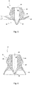
- FIG. 2 shows the combination valve 17 in a state in which it is not installed.
- the umbrella section 20 is already preformed with the manufacture of the combination valve 17 so that it is not flat and plate-shaped, but funnel-shaped and thus shaped like an umbrella and at least partially encloses the base section 19 of the base body 18 of the combination valve 17 on the outside.
- the screen section 20 has a circumferential angle of inclination a, which causes a pre-shaping of the screen section 20, which is formed opposite to the later installation direction of extension of the screen section 20. If the combination valve 17 is inserted into the valve tube 12, the umbrella section 20 turns inside out. In particular, it can be provided that the screen section 20 extends at an angle of more than 90 °, e.g. B.
- FIG Figure 3 shows the combination valve 17 with the base section 19 and with the umbrella section 20 in a state that is approximately assumed when the combination valve 17 is installed and rests on the inside against the wall of the valve tube 12, as in FIG Figure 1 shown.
- the umbrella section 20 is turned inside out in such a way that it extends around the central axis 25 in the direction of the opening side of the bill valve 21, for example in the manner of a sleeve or a pipe section.
- the inclination of the shield section 20 with the angle of inclination a shown in the base body 18 results in a good contact of the shield section 20 on the wall of the valve tube, which has a positive effect on the valve action against the opening in the wall of the valve tube.
- the base section 19 On the side facing away from the bill valve 21, the base section 19 has a mounting cone 40 on the outside circumference in order to insert the base body 18 of the combination valve 17 into the opening of the receiving collar in the valve tube, as shown in FIG Figure 1 shown. That's how it works The combination valve 17 is particularly easy to insert into the valve tube as part of the assembly of the foam pump 1.
- the beak valve and the flutter valve do not necessarily have to be designed as a one-piece combination valve. Rather, they can also be designed in the form of two separately designed components which are each received in the valve tube.
- a turbulence unit is not absolutely necessary. Rather, foam generators can be connected directly to the mixing chamber. As in Figure 1 shown, be arranged in an output-side section of the actuation unit 41. However, these can be arranged differently in the actuation unit 41, e.g. B. both in a section opposite the output end above the actuation plate 37. Furthermore, other functional units can be arranged in the actuation unit 41. For example, an insert or a shape in the form of a constriction can be provided in the area of the dispensing end, whereby, for example, a better tear-off of the dispensed foam can be achieved.
- FIG. 4 a further embodiment of the foam pump 1 according to the invention is shown in a cross-sectional view.
- the structure of the foam pump 1 is similar to that in FIG Figure 1 foam pump shown. However, there are differences in particular in the area of the combination valve 17 and the actuation unit 41.
- the combination valve 17, which is in the Figures 5 and 6 is shown again individually, differs from the embodiment according to FIG Figures 1 to 3 Essentially in that the umbrella section 20 is kept somewhat shorter and, in the installed state, is turned inside out less strongly, whereby a good valve effect of the flutter valve 24 formed with the umbrella section 20 can also be achieved with this less pronounced eversion.
- the screen portion 20 does not directly cover the openings 22 in the wall 23 of the valve tube 12.
- the screen section 20 does not lie flat against the wall 23 around the openings 22. Rather, the shield section 20 lies sealingly against the wall 23 of the valve tube 12 in an area spaced apart from the openings 22. This is also sufficient to be able to selectively establish or close the fluidic connection between the air chamber 14 and the mixing chamber 16.
Landscapes
- Health & Medical Sciences (AREA)
- Public Health (AREA)
- Reciprocating Pumps (AREA)
- Containers And Packaging Bodies Having A Special Means To Remove Contents (AREA)
- Closures For Containers (AREA)
Abstract
Description
- Die Erfindung betrifft eine Schaumpumpe zur Anordnung an einen mit Flüssigkeit gefüllten Behälter mit den Merkmalen des Oberbegriffs von Anspruch 1.
- Schaumpumpen sind aus dem Stand der Technik in vielfacher Ausführung bekannt und werden dazu verwendet, aus einem aufschäumbaren flüssigen Medium, also beispielsweise eine Flüssigseife oder eine aufschäumbare Desinfektionslösung, durch Vermischung mit Luft einen Schaum herzustellen, der bei Betätigung der Schaumpumpe beispielsweise in eine Hand eines Benutzers ausgegeben werden kann. Dabei sind Schaumpumpen bekannt, die Flüssigkeit aus einem flexiblen Behälter, also beispielsweise aus einem Beutel, entnehmen können. Daneben sind Schaumpumpen bekannt, die Flüssigkeit aus einem formstabilen Behälter saugen können und diesen damit evakuieren.
- Eine nicht evakuierende Schaumpumpe ist beispielsweise aus dem Dokument
EP 2 127 756 A1 bekannt. Die Schaumpumpe weist eine Mischkammer auf, in die bei Betätigung aus einem Pumpenbalg Luft durch ein Schnabelventil eingegeben werden kann. Aus dem Behälter läuft nach einem Pumpvorgang die Flüssigkeit schwerkraftbedingt aus einem oberhalb der Mischkammer angeordneten Behälter wieder in die Mischkammer nach. - Evakuierende Schaumpumpen sind meist entweder für die Ausgabe von Schaumseife oder für die Ausgabe von Schaumdesinfektionsmittel konzipiert. Universell einsetzbare Schaumpumpen, die sowohl eine Schaumseife als auch Schaumdesinfektionsmittel pumpen oder saugen können, weisen einen demgegenüber komplexen Aufbau auf und sie enthalten Bauteile, die eine einfache Entsorgung nicht möglich machen. Z. B. werden in derartigen Schaumpumpen Metallfedern oder Glaskugeln als Spannelemente und Rückschlagventile eingesetzt.
- In dem Dokument
EP 3 085 456 B1 ist eine gattungsgemäße Schaumpumpe zur Anordnung an einen mit Flüssigkeit gefüllten Behälter offenbart. Die Schaumpumpe umfasst einen Ventilträger, in dem ein Einlassventil aufgenommen ist, sowie ein Ventilrohr, das unter Veränderung eines Volumens in einer Pumpkammer hubbeweglich im Ventilträger aufgenommen ist. Infolge einer Hubbewegung des Ventilrohrs relativ zu dem Ventilträger wird Flüssigkeit aus dem Behälter durch das Einlassventil in die Pumpkammer überführt. Weiter weist die Schaumpumpe einen Pumpenbalg mit einer Luftkammer auf, aus der bei einer Hubbewegung des Ventilrohres Luft in eine Mischkammer überströmen kann. In der Mischkammer wird die Luft mit der Flüssigkeit vermengt. Darauffolgend sind Schaumsiebe zum Verschäumen der Flüssigkeit angeordnet. - Die bekannte Schaumpumpe ist nachteilhafterweise nicht universell einsetzbar und aufwändig und komplex in der Montage. Zudem hat sich gezeigt, dass die Schaumqualität der Schaumpumpe für nur im Wesentlichen eine Art von Flüssigkeit zufriedenstellend ist. Darüber hinaus weist die Schaumpumpe eine Vielzahl von miteinander zu montierenden Einzelteilen auf.
- Es ist die Aufgabe der Erfindung, eine Schaumpumpe derart weiterzubilden, dass diese einfach zu entsorgen ist, ohne dass eine aufwändige Demontage erforderlich ist. Weiter soll die Schaumpumpe für verschiedene Arten von aufschäumbaren Flüssigkeiten einsetzbar sein, beispielsweise für Schaumseife und für eine Schaumdesinfektionslösung, insbesondere sollte die Schaumpumpe einen Behälter zur Bereitstellung der Flüssigkeit evakuieren können.
- Diese Aufgabe wird ausgehend von einer Schaumpumpe gemäß dem Oberbegriff von Anspruch 1 in Verbindung mit den kennzeichnenden Merkmalen gelöst. Vorteilhafte Weiterbildungen der Erfindung sind in den abhängigen Ansprüchen angegeben.
- Die Erfindung sieht zur Lösung der vorstehend aufgeführten Aufgabe vor, dass zwischen der Pumpkammer und der Mischkammer ein Schnabelventil angeordnet ist, durch das bei einer Hubbewegung des Ventilrohres relativ zu dem Ventilträger Flüssigkeit aus der Pumpkammer in die Mischkammer überströmbar ist, und dass zwischen der Luftkammer und der Mischkammer ein Flatterventil angeordnet ist, durch das bei einer Hubbewegung des Ventilrohres relativ zu dem Ventilträger Luft aus der Luftkammer im Pumpenbalg in die Mischkammer überströmbar ist.
- In diesem Zusammenhang bedeutet der Begriff "zwischen" nicht zwingend "räumlich zwischen". D. h. das Schnabelventil muss nicht räumlich unmittelbar zwischen der Pumpkammer und der Mischkammer angeordnet sein. Vielmehr ist mit dem Begriff "zwischen" gemeint, dass das Schnabelventil in Hinblick auf die fluidische Verbindung zwischen der Pumpkammer und der Mischkammer angeordnet ist. Dies gilt entsprechend für das Flatterventil und dessen Anordnung zwischen der Luftkammer und der Mischkammer.
- Kerngedanke der Erfindung ist eine vorteilhafte Ventilkombination aus einem Schnabelventil und einem Flatterventil, wobei über das Schnabelventil Flüssigkeit aus der Pumpkammer in die Mischkammer gelangen kann, das aber den Übergang von Flüssigkeit von der Mischkammer zurück in die Pumpkammer sperrt. Zugleich bildet das Flatterventil auf einfache Weise ein Ventil für ein gasförmiges Medium.
- Das Flatterventil und das Schnabelventil sind erfindungsgemäß so ausgebildet und angeordnet, dass diese im Zuge einer Hubbewegung, mit der sich das Volumen der Pumpkammer verkleinert und gleichzeitig auch das Volumen der Luftkammer verkleinert, in ihre Öffnungsstellung überführt werden. In der Öffnungsstellung kann einerseits Flüssigkeit aus der Pumpkammer und von dort in die Mischkammer gefördert werden und andererseits kann Luft aus der Luftkammer in die Mischkammer gefördert werden. D. h. es gelangen gleichzeitig Flüssigkeit und Luft in die Mischkammer, in der sie vermischt werden. Bei der umgekehrten Hubbewegung, mit der sich das Volumen der Pumpkammer vergrößert und mit der sich auch der Pumpenbalg wieder entspannt, so dass sich das Volumen der Luftkammer vergrößert, schließen sowohl das Flatterventil als auch das Schnabelventil. So kann wirksam verhindert werden, dass Flüssigkeit und/oder Schaum von der Mischkammer in die Luftkammer gelangen, was zu einer dauerhaften Verunreinigung des Pumpenbalgs und der darin gebildeten Luftkammer führen würde. Auch kann so die Gefahr eines Übertritts von Luft bzw. dem Flüssigkeit-Luft-Gemisch von der Mischkammer in die Pumpkammer minimiert werden, der langfristig die evakuierende Wirkung der Schaumpumpe beeinträchtigen würde.
- Im Ergebnis wird eine einfach ausgeführte Schaumpumpe gebildet, die durch die Veränderlichkeit des Volumens der Pumpkammer in Verbindung mit dem Einlassventil einen Behälter zur Bereitstellung der aufzuschäumenden Flüssigkeit evakuieren kann. Die gute Dichtwirkung, die bei der erfindungsgemäßen Schaumpumpe erreicht werden kann, ist dabei nicht nur für die evakuierende Wirkung wichtig. Vielmehr wird durch die gute Dichtwirkung auch sichergestellt, dass die Flüssigkeit und der Schaum jeweils nur in Förderrichtung strömen können, aber nicht in umgekehrter Richtung. Insbesondere kann auch effektiv verhindert werden, dass Verunreinigungen von außen in die Schaumpumpe bzw. den Behälter gelangen, welche andernfalls im schlimmsten Fall sogar zu einer Verkeimung führen könnten. Zudem zeichnet sich die erfindungsgemäße Schaumpumpe dadurch aus, dass aufgrund der gleichartig wählbaren Materialien der Bestandteile der Schaumpumpe aus dem Bereich der Kunststoffe die Schaumpumpe ohne Materialauftrennungen entsorgt werden kann.
- Vorteilhafterweise ist das Schnabelventil und/oder das Flatterventil im Ventilrohr aufgenommen, womit ein kompakter Aufbau realisiert werden kann.
- Die gewünschte Ventilwirkung des Flatterventils kann auf einfache Weise erreicht werden, wenn das Flatterventil an der Innenseite der Wand des Ventilrohres anliegend angeordnet ist. Insbesondere kann vorgesehen sein, dass das Flatterventil vollumfänglich an der z. B. als Zylindermantel ausgeführten Innenwand des Ventilrohrs anliegt. Mittels einer Öffnung in der Wand des Ventilrohres kann - abhängig von der Ventilstellung des Flatterventils - Luft in den Innenraum des Ventilrohres einströmen, in dem unmittelbar die Mischkammer ausgebildet sein kann. Statt einer Öffnung können auch mehrere Öffnungen über den Umfang des Ventilrohres verteilt in der Wand eingebracht sein, die von dem Flatterventil selektiv geöffnet und verschlossen werden. Das Flatterventil kann dabei so ausgebildet sein, dass dieses die Öffnungen unmittelbar abdeckt. Es kann aber auch vorgesehen sein, dass das Flatterventil die Öffnungen nicht oder zumindest nicht vollständig abdeckt. Die abdichtende Wirkung des Flatterventils kann in diesem Fall dadurch erreicht werden, dass es in seiner geschlossenen Stellung dichtend an der Innenwand anliegt und so die Luftkammer von der Mischkammer trennt.
- Gemäß einer erfindungsgemäßen Ausführungsform sind das Schnabelventil und das Flatterventil als Kombinationsventil mit einem baueinheitlichen und einstückigen Grundkörper ausgebildet. So lässt sich ein besonders einfacher Aufbau mit geringem Montageaufwand realisieren. Das Kombinationsventil kann dabei mit dem Grundkörper im Ventilrohr eingesetzt sein.
- Der Grundkörper des Kombinationsventils ist vorzugsweise so ausgeführt, dass dieser einen Sockelabschnitt und einen Schirmabschnitt aufweist, wobei der Schirmabschnitt außenumfänglich am Sockelabschnitt angeformt ist und diesen umlaufend überragt. Z. B. kann das Flatterventil von dem Schirmabschnitt ausgebildet sein, während das Schnabelventil im Bereich des Sockelabschnitts ausgebildet ist.
- Konkret können in der Wand des Ventilrohres auf der Höhe des innenseitig anliegenden Schirmabschnittes eine oder mehrere Öffnungen vorhanden sein, die in der geschlossenen Stellung des Flatterventils durch den Schirmabschnitt abgedeckt sind und/oder deren fluidische Verbindung mit der Mischkammer durch den Schirmabschnitt verschlossen ist. Wird der Pumpenbalg durch Betätigung der Schaumpumpe komprimiert, steigt der Druck in der Luftkammer des Pumpenbalgs über den Druck in der Mischkammer. Bei Überschreiten einer vorgegebenen Druckdifferenz hebt der Schirmabschnitt zumindest kurzzeitig von der Innenwand ab, so dass Luft von der Luftkammer durch die Öffnung in die z. B. innerhalb des Ventilrohres gebildete Mischkammer gelangt. Wird die Druckdifferenz wieder unterschritten, verformt sich der Schirmabschnitt zurück und liegt wieder an der Innenwand an, d. h. das Flatterventil ist wieder geschlossen. Folglich wird eine Rückströmung von Luft von der Mischkammer zurück in die Luftkammer des Pumpenbalges mit dem so gebildeten Flatterventil verhindert. Das Flatterventil kann auch als Lamellenventil bezeichnet werden.
- Das Kombinationsventil ist vorzugsweise so ausgeführt, dass der Schirmabschnitt im nicht eingebauten Zustand kragenförmig oder trichterförmig geformt ist und den Sockelabschnitt - zumindest im nicht eingebauten Zustand - überdacht oder umschließt. Das Umschließen des Sockelabschnittes erfolgt dabei vorzugsweise etwa schirmartig und ggf. mit einem entsprechenden Abstand zwischen dem Schirmabschnitt und dem Sockelabschnitt. Insbesondere kann der Schirmabschnitt einen nach unten geneigten Kragen in Richtung zum freien Ende des Sockelabschnittes bilden. So kann erreicht werden, dass - wenn das Kombinationsventil eingebaut wird - der Schirmabschnitt in gewisser Weise vom Sockelabschnitt weg nach oben abgestreckt wird, sodass der Schirmabschnitt vom nicht eingebauten Zustand in den eingebauten Zustand entlang einer Mittelachse um einen vorgegebenen Winkel umgestülpt wird. Dadurch kann erreicht werden, dass der Schirmabschnitt mit einer vorgegebenen Vorspannung gegen die Innenwand des Ventilrohrs anliegt. Durch diese Vorspannung ist in gewisser Weise die Druckdifferenz vorgegeben, die überschritten werden muss, um das Flatterventil in seine Öffnungsstellung zu überführen. Beispielsweise kann das Kombinationsventil so ausgebildet sein, dass bei dessen Einbau der Schirmabschnitt um einen Winkel von mehr als 20° und insbesondere von mehr als 90° entlang der Mittelachse umgestülpt wird. Dadurch ergibt sich eine besonders sichere Anlage des Schirmabschnittes gegen die Innenseite des Ventilrohres, sodass es zu einer besonders guten Ventilwirkung des Schirmabschnittes gegenüber der Öffnung in der Wand des Ventilrohres kommt. Es reicht aber auch aus, wenn der Schirmabschnitt um einen kleineren Winkel umgestülpt wird, um eine gute Ventilwirkung zu erreichen.
- Im Bereich des Sockelabschnitts des Kombinationsventils kann ein Fluidkanal vorgesehen sein, der sich insbesondere entlang der Mittelachse erstreckt und in das Schnabelventil des Kombinationsventils mündet. Durch diesen Fluidkanal kann in der Öffnungsstellung des Schnabelventils die Flüssigkeit aus der Pumpkammer in die Mischkammer strömen.
- Mit weiterem Vorteil ist das Kombinationsventil oder zumindest dessen Grundkörper aus einem Kunststoff, z. B. Silikon, ausgebildet. Insbesondere lässt sich das Kombinationsventil so auf einfache Weise und kostengünstig herstellen, wobei gleichzeitig eine gute Ventilwirkung erreicht wird. Außerdem zeichnet sich insbesondere Silikon durch eine hohe Medienbeständigkeit aus.
- Wie bereits erwähnt, kann die Mischkammer unmittelbar in dem Ventilrohr ausgebildet sein. Alternativ oder zusätzlich kann die Pumpkammer im Ventilrohr ausgebildet sein.
- In weiterer Ausgestaltung kann der Ventilträger einen Kolbenabschnitt aufweisen, der sich in das Ventilrohr hinein erstreckt, sodass der Kolbenabschnitt bei einer Hubbewegung des Ventilrohres das Volumen in der Pumpkammer verändert. Der Kolbenabschnitt kann einzeln ausgeführt sein oder der Kolbenabschnitt bildet einen Abschnitt des Ventilträgers, der insbesondere einstückig und materialeinheitlich mit dem Ventilträger ausgebildet sein kann. Konkret kann der Kolbenabschnitt zylinderförmig ausgeführt sein und mit seiner Außenumfangsfläche an der Innenseite des Ventilrohres dichtend anliegen. Um eine Hubbewegung des Ventilrohrs relativ zu dem Ventilträger zu führen, kann das Ventilrohr mit einem endseitigen Abschnitt auf der Außenumfangsfläche des Kolbenabschnittes flüssigkeitsdichtend geführt sein, wobei die Flüssigkeit eine Schmierwirkung zwischen der Außenumfangsfläche des Kolbenabschnitts und der Innenseite des Ventilrohres erfüllen kann.
- Mit besonderem Vorteil ist das Einlassventil an dem Ventilträger und insbesondere ebenfalls im Kolbenabschnitt angeordnet. Beispielsweise ist das Einlassventil kopfseitig im Kolbenabschnitt angeordnet und weist einen Ventilteller auf, der eine Überströmöffnung im Kolbenabschnitt überdeckt. Wird das Ventilrohr nach einer Betätigung der Schaumpumpe in seine Ausgangsposition relativ zu dem Ventilträger zurückgeführt, vergrößert sich das Volumen der Pumpkammer, wodurch Flüssigkeit über das Einlassventil in die Pumpkammer gezogen wird. Dafür hebt sich z. B. der Ventilteller von der Überströmöffnung ab, wodurch Flüssigkeit aus dem Behälter in die Pumpkammer nachströmen kann. Die Rückführung des Ventilrohres in seine Ausgangsposition relativ zum Ventilträger kann durch die elastische Wirkung des Pumpbalges erfolgen und/oder durch externe Federmittel, die z. B. in einer Aufnahmevorrichtung der Schaumpumpe vorhanden sein können.
- Das Kombinationsventil ist vorzugsweise im Ventilrohr selbst aufgenommen und es kann mit der Hubbewegung des Ventilrohres mitbewegt werden. Zur Aufnahme des Kombinationsventils im Ventilrohr kann das Ventilrohr einen nach innen weisenden Aufnahmekragen aufweisen, an dem das Kombinationsventil aufgenommen ist und wodurch dieses innerhalb des Ventilrohres die Pumpkammer von der Mischkammer trennt. Insbesondere kann so eine einfache Montage und gleichzeitig ein kompakter Aufbau der Schaumpumpe erreicht werden.
- Mit weiterem Vorteil weist der Pumpenbalg einen Stutzen auf, der einen Abschnitt des Ventilrohres außenseitig umschließt, wobei in diesem Bereich wenigstens ein Lufteinlasskanal gebildet ist, durch den Luft in die Luftkammer des Pumpenbalges überströmbar ist.
- Die Betätigung der Schaumpumpe kann mittels einer Betätigungseinheit erfolgen. Diese kann einen Betätigungsteller aufweisen, der direkt manuell betätigt werden kann oder indirekt durch eine manuelle Aktivierung eines weiteren externen Bauteils in einer Aufnahmevorrichtung für den Behälter mit der Schaumpumpe betätigt werden kann, wodurch ein jeweiliger Pumpzyklus ausgelöst wird. Die Betätigungseinheit kann einen hülsenartig geformten Abschnitt aufweisen, mit dem eine Bewegung der Betätigungseinheit entlang dem Ventilrohr und/oder dem Stutzen des Pumpenbalgs geführt wird. Z. B. kann der hülsenartig geformte Abschnitt so in dem Ventilrohr eingesteckt sein, dass die Betätigungseinheit um einen vorgegebenen Weg relativ zu dem Ventilrohr bewegt werden kann. Das Luft-Flüssigkeits-Gemisch kann dabei durch einen Fluidkanal der Betätigungseinheit von der Mischkammer zu einem Ausgabeende gelangen.
- Um den Pumpzyklus auszulösen, ist die Betätigungseinheit mit dem Pumpenbalg derart gekoppelt, dass der Pumpenbalg bei einer der Betätigung der Betätigungseinheit komprimiert wird. Entspannt sich der Pumpenbalg wieder und wird er (durch elastische Rückstellkräfte oder Federkräfte von externen Federmitteln) wieder in seine Ausgangsposition zurückgeführt, wird auch die Betätigungseinheit wieder in ihre unbetätigte Stellung zurückgeführt. Konkret kann die Betätigungseinheit hierzu an dem Stutzen des Pumpenbalgs verankert sein, wobei die Betätigungseinheit mittels eines Absatzes, der z. B. durch den Betätigungsteller gebildet sein kann, den Pumpenbalg in seine komprimierte Stellung drückt. Dabei kann ein Teil des Wegs, der zurückgelegt wird, dazu dienen, eine zwischen dem Stutzen und dem Absatz bzw. Betätigungsteller gebildete Lufteinlassöffnung zu schließen, durch die Luft von außen in die Luftkammer des Pumpenbalgs strömen kann.
- Für die Erreichung einer guten Schaumqualität kann sich an die Mischkammer zumindest ein Schaumgenerator anschließen, der wenigstens zwei, drei, vier oder mehr als vier Schaumsiebe aufweist. Z. B. kann der Schaumgenerator mit den mehreren Schaumsieben in einem sich an die Mischkammer anschließenden Ausgabeende des Ventilrohres oder im Bereich der Betätigungseinheit angeordnet sein. Wird die Flüssigkeit mit der Luft in der Mischkammer vorgemischt und durch die Schaumsiebe gedrückt, beispielsweise Mikrometer-Maschensiebe, so erzeugen die Siebe insbesondere in ihrer zueinander beabstandeten Anordnung hintereinander einen sehr formstabilen Schaum, was insbesondere begünstigt wird durch die mehreren hintereinander angeordneten Schaumsiebe mit dazwischen ausgebildeten Zwischenräumen. Im Ergebnis ergibt sich damit ein besonders formfester Schaum, insbesondere unabhängig von der Art der Flüssigkeit, die in die Schaumpumpe eingegeben wird.
- Weitere, die Erfindung verbessernde Maßnahmen werden nachstehend gemeinsam mit der Beschreibung bevorzugter Ausführungsbeispiele der Erfindung anhand der Figuren näher dargestellt. Es zeigt:
- Figur 1
- eine Ausführungsform einer erfindungsgemäßen Schaumpumpe in einer Querschnittsansicht,
- Figur 2
- eine Ausführungsform eines erfindungsgemäßen Kombinationsventils im nicht eingebauten Zustand,
- Figur 3
- das Kombinationsventil gemäß
Figur 2 im eingebauten Zustand - Figur 4
- eine Ausführungsform einer erfindungsgemäßen Schaumpumpe in einer Querschnittsansicht,
- Figur 5
- eine Ausführungsform eines erfindungsgemäßen Kombinationsventils im nicht eingebauten Zustand,
- Figur 6
- das Kombinationsventil gemäß
Figur 5 im eingebauten Zustand. -
Figur 1 zeigt in einer quergeschnittenen Ansicht ein Ausführungsbeispiel einer erfindungsgemäßen Schaumpumpe 1. Die Schaumpumpe 1 weist einen Ventilträger 10 auf. Der Ventilträger kann z. B. als Spritzguss-Kunststoffbauteil hergestellt sein. Der Ventilträger 10 ist so ausgebildet, dass dieser an einen inFigur 1 nicht dargestellten Behälter, in dem sich eine Flüssigkeit wie eine Schaumseife oder eine aufschäumbare Desinfektionslösung befindet, angeordnet werden kann. - Bei dem in
Figur 1 dargestellten Ausführungsbeispiel ist der Ventilträger 10 und damit auch die Schaumpumpe 1 so ausgebildet, dass die Verbindung mit dem Behälter mittels einer Schraubverbindung erfolgt. Hierzu weist der Ventilträger 10 ein Innengewinde 38 auf, über welches die Schaumpumpe 1 z. B. an einen Ausgabestutzen des Behälters angeschraubt werden kann. In dem von dem Innengewinde 38 umschlossenen Bereich befinden sich Zuleitungen zu einem Ventilsystem, zu dem die Seife oder die Lösung fließen kann. Das Innengewinde des Ventilträgers 10 kann dabei dicht mit einem an dem Behälter ausgebildeten Gegenwinde abschließen. Bei dem inFigur 1 gezeigten Ausführungsbeispiel wird die abdichtende Wirkung jedoch durch einen an dem Ventilträger 10 ausgebildeten Dichtkonus 43 erreicht, der dichtend an einem Hals des Behälters anliegen kann. - Um seine zentrale Mittelachse 25 herum weist der Ventilträger 10 einen Kolbenabschnitt 27 auf, der einen starren Abschnitt des Ventilträgers 10 innerhalb des Innengewindes 38 bildet. Der Kolbenabschnitt 27 weist eine plane Stirnseite mit einer Überströmöffnung 36 auf, durch die Flüssigkeit aus dem Behälter in eine sich anschließende Pumpkammer 14 treten kann. An der Stirnseite ist ein Einlassventil 11 befestigt, welches einen Ventilteller 35 aufweist, der im Ruhezustand die Überströmöffnung 36 abdeckt.
- Die Pumpkammer 14 ist von einem Ventilrohr 12 ausgebildet. Das Ventilrohr 12 ist auf eine zylindrische Außenumfangsfläche des Kolbenabschnittes 27 aufgeschoben und entlang der Mittelachse 25 axial beweglich auf dem Kolbenabschnitt 27 geführt. Wird das Ventilrohr 12 in Richtung der Mittelachse 25 axial auf und ab bewegt, so schiebt sich ein Endabschnitt des Ventilrohres 12 unterschiedlich weit über den Kolbenabschnitt 27, was zu einer Änderung des Volumens der Pumpkammer 13 führt. Wird durch eine Betätigung der Schaumpumpe 1 das Ventilrohr 12 weiter auf den Kolbenabschnitt 27 aufgeschoben, verkleinert sich das Volumen der Pumpkammer 13. Bei einer Rückführbewegung des Ventilrohres 12 relativ zu dem Ventilträger 10 wandert der Kolbenabschnitt 27 wieder aus dem Ventilrohr 12 heraus und das Volumen der Pumpkammer 13 vergrößert sich. Eine Vergrößerung des Volumens der Pumpkammer 13 bewirkt dabei einen Unterdruck in der Pumpkammer 13 gegenüber dem Behälter, wodurch das Einlassventil 11 in seine Öffnungsstellung überführt wird und Flüssigkeit aus dem Behälter durch die Überströmöffnung 36 in die Pumpkammer 13 strömen kann.
- Nachfolgend an die Pumpkammer 13 befindet sich eine Mischkammer 16, die durch ein in dem Ventilrohr 12 eingesetztes Kombinationsventil 17 von der Pumpkammer 13 separiert ist. Das Kombinationsventil 17 ist dabei über einen Aufnahmekragen 28 innerhalb des Ventilrohres 12 fest aufgenommen. Das Kombinationsventil 17 weist einen Grundkörper 18 mit einem Sockelabschnitt 19 und einen sich daran anschließenden Schirmabschnitt 20 auf. Zentral durch den Sockelabschnitt 19 erstreckt sich ein Fluidkanal 26, der in ein Schnabelventil 21 mündet. Der Schirmabschnitt 20 des Kombinationsventils liegt im eingebauten Zustand gegen eine Innenwand des Ventilrohres 12 an und überdeckt Öffnungen 22, die in diesem Bereich in der Wand 23 des Ventilrohres 12 vorgesehen sind.
- Wird durch eine Betätigung der Schaumpumpe 1 das Ventilrohr 12 in Richtung des Kolbenabschnittes 27 bewegt, verringert sich das Volumen der Pumpkammer 13. Durch den entstehenden Überdruck in der Pumpkammer 13 wird zum einen sichergestellt, dass das Einlassventil 11 sicher geschlossen ist und somit keine Flüssigkeit aus dem Behälter in die Pumpkammer 13 strömen kann. Zum anderen wird durch den in der Pumpkammer 13 entstehenden Überdruck das Schnabelventil 21 in seine Öffnungsstellung überführt, so dass Flüssigkeit durch den Fluidkanal 26 und das Schnabelventil 21 in die Mischkammer 16 strömen kann.
- Weiter weist die Schaumpumpe 1 einen Pumpenbalg 15 auf. Der Pumpenbalg 15 weist an seiner einen Stirnseite einen Aufnahmekragen zur Verbindung mit dem Ventilträger 10 auf. An seiner anderen Stirnseite weist er einen Stutzen 33 auf, mittels dem der Pumpenbalg 15 mit dem Ventilrohr 12 verbunden ist. Dazwischen bildet der Pumpenbalg 15 eine Luftkammer 14 aus. Diese wird an ihrem Außenumfang von mehreren zylinderartigen Balgabschnitten mit abgestuft kleiner werdendem Durchmesser begrenzt. An ihrem Innenumfang wird diese von der Wand 23 des Ventilrohrs 12 begrenzt.
- Wenn die Schaumpumpe 1 betätigt wird und das Ventilrohr 12 auf den Kolbenabschnitt 27 aufgeschoben wird, wird der Stutzen 33 des Pumpenbalgs 15 mitgeführt und in Richtung des Ventilträgers 10 verschoben. Dadurch verringert sich zum einen das Volumen der Luftkammer 14. Zum anderen wird durch die elastische Verformung des Pumpenbalgs 15 eine Rückstellkraft bewirkt, durch die der Pumpenbalg 15 das Ventilrohr 12 nach einer Betätigung in seine Ausgangslage zurückführt, in der der Kolbenabschnitt 27 wieder nur um ein kleineres Stück in das Ventilrohr 12 eintaucht. Die elastische Rückfederung kann dabei durch externe, in
Figur 1 nicht dargestellte Federmittel unterstützt sein. - Die Luftkammer 14 des Pumpenbalgs 15 ist mit der in dem Ventilrohr 12 ausgebildeten Mischkammer 16 fluidisch verbunden und zwar über die Öffnungen 22 in der Wand 23 des Ventilrohrs 12, welche im Bereich der Mischkammer 26 vorgesehen und durch den Schirmabschnitt 20 des Kombinationsventils abgedeckt sind. Der Schirmabschnitt 20 bildet dabei ein Flatterventil aus, über das selektiv Luft von der Luftkammer 14 in die Mischkammer 16 überströmen kann.
- Die Funktionsweise ist dabei wie folgt: Wird die Schaumpumpe 1 betätigt, strömt - wie bereits voranstehend erläutert - Flüssigkeit durch das Schnabelventil 21 in die Mischkammer 16. Gleichzeitig wird der Pumpenbalg 15 zusammengedrückt, wodurch sich das Volumen der Luftkammer 14 verringert und entsprechend der Luftdruck in der Luftkammer 14 steigt. Überschreitet der Druck in der Luftkammer 14 den Druck in der Mischkammer 16 hebt sich der Schirmabschnitt 20 bereichsweise von der Innenseite der Wand 23 des Ventilrohres 12 ab, so dass Luft durch die Öffnungen 22 in die Mischkammer 16 strömen kann. So kann der Flüssigkeit aus der Pumpkammer 13 Luft zugemischt werden, welche in der Mischkammer 16 vorgemischt und ggf. auch vorgeschäumt werden.
- An die Mischkammer 16 schließen sich in Richtung der Mittelachse 25 gesehen eine Verwirbelungseinheit 32 und zwei Schaumgeneratoren 30 an, welche beispielhaft jeweils zwei Schaumsiebe 31 aufweisen, an. Die beiden Schaumgeneratoren 30 sind als Hülsenkörper ausgeführt und weisen planseitig die flächigen Schaumsiebe 31 auf, sodass bei beabstandet zueinander angeordneten Schaumgeneratoren 30 insgesamt vier Schaumsiebe 31 auf den Schaumkanal nach der Mischkammer 16 folgen, um aus dem Flüssigkeits-Luft-Gemisch einen möglichst feinen Schaum zu erzeugen. Die Schaumsiebe 31 bilden vorzugsweise Mikrometersiebe, z. B. mit einer Maschengröße im Bereich von 100 µm.
- Dabei hat sich gezeigt, dass die Anordnung von vier Schaumsieben 31 mit jeweiligen Abständen zwischen diesen einen besonders hochwertigen Schaum erzeugen können, der formstabil ist. Insbesondere kann auch bei verschiedenen Arten von Flüssigkeiten, die über das Ventilrohr 12 zugeführt werden, ein qualitativ hochwertiger Schaum erzeugt werden.
- Die Verwirbelungseinheit 32 und die beiden Schaumgeneratoren 30 sind jeweils in einem hülsenartig geformten Abschnitt einer Betätigungseinheit 41 angeordnet. Zwischen den beiden hülsenartigen Abschnitten weist die Betätigungseinheit 41 einen Betätigungsteller 37 auf, über den die Schaumpumpe 1 betätigt werden kann. Dazu kann die Schaumpumpe 1 beispielsweise in eine entsprechende Vorrichtung eingesetzt sein, wobei durch eine manuelle Aktivierung eines weiteren externen Bauteils in der Aufnahmevorrichtung der Betätigungsteller 37 auf und ab bewegt werden, wodurch ein jeweiliger Pumpzyklus ausgelöst wird.
- Der eine hülsenartige Abschnitt der Betätigungseinheit 41, in dem bei dem in
Figur 1 gezeigten Ausführungsbeispiel die Verwirbelungseinheit 32 angeordnet ist, erstreckt sich durch den Stutzen 33 des Pumpenbalgs 15 bis in das Ventilrohr 12 hinein. Dabei ist die Betätigungseinheit 41 zumindest in begrenzten Umfang in dem Ventilrohr 12 in Richtung der Mittelachse 25 verschieblich geführt. Begrenzt wird der Verschiebefreiheitsgrad durch an der Betätigungseinheit 41 bzw. dem Stutzen 33 gebildete Anschläge: - In Betätigungsrichtung der Schaumpumpe 1 kann die Betätigungseinheit 41 in das Ventilrohr 12 hinein geschoben werden bis der Betätigungsteller bzw. ein daran angeformter Absatz dichtend an der Stirnseite des Stutzens 33 anliegt. Insbesondere wird dann ein Lufteinlasskanal 34 im Bereich zwischen dem Stutzen 33 und der Betätigungseinheit 41 bzw. dem Ventilrohr 12 luftdicht verschlossen.
- In umgekehrter Richtung wird der Verschiebefreiheitgrad dadurch begrenzt, dass sich die Betätigungseinheit 41 nur so weit aus der Ventilrohr 12 herausbewegen kann, bis ein am Außenumfang der Betätigungseinheit 41 ausgebildeter Anschlag an einen am Innenumfang des Stutzens 33 gebildeter Gegenanschlag anliegt. In dieser Position ist der Lufteinlasskanal 34 geöffnet, so dass Luft von einem Bereich unterhalb des Betätigungstellers 37 in die Luftkammer 14 des Pumpenbalgs 15 überströmen kann.
- Um einem Austritt von Schaum aus der Mischkammer 16 vorzubeugen, sind an dem hülsenartigen Abschnitt der Betätigungseinheit 41, mit dem sich dieser in das Ventilrohr 12 hinein erstreckt, bei dem in
Figur 1 gezeigten Ausführungsbeispiel drei Dichtrillen am Außenumfang dieses Abschnitts vorgesehen. Die dichtende Wirkung kann jedoch auch mit mehr oder weniger Dichtrillen oder mit separaten Dichtmitteln, wie einem O-Ring o. ä., erreicht werden. - Die Schaumerzeugung soll im Folgenden noch einmal näher erläutert werden:
Bei jeder Pumpbewegung verkleinert und vergrößert sich anschließend wieder das Volumen in der Pumpkammer 13 durch die Rückführbewegung des Ventilrohres 12 aufgrund der elastischen Rückformung des Pumpenbalgs 15 bzw. aufgrund der Federkräfte von externen Federmitteln. - Wenn sich das Volumen in der Pumpkammer 13 vergrößert, wird infolge des darin herrschenden Unterdrucks das Einlassventil 11 in seine Öffnungsstellung überführt. D. h. der Ventilteller 36 hebt von der Überströmöffnung 36 ab und es kann Flüssigkeit durch die Überströmöffnung 36 in die Pumpkammer 13 nachgezogen werden. Zugleich schließt das Schnabelventil 21 des Kombinationsventils 17. D. h. es wird verhindert, dass Flüssigkeit bzw. ein Luft-Flüssigkeit-Gemisch aus der Mischkammer 16 in die Pumpkammer 13 gesogen wird. Außerdem schließt während dieser Bewegung das Flatterventil 24 aufgrund des in dem Pumpenbalg 15 herrschenden Unterdrucks, wodurch verhindert wird, dass Flüssigkeit bzw. ein Luft-Flüssigkeit-Gemisch aus der Mischkammer 16 in die Luftkammer 14 gesogen wird. Aufgrund des Unterdrucks in der Luftkammer 14 wird jedoch durch den dann geöffneten Lufteinlasskanal 34 Luft aus dem Bereich unterhalb des Betätigungstellers 37 in die Luftkammer 14 des Pumpenbalgs 15 gesogen.
- Wird die Schaumpumpe 1 erneut betätigt, verkleinert sich das Volumen der Pumpkammer 13 wieder, und die in die Pumpkammer 13 nachgeströmte Flüssigkeit kann - aufgrund des in der Pumpkammer 13 erzeugten Überdrucks - durch das dann geöffnete Schnabelventil 21 in die Mischkammer 16 überströmen. Zugleich verringert sich das Volumen der Luftkammer 14 und Luft kann - infolge des dort herrschenden Überdrucks und aufgrund des dann verschlossenen Lufteinlasskanals 34 - durch das dann geöffnete Flatterventil 24 über die Öffnungen 22 in dem Ventilrohr 12 in die Mischkammer 16 nachströmen.
- Federt der Pumpenbalg 15 aufgrund seiner Eigenelastizität bzw. aufgrund der Federkräfte von externen Federmitteln wieder auf, wird zum einen die Pumpkammer 13 mit Flüssigkeit aus dem Behälter gefüllt, wie voranstehend bereits beschrieben. Zum anderen kann Luft von außen durch den Lufteinlasskanal 34 in die Luftkammer 14 strömen.
- Nach einem Durchlauf und Beendigung der Betätigung der Schaumpumpe 1 kann mit der dann erreichten Ausgangsstellung ein nächster Hub ausgeführt werden, um erneut eine Menge an Flüssigkeit aus der Pumpkammer 13 in die Mischkammer 16 zu überführen und zugleich über die Öffnungen 22 Luft aus der Luftkammer 14 des Pumpenbalgs 15 zuzumischen. Folglich kann die Schaumpumpe 1 mit einer großen Anzahl von hintereinander ausführbaren Zyklen betrieben werden, insbesondere bis schließlich ein Behälter geleert ist, der über das Innengewinde 38 mit der Schaumpumpe 1 verbunden ist. Dieser Behälter kann nach seiner Leerung ausgetauscht werden gegen einen neuen Behälter.
- Wie in
Figur 1 gezeigt, kann der Betätigungsteller 37 von einem Verschlussdeckel 39 abgedeckt sein, welcher vor einer Inbetriebnahme der Schaumpumpe 1 abgenommen werden kann, um den Betätigungsteller 37 freizugeben. Dabei können Maßnahmen zur Originalitätssicherung vorgesehen sein, um sichtbar zu machen, wenn die Schaumpumpe 1 bereits geöffnet worden ist. Bei dem inFigur 1 gezeigten Ausführungsbeispiel sind hierzu am Außenumfang im Bereich des Ventilträgers 10 Vorsprünge 44 vorgesehen, welche abreißen und/oder beschädigt werden, wenn der Verschlussdeckel 39 erstmalig von der Schaumpumpe 1 abgenommen wird. - Nachfolgend werden mit den
Figuren 2 und 3 noch Besonderheiten des Kombinationsventils 17 aufgeführt, welches ein zentrales Bauelement der inFigur 1 gezeigten Schaumpumpe 1 bildet. Insbesondere dient das Kombinationsventil 17 sowohl der Zufuhr von Flüssigkeit über das Schnabelventil 21 als auch der Zufuhr von Luft über die Öffnung 22, und das Kombinationsventil 17 ist als integriertes Bauteil mit mehreren Funktionen konzipiert. -
Figur 2 zeigt das Kombinationsventil 17 in einem Zustand, in dem dieses nicht eingebaut ist. Der Schirmabschnitt 20 ist bereits mit der Herstellung des Kombinationsventils 17 so vorgeformt, dass dieser nicht plan und tellerförmig, sondern trichterförmig und damit schirmartig ausgeformt ist und den Sockelabschnitt 19 des Grundkörpers 18 des Kombinationsventils 17 wenigstens teilweise außenseitig umschließt. Der Schirmabschnitt 20 weist dabei einen umlaufenden Neigungswinkel a auf, der eine Vorformung des Schirmabschnittes 20 bewirkt, die entgegen der späteren Einbau-Erstreckungsrichtung des Schirmabschnittes 20 ausgebildet ist. Wird das Kombinationsventil 17 in das Ventilrohr 12 eingesetzt, stülpt sich der Schirmabschnitt 20 um. Insbesondere kann vorgesehen sein, dass sich der Schirmabschnitt 20 um einen Winkel von mehr als 90°, z. B. 90° + a umstülpt, wie dieser inFigur 3 gezeigt ist. In diesem Zustand ist der Schirmabschnitt 20 in Richtung zum Schnabelventil 21 etwa zylinderförmig abgestreckt, und es wird unterhalb des Schirmabschnittes 20 eine Aufnahmenut 29 freigesetzt, über die das Kombinationsventil 17 am Aufnahmekragen 28 innerhalb des Ventilrohres 12 befestigt werden kann, siehe hierzuFigur 1 . -
Figur 3 zeigt das Kombinationsventil 17 mit dem Sockelabschnitt 19 und mit dem Schirmabschnitt 20 in einem Zustand, wie er in etwa eingenommen wird, wenn das Kombinationsventil 17 eingebaut ist und sich innenseitig an der Wandung des Ventilrohres 12 anlegt, wie inFigur 1 dargestellt. Dabei wird der Schirmabschnitt 20 so umgestülpt, dass sich dieser etwa nach Art einer Hülse oder eines Rohrabschnittes um die Mittelachse 25 in Richtung zur Öffnungsseite des Schnabelventils 21 hin erstreckt. Durch die in den Grundkörper 18 eingebrachte Neigung des Schirmabschnittes 20 mit dem gezeigten Neigungswinkel a ergibt sich eine gute Anlage des Schirmabschnittes 20 auf der Wand des Ventilrohres, was eine Ventilwirkung gegen die Öffnung in der Wand des Ventilrohrs positiv beeinflusst. Auf der dem Schnabelventil 21 abgewandten Seite weist der Sockelabschnitt 19 außenumfänglich einen Montagekegel 40 auf, um den Grundkörper 18 des Kombinationsventils 17 in die Öffnung des Aufnahmekragens im Ventilrohr einzubringen, wie inFigur 1 gezeigt. So lässt sich das Kombinationsventil 17 im Rahmen der Montage der Schaumpumpe 1 besonders einfach in das Ventilrohr einsetzen. - Anders als in den
Figur 1 bis 3 dargestellt müssen das Schnabelventil und das Flatterventil nicht zwingend als ein einstückig ausgebildetes Kombinationsventil ausgebildet sein. Vielmehr können diese auch in Form von zwei separat ausgebildeten Bauteilen ausgebildet sein, welche jeweils im Ventilrohr aufgenommen sind. - Weiterhin ist es der Einsatz einer Verwirbelungseinheit nicht zwingend erforderlich. Vielmehr können an die Mischkammer direkt Schaumgeneratoren anschließen. Diese können, wie in
Figur 1 gezeigt, in einem ausgabeseitigen Abschnitt der Betätigungseinheit 41 angeordnet sein. Diese können aber anders verteilt in der Betätigungseinheit 41 angeordnet sein, z. B. beide in einem dem Ausgabeende gegenüberliegenden Abschnitt oberhalb des Betätigungstellers 37. Ferner können in der Betätigungseinheit 41 andere funktionale Einheiten angeordnet sein. Z. B. kann im Bereich des Ausgabeendes ein Einsatz oder eine Ausformung in Form einer Einschnürung vorgesehen sein, wodurch beispielsweise ein besserer Abriss des ausgegebenen Schaums erreicht werden kann. - In
Figur 4 ist eine weitere Ausführungsform der erfindungsgemäßen Schaumpumpe 1 in einer quergeschnittenen Ansicht gezeigt. Der Aufbau der Schaumpumpe 1 ist ähnlich wie bei der inFigur 1 gezeigten Schaumpumpe. Es gibt jedoch Unterschiede insbesondere im Bereich des Kombinationsventils 17 und der Betätigungseinheit 41. - Im Bereich der Betätigungseinheit 41 ist bei dem in
Figur 4 gezeigten Ausführungsbeispiel keine Verwirbelungseinheit vorgesehen. Vielmehr schließen sich angrenzend an die Mischkammer 16 gleich zwei Schaumgeneratoren 30 an. Nachfolgend zu den Schaumgeneratoren 30 ist ein Ausgabeabschnitt 42 mit einem zunächst konisch zulaufenden und sich dann wieder konisch erweiternden Kanal angeordnet. Diese Geometrie kann zu einem gezielten Abriss des ausgegebenen Schaumfadens beitragen. - Das Kombinationsventil 17, welches in den
Figuren 5 und 6 noch einmal einzeln dargestellt ist, unterscheidet sich von der Ausführungsform gemäß denFiguren 1 bis 3 im Wesentlichen dadurch, dass der Schirmabschnitt 20 etwas kürzer gehalten ist und im eingebauten Zustand weniger stark umgestülpt wird, wobei auch bei dieser weniger stark ausgeprägten Umstülpung eine gute Ventilwirkung des mit dem Schirmabschnitt 20 gebildeten Flatterventils 24 erreicht werden kann. Wie inFigur 4 gezeigt, deckt der Schirmabschnitt 20 die Öffnungen 22 in der Wand 23 des Ventilrohrs 12 nicht direkt ab. D. h. der Schirmabschnitt 20 liegt nicht rund um die Öffnungen 22 flächig an der Wand 23 an. Vielmehr liegt der Schirmabschnitt 20 in einem von den Öffnungen 22 beabstandeten Bereich dichtend an der Wand 23 des Ventilrohrs 12 an. Dies reicht ebenfalls aus, um selektiv die fluidische Verbindung zwischen der Luftkammer 14 und der Mischkammer 16 herstellen bzw. schließen zu können. - Die Erfindung beschränkt sich in ihrer Ausführung nicht auf das vorstehend angegebene bevorzugte Ausführungsbeispiel. Vielmehr ist eine Anzahl von Varianten denkbar, welche von der dargestellten Lösung auch bei grundsätzlich anders gearteten Ausführungen Gebrauch macht. Sämtliche aus den Ansprüchen, der Beschreibung oder den Zeichnungen hervorgehenden Merkmale und/oder Vorteile, einschließlich konstruktiver Einzelheiten oder räumlicher Anordnungen, können sowohl für sich als auch in den verschiedensten Kombinationen erfindungswesentlich sein.
-
- 1
- Schaumpumpe
- 10
- Ventilträger
- 11
- Einlassventil
- 12
- Ventilrohr
- 13
- Pumpkammer
- 14
- Luftkammer
- 15
- Pumpenbalg
- 16
- Mischkammer
- 17
- Kombinationsventil
- 18
- Grundkörper
- 19
- Sockelabschnitt
- 20
- Schirmabschnitt
- 21
- Schnabelventil
- 22
- Öffnung
- 23
- Wand
- 24
- Flatterventil
- 25
- Mittelachse
- 26
- Fluidkanal
- 27
- Kolbenabschnitt
- 28
- Aufnahmekragen
- 29
- Aufnahmenut
- 30
- Schaumgenerator
- 31
- Schaumsieb
- 32
- Verwirbelungseinheit
- 33
- Stutzen
- 34
- Lufteinlasskanal
- 35
- Ventilteller
- 36
- Überströmöffnung
- 37
- Betätigungssteller
- 38
- Innengewinde
- 39
- Verschlussdeckel
- 40
- Montagekegel
- 41
- Betätigungseinheit
- 42
- Ausgabeabschnitt
- 43
- Dichtkonus
- 44
- Vorsprung
- a
- Neigungswinkel
Claims (15)
- Schaumpumpe (1) zur Anordnung an einen mit Flüssigkeit gefüllten Behälter, umfassend- einen Ventilträger (10),- ein Einlassventil (11),- ein Ventilrohr (12), das unter Veränderung eines Volumens in einer Pumpkammer (13) hubbeweglich am oder wenigstens teilweise im Ventilträger (10) angeordnet ist, wodurch über das Einlassventil (11) Flüssigkeit aus dem Behälter in die Pumpkammer (13) überströmbar ist,- einen Pumpenbalg (15) mit einer Luftkammer (14) und- eine Mischkammer (16), die fluidisch mit der Pumpkammer (13) und der Luftkammer (14) verbunden ist,
dadurch gekennzeichnet, dass- zwischen der Pumpkammer (13) und der Mischkammer (16) ein Schnabelventil (21) angeordnet ist, durch das bei einer Hubbewegung des Ventilrohres (12) relativ zu dem Ventilträger (10) Flüssigkeit aus der Pumpkammer (13) in die Mischkammer (16) überströmbar ist, und- zwischen der Luftkammer (14) und der Mischkammer (16) ein Flatterventil (24) angeordnet ist, durch das bei einer Hubbewegung des Ventilrohres (12) relativ zu dem Ventilträger (10) Luft aus der Luftkammer (14) im Pumpenbalg (15) in die Mischkammer (16) überströmbar ist. - Schaumpumpe (1) nach Anspruch 1,
dadurch gekennzeichnet, dass
das Schnabelventil (21) und/oder das Flatterventil (24) im Ventilrohr (12) aufgenommen sind. - Schaumpumpe (1) nach Anspruch 1 oder 2,
dadurch gekennzeichnet, dass
dass das Flatterventil (24) zur Erzeugung der Ventilwirkung von einer Innenseite gegen eine Öffnung (22) in einer Wand (23) des Ventilrohres (12) angeordnet ist. - Schaumpumpe (1) einem der Ansprüche 1 bis 3,
dadurch gekennzeichnet, dass
das Schnabelventil (21) und das Flatterventil (24) als Kombinationsventil (17) mit einem baueinheitlichen und einstückigen Grundkörper (18) ausgebildet sind. - Schaumpumpe (1) nach Anspruch 4,
dadurch gekennzeichnet, dass
das Kombinationsventil (17) mit dem Grundkörper (18) im Ventilrohr (12) eingesetzt ist. - Schaumpumpe (1) nach Anspruch 4 oder 5,
dadurch gekennzeichnet, dass
der Grundkörper (18) einen Sockelabschnitt (19) und einen Schirmabschnitt (20) aufweist und derart ausgebildet ist, dass der Schirmabschnitt (20) außenumfänglich am Sockelabschnitt (19) angeformt ist und diesen umlaufend überragt. - Schaumpumpe (1) nach Anspruch 6,
dadurch gekennzeichnet, dass- im nicht eingebauten Zustand der Schirmabschnitt (20) kragenförmig oder trichterförmig geformt ist und den Sockelabschnitt (19) wenigstens teilweise überdacht oder umschließt, und- im eingebauten Zustand der Schirmabschnitt (20) um einen Winkel von über 20° und insbesondere von über 90° entlang einer Mittelachse umgestülpt ist und in Wirkverbindung mit einer/der Wand (23) des Ventilrohres (12) das Flatterventil (24) bildet. - Schaumpumpe (1) nach Anspruch 6 oder 7,
dadurch gekennzeichnet, dass
der Sockelabschnitt (19) einen Fluidkanal (26) aufweist, der entlang der Mittelachse verläuft und der in das Schnabelventil (21) übergeht. - Schaumpumpe (1) nach einem der Ansprüche 4 bis 8,
dadurch gekennzeichnet, dass
der Grundkörper (18) aus einem Kunststoff, insbesondere Silikon, ausgebildet ist. - Schaumpumpe (1) nach einem der vorgenannten Ansprüche,
dadurch gekennzeichnet, dass
die Pumpkammer (13) in dem Ventilrohr (12) ausgebildet ist und dass der Ventilträger (10) einen Kolbenabschnitt (27) aufweist, der sich in das Ventilrohr (12) hinein erstreckt, sodass der Kolbenabschnitt (27) bei einer Hubbewegung des Ventilrohres (12) relativ zu dem Ventilträger (10) das Volumen in der Pumpkammer (13) verändert. - Schaumpumpe (1) Anspruch 10,
dadurch gekennzeichnet, dass
das Einlassventil (11) an dem Ventilträger (10) und/oder in einem/dem Kolbenabschnitt (27) angeordnet ist. - Schaumpumpe (1) nach einem der Ansprüche 4 bis 11,
dadurch gekennzeichnet, dass
das Ventilrohr (11) einen nach innen weisenden Aufnahmekragen (28) aufweist, an dem das Kombinationsventil (17) aufgenommen ist, wodurch das Kombinationsventil (17) innerhalb des Ventilrohres (12) die Pumpkammer (13) von der Mischkammer (16) trennt. - Schaumpumpe (1) nach einem der vorgenannten Ansprüche,
dadurch gekennzeichnet, dass
der Pumpenbalg (15) einen Stutzen (33) aufweist, der einen Abschnitt des Ventilrohres (11) außenseitig umschließt, wobei in diesem Abschnitt des Ventilrohres (11) wenigstens ein Lufteinlasskanal (34) gebildet ist, durch den Luft in die Luftkammer (14) überströmbar ist. - Schaumpumpe (1) nach einem der vorgenannten Ansprüche,
dadurch gekennzeichnet, dass
eine Betätigungseinheit (41) zum Betätigen der Schaumpumpe (1) vorgesehen ist, welche in Richtung der Mittelachse (25) beweglich in dem Ventilrohr (11) und/oder dem Stutzen (33) geführt ist und welche insbesondere derart ausgebildet und angeordnet ist, dass bei einer Betätigung der Schaumpumpe der Lufteinlasskanal (34) verschließbar ist. - Schaumpumpe (1) nach einem der vorgenannten Ansprüche,
dadurch gekennzeichnet, dass
sich an die Mischkammer (16) zumindest ein Schaumgenerator (30) anschließt, der wenigstens zwei, drei, vier oder mehr als vier Schaumsiebe (31) aufweist.
Priority Applications (3)
| Application Number | Priority Date | Filing Date | Title |
|---|---|---|---|
| EP19206040.8A EP3815792B1 (de) | 2019-10-29 | 2019-10-29 | Schaumpumpe |
| CA3158567A CA3158567C (en) | 2019-10-29 | 2020-09-22 | FOAM PUMP |
| PCT/EP2020/076419 WO2021083582A1 (de) | 2019-10-29 | 2020-09-22 | Schaumpumpe |
Applications Claiming Priority (1)
| Application Number | Priority Date | Filing Date | Title |
|---|---|---|---|
| EP19206040.8A EP3815792B1 (de) | 2019-10-29 | 2019-10-29 | Schaumpumpe |
Publications (2)
| Publication Number | Publication Date |
|---|---|
| EP3815792A1 true EP3815792A1 (de) | 2021-05-05 |
| EP3815792B1 EP3815792B1 (de) | 2022-03-30 |
Family
ID=68392823
Family Applications (1)
| Application Number | Title | Priority Date | Filing Date |
|---|---|---|---|
| EP19206040.8A Active EP3815792B1 (de) | 2019-10-29 | 2019-10-29 | Schaumpumpe |
Country Status (3)
| Country | Link |
|---|---|
| EP (1) | EP3815792B1 (de) |
| CA (1) | CA3158567C (de) |
| WO (1) | WO2021083582A1 (de) |
Cited By (1)
| Publication number | Priority date | Publication date | Assignee | Title |
|---|---|---|---|---|
| EP4659636A1 (de) * | 2024-06-06 | 2025-12-10 | OP-Hygiene IP GmbH | Schaumspender mit beweglichem schaumerzeuger |
Families Citing this family (1)
| Publication number | Priority date | Publication date | Assignee | Title |
|---|---|---|---|---|
| EP4703045A1 (de) * | 2024-09-03 | 2026-03-04 | Aptar Radolfzell GmbH | Austragkopf und fluidspender mit einem solchen austragkopf |
Citations (2)
| Publication number | Priority date | Publication date | Assignee | Title |
|---|---|---|---|---|
| EP2127756A1 (de) | 2008-05-28 | 2009-12-02 | Gojo Industries, Inc. | Schaumpumpe mit elastischen Pumpkammern |
| EP3085456B1 (de) | 2015-04-21 | 2018-09-26 | Hübner GmbH & Co. KG | Schaumpumpe |
-
2019
- 2019-10-29 EP EP19206040.8A patent/EP3815792B1/de active Active
-
2020
- 2020-09-22 WO PCT/EP2020/076419 patent/WO2021083582A1/de not_active Ceased
- 2020-09-22 CA CA3158567A patent/CA3158567C/en active Active
Patent Citations (2)
| Publication number | Priority date | Publication date | Assignee | Title |
|---|---|---|---|---|
| EP2127756A1 (de) | 2008-05-28 | 2009-12-02 | Gojo Industries, Inc. | Schaumpumpe mit elastischen Pumpkammern |
| EP3085456B1 (de) | 2015-04-21 | 2018-09-26 | Hübner GmbH & Co. KG | Schaumpumpe |
Cited By (1)
| Publication number | Priority date | Publication date | Assignee | Title |
|---|---|---|---|---|
| EP4659636A1 (de) * | 2024-06-06 | 2025-12-10 | OP-Hygiene IP GmbH | Schaumspender mit beweglichem schaumerzeuger |
Also Published As
| Publication number | Publication date |
|---|---|
| CA3158567A1 (en) | 2021-05-06 |
| EP3815792B1 (de) | 2022-03-30 |
| CA3158567C (en) | 2024-10-22 |
| WO2021083582A1 (de) | 2021-05-06 |
Similar Documents
| Publication | Publication Date | Title |
|---|---|---|
| DE2542851C3 (de) | Handbetätigter Miniaturzerstäuber | |
| DE3104450C2 (de) | Flüssigkeitsinjektor der Drücker-Bauart | |
| DE60102691T2 (de) | Balgpumpe zum spenden von flüssigkeiten | |
| EP2293880B1 (de) | Fluidaustragkopf | |
| EP0165949B1 (de) | Zerstäuberpumpe mit behälteranschluss | |
| DE1907358B2 (de) | Pumpvorrichtung | |
| DE1917392A1 (de) | Pumpe | |
| DE2001921A1 (de) | Hin- und herbewegte Fluessigkeitsabgabepumpe | |
| DE2738766A1 (de) | Ausgabepumpe | |
| DE10259808B4 (de) | Strahlpumpe | |
| DE202008005755U1 (de) | Frischhalte-Vakuum-Abdeckvorrichtung | |
| DE1500597B2 (de) | Tauchrohrzerstäuber | |
| DE1653419A1 (de) | Fluessigkeitsabgabepumpe | |
| EP1834704A2 (de) | Austragsvorrichtung für ein fliessfähiges Medium | |
| DE202015000521U1 (de) | Ausstoßventilanordnung für ein Flaschenaufsatzgerät | |
| WO2007128741A1 (de) | Selbstschliessendes ventil mit ventildeckel | |
| DE1282388B (de) | Vorrichtung zur Trennung von Medien unterschiedlicher Viskositaet | |
| EP3815792B1 (de) | Schaumpumpe | |
| EP0887112A2 (de) | Spender für Medien | |
| DE3834091C2 (de) | ||
| DE102023204902A1 (de) | Tankventilanordnung und Verfahren zum Betanken eines Gasdruckspeichers | |
| DE102005012506A1 (de) | Abgabevorrichtung | |
| DE1296003B (de) | Verschliesseinrichtung fuer den Behaelterinhalt bei einer Spruehpumpe | |
| DE102010049024B4 (de) | Ventilanordnung für einen Getränkebehälter | |
| DE19728179C2 (de) | Selbsttätig umschaltende Kolben/Zylinderantriebsanordnung, insbesondere für volumetrische Dosiervorrichtungen |
Legal Events
| Date | Code | Title | Description |
|---|---|---|---|
| PUAI | Public reference made under article 153(3) epc to a published international application that has entered the european phase |
Free format text: ORIGINAL CODE: 0009012 |
|
| STAA | Information on the status of an ep patent application or granted ep patent |
Free format text: STATUS: REQUEST FOR EXAMINATION WAS MADE |
|
| 17P | Request for examination filed |
Effective date: 20200803 |
|
| AK | Designated contracting states |
Kind code of ref document: A1 Designated state(s): AL AT BE BG CH CY CZ DE DK EE ES FI FR GB GR HR HU IE IS IT LI LT LU LV MC MK MT NL NO PL PT RO RS SE SI SK SM TR |
|
| REG | Reference to a national code |
Ref country code: DE Ref legal event code: R079 Ref document number: 502019003853 Country of ref document: DE Free format text: PREVIOUS MAIN CLASS: B05B0011000000 Ipc: A47K0005140000 |
|
| RIC1 | Information provided on ipc code assigned before grant |
Ipc: B05B 7/00 20060101ALI20210817BHEP Ipc: B05B 11/00 20060101ALI20210817BHEP Ipc: A47K 5/14 20060101AFI20210817BHEP |
|
| GRAP | Despatch of communication of intention to grant a patent |
Free format text: ORIGINAL CODE: EPIDOSNIGR1 |
|
| STAA | Information on the status of an ep patent application or granted ep patent |
Free format text: STATUS: GRANT OF PATENT IS INTENDED |
|
| INTG | Intention to grant announced |
Effective date: 20211020 |
|
| GRAJ | Information related to disapproval of communication of intention to grant by the applicant or resumption of examination proceedings by the epo deleted |
Free format text: ORIGINAL CODE: EPIDOSDIGR1 |
|
| STAA | Information on the status of an ep patent application or granted ep patent |
Free format text: STATUS: REQUEST FOR EXAMINATION WAS MADE |
|
| GRAP | Despatch of communication of intention to grant a patent |
Free format text: ORIGINAL CODE: EPIDOSNIGR1 |
|
| STAA | Information on the status of an ep patent application or granted ep patent |
Free format text: STATUS: GRANT OF PATENT IS INTENDED |
|
| INTC | Intention to grant announced (deleted) | ||
| INTG | Intention to grant announced |
Effective date: 20220110 |
|
| GRAS | Grant fee paid |
Free format text: ORIGINAL CODE: EPIDOSNIGR3 |
|
| GRAA | (expected) grant |
Free format text: ORIGINAL CODE: 0009210 |
|
| STAA | Information on the status of an ep patent application or granted ep patent |
Free format text: STATUS: THE PATENT HAS BEEN GRANTED |
|
| AK | Designated contracting states |
Kind code of ref document: B1 Designated state(s): AL AT BE BG CH CY CZ DE DK EE ES FI FR GB GR HR HU IE IS IT LI LT LU LV MC MK MT NL NO PL PT RO RS SE SI SK SM TR |
|
| REG | Reference to a national code |
Ref country code: GB Ref legal event code: FG4D Free format text: NOT ENGLISH |
|
| REG | Reference to a national code |
Ref country code: CH Ref legal event code: EP |
|
| REG | Reference to a national code |
Ref country code: AT Ref legal event code: REF Ref document number: 1478423 Country of ref document: AT Kind code of ref document: T Effective date: 20220415 |
|
| REG | Reference to a national code |
Ref country code: DE Ref legal event code: R096 Ref document number: 502019003853 Country of ref document: DE |
|
| REG | Reference to a national code |
Ref country code: IE Ref legal event code: FG4D Free format text: LANGUAGE OF EP DOCUMENT: GERMAN |
|
| REG | Reference to a national code |
Ref country code: LT Ref legal event code: MG9D |
|
| PG25 | Lapsed in a contracting state [announced via postgrant information from national office to epo] |
Ref country code: SE Free format text: LAPSE BECAUSE OF FAILURE TO SUBMIT A TRANSLATION OF THE DESCRIPTION OR TO PAY THE FEE WITHIN THE PRESCRIBED TIME-LIMIT Effective date: 20220330 Ref country code: RS Free format text: LAPSE BECAUSE OF FAILURE TO SUBMIT A TRANSLATION OF THE DESCRIPTION OR TO PAY THE FEE WITHIN THE PRESCRIBED TIME-LIMIT Effective date: 20220330 Ref country code: NO Free format text: LAPSE BECAUSE OF FAILURE TO SUBMIT A TRANSLATION OF THE DESCRIPTION OR TO PAY THE FEE WITHIN THE PRESCRIBED TIME-LIMIT Effective date: 20220630 Ref country code: LT Free format text: LAPSE BECAUSE OF FAILURE TO SUBMIT A TRANSLATION OF THE DESCRIPTION OR TO PAY THE FEE WITHIN THE PRESCRIBED TIME-LIMIT Effective date: 20220330 Ref country code: HR Free format text: LAPSE BECAUSE OF FAILURE TO SUBMIT A TRANSLATION OF THE DESCRIPTION OR TO PAY THE FEE WITHIN THE PRESCRIBED TIME-LIMIT Effective date: 20220330 Ref country code: BG Free format text: LAPSE BECAUSE OF FAILURE TO SUBMIT A TRANSLATION OF THE DESCRIPTION OR TO PAY THE FEE WITHIN THE PRESCRIBED TIME-LIMIT Effective date: 20220630 |
|
| REG | Reference to a national code |
Ref country code: NL Ref legal event code: MP Effective date: 20220330 |
|
| PG25 | Lapsed in a contracting state [announced via postgrant information from national office to epo] |
Ref country code: LV Free format text: LAPSE BECAUSE OF FAILURE TO SUBMIT A TRANSLATION OF THE DESCRIPTION OR TO PAY THE FEE WITHIN THE PRESCRIBED TIME-LIMIT Effective date: 20220330 Ref country code: GR Free format text: LAPSE BECAUSE OF FAILURE TO SUBMIT A TRANSLATION OF THE DESCRIPTION OR TO PAY THE FEE WITHIN THE PRESCRIBED TIME-LIMIT Effective date: 20220701 Ref country code: FI Free format text: LAPSE BECAUSE OF FAILURE TO SUBMIT A TRANSLATION OF THE DESCRIPTION OR TO PAY THE FEE WITHIN THE PRESCRIBED TIME-LIMIT Effective date: 20220330 |
|
| PG25 | Lapsed in a contracting state [announced via postgrant information from national office to epo] |
Ref country code: NL Free format text: LAPSE BECAUSE OF FAILURE TO SUBMIT A TRANSLATION OF THE DESCRIPTION OR TO PAY THE FEE WITHIN THE PRESCRIBED TIME-LIMIT Effective date: 20220330 |
|
| PG25 | Lapsed in a contracting state [announced via postgrant information from national office to epo] |
Ref country code: SM Free format text: LAPSE BECAUSE OF FAILURE TO SUBMIT A TRANSLATION OF THE DESCRIPTION OR TO PAY THE FEE WITHIN THE PRESCRIBED TIME-LIMIT Effective date: 20220330 Ref country code: SK Free format text: LAPSE BECAUSE OF FAILURE TO SUBMIT A TRANSLATION OF THE DESCRIPTION OR TO PAY THE FEE WITHIN THE PRESCRIBED TIME-LIMIT Effective date: 20220330 Ref country code: RO Free format text: LAPSE BECAUSE OF FAILURE TO SUBMIT A TRANSLATION OF THE DESCRIPTION OR TO PAY THE FEE WITHIN THE PRESCRIBED TIME-LIMIT Effective date: 20220330 Ref country code: PT Free format text: LAPSE BECAUSE OF FAILURE TO SUBMIT A TRANSLATION OF THE DESCRIPTION OR TO PAY THE FEE WITHIN THE PRESCRIBED TIME-LIMIT Effective date: 20220801 Ref country code: ES Free format text: LAPSE BECAUSE OF FAILURE TO SUBMIT A TRANSLATION OF THE DESCRIPTION OR TO PAY THE FEE WITHIN THE PRESCRIBED TIME-LIMIT Effective date: 20220330 Ref country code: EE Free format text: LAPSE BECAUSE OF FAILURE TO SUBMIT A TRANSLATION OF THE DESCRIPTION OR TO PAY THE FEE WITHIN THE PRESCRIBED TIME-LIMIT Effective date: 20220330 Ref country code: CZ Free format text: LAPSE BECAUSE OF FAILURE TO SUBMIT A TRANSLATION OF THE DESCRIPTION OR TO PAY THE FEE WITHIN THE PRESCRIBED TIME-LIMIT Effective date: 20220330 |
|
| PG25 | Lapsed in a contracting state [announced via postgrant information from national office to epo] |
Ref country code: PL Free format text: LAPSE BECAUSE OF FAILURE TO SUBMIT A TRANSLATION OF THE DESCRIPTION OR TO PAY THE FEE WITHIN THE PRESCRIBED TIME-LIMIT Effective date: 20220330 Ref country code: IS Free format text: LAPSE BECAUSE OF FAILURE TO SUBMIT A TRANSLATION OF THE DESCRIPTION OR TO PAY THE FEE WITHIN THE PRESCRIBED TIME-LIMIT Effective date: 20220730 Ref country code: AL Free format text: LAPSE BECAUSE OF FAILURE TO SUBMIT A TRANSLATION OF THE DESCRIPTION OR TO PAY THE FEE WITHIN THE PRESCRIBED TIME-LIMIT Effective date: 20220330 |
|
| REG | Reference to a national code |
Ref country code: DE Ref legal event code: R097 Ref document number: 502019003853 Country of ref document: DE |
|
| PG25 | Lapsed in a contracting state [announced via postgrant information from national office to epo] |
Ref country code: DK Free format text: LAPSE BECAUSE OF FAILURE TO SUBMIT A TRANSLATION OF THE DESCRIPTION OR TO PAY THE FEE WITHIN THE PRESCRIBED TIME-LIMIT Effective date: 20220330 |
|
| PLBE | No opposition filed within time limit |
Free format text: ORIGINAL CODE: 0009261 |
|
| STAA | Information on the status of an ep patent application or granted ep patent |
Free format text: STATUS: NO OPPOSITION FILED WITHIN TIME LIMIT |
|
| 26N | No opposition filed |
Effective date: 20230103 |
|
| PG25 | Lapsed in a contracting state [announced via postgrant information from national office to epo] |
Ref country code: SI Free format text: LAPSE BECAUSE OF FAILURE TO SUBMIT A TRANSLATION OF THE DESCRIPTION OR TO PAY THE FEE WITHIN THE PRESCRIBED TIME-LIMIT Effective date: 20220330 Ref country code: MC Free format text: LAPSE BECAUSE OF FAILURE TO SUBMIT A TRANSLATION OF THE DESCRIPTION OR TO PAY THE FEE WITHIN THE PRESCRIBED TIME-LIMIT Effective date: 20220330 |
|
| PG25 | Lapsed in a contracting state [announced via postgrant information from national office to epo] |
Ref country code: LU Free format text: LAPSE BECAUSE OF NON-PAYMENT OF DUE FEES Effective date: 20221029 |
|
| PG25 | Lapsed in a contracting state [announced via postgrant information from national office to epo] |
Ref country code: IT Free format text: LAPSE BECAUSE OF FAILURE TO SUBMIT A TRANSLATION OF THE DESCRIPTION OR TO PAY THE FEE WITHIN THE PRESCRIBED TIME-LIMIT Effective date: 20220330 |
|
| P01 | Opt-out of the competence of the unified patent court (upc) registered |
Effective date: 20230911 |
|
| PG25 | Lapsed in a contracting state [announced via postgrant information from national office to epo] |
Ref country code: CY Free format text: LAPSE BECAUSE OF FAILURE TO SUBMIT A TRANSLATION OF THE DESCRIPTION OR TO PAY THE FEE WITHIN THE PRESCRIBED TIME-LIMIT Effective date: 20220330 |
|
| PG25 | Lapsed in a contracting state [announced via postgrant information from national office to epo] |
Ref country code: MK Free format text: LAPSE BECAUSE OF FAILURE TO SUBMIT A TRANSLATION OF THE DESCRIPTION OR TO PAY THE FEE WITHIN THE PRESCRIBED TIME-LIMIT Effective date: 20220330 Ref country code: HU Free format text: LAPSE BECAUSE OF FAILURE TO SUBMIT A TRANSLATION OF THE DESCRIPTION OR TO PAY THE FEE WITHIN THE PRESCRIBED TIME-LIMIT; INVALID AB INITIO Effective date: 20191029 |
|
| PG25 | Lapsed in a contracting state [announced via postgrant information from national office to epo] |
Ref country code: TR Free format text: LAPSE BECAUSE OF FAILURE TO SUBMIT A TRANSLATION OF THE DESCRIPTION OR TO PAY THE FEE WITHIN THE PRESCRIBED TIME-LIMIT Effective date: 20220330 |
|
| PG25 | Lapsed in a contracting state [announced via postgrant information from national office to epo] |
Ref country code: MT Free format text: LAPSE BECAUSE OF FAILURE TO SUBMIT A TRANSLATION OF THE DESCRIPTION OR TO PAY THE FEE WITHIN THE PRESCRIBED TIME-LIMIT Effective date: 20220330 |
|
| REG | Reference to a national code |
Ref country code: CH Ref legal event code: U11 Free format text: ST27 STATUS EVENT CODE: U-0-0-U10-U11 (AS PROVIDED BY THE NATIONAL OFFICE) Effective date: 20251101 |
|
| REG | Reference to a national code |
Ref country code: AT Ref legal event code: MM01 Ref document number: 1478423 Country of ref document: AT Kind code of ref document: T Effective date: 20241029 |
|
| PGFP | Annual fee paid to national office [announced via postgrant information from national office to epo] |
Ref country code: DE Payment date: 20251020 Year of fee payment: 7 |
|
| PGFP | Annual fee paid to national office [announced via postgrant information from national office to epo] |
Ref country code: GB Payment date: 20251024 Year of fee payment: 7 |
|
| PG25 | Lapsed in a contracting state [announced via postgrant information from national office to epo] |
Ref country code: AT Free format text: LAPSE BECAUSE OF NON-PAYMENT OF DUE FEES Effective date: 20241029 |
|
| PGFP | Annual fee paid to national office [announced via postgrant information from national office to epo] |
Ref country code: FR Payment date: 20251029 Year of fee payment: 7 |
|
| PGFP | Annual fee paid to national office [announced via postgrant information from national office to epo] |
Ref country code: BE Payment date: 20251022 Year of fee payment: 7 |
|
| PGFP | Annual fee paid to national office [announced via postgrant information from national office to epo] |
Ref country code: CH Payment date: 20251101 Year of fee payment: 7 |
|
| PGFP | Annual fee paid to national office [announced via postgrant information from national office to epo] |
Ref country code: IE Payment date: 20251021 Year of fee payment: 7 |
|
| PGFP | Annual fee paid to national office [announced via postgrant information from national office to epo] |
Ref country code: AT Payment date: 20260410 Year of fee payment: 5 |