EP3815638A1 - Apparatus for inserting a bone plate - Google Patents
Apparatus for inserting a bone plate Download PDFInfo
- Publication number
- EP3815638A1 EP3815638A1 EP20204195.0A EP20204195A EP3815638A1 EP 3815638 A1 EP3815638 A1 EP 3815638A1 EP 20204195 A EP20204195 A EP 20204195A EP 3815638 A1 EP3815638 A1 EP 3815638A1
- Authority
- EP
- European Patent Office
- Prior art keywords
- plate
- actuator
- bone
- holes
- engagement
- Prior art date
- Legal status (The legal status is an assumption and is not a legal conclusion. Google has not performed a legal analysis and makes no representation as to the accuracy of the status listed.)
- Granted
Links
Images




Classifications
-
- A—HUMAN NECESSITIES
- A61—MEDICAL OR VETERINARY SCIENCE; HYGIENE
- A61B—DIAGNOSIS; SURGERY; IDENTIFICATION
- A61B17/00—Surgical instruments, devices or methods
- A61B17/16—Instruments for performing osteoclasis; Drills or chisels for bones; Trepans
- A61B17/17—Guides or aligning means for drills, mills, pins or wires
-
- A—HUMAN NECESSITIES
- A61—MEDICAL OR VETERINARY SCIENCE; HYGIENE
- A61B—DIAGNOSIS; SURGERY; IDENTIFICATION
- A61B17/00—Surgical instruments, devices or methods
- A61B17/16—Instruments for performing osteoclasis; Drills or chisels for bones; Trepans
- A61B17/1637—Hollow drills or saws producing a curved cut, e.g. cylindrical
-
- A—HUMAN NECESSITIES
- A61—MEDICAL OR VETERINARY SCIENCE; HYGIENE
- A61B—DIAGNOSIS; SURGERY; IDENTIFICATION
- A61B17/00—Surgical instruments, devices or methods
- A61B17/56—Surgical instruments or methods for treatment of bones or joints; Devices specially adapted therefor
- A61B17/58—Surgical instruments or methods for treatment of bones or joints; Devices specially adapted therefor for osteosynthesis, e.g. bone plates, screws or setting implements
- A61B17/68—Internal fixation devices, including fasteners and spinal fixators, even if a part thereof projects from the skin
- A61B17/80—Cortical plates, i.e. bone plates; Instruments for holding or positioning cortical plates, or for compressing bones attached to cortical plates
- A61B17/8061—Cortical plates, i.e. bone plates; Instruments for holding or positioning cortical plates, or for compressing bones attached to cortical plates specially adapted for particular bones
-
- A—HUMAN NECESSITIES
- A61—MEDICAL OR VETERINARY SCIENCE; HYGIENE
- A61B—DIAGNOSIS; SURGERY; IDENTIFICATION
- A61B17/00—Surgical instruments, devices or methods
- A61B17/56—Surgical instruments or methods for treatment of bones or joints; Devices specially adapted therefor
- A61B17/58—Surgical instruments or methods for treatment of bones or joints; Devices specially adapted therefor for osteosynthesis, e.g. bone plates, screws or setting implements
- A61B17/68—Internal fixation devices, including fasteners and spinal fixators, even if a part thereof projects from the skin
- A61B17/80—Cortical plates, i.e. bone plates; Instruments for holding or positioning cortical plates, or for compressing bones attached to cortical plates
- A61B17/808—Instruments for holding or positioning bone plates, or for adjusting screw-to-plate locking mechanisms
-
- A—HUMAN NECESSITIES
- A61—MEDICAL OR VETERINARY SCIENCE; HYGIENE
- A61B—DIAGNOSIS; SURGERY; IDENTIFICATION
- A61B17/00—Surgical instruments, devices or methods
- A61B17/56—Surgical instruments or methods for treatment of bones or joints; Devices specially adapted therefor
- A61B17/58—Surgical instruments or methods for treatment of bones or joints; Devices specially adapted therefor for osteosynthesis, e.g. bone plates, screws or setting implements
- A61B17/68—Internal fixation devices, including fasteners and spinal fixators, even if a part thereof projects from the skin
- A61B17/84—Fasteners therefor or fasteners being internal fixation devices
Definitions
- the present disclosure relates to surgical devices, and more particularly, stabilization systems, for example, for trauma applications.
- Bone fractures are often repaired by internal fixation of the bone, such as diaphyseal bone, using one or more plates.
- the plate is held against the fractured bone with screws, for example, which engage the bone and heads, which provide a compressive force against the plate.
- the plate and bone are thus forced against each other in a manner that transfers load primarily between a bone-contacting surface of the plate and the bone surface to reinforce the fractured bone during healing.
- This manner of plating generally creates relatively low stress concentration in the bone, as there may be a large contact area between the plate and the diaphyseal bone surface permitting transfer of load to be dispersed.
- the designs of the plates may vary based on the location and type of fracture.
- an apparatus for inserting a bone plate to a target site includes a body extending from an upper end to a lower end; a plate receiving portion configured to receive the bone plate; and a plate engaging mechanism configured to couple the bone plate to the body, wherein the body includes a gripping surface configured to be gripped by a user's hand.
- Embodiments of the disclosure are generally directed to devices, systems, and methods for inserting a plate through an incision and to a target area within a patient.
- a plate inserter configured to advantageously allow for the plate to be coupled to the inserter on a back table or intra-operatively to an end of a plate opposite an end already fixed to bone.
- the inventive inserter also advantageously provides a low profile on the lowermost surface of the inserter (i.e., the portion that couples to the plate) to avoid soft tissue irritation, ease of operation with one hand, and a comfortable grip that fits the contours of a user's hand.
- Exemplary plates may include plates adapted to contact one or more of a femur, a distal tibia, a proximal tibia, a proximal humerus, a distal humerus, a clavicle, a fibula, an ulna, a radius, bones of the foot, bones of the hand, or other suitable bone or bones.
- the bone plate may be curved, contoured, straight, or flat.
- the plate may have a head portion that is contoured to match a particular bone surface, such as a metaphysis or diaphysis, flares out from the shaft portion, forms an L-shape, T-shape, Y-shape, etc., with the shaft portion, or that forms any other appropriate shape to fit the anatomy of the bone to be treated.
- a particular bone surface such as a metaphysis or diaphysis, flares out from the shaft portion, forms an L-shape, T-shape, Y-shape, etc., with the shaft portion, or that forms any other appropriate shape to fit the anatomy of the bone to be treated.
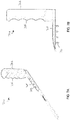
- FIGS. 1A and 1B depict an elevated side view and a cross-sectional view, respectively, of a plate 10 including at least one opening such as, for example, a hole 12 (eight holes shown in FIG. 1A ).
- the hole 12 extends through the plate 10 and is configured to accept a fastener (not shown) that is able to dynamically compress the bone and/or affix the plate 10 to the bone.
- the hole 12 may include threads 14 configured to correspond to threads of a fastener (not shown).
- FIG. 2 illustrate the plate 10 implanted along the dorsal side of a patient's hand.
- FIG. 3 depicts the retraction necessary to access the dorsal side of the patient's hand to implant the plate 10.
- the opening that permits access to the target site is extremely small. As such, it has been difficult to place and manipulate such a plate during the implantation process.
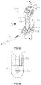
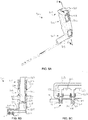
- FIGS. 4A-4D depict a plate inserter 400 in accordance with embodiments of the present disclosure.
- the plate insert 400 includes a body 402 extending from an upper end 404 to a lower end 406.
- the lower end 406 includes an opening 407 configured to receive a portion of the plate 10 to be held by the plate inserter 400.
- the body 402 further includes a gripping portion 408 configured to easily be gripped by a user's hand.
- a plate locking mechanism 410 is disposed within the body 402.
- the plate locking mechanism 410 includes an actuator 412, which extends through the upper end 404.
- the actuator 412 includes a rotatable lever 414 coupled to an actuator body 416.
- the actuator body 416 includes a protruding element 418 that extends radially outward from the actuator body 416 into a groove 420 formed on an interior wall 422 of the body 402.
- the groove 420 is sloped such that when a user turns the lever 414 (and thus the actuator body 416) in a first direction (indicated by arrow A in FIG. 4B ), movement of the protruding element 418 along the groove 420 forces the actuator body 416 to move downwards.
- Turning the lever 414 in a second direction (indicated by arrow B in FIG. 4C ) opposite the first direction forces the actuator body 416 to move upwards.
- the plate locking mechanism 410 further includes a plate engagement body 424 disposed beneath the actuator body 416.
- the plate engagement body 424 is coupled to the actuator body 416 in a way that allows the actuator body 416 to rotate relative to the plate engagement body.
- the plate engagement body 424 may include a spherical protrusion 426 extending upwardly from an upper surface 428 of the plate engagement body 424 into a corresponding spherical recess 430 formed in a bottom surface 432 of the actuator body 416.
- the plate engagement body 424 includes one or more engagement members 434 (two shown in FIG. 4D ) extending downwardly from a bottom surface 436 of the plate engagement body 424.
- the engagement members 434 are configured to engage (i.e., be inserted into) the holes 12 of the plate 10. After the plate 10 is inserted into the opening 407, the holes 12 are disposed beneath the one or more engagement members 434. Rotation of the lever 414 in the first direction causes the actuator body 416 and the plate engagement body 424 downwards so that the one or more engagement members 434 are inserted into corresponding holes 12. The user may subsequently insert the plate 10 into patient and manipulate the plate as desired. When the user wishes to disengage the plate inserter 400 from the plate 10, the user rotates the lever 414 in the second direction so that the engagement members 434 retract upwards and out of engagement with the holes 12.
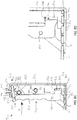
- FIGS. 5A-5I depict a plate inserter 500 in accordance with embodiments of the present disclosure.
- the plate inserter 500 includes a frame 502 and an actuator handle 504 rotatably coupled to the frame 502 via a pin connection 505.
- the frame 502 extends from an upper end 506 to a lower end 508.
- the lower end 508 includes a plate support base 510 having a groove 512 configured and dimensioned to receive the plate 10 therein.
- the actuator handle 504 also includes a gripping portion 509 configured to easily be gripped by a user's hand.
- the plate inserter 500 further includes an engagement body 514 disposed within the frame 502.
- a lower portion 516 of the actuator handle 504 extends into an opening 518 of the engagement body 514 to cause vertical movement of the engagement body 514, as will be described below.
- the engagement body 514 includes at least one engagement member 520 (two shown) extending downwardly from a bottom surface 522 of the engagement body 514.
- the engagement members 520 are configured to engage (i.e., be inserted into) the holes 12 of the plate 10. In use, the plate 10 is inserted into the groove 512 until it contacts a back wall 523 of the frame 502. Subsequently, the engagement members 520 are inserted into the holes 12 as described below.
- the plate inserter 500 includes a first torsion spring 524 mounted on a post 526 within the frame 502. A free end 528 of the torsion spring 524 is in contact with the actuator handle 504 to bias it towards the position shown in FIGS. 5H and 5I , in which the engagement members 520 do not engage the holes 12 of the plate 10.
- the user grips the gripping portion 509 and squeezes the actuator handle 504 in the direction indicated by arrow A (shown in FIGS. 5A and 5C ).
- the actuator handle 504 rotates in a clockwise direction about the pin connection 505, thus moving the lower portion 516 away from a back wall 530 of the opening 518.
- the lower portion 516 includes a tip 532 that is shaped so that movement of the lower portion 516 away from the back wall 530 results in the tip 532 exerting a downward force on the engagement body 514, thus moving the engagement members 520 into the holes 10.
- an upper portion 534 of the actuator handle 504 includes a retention member 536 pivotally coupled to the upper portion 534 via a pin connection 538.
- the retention member 536 includes an upwardly extending lip 540 configured to be disposed in a corresponding retention recess 542 formed on the interior of the frame 502 when the inserter 500 is in the plate engagement position (shown in FIGS. 5C-5E ).
- a second torsion spring 543 is coupled to the actuator handle 504 via a pin connection 545.
- a free end 547 of the torsion spring 543 contacts the retention member 536 and is configured to bias the retention member 536 upward.
- the inserter 500 is locked in the plate engagement position so that the plate 10 can be manipulated as desired.
- a button 544 disposed in the upper end 506 is pressed. Pressing the button 544 causes a lower portion of the button 544 to push down on the retention member 536 (as shown in FIG. 5F ) to overcome the biasing force of the second torsion spring 543, thus moving the lip 540 out of the retention recess 542 (as shown in FIG. 5G ). Under the biasing force of the first torsion spring 524, the actuator handle 504 returns to the disengaged position shown in FIG. 5H .
- the frame 502 includes a lip 546 that retains the upwardly extending lip 540 when the actuator handle returns to the disengaged position (as shown in FIG. 5G ).
- a biasing element 548 (e.g., a helical spring) may be disposed between the button 544 and the frame 502 to bias the button 544 upwards such that the button 544 returns to its original position after it is pressed down to release the retention member 536.
- FIGS. 6A and 6B depict a plate inserter 600 in accordance with embodiments of the present disclosure.
- the plate inserter 600 includes a body 602 having an upper portion 604, an intermediate portion 606, and a lower portion 608.
- the upper and lower portions of the body 604, 608 are separated into two independent halves.
- the intermediate portion 606 joins the two halves of the body 602.
- the lower portion 608 includes an opening 610 configured to receive the plate 10 therein.
- the size of the opening 610 is slightly smaller than the plate 10 such that insertion of the plate 10 into the opening 610 causes outward flexure of the lower portion 608 of the body 602. As a result, the plate 10 is held within the opening 10 by compression caused by the flexure of the body 602.
- the upper portion 604 and at least a portion of the lower portion 608 include a gripping surface 612 configured to be grasped by the hand of a user.
- the plate 10 is inserted into the opening 610 until it contacts an interior rear surface (not shown) of the body 602. As noted above, the plate 10 is held within the opening 610 by compression of the lower portion 608. A user may then manipulate the plate 10 disposed within the inserter 600 as desired. When it is time for the plate 10 to be removed from the inserter 600, the user squeezes the upper portion 604 inwards, causing the lower portion 608 to flex outward, thus loosening the plate and allowing for its removal.
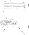
- FIGS. 7A and 7B depict a plate inserter 700 in accordance with embodiments of the present disclosure.
- the plate inserter 700 includes a body 702 coupled to an engagement portion 704. Together, the body 702 and the engagement portion 704 form an L-shape.
- the body 702 and the engagement portion 704 are integrally formed (i.e., monolithic).
- the body 702 includes a gripping surface 706 configured to be gripped by a user's hand.
- the engagement portion 704 includes at least one engagement hole 708 (four shown in FIGS. 7A and 7B ) that correspond to at least one of the holes 12 of the plate 10.
- the engagement holes 708 are configured to receive corresponding fasteners 710 (e.g., screws) such that the fasteners 710 extend through the engagement holes 708 and corresponding holes 12 to couple the plate 10 to the engagement portion 704.
- the inserter 700 advantageously provides users the ability to use some engagement holes 708 for coupling the plate 10 to the inserter 700 and the remaining engagement holes 708 for securing the plate 10 directly to bone while the plate 10 is still attached to the inserter 700. After the plate 10 has been moved/manipulated as desired, the user removes the fasteners 710 to decouple the plate 10 from the inserter 700.
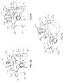
- FIGS. 8A-8E depict a plate inserter 800 in accordance with embodiments of the present disclosure.
- the plate inserter 800 includes some elements similar to the inserter 400 described above.
- the inserter 800 includes a body 802 extending from an upper end 804 to a lower end 806, a gripping portion 808, a plate locking mechanism 810 having an actuator 812 that extends through the upper end 804.
- the actuator 812 includes a rotatable lever 814 coupled to an actuator body 816.
- the actuator body 816 includes a protruding element 818 that extends radially outward from the actuator body 816 into a groove 820 formed on an interior wall 822 of the body 802.
- the groove 820 is sloped such that when a user turns the lever 814 (and thus the actuator body 816) in a first direction, movement of the protruding element 818 along the groove 820 forces the actuator body 816 to move downwards. Turning the lever 814 in a second direction opposite the first direction forces the actuator body 816 to move upwards.
- the inserter 800 differs from the inserter 400 in that the body 802 includes a horizontal portion 813 extending from the lower end 806 of the body.
- the horizontal portion 813 includes one or more collets 815 (two shown in FIGS. 8B-8E ) configured to be inserted into the holes 12 of the plate 10.
- Each collet 815 includes a conical portion 817 extending downwards from the horizontal portion 813 and terminating at a collar 819.
- Each collet 815 also includes two or more slots 821(one shown in FIGS. 8B-8E due to cross-sectional view) separating the collet 815 into two or more prongs 823.
- the collets 815 have a maximum diameter that is less than the diameter of the holes 12 so that the collets 815 can be inserted into the holes 12 with relative ease.
- the plate locking mechanism 810 further includes a plate engagement body 824 disposed beneath the actuator body 816.
- the plate engagement body 824 includes a main body 825 and a horizontal arm 827 extending from the main body 825 into the horizontal portion 813 of the body 802. Similar to the plate engagement body 424, the plate engagement body 824 is coupled to the actuator body 816 in a way that allows the actuator body 816 to rotate relative to the plate engagement body.
- the plate engagement body 824 may include a spherical protrusion 826 extending upwardly from an upper surface 828 of the plate engagement body 824 into a corresponding spherical recess 830 formed in a bottom surface 832 of the actuator body 816.
- Such a coupling enables the two bodies 816, 824 to be coupled, while allowing for the rotation of the actuator body 816 relative to the plate engagement body 824.
- the plate engagement body 824 includes one or more posts 834 (two shown in FIGS. 8B-8E ) corresponding to the one of more collets 815.
- the one or more posts 834 extend downwardly from a bottom surface 836 of the horizontal arm 827 and are configured to engage (i.e., be inserted into) the collets 815.
- the one or more posts 834 are inserted through central openings 829 of the collets 815 to deflect the prongs 823 radially outward.
- the collars 819 of the collets 815 provide a retention force so that the plate 10 does not slide off after the expansion of the collets 815.
- the inserter 800 is provisionally coupled to the plate 10 by insertion of the collets 815 through the holes 12. Subsequently, the lever 814 is rotated in the first direction to force the actuator body 816 and the plate engagement body 824 downwards so that the posts 834 move into the collets 815, thus forcing the prongs radially outward and locking the plate 10 to the inserter 800. The user may subsequently insert the plate 10 into patient and manipulate the plate 10 as desired. When the user wishes to disengage the plate inserter 800 from the plate 10, the user rotates the lever 814 in the second direction so that the posts 834 retract upwards and out of the collets 815. In some embodiments, one or more springs 833 may be disposed about corresponding ones of the one or more posts 834 to bias the engagement body 824 towards the unlocked position, thus ensuring the posts 834 do not unintentionally drop into the collets 815.
Landscapes
- Health & Medical Sciences (AREA)
- Orthopedic Medicine & Surgery (AREA)
- Surgery (AREA)
- Life Sciences & Earth Sciences (AREA)
- Heart & Thoracic Surgery (AREA)
- Veterinary Medicine (AREA)
- Engineering & Computer Science (AREA)
- Biomedical Technology (AREA)
- Nuclear Medicine, Radiotherapy & Molecular Imaging (AREA)
- Medical Informatics (AREA)
- Molecular Biology (AREA)
- Animal Behavior & Ethology (AREA)
- General Health & Medical Sciences (AREA)
- Public Health (AREA)
- Neurology (AREA)
- Dentistry (AREA)
- Oral & Maxillofacial Surgery (AREA)
- Prostheses (AREA)
- Surgical Instruments (AREA)
Abstract
Description
- The present disclosure relates to surgical devices, and more particularly, stabilization systems, for example, for trauma applications.
- Bone fractures are often repaired by internal fixation of the bone, such as diaphyseal bone, using one or more plates. The plate is held against the fractured bone with screws, for example, which engage the bone and heads, which provide a compressive force against the plate. The plate and bone are thus forced against each other in a manner that transfers load primarily between a bone-contacting surface of the plate and the bone surface to reinforce the fractured bone during healing. This manner of plating generally creates relatively low stress concentration in the bone, as there may be a large contact area between the plate and the diaphyseal bone surface permitting transfer of load to be dispersed. Of course, the designs of the plates may vary based on the location and type of fracture.
- Without a handle attachment or similar apparatus, it can be difficult to maintain a firm grip on a plate during insertion of the plate through an incision, accurately place the plate, or apply any force(s) required for manipulation of the plate in different areas of the patient's body.
- To meet this and other needs, devices, systems, and methods for inserting a plate are provided herein. In some embodiments, an apparatus for inserting a bone plate to a target site, the apparatus includes a body extending from an upper end to a lower end; a plate receiving portion configured to receive the bone plate; and a plate engaging mechanism configured to couple the bone plate to the body, wherein the body includes a gripping surface configured to be gripped by a user's hand.
- A more complete understanding of the present invention, and the attendant advantages and features thereof, will be more readily understood by reference to the following detailed description when considered in conjunction with the accompanying drawings wherein:
-
FIG. 1A depicts a trauma plate suitable for use with a plate inserter in accordance with embodiments of the present disclosure. -
FIG. 1B is a cross-sectional view of the plate ofFIG. 1A taken along line B-B'. -
FIG. 2 depicts the trauma plate ofFIGS. 1A and 1B implanted in a patient. -
FIG. 3 depicts the retraction of patient anatomy to implant the trauma plate ofFIGS. 1A and 1B . -
FIGS 4A-4D depict an apparatus for inserting a plate in accordance with embodiments of the present disclosure. -
FIGS. 5A-5I depict an apparatus for inserting a plate in accordance with embodiments of the present disclosure. -
FIGS. 6A and 6B depict an apparatus for inserting a plate in accordance with embodiments of the present disclosure. -
FIGS. 7A and 7B depict an apparatus for inserting a plate in accordance with embodiments of the present disclosure. -
FIGS. 8A-8E depict an apparatus for inserting a plate in accordance with embodiments of the present disclosure. - Embodiments of the disclosure are generally directed to devices, systems, and methods for inserting a plate through an incision and to a target area within a patient. Specifically, embodiments are directed to a plate inserter configured to advantageously allow for the plate to be coupled to the inserter on a back table or intra-operatively to an end of a plate opposite an end already fixed to bone. The inventive inserter also advantageously provides a low profile on the lowermost surface of the inserter (i.e., the portion that couples to the plate) to avoid soft tissue irritation, ease of operation with one hand, and a comfortable grip that fits the contours of a user's hand.
- Although the following description and the figures show a specific plate, it should be noted that the inventive plate inserter may be used with any type of plate. Exemplary plates may include plates adapted to contact one or more of a femur, a distal tibia, a proximal tibia, a proximal humerus, a distal humerus, a clavicle, a fibula, an ulna, a radius, bones of the foot, bones of the hand, or other suitable bone or bones. The bone plate may be curved, contoured, straight, or flat. The plate may have a head portion that is contoured to match a particular bone surface, such as a metaphysis or diaphysis, flares out from the shaft portion, forms an L-shape, T-shape, Y-shape, etc., with the shaft portion, or that forms any other appropriate shape to fit the anatomy of the bone to be treated.
- The embodiments of the disclosure and the various features and advantageous details thereof are explained more fully with reference to the non-limiting embodiments and examples that are described and/or illustrated in the accompanying drawings and detailed in the following description. The features of one embodiment may be employed with other embodiments as the skilled artisan would recognize, even if not explicitly stated herein. Descriptions of well-known components and processing techniques may be omitted so as to not unnecessarily obscure the embodiments of the disclosure. The examples used herein are intended merely to facilitate an understanding of ways in which the disclosure may be practiced and to further enable those of skill in the art to practice the embodiments of the disclosure. Accordingly, the examples and embodiments herein should not be construed as limiting the scope of the disclosure, which is defined solely by the appended claims and applicable law. Moreover, it is noted that like reference numerals represent similar features and structures throughout the several views of the drawings.
- Referring now to the drawings,
FIGS. 1A and 1B depict an elevated side view and a cross-sectional view, respectively, of aplate 10 including at least one opening such as, for example, a hole 12 (eight holes shown inFIG. 1A ). Thehole 12 extends through theplate 10 and is configured to accept a fastener (not shown) that is able to dynamically compress the bone and/or affix theplate 10 to the bone. As shown more clearly inFIG. 1B , thehole 12 may includethreads 14 configured to correspond to threads of a fastener (not shown). -
FIG. 2 illustrate theplate 10 implanted along the dorsal side of a patient's hand.FIG. 3 depicts the retraction necessary to access the dorsal side of the patient's hand to implant theplate 10. The opening that permits access to the target site is extremely small. As such, it has been difficult to place and manipulate such a plate during the implantation process. -
FIGS. 4A-4D depict aplate inserter 400 in accordance with embodiments of the present disclosure. In some embodiments, theplate insert 400 includes abody 402 extending from anupper end 404 to alower end 406. Thelower end 406 includes anopening 407 configured to receive a portion of theplate 10 to be held by theplate inserter 400. Thebody 402 further includes a grippingportion 408 configured to easily be gripped by a user's hand. Aplate locking mechanism 410 is disposed within thebody 402. In some embodiments, theplate locking mechanism 410 includes anactuator 412, which extends through theupper end 404. Theactuator 412 includes arotatable lever 414 coupled to anactuator body 416. Theactuator body 416 includes aprotruding element 418 that extends radially outward from theactuator body 416 into agroove 420 formed on aninterior wall 422 of thebody 402. Thegroove 420 is sloped such that when a user turns the lever 414 (and thus the actuator body 416) in a first direction (indicated by arrow A inFIG. 4B ), movement of the protrudingelement 418 along thegroove 420 forces theactuator body 416 to move downwards. Turning thelever 414 in a second direction (indicated by arrow B inFIG. 4C ) opposite the first direction forces theactuator body 416 to move upwards. - In some embodiments, the
plate locking mechanism 410 further includes aplate engagement body 424 disposed beneath theactuator body 416. Theplate engagement body 424 is coupled to theactuator body 416 in a way that allows theactuator body 416 to rotate relative to the plate engagement body. For example, as shown inFIG. 4D , theplate engagement body 424 may include a spherical protrusion 426 extending upwardly from anupper surface 428 of theplate engagement body 424 into a correspondingspherical recess 430 formed in abottom surface 432 of theactuator body 416. Such a coupling enables the twobodies actuator body 416 relative to theplate engagement body 424. - The
plate engagement body 424 includes one or more engagement members 434 (two shown inFIG. 4D ) extending downwardly from a bottom surface 436 of theplate engagement body 424. Theengagement members 434 are configured to engage (i.e., be inserted into) theholes 12 of theplate 10. After theplate 10 is inserted into theopening 407, theholes 12 are disposed beneath the one ormore engagement members 434. Rotation of thelever 414 in the first direction causes theactuator body 416 and theplate engagement body 424 downwards so that the one ormore engagement members 434 are inserted into correspondingholes 12. The user may subsequently insert theplate 10 into patient and manipulate the plate as desired. When the user wishes to disengage theplate inserter 400 from theplate 10, the user rotates thelever 414 in the second direction so that theengagement members 434 retract upwards and out of engagement with theholes 12. -
FIGS. 5A-5I depict aplate inserter 500 in accordance with embodiments of the present disclosure. In some embodiments, theplate inserter 500 includes aframe 502 and anactuator handle 504 rotatably coupled to theframe 502 via apin connection 505. Theframe 502 extends from anupper end 506 to alower end 508. As shown more clearly inFIGS. 5A ,5C, and 5D , thelower end 508 includes aplate support base 510 having agroove 512 configured and dimensioned to receive theplate 10 therein. The actuator handle 504 also includes agripping portion 509 configured to easily be gripped by a user's hand. - As shown more clearly in
FIGS. 5C-5D and5H-5I , theplate inserter 500 further includes anengagement body 514 disposed within theframe 502. Alower portion 516 of theactuator handle 504 extends into anopening 518 of theengagement body 514 to cause vertical movement of theengagement body 514, as will be described below. Theengagement body 514 includes at least one engagement member 520 (two shown) extending downwardly from abottom surface 522 of theengagement body 514. Theengagement members 520 are configured to engage (i.e., be inserted into) theholes 12 of theplate 10. In use, theplate 10 is inserted into thegroove 512 until it contacts aback wall 523 of theframe 502. Subsequently, theengagement members 520 are inserted into theholes 12 as described below. - In some embodiments, the
plate inserter 500 includes afirst torsion spring 524 mounted on apost 526 within theframe 502. Afree end 528 of thetorsion spring 524 is in contact with theactuator handle 504 to bias it towards the position shown inFIGS. 5H and 5I , in which theengagement members 520 do not engage theholes 12 of theplate 10. To move theengagement members 520 into theholes 12, thus fixing theplate 10 to theinserter 500, the user grips thegripping portion 509 and squeezes theactuator handle 504 in the direction indicated by arrow A (shown inFIGS. 5A and5C ). When this movement occurs, theactuator handle 504 rotates in a clockwise direction about thepin connection 505, thus moving thelower portion 516 away from aback wall 530 of theopening 518. Thelower portion 516 includes atip 532 that is shaped so that movement of thelower portion 516 away from theback wall 530 results in thetip 532 exerting a downward force on theengagement body 514, thus moving theengagement members 520 into theholes 10. - Referring to
FIGS. 5E-5G , to retain theinserter 500 in the plate engagement position just described, anupper portion 534 of theactuator handle 504 includes aretention member 536 pivotally coupled to theupper portion 534 via apin connection 538. Theretention member 536 includes an upwardly extendinglip 540 configured to be disposed in acorresponding retention recess 542 formed on the interior of theframe 502 when theinserter 500 is in the plate engagement position (shown inFIGS. 5C-5E ). Asecond torsion spring 543 is coupled to theactuator handle 504 via apin connection 545. Afree end 547 of thetorsion spring 543 contacts theretention member 536 and is configured to bias theretention member 536 upward. When thelip 540 of theretention member 542 is disposed within theretention recess 542 under the bias of the second torsion spring 536 (as shown inFIG. 5E ), theinserter 500 is locked in the plate engagement position so that theplate 10 can be manipulated as desired. - To disengage the
engagement members 520 from theholes 12, abutton 544 disposed in theupper end 506 is pressed. Pressing thebutton 544 causes a lower portion of thebutton 544 to push down on the retention member 536 (as shown inFIG. 5F ) to overcome the biasing force of thesecond torsion spring 543, thus moving thelip 540 out of the retention recess 542 (as shown inFIG. 5G ). Under the biasing force of thefirst torsion spring 524, the actuator handle 504 returns to the disengaged position shown inFIG. 5H . In some embodiments, theframe 502 includes alip 546 that retains the upwardly extendinglip 540 when the actuator handle returns to the disengaged position (as shown inFIG. 5G ). In some embodiments, a biasing element 548 (e.g., a helical spring) may be disposed between thebutton 544 and theframe 502 to bias thebutton 544 upwards such that thebutton 544 returns to its original position after it is pressed down to release theretention member 536. -
FIGS. 6A and 6B depict aplate inserter 600 in accordance with embodiments of the present disclosure. In some embodiments, theplate inserter 600 includes abody 602 having anupper portion 604, anintermediate portion 606, and alower portion 608. The upper and lower portions of thebody intermediate portion 606 joins the two halves of thebody 602. Thelower portion 608 includes anopening 610 configured to receive theplate 10 therein. In some embodiments, the size of theopening 610 is slightly smaller than theplate 10 such that insertion of theplate 10 into theopening 610 causes outward flexure of thelower portion 608 of thebody 602. As a result, theplate 10 is held within theopening 10 by compression caused by the flexure of thebody 602. As shown inFIGS. 6A and 6B , theupper portion 604 and at least a portion of thelower portion 608 include agripping surface 612 configured to be grasped by the hand of a user. In use, theplate 10 is inserted into theopening 610 until it contacts an interior rear surface (not shown) of thebody 602. As noted above, theplate 10 is held within theopening 610 by compression of thelower portion 608. A user may then manipulate theplate 10 disposed within theinserter 600 as desired. When it is time for theplate 10 to be removed from theinserter 600, the user squeezes theupper portion 604 inwards, causing thelower portion 608 to flex outward, thus loosening the plate and allowing for its removal. -
FIGS. 7A and 7B depict aplate inserter 700 in accordance with embodiments of the present disclosure. In some embodiments, theplate inserter 700 includes abody 702 coupled to anengagement portion 704. Together, thebody 702 and theengagement portion 704 form an L-shape. In some embodiments, thebody 702 and theengagement portion 704 are integrally formed (i.e., monolithic). Thebody 702 includes a gripping surface 706 configured to be gripped by a user's hand. In some embodiments, theengagement portion 704 includes at least one engagement hole 708 (four shown inFIGS. 7A and 7B ) that correspond to at least one of theholes 12 of theplate 10. The engagement holes 708 are configured to receive corresponding fasteners 710 (e.g., screws) such that thefasteners 710 extend through the engagement holes 708 andcorresponding holes 12 to couple theplate 10 to theengagement portion 704. Theinserter 700 advantageously provides users the ability to use someengagement holes 708 for coupling theplate 10 to theinserter 700 and the remaining engagement holes 708 for securing theplate 10 directly to bone while theplate 10 is still attached to theinserter 700. After theplate 10 has been moved/manipulated as desired, the user removes thefasteners 710 to decouple theplate 10 from theinserter 700. -
FIGS. 8A-8E depict aplate inserter 800 in accordance with embodiments of the present disclosure. Theplate inserter 800 includes some elements similar to theinserter 400 described above. For example, theinserter 800 includes abody 802 extending from anupper end 804 to alower end 806, a grippingportion 808, aplate locking mechanism 810 having an actuator 812 that extends through theupper end 804. Also similar to theinserter 400, theactuator 812 includes arotatable lever 814 coupled to anactuator body 816. Theactuator body 816 includes aprotruding element 818 that extends radially outward from theactuator body 816 into agroove 820 formed on an interior wall 822 of thebody 802. Thegroove 820 is sloped such that when a user turns the lever 814 (and thus the actuator body 816) in a first direction, movement of the protrudingelement 818 along thegroove 820 forces theactuator body 816 to move downwards. Turning thelever 814 in a second direction opposite the first direction forces theactuator body 816 to move upwards. - However, the
inserter 800 differs from theinserter 400 in that thebody 802 includes ahorizontal portion 813 extending from thelower end 806 of the body. In some embodiment, thehorizontal portion 813 includes one or more collets 815 (two shown inFIGS. 8B-8E ) configured to be inserted into theholes 12 of theplate 10. Eachcollet 815 includes aconical portion 817 extending downwards from thehorizontal portion 813 and terminating at acollar 819. Eachcollet 815 also includes two or more slots 821(one shown inFIGS. 8B-8E due to cross-sectional view) separating thecollet 815 into two ormore prongs 823. Thecollets 815 have a maximum diameter that is less than the diameter of theholes 12 so that thecollets 815 can be inserted into theholes 12 with relative ease. - The
plate locking mechanism 810 further includes aplate engagement body 824 disposed beneath theactuator body 816. Theplate engagement body 824 includes amain body 825 and ahorizontal arm 827 extending from themain body 825 into thehorizontal portion 813 of thebody 802. Similar to theplate engagement body 424, theplate engagement body 824 is coupled to theactuator body 816 in a way that allows theactuator body 816 to rotate relative to the plate engagement body. For example, as shown inFIGS. 8B and8D , theplate engagement body 824 may include aspherical protrusion 826 extending upwardly from anupper surface 828 of theplate engagement body 824 into a correspondingspherical recess 830 formed in abottom surface 832 of theactuator body 816. Such a coupling enables the twobodies actuator body 816 relative to theplate engagement body 824. - The
plate engagement body 824 includes one or more posts 834 (two shown inFIGS. 8B-8E ) corresponding to the one ofmore collets 815. The one ormore posts 834 extend downwardly from abottom surface 836 of thehorizontal arm 827 and are configured to engage (i.e., be inserted into) thecollets 815. Aftercollets 815 are inserted into theholes 12, the one ormore posts 834 are inserted through central openings 829 of thecollets 815 to deflect theprongs 823 radially outward. As a result, theplate 10 is locked onto theinserter 800. Thecollars 819 of thecollets 815 provide a retention force so that theplate 10 does not slide off after the expansion of thecollets 815. - In use, the
inserter 800 is provisionally coupled to theplate 10 by insertion of thecollets 815 through theholes 12. Subsequently, thelever 814 is rotated in the first direction to force theactuator body 816 and theplate engagement body 824 downwards so that theposts 834 move into thecollets 815, thus forcing the prongs radially outward and locking theplate 10 to theinserter 800. The user may subsequently insert theplate 10 into patient and manipulate theplate 10 as desired. When the user wishes to disengage theplate inserter 800 from theplate 10, the user rotates thelever 814 in the second direction so that theposts 834 retract upwards and out of thecollets 815. In some embodiments, one ormore springs 833 may be disposed about corresponding ones of the one ormore posts 834 to bias theengagement body 824 towards the unlocked position, thus ensuring theposts 834 do not unintentionally drop into thecollets 815. - Although the invention has been described in detail and with reference to specific embodiments, it will be apparent to one skilled in the art that various changes and modifications can be made without departing from the spirit and scope of the invention. Thus, it is intended that the invention covers the modifications and variations of this invention provided they come within the scope of the appended claims and their equivalents. It is expressly intended, for example, that all ranges broadly recited in this document include within their scope all narrower ranges which fall within the broader ranges. It is also intended that the components of the various devices disclosed above may be combined or modified in any suitable configuration.
- The invention could be inter alia defined by the following examples:
- 1. An apparatus for inserting a bone plate to a target site, the apparatus comprising: a body extending from an upper end to a lower end;a plate receiving portion configured to receive the bone plate; and a plate engaging mechanism configured to couple the bone plate to the body, wherein the body includes a gripping surface configured to be gripped by a user's hand.
- 2. The apparatus of example 1, wherein the plate receiving portion is an opening formed proximate the lower end of the body.
- 3. The apparatus of example 2, wherein plate engaging mechanism comprises: an actuator; and a plate engagement body configured to lock the bone plate to the apparatus, the plate engagement body having one or more plate engagement members extending downwardly from the plate engagement body and configured to be inserted into holes of the bone plate.
- 4. The apparatus of example 3, wherein the actuator extends though the upper end of the body and includes a rotatable lever coupled to an actuator body disposed the body of the apparatus, wherein the actuator body includes a protruding element extending radially outwards from the actuator body, wherein a groove is formed in an inner wall of the body of the apparatus to receive the protruding element therein, and wherein the groove includes a slope such that rotation of the lever in a first direction forces the actuator body downwards from an initial position and rotation of the lever in a second direction forces the actuator upwards from an engaged position.
- 5. The apparatus of example 4, wherein the plate engagement body includes a spherical protrusion extending upwardly from an upper surface of the plate engagement body, wherein the actuator body includes a corresponding spherical recess formed in a bottom surface of the actuator body and configured to receive the spherical protrusion of the plate engagement body such that rotation of the actuator body relative to the plate engagement body is allowed and such that downward or upward motion of the actuator body results in corresponding downward or upward motion of the plate engagement body.
- 6. The apparatus of example 2, wherein the body of the apparatus includes an upper portion an intermediate portion, and a lower portion, wherein the upper and lower portions are separated into two independent halves, wherein the intermediate portion joins the two independent halves of the upper and lower portions, wherein a size of the opening is smaller than a size of the bone plate such that when the bone plate is inserted into the opening, the bone plate causes outward flexure of the lower portion, and wherein squeezing of the upper portion causes outward flexure of the lower portion.
- 7. The apparatus of example 1, wherein the body includes a frame, and wherein the plate receiving portion is a groove formed in a lower portion of the frame.
- 8. The apparatus of example 7, wherein plate engaging mechanism comprises: an actuator handle disposed within the frame and having a retention member pivotably coupled thereto, the retention member including a lip; and a plate engagement body configured to lock the bone plate to the apparatus, the plate engagement body having one or more plate engagement members extending downwardly from the plate engagement body and configured to be inserted into holes of the bone plate, wherein squeezing the actuator handle causes downward motion of the plate engagement body to a locked state in which the one or more plate engagement members extend into holes of the bone plate and in which the lip of the retention member is retained in a groove formed in the frame such that the actuator handle and the engagement body remain in the locked state.
- 9. The apparatus of example 8, further comprising: a release button disposed in a top portion of the frame, wherein the release button is configured move the lip of the retention member out of the groove when the release button is pressed such that the actuator handle and the plate engagement body return to an initial position in which the one or more plate engagement members do not extend into the holes of the bone plate.
- 10. The apparatus of example 1, wherein the plate receiving portion extends horizontally outward from a bottom portion of the body and is configured to abut the bone plate.
- 11. The apparatus of example 10, wherein the plate receiving portion includes one or more through holes configured to align with the holes of the bone plate when the bone plate buts the plate receiving portion, and wherein the one or more through holes are configured to receive a fastener to extend through the one or more through holes and into the holes of the bone plate to couple the bone plate to the plate receiving portion.
- 12. The apparatus of example 10, wherein the plate receiving portion includes one or more collets extending downwardly from the plate receiving portion and configured to engage holes of the bone plate.
- 13. The apparatus of example 12, wherein plate engaging mechanism comprises: an actuator; and a plate engagement body configured to lock the bone plate to the apparatus, the plate engagement body having a main body and an arm extending from the main body into the plate receiving portion, and wherein the plate engagement body includes one or more posts extending downwardly from the plate engagement body and configured to be inserted through corresponding ones of the one or more collets, wherein insertion of the one or more posts through the one or more collets causes prongs of the collets to move radially outwards to lock the bone plate to the plate receiving portion.
- 14. The apparatus of example 13, wherein the actuator extends though the upper end of the body and includes a rotatable lever coupled to an actuator body disposed the body of the apparatus, wherein the actuator body includes a protruding element extending radially outwards from the actuator body, wherein a groove is formed in an inner wall of the body of the apparatus to receive the protruding element therein, and wherein the groove includes a slope such that rotation of the lever in a first direction forces the actuator body downwards from an initial position and rotation of the lever in a second direction forces the actuator upwards from an engaged position.
- 15. The apparatus of example 14, wherein the plate engagement body includes a spherical protrusion extending upwardly from an upper surface of the plate engagement body, wherein the actuator body includes a corresponding spherical recess formed in a bottom surface of the actuator body and configured to receive the spherical protrusion of the plate engagement body such that rotation of the actuator body relative to the plate engagement body is allowed and such that downward or upward motion of the actuator body results in corresponding downward or upward motion of the plate engagement body.
Claims (15)
- An apparatus for inserting a bone plate to a target site, the apparatus comprising:- a body extending from an upper end to a lower end;- a plate receiving portion configured to receive the bone plate; and- a plate engaging mechanism configured to couple the bone plate to the body,- wherein the body includes a gripping surface configured to be gripped by a user's hand.
- The apparatus of claim 1, wherein the plate receiving portion is an opening formed proximate the lower end of the body.
- The apparatus of claim 2, wherein plate engaging mechanism comprises:- an actuator; and- a plate engagement body configured to lock the bone plate to the apparatus, the plate engagement body having preferably one or more plate engagement members extending downwardly from the plate engagement body and configured to be inserted into holes of the bone plate.
- The apparatus of claim 3, wherein the actuator extends though the upper end of the body and includes a rotatable lever coupled to an actuator body disposed the body of the apparatus, wherein the actuator body includes preferably a protruding element extending radially outwards from the actuator body, wherein a groove is preferably formed in an inner wall of the body of the apparatus to receive the protruding element therein, and wherein the groove preferably includes a slope such that rotation of the lever in a first direction forces the actuator body downwards from an initial position and rotation of the lever in a second direction forces the actuator upwards from an engaged position.
- The apparatus of claim 4, wherein the plate engagement body includes a spherical protrusion extending upwardly from an upper surface of the plate engagement body, wherein the actuator body preferably includes a corresponding spherical recess formed in a bottom surface of the actuator body and configured to receive the spherical protrusion of the plate engagement body such that rotation of the actuator body relative to the plate engagement body is allowed and such that downward or upward motion of the actuator body results in corresponding downward or upward motion of the plate engagement body.
- The apparatus of claim 2, wherein the body of the apparatus includes an upper portion an intermediate portion, and a lower portion, wherein the upper and lower portions are preferably separated into two independent halves, wherein the intermediate portion preferably joins the two independent halves of the upper and lower portions, wherein a size of the opening is preferably smaller than a size of the bone plate such that when the bone plate is inserted into the opening, the bone plate causes outward flexure of the lower portion, and wherein squeezing of the upper portion causes outward flexure of the lower portion.
- The apparatus of claim 1, wherein the body includes a frame, and wherein the plate receiving portion is a groove formed in a lower portion of the frame.
- The apparatus of claim 7, wherein plate engaging mechanism comprises:- an actuator handle disposed within the frame and having a retention member pivotably coupled thereto, the retention member including a lip; and- a plate engagement body configured to lock the bone plate to the apparatus, the plate engagement body having preferably one or more plate engagement members extending downwardly from the plate engagement body and configured to be inserted into holes of the bone plate,- wherein squeezing the actuator handle causes downward motion of the plate engagement body to a locked state in which the one or more plate engagement members extend into holes of the bone plate and in which the lip of the retention member is retained in a groove formed in the frame such that the actuator handle and the engagement body remain in the locked state.
- The apparatus of claim 8, further comprising: a release button disposed in a top portion of the frame, wherein the release button is preferably configured move the lip of the retention member out of the groove when the release button is pressed such that the actuator handle and the plate engagement body return to an initial position in which the one or more plate engagement members do not extend into the holes of the bone plate.
- The apparatus of claim 1, wherein the plate receiving portion extends horizontally outward from a bottom portion of the body and is configured to abut the bone plate.
- The apparatus of claim 10, wherein the plate receiving portion includes one or more through holes configured to align with the holes of the bone plate when the bone plate buts the plate receiving portion, and wherein preferably the one or more through holes are configured to receive a fastener to extend through the one or more through holes and into the holes of the bone plate to couple the bone plate to the plate receiving portion.
- The apparatus of claim 10, wherein the plate receiving portion includes one or more collets extending downwardly from the plate receiving portion and configured to engage holes of the bone plate.
- The apparatus of claim 12, wherein plate engaging mechanism comprises:- an actuator; and- a plate engagement body configured to lock the bone plate to the apparatus, the plate engagement body having a main body and an arm extending from the main body into the plate receiving portion, and wherein the plate engagement body preferably includes one or more posts extending downwardly from the plate engagement body and configured to be inserted through corresponding ones of the one or more collets, wherein insertion of the one or more posts through the one or more collets preferably causes prongs of the collets to move radially outwards to lock the bone plate to the plate receiving portion.
- The apparatus of claim 13, wherein the actuator extends though the upper end of the body and includes a rotatable lever coupled to an actuator body disposed the body of the apparatus, wherein the actuator body includes a protruding element extending radially outwards from the actuator body, wherein a groove is preferably formed in an inner wall of the body of the apparatus to receive the protruding element therein, and wherein the groove preferably includes a slope such that rotation of the lever in a first direction forces the actuator body downwards from an initial position and rotation of the lever in a second direction forces the actuator upwards from an engaged position.
- The apparatus of claim 14, wherein the plate engagement body includes a spherical protrusion extending upwardly from an upper surface of the plate engagement body, wherein the actuator body preferably includes a corresponding spherical recess formed in a bottom surface of the actuator body and configured to receive the spherical protrusion of the plate engagement body such that rotation of the actuator body relative to the plate engagement body is allowed and such that downward or upward motion of the actuator body results in corresponding downward or upward motion of the plate engagement body.
Applications Claiming Priority (1)
| Application Number | Priority Date | Filing Date | Title |
|---|---|---|---|
| US16/668,824 US11129627B2 (en) | 2019-10-30 | 2019-10-30 | Method and apparatus for inserting a bone plate |
Publications (2)
| Publication Number | Publication Date |
|---|---|
| EP3815638A1 true EP3815638A1 (en) | 2021-05-05 |
| EP3815638B1 EP3815638B1 (en) | 2024-07-31 |
Family
ID=73029964
Family Applications (1)
| Application Number | Title | Priority Date | Filing Date |
|---|---|---|---|
| EP20204195.0A Active EP3815638B1 (en) | 2019-10-30 | 2020-10-27 | Apparatus for inserting a bone plate |
Country Status (3)
| Country | Link |
|---|---|
| US (4) | US11129627B2 (en) |
| EP (1) | EP3815638B1 (en) |
| JP (1) | JP7036884B2 (en) |
Citations (5)
| Publication number | Priority date | Publication date | Assignee | Title |
|---|---|---|---|---|
| US20020147450A1 (en) * | 2001-04-06 | 2002-10-10 | Lehuec Jean-Charles | Anterior plating system and method |
| EP1661525A2 (en) * | 2004-11-30 | 2006-05-31 | Stryker Trauma SA | Bone plating implants and instruments including plate selection aid |
| US20150080975A1 (en) * | 2013-09-16 | 2015-03-19 | Aesculap Ag | Medical instrument |
| US20170000534A1 (en) * | 2015-07-01 | 2017-01-05 | Trimed, Incorporated | Method of securing a plate to a bone at a fracture site utilizing a detachable inserter |
| EP3552562A1 (en) * | 2018-04-11 | 2019-10-16 | Globus Medical, Inc. | Method and apparatus for locking a drill guide in a polyaxial hole |
Family Cites Families (284)
| Publication number | Priority date | Publication date | Assignee | Title |
|---|---|---|---|---|
| US1105105A (en) | 1912-02-10 | 1914-07-28 | William O'n Sherman | Surgical appliance. |
| US2486303A (en) | 1948-04-29 | 1949-10-25 | Harry Herschel Leiter | Surgical appliance for bone fractures |
| US3463148A (en) | 1966-01-20 | 1969-08-26 | Richards Mfg Co | Bone plate |
| US3695259A (en) | 1970-11-10 | 1972-10-03 | Clyde E Yost | Bone plate |
| US3716050A (en) | 1971-02-11 | 1973-02-13 | F Johnston | Olecranon plate |
| CH613858A5 (en) | 1977-04-22 | 1979-10-31 | Straumann Inst Ag | |
| US4187840A (en) | 1978-08-14 | 1980-02-12 | Watanabe Robert S | Bone plate clamp |
| CH651192A5 (en) | 1980-11-20 | 1985-09-13 | Synthes Ag | OSTEOSYNTHETIC DEVICE AND CORRESPONDING DRILL GAUGE. |
| FR2517536B1 (en) | 1981-12-09 | 1986-12-12 | Zbikowski Juan | FUNCTIONAL FIXING DEVICE FOR OSTEO-SYNTHESIS USING COMPRESSION PLATES |
| GB2158716B (en) | 1984-05-18 | 1987-09-30 | Technomed Gmk | Bone joining plate |
| US4683878A (en) | 1985-04-29 | 1987-08-04 | Kirschner Medical Corporation | Osteosynthetic fixation plate |
| PL147580B1 (en) | 1986-04-14 | 1989-06-30 | Plate for uniting epiphysis and diaphysis of broken bone | |
| US4776330A (en) | 1986-06-23 | 1988-10-11 | Pfizer Hospital Products Group, Inc. | Modular femoral fixation system |
| US4781183A (en) | 1986-08-27 | 1988-11-01 | American Cyanamid Company | Surgical prosthesis |
| US4966599A (en) | 1987-04-07 | 1990-10-30 | Pollock Richard A | Anatomical precontoured plating, instruments and methods |
| DE8706912U1 (en) | 1987-05-14 | 1987-08-27 | Howmedica GmbH, 2314 Schönkirchen | Small bone plate and screws, particularly for the treatment of fractures of the skull and facial skeleton or similar. |
| US5151103A (en) | 1987-11-03 | 1992-09-29 | Synthes (U.S.A.) | Point contact bone compression plate |
| CH673762A5 (en) | 1987-12-02 | 1990-04-12 | Synthes Ag | |
| US4923471A (en) | 1989-10-17 | 1990-05-08 | Timesh, Inc. | Bone fracture reduction and fixation devices with identity tags |
| IT1237496B (en) | 1989-10-26 | 1993-06-08 | Giuseppe Vrespa | SCREW DEVICE FOR ANCHORING BONE PROSTHESES, METHOD FOR THE APPLICATION OF SUCH DEVICE AND RELATED EQUIPMENT |
| DE9114118U1 (en) | 1991-11-13 | 1992-01-02 | Howmedica GmbH, 2314 Schönkirchen | Supports for the human spine |
| US5779706A (en) | 1992-06-15 | 1998-07-14 | Medicon Eg | Surgical system |
| US6001099A (en) | 1998-06-08 | 1999-12-14 | Huebner; Randall J. | Bone plate with varying rigidity |
| US5364399A (en) | 1993-02-05 | 1994-11-15 | Danek Medical, Inc. | Anterior cervical plating system |
| US5423826A (en) | 1993-02-05 | 1995-06-13 | Danek Medical, Inc. | Anterior cervical plate holder/drill guide and method of use |
| USD365634S (en) | 1993-09-23 | 1995-12-26 | Timesh, Inc. | Metallic surgical grid material |
| US5468242A (en) | 1993-11-19 | 1995-11-21 | Leibinger Gmbh | Form-fitting mesh implant |
| US5578036A (en) | 1993-12-06 | 1996-11-26 | Stone; Kevin T. | Method and apparatus for fixation of bone during surgical procedures |
| US5709687A (en) | 1994-03-16 | 1998-01-20 | Pennig; Dietmar | Fixation pin for small-bone fragments |
| US5601553A (en) | 1994-10-03 | 1997-02-11 | Synthes (U.S.A.) | Locking plate and bone screw |
| US5489305A (en) | 1994-10-03 | 1996-02-06 | Timesh, Inc. | Mandibular prostheses |
| IT1271079B (en) | 1994-11-22 | 1997-05-26 | Lucio Martinotti | RETINA FOR ORTHOPEDIC-TRAUMATOLOGICAL SURGERY |
| SE505453C2 (en) | 1995-02-14 | 1997-09-01 | Robert J Medoff | Implantable support plate |
| JP3542133B2 (en) | 1995-03-27 | 2004-07-14 | ジンテーズ アクチエンゲゼルシャフト,クール | Bone plate |
| KR100424088B1 (en) | 1995-09-06 | 2004-08-04 | 신테스 아게 츄어 | Bone Plate |
| US5676667A (en) | 1995-12-08 | 1997-10-14 | Hausman; Michael | Bone fixation apparatus and method |
| DE29520312U1 (en) | 1995-12-21 | 1996-02-08 | Leibinger Medizintech | Bone screw |
| DE19549180A1 (en) | 1995-12-30 | 1997-07-03 | Bosch Gmbh Robert | Stator for electrical machine |
| US5785712A (en) | 1996-04-16 | 1998-07-28 | Terray Corporation | Reconstruction bone plate |
| US5814048A (en) | 1996-05-03 | 1998-09-29 | Sofamor Danek Properties, Inc. | Cranioplasty plates and method of installation |
| WO1997047251A1 (en) | 1996-06-14 | 1997-12-18 | Depuy Ace Medical Company | Upper extremity bone plate |
| CA2179864C (en) | 1996-06-25 | 2002-05-07 | Robert John Runciman | Bone plate template |
| US5718705A (en) | 1996-07-16 | 1998-02-17 | Sammarco; Giacomo J. | Internal fixation plate |
| EP0917450A1 (en) | 1996-08-12 | 1999-05-26 | SYNTHES AG Chur | Bone plate |
| US5690631A (en) | 1996-09-11 | 1997-11-25 | Walter Lorenz Surgical, Inc. | Multi-configurable plating system |
| US5766176A (en) | 1996-09-11 | 1998-06-16 | Walter Lorenz Surgical, Inc. | Formable mesh |
| US5961519A (en) | 1997-04-11 | 1999-10-05 | Kinamed, Inc. | Burr hole cover for cranial surgery |
| US5980540A (en) | 1997-04-11 | 1999-11-09 | Kinamed, Inc. | Perforated cover for covering spaces in the cranium and conforming to the shape of the cranium |
| ZA983955B (en) | 1997-05-15 | 2001-08-13 | Sdgi Holdings Inc | Anterior cervical plating system. |
| DE19746396A1 (en) | 1997-10-21 | 1999-05-06 | Howmedica Leibinger Gmbh & Co | Grid for the fixation of bone parts or for bridging bone defects |
| US5925048A (en) | 1998-03-13 | 1999-07-20 | Osteomed | Bone screw |
| US5938664A (en) | 1998-03-31 | 1999-08-17 | Zimmer, Inc. | Orthopaedic bone plate |
| US6533786B1 (en) | 1999-10-13 | 2003-03-18 | Sdgi Holdings, Inc. | Anterior cervical plating system |
| DE19858889B4 (en) | 1998-12-19 | 2008-08-07 | Wolter, Dietmar, Prof. Dr.Med. | Fixation system for bones |
| US6093201A (en) | 1999-01-19 | 2000-07-25 | Ethicon, Inc. | Biocompatible absorbable polymer plating system for tissue fixation |
| HK1039267B (en) | 1999-03-09 | 2004-12-31 | Synthes Gmbh | Bone plate |
| JP2002542875A (en) | 1999-05-03 | 2002-12-17 | メダルティス・アクチェンゲゼルシャフト | Bone plate that can be blocked |
| US7094239B1 (en) | 1999-05-05 | 2006-08-22 | Sdgi Holdings, Inc. | Screws of cortical bone and method of manufacture thereof |
| WO2001019267A1 (en) | 1999-09-13 | 2001-03-22 | Synthes Ag Chur | Bone plate system |
| EP1211993B1 (en) | 1999-09-14 | 2005-10-26 | Dietmar Prof. Dr. Wolter | Fixation system for bones |
| AU775910B2 (en) | 2000-01-27 | 2004-08-19 | Synthes Gmbh | Bone plate |
| US20040153073A1 (en) | 2000-02-01 | 2004-08-05 | Hand Innovations, Inc. | Orthopedic fixation system including plate element with threaded holes having divergent axes |
| US7857838B2 (en) | 2003-03-27 | 2010-12-28 | Depuy Products, Inc. | Anatomical distal radius fracture fixation plate |
| US6866665B2 (en) | 2003-03-27 | 2005-03-15 | Hand Innovations, Llc | Bone fracture fixation system with subchondral and articular surface support |
| US6712820B2 (en) | 2000-02-01 | 2004-03-30 | Hand Innovations, Inc. | Fixation plate system for dorsal wrist fracture fixation |
| US6358250B1 (en) | 2000-02-01 | 2002-03-19 | Hand Innovations, Inc. | Volar fixation system |
| US6283969B1 (en) | 2000-03-10 | 2001-09-04 | Wright Medical Technology, Inc. | Bone plating system |
| US6740088B1 (en) | 2000-10-25 | 2004-05-25 | Sdgi Holdings, Inc. | Anterior lumbar plate and method |
| US8518090B2 (en) | 2010-10-05 | 2013-08-27 | Acumed Llc | Fastener with serrated thread for attachment to a bone plate at a selectable angle |
| US7153309B2 (en) | 2002-11-19 | 2006-12-26 | Acumed Llc | Guide system for bone-repair devices |
| US20070173840A1 (en) | 2006-01-11 | 2007-07-26 | Huebner Randall J | Bone plate with cover |
| US8475504B2 (en) | 2007-07-19 | 2013-07-02 | Acumed Llc | Method of bone fixation with slender spanning members disposed outside bone |
| EP1389963B1 (en) | 2001-05-28 | 2006-06-14 | Synthes AG Chur | Bone plate for the fixation of fractures of the proximal humerus |
| US6916323B2 (en) * | 2001-08-21 | 2005-07-12 | Depuy Products, Inc. | Method and apparatus for percutaneously securing a bone screw and a bone plate to a bone of a patient |
| USD458684S1 (en) | 2001-11-13 | 2002-06-11 | Zimmer, Inc. | Orthopaedic bone plate |
| USD458683S1 (en) | 2001-11-13 | 2002-06-11 | Zimmer, Inc. | Orthopaedic bone plate |
| JP2003210478A (en) | 2002-01-18 | 2003-07-29 | Ai-Medic:Kk | Plate for ulnar proximal crush fracture fixation |
| US7322983B2 (en) | 2002-02-12 | 2008-01-29 | Ebi, L.P. | Self-locking bone screw and implant |
| US7862597B2 (en) | 2002-08-22 | 2011-01-04 | Warsaw Orthopedic, Inc. | System for stabilizing a portion of the spine |
| US7179260B2 (en) | 2003-09-29 | 2007-02-20 | Smith & Nephew, Inc. | Bone plates and bone plate assemblies |
| FR2845588B1 (en) | 2002-10-09 | 2006-12-15 | Biotech Internat | SELF-LOCKING OSTEOSYNTHESIS DEVICE |
| US6955677B2 (en) | 2002-10-15 | 2005-10-18 | The University Of North Carolina At Chapel Hill | Multi-angular fastening apparatus and method for surgical bone screw/plate systems |
| USD479331S1 (en) | 2002-11-05 | 2003-09-02 | Zimmer | Orthopedic bone plate |
| FR2846870B1 (en) | 2002-11-07 | 2005-07-01 | Fixano | OSTEOSYNTHESIS EQUIPMENT FOR THE TREATMENT OF A "LONG" CUBITUS |
| KR101081269B1 (en) | 2002-11-19 | 2011-11-08 | 어큠드 엘엘씨 | Adjustable pattern plate |
| US20040097937A1 (en) | 2002-11-19 | 2004-05-20 | Sandi Pike | Orthopedic bone plate |
| US20050187551A1 (en) | 2002-12-02 | 2005-08-25 | Orbay Jorge L. | Bone plate system with bone screws fixed by secondary compression |
| WO2004084701A2 (en) | 2003-03-26 | 2004-10-07 | Swiss Orthopedic Solutions Sa | Locking bone plate |
| US7722653B2 (en) | 2003-03-26 | 2010-05-25 | Greatbatch Medical S.A. | Locking bone plate |
| US7635381B2 (en) | 2003-03-27 | 2009-12-22 | Depuy Products, Inc. | Anatomical distal radius fracture fixation plate with fixed-angle K-wire holes defining a three-dimensional surface |
| US7294130B2 (en) | 2003-03-27 | 2007-11-13 | Depuy Products, Inc. | Distal radius fracture fixation plate having K-wire hole structured to fix a K-wire in one dimension relative to the plate |
| US7250053B2 (en) | 2003-03-27 | 2007-07-31 | Depuy Products, Inc. | Low profile distal radius fracture fixation plate |
| CN100586401C (en) | 2003-04-16 | 2010-02-03 | 波雷克斯外科手术用品公司 | Craniofacial implant |
| US7776076B2 (en) | 2004-05-11 | 2010-08-17 | Synthes Usa, Llc | Bone plate |
| US20050131413A1 (en) | 2003-06-20 | 2005-06-16 | O'driscoll Shawn W. | Bone plate with interference fit screw |
| US8540755B2 (en) | 2003-07-21 | 2013-09-24 | Robin C. Whitmore | Self-drilling self-tapping bone screw |
| US8105367B2 (en) | 2003-09-29 | 2012-01-31 | Smith & Nephew, Inc. | Bone plate and bone plate assemblies including polyaxial fasteners |
| EP1677693B1 (en) | 2003-10-30 | 2009-04-15 | Synthes GmbH | Bone plate |
| CA2544742A1 (en) | 2003-11-05 | 2005-05-19 | Koenigsee Implantate Und Instrumente Zur Osteosynthese Gmbh | Plate used to stabilise distal radius fractures |
| CA2546050C (en) | 2003-11-18 | 2012-08-28 | Synthes Gmbh | Osteosynthesis plate set |
| PL212983B1 (en) | 2003-12-22 | 2012-12-31 | Synthes Gmbh | Bone plate |
| US8574268B2 (en) | 2004-01-26 | 2013-11-05 | DePuy Synthes Product, LLC | Highly-versatile variable-angle bone plate system |
| US7637928B2 (en) | 2004-01-26 | 2009-12-29 | Synthes Usa, Llc | Variable angle locked bone fixation system |
| US7632277B2 (en) | 2004-03-29 | 2009-12-15 | Woll Bioorthopedics Llc | Orthopedic intramedullary fixation system |
| US7717946B2 (en) | 2004-06-07 | 2010-05-18 | Degima Gmbh | Polymeric plate bendable without thermal energy and methods of manufacture |
| US7137987B2 (en) | 2004-07-02 | 2006-11-21 | Wright Medical Technology, Inc. | Distal radius bone plating system with locking and non-locking screws |
| WO2006029274A1 (en) | 2004-09-07 | 2006-03-16 | Smith & Nephew, Inc. | Minimal thickness bone plate locking mechanism |
| US20060173458A1 (en) | 2004-10-07 | 2006-08-03 | Micah Forstein | Bone fracture fixation system |
| US8043297B2 (en) | 2004-11-03 | 2011-10-25 | Synthes Usa, Llc | Aiming arm for bone plates |
| US8062296B2 (en) | 2005-03-17 | 2011-11-22 | Depuy Products, Inc. | Modular fracture fixation plate system with multiple metaphyseal and diaphyseal plates |
| US8394130B2 (en) | 2005-03-17 | 2013-03-12 | Biomet C.V. | Modular fracture fixation system |
| US7604657B2 (en) | 2005-09-19 | 2009-10-20 | Depuy Products, Inc. | Bone fixation plate with complex suture anchor locations |
| US8172886B2 (en) | 2004-12-14 | 2012-05-08 | Depuy Products, Inc. | Bone plate with pre-assembled drill guide tips |
| US8118846B2 (en) | 2005-01-28 | 2012-02-21 | Orthohelix Surgical Designs, Inc. | Orthopedic plates for use in clavicle repair and methods for their use |
| US8118848B2 (en) | 2005-01-28 | 2012-02-21 | Orthohelix Surgical Designs, Inc. | Orthopedic plate for use in fibula repair |
| US7771457B2 (en) | 2005-01-28 | 2010-08-10 | Orthohelix Surgical Designs, Inc. | Orthopedic plate for use in small bone repair |
| EP1693013A1 (en) | 2005-02-22 | 2006-08-23 | Kyon | Plate and screws for treatment of bone fractures |
| US7344538B2 (en) | 2005-03-31 | 2008-03-18 | Depuy Products, Inc. | Mid-foot fixation plate |
| US20060241607A1 (en) | 2005-03-31 | 2006-10-26 | Mark Myerson | Metatarsal fixation plate |
| US8382807B2 (en) | 2005-07-25 | 2013-02-26 | Smith & Nephew, Inc. | Systems and methods for using polyaxial plates |
| CN101272743B (en) | 2005-07-25 | 2011-01-26 | 史密夫和内修有限公司 | Polyaxial fastener systems |
| US8177820B2 (en) | 2005-09-01 | 2012-05-15 | Merete Medical Gmbh | Bone plate comprising at least one screw to be fixed at a stable angle |
| CN102172332A (en) | 2005-10-25 | 2011-09-07 | 圣歌整形外科有限责任公司 | Bone fastening assembly and bushing and screw for use therewith |
| DE502005002257D1 (en) | 2005-12-23 | 2008-01-24 | Aap Implantate Ag | bone plate |
| US8491593B2 (en) | 2006-01-17 | 2013-07-23 | Stryker Trauma Gmbh | Targeting device for orthopedic implants |
| US7473255B2 (en) | 2006-02-08 | 2009-01-06 | Synthes (U.S.A.) | Transbuccal plate holding cannula |
| US8523921B2 (en) | 2006-02-24 | 2013-09-03 | DePuy Synthes Products, LLC | Tibial plateau leveling osteotomy plate |
| US8808334B2 (en) | 2006-03-07 | 2014-08-19 | Orthohelix Surgical Designs, Inc. | Orthopedic plate |
| US7875062B2 (en) | 2006-03-07 | 2011-01-25 | Warsaw Orthopedic, Inc. | Methods and devices for retaining bone plate anchors |
| US9687282B2 (en) | 2006-03-07 | 2017-06-27 | Orthohelix Surgical Designs, Inc. | Orthopedic plate having threaded holes for locking screws or pegs and non-threaded holes for a variable axis locking mechanism |
| BRPI0601069B1 (en) | 2006-03-17 | 2014-10-14 | Gm Dos Reis Ind E Com Ltda | BONE BOARD |
| US7867261B2 (en) | 2006-03-17 | 2011-01-11 | Depuy Products, Inc. | Bone plate with variable torsional stiffness at fixed angle holes |
| US7951178B2 (en) | 2006-04-03 | 2011-05-31 | Acumed Llc | Bone plates with hybrid apertures |
| US8926675B2 (en) | 2006-04-11 | 2015-01-06 | Biomet Manufacturing, Llc | Contoured bone plate |
| US20070270849A1 (en) | 2006-04-21 | 2007-11-22 | Orbay Jorge L | Fixation Plate With Multifunctional Holes |
| US20070288022A1 (en) | 2006-04-25 | 2007-12-13 | Stryker Trauma Gmbh | Bone reconstruction plate with improved fatigue resistance |
| WO2008007194A2 (en) | 2006-07-07 | 2008-01-17 | Precimed, S.A. | Bone plate with complex, adjacent holes joined by a bend relief zone |
| BRPI0713865A2 (en) | 2006-07-07 | 2012-12-11 | Precimed Sa | bone plate, method to install it, and orthopedic kit |
| US8057520B2 (en) | 2006-07-18 | 2011-11-15 | Orthohelix Surgical Designs, Inc. | Calcaneal plate |
| US8267972B1 (en) | 2006-12-01 | 2012-09-18 | Gehlert Rick J | Bone plate |
| US20080234749A1 (en) | 2007-01-26 | 2008-09-25 | Zimmer Technology, Inc. | Bone plate providing threaded locking head screw capture |
| JP5128832B2 (en) | 2007-03-06 | 2013-01-23 | 株式会社ホムズ技研 | Orthopedic surgical instrument set |
| US8870931B2 (en) | 2007-03-21 | 2014-10-28 | The University Of North Carolina At Chapel Hill | Anti-unscrewing and multi-angular fastening apparatuses and methods for surgical bone screw/plate systems |
| US8197484B2 (en) | 2007-04-24 | 2012-06-12 | Depuy Products, Inc. | Assembly for minimally invasive reduction of hip fracture |
| WO2008134264A1 (en) | 2007-04-27 | 2008-11-06 | Synthes Usa, Llc | Implant devices constructed with metallic and polymeric components |
| ES2366053T3 (en) | 2007-05-03 | 2011-10-14 | Medartis Ag | FIXING DEVICE, COMBINATION OF A FIXING DEVICE WITH A LONGITUDINAL ELEMENT, SYSTEM WITH A COMBINATION OF THIS CLASS AS WELL AS AN OSTEOSYNTHESIS KIT. |
| AR061999A1 (en) | 2007-07-18 | 2008-08-10 | Pizzicara Mario Angel | BLOCKED PLATE OF COMBINED HOLES, STABILITY CONTROL AND DOUBLE ANGULATION, FOR UNION OF FRACTURED BONES |
| US7837689B2 (en) * | 2007-09-27 | 2010-11-23 | Depuy Products, Inc. | Plate holder assembly having bone plate seating confirmation arrangement |
| EP2397089B1 (en) | 2007-11-02 | 2014-08-13 | Biomet C.V. | Elbow fracture fixation system |
| US8317842B2 (en) | 2007-11-30 | 2012-11-27 | Biomet C.V. | Distal tibia plating system |
| US8162950B2 (en) | 2007-12-17 | 2012-04-24 | Stryker Leibinger Gmbh & Co. Kg | Bone plate instrument and method |
| EP2247248A1 (en) | 2008-02-06 | 2010-11-10 | Osteomed L.P. | Subcondylar fracture fixation plate system for tubular bones of the hand |
| US8167918B2 (en) | 2008-02-19 | 2012-05-01 | Orthohelix Surgical Designs, Inc. | Orthopedic plate for use in the MTP joint |
| US8257403B2 (en) | 2008-02-19 | 2012-09-04 | Orthohelix Surgical Designs, Inc. | Orthopedic plate for use in the midfoot |
| US8257406B2 (en) | 2008-02-19 | 2012-09-04 | Orthohelix Surgical Designs, Inc. | Orthopedic plate for use on a single ray in the midfoot |
| FR2928259B1 (en) | 2008-03-07 | 2011-04-22 | D L P Sarl | MATERIAL FOR THE REDUCTION OF A FRACTURE, ESPECIALLY A DISTAL RADIUS FRACTURE |
| US8728126B2 (en) | 2008-03-10 | 2014-05-20 | Dennis L. Steffen | Bone fixation system and method |
| US20090228010A1 (en) | 2008-03-10 | 2009-09-10 | Eduardo Gonzalez-Hernandez | Bone fixation system |
| US20090248084A1 (en) | 2008-03-27 | 2009-10-01 | Beat Hintermann | Systems and methods for performing ankle arthrodesis in a human patient |
| WO2009121144A1 (en) | 2008-04-03 | 2009-10-08 | Austofix Group Limited | Tool jig for bone implant assembly |
| US8821508B2 (en) | 2008-05-05 | 2014-09-02 | Trimed, Incorporated | Holder/impactor for contoured bone plate for fracture fixation |
| US8177822B2 (en) | 2008-05-05 | 2012-05-15 | Lars G. Tellman | Contoured bone plate for fracture fixation having hook members and drill guide for same |
| WO2009148762A2 (en) | 2008-05-09 | 2009-12-10 | Skeletal Dynamics Llc | Formable bone plate, clamping apparatus, osteotomy system and method for reconstructing a bone |
| US8343155B2 (en) | 2008-05-15 | 2013-01-01 | Zimmer, Inc. | Cable button |
| EP2303191A4 (en) | 2008-06-02 | 2012-12-12 | Skeletal Dynamics Llc | HYBRID ORTHOPEDIC IMPLANT |
| SE533632C2 (en) | 2008-07-01 | 2010-11-09 | Swemac Innovation Ab | Device for internal fixation of the bone fragments in a bone fracture |
| US9072555B2 (en) | 2008-07-21 | 2015-07-07 | Arthrex, Inc. | Carbon fiber reinforced peek bone plate with titanium fixation screws |
| US8262707B2 (en) | 2008-07-31 | 2012-09-11 | Biomet C.V. | Periarticular bone plate with biplanar offset head member |
| US8257405B2 (en) | 2008-07-31 | 2012-09-04 | Biomet C.V. | Periarticular bone plate with biplanar offset head member |
| US20100057086A1 (en) | 2008-08-29 | 2010-03-04 | Zimmer, Inc. | Anodized locking plate components |
| ES2450991T3 (en) | 2008-09-02 | 2014-03-26 | Stryker Trauma Ag | Bone plate with synchronized thread |
| US8597334B2 (en) | 2008-10-17 | 2013-12-03 | Osteomed Llc | Angulated locking plate/screw interface |
| US8906076B2 (en) | 2008-10-17 | 2014-12-09 | Osteomed Llc | Angulated locking plate and screw |
| DE102008043370A1 (en) | 2008-10-31 | 2010-05-06 | Universität Rostock | Fixation device for bones |
| US8444679B2 (en) | 2008-11-24 | 2013-05-21 | Mbd Medical Llc | Clavicle plate and screws |
| US8403966B2 (en) | 2008-11-24 | 2013-03-26 | Mbd Medical Llc | Clavicle plate and screws |
| US8439918B2 (en) | 2008-12-02 | 2013-05-14 | Suspension Orthopaedic Solutions, Inc. | Ulna fixation |
| USD622853S1 (en) | 2009-02-06 | 2010-08-31 | Osteomed L.P. | Hand bone fracture fixation plate |
| US8777998B2 (en) | 2009-02-23 | 2014-07-15 | Orthopediatrics Corp. | Pediatric long bone support or fixation plate |
| WO2010111205A2 (en) | 2009-03-23 | 2010-09-30 | University Of Maryland, Baltimore | Fracture-specific distal radius plates |
| EP2410929B1 (en) | 2009-03-24 | 2019-06-26 | Stabiliz Orthopedics, LLC | Orthopedic fixation device with bioresorbable layer |
| US9322562B2 (en) | 2009-04-01 | 2016-04-26 | Mitsubishi Electric Corporation | Air-conditioning apparatus |
| DE102009016394B4 (en) | 2009-04-07 | 2016-02-11 | Merete Medical Gmbh | Device for stable-angle fixation and compression of a fracture site or osteotomy on a bone |
| EP2238936B1 (en) | 2009-04-09 | 2012-05-23 | Arthrex, Inc. | Clavicle nail with locking end cap |
| EP2248479B1 (en) | 2009-05-06 | 2012-09-19 | Greatbatch Ltd. | Bone plate assembly |
| US8808333B2 (en) | 2009-07-06 | 2014-08-19 | Zimmer Gmbh | Periprosthetic bone plates |
| US8834532B2 (en) | 2009-07-07 | 2014-09-16 | Zimmer Gmbh | Plate for the treatment of bone fractures |
| US9259255B2 (en) | 2009-07-15 | 2016-02-16 | Orthohelix Surgical Designs, Inc. | Variable axis locking mechanism for use in orthopedic implants |
| EP2482742A1 (en) | 2009-09-30 | 2012-08-08 | Strathmore Industries Inc. | Apparatus and method for a suture button |
| US9510878B2 (en) | 2009-11-16 | 2016-12-06 | The Research Foundation For The State University Of New York | Pre-curved intramedullary clavicle nail and method of using same |
| US9161795B2 (en) | 2009-12-22 | 2015-10-20 | Merete Medical Gmbh | Bone plate system for osteosynthesis |
| US9486262B2 (en) | 2010-01-27 | 2016-11-08 | DePuy Synthes Products, Inc. | System and method for minimally invasive clavicle plate application |
| US8764751B2 (en) | 2010-03-04 | 2014-07-01 | Skeletal Dynamics, Llc | Endosteal nail plate for fixing bone segments |
| WO2011109127A1 (en) | 2010-03-04 | 2011-09-09 | Synthes Usa, Llc | Ulna osteotomy system |
| US20110218580A1 (en) | 2010-03-08 | 2011-09-08 | Stryker Trauma Sa | Bone fixation system with curved profile threads |
| US9113970B2 (en) | 2010-03-10 | 2015-08-25 | Orthohelix Surgical Designs, Inc. | System for achieving selectable fixation in an orthopedic plate |
| US20120059424A1 (en) | 2010-03-10 | 2012-03-08 | Advanced Orthopaedic Solutions, Inc. | Clavicle Bone Plate |
| US8603148B2 (en) | 2010-05-07 | 2013-12-10 | Raymond B. Raven, III | System for treating bone fractures |
| ES2427981T3 (en) | 2010-05-25 | 2013-11-05 | Stryker Trauma Sa | Bone fixation implant |
| USD646785S1 (en) | 2010-05-27 | 2011-10-11 | Ebi, Llc | Orthopedic volar bone plate |
| USD643121S1 (en) | 2010-05-27 | 2011-08-09 | Ebi, Llc | Orthopedic wrist spanning bone plate |
| EP2575656B1 (en) | 2010-06-07 | 2019-04-10 | Carbofix Orthopedics Ltd. | Composite material bone implant |
| DE102010025001B4 (en) | 2010-06-24 | 2016-08-04 | Aap Implantate Ag | Fixation system with bone plate and bone screw |
| US20130138156A1 (en) | 2010-09-02 | 2013-05-30 | Neosteo | Osteosynthesis device |
| CA2810829A1 (en) | 2010-09-09 | 2012-03-15 | Synthes Usa, Llc | Surgical nail |
| GB2486043B (en) | 2010-09-27 | 2012-10-24 | Acumed Llc | Instruments having a radiopaque region to facilitate positioning a bone plate on bone |
| EP2623057B1 (en) | 2010-09-28 | 2024-01-03 | Olympus Terumo Biomaterials Corp. | Bone plate and bone plate system |
| US8523862B2 (en) | 2011-04-04 | 2013-09-03 | Stryker Leibinger Gmbh & Co. Kg | Bone plate aiming block |
| WO2012050572A1 (en) | 2010-10-13 | 2012-04-19 | Stryker Leibinger Gmbh & Co., Kg. | Bone plate aiming block |
| EP2455002B1 (en) | 2010-11-17 | 2019-04-03 | Arthrex, Inc. | Adjustable suture-button construct for ankle syndesmosis repair |
| CN201987653U (en) | 2010-12-22 | 2011-09-28 | 蔡林 | Clavicular hook steel plate |
| US8551095B2 (en) | 2011-02-02 | 2013-10-08 | Bionet Manufacturing, LLC | Bone plate having combination locking and compression screw holes |
| US20120203227A1 (en) | 2011-02-08 | 2012-08-09 | Christopher Harris Martin | Low profile dorsal plate |
| US8454694B2 (en) | 2011-03-03 | 2013-06-04 | Warsaw Orthopedic, Inc. | Interbody device and plate for spinal stabilization and instruments for positioning same |
| WO2012121830A1 (en) | 2011-03-04 | 2012-09-13 | Synthes Usa, Llc | Modular hook plate assembly |
| US20120232599A1 (en) | 2011-03-10 | 2012-09-13 | Jared Schoenly | Awl screw fixation members and related systems |
| US9427269B2 (en) | 2011-03-14 | 2016-08-30 | Genossis Llc | Locking screws and plates |
| JP6063442B2 (en) | 2011-04-01 | 2017-01-18 | シンセス・ゲーエムベーハーSynthes GmbH | Posterior vertebra plating system |
| WO2012156453A1 (en) | 2011-05-17 | 2012-11-22 | Dietmar Wolter | Bone plate |
| US8728082B2 (en) | 2011-05-26 | 2014-05-20 | Biomet Manufacturing, Llc | Bone plate positioning scaffold |
| JP2014522673A (en) | 2011-06-15 | 2014-09-08 | スミス アンド ネフュー インコーポレーテッド | Locking implant with variable angle |
| US20130018426A1 (en) | 2011-07-11 | 2013-01-17 | Feng-Te Tsai | Bone Plate Module with Adjustable Fixing Direction and an Adjustment Ring Thereof |
| TWM419549U (en) | 2011-08-18 | 2012-01-01 | Univ Nat Yang Ming | Bendable bone plate for external fixation use |
| CN202313691U (en) | 2011-09-01 | 2012-07-11 | 吴荣博 | Proximal ulna hook plate |
| EP2753255B1 (en) | 2011-09-06 | 2016-08-10 | DePuy Synthes Products, LLC | Pancarpal arthrodesis bone plate |
| US10098677B2 (en) | 2011-09-06 | 2018-10-16 | Globus Medical, Inc. | Spinal plate |
| US8551143B2 (en) | 2011-10-11 | 2013-10-08 | Brent Lane Norris | Low profile periarticular tension band plating system with soft tissue neutralization cable tunnel/channel |
| DE202011106835U1 (en) | 2011-10-14 | 2012-02-06 | Königsee Implantate GmbH | bone plate |
| TWI452992B (en) | 2011-10-17 | 2014-09-21 | Taichung Veterans General Hospital Vacrs | Interlocking plate system |
| WO2013059090A1 (en) | 2011-10-17 | 2013-04-25 | Biomet Trauma, LLC | Variable locking bone plating system |
| TW201316942A (en) | 2011-10-28 | 2013-05-01 | Plus Biotechnology Co Ltd A | Clavicle bone plate and clavicle bone plate group |
| US8632574B2 (en) | 2011-12-07 | 2014-01-21 | Biomet C.V. | Reduced component bone plating system |
| US20130150902A1 (en) | 2011-12-13 | 2013-06-13 | Neoortho Produtos Ortopedicos | Blocked bone plate and screw provided with a threaded conic or parabolic head and arrangement comprising an implant and respective insertion method of said implant to a bone tissue |
| US9320554B2 (en) | 2011-12-22 | 2016-04-26 | Stryker European Holdings I, Llc | Wrist fusion plate |
| US9198769B2 (en) | 2011-12-23 | 2015-12-01 | Pioneer Surgical Technology, Inc. | Bone anchor assembly, bone plate system, and method |
| US9259217B2 (en) | 2012-01-03 | 2016-02-16 | Biomet Manufacturing, Llc | Suture Button |
| US9107718B2 (en) | 2012-01-10 | 2015-08-18 | Biomet Manufacturing, Llc | Bone plate |
| US9050151B2 (en) | 2012-03-06 | 2015-06-09 | Stryker Trauma Sa | Bone plate and aiming block |
| US20130261674A1 (en) * | 2012-03-30 | 2013-10-03 | Daniel Duane Fritzinger | Bone plate positioning device |
| WO2013156545A1 (en) | 2012-04-18 | 2013-10-24 | Materialise N.V. | Orthopedic bone fixation systems and methods |
| US20130289630A1 (en) | 2012-04-26 | 2013-10-31 | Daniel Duane Fritzinger | Conical-spherical thread form for variable angle locking systems |
| US20150105829A1 (en) | 2012-05-22 | 2015-04-16 | Austofix Group Limited | Bone fixation device |
| US9387022B2 (en) | 2012-06-27 | 2016-07-12 | DePuy Synthes Products, Inc. | Variable angle bone fixation device |
| US9265542B2 (en) | 2012-06-27 | 2016-02-23 | DePuy Synthes Products, Inc. | Variable angle bone fixation device |
| US9433452B2 (en) | 2012-08-03 | 2016-09-06 | Nextremity Solutions, Llc | Bone fixation device and method |
| FR2994380B1 (en) | 2012-08-13 | 2015-07-17 | Biotech Ortho | COATING PLATE OF BONE FRAGMENTS AND METHODS OF MAKING SUCH PLATE. |
| CN202821574U (en) | 2012-08-27 | 2013-03-27 | 熊鹰 | Full-locking type inner fixing device and locating-guiding device for broken shoulder |
| CN202821575U (en) | 2012-09-04 | 2013-03-27 | 黄淑明 | Ulna far-end dissection locking type bone plate |
| US20140066998A1 (en) | 2012-09-06 | 2014-03-06 | Jean-Jacques Martin | Assembly comprising an implantable part designed to be fastened to one or more bones or bone portions to be joined, and at least one screw for fastening the implantable part to said bone(s) |
| JP2016506774A (en) | 2013-01-11 | 2016-03-07 | ザ ユーエイビー リサーチ ファンデーション | Device for fixing proximal humeral fractures |
| US9579133B2 (en) | 2013-02-01 | 2017-02-28 | James Guthlein | Internal fixation device |
| US9107711B2 (en) | 2013-02-20 | 2015-08-18 | Stryker Trauma Sa | Screw thread with flattened peaks |
| US20160022336A1 (en) | 2013-03-08 | 2016-01-28 | Edward Richard Bateman | Apparatus for Humeral Fracture Repair |
| US20140277178A1 (en) | 2013-03-13 | 2014-09-18 | Wright Medical Technology, Inc. | Posterior Ankle Fusion Plate |
| US20140277181A1 (en) | 2013-03-14 | 2014-09-18 | Arthrex, Inc. | Variable angle locking screw and plate |
| US9510880B2 (en) | 2013-08-13 | 2016-12-06 | Zimmer, Inc. | Polyaxial locking mechanism |
| WO2015030228A1 (en) | 2013-09-02 | 2015-03-05 | 株式会社ラステック | Porous plate for medical use and production method for porous plate for medical use |
| US9468479B2 (en) | 2013-09-06 | 2016-10-18 | Cardinal Health 247, Inc. | Bone plate |
| CN203506858U (en) | 2013-10-30 | 2014-04-02 | 丽水市中心医院 | Internal fixing plate used for distal ulna fracture |
| ES2620441T3 (en) | 2013-11-08 | 2017-06-28 | Robert J. Medoff | DRILLING GUIDES AND INSERTERS FOR BONE PLATES THAT HAVE HOOK ELEMENTS |
| ITPI20130095A1 (en) | 2013-11-11 | 2015-05-12 | Umberto Ragghianti | PLAQUE FOR OSTEOSYNTHESIS OF THE DISTAL PERONE / LATERAL MALLEOLUS AND RELATIVE METHOD. |
| US9855083B2 (en) | 2013-12-12 | 2018-01-02 | Extremity Designs, Llc | Bone plate with elevated suture hole structures |
| US20160166297A1 (en) | 2013-12-12 | 2016-06-16 | Extremity Designs, Llc | Bone plate with elevated suture hole structures |
| CN106061412B (en) | 2014-01-08 | 2019-09-20 | 史密夫和内修有限公司 | Drill steering system |
| US9987061B2 (en) | 2014-01-28 | 2018-06-05 | Biomet C.V. | Implant with suspended locking holes |
| US9545277B2 (en) | 2014-03-11 | 2017-01-17 | DePuy Synthes Products, Inc. | Bone plate |
| US10226287B2 (en) | 2014-03-31 | 2019-03-12 | Association For The Advancement Of Musculoskeletal | Bone plate with versatile screw holes |
| WO2015164355A1 (en) | 2014-04-21 | 2015-10-29 | The General Hospital Corporation | Fracture fixation device having clip for stabilizing intramedullary nail |
| CN203815563U (en) | 2014-04-29 | 2014-09-10 | 爱派司生技股份有限公司 | Clavicle fixator with anti-oxidation layer on the surface |
| US9549819B1 (en) | 2014-06-23 | 2017-01-24 | DePuy Synthes Products, Inc. | Preformed cranial implant |
| US9801670B2 (en) | 2014-06-30 | 2017-10-31 | DePuy Synthes Products, Inc. | Locking first metacarpal plate |
| US10869704B2 (en) | 2014-06-30 | 2020-12-22 | DePuy Synthes Products, Inc. | Metacarpal neck plate |
| US20160045238A1 (en) | 2014-08-13 | 2016-02-18 | Biomet C.V. | Calcaneal bone plate targeting guide |
| GB2532721B (en) | 2014-11-21 | 2021-02-10 | Everost Uk Ltd | Bone fixation plate |
| US10226289B2 (en) | 2015-01-09 | 2019-03-12 | Biomet Manufacturing, Llc | Anatomic distal fibula plate with anterolateral directed syndesmosis screw holes |
| CN105982727A (en) | 2015-02-11 | 2016-10-05 | 张长青 | Clavicle hooking plate |
| USD765851S1 (en) | 2015-02-19 | 2016-09-06 | Osteomed Llc | Anterior tibia fracture plate |
| US10238438B2 (en) | 2015-04-22 | 2019-03-26 | Flower Orthopedics Corporation | Proximal humeral fracture plate |
| JP6600010B2 (en) | 2015-04-24 | 2019-10-30 | バイオメット マニュファクチャリング,リミティド ライアビリティ カンパニー | Clavicle implant |
| FR3040132B1 (en) | 2015-08-19 | 2021-11-12 | In2Bones | BOOT TO ASSIST THE POSITIONING AND FIXATION OF A SURGICAL IMPLANT |
| WO2017041076A1 (en) | 2015-09-05 | 2017-03-09 | Centric Medical Llc (A Delaware Limited Liability Company) | Orthopedic implants with variable angle bone screw locking |
| AU2016337382B2 (en) | 2015-10-15 | 2019-03-07 | Biomet Manufacturing, Llc | Patella fracture reduction plates |
| US10357293B2 (en) | 2016-02-02 | 2019-07-23 | Stryker European Holdings I, Llc | Bone plate with alternating chamfers |
| WO2017156221A1 (en) | 2016-03-11 | 2017-09-14 | Jace Medical, Llc | Orthopaedic fixation devices, systems and methods |
-
2019
- 2019-10-30 US US16/668,824 patent/US11129627B2/en active Active
-
2020
- 2020-10-27 EP EP20204195.0A patent/EP3815638B1/en active Active
- 2020-10-30 JP JP2020182646A patent/JP7036884B2/en active Active
-
2021
- 2021-09-27 US US17/486,154 patent/US11826060B2/en active Active
-
2023
- 2023-10-20 US US18/490,948 patent/US12245776B2/en active Active
-
2025
- 2025-02-13 US US19/052,736 patent/US20250176978A1/en active Pending
Patent Citations (5)
| Publication number | Priority date | Publication date | Assignee | Title |
|---|---|---|---|---|
| US20020147450A1 (en) * | 2001-04-06 | 2002-10-10 | Lehuec Jean-Charles | Anterior plating system and method |
| EP1661525A2 (en) * | 2004-11-30 | 2006-05-31 | Stryker Trauma SA | Bone plating implants and instruments including plate selection aid |
| US20150080975A1 (en) * | 2013-09-16 | 2015-03-19 | Aesculap Ag | Medical instrument |
| US20170000534A1 (en) * | 2015-07-01 | 2017-01-05 | Trimed, Incorporated | Method of securing a plate to a bone at a fracture site utilizing a detachable inserter |
| EP3552562A1 (en) * | 2018-04-11 | 2019-10-16 | Globus Medical, Inc. | Method and apparatus for locking a drill guide in a polyaxial hole |
Also Published As
| Publication number | Publication date |
|---|---|
| US20240138855A1 (en) | 2024-05-02 |
| EP3815638B1 (en) | 2024-07-31 |
| US20210128176A1 (en) | 2021-05-06 |
| US11826060B2 (en) | 2023-11-28 |
| JP7036884B2 (en) | 2022-03-15 |
| JP2021069945A (en) | 2021-05-06 |
| US12245776B2 (en) | 2025-03-11 |
| US11129627B2 (en) | 2021-09-28 |
| US20220008089A1 (en) | 2022-01-13 |
| US20250176978A1 (en) | 2025-06-05 |
Similar Documents
| Publication | Publication Date | Title |
|---|---|---|
| US8795341B2 (en) | Bone plate screw-blocking systems and methods | |
| JP6929256B2 (en) | Systems and methods for intramedullary nail implantation | |
| JP6998433B2 (en) | Minimal destructive retractor and related methods for spinal surgery | |
| CN101296663B (en) | Bone fixation assembly and sleeve and screw for use therewith | |
| US7648508B2 (en) | Bone plating implants, instruments and methods | |
| US8617213B2 (en) | Low profile transverse connector | |
| US20150100095A1 (en) | Bone plates, screws and instruments | |
| US20100160977A1 (en) | Low Profile Dual Locking Fixation System and Offset Anchor Member | |
| US11779354B2 (en) | Method and apparatus for locking a drill guide in a polyaxial hole | |
| KR20070012706A (en) | Road Perthwader | |
| US12279795B2 (en) | Bone stabilization systems | |
| US20190343569A1 (en) | Systems and methods for intramedullary nail implantation | |
| US20190201216A1 (en) | Interlaminar Fixation Device | |
| US12245776B2 (en) | Method and apparatus for inserting a bone plate | |
| US20240366267A1 (en) | External Fixator Apparatus & Method | |
| US8870932B2 (en) | Bone screw retaining system with pinned retainer |
Legal Events
| Date | Code | Title | Description |
|---|---|---|---|
| PUAI | Public reference made under article 153(3) epc to a published international application that has entered the european phase |
Free format text: ORIGINAL CODE: 0009012 |
|
| STAA | Information on the status of an ep patent application or granted ep patent |
Free format text: STATUS: REQUEST FOR EXAMINATION WAS MADE |
|
| 17P | Request for examination filed |
Effective date: 20201027 |
|
| AK | Designated contracting states |
Kind code of ref document: A1 Designated state(s): AL AT BE BG CH CY CZ DE DK EE ES FI FR GB GR HR HU IE IS IT LI LT LU LV MC MK MT NL NO PL PT RO RS SE SI SK SM TR |
|
| STAA | Information on the status of an ep patent application or granted ep patent |
Free format text: STATUS: EXAMINATION IS IN PROGRESS |
|
| 17Q | First examination report despatched |
Effective date: 20230619 |
|
| GRAP | Despatch of communication of intention to grant a patent |
Free format text: ORIGINAL CODE: EPIDOSNIGR1 |
|
| STAA | Information on the status of an ep patent application or granted ep patent |
Free format text: STATUS: GRANT OF PATENT IS INTENDED |
|
| INTG | Intention to grant announced |
Effective date: 20240424 |
|
| GRAS | Grant fee paid |
Free format text: ORIGINAL CODE: EPIDOSNIGR3 |
|
| GRAA | (expected) grant |
Free format text: ORIGINAL CODE: 0009210 |
|
| STAA | Information on the status of an ep patent application or granted ep patent |
Free format text: STATUS: THE PATENT HAS BEEN GRANTED |
|
| AK | Designated contracting states |
Kind code of ref document: B1 Designated state(s): AL AT BE BG CH CY CZ DE DK EE ES FI FR GB GR HR HU IE IS IT LI LT LU LV MC MK MT NL NO PL PT RO RS SE SI SK SM TR |
|
| REG | Reference to a national code |
Ref country code: CH Ref legal event code: EP Ref country code: GB Ref legal event code: FG4D |
|
| REG | Reference to a national code |
Ref country code: DE Ref legal event code: R096 Ref document number: 602020034777 Country of ref document: DE |
|
| REG | Reference to a national code |
Ref country code: IE Ref legal event code: FG4D |
|
| REG | Reference to a national code |
Ref country code: LT Ref legal event code: MG9D |
|
| REG | Reference to a national code |
Ref country code: NL Ref legal event code: MP Effective date: 20240731 |
|
| PG25 | Lapsed in a contracting state [announced via postgrant information from national office to epo] |
Ref country code: PT Free format text: LAPSE BECAUSE OF FAILURE TO SUBMIT A TRANSLATION OF THE DESCRIPTION OR TO PAY THE FEE WITHIN THE PRESCRIBED TIME-LIMIT Effective date: 20241202 |
|
| REG | Reference to a national code |
Ref country code: AT Ref legal event code: MK05 Ref document number: 1707745 Country of ref document: AT Kind code of ref document: T Effective date: 20240731 |
|
| PG25 | Lapsed in a contracting state [announced via postgrant information from national office to epo] |
Ref country code: PT Free format text: LAPSE BECAUSE OF FAILURE TO SUBMIT A TRANSLATION OF THE DESCRIPTION OR TO PAY THE FEE WITHIN THE PRESCRIBED TIME-LIMIT Effective date: 20241202 |
|
| PG25 | Lapsed in a contracting state [announced via postgrant information from national office to epo] |
Ref country code: NO Free format text: LAPSE BECAUSE OF FAILURE TO SUBMIT A TRANSLATION OF THE DESCRIPTION OR TO PAY THE FEE WITHIN THE PRESCRIBED TIME-LIMIT Effective date: 20241031 |
|
| PG25 | Lapsed in a contracting state [announced via postgrant information from national office to epo] |
Ref country code: GR Free format text: LAPSE BECAUSE OF FAILURE TO SUBMIT A TRANSLATION OF THE DESCRIPTION OR TO PAY THE FEE WITHIN THE PRESCRIBED TIME-LIMIT Effective date: 20241101 Ref country code: NL Free format text: LAPSE BECAUSE OF FAILURE TO SUBMIT A TRANSLATION OF THE DESCRIPTION OR TO PAY THE FEE WITHIN THE PRESCRIBED TIME-LIMIT Effective date: 20240731 Ref country code: PL Free format text: LAPSE BECAUSE OF FAILURE TO SUBMIT A TRANSLATION OF THE DESCRIPTION OR TO PAY THE FEE WITHIN THE PRESCRIBED TIME-LIMIT Effective date: 20240731 Ref country code: FI Free format text: LAPSE BECAUSE OF FAILURE TO SUBMIT A TRANSLATION OF THE DESCRIPTION OR TO PAY THE FEE WITHIN THE PRESCRIBED TIME-LIMIT Effective date: 20240731 |
|
| PG25 | Lapsed in a contracting state [announced via postgrant information from national office to epo] |
Ref country code: BG Free format text: LAPSE BECAUSE OF FAILURE TO SUBMIT A TRANSLATION OF THE DESCRIPTION OR TO PAY THE FEE WITHIN THE PRESCRIBED TIME-LIMIT Effective date: 20240731 |
|
| PG25 | Lapsed in a contracting state [announced via postgrant information from national office to epo] |
Ref country code: LV Free format text: LAPSE BECAUSE OF FAILURE TO SUBMIT A TRANSLATION OF THE DESCRIPTION OR TO PAY THE FEE WITHIN THE PRESCRIBED TIME-LIMIT Effective date: 20240731 |
|
| PG25 | Lapsed in a contracting state [announced via postgrant information from national office to epo] |
Ref country code: IS Free format text: LAPSE BECAUSE OF FAILURE TO SUBMIT A TRANSLATION OF THE DESCRIPTION OR TO PAY THE FEE WITHIN THE PRESCRIBED TIME-LIMIT Effective date: 20241130 Ref country code: AT Free format text: LAPSE BECAUSE OF FAILURE TO SUBMIT A TRANSLATION OF THE DESCRIPTION OR TO PAY THE FEE WITHIN THE PRESCRIBED TIME-LIMIT Effective date: 20240731 |
|
| PG25 | Lapsed in a contracting state [announced via postgrant information from national office to epo] |
Ref country code: HR Free format text: LAPSE BECAUSE OF FAILURE TO SUBMIT A TRANSLATION OF THE DESCRIPTION OR TO PAY THE FEE WITHIN THE PRESCRIBED TIME-LIMIT Effective date: 20240731 |
|
| PG25 | Lapsed in a contracting state [announced via postgrant information from national office to epo] |
Ref country code: ES Free format text: LAPSE BECAUSE OF FAILURE TO SUBMIT A TRANSLATION OF THE DESCRIPTION OR TO PAY THE FEE WITHIN THE PRESCRIBED TIME-LIMIT Effective date: 20240731 Ref country code: RS Free format text: LAPSE BECAUSE OF FAILURE TO SUBMIT A TRANSLATION OF THE DESCRIPTION OR TO PAY THE FEE WITHIN THE PRESCRIBED TIME-LIMIT Effective date: 20241031 |
|
| PG25 | Lapsed in a contracting state [announced via postgrant information from national office to epo] |
Ref country code: RS Free format text: LAPSE BECAUSE OF FAILURE TO SUBMIT A TRANSLATION OF THE DESCRIPTION OR TO PAY THE FEE WITHIN THE PRESCRIBED TIME-LIMIT Effective date: 20241031 Ref country code: PL Free format text: LAPSE BECAUSE OF FAILURE TO SUBMIT A TRANSLATION OF THE DESCRIPTION OR TO PAY THE FEE WITHIN THE PRESCRIBED TIME-LIMIT Effective date: 20240731 Ref country code: NO Free format text: LAPSE BECAUSE OF FAILURE TO SUBMIT A TRANSLATION OF THE DESCRIPTION OR TO PAY THE FEE WITHIN THE PRESCRIBED TIME-LIMIT Effective date: 20241031 Ref country code: NL Free format text: LAPSE BECAUSE OF FAILURE TO SUBMIT A TRANSLATION OF THE DESCRIPTION OR TO PAY THE FEE WITHIN THE PRESCRIBED TIME-LIMIT Effective date: 20240731 Ref country code: LV Free format text: LAPSE BECAUSE OF FAILURE TO SUBMIT A TRANSLATION OF THE DESCRIPTION OR TO PAY THE FEE WITHIN THE PRESCRIBED TIME-LIMIT Effective date: 20240731 Ref country code: IS Free format text: LAPSE BECAUSE OF FAILURE TO SUBMIT A TRANSLATION OF THE DESCRIPTION OR TO PAY THE FEE WITHIN THE PRESCRIBED TIME-LIMIT Effective date: 20241130 Ref country code: HR Free format text: LAPSE BECAUSE OF FAILURE TO SUBMIT A TRANSLATION OF THE DESCRIPTION OR TO PAY THE FEE WITHIN THE PRESCRIBED TIME-LIMIT Effective date: 20240731 Ref country code: GR Free format text: LAPSE BECAUSE OF FAILURE TO SUBMIT A TRANSLATION OF THE DESCRIPTION OR TO PAY THE FEE WITHIN THE PRESCRIBED TIME-LIMIT Effective date: 20241101 Ref country code: FI Free format text: LAPSE BECAUSE OF FAILURE TO SUBMIT A TRANSLATION OF THE DESCRIPTION OR TO PAY THE FEE WITHIN THE PRESCRIBED TIME-LIMIT Effective date: 20240731 Ref country code: ES Free format text: LAPSE BECAUSE OF FAILURE TO SUBMIT A TRANSLATION OF THE DESCRIPTION OR TO PAY THE FEE WITHIN THE PRESCRIBED TIME-LIMIT Effective date: 20240731 Ref country code: BG Free format text: LAPSE BECAUSE OF FAILURE TO SUBMIT A TRANSLATION OF THE DESCRIPTION OR TO PAY THE FEE WITHIN THE PRESCRIBED TIME-LIMIT Effective date: 20240731 Ref country code: AT Free format text: LAPSE BECAUSE OF FAILURE TO SUBMIT A TRANSLATION OF THE DESCRIPTION OR TO PAY THE FEE WITHIN THE PRESCRIBED TIME-LIMIT Effective date: 20240731 |
|
| PG25 | Lapsed in a contracting state [announced via postgrant information from national office to epo] |
Ref country code: SM Free format text: LAPSE BECAUSE OF FAILURE TO SUBMIT A TRANSLATION OF THE DESCRIPTION OR TO PAY THE FEE WITHIN THE PRESCRIBED TIME-LIMIT Effective date: 20240731 Ref country code: DK Free format text: LAPSE BECAUSE OF FAILURE TO SUBMIT A TRANSLATION OF THE DESCRIPTION OR TO PAY THE FEE WITHIN THE PRESCRIBED TIME-LIMIT Effective date: 20240731 Ref country code: RO Free format text: LAPSE BECAUSE OF FAILURE TO SUBMIT A TRANSLATION OF THE DESCRIPTION OR TO PAY THE FEE WITHIN THE PRESCRIBED TIME-LIMIT Effective date: 20240731 |
|
| PG25 | Lapsed in a contracting state [announced via postgrant information from national office to epo] |
Ref country code: EE Free format text: LAPSE BECAUSE OF FAILURE TO SUBMIT A TRANSLATION OF THE DESCRIPTION OR TO PAY THE FEE WITHIN THE PRESCRIBED TIME-LIMIT Effective date: 20240731 |
|
| PG25 | Lapsed in a contracting state [announced via postgrant information from national office to epo] |
Ref country code: CZ Free format text: LAPSE BECAUSE OF FAILURE TO SUBMIT A TRANSLATION OF THE DESCRIPTION OR TO PAY THE FEE WITHIN THE PRESCRIBED TIME-LIMIT Effective date: 20240731 |
|
| PG25 | Lapsed in a contracting state [announced via postgrant information from national office to epo] |
Ref country code: SK Free format text: LAPSE BECAUSE OF FAILURE TO SUBMIT A TRANSLATION OF THE DESCRIPTION OR TO PAY THE FEE WITHIN THE PRESCRIBED TIME-LIMIT Effective date: 20240731 Ref country code: IT Free format text: LAPSE BECAUSE OF FAILURE TO SUBMIT A TRANSLATION OF THE DESCRIPTION OR TO PAY THE FEE WITHIN THE PRESCRIBED TIME-LIMIT Effective date: 20240731 |
|
| REG | Reference to a national code |
Ref country code: DE Ref legal event code: R097 Ref document number: 602020034777 Country of ref document: DE |
|
| REG | Reference to a national code |
Ref country code: CH Ref legal event code: PL |
|
| PLBE | No opposition filed within time limit |
Free format text: ORIGINAL CODE: 0009261 |
|
| STAA | Information on the status of an ep patent application or granted ep patent |
Free format text: STATUS: NO OPPOSITION FILED WITHIN TIME LIMIT |
|
| PG25 | Lapsed in a contracting state [announced via postgrant information from national office to epo] |
Ref country code: MC Free format text: LAPSE BECAUSE OF FAILURE TO SUBMIT A TRANSLATION OF THE DESCRIPTION OR TO PAY THE FEE WITHIN THE PRESCRIBED TIME-LIMIT Effective date: 20240731 |
|
| 26N | No opposition filed |
Effective date: 20250501 |
|
| PG25 | Lapsed in a contracting state [announced via postgrant information from national office to epo] |
Ref country code: BE Free format text: LAPSE BECAUSE OF NON-PAYMENT OF DUE FEES Effective date: 20241031 Ref country code: LU Free format text: LAPSE BECAUSE OF NON-PAYMENT OF DUE FEES Effective date: 20241027 |
|
| PG25 | Lapsed in a contracting state [announced via postgrant information from national office to epo] |
Ref country code: FR Free format text: LAPSE BECAUSE OF NON-PAYMENT OF DUE FEES Effective date: 20241031 |
|
| PG25 | Lapsed in a contracting state [announced via postgrant information from national office to epo] |
Ref country code: CH Free format text: LAPSE BECAUSE OF NON-PAYMENT OF DUE FEES Effective date: 20241031 |
|
| REG | Reference to a national code |
Ref country code: BE Ref legal event code: MM Effective date: 20241031 |
|
| PG25 | Lapsed in a contracting state [announced via postgrant information from national office to epo] |
Ref country code: SE Free format text: LAPSE BECAUSE OF FAILURE TO SUBMIT A TRANSLATION OF THE DESCRIPTION OR TO PAY THE FEE WITHIN THE PRESCRIBED TIME-LIMIT Effective date: 20240731 |
|
| PGFP | Annual fee paid to national office [announced via postgrant information from national office to epo] |
Ref country code: GB Payment date: 20250904 Year of fee payment: 6 |
|
| PG25 | Lapsed in a contracting state [announced via postgrant information from national office to epo] |
Ref country code: IE Free format text: LAPSE BECAUSE OF NON-PAYMENT OF DUE FEES Effective date: 20241027 |
|
| PGFP | Annual fee paid to national office [announced via postgrant information from national office to epo] |
Ref country code: DE Payment date: 20250902 Year of fee payment: 6 |
|
| PG25 | Lapsed in a contracting state [announced via postgrant information from national office to epo] |
Ref country code: CY Free format text: LAPSE BECAUSE OF FAILURE TO SUBMIT A TRANSLATION OF THE DESCRIPTION OR TO PAY THE FEE WITHIN THE PRESCRIBED TIME-LIMIT; INVALID AB INITIO Effective date: 20201027 |
|
| PG25 | Lapsed in a contracting state [announced via postgrant information from national office to epo] |
Ref country code: HU Free format text: LAPSE BECAUSE OF FAILURE TO SUBMIT A TRANSLATION OF THE DESCRIPTION OR TO PAY THE FEE WITHIN THE PRESCRIBED TIME-LIMIT; INVALID AB INITIO Effective date: 20201027 |
|
| PG25 | Lapsed in a contracting state [announced via postgrant information from national office to epo] |
Ref country code: TR Free format text: LAPSE BECAUSE OF FAILURE TO SUBMIT A TRANSLATION OF THE DESCRIPTION OR TO PAY THE FEE WITHIN THE PRESCRIBED TIME-LIMIT Effective date: 20240731 |
|
| PG25 | Lapsed in a contracting state [announced via postgrant information from national office to epo] |
Ref country code: SI Free format text: LAPSE BECAUSE OF FAILURE TO SUBMIT A TRANSLATION OF THE DESCRIPTION OR TO PAY THE FEE WITHIN THE PRESCRIBED TIME-LIMIT Effective date: 20240731 |
|
| PG25 | Lapsed in a contracting state [announced via postgrant information from national office to epo] |
Ref country code: LT Free format text: LAPSE BECAUSE OF FAILURE TO SUBMIT A TRANSLATION OF THE DESCRIPTION OR TO PAY THE FEE WITHIN THE PRESCRIBED TIME-LIMIT Effective date: 20240731 |