EP3815554A1 - Aerosol generating device and system - Google Patents
Aerosol generating device and system Download PDFInfo
- Publication number
- EP3815554A1 EP3815554A1 EP19206604.1A EP19206604A EP3815554A1 EP 3815554 A1 EP3815554 A1 EP 3815554A1 EP 19206604 A EP19206604 A EP 19206604A EP 3815554 A1 EP3815554 A1 EP 3815554A1
- Authority
- EP
- European Patent Office
- Prior art keywords
- aerosol generating
- compartment
- support element
- engaging formations
- generating substrate
- Prior art date
- Legal status (The legal status is an assumption and is not a legal conclusion. Google has not performed a legal analysis and makes no representation as to the accuracy of the status listed.)
- Granted
Links
Images


Classifications
-
- A—HUMAN NECESSITIES
- A24—TOBACCO; CIGARS; CIGARETTES; SIMULATED SMOKING DEVICES; SMOKERS' REQUISITES
- A24F—SMOKERS' REQUISITES; MATCH BOXES; SIMULATED SMOKING DEVICES
- A24F40/00—Electrically operated smoking devices; Component parts thereof; Manufacture thereof; Maintenance or testing thereof; Charging means specially adapted therefor
- A24F40/40—Constructional details, e.g. connection of cartridges and battery parts
-
- A—HUMAN NECESSITIES
- A24—TOBACCO; CIGARS; CIGARETTES; SIMULATED SMOKING DEVICES; SMOKERS' REQUISITES
- A24F—SMOKERS' REQUISITES; MATCH BOXES; SIMULATED SMOKING DEVICES
- A24F40/00—Electrically operated smoking devices; Component parts thereof; Manufacture thereof; Maintenance or testing thereof; Charging means specially adapted therefor
-
- A—HUMAN NECESSITIES
- A24—TOBACCO; CIGARS; CIGARETTES; SIMULATED SMOKING DEVICES; SMOKERS' REQUISITES
- A24F—SMOKERS' REQUISITES; MATCH BOXES; SIMULATED SMOKING DEVICES
- A24F40/00—Electrically operated smoking devices; Component parts thereof; Manufacture thereof; Maintenance or testing thereof; Charging means specially adapted therefor
- A24F40/20—Devices using solid inhalable precursors
Definitions
- the present disclosure relates generally to an aerosol generating device, and more particularly to an aerosol generating device for heating an aerosol generating substrate to generate an aerosol for inhalation by a user.
- Embodiments of the present disclosure also relate to an aerosol generating system.
- One approach is to provide an aerosol generating device which employs a resistive heating system.
- a resistive heating element is provided to heat aerosol generating substrate positioned within a cavity of the device and thereby generate a vapour which typically cools and condenses to form an aerosol for inhalation by a user of the device.
- the resistive heating system can be an internal resistive heating system in which one or more resistive heating elements (e.g. a heating blade arranged within the cavity of the device) are arranged to be positioned within the aerosol generating substrate during use of the aerosol generating device and/or an external resistive heating system in which one or more resistive heating elements are arranged to at least partially surround the aerosol generating substrate.
- resistive heating elements e.g. a heating blade arranged within the cavity of the device
- an aerosol generating device comprising:
- the aerosol generating device is adapted to heat the aerosol generating substrate, without burning the aerosol generating substrate, to volatise at least one component of the aerosol generating substrate and thereby generate a vapour which cools and condenses to form an aerosol for inhalation by a user of the aerosol generating device.
- vapour is a substance in the gas phase at a temperature lower than its critical temperature, which means that the vapour can be condensed to a liquid by increasing its pressure without reducing the temperature
- aerosol is a suspension of fine solid particles or liquid droplets, in air or another gas.
- the aerosol generating substrate By providing indexed rotational movement of the aerosol generating substrate in the compartment, it is possible to heat specific portions of the aerosol generating substrate and thereby provide controlled heating of the aerosol generating substrate to generate an aerosol with suitable characteristics for inhalation by a user.
- the need to heat the whole of the aerosol generating substrate to generate an aerosol is thereby avoided, meaning that a smaller heater can be used.
- a smaller heater By using a smaller heater, the amount of energy required to raise the heater to a sufficient temperature to cause aerosol generation can be reduced, thus resulting in an aerosol generating device with improved energy efficiency.
- the support element may be configured to engage the aerosol generating substrate to retain the aerosol generating substrate in the compartment and such that the aerosol generating substrate rotates in unison with the support element.
- the support element may include a retainer to retain the aerosol generating substrate on the support element. The aerosol generating substrate is thereby securely retained in the compartment by the support element and subjected to indexed rotational movement by the support element to sequentially position fresh and unused portions of the outer surface of the aerosol generating substrate adjacent to the heater.
- the support element may be positioned proximate the closed end of the compartment.
- the device may include a biasing element, for example a spring, which may be arranged to bias the support element to the first position.
- the biasing element may be positioned at the closed end of the compartment.
- the third engaging formations may be configured to impart a rotational force to the first engaging formations when the first and second engaging formations are disengaged to thereby rotate the support element in the compartment.
- the engagement between the third engaging formations and the first engaging formations thus provides for reliable indexed rotational movement of the support element and, hence, corresponding indexed rotational movement of the aerosol generating substrate in the compartment.
- Each of the third engaging formations may include an inclined surface which may be inclined relative to the longitudinal axis of the compartment and which may be configured to impart said rotational force to the first engaging formations.
- the second engaging formations may be configured to impart a rotational force to the first engaging formations during biased movement of the support element from the second position to the first position to thereby rotate the support element in the compartment.
- the engagement between the second engaging formations and the first engaging formations during biased movement of the support element provides for further indexed rotational movement of the support element and, hence, corresponding indexed rotational movement of the aerosol generating substrate in the compartment to ensure that a fresh and unused portion of the aerosol generating substrate is positioned adjacent to the heater upon completion of the rotational movement.
- Each of the first and second engaging formations may include an inclined surface which may be inclined relative to the longitudinal axis of the compartment.
- the inclined surfaces may be configured to cooperate with each other to impart said rotational force.
- Each of the first and second engaging formations may include a flat surface which is substantially parallel to the longitudinal axis of the compartment.
- the flat surfaces are configured to cooperate with each other when the support element is biased to the first position to prevent rotational movement of the support element in the compartment. The cooperation between the flat surfaces thus securely retains the support element and, hence, the aerosol generating substrate in a predetermined indexed rotational position.
- the support element may be configured to rotate in substantially equal predetermined rotational increments. Consistent heating of the aerosol generating substrate is thereby assured.
- Each predetermined rotational increment may correspond substantially to a distance that the heater extends around an inner surface of the compartment.
- the heater may extend up to about 180 degrees around the inner surface of the compartment, possibly up to about 90 degrees around the inner surface of the compartment, and possibly between about 30 degrees and 60 degrees around the inner surface of the compartment.
- each predetermined rotational increment may be about 45 degrees.
- the heater may have any suitable length.
- the heater may have a length in the direction of the longitudinal axis of the compartment which is less than the length of the compartment.
- the heater may comprise any suitable heating element.
- the heating element may comprise a resistive heating element or an inductive heating element, such as an inductively heatable susceptor.
- the heating element comprises a resistive heating element comprising an electrically resistive material.
- suitable electrically resistive materials include, but are not limited to, metals, metal alloys, electrically conductive ceramics, for example tungsten and alloys thereof, and composite materials comprising a metallic material and a ceramic material.
- an aerosol generating system comprising an aerosol generating device as defined above and an aerosol generating substrate positioned in the compartment.
- the compartment and the aerosol generating substrate may have a substantially circular cross-section.
- the compartment may be substantially cylindrical and the aerosol generating substrate may be substantially cylindrical.
- the aerosol generating substrate may be circumscribed by a paper wrapper, such that the aerosol generating substrate and the paper wrapper form an aerosol generating article.
- the aerosol generating article may be formed substantially in the shape of a rod or stick.
- the aerosol generating article may include a filter, for example comprising cellulose acetate fibres. The filter may be in abutting coaxial alignment with the aerosol generating substrate.
- the aerosol generating substrate may be any type of solid or semi-solid material.
- Example types of aerosol generating solids include powder, granules, pellets, shreds, strands, particles, gel, strips, loose leaves, cut leaves, cut filler, porous material, foam material or sheets.
- the aerosol generating substrate may comprise plant derived material and in particular, may comprise tobacco. It may advantageously comprise reconstituted tobacco.
- the aerosol generating substrate may comprise an aerosol-former.
- aerosol-formers include polyhydric alcohols and mixtures thereof such as glycerine or propylene glycol.
- the aerosol generating substrate may comprise an aerosol-former content of between approximately 5% and approximately 50% on a dry weight basis.
- the aerosol generating substrate may comprise an aerosol-former content of between approximately 10% and approximately 20% on a dry weight basis, and possibly approximately 15% on a dry weight basis.
- the aerosol generating substrate may release volatile compounds.
- the volatile compounds may include nicotine or flavour compounds such as tobacco flavouring.
- the aerosol generating system 1 comprises an aerosol generating device 10 and an aerosol generating article 30.
- the aerosol generating device 10 has a proximal end 12 and a distal end 14 and comprises a housing 16 which defines a compartment 18 for receiving the aerosol generating article 30.
- the compartment 18, which may be substantially circular in cross-section, has an open end 20 at the proximal end 12 of the aerosol generating device 10 to permit insertion and removal of an aerosol generating article 30, a closed end 22 at the distal end 14 of the aerosol generating device 10, and a longitudinal axis which extends between the open end 20 and the closed end 22.
- the housing 16 can include one or more air inlets (not shown), typically at the distal end 14 of the aerosol generating device 10, for supplying air to the compartment 18.
- the aerosol generating device 10 also includes a power source 24 and a controller 26.
- the power source 24 typically comprises one or more batteries which could be removable/replaceable and/or rechargeable, for example by connecting the aerosol generating device 10 to a charger via a charger connection 28.
- the aerosol generating article 30 is a disposable article and comprises an aerosol generating substrate 32, for example tobacco, having a first end 32a and a second end 32b.
- the aerosol generating article 30 is substantially stick-shaped or rod-shaped and has a substantially circular cross-section which generally conforms to the circular cross-section of the compartment 18.
- the aerosol generating article 30 typically comprises a paper wrapper (not shown) surrounding the aerosol generating substrate 32.
- the aerosol generating article 30 comprises a filter 34 at one end (the mouth end) which is in abutting coaxial alignment with the first end 32a of the aerosol generating substrate 32.
- the filter 34 acts as a mouthpiece and comprises an air-permeable plug, for example comprising cellulose acetate fibres. Both the paper wrapper and the filter 34 are overwrapped by an outer wrapper (not shown) typically comprising tipping paper.
- the aerosol generating device 10 includes a stationary heater 40 for heating the aerosol generating substrate 32.
- the heater 40 can comprise a generally elongate resistive heating element 42 which is arranged substantially parallel to the longitudinal axis of the compartment 18 and which extends from the open end 20 towards the closed end 22, for a distance which may be less than the length of the compartment 18 in the longitudinal direction.
- the heating element 42 is positioned adjacent to an outer surface 36 of the aerosol generating substrate 32 as best seen in Figure 1 and has a surface which is exposed to the interior of the compartment 18 so that it can heat the aerosol generating substrate 32.
- the heating element 42 extends only partially around the circumference of the compartment 18.
- the heating element 42 extends about a portion of the circumference, preferably between about one-tenth and half of the circumference, for example about one-eighth of the circumference of the compartment 18. In other words, the heating element 42 extends about 45 degrees of the circumference of the compartment 18.
- the heating element 42 is arranged to heat only a portion of the aerosol generating substrate 32, and more particularly a portion of the aerosol generating substrate 32 that is positioned adjacent to the heating element 42.
- the aerosol generating device 10 includes a support element 44 positioned at the closed end 22 of the compartment 18.
- the support element 44 has a substantially circular cross-section and supports the aerosol generating substrate 32 at the second end 32b.
- the support element 44 is configured to engage the second end 32b of the aerosol generating substrate 32 to retain the aerosol generating substrate 32 in the compartment 18.
- the support element 44 includes a plurality of circumferentially spaced first engaging formations 48 which extend in the longitudinal direction, from the second end 32b of the aerosol generating substrate 32 towards the first end 32a.
- the circumferentially spaced first engaging formations 48 encircle the aerosol generating substrate 32 at the second end 32b and can act as a retainer 46 (see Figure 1 ) to retain the aerosol generating substrate 32 on the support element 44.
- the retainer 46 could comprise one or more projections that extend from a surface of the support element 44 and into the aerosol generating substrate 32.
- Each of the first engaging formations 48 includes a flat surface 48a which extends in a direction substantially parallel to the longitudinal axis of the compartment 18 and an inclined surface 48b which is inclined relative to the longitudinal axis of the compartment 18.
- the support element 44 is rotatable in the compartment 18 about the longitudinal axis, and thus provides for corresponding rotational movement of the aerosol generating article 30, and more particularly the aerosol generating substrate 32, in the compartment 18.
- This rotational movement enables portions of the outer surface 36 of the aerosol generating substrate 32 to be positioned adjacent to the heating element 42, so that successive portions of the aerosol generating substrate 32 can be heated by heat transferred from the heating element 42.
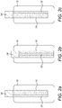
- Figures 2a to 2c where the rotation of the aerosol generating substrate 32 is depicted schematically by a shaded area that represents a previously heated portion of the aerosol generating substrate 32. In practice, there will be multiple previously heated portions as the aerosol generating substrate 32 is incrementally rotated during use, but only a single heated portion is shown in Figures 2a to 2c for illustration purposes.
- the aerosol generating device 10 includes a capture element 50 which is fixed to an inner surface of the compartment 18.
- the capture element 50 includes a plurality of circumferentially spaced second engaging formations 52 and can have a generally tubular construction which conforms to the circular cross-section of the compartment 18.
- Each of the second engaging formations 52 includes a flat surface 52a which extends in a direction substantially parallel to the longitudinal axis of the compartment 18 and an inclined surface 52b which is inclined relative to the longitudinal axis of the compartment 18.
- the support element 44 is movable in the compartment 18 along the longitudinal axis, in addition to being rotatable in the compartment 18 as described above. More particularly, the support element 44 is movable in the compartment 18 along the longitudinal axis between a first position shown in Figure 3a and a second position shown in Figure 3b . When the support element 44 is in the first position shown in Figure 3a , the flat surfaces 48a, 52a respectively of the first and second engaging formations 48, 52 cooperate to prevent rotational movement of the support element 44 in the compartment 18.
- the aerosol generating device 10 includes a biasing element 54, for example in the form of a spring, which biases the support element 44 to the first position in the compartment 18 as shown in Figure 3a .
- the biasing element 54 is positioned at the closed end 22 of the compartment 18 and urges the support element 44 in the longitudinal direction from the closed end 22 towards the open end 20, such that the first and second engaging formations 48, 52 are biased into cooperating engagement with each other.
- the aerosol generating device 10 includes a release element 56 which is movable in the compartment 18 along the longitudinal axis.
- the release element 56 includes a plurality of circumferentially spaced third engaging formations 58 (see Figure 3b ) and can have a generally tubular construction which conforms to the circular cross-section of the compartment 18.
- the third engaging formations 58 include inclined surfaces 58a, 58b which are inclined relative to the longitudinal axis of the compartment 18 and which together formed a toothed profile.
- the release element 56 is user actuable, in other words is movable in the compartment 18 along the longitudinal axis upon actuation by a user.
- the aerosol generating device 10 includes an actuating member 60, for example in the form of a slider as illustrated in Figure 1 , which can be moved by a user along a longitudinally extending channel in the side of the housing 16.
- the actuating member 60 is connected to, or integral with, the release element 56 so that as a user slides the actuating member 60 from the position shown in Figure 1 adjacent to the open end 20 of the compartment 18 in a direction towards the closed end 22 of the compartment 18, the release element 56 is moved from the position shown in Figure 3a to the position shown in Figure 3b .
- Movement of the release element 56 from the position shown in Figure 3a to the position shown in Figure 3b causes the third engaging formations 58 of the release element 56 to engage the first engaging formations 48 of the support element 44.
- the support element 44 is thereby moved from the first position shown in Figure 3a to the second position shown in Figure 3b by the release element 56, thereby disengaging the first and second engaging formations 48, 52 respectively of the support element 44 and capture element 50.
- the cooperation between the inclined surfaces 58b of the third engaging formations 58 and the inclined surfaces 48b of the first engaging formations 48 imparts a rotational force to the first engaging formations 48 and thereby causes the support element 44 to rotate in the compartment 18. This in turn initiates rotational movement of the aerosol generating substrate 32 that is supported by the support element 44.
- the support element 44 is biased by the biasing element 54 towards the first position.
- the inclined surfaces 48b of the first engaging formations 48 of the support element 48 cooperate with the inclined surfaces 52b of the second engaging formations 52 of the capture element 50 as best seen in Figure 3c .
- Rotational movement of the support element 44, and hence of the aerosol generating substrate 32 ceases when the flat surfaces 48a of the first engaging formations 48 of the support element 44 engage the flat surfaces 52a of the second engaging formations 52 of the capture element 50 as shown in Figure 3d .
- the support element 44, and hence the aerosol generating substrate 32 has been subjected to an indexed rotational movement in the compartment 18.
- a fresh (i.e. previously unheated) portion of the aerosol generating substrate 32 is positioned adjacent to the heating element 42 whilst a previously heated portion of the aerosol generating substrate is moved away from the heating element 42, as shown schematically in Figures 2a to 2c .
- the heating element 42 extends only partially around the circumference of the compartment 18, for example about one-eighth of the circumference of the compartment 18 in the illustrated embodiment.
- the first, second and third engaging formations 48, 52, 58 are, therefore, arranged respectively on the support element 44, capture element 50 and release element 56 so that when the actuating member 60 is operated by a user, the support element 44, and hence the aerosol generating substrate 32, is subjected to an indexed rotational movement which corresponds substantially to the circumferential distance that the heating element 42 extends around the compartment 18.
- the controller 26 may be configured to detect the consumption of the aerosol generating substrate 32, e.g., by detecting the number of inhalations or 'puffs' by a user of the aerosol generating device 10 or by detecting that a predetermined period of time has elapsed with the aerosol generating substrate 32 in a predetermined indexed rotational position. After detecting a predetermined number of puffs or after detecting that a predetermined period of time has elapsed, the controller 26 may be configured to generate a user alert to prompt a user of the aerosol generating device 10 to operate the actuating member 60 and thereby initiate an indexed rotational movement of the aerosol generating substrate 32 so that a fresh and unused (i.e.
- the controller 26 may be configured to generate a user alert to prompt a user to remove the used aerosol generating article 30 from the compartment 18 and to insert a replacement (i.e. previously unused) aerosol generating article 30 into the compartment 18.
Landscapes
- Catching Or Destruction (AREA)
- Containers And Packaging Bodies Having A Special Means To Remove Contents (AREA)
Abstract
Description
- The present disclosure relates generally to an aerosol generating device, and more particularly to an aerosol generating device for heating an aerosol generating substrate to generate an aerosol for inhalation by a user. Embodiments of the present disclosure also relate to an aerosol generating system.
- Devices which heat, rather than burn, an aerosol generating substrate to produce an aerosol for inhalation have become popular with consumers in recent years. Such devices can use one of a number of different approaches to provide heat to the aerosol generating substrate.
- One approach is to provide an aerosol generating device which employs a resistive heating system. In such a device, a resistive heating element is provided to heat aerosol generating substrate positioned within a cavity of the device and thereby generate a vapour which typically cools and condenses to form an aerosol for inhalation by a user of the device.
- The resistive heating system can be an internal resistive heating system in which one or more resistive heating elements (e.g. a heating blade arranged within the cavity of the device) are arranged to be positioned within the aerosol generating substrate during use of the aerosol generating device and/or an external resistive heating system in which one or more resistive heating elements are arranged to at least partially surround the aerosol generating substrate.
- It would be desirable to provide an aerosol generating device and an aerosol generating system which has a reduced power requirement and/or which provides improved control over the heating of the aerosol generating substrate.
- According to a first aspect of the present disclosure, there is provided an aerosol generating device comprising:
- a housing defining a compartment for receiving an aerosol generating substrate, the compartment having an open end, a closed end and a longitudinal axis extending between the open and closed ends;
- a stationary heater positioned adjacent to an outer surface of the aerosol generating substrate and arranged to heat a portion of the aerosol generating substrate positioned adjacent to the heater;
- a support element in the compartment for supporting the aerosol generating substrate, the support element including a plurality of circumferentially spaced first engaging formations;
- a capture element fixed to an inner surface of the compartment, the capture element including a plurality of circumferentially spaced second engaging formations;
- a release element movable in the compartment along the longitudinal axis upon actuation by a user, the release element including a plurality of circumferentially spaced third engaging formations;
- wherein:
- the support element is rotatable about the longitudinal axis to provide indexed rotational movement of the aerosol generating substrate in the compartment to sequentially position portions of the outer surface of the aerosol generating substrate adjacent to the heater;
- the support element is movable in the compartment along the longitudinal axis between first and second positions and is biased to the first position, the first and second engaging formations cooperate when the support element is in the first position to prevent rotational movement of the support element in the compartment, and the first and second engaging formations do not cooperate when the support element is in the second position to allow rotational movement of the support element in the compartment; and
- upon actuation of the release element by a user, the third engaging formations are configured to engage the first engaging formations to move the support element from the first position to the second position to disengage the first and second engaging formations and thereby permit indexed rotational movement of the support element, and corresponding indexed rotational movement of the aerosol generating substrate, in the compartment.
- The aerosol generating device is adapted to heat the aerosol generating substrate, without burning the aerosol generating substrate, to volatise at least one component of the aerosol generating substrate and thereby generate a vapour which cools and condenses to form an aerosol for inhalation by a user of the aerosol generating device.
- In general terms, a vapour is a substance in the gas phase at a temperature lower than its critical temperature, which means that the vapour can be condensed to a liquid by increasing its pressure without reducing the temperature, whereas an aerosol is a suspension of fine solid particles or liquid droplets, in air or another gas. It should, however, be noted that the terms 'aerosol' and 'vapour' may be used interchangeably in this specification, particularly with regard to the form of the inhalable medium that is generated for inhalation by a user.
- By providing indexed rotational movement of the aerosol generating substrate in the compartment, it is possible to heat specific portions of the aerosol generating substrate and thereby provide controlled heating of the aerosol generating substrate to generate an aerosol with suitable characteristics for inhalation by a user. The need to heat the whole of the aerosol generating substrate to generate an aerosol is thereby avoided, meaning that a smaller heater can be used. By using a smaller heater, the amount of energy required to raise the heater to a sufficient temperature to cause aerosol generation can be reduced, thus resulting in an aerosol generating device with improved energy efficiency.
- The support element may be configured to engage the aerosol generating substrate to retain the aerosol generating substrate in the compartment and such that the aerosol generating substrate rotates in unison with the support element. The support element may include a retainer to retain the aerosol generating substrate on the support element. The aerosol generating substrate is thereby securely retained in the compartment by the support element and subjected to indexed rotational movement by the support element to sequentially position fresh and unused portions of the outer surface of the aerosol generating substrate adjacent to the heater.
- The support element may be positioned proximate the closed end of the compartment. The device may include a biasing element, for example a spring, which may be arranged to bias the support element to the first position. The biasing element may be positioned at the closed end of the compartment. When the support element is biased to the first position by the biasing element, the aerosol generating substrate is securely retained in its indexed rotational position by virtue of the cooperation between the first and second engaging formations.
- The third engaging formations may be configured to impart a rotational force to the first engaging formations when the first and second engaging formations are disengaged to thereby rotate the support element in the compartment. The engagement between the third engaging formations and the first engaging formations thus provides for reliable indexed rotational movement of the support element and, hence, corresponding indexed rotational movement of the aerosol generating substrate in the compartment.
- Each of the third engaging formations may include an inclined surface which may be inclined relative to the longitudinal axis of the compartment and which may be configured to impart said rotational force to the first engaging formations.
- The second engaging formations may be configured to impart a rotational force to the first engaging formations during biased movement of the support element from the second position to the first position to thereby rotate the support element in the compartment. The engagement between the second engaging formations and the first engaging formations during biased movement of the support element provides for further indexed rotational movement of the support element and, hence, corresponding indexed rotational movement of the aerosol generating substrate in the compartment to ensure that a fresh and unused portion of the aerosol generating substrate is positioned adjacent to the heater upon completion of the rotational movement.
- Each of the first and second engaging formations may include an inclined surface which may be inclined relative to the longitudinal axis of the compartment. The inclined surfaces may be configured to cooperate with each other to impart said rotational force.
- Each of the first and second engaging formations may include a flat surface which is substantially parallel to the longitudinal axis of the compartment. The flat surfaces are configured to cooperate with each other when the support element is biased to the first position to prevent rotational movement of the support element in the compartment. The cooperation between the flat surfaces thus securely retains the support element and, hence, the aerosol generating substrate in a predetermined indexed rotational position.
- The support element may be configured to rotate in substantially equal predetermined rotational increments. Consistent heating of the aerosol generating substrate is thereby assured.
- Each predetermined rotational increment may correspond substantially to a distance that the heater extends around an inner surface of the compartment. For example, the heater may extend up to about 180 degrees around the inner surface of the compartment, possibly up to about 90 degrees around the inner surface of the compartment, and possibly between about 30 degrees and 60 degrees around the inner surface of the compartment. For example, if the heater extends about 45 degrees around the inner surface of the compartment (i.e. about one-eighth of the inner circumference), each predetermined rotational increment may be about 45 degrees.
- The heater may have any suitable length. The heater may have a length in the direction of the longitudinal axis of the compartment which is less than the length of the compartment.
- The heater may comprise any suitable heating element. For example, the heating element may comprise a resistive heating element or an inductive heating element, such as an inductively heatable susceptor. Typically, the heating element comprises a resistive heating element comprising an electrically resistive material. Examples of suitable electrically resistive materials include, but are not limited to, metals, metal alloys, electrically conductive ceramics, for example tungsten and alloys thereof, and composite materials comprising a metallic material and a ceramic material.
- According to a second aspect of the present disclosure, there is provided an aerosol generating system comprising an aerosol generating device as defined above and an aerosol generating substrate positioned in the compartment.
- The compartment and the aerosol generating substrate may have a substantially circular cross-section. Thus, the compartment may be substantially cylindrical and the aerosol generating substrate may be substantially cylindrical.
- The aerosol generating substrate may be circumscribed by a paper wrapper, such that the aerosol generating substrate and the paper wrapper form an aerosol generating article. The aerosol generating article may be formed substantially in the shape of a rod or stick. The aerosol generating article may include a filter, for example comprising cellulose acetate fibres. The filter may be in abutting coaxial alignment with the aerosol generating substrate.
- The aerosol generating substrate may be any type of solid or semi-solid material. Example types of aerosol generating solids include powder, granules, pellets, shreds, strands, particles, gel, strips, loose leaves, cut leaves, cut filler, porous material, foam material or sheets. The aerosol generating substrate may comprise plant derived material and in particular, may comprise tobacco. It may advantageously comprise reconstituted tobacco.
- The aerosol generating substrate may comprise an aerosol-former. Examples of aerosol-formers include polyhydric alcohols and mixtures thereof such as glycerine or propylene glycol. Typically, the aerosol generating substrate may comprise an aerosol-former content of between approximately 5% and approximately 50% on a dry weight basis. In some embodiments, the aerosol generating substrate may comprise an aerosol-former content of between approximately 10% and approximately 20% on a dry weight basis, and possibly approximately 15% on a dry weight basis.
- Upon heating, the aerosol generating substrate may release volatile compounds. The volatile compounds may include nicotine or flavour compounds such as tobacco flavouring.
-
-
Figure 1 is a diagrammatic cross-sectional view of an aerosol generating system comprising an aerosol generating device and an aerosol generating article which together form an aerosol generating system; -
Figures 2a to 2c are diagrammatic views of the part of the aerosol generating system ofFigure 1 , schematically illustrating indexed rotational movement of an aerosol generating substrate; and -
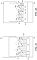
Figures 3a to 3d are enlarged diagrammatic views of the region labelled A inFigure 1 , illustrating part of a mechanism that provides the indexed rotational movement illustrated inFigures 2a to 2c . - Embodiments of the present disclosure will now be described by way of example only and with reference to the accompanying drawings.
- Referring initially to
Figure 1 , there is shown diagrammatically an example of an aerosol generating system 1. The aerosol generating system 1 comprises anaerosol generating device 10 and anaerosol generating article 30. Theaerosol generating device 10 has aproximal end 12 and adistal end 14 and comprises ahousing 16 which defines acompartment 18 for receiving theaerosol generating article 30. Thecompartment 18, which may be substantially circular in cross-section, has anopen end 20 at theproximal end 12 of theaerosol generating device 10 to permit insertion and removal of anaerosol generating article 30, aclosed end 22 at thedistal end 14 of theaerosol generating device 10, and a longitudinal axis which extends between theopen end 20 and theclosed end 22. Thehousing 16 can include one or more air inlets (not shown), typically at thedistal end 14 of theaerosol generating device 10, for supplying air to thecompartment 18. Theaerosol generating device 10 also includes apower source 24 and acontroller 26. Thepower source 24 typically comprises one or more batteries which could be removable/replaceable and/or rechargeable, for example by connecting theaerosol generating device 10 to a charger via acharger connection 28. - The
aerosol generating article 30 is a disposable article and comprises anaerosol generating substrate 32, for example tobacco, having afirst end 32a and asecond end 32b. Theaerosol generating article 30 is substantially stick-shaped or rod-shaped and has a substantially circular cross-section which generally conforms to the circular cross-section of thecompartment 18. Theaerosol generating article 30 typically comprises a paper wrapper (not shown) surrounding theaerosol generating substrate 32. Theaerosol generating article 30 comprises afilter 34 at one end (the mouth end) which is in abutting coaxial alignment with thefirst end 32a of theaerosol generating substrate 32. Thefilter 34 acts as a mouthpiece and comprises an air-permeable plug, for example comprising cellulose acetate fibres. Both the paper wrapper and thefilter 34 are overwrapped by an outer wrapper (not shown) typically comprising tipping paper. - The
aerosol generating device 10 includes a stationary heater 40 for heating theaerosol generating substrate 32. The heater 40 can comprise a generally elongate resistive heating element 42 which is arranged substantially parallel to the longitudinal axis of thecompartment 18 and which extends from theopen end 20 towards theclosed end 22, for a distance which may be less than the length of thecompartment 18 in the longitudinal direction. The heating element 42 is positioned adjacent to anouter surface 36 of theaerosol generating substrate 32 as best seen inFigure 1 and has a surface which is exposed to the interior of thecompartment 18 so that it can heat theaerosol generating substrate 32. The heating element 42 extends only partially around the circumference of thecompartment 18. In the illustrated embodiment, the heating element 42 extends about a portion of the circumference, preferably between about one-tenth and half of the circumference, for example about one-eighth of the circumference of thecompartment 18. In other words, the heating element 42 extends about 45 degrees of the circumference of thecompartment 18. Thus, the heating element 42 is arranged to heat only a portion of theaerosol generating substrate 32, and more particularly a portion of theaerosol generating substrate 32 that is positioned adjacent to the heating element 42. - Referring also to
Figures 3a to 3d , theaerosol generating device 10 includes asupport element 44 positioned at theclosed end 22 of thecompartment 18. Thesupport element 44 has a substantially circular cross-section and supports theaerosol generating substrate 32 at thesecond end 32b. Thesupport element 44 is configured to engage thesecond end 32b of theaerosol generating substrate 32 to retain theaerosol generating substrate 32 in thecompartment 18. - The
support element 44 includes a plurality of circumferentially spaced first engagingformations 48 which extend in the longitudinal direction, from thesecond end 32b of theaerosol generating substrate 32 towards thefirst end 32a. The circumferentially spaced first engagingformations 48 encircle theaerosol generating substrate 32 at thesecond end 32b and can act as a retainer 46 (seeFigure 1 ) to retain theaerosol generating substrate 32 on thesupport element 44. In alternative embodiments (not illustrated), the retainer 46 could comprise one or more projections that extend from a surface of thesupport element 44 and into theaerosol generating substrate 32. Each of the first engagingformations 48 includes aflat surface 48a which extends in a direction substantially parallel to the longitudinal axis of thecompartment 18 and aninclined surface 48b which is inclined relative to the longitudinal axis of thecompartment 18. - The
support element 44 is rotatable in thecompartment 18 about the longitudinal axis, and thus provides for corresponding rotational movement of theaerosol generating article 30, and more particularly theaerosol generating substrate 32, in thecompartment 18. This rotational movement enables portions of theouter surface 36 of theaerosol generating substrate 32 to be positioned adjacent to the heating element 42, so that successive portions of theaerosol generating substrate 32 can be heated by heat transferred from the heating element 42. This is illustrated diagrammatically inFigures 2a to 2c , where the rotation of theaerosol generating substrate 32 is depicted schematically by a shaded area that represents a previously heated portion of theaerosol generating substrate 32. In practice, there will be multiple previously heated portions as theaerosol generating substrate 32 is incrementally rotated during use, but only a single heated portion is shown inFigures 2a to 2c for illustration purposes. - The
aerosol generating device 10 includes acapture element 50 which is fixed to an inner surface of thecompartment 18. Thecapture element 50 includes a plurality of circumferentially spaced second engagingformations 52 and can have a generally tubular construction which conforms to the circular cross-section of thecompartment 18. Each of the secondengaging formations 52 includes aflat surface 52a which extends in a direction substantially parallel to the longitudinal axis of thecompartment 18 and aninclined surface 52b which is inclined relative to the longitudinal axis of thecompartment 18. - The
support element 44 is movable in thecompartment 18 along the longitudinal axis, in addition to being rotatable in thecompartment 18 as described above. More particularly, thesupport element 44 is movable in thecompartment 18 along the longitudinal axis between a first position shown inFigure 3a and a second position shown inFigure 3b . When thesupport element 44 is in the first position shown inFigure 3a , theflat surfaces formations support element 44 in thecompartment 18. On the other hand, when thesupport element 44 is in the second position shown inFigure 3b , theflat surfaces formations support element 44 in thecompartment 18. It will, thus, be understood that when thesupport element 44 is in the first position, rotation of theaerosol generating substrate 32 in thecompartment 18 is prevented, whereas when thesupport element 44 is in the second position, rotation of theaerosol generating substrate 32 in thecompartment 18 is permitted. - The
aerosol generating device 10 includes a biasingelement 54, for example in the form of a spring, which biases thesupport element 44 to the first position in thecompartment 18 as shown inFigure 3a . The biasingelement 54 is positioned at theclosed end 22 of thecompartment 18 and urges thesupport element 44 in the longitudinal direction from theclosed end 22 towards theopen end 20, such that the first and second engagingformations - The
aerosol generating device 10 includes arelease element 56 which is movable in thecompartment 18 along the longitudinal axis. Therelease element 56 includes a plurality of circumferentially spaced third engaging formations 58 (seeFigure 3b ) and can have a generally tubular construction which conforms to the circular cross-section of thecompartment 18. The thirdengaging formations 58 includeinclined surfaces compartment 18 and which together formed a toothed profile. Therelease element 56 is user actuable, in other words is movable in thecompartment 18 along the longitudinal axis upon actuation by a user. Theaerosol generating device 10 includes an actuatingmember 60, for example in the form of a slider as illustrated inFigure 1 , which can be moved by a user along a longitudinally extending channel in the side of thehousing 16. The actuatingmember 60 is connected to, or integral with, therelease element 56 so that as a user slides the actuatingmember 60 from the position shown inFigure 1 adjacent to theopen end 20 of thecompartment 18 in a direction towards theclosed end 22 of thecompartment 18, therelease element 56 is moved from the position shown inFigure 3a to the position shown inFigure 3b . - Movement of the
release element 56 from the position shown inFigure 3a to the position shown inFigure 3b causes the thirdengaging formations 58 of therelease element 56 to engage the first engagingformations 48 of thesupport element 44. Thesupport element 44 is thereby moved from the first position shown inFigure 3a to the second position shown inFigure 3b by therelease element 56, thereby disengaging the first and second engagingformations support element 44 andcapture element 50. The cooperation between theinclined surfaces 58b of the thirdengaging formations 58 and theinclined surfaces 48b of the first engagingformations 48 imparts a rotational force to the first engagingformations 48 and thereby causes thesupport element 44 to rotate in thecompartment 18. This in turn initiates rotational movement of theaerosol generating substrate 32 that is supported by thesupport element 44. - The movement of the
support element 44 by therelease element 56 along the longitudinal axis of thecompartment 18 compresses the biasingelement 54 between thesupport element 44 and theclosed end 22 of thecompartment 18. Thus, when the actuatingmember 60 is released by a user to return therelease element 56 to the position illustrated inFigure 3c , thesupport element 44 is biased by the biasingelement 54 towards the first position. As thesupport element 44 is biased towards the first position, theinclined surfaces 48b of the first engagingformations 48 of thesupport element 48 cooperate with theinclined surfaces 52b of the secondengaging formations 52 of thecapture element 50 as best seen inFigure 3c . The cooperation between theinclined surfaces 52b of the secondengaging formations 52 and theinclined surfaces 48b of the first engagingformations 48 imparts a rotational force to the first engagingformations 48 and thereby causes thesupport element 44 to continue its rotational movement in thecompartment 18. This in turn causes continued rotational movement of theaerosol generating substrate 32 that is supported by thesupport element 44. - Rotational movement of the
support element 44, and hence of theaerosol generating substrate 32, ceases when theflat surfaces 48a of the first engagingformations 48 of thesupport element 44 engage theflat surfaces 52a of the secondengaging formations 52 of thecapture element 50 as shown inFigure 3d . At this point, it will be understood that thesupport element 44, and hence theaerosol generating substrate 32, has been subjected to an indexed rotational movement in thecompartment 18. By virtue of this indexed rotational movement, a fresh (i.e. previously unheated) portion of theaerosol generating substrate 32 is positioned adjacent to the heating element 42 whilst a previously heated portion of the aerosol generating substrate is moved away from the heating element 42, as shown schematically inFigures 2a to 2c . - As explained above, the heating element 42 extends only partially around the circumference of the
compartment 18, for example about one-eighth of the circumference of thecompartment 18 in the illustrated embodiment. The first, second and thirdengaging formations support element 44,capture element 50 andrelease element 56 so that when the actuatingmember 60 is operated by a user, thesupport element 44, and hence theaerosol generating substrate 32, is subjected to an indexed rotational movement which corresponds substantially to the circumferential distance that the heating element 42 extends around thecompartment 18. - In some embodiments, the
controller 26 may be configured to detect the consumption of theaerosol generating substrate 32, e.g., by detecting the number of inhalations or 'puffs' by a user of theaerosol generating device 10 or by detecting that a predetermined period of time has elapsed with theaerosol generating substrate 32 in a predetermined indexed rotational position. After detecting a predetermined number of puffs or after detecting that a predetermined period of time has elapsed, thecontroller 26 may be configured to generate a user alert to prompt a user of theaerosol generating device 10 to operate the actuatingmember 60 and thereby initiate an indexed rotational movement of theaerosol generating substrate 32 so that a fresh and unused (i.e. previously unheated) portion of theaerosol generating substrate 32 is positioned adjacent to the heating element 42. In this way, portions of theaerosol generating substrate 32 can be sequentially heated by the heating element 42. When theaerosol generating substrate 32 has been fully heated and depleted, thecontroller 26 may be configured to generate a user alert to prompt a user to remove the usedaerosol generating article 30 from thecompartment 18 and to insert a replacement (i.e. previously unused)aerosol generating article 30 into thecompartment 18. - Although exemplary embodiments have been described in the preceding paragraphs, it should be understood that various modifications may be made to those embodiments without departing from the scope of the appended claims. Thus, the breadth and scope of the claims should not be limited to the above-described exemplary embodiments.
- Any combination of the above-described features in all possible variations thereof is encompassed by the present disclosure unless otherwise indicated herein or otherwise clearly contradicted by context.
- Unless the context clearly requires otherwise, throughout the description and the claims, the words "comprise", "comprising", and the like, are to be construed in an inclusive as opposed to an exclusive or exhaustive sense; that is to say, in the sense of "including, but not limited to".
Claims (14)
- An aerosol generating device (10) comprising:a housing (16) defining a compartment (18) for receiving an aerosol generating substrate (32), the compartment (18) having an open end (20), a closed end (22) and a longitudinal axis extending between the open and closed ends (20, 22);a stationary heater (40) positioned adjacent to an outer surface (36) of the aerosol generating substrate (32) and arranged to heat a portion of the aerosol generating substrate (32) positioned adjacent to the heater (40);a support element (44) in the compartment (18) for supporting the aerosol generating substrate (32), the support element (44) including a plurality of circumferentially spaced first engaging formations (48);a capture element (50) fixed to an inner surface of the compartment (18), the capture element (50) including a plurality of circumferentially spaced second engaging formations (52);a release element (56) movable in the compartment (18) along the longitudinal axis upon actuation by a user, the release element (56) including a plurality of circumferentially spaced third engaging formations (58);wherein:the support element (44) is rotatable about the longitudinal axis to provide indexed rotational movement of the aerosol generating substrate (32) in the compartment (18) to sequentially position portions of the outer surface (36) of the aerosol generating substrate (32) adjacent to the heater (40);the support element (44) is movable in the compartment (18) along the longitudinal axis between first and second positions and is biased to the first position, the first and second engaging formations (48, 52) cooperate when the support element (44) is in the first position to prevent rotational movement of the support element (44) in the compartment (18), and the first and second engaging formations (48, 52) do not cooperate when the support element (44) is in the second position to allow rotational movement of the support element (44) in the compartment (18); andupon actuation of the release element (56) by a user, the third engaging formations (58) are configured to engage the first engaging formations (48) to move the support element (44) from the first position to the second position to disengage the first and second engaging formations (48, 52) and thereby permit indexed rotational movement of the support element (44), and corresponding indexed rotational movement of the aerosol generating substrate (32), in the compartment (18).
- An aerosol generating device according to claim 1, wherein the support element (44) is configured to engage the aerosol generating substrate (32) to retain the aerosol generating substrate (32) in the compartment (18) and such that the aerosol generating substrate (32) rotates in unison with the support element (44).
- An aerosol generating device according to claim 2, wherein the support element (44) includes a retainer (46) to retain the aerosol generating substrate (32) on the support element (44).
- An aerosol generating device according to any preceding claim, wherein the support element (44) is positioned proximate the closed end (22) of the compartment (18).
- An aerosol generating device according to any preceding claim, wherein the device (10) includes a biasing element (54) to bias the support element (44) to the first position, preferably wherein the biasing element (54) is positioned at the closed end (22) of the compartment (18).
- An aerosol generating device according to any preceding claim, wherein the third engaging formations (58) are configured to impart a rotational force to the first engaging formations (48) when the first and second engaging formations (48, 52) are disengaged to thereby rotate the support element (44) in the compartment (18).
- An aerosol generating device according to claim 6, wherein each of the third engaging formations (58) includes an inclined surface (58a, 58b) which is inclined relative to the longitudinal axis of the compartment (18) and configured to impart said rotational force to the first engaging formations (48).
- An aerosol generating device according to any preceding claim, wherein the second engaging formations (52) are configured to impart a rotational force to the first engaging formations (48) during biased movement of the support element (44) from the second position to the first position to thereby rotate the support element (44) in the compartment (18).
- An aerosol generating device according to claim 8, wherein each of the first and second engaging formations (48, 52) includes an inclined surface (48b, 52b) which is inclined relative to the longitudinal axis of the compartment (18), and wherein the inclined surfaces (48b, 52b) are configured to cooperate with each other to impart said rotational force.
- An aerosol generating device according to claim 9, wherein each of the first and second engaging formations (48, 52) includes a flat surface (48a, 52a) which is substantially parallel to the longitudinal axis of the compartment (18), and wherein the flat surfaces (48a, 52a) are configured to cooperate with each other when the support element (44) is biased to the first position to prevent rotational movement of the support element (44) in the compartment (18).
- An aerosol generating device according to any preceding claim, wherein the support element (44) is configured to rotate in substantially equal predetermined rotational increments.
- An aerosol generating device according to claim 11, wherein each predetermined rotational increment corresponds substantially to a distance that the heater (40) extends around an inner surface of the compartment (18).
- An aerosol generating system comprising an aerosol generating device (10) according to any preceding claim and an aerosol generating substrate (32) positioned in the compartment (18).
- An aerosol generating system according to claim 13, wherein the compartment (18) and the aerosol generating substrate (32) have a substantially circular cross-section.
Priority Applications (1)
| Application Number | Priority Date | Filing Date | Title |
|---|---|---|---|
| EP19206604.1A EP3815554B1 (en) | 2019-10-31 | 2019-10-31 | Aerosol generating device and system |
Applications Claiming Priority (1)
| Application Number | Priority Date | Filing Date | Title |
|---|---|---|---|
| EP19206604.1A EP3815554B1 (en) | 2019-10-31 | 2019-10-31 | Aerosol generating device and system |
Publications (2)
| Publication Number | Publication Date |
|---|---|
| EP3815554A1 true EP3815554A1 (en) | 2021-05-05 |
| EP3815554B1 EP3815554B1 (en) | 2022-08-31 |
Family
ID=68426131
Family Applications (1)
| Application Number | Title | Priority Date | Filing Date |
|---|---|---|---|
| EP19206604.1A Active EP3815554B1 (en) | 2019-10-31 | 2019-10-31 | Aerosol generating device and system |
Country Status (1)
| Country | Link |
|---|---|
| EP (1) | EP3815554B1 (en) |
Cited By (4)
| Publication number | Priority date | Publication date | Assignee | Title |
|---|---|---|---|---|
| CN114223966A (en) * | 2021-12-28 | 2022-03-25 | 海南摩尔兄弟科技有限公司 | Atomization device |
| WO2024174661A1 (en) * | 2023-02-20 | 2024-08-29 | 思摩尔国际控股有限公司 | Heater and aerosol generating device |
| WO2024235174A1 (en) * | 2023-05-12 | 2024-11-21 | 思摩尔国际控股有限公司 | Atomizing medium assembly and aerosol generating apparatus |
| CN119014613A (en) * | 2023-05-25 | 2024-11-26 | 思摩尔国际控股有限公司 | Heat without burning device and control method thereof |
Citations (2)
| Publication number | Priority date | Publication date | Assignee | Title |
|---|---|---|---|---|
| US6053176A (en) * | 1999-02-23 | 2000-04-25 | Philip Morris Incorporated | Heater and method for efficiently generating an aerosol from an indexing substrate |
| WO2019016740A1 (en) * | 2017-07-21 | 2019-01-24 | Philip Morris Products S.A. | Aerosol generating device with spiral movement for heating |
-
2019
- 2019-10-31 EP EP19206604.1A patent/EP3815554B1/en active Active
Patent Citations (2)
| Publication number | Priority date | Publication date | Assignee | Title |
|---|---|---|---|---|
| US6053176A (en) * | 1999-02-23 | 2000-04-25 | Philip Morris Incorporated | Heater and method for efficiently generating an aerosol from an indexing substrate |
| WO2019016740A1 (en) * | 2017-07-21 | 2019-01-24 | Philip Morris Products S.A. | Aerosol generating device with spiral movement for heating |
Cited By (7)
| Publication number | Priority date | Publication date | Assignee | Title |
|---|---|---|---|---|
| CN114223966A (en) * | 2021-12-28 | 2022-03-25 | 海南摩尔兄弟科技有限公司 | Atomization device |
| WO2023124520A1 (en) * | 2021-12-28 | 2023-07-06 | 海南摩尔兄弟科技有限公司 | Atomization device |
| CN114223966B (en) * | 2021-12-28 | 2025-09-26 | 海南摩尔兄弟科技有限公司 | Atomization device |
| WO2024174661A1 (en) * | 2023-02-20 | 2024-08-29 | 思摩尔国际控股有限公司 | Heater and aerosol generating device |
| WO2024235174A1 (en) * | 2023-05-12 | 2024-11-21 | 思摩尔国际控股有限公司 | Atomizing medium assembly and aerosol generating apparatus |
| CN119014613A (en) * | 2023-05-25 | 2024-11-26 | 思摩尔国际控股有限公司 | Heat without burning device and control method thereof |
| WO2024239908A1 (en) * | 2023-05-25 | 2024-11-28 | 思摩尔国际控股有限公司 | Heat-not-burn device and control method thereof |
Also Published As
| Publication number | Publication date |
|---|---|
| EP3815554B1 (en) | 2022-08-31 |
Similar Documents
| Publication | Publication Date | Title |
|---|---|---|
| KR102449404B1 (en) | Aerosol-generating device having fixing means | |
| EP3815554B1 (en) | Aerosol generating device and system | |
| US11478590B2 (en) | Aerosol generating device with spiral movement for heating | |
| JP7344219B2 (en) | Aerosol delivery device with indexing action | |
| EP3784078B1 (en) | Smoking article, smoking system and method for aerosol generation | |
| CN109195464B (en) | Electrically operated aerosol generating system with a tubular aerosol generating article | |
| EP4326106B1 (en) | Aerosol generating device comprising an expandable container | |
| EP4326099A1 (en) | An aerosol generating article and method of manufacturing the same, and an aerosol generating system | |
| EP4337044B1 (en) | Aerosol generating device with hinged lid and mouthpiece | |
| JP7805305B2 (en) | Aerosol generating device | |
| US20250234927A1 (en) | An Aerosol Generating Device | |
| EP4051030B1 (en) | Aerosol generating device and system | |
| WO2022223711A1 (en) | An aerosol generating article and method of manufacturing the same | |
| KR20230142531A (en) | Induction heating assembly for aerosol generating device | |
| EP4241590A1 (en) | An aerosol generating system comprising a disabling element | |
| US20250072507A1 (en) | Aerosol generating device |
Legal Events
| Date | Code | Title | Description |
|---|---|---|---|
| PUAI | Public reference made under article 153(3) epc to a published international application that has entered the european phase |
Free format text: ORIGINAL CODE: 0009012 |
|
| STAA | Information on the status of an ep patent application or granted ep patent |
Free format text: STATUS: THE APPLICATION HAS BEEN PUBLISHED |
|
| AK | Designated contracting states |
Kind code of ref document: A1 Designated state(s): AL AT BE BG CH CY CZ DE DK EE ES FI FR GB GR HR HU IE IS IT LI LT LU LV MC MK MT NL NO PL PT RO RS SE SI SK SM TR |
|
| STAA | Information on the status of an ep patent application or granted ep patent |
Free format text: STATUS: REQUEST FOR EXAMINATION WAS MADE |
|
| 17P | Request for examination filed |
Effective date: 20211026 |
|
| RBV | Designated contracting states (corrected) |
Designated state(s): AL AT BE BG CH CY CZ DE DK EE ES FI FR GB GR HR HU IE IS IT LI LT LU LV MC MK MT NL NO PL PT RO RS SE SI SK SM TR |
|
| GRAP | Despatch of communication of intention to grant a patent |
Free format text: ORIGINAL CODE: EPIDOSNIGR1 |
|
| STAA | Information on the status of an ep patent application or granted ep patent |
Free format text: STATUS: GRANT OF PATENT IS INTENDED |
|
| RIC1 | Information provided on ipc code assigned before grant |
Ipc: A24F 40/40 20200101ALI20220314BHEP Ipc: A24F 40/00 20200101AFI20220314BHEP |
|
| INTG | Intention to grant announced |
Effective date: 20220405 |
|
| GRAS | Grant fee paid |
Free format text: ORIGINAL CODE: EPIDOSNIGR3 |
|
| GRAA | (expected) grant |
Free format text: ORIGINAL CODE: 0009210 |
|
| STAA | Information on the status of an ep patent application or granted ep patent |
Free format text: STATUS: THE PATENT HAS BEEN GRANTED |
|
| AK | Designated contracting states |
Kind code of ref document: B1 Designated state(s): AL AT BE BG CH CY CZ DE DK EE ES FI FR GB GR HR HU IE IS IT LI LT LU LV MC MK MT NL NO PL PT RO RS SE SI SK SM TR |
|
| REG | Reference to a national code |
Ref country code: CH Ref legal event code: EP Ref country code: GB Ref legal event code: FG4D |
|
| REG | Reference to a national code |
Ref country code: AT Ref legal event code: REF Ref document number: 1514639 Country of ref document: AT Kind code of ref document: T Effective date: 20220915 |
|
| REG | Reference to a national code |
Ref country code: DE Ref legal event code: R096 Ref document number: 602019018900 Country of ref document: DE |
|
| REG | Reference to a national code |
Ref country code: IE Ref legal event code: FG4D |
|
| REG | Reference to a national code |
Ref country code: LT Ref legal event code: MG9D |
|
| REG | Reference to a national code |
Ref country code: NL Ref legal event code: MP Effective date: 20220831 |
|
| PG25 | Lapsed in a contracting state [announced via postgrant information from national office to epo] |
Ref country code: SE Free format text: LAPSE BECAUSE OF FAILURE TO SUBMIT A TRANSLATION OF THE DESCRIPTION OR TO PAY THE FEE WITHIN THE PRESCRIBED TIME-LIMIT Effective date: 20220831 Ref country code: RS Free format text: LAPSE BECAUSE OF FAILURE TO SUBMIT A TRANSLATION OF THE DESCRIPTION OR TO PAY THE FEE WITHIN THE PRESCRIBED TIME-LIMIT Effective date: 20220831 Ref country code: NO Free format text: LAPSE BECAUSE OF FAILURE TO SUBMIT A TRANSLATION OF THE DESCRIPTION OR TO PAY THE FEE WITHIN THE PRESCRIBED TIME-LIMIT Effective date: 20221130 Ref country code: LV Free format text: LAPSE BECAUSE OF FAILURE TO SUBMIT A TRANSLATION OF THE DESCRIPTION OR TO PAY THE FEE WITHIN THE PRESCRIBED TIME-LIMIT Effective date: 20220831 Ref country code: LT Free format text: LAPSE BECAUSE OF FAILURE TO SUBMIT A TRANSLATION OF THE DESCRIPTION OR TO PAY THE FEE WITHIN THE PRESCRIBED TIME-LIMIT Effective date: 20220831 Ref country code: FI Free format text: LAPSE BECAUSE OF FAILURE TO SUBMIT A TRANSLATION OF THE DESCRIPTION OR TO PAY THE FEE WITHIN THE PRESCRIBED TIME-LIMIT Effective date: 20220831 |
|
| PGFP | Annual fee paid to national office [announced via postgrant information from national office to epo] |
Ref country code: IT Payment date: 20221031 Year of fee payment: 4 |
|
| REG | Reference to a national code |
Ref country code: AT Ref legal event code: MK05 Ref document number: 1514639 Country of ref document: AT Kind code of ref document: T Effective date: 20220831 |
|
| PG25 | Lapsed in a contracting state [announced via postgrant information from national office to epo] |
Ref country code: PL Free format text: LAPSE BECAUSE OF FAILURE TO SUBMIT A TRANSLATION OF THE DESCRIPTION OR TO PAY THE FEE WITHIN THE PRESCRIBED TIME-LIMIT Effective date: 20220831 Ref country code: IS Free format text: LAPSE BECAUSE OF FAILURE TO SUBMIT A TRANSLATION OF THE DESCRIPTION OR TO PAY THE FEE WITHIN THE PRESCRIBED TIME-LIMIT Effective date: 20221231 Ref country code: HR Free format text: LAPSE BECAUSE OF FAILURE TO SUBMIT A TRANSLATION OF THE DESCRIPTION OR TO PAY THE FEE WITHIN THE PRESCRIBED TIME-LIMIT Effective date: 20220831 Ref country code: GR Free format text: LAPSE BECAUSE OF FAILURE TO SUBMIT A TRANSLATION OF THE DESCRIPTION OR TO PAY THE FEE WITHIN THE PRESCRIBED TIME-LIMIT Effective date: 20221201 |
|
| PGFP | Annual fee paid to national office [announced via postgrant information from national office to epo] |
Ref country code: CH Payment date: 20221026 Year of fee payment: 4 |
|
| PG25 | Lapsed in a contracting state [announced via postgrant information from national office to epo] |
Ref country code: SM Free format text: LAPSE BECAUSE OF FAILURE TO SUBMIT A TRANSLATION OF THE DESCRIPTION OR TO PAY THE FEE WITHIN THE PRESCRIBED TIME-LIMIT Effective date: 20220831 Ref country code: RO Free format text: LAPSE BECAUSE OF FAILURE TO SUBMIT A TRANSLATION OF THE DESCRIPTION OR TO PAY THE FEE WITHIN THE PRESCRIBED TIME-LIMIT Effective date: 20220831 Ref country code: PT Free format text: LAPSE BECAUSE OF FAILURE TO SUBMIT A TRANSLATION OF THE DESCRIPTION OR TO PAY THE FEE WITHIN THE PRESCRIBED TIME-LIMIT Effective date: 20230102 Ref country code: ES Free format text: LAPSE BECAUSE OF FAILURE TO SUBMIT A TRANSLATION OF THE DESCRIPTION OR TO PAY THE FEE WITHIN THE PRESCRIBED TIME-LIMIT Effective date: 20220831 Ref country code: DK Free format text: LAPSE BECAUSE OF FAILURE TO SUBMIT A TRANSLATION OF THE DESCRIPTION OR TO PAY THE FEE WITHIN THE PRESCRIBED TIME-LIMIT Effective date: 20220831 Ref country code: CZ Free format text: LAPSE BECAUSE OF FAILURE TO SUBMIT A TRANSLATION OF THE DESCRIPTION OR TO PAY THE FEE WITHIN THE PRESCRIBED TIME-LIMIT Effective date: 20220831 Ref country code: AT Free format text: LAPSE BECAUSE OF FAILURE TO SUBMIT A TRANSLATION OF THE DESCRIPTION OR TO PAY THE FEE WITHIN THE PRESCRIBED TIME-LIMIT Effective date: 20220831 |
|
| PG25 | Lapsed in a contracting state [announced via postgrant information from national office to epo] |
Ref country code: SK Free format text: LAPSE BECAUSE OF FAILURE TO SUBMIT A TRANSLATION OF THE DESCRIPTION OR TO PAY THE FEE WITHIN THE PRESCRIBED TIME-LIMIT Effective date: 20220831 Ref country code: MC Free format text: LAPSE BECAUSE OF FAILURE TO SUBMIT A TRANSLATION OF THE DESCRIPTION OR TO PAY THE FEE WITHIN THE PRESCRIBED TIME-LIMIT Effective date: 20220831 Ref country code: EE Free format text: LAPSE BECAUSE OF FAILURE TO SUBMIT A TRANSLATION OF THE DESCRIPTION OR TO PAY THE FEE WITHIN THE PRESCRIBED TIME-LIMIT Effective date: 20220831 |
|
| REG | Reference to a national code |
Ref country code: DE Ref legal event code: R097 Ref document number: 602019018900 Country of ref document: DE |
|
| P01 | Opt-out of the competence of the unified patent court (upc) registered |
Effective date: 20230518 |
|
| REG | Reference to a national code |
Ref country code: BE Ref legal event code: MM Effective date: 20221031 |
|
| PG25 | Lapsed in a contracting state [announced via postgrant information from national office to epo] |
Ref country code: NL Free format text: LAPSE BECAUSE OF FAILURE TO SUBMIT A TRANSLATION OF THE DESCRIPTION OR TO PAY THE FEE WITHIN THE PRESCRIBED TIME-LIMIT Effective date: 20220831 Ref country code: LU Free format text: LAPSE BECAUSE OF NON-PAYMENT OF DUE FEES Effective date: 20221031 Ref country code: AL Free format text: LAPSE BECAUSE OF FAILURE TO SUBMIT A TRANSLATION OF THE DESCRIPTION OR TO PAY THE FEE WITHIN THE PRESCRIBED TIME-LIMIT Effective date: 20220831 |
|
| PLBE | No opposition filed within time limit |
Free format text: ORIGINAL CODE: 0009261 |
|
| STAA | Information on the status of an ep patent application or granted ep patent |
Free format text: STATUS: NO OPPOSITION FILED WITHIN TIME LIMIT |
|
| 26N | No opposition filed |
Effective date: 20230601 |
|
| PG25 | Lapsed in a contracting state [announced via postgrant information from national office to epo] |
Ref country code: SI Free format text: LAPSE BECAUSE OF FAILURE TO SUBMIT A TRANSLATION OF THE DESCRIPTION OR TO PAY THE FEE WITHIN THE PRESCRIBED TIME-LIMIT Effective date: 20220831 |
|
| PG25 | Lapsed in a contracting state [announced via postgrant information from national office to epo] |
Ref country code: BE Free format text: LAPSE BECAUSE OF NON-PAYMENT OF DUE FEES Effective date: 20221031 |
|
| PG25 | Lapsed in a contracting state [announced via postgrant information from national office to epo] |
Ref country code: IE Free format text: LAPSE BECAUSE OF NON-PAYMENT OF DUE FEES Effective date: 20221031 |
|
| PG25 | Lapsed in a contracting state [announced via postgrant information from national office to epo] |
Ref country code: CY Free format text: LAPSE BECAUSE OF FAILURE TO SUBMIT A TRANSLATION OF THE DESCRIPTION OR TO PAY THE FEE WITHIN THE PRESCRIBED TIME-LIMIT Effective date: 20220831 |
|
| PG25 | Lapsed in a contracting state [announced via postgrant information from national office to epo] |
Ref country code: MK Free format text: LAPSE BECAUSE OF FAILURE TO SUBMIT A TRANSLATION OF THE DESCRIPTION OR TO PAY THE FEE WITHIN THE PRESCRIBED TIME-LIMIT Effective date: 20220831 Ref country code: HU Free format text: LAPSE BECAUSE OF FAILURE TO SUBMIT A TRANSLATION OF THE DESCRIPTION OR TO PAY THE FEE WITHIN THE PRESCRIBED TIME-LIMIT; INVALID AB INITIO Effective date: 20191031 |
|
| REG | Reference to a national code |
Ref country code: CH Ref legal event code: PL |
|
| PG25 | Lapsed in a contracting state [announced via postgrant information from national office to epo] |
Ref country code: TR Free format text: LAPSE BECAUSE OF FAILURE TO SUBMIT A TRANSLATION OF THE DESCRIPTION OR TO PAY THE FEE WITHIN THE PRESCRIBED TIME-LIMIT Effective date: 20220831 |
|
| PG25 | Lapsed in a contracting state [announced via postgrant information from national office to epo] |
Ref country code: CH Free format text: LAPSE BECAUSE OF NON-PAYMENT OF DUE FEES Effective date: 20231031 |
|
| PG25 | Lapsed in a contracting state [announced via postgrant information from national office to epo] |
Ref country code: CH Free format text: LAPSE BECAUSE OF NON-PAYMENT OF DUE FEES Effective date: 20231031 Ref country code: BG Free format text: LAPSE BECAUSE OF FAILURE TO SUBMIT A TRANSLATION OF THE DESCRIPTION OR TO PAY THE FEE WITHIN THE PRESCRIBED TIME-LIMIT Effective date: 20220831 |
|
| PG25 | Lapsed in a contracting state [announced via postgrant information from national office to epo] |
Ref country code: MT Free format text: LAPSE BECAUSE OF FAILURE TO SUBMIT A TRANSLATION OF THE DESCRIPTION OR TO PAY THE FEE WITHIN THE PRESCRIBED TIME-LIMIT Effective date: 20220831 |
|
| PG25 | Lapsed in a contracting state [announced via postgrant information from national office to epo] |
Ref country code: IT Free format text: LAPSE BECAUSE OF NON-PAYMENT OF DUE FEES Effective date: 20231031 |
|
| PG25 | Lapsed in a contracting state [announced via postgrant information from national office to epo] |
Ref country code: IT Free format text: LAPSE BECAUSE OF NON-PAYMENT OF DUE FEES Effective date: 20231031 |
|
| PGFP | Annual fee paid to national office [announced via postgrant information from national office to epo] |
Ref country code: DE Payment date: 20251021 Year of fee payment: 7 |
|
| PGFP | Annual fee paid to national office [announced via postgrant information from national office to epo] |
Ref country code: GB Payment date: 20251022 Year of fee payment: 7 |
|
| PGFP | Annual fee paid to national office [announced via postgrant information from national office to epo] |
Ref country code: FR Payment date: 20251030 Year of fee payment: 7 |