EP3814177B1 - Vehicle trim component - Google Patents
Vehicle trim component Download PDFInfo
- Publication number
- EP3814177B1 EP3814177B1 EP19825348.6A EP19825348A EP3814177B1 EP 3814177 B1 EP3814177 B1 EP 3814177B1 EP 19825348 A EP19825348 A EP 19825348A EP 3814177 B1 EP3814177 B1 EP 3814177B1
- Authority
- EP
- European Patent Office
- Prior art keywords
- threads
- airbag
- component
- door
- substrate
- Prior art date
- Legal status (The legal status is an assumption and is not a legal conclusion. Google has not performed a legal analysis and makes no representation as to the accuracy of the status listed.)
- Active
Links
Images







Classifications
-
- B—PERFORMING OPERATIONS; TRANSPORTING
- B60—VEHICLES IN GENERAL
- B60R—VEHICLES, VEHICLE FITTINGS, OR VEHICLE PARTS, NOT OTHERWISE PROVIDED FOR
- B60R21/00—Arrangements or fittings on vehicles for protecting or preventing injuries to occupants or pedestrians in case of accidents or other traffic risks
- B60R21/02—Occupant safety arrangements or fittings, e.g. crash pads
- B60R21/16—Inflatable occupant restraints or confinements designed to inflate upon impact or impending impact, e.g. air bags
- B60R21/20—Arrangements for storing inflatable members in their non-use or deflated condition; Arrangement or mounting of air bag modules or components
- B60R21/215—Arrangements for storing inflatable members in their non-use or deflated condition; Arrangement or mounting of air bag modules or components characterised by the covers for the inflatable member
-
- B—PERFORMING OPERATIONS; TRANSPORTING
- B29—WORKING OF PLASTICS; WORKING OF SUBSTANCES IN A PLASTIC STATE IN GENERAL
- B29C—SHAPING OR JOINING OF PLASTICS; SHAPING OF MATERIAL IN A PLASTIC STATE, NOT OTHERWISE PROVIDED FOR; AFTER-TREATMENT OF THE SHAPED PRODUCTS, e.g. REPAIRING
- B29C37/00—Component parts, details, accessories or auxiliary operations, not covered by group B29C33/00 or B29C35/00
- B29C37/0053—Moulding articles characterised by the shape of the surface, e.g. ribs, high polish
- B29C37/0057—Moulding single grooves or ribs, e.g. tear lines
-
- B—PERFORMING OPERATIONS; TRANSPORTING
- B29—WORKING OF PLASTICS; WORKING OF SUBSTANCES IN A PLASTIC STATE IN GENERAL
- B29C—SHAPING OR JOINING OF PLASTICS; SHAPING OF MATERIAL IN A PLASTIC STATE, NOT OTHERWISE PROVIDED FOR; AFTER-TREATMENT OF THE SHAPED PRODUCTS, e.g. REPAIRING
- B29C43/00—Compression moulding, i.e. applying external pressure to flow the moulding material; Apparatus therefor
- B29C43/003—Compression moulding, i.e. applying external pressure to flow the moulding material; Apparatus therefor characterised by the choice of material
-
- B—PERFORMING OPERATIONS; TRANSPORTING
- B29—WORKING OF PLASTICS; WORKING OF SUBSTANCES IN A PLASTIC STATE IN GENERAL
- B29C—SHAPING OR JOINING OF PLASTICS; SHAPING OF MATERIAL IN A PLASTIC STATE, NOT OTHERWISE PROVIDED FOR; AFTER-TREATMENT OF THE SHAPED PRODUCTS, e.g. REPAIRING
- B29C43/00—Compression moulding, i.e. applying external pressure to flow the moulding material; Apparatus therefor
- B29C43/02—Compression moulding, i.e. applying external pressure to flow the moulding material; Apparatus therefor of articles of definite length, i.e. discrete articles
- B29C43/18—Compression moulding, i.e. applying external pressure to flow the moulding material; Apparatus therefor of articles of definite length, i.e. discrete articles incorporating preformed parts or layers, e.g. compression moulding around inserts or for coating articles
-
- B—PERFORMING OPERATIONS; TRANSPORTING
- B29—WORKING OF PLASTICS; WORKING OF SUBSTANCES IN A PLASTIC STATE IN GENERAL
- B29C—SHAPING OR JOINING OF PLASTICS; SHAPING OF MATERIAL IN A PLASTIC STATE, NOT OTHERWISE PROVIDED FOR; AFTER-TREATMENT OF THE SHAPED PRODUCTS, e.g. REPAIRING
- B29C43/00—Compression moulding, i.e. applying external pressure to flow the moulding material; Apparatus therefor
- B29C43/02—Compression moulding, i.e. applying external pressure to flow the moulding material; Apparatus therefor of articles of definite length, i.e. discrete articles
- B29C43/20—Making multilayered or multicoloured articles
- B29C43/203—Making multilayered articles
-
- B—PERFORMING OPERATIONS; TRANSPORTING
- B29—WORKING OF PLASTICS; WORKING OF SUBSTANCES IN A PLASTIC STATE IN GENERAL
- B29C—SHAPING OR JOINING OF PLASTICS; SHAPING OF MATERIAL IN A PLASTIC STATE, NOT OTHERWISE PROVIDED FOR; AFTER-TREATMENT OF THE SHAPED PRODUCTS, e.g. REPAIRING
- B29C45/00—Injection moulding, i.e. forcing the required volume of moulding material through a nozzle into a closed mould; Apparatus therefor
- B29C45/0005—Injection moulding, i.e. forcing the required volume of moulding material through a nozzle into a closed mould; Apparatus therefor using fibre reinforcements
-
- B—PERFORMING OPERATIONS; TRANSPORTING
- B29—WORKING OF PLASTICS; WORKING OF SUBSTANCES IN A PLASTIC STATE IN GENERAL
- B29C—SHAPING OR JOINING OF PLASTICS; SHAPING OF MATERIAL IN A PLASTIC STATE, NOT OTHERWISE PROVIDED FOR; AFTER-TREATMENT OF THE SHAPED PRODUCTS, e.g. REPAIRING
- B29C45/00—Injection moulding, i.e. forcing the required volume of moulding material through a nozzle into a closed mould; Apparatus therefor
- B29C45/0081—Injection moulding, i.e. forcing the required volume of moulding material through a nozzle into a closed mould; Apparatus therefor of objects with parts connected by a thin section, e.g. hinge, tear line
-
- B—PERFORMING OPERATIONS; TRANSPORTING
- B29—WORKING OF PLASTICS; WORKING OF SUBSTANCES IN A PLASTIC STATE IN GENERAL
- B29C—SHAPING OR JOINING OF PLASTICS; SHAPING OF MATERIAL IN A PLASTIC STATE, NOT OTHERWISE PROVIDED FOR; AFTER-TREATMENT OF THE SHAPED PRODUCTS, e.g. REPAIRING
- B29C45/00—Injection moulding, i.e. forcing the required volume of moulding material through a nozzle into a closed mould; Apparatus therefor
- B29C45/14—Injection moulding, i.e. forcing the required volume of moulding material through a nozzle into a closed mould; Apparatus therefor incorporating preformed parts or layers, e.g. injection moulding around inserts or for coating articles
- B29C45/14336—Coating a portion of the article, e.g. the edge of the article
-
- B—PERFORMING OPERATIONS; TRANSPORTING
- B60—VEHICLES IN GENERAL
- B60R—VEHICLES, VEHICLE FITTINGS, OR VEHICLE PARTS, NOT OTHERWISE PROVIDED FOR
- B60R13/00—Elements for body-finishing, identifying, or decorating; Arrangements or adaptations for advertising purposes
- B60R13/02—Internal Trim mouldings ; Internal Ledges; Wall liners for passenger compartments; Roof liners
- B60R13/0256—Dashboard liners
-
- B—PERFORMING OPERATIONS; TRANSPORTING
- B60—VEHICLES IN GENERAL
- B60R—VEHICLES, VEHICLE FITTINGS, OR VEHICLE PARTS, NOT OTHERWISE PROVIDED FOR
- B60R21/00—Arrangements or fittings on vehicles for protecting or preventing injuries to occupants or pedestrians in case of accidents or other traffic risks
- B60R21/02—Occupant safety arrangements or fittings, e.g. crash pads
- B60R21/16—Inflatable occupant restraints or confinements designed to inflate upon impact or impending impact, e.g. air bags
- B60R21/20—Arrangements for storing inflatable members in their non-use or deflated condition; Arrangement or mounting of air bag modules or components
- B60R21/205—Arrangements for storing inflatable members in their non-use or deflated condition; Arrangement or mounting of air bag modules or components in dashboards
-
- B—PERFORMING OPERATIONS; TRANSPORTING
- B60—VEHICLES IN GENERAL
- B60R—VEHICLES, VEHICLE FITTINGS, OR VEHICLE PARTS, NOT OTHERWISE PROVIDED FOR
- B60R21/00—Arrangements or fittings on vehicles for protecting or preventing injuries to occupants or pedestrians in case of accidents or other traffic risks
- B60R21/02—Occupant safety arrangements or fittings, e.g. crash pads
- B60R21/16—Inflatable occupant restraints or confinements designed to inflate upon impact or impending impact, e.g. air bags
- B60R21/20—Arrangements for storing inflatable members in their non-use or deflated condition; Arrangement or mounting of air bag modules or components
- B60R21/215—Arrangements for storing inflatable members in their non-use or deflated condition; Arrangement or mounting of air bag modules or components characterised by the covers for the inflatable member
- B60R21/2165—Arrangements for storing inflatable members in their non-use or deflated condition; Arrangement or mounting of air bag modules or components characterised by the covers for the inflatable member characterised by a tear line for defining a deployment opening
-
- B—PERFORMING OPERATIONS; TRANSPORTING
- B29—WORKING OF PLASTICS; WORKING OF SUBSTANCES IN A PLASTIC STATE IN GENERAL
- B29C—SHAPING OR JOINING OF PLASTICS; SHAPING OF MATERIAL IN A PLASTIC STATE, NOT OTHERWISE PROVIDED FOR; AFTER-TREATMENT OF THE SHAPED PRODUCTS, e.g. REPAIRING
- B29C43/00—Compression moulding, i.e. applying external pressure to flow the moulding material; Apparatus therefor
- B29C43/02—Compression moulding, i.e. applying external pressure to flow the moulding material; Apparatus therefor of articles of definite length, i.e. discrete articles
- B29C43/18—Compression moulding, i.e. applying external pressure to flow the moulding material; Apparatus therefor of articles of definite length, i.e. discrete articles incorporating preformed parts or layers, e.g. compression moulding around inserts or for coating articles
- B29C2043/181—Compression moulding, i.e. applying external pressure to flow the moulding material; Apparatus therefor of articles of definite length, i.e. discrete articles incorporating preformed parts or layers, e.g. compression moulding around inserts or for coating articles encapsulated
-
- B—PERFORMING OPERATIONS; TRANSPORTING
- B29—WORKING OF PLASTICS; WORKING OF SUBSTANCES IN A PLASTIC STATE IN GENERAL
- B29C—SHAPING OR JOINING OF PLASTICS; SHAPING OF MATERIAL IN A PLASTIC STATE, NOT OTHERWISE PROVIDED FOR; AFTER-TREATMENT OF THE SHAPED PRODUCTS, e.g. REPAIRING
- B29C43/00—Compression moulding, i.e. applying external pressure to flow the moulding material; Apparatus therefor
- B29C43/32—Component parts, details or accessories; Auxiliary operations
- B29C43/52—Heating or cooling
-
- B—PERFORMING OPERATIONS; TRANSPORTING
- B29—WORKING OF PLASTICS; WORKING OF SUBSTANCES IN A PLASTIC STATE IN GENERAL
- B29C—SHAPING OR JOINING OF PLASTICS; SHAPING OF MATERIAL IN A PLASTIC STATE, NOT OTHERWISE PROVIDED FOR; AFTER-TREATMENT OF THE SHAPED PRODUCTS, e.g. REPAIRING
- B29C45/00—Injection moulding, i.e. forcing the required volume of moulding material through a nozzle into a closed mould; Apparatus therefor
- B29C45/14—Injection moulding, i.e. forcing the required volume of moulding material through a nozzle into a closed mould; Apparatus therefor incorporating preformed parts or layers, e.g. injection moulding around inserts or for coating articles
- B29C45/14778—Injection moulding, i.e. forcing the required volume of moulding material through a nozzle into a closed mould; Apparatus therefor incorporating preformed parts or layers, e.g. injection moulding around inserts or for coating articles the article consisting of a material with particular properties, e.g. porous, brittle
- B29C45/14786—Fibrous material or fibre containing material, e.g. fibre mats or fibre reinforced material
-
- B—PERFORMING OPERATIONS; TRANSPORTING
- B29—WORKING OF PLASTICS; WORKING OF SUBSTANCES IN A PLASTIC STATE IN GENERAL
- B29K—INDEXING SCHEME ASSOCIATED WITH SUBCLASSES B29B, B29C OR B29D, RELATING TO MOULDING MATERIALS OR TO MATERIALS FOR MOULDS, REINFORCEMENTS, FILLERS OR PREFORMED PARTS, e.g. INSERTS
- B29K2105/00—Condition, form or state of moulded material or of the material to be shaped
- B29K2105/04—Condition, form or state of moulded material or of the material to be shaped cellular or porous
-
- B—PERFORMING OPERATIONS; TRANSPORTING
- B29—WORKING OF PLASTICS; WORKING OF SUBSTANCES IN A PLASTIC STATE IN GENERAL
- B29K—INDEXING SCHEME ASSOCIATED WITH SUBCLASSES B29B, B29C OR B29D, RELATING TO MOULDING MATERIALS OR TO MATERIALS FOR MOULDS, REINFORCEMENTS, FILLERS OR PREFORMED PARTS, e.g. INSERTS
- B29K2105/00—Condition, form or state of moulded material or of the material to be shaped
- B29K2105/06—Condition, form or state of moulded material or of the material to be shaped containing reinforcements, fillers or inserts
- B29K2105/20—Inserts
-
- B—PERFORMING OPERATIONS; TRANSPORTING
- B29—WORKING OF PLASTICS; WORKING OF SUBSTANCES IN A PLASTIC STATE IN GENERAL
- B29L—INDEXING SCHEME ASSOCIATED WITH SUBCLASS B29C, RELATING TO PARTICULAR ARTICLES
- B29L2031/00—Other particular articles
- B29L2031/30—Vehicles, e.g. ships or aircraft, or body parts thereof
- B29L2031/3005—Body finishings
- B29L2031/3038—Air bag covers
-
- B—PERFORMING OPERATIONS; TRANSPORTING
- B60—VEHICLES IN GENERAL
- B60R—VEHICLES, VEHICLE FITTINGS, OR VEHICLE PARTS, NOT OTHERWISE PROVIDED FOR
- B60R13/00—Elements for body-finishing, identifying, or decorating; Arrangements or adaptations for advertising purposes
- B60R13/02—Internal Trim mouldings ; Internal Ledges; Wall liners for passenger compartments; Roof liners
- B60R2013/0287—Internal Trim mouldings ; Internal Ledges; Wall liners for passenger compartments; Roof liners integrating other functions or accessories
-
- B—PERFORMING OPERATIONS; TRANSPORTING
- B60—VEHICLES IN GENERAL
- B60R—VEHICLES, VEHICLE FITTINGS, OR VEHICLE PARTS, NOT OTHERWISE PROVIDED FOR
- B60R21/00—Arrangements or fittings on vehicles for protecting or preventing injuries to occupants or pedestrians in case of accidents or other traffic risks
- B60R21/02—Occupant safety arrangements or fittings, e.g. crash pads
- B60R21/16—Inflatable occupant restraints or confinements designed to inflate upon impact or impending impact, e.g. air bags
- B60R21/20—Arrangements for storing inflatable members in their non-use or deflated condition; Arrangement or mounting of air bag modules or components
- B60R21/215—Arrangements for storing inflatable members in their non-use or deflated condition; Arrangement or mounting of air bag modules or components characterised by the covers for the inflatable member
- B60R2021/21537—Arrangements for storing inflatable members in their non-use or deflated condition; Arrangement or mounting of air bag modules or components characterised by the covers for the inflatable member characterised by hinges
-
- B—PERFORMING OPERATIONS; TRANSPORTING
- B60—VEHICLES IN GENERAL
- B60R—VEHICLES, VEHICLE FITTINGS, OR VEHICLE PARTS, NOT OTHERWISE PROVIDED FOR
- B60R21/00—Arrangements or fittings on vehicles for protecting or preventing injuries to occupants or pedestrians in case of accidents or other traffic risks
- B60R21/02—Occupant safety arrangements or fittings, e.g. crash pads
- B60R21/16—Inflatable occupant restraints or confinements designed to inflate upon impact or impending impact, e.g. air bags
- B60R21/20—Arrangements for storing inflatable members in their non-use or deflated condition; Arrangement or mounting of air bag modules or components
- B60R21/217—Inflation fluid source retainers, e.g. reaction canisters; Connection of bags, covers, diffusers or inflation fluid sources therewith or together
- B60R2021/2172—Inflation fluid source retainers, e.g. reaction canisters; Connection of bags, covers, diffusers or inflation fluid sources therewith or together the cover being connected to the surrounding part and to the module, e.g. floating mounts
Definitions
- the present invention relates to a vehicle component.
- Document US 9 090 222 B2 discloses a cover assembly for an airbag, the assembly comprising at least one airbag cover panel pivotally connected by a textile hinge to a fixed support region surrounding the airbag cover panel, wherein the airbag cover panel and the support region surrounding the airbag cover are composed of a flat plastic panel whose rear face supports a flat textile element that includes sacrificial filaments that extend essentially perpendicular to a hinge axis and tear at the hinge when the airbag is activated, the flat textile element furthermore includes stop filaments that allow the airbag cover panel to rotate around the hinge axis without tearing in the region of the hinge when the airbag is activated, thereby securing the airbag cover panel in place after the airbag has been activated, the non-tearing stop filaments are compressed in corrugations and/or loops only in the region of the hinge and are thus longer than in the
- the present invention relates to a component for a vehicle interior as defined by claim 1.
- the reinforcement may comprise a top stitch and a bottom stitch.
- the top stitch may comprise a thread weight and the bottom stitch may comprise a thread weight; the thread weight of the top stitch may be generally greater than the thread weight of the bottom stitch.
- the top stitch may comprise 210 Tex thread; the bottom stitch may comprise 70 Tex thread.
- the bottom stitch may be configured to separate upon deployment of the airbag to facilitate deployment of the airbag from the airbag module through the opening.
- the top stitch may be configured to secure the door to the structural substrate upon deployment of the airbag.
- the top stitch may be configured to stretch upon deployment of the airbag to secure the door to the structural substrate.
- the reinforcement may be comprised of bonded nylon thread.
- the reinforcement may be comprised of at least one of (a) KEVLAR, (b) aramid, (c) nylon, (d) polyester, (e) thread, (f) ceramic fibers, (h) polymeric fibers, (i) synthetic fibers.
- the structural substrate may comprise a panel comprised at least partially of fibers; the reinforcement may be comprised of thread sewn to the panel. The thread may be pressed into a surface of the panel during a compression forming process.
- the panel may comprise a depression; the thread may be joined to the panel at the depression. The thread and the panel may form a generally continuous surface for the trim component.
- the structural substrate may comprise a compression-formed component.
- the compression-formed component may comprise a recess in a back side of the structural substrate configured to establish the opening so that the airbag will deploy through the compression-formed component at the opening.
- the structural substrate may be formed at least partially from fibers.
- the trim component may further comprise a cover to provide a surface on a front side of the structural substrate. Contact between the airbag and the at least one door may induce tearing of the cover to establish the opening for the airbag and to facilitate deployment of the airbag through the opening.
- the airbag chute may define at least one hinge area for the at least one door; the reinforcement may be positioned adjacent the hinge area.
- the structural substrate comprises a generally rigid fiber mat.
- the trim component may further comprise a cover; the cover may comprise at least one of (a) leather; (b) synthetic leather; (c) imitation leather; (d) a composite of a plastic layer and textile backing; (e) a coated fabric; (f) polyvinylchloride coated fabric; (g) a woven fabric; (h) a non-woven fabric; (i) an applique; (j) vinyl; (k) a foil.
- An aspect which is not part of the present invention relates to a vehicle interior component produced in a mold comprising a first surface and a second surface by a process comprising: placing a pre-form substrate onto the first surface of the mold, forming a compression-formed structure from the pre-form substrate by compressing the pre-form substrate between the first surface of the mold and the second surface of the mold, and applying a cover to the compression-formed structure to form a panel assembly providing a surface effect.
- the pre-form substrate may comprise a reinforced pre-form substrate.
- the reinforcement may comprise at least one of (a) KEVLAR, (b) aramid, (c) nylon, (d) polyester, (e) thread, (f) ceramic fibers, (h) polymeric fibers, (i) synthetic fibers.
- the substrate layer may comprise a panel comprised at least partially of fibers; the reinforcement may be comprised of thread sewn to the panel.
- the compression-formed structure may comprise the substrate layer and the reinforcement.
- the reinforced pre-form substrate may comprise a surface effect comprising a generally smooth texture.
- the surface effect of the panel assembly may generally comprise the surface effect of the reinforced pre-from substrate.
- the step of forming the compression-formed structure may comprise forming the reinforcement and the pre-form substrate into a generally continuous surface.
- the substrate layer for the pre-form substrate may comprise a fiber mat.
- the substrate layer may comprise a generally rigid fiber mat.
- the step of forming the compression-formed structure may comprise forming the substrate layer into a generally rigid form.
- the surface effect of the panel assembly may comprise the generally rigid form of the substrate layer of the compression-formed structure.
- the surface effect of the panel assembly may comprise a generally smooth texture and a generally rigid form.
- the generally smooth texture of the panel assembly may be provided by (a) a surface effect of the cover and (b) a surface effect of the pre-form substrate.
- the cover of the panel assembly may comprise at least one of (a) leather; (b) synthetic leather; (c) imitation leather; (d) a composite of a plastic layer and textile backing; (e) a coated fabric; (f) polyvinylchloride coated fabric; (g) a woven fabric; (h) a non-woven fabric; (i) an applique; (j) vinyl; (k) a foil.
- the compression-formed structure may comprise a shape.
- the panel assembly may comprise at least partially the shape of the compression-formed structure.
- the shape may comprise a first contour provided by the first surface of the mold and a second contour provided by the second surface of the mold.
- the substrate layer for the pre-form substrate may comprise a fiber mat.
- the process may comprise the step of forming the pre-form substrate from a generally compressible fiber mat.
- the pre-form substrate may comprise natural fibers and a resin.
- the resin may comprise polypropylene and the natural fibers comprise at least one of (a) flax; (b) kenaf.
- the pre-form substrate may comprise an area weight of between 1000 grams per square meter and 1800 grams per square meter.
- the pre-form substrate may comprise a thickness of between 1.5 mm and 4 mm; the compression-formed structure may comprise a thickness of between 0.8 mm and 3 mm.
- the process may comprise the step of heating the pre-formed substrate; the pre-formed substrate may be compressed as the pre-formed substrate cools.
- the process may comprise the step of injecting resin into the mold after the compression-formed structure is formed to form an ancillary component of the panel assembly.
- the present invention relates to a component for a vehicle interior configured to support an airbag module configured to deploy an airbag through an airbag chute by establishing a door providing an opening into the vehicle interior for the airbag comprising a composite structure comprising a structural substrate formed from a fiber panel and a cover for the structural substrate providing an exterior surface.
- the structural substrate comprises a stitch pattern.
- the composite structure may be configured so that when the airbag is deployed from the airbag module the stitch pattern provides a reinforcement for the door providing the opening so that the airbag can be deployed through the opening while the door remains at least partially attached to the composite structure.
- the reinforcement may comprise a set of threads.
- the stitch pattern may provide the reinforcement at a hinge area for the door.
- the stitch pattern may comprise a set of threads.
- the set of threads for the stitch pattern may comprise a first set of threads and a second set of threads.
- the set of threads for the stitch pattern may comprise an upper set of threads and a lower set of threads.
- the upper set of threads may comprise a set of retaining threads and the lower set of threads may comprise a set of sacrificial threads.
- the set of threads for the stitch pattern may comprise a set of retaining threads configured to stretch and a set of sacrificial threads configured to break.
- the door may remain at least partially attached to the composite structure by the set of retaining threads.
- the retaining threads may provide the reinforcement for the door.
- the sacrificial threads may be configured to rupture when the airbag establishes the door and the opening in the composite structure.
- the set of threads for the stitch pattern may comprise a set of upper threads and a set of lower threads; the upper threads may provide a hinge for the door; the lower threads may comprise sacrificial threads configured to rupture when the airbag establishes the opening in the composite structure.
- the stitch pattern may be provided on the fiber panel.
- the stitch pattern may be formed into the structural substrate.
- the stitch pattern may be formed into the structural substrate so that the stitch pattern may not be visible at the exterior surface of the cover.
- the stitch pattern may comprise a network of threads in the fiber panel formed into the structural substrate.
- the reinforcement provided by the stitch pattern may comprise reinforcement for the composite structure.
- the stitch pattern may comprise a first set of threads comprising a first thread weight and second set of threads comprising a second thread weight; the first thread weight may be larger than the second thread weight.
- the stitch pattern may comprise a set of retaining threads comprising 210 Tex thread and a set of sacrificial threads comprising 70 Tex thread.
- the set of retaining threads may be configured to stretch upon deployment of the airbag through the door for the composite structure.
- the stitch pattern may comprise a set of threads at least partially sewn into the fiber panel of the structural substrate. The set of threads of the stitch pattern may be pressed into a surface of the fiber panel.
- the set of threads of the stitch pattern may be pressed into a surface of the fiber panel so that the structural substrate may comprise a generally flat surface for the cover.
- the set of threads of the stitch pattern may be pressed into a surface of the fiber panel so that the set of threads may not be visible at the exterior surface of the cover of the composite surface.
- the reinforcement may comprise bonded nylon thread.
- the reinforcement may comprise a set of threads for the stitch pattern comprising at least one of (a) KEVLAR, (b) aramid, (c) nylon, (d) polyester, (e) thread, (f) ceramic fibers, (h) polymeric fibers, (i) synthetic fibers.
- the component may further comprise a notch in the structural substrate configured to facilitate establishment of the opening for the airbag through the composite structure.
- the structural substrate may be formed into a shape.
- the component may further comprise a feature on the structural substrate.
- the feature may comprise the airbag chute.
- the feature may comprise a resin-formed feature molded on the structural substrate.
- the feature may comprise at least one of (a) the airbag chute; (b) a passage for the airbag; (c) a rib; (d) a set of ribs; (e) a feature adjacent to the reinforcement; (f) a feature at the reinforcement; (g) a feature at a hinge area; (h) a feature at the opening; (i) a feature configured to facilitate the opening; (j) a structure for the door; (k) a set of ribs configured to establish a seam for the door; (l) structure for a double door comprising the door; (m) the airbag chute at the hinge area; (n) a resin-formed feature.
- the door may comprise a double door; the feature may comprise a seam to facilitate formation of the double door.
- the door may comprise a double door providing the opening for the airbag; the reinforcement may comprise a hinge area for each door of the double door.
- the composite structure further may comprise a foam layer beneath the cover.
- the reinforcement may comprise a hinge area configured for the door established by deployment of the airbag through the airbag chute.
- the structural substrate may comprise a compression-formed component from the fiber panel.
- the structural substrate may comprise a generally rigid fiber mat.
- the cover may comprise at least one of (a) leather; (b) synthetic leather; (c) imitation leather; (d) a composite of a plastic layer and textile backing; (e) a coated fabric; (f) polyvinylchloride coated fabric; (g) a woven fabric; (h) a non-woven fabric; (i) an applique; (j) vinyl; (k) a foil; (1) coating on the structural substrate; (m) paint on the structural substrate; (n) the exterior surface of the structural substrate.
- the component may comprise at least one of an instrument panel; a door panel; a trim panel; a trim component.
- the pattern of threads may comprise a first stitch pattern and a second stitch pattern.
- the pattern of threads may comprise a set of stitches.
- the pattern of threads may comprise a stitch network.
- the stitch network may comprise a hinge for the door;
- the stitch network for the reinforcement may comprise a set of retaining threads and a set of sacrificial threads.
- the pattern of threads for the reinforcement may comprise a first set of threads and a second set of threads.
- the pattern of threads for the reinforcement may comprise a set of retaining threads and a set of sacrificial threads.
- the pattern of threads for the reinforcement may comprise a set of strong threads and a set of weak threads.
- the resin-formed feature may comprise at least one of (a) the airbag chute; (b) a passage for the airbag; (c) a rib; (d) a set of ribs; (e) a feature adjacent to the reinforcement; (f) a feature at the reinforcement; (g) a feature at a hinge area; (h) a feature at the opening; (i) a feature configured to facilitate the opening; (j) structure for the door; (k) a set of ribs configured to establish a seam for the door; (l) structure for a double door comprising the door.
- An aspect which is not part of the present invention relates to a trim component for a vehicle interior configured to support an airbag module providing an airbag for deployment through an opening into the vehicle interior prepared using a mold by a process comprising the steps of: providing a pre-form substrate, joining a reinforcement to the pre-form substrate in at least one hinge area to form a reinforced pre-form substrate, disposing the reinforced pre-form substrate onto a first surface of the mold, and compressing the reinforced pre-form substrate between the first surface and a second surface of the mold to form the reinforced pre-form substrate into a structural substrate having a shape.
- the shape may correspond to a first contour of the first surface and a second contour of the second surface.
- the step of joining a reinforcement to the pre-form substrate may comprise piercing an opening in the pre-form substrate and joining a top stitch to a bottom stitch at the opening.
- the top stitch may comprise a thread weight and the bottom stitch may comprise a thread weight; the thread weight of the top stitch may be generally greater than the thread weight of the bottom stitch.
- the process may comprise the step of forming a recess in a surface of at least one of the pre-form substrate; the structural substrate; the recess may be configured to facilitate deployment of the airbag.
- An aspect which is not part of the present invention relates to a method of manufacturing a vehicle trim component configured to support an airbag module providing an airbag for deployment from the airbag module through an opening into the vehicle interior comprising the steps of: providing a pre-form substrate, joining a reinforcement to the pre-form substrate in at least one hinge area to form a reinforced pre-form substrate, disposing the reinforced pre-form substrate onto a first surface of the mold, and compressing the reinforced pre-form substrate between the first surface and a second surface of the mold to form the reinforced pre-form substrate into a structural substrate having a shape.
- the shape may correspond to a first contour of the first surface and a second contour of the second surface.
- the structural substrate may be configured to provide at least one door established upon deployment of the airbag to facilitate deployment of the airbag from the airbag module through the opening.
- the reinforcement may be configured to secure the door to the structural substrate during deployment of the airbag.
- the present invention relates to a trim component for a vehicle interior configured to support an airbag chute and an airbag module providing an airbag configured to be deployed through an opening into the vehicle interior.
- the component may comprise a structural substrate providing a front side, a back side and at least one door established upon deployment of the airbag to facilitate deployment of the airbag from the airbag module through the opening.
- the structural substrate may comprise a reinforcement configured to secure the door to the structural substrate during deployment of the airbag.
- the reinforcement may comprise at least one stitch.
- the reinforcement may be comprised of at least one of (a) KEVLAR, (b) aramid, (c) nylon, (d) polyester, (e) thread, (f) ceramic fibers, (g) polymeric fibers, (h) synthetic fibers.
- the structural substrate may comprise a panel comprised at least partially of fibers.
- the reinforcement may be comprised of thread sewn to the panel.
- the structural substrate may comprise a compression-formed component.
- the compression-formed component may comprise a recess in the back side of the structural substrate configured to establish the opening so that the airbag will deploy through the compression-formed component at the opening.
- the structural substrate may be formed at least partially from fibers.
- the trim component may comprise a cover to provide a surface on the front side of the structural substrate. Contact between the airbag and the door may induce tearing of the cover to establish the opening for the airbag and may facilitate deployment of the airbag through the opening.
- the structural substrate may be configured to provide at least one door established upon deployment of the airbag to facilitate deployment of the airbag from the airbag module through the opening.
- the structure may be configured to support the airbag module and to direct the airbag toward the structural substrate to establish the opening and the door during deployment of the airbag.
- the reinforcement may be configured to secure the door to the structural substrate during deployment of the airbag.
- Joining a reinforcement to the fiber panel may comprise sewing at least one of a thread; a stitch to the fiber panel.
- the at least one of the thread; the stitch may be comprised of at least one of (a) KEVLAR, (b) aramid, (c) nylon, (d) polyester, (e) ceramic fibers, (f) polymeric fibers, (g) synthetic fibers.
- Attaching the structure on a side of the structural substrate may comprise injecting resin into the mold.
- the process may comprise the step of forming a recess in a surface of at least one of the fiber panel; the reinforced fiber panel; the recess may be configured to facilitate deployment of the airbag.
- the structural substrate may be configured to provide at least one door established upon deployment of the airbag to facilitate deployment of the airbag from the airbag module through the opening.
- the structure may be configured to support the airbag module and may direct the airbag toward the structural substrate to establish the opening and the door during deployment of the airbag.
- the reinforcement may be configured to secure the door to the structural substrate during deployment of the airbag.
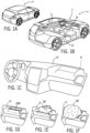
- a vehicle V including an interior I with an instrument panel IP, doors D and a floor console FC.
- interior components of vehicle V such as instrument panel IP and doors D may include trim panels comprised of fiber and plastic.
- instrument panel IP and doors D may provide visible surfaces in the vehicle interior of vehicle V.
- instrument panel IP and/or doors D may provide at least one airbag behind the visible surfaces; instrument panel IP and/or doors D may provide a weakened area to aid the airbag in breaking through the trim panel during airbag deployment. See FIGURES 1D to 1F .
- instrument panel IP may provide a weakened shape/zone shown as a recess R (e.g. a line, score line, cut, notch, groove, discontinuity, interruption, etc.) to facilitate an airbag AB deployment through an airbag door ABD.
- the weakened shape/zone may comprise at least one of a recess or a score line behind the visible surface of instrument panel IP; as shown schematically, the weakened shape/zone may comprise an "H" shape pattern (e.g. corresponding to a door, double-door, etc. for the airbag to comprise the airbag door in the panel). See FIGURES 1C and 1D-1F .
- the weakened shape/zone may comprise a "U" shape pattern, a "bow tie” shape pattern, or any pattern suitable for airbag deployment.
- a trim component 1000 may be provided for a vehicle interior; the component 1000 (e.g. a composite structure) may be configured to support an airbag chute and an airbag module providing an airbag configured to be deployed through an opening into the vehicle interior.
- the component 1000 e.g. composite structure/panel, etc.
- the component 1000 may comprise a structural substrate 210 providing at least one door established upon deployment of the airbag to facilitate deployment of the airbag from the airbag module through the opening.
- Structural substrate 210 may comprise a reinforcement T (shown as comprising a thread pattern, set/network of threads, etc.) configured to secure the at least one door to structural substrate 210 during deployment of the airbag. See e.g. FIGURE 1C-1F , 2B and 8A-8E .
- Reinforcement T may comprise a stitch arrangement (e.g. at least one stitch, set of stitches, pattern of stitches, etc.).
- the reinforcement T may comprise a top stitch TS and a bottom stitch BS (e.g.
- top stitch TS may comprise a thread weight and bottom stitch BS may comprise a thread weight; the thread weight of top stitch TS may be generally greater than the thread weight of bottom stitch BS; for example, top stitch TS may comprise 210 Tex thread; bottom stitch BS may comprise 70 Tex thread.
- bottom stitch BS may be configured to separate upon deployment of the airbag to facilitate deployment of the airbag from the airbag module through the opening; top stitch TS may be configured to secure the door to structural substrate 210 upon deployment of the airbag.
- Top stitch TS may be configured to stretch upon deployment of the airbag to secure the door to structural substrate 210.
- Reinforcement T may be comprised of bonded nylon thread and/or thread material of at least one of (a) KEVLAR, (b) aramid, (c) nylon, (d) polyester, (e) thread, (f) ceramic fibers, (g) polymeric fibers, (h) synthetic fibers.
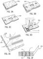
- the structural substrate 210 of the component may comprise a panel comprised at least partially of fibers; reinforcement T may be comprised of thread sewn to the panel (see FIGURES 3D-3F ).
- the thread/reinforcement T e.g. set of stitches, pattern/network of stitches, etc.
- FIGURES 4A-4C See also FIGURES 4A-4C .
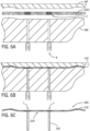
- the panel may comprise a depression 210d; the thread/thread pattern (e.g. reinforcement) may be joined to the panel at depression 210d; the thread/pattern and the panel may form a generally continuous surface 1000s for trim component 1000.
- the thread/thread pattern e.g. reinforcement
- the structural substrate 210 may comprise a compression-formed component for the component/trim component (e.g. composite structure).
- the compression-formed component may comprise a recess 210r in a back side 210b of structural substrate 210 configured to establish the opening so that the airbag will deploy through the compression-formed component at the opening. See e.g. FIGURES 1C- 1F and 7A-7C .
- the structural substrate 210 for the component may be formed at least partially from fibers (e.g. provided as a fiber mat, fiber panel, fiber web, etc.). As indicated schematically, the structural substrate 210 for the composite structure comprises a generally rigid fiber mat. See FIGURES 3A-3F , 4A-4D , 6A-6C and 7A-7C .
- trim component 1000 may further comprise a cover C to provide a surface on a front side 210f of structural substrate 210; the cover C may comprise at least one of (a) leather; (b) synthetic leather; (c) imitation leather; (d) a composite of a plastic layer and textile backing; (e) a coated fabric; (f) polyvinylchloride coated fabric; (g) a woven fabric; (h) a non-woven fabric; (i) an applique; (j) vinyl; (k) a foil.
- the airbag chute may be configured to define/provide at least one hinge area H for the at least one door; reinforcement T may be positioned adjacent the hinge area. See e.g. FIGURES 5A-5C .
- a vehicle interior component 1000 may be produced in a mold M comprising a first surface and a second surface by a process comprising: placing a pre-form substrate 210/210r onto the first surface of the mold, forming a compression-formed structure/structural substrate 210 from pre-form substrate 210/210r by compressing pre-form substrate 210/210r between the first surface of the mold and the second surface of the mold, and applying a cover C to the compression-formed structure 210 to form a panel assembly 210/C providing a surface effect.
- the pre-form substrate 210/210r for the composite structure for the component may comprise a reinforced pre-form substrate (e.g. with reinforcement by thread/stitch pattern, webs, strands, links, etc.); reinforcement T may comprise threads/material such as at least one of (a) KEVLAR, (b) aramid, (c) nylon, (d) polyester, (e) thread, (f) ceramic fibers, (h) polymeric fibers, (i) synthetic fibers.
- the pre-form substrate may comprise a panel comprised at least partially of fibers; reinforcement T may be comprised of thread sewn to the panel. See e.g. FIGURES 3A-3F .
- the compression-formed structure may comprise a substrate layer and reinforcement T. See e.g. FIGURES 4A-4D .
- the substrate layer for the pre-form substrate may comprise a fiber mat; the substrate layer may comprise a generally rigid fiber mat; the step of forming the compression-formed structure may comprise forming the substrate layer into a generally rigid form; the surface effect of the panel assembly may comprise the generally rigid form of the substrate layer of the compression-formed structure. See e.g. FIGURES 3A-3F and 4A-4D .
- the surface effect of the panel assembly may comprise a generally smooth texture and a generally rigid form; the generally smooth texture of the panel assembly may be provided by (a) a surface effect of cover C and (b) a surface effect of the pre-form substrate. See also FIGURES 1C-1F .
- cover C of the panel assembly may comprise at least one of (a) leather; (b) synthetic leather; (c) imitation leather; (d) a composite of a plastic layer and textile backing; (e) a coated fabric; (f) polyvinylchloride coated fabric; (g) a woven fabric; (h) a non-woven fabric; (i) an applique; (j) vinyl; (k) a foil.
- the compression-formed structure may comprise a shape; the panel assembly may comprise at least partially the shape of the compression-formed structure; the shape may comprise a first contour provided by the first surface of the mold and a second contour provided by the second surface of the mold. See e.g.
- the substrate layer for the pre-form substrate may comprise a fiber mat; the process may comprise the step of forming the pre-form substrate from a generally compressible fiber mat. See e.g. FIGURES 3A-3F , 4A-4D , 6A-6C and 7A-7F .
- the pre-form substrate may comprise natural fibers and a resin; the resin may comprise polypropylene; the natural fibers may comprise at least one of (a) flax; (b) kenaf.
- the pre-form substrate may comprise an area weight of between 1000 grams per square meter and 1800 grams per square meter; the pre-form substrate may comprise a thickness of between 1.5 mm and 4 mm; the compression-formed structure may comprise a thickness of between 0.8 mm and 3 mm.
- the process may comprise the step of heating the pre-formed substrate; the pre-formed substrate may be compressed as the pre-formed substrate cools; the process may comprise the step of injecting resin into the mold after the compression-formed structure is formed to form an ancillary component of the panel assembly. See e.g. FIGURES 11A-11B and 12A-12B .
- a component for a vehicle interior configured to support an airbag module configured to deploy an airbag through an airbag chute by establishing a door providing an opening into the vehicle interior for the airbag may comprise a composite structure comprising a structural substrate 210 formed from a fiber panel and a cover C for structural substrate 210 providing an exterior surface.
- Structural substrate 210 comprises a stitch pattern.
- the composite structure is configured so that when the airbag is deployed from the airbag module the stitch pattern provides a reinforcement T for the door providing the opening so that the airbag can be deployed through the opening while the door remains at least partially attached to the composite structure.
- the reinforcement T may comprise a set of threads (e.g.
- the stitch pattern may provide reinforcement T at a hinge area H for the door;
- the stitch pattern may comprise a set of threads (e.g. pattern/network).
- the set of threads for the stitch pattern may comprise a first set of threads and a second set of threads;
- the set of threads for the stitch pattern may comprise an upper set of threads and a lower set of threads;
- the upper set of threads may comprise a set of retaining threads and the lower set of threads may comprise a set of sacrificial threads. See e.g. FIGURES 2B , 3D-3F , 5A-5C and 8A-8E / 9A-9C .
- the set of threads for the stitch pattern may comprise a set of retaining threads configured to stretch and a set of sacrificial threads configured to break; the door may remain at least partially attached to the composite structure by the set of retaining threads; the retaining threads may provide reinforcement T for the door; the sacrificial threads may be configured to rupture when the airbag establishes the door and the opening in the composite structure. See e.g. FIGURES 2B , 3D-3F , 5A-5C and 8A-8E / 9A-9C .
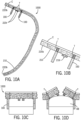
- the set of threads for the stitch pattern may comprise a set of upper threads and a set of lower threads; the upper threads may provide a hinge for the door; the lower threads may comprise sacrificial threads configured to rupture when the airbag establishes the opening in the composite structure. See e.g. FIGURES 8A-8E .
- the stitch pattern may be provided on the fiber panel; the stitch pattern may be formed into structural substrate 210; the stitch pattern may be formed into structural substrate 210 so that the stitch pattern may not be visible at the exterior surface of cover C; the stitch pattern may comprise a network of threads in the fiber panel formed into structural substrate 210.
- the reinforcement T provided by the stitch pattern may comprise reinforcement for the composite structure; the stitch pattern may comprise a first set of threads comprising a first thread weight and second set of threads comprising a second thread weight; the first thread weight may be larger than the second thread weight.
- the stitch pattern may comprise a set of retaining threads comprising 210 Tex thread and a set of sacrificial threads comprising 70 Tex thread.
- the set of retaining threads may be configured to stretch upon deployment of the airbag through the door for the composite structure;
- the stitch pattern may comprise a set of threads at least partially sewn into the fiber panel of structural substrate 210; the set of threads of the stitch pattern may be pressed into a surface of the fiber panel; the set of threads of the stitch pattern may be pressed into a surface of the fiber panel so that structural substrate 210 may comprise a generally flat surface for cover C; the set of threads of the stitch pattern may be pressed into a surface of the fiber panel so that the set of threads may not be visible at the exterior surface of cover C of the composite surface. See e.g. FIGURES 3A-3F , 4A-4D and 7A-7F .
- reinforcement T may comprise bonded nylon thread; the set of threads for the stitch pattern comprising at least one of (a) KEVLAR, (b) aramid, (c) nylon, (d) polyester, (e) thread, (f) ceramic fibers, (h) polymeric fibers, (i) synthetic fibers.
- the component may further comprise a notch (e.g. recess, interruption, line, score line, etc.) in structural substrate 210 configured to facilitate establishment of the opening for the airbag through the composite structure.
- the structural substrate 210 for the component e.g. composite structure
- the component may be formed into a shape; the component may further comprise a feature on structural substrate 210.
- the feature may comprise the airbag chute and/or a resin-formed feature molded 220 on structural substrate 210. See also FIGURES 6A-6C and 7A-7F .
- the feature may comprise at least one of (a) the airbag chute; (b) a passage for the airbag; (c) a rib; (d) a set of ribs; (e) a feature adjacent to reinforcement T; (f) a feature at reinforcement T; (g) a feature at a hinge area; (h) a feature at the opening; (i) a feature configured to facilitate the opening; (j) a structure for the door; (k) a set of ribs configured to establish a seam for the door; (l) structure for a double door comprising the door; (m) the airbag chute at the hinge area; (n) a resin-formed feature.
- the door ABD may comprise a double door; the feature may comprise a seam to facilitate formation of the double door; the door may comprise a double door providing the opening for the airbag; reinforcement T may comprise a hinge area for each door of the double door. See e.g. FIGURES 1C-1F , 8A-8E and 9A-9C .
- the composite structure further may comprise a foam layer F beneath cover C; reinforcement T may comprise a hinge area configured for the door established by deployment of the airbag through the airbag chute; structural substrate 210 may comprise a compression-formed component from the fiber panel; structural substrate 210 may comprise a generally rigid fiber mat.
- cover C may comprise at least one of (a) leather; (b) synthetic leather; (c) imitation leather; (d) a composite of a plastic layer and textile backing; (e) a coated fabric; (f) polyvinylchloride coated fabric; (g) a woven fabric; (h) a non-woven fabric; (i) an applique; (j) vinyl; (k) a foil; (l) coating on structural substrate 210; (m) paint on structural substrate 210; (n) the exterior surface of structural substrate 210.
- the component comprises at least one of an instrument panel; a door panel; a trim panel; a trim component. See e.g. FIGURES 1A-1F .
- a component for a vehicle interior configured to support an airbag module configured to deploy an airbag through an airbag chute by establishing a door providing an opening into the vehicle interior for the airbag may comprise a composite structure comprising a structural substrate 210 formed from a fiber panel, a cover C for structural substrate 210 providing an exterior surface and a feature formed from resin on structural substrate 210.
- Structural substrate 210 may comprise a reinforcement T; reinforcement T may be configured so that the door established by deployment of the airbag remains at least partially attached to the composite structure.
- reinforcement T may comprise a pattern of threads; the pattern of threads may be configured so that when the airbag is deployed from the airbag module the door remains at least partially attached to the composite structure by at least a portion of the pattern of threads; the pattern of threads may comprise a first stitch pattern and a second stitch pattern; the pattern of threads may comprise a set of stitches; the pattern of threads may comprise a stitch network; the stitch network may comprise a hinge for the door; the stitch network for reinforcement T may comprise a set of retaining threads and a set of sacrificial threads; the pattern of threads for reinforcement T may comprise a first set of threads and a second set of threads; the pattern of threads for reinforcement T may comprise a set of retaining threads and a set of sacrificial threads; the pattern of threads for reinforcement T may comprise a set of
- the reinforcement T may comprise a hinge area for the door; reinforcement T may comprise a hinge for the door. See e.g. FIGURES 8A-8E , 9A-9C and 10A-10D .
- the feature may comprise a resin-formed feature molded on structural substrate 210; the feature may comprise the airbag chute (shown as feature 100 and/or 220r); the resin-formed feature may comprise at least one of (a) the airbag chute; (b) a passage for the airbag; (c) a rib; (d) a set of ribs; (e) a feature adjacent to reinforcement T; (f) a feature at reinforcement T; (g) a feature at a hinge area; (h) a feature at the opening; (i) a feature configured to facilitate the opening; (j) structure for the door; (k) a set of ribs configured to establish a seam for the door; (l) structure for a double door comprising the door.
- the reinforcement for the structural substrate/fiber panel of the composite structure/component may be provided with a thread pattern/arrangement T (such as comprising top threads and bottom threads shown as reinforcement/thread pattern).
- a thread pattern/arrangement T such as comprising top threads and bottom threads shown as reinforcement/thread pattern.
- FIGURES 8A-8E pattern with reinforcement T with top threads TS and bottom threads BS
- FIGURE 9A-9C pattern for composite structure with foam layer and reinforcement/thread pattern T).
- the fiber panel 202 e.g. formed mat/panel/pad, lofted mat/panel/pad, uncompressed mat/pad, woven mat/pad, non-woven mat, pre-formed mat, compressed mat, etc.
- the reinforcement/thread pattern T for the composite structure/component facilitates deployment of the airbag AB into the vehicle interior; top threads TS stretch and retain connection (e.g.
- the reinforcement/thread pattern may comprise threads in an arrangement with a variation in pattern/stitch or material or thickness/size or etc. (e.g. variations in strength, variations in Tex value (that may range between and beyond 70 Tex and 210 Tex), variations in density, variations in performance/properties, etc.); for example, the reinforcement/thread pattern may be configured with a top stitch that may tear/separate and a bottom stitch that may stretch/retain (e.g.
- FIGURES 1C-1F , 8D-8E and 9A-9C See e.g. FIGURES 1C-1F , 8D-8E and 9A-9C .
- a trim component for a vehicle interior configured to support an airbag module providing an airbag for deployment through an opening into the vehicle interior may be prepared using a mold by a process comprising the steps of: providing a pre-form substrate, joining a reinforcement T to the pre-form substrate in at least one hinge area to form a reinforced pre-form substrate, disposing the reinforced pre-form substrate onto a first surface of the mold, and compressing the reinforced pre-form substrate between the first surface and a second surface of the mold to form the reinforced pre-form substrate into a structural substrate 210 having a shape.
- the shape for the composite structure/trim component 1000 may correspond to a first contour of the first surface and a second contour of the second surface; structural substrate 210 for the composite structure may be configured to provide at least one door established upon deployment of the airbag to facilitate deployment of the airbag from the airbag module through the opening; reinforcement T for the composite structure may be configured to secure the at least one door to structural substrate 210 during deployment of the airbag. See FIGURES 1C-1F , 2C , 4A-4C and 6A-6C .
- the step of joining a reinforcement T to the pre-form substrate may comprise sewing at least one of a thread; a stitch to the pre-form substrate; the at least one of the thread or the stitch may be comprised of at least one of (a) KEVLAR, (b) aramid, (c) nylon, (d) polyester, (e) ceramic fibers, (f) polymeric fibers, (g) synthetic fibers.
- the step of joining a reinforcement T to the pre-form substrate may comprise piercing an opening in the pre-form substrate and joining a top stitch TS to a bottom stitch BS at the opening; top stitch TS may comprise a thread weight and bottom stitch BS may comprise a thread weight; the thread weight of top stitch TS may be generally greater than the thread weight of bottom stitch BS.
- the process may comprise the step of forming a recess in a surface of at least one of the pre-form substrate; structural substrate 210; the recess may be configured to facilitate deployment of the airbag.
- a method of producing/manufacturing a vehicle trim component configured to support an airbag module providing an airbag for deployment from the airbag module through an opening into the vehicle interior may comprise the steps of: providing a pre-form substrate, joining a reinforcement T to the pre-form substrate in at least one hinge area to form a reinforced pre-form substrate, disposing the reinforced pre-form substrate onto a first surface of the mold, and compressing the reinforced pre-form substrate between the first surface and a second surface of the mold to form the reinforced pre-form substrate into a structural substrate 210 having a shape.
- Structural substrate 210 may be configured to provide at least one door established upon deployment of the airbag to facilitate deployment of the airbag from the airbag module through the opening.
- Reinforcement T may be configured to secure the door to structural substrate 210 during deployment of the airbag.
- a method of manufacturing a vehicle trim component 1000 may comprise the steps of providing a substrate layer (e.g. fiber mat, etc.) as a base for a pre-form substrate, forming the pre-form substrate (e.g. consolidating, compressing, merging/fusing, heating/melting, shaping, cutting/sizing, etc.), joining a reinforcement to the pre-form substrate, pretreating/heating the reinforced pre-form substrate, forming a structural substrate (e.g. compressing/molding the reinforced pre-form substrate), applying a cover to the structural substrate and finishing/providing a panel assembly (with the cover on the structure/substrate).
- a substrate layer e.g. fiber mat, etc.
- the pre-form substrate e.g. consolidating, compressing, merging/fusing, heating/melting, shaping, cutting/sizing, etc.
- joining a reinforcement to the pre-form substrate
- pretreating/heating the reinforced pre-form substrate forming a structural substrate (e.g. compress
- a method of manufacturing a vehicle trim component 1000 may comprise the steps of providing a substrate layer (e.g. fiber mat, etc.) as a base for a pre-form substrate, forming the pre-form substrate (e.g. consolidating, compressing, merging/fusing, heating/melting, shaping, cutting/sizing, etc.), joining a reinforcement to the pre-form substrate, pretreating/heating the reinforced pre-form substrate, forming a structural substrate (e.g. compressing/molding the reinforced pre-form substrate), joining/forming an airbag chute to/on the structural substrate, applying a cover to the structural substrate and finishing/providing a panel assembly (with the cover on the structure/substrate).
- a substrate layer e.g. fiber mat, etc.
- forming the pre-form substrate e.g. consolidating, compressing, merging/fusing, heating/melting, shaping, cutting/sizing, etc.
- joining a reinforcement to the pre-form substrate
- a method of manufacturing a vehicle trim component 1000 may comprise the steps of providing a pre-form substrate, piercing an opening in the pre-form substrate and joining a top stitch to a bottom stitch at the opening, pre-treating/heating the pre-form substrate with the top and the bottom stitch, compressing/molding/forming the pre-form substrate and pressing the top stitch and the bottom stitch into the pre-form substrate to form a structural substrate, applying a cover to the structural substrate, and finishing/providing a panel assembly (with the cover on the structure/substrate).
- a fiber mat 202u may comprise a combination of fibers (e.g. natural and/or synthetic fibers) and thermoplastic resin (e.g. polypropylene (PP), acrylonitrile butadiene styrene (ABS), polycarbonate (PC), etc.).
- thermoplastic resin e.g. polypropylene (PP), acrylonitrile butadiene styrene (ABS), polycarbonate (PC), etc.
- PP polypropylene
- ABS acrylonitrile butadiene styrene
- PC polycarbonate
- fiber mat 202u may be trimmed into a fiber mat 202t having a thickness.
- fiber mat 202t may be heated to induce the thermoplastic resin to liquefy.
- heated fiber mat 202t may be partially compressed into a fiber panel 202 having a thickness less than the thickness of fiber mat 202t.
- a reinforcement T comprising at least one of (a) KEVLAR, (b) aramid, (c) nylon, (d) polyester, (e) thread, (f) ceramic fibers, (g) polymeric fibers, (h) synthetic fibers, (i) a stitch may be sewn to fiber panel 202 to form reinforced fiber panel 202r.
- reinforced fiber panel 202r may be heated in an oven OV.
- heated reinforced fiber panel 202r may be transferred into a mold having a mold top MT and mold bottom MB.
- a component shown as an instrument panel substrate 200 may be produced by a process of compression forming heated reinforced fiber panel 202r into a structural substrate 210 and injection molding resin onto compression formed heated reinforced fiber panel 202r.
- a recess 210r of structural substrate 210 may be formed in the process.
- Recess 210r may define a door to be established upon deployment of an airbag to facilitate deployment of the airbag from an airbag module through an opening.
- Reinforcement T may be configured to secure the door to structural substrate 210 during deployment of the airbag.
- instrument panel substrate 200 may provide a feature shown as a plastic rib 220 on a back side of structural substrate 210 to improve structural integrity and rigidity of structural substrate 210.
- Structural substrate 210 may be configured to support an airbag chute 100 and an airbag module comprising an airbag.
- plastic rib 220 may comprise a reinforcement 220r to provide structural support; plastic rib 220 may comprise a border 220b to provide reinforcement and/or dimensional accuracy for structural substrate 210.
- plastic rib 220 may be placed at any location on structural substrate 210 (e.g.
- plastic ribs 220 may be placed at various different locations on structural substrate 210.
- plastic rib 220 may improve structural integrity of instrument panel substrate 200.
- instrument panel substrate 200 may be able to maintain structural integrity during an airbag deployment; the position/placement of plastic rib 220 may be intended to create a strength differential between different areas of instrument panel substrate 200; energy needed for an airbag to break through a vehicle interior component 1000 may be directed to recess 210r of structural substrate 210; plastic rib 220 may prevent or minimize ripping or tearing of structural substrate 210 at any location other than at recess 210r during an airbag deployment.
- plastic rib 220 may form a honeycomb shaped pattern to improve structural integrity and rigidity.
- plastic rib 220 may be formed in any configuration according to a specific application (e.g. ancillary features for attaching air vents, speakers or infotainment system, etc.).
- a trim component 1000 for a vehicle interior may be configured to support an airbag chute and an airbag module providing an airbag AB configured to be deployed through an opening into the vehicle interior.
- Trim component 1000 may comprise a structural substrate 200 providing a front side, a back side and at least one door established upon deployment of airbag AB to facilitate deployment of airbag AB from the airbag module through the opening.
- Structural substrate 200 may comprise a reinforcement T configured to secure the door to structural substrate 200 during deployment of airbag AB.
- Reinforcement T may comprise at least one stitch.
- Reinforcement T may be comprised of at least one of (a) KEVLAR, (b) aramid, (c) nylon, (d) polyester, (e) thread, (f) ceramic fibers, (g) polymeric fibers, (h) synthetic fibers.
- Structural substrate 200 may comprise a panel 202 comprised at least partially of fibers. Reinforcement T may be comprised of thread sewn to panel 202.
- Structural substrate 200 may comprise a compression-formed component 210.
- Compression-formed component 210 may comprise a recess 210r in the back side of structural substrate 200 configured to establish the opening so that airbag AB will deploy through compression-formed component 210 at the opening.
- Structural substrate 200 may be formed at least partially from fibers.
- Trim component 1000 may comprise a cover C to provide a surface on the front side of structural substrate 200. Contact between airbag AB and the door may induce tearing of cover C to establish the opening for the airbag and may facilitate deployment of airbag AB through the
- a trim component 1000 for a vehicle interior configured to support an airbag module providing an airbag AB for deployment through an opening into the vehicle interior may be prepared using a mold M by a process.
- the process may comprise the steps of providing a fiber panel 202, joining a reinforcement T to fiber panel 202 in at least one hinge area to form a reinforced fiber panel 202r, disposing reinforced fiber panel 202r onto a first surface of mold M, compressing reinforced fiber panel 202r between the first surface and a second surface of mold M to form reinforced fiber panel 202r into a structural substrate 200 having a shape and attaching a structure 100 on a side of structural substrate 200.
- Structural substrate 200 may be configured to provide at least one door established upon deployment of airbag AB to facilitate deployment of airbag AB from the airbag module through the opening.
- Structure 100 may be configured to support the airbag module and to direct airbag AB toward structural substrate 200 to establish the opening and the door during deployment of airbag AB.
- Reinforcement T may be configured to secure the door to structural substrate 200 during deployment of airbag AB.
- Joining reinforcement T to fiber panel 202 may comprise sewing at least one of a thread; a stitch to fiber panel 202.
- the at least one of the thread; the stitch may be comprised of at least one of (a) KEVLAR, (b) aramid, (c) nylon, (d) polyester, (e) ceramic fibers, (f) polymeric fibers, (g) synthetic fibers.
- Attaching structure 100 on a side of structural substrate 200 may comprise injecting resin into mold M.
- the process may comprise the step of forming a recess 210r in a surface of at least one of fiber panel 202; reinforced fiber panel 202r; recess 210r may be configured to facilitate deployment of airbag AB.
- Structural substrate 200 may be configured to provide at least one door established upon deployment of the airbag to facilitate deployment of the airbag from the airbag module through the opening.
- Structure 100 may be configured to support the airbag module and may direct airbag AB toward structural substrate 200 to establish the opening and the door during deployment of airbag AB.
- Reinforcement T may be configured to secure the door to structural substrate 200 during deployment of the airbag.
Landscapes
- Engineering & Computer Science (AREA)
- Mechanical Engineering (AREA)
- Manufacturing & Machinery (AREA)
- Air Bags (AREA)
Description
- The present invention relates to a vehicle component.
- It is known to provide an airbag in a vehicle configured to deploy through an airbag chute on a trim component and into a vehicle interior.
- It would be advantageous to provide an improved trim component configured to provide a reinforcement such as a thread/thread pattern at or adjacent the airbag chute on the trim component. Document
US 9 090 222 B2 - The present invention relates to a component for a vehicle interior as defined by
claim 1. The reinforcement may comprise a top stitch and a bottom stitch. The top stitch may comprise a thread weight and the bottom stitch may comprise a thread weight; the thread weight of the top stitch may be generally greater than the thread weight of the bottom stitch. The top stitch may comprise 210 Tex thread; the bottom stitch may comprise 70 Tex thread. The bottom stitch may be configured to separate upon deployment of the airbag to facilitate deployment of the airbag from the airbag module through the opening. The top stitch may be configured to secure the door to the structural substrate upon deployment of the airbag. The top stitch may be configured to stretch upon deployment of the airbag to secure the door to the structural substrate. The reinforcement may be comprised of bonded nylon thread. The reinforcement may be comprised of at least one of (a) KEVLAR, (b) aramid, (c) nylon, (d) polyester, (e) thread, (f) ceramic fibers, (h) polymeric fibers, (i) synthetic fibers. The structural substrate may comprise a panel comprised at least partially of fibers; the reinforcement may be comprised of thread sewn to the panel. The thread may be pressed into a surface of the panel during a compression forming process. The panel may comprise a depression; the thread may be joined to the panel at the depression. The thread and the panel may form a generally continuous surface for the trim component. The structural substrate may comprise a compression-formed component. The compression-formed component may comprise a recess in a back side of the structural substrate configured to establish the opening so that the airbag will deploy through the compression-formed component at the opening. The structural substrate may be formed at least partially from fibers. The trim component may further comprise a cover to provide a surface on a front side of the structural substrate. Contact between the airbag and the at least one door may induce tearing of the cover to establish the opening for the airbag and to facilitate deployment of the airbag through the opening. The airbag chute may define at least one hinge area for the at least one door; the reinforcement may be positioned adjacent the hinge area. The structural substrate comprises a generally rigid fiber mat. The trim component may further comprise a cover; the cover may comprise at least one of (a) leather; (b) synthetic leather; (c) imitation leather; (d) a composite of a plastic layer and textile backing; (e) a coated fabric; (f) polyvinylchloride coated fabric; (g) a woven fabric; (h) a non-woven fabric; (i) an applique; (j) vinyl; (k) a foil. - An aspect which is not part of the present invention relates to a vehicle interior component produced in a mold comprising a first surface and a second surface by a process comprising: placing a pre-form substrate onto the first surface of the mold, forming a compression-formed structure from the pre-form substrate by compressing the pre-form substrate between the first surface of the mold and the second surface of the mold, and applying a cover to the compression-formed structure to form a panel assembly providing a surface effect. The pre-form substrate may comprise a reinforced pre-form substrate. The reinforcement may comprise at least one of (a) KEVLAR, (b) aramid, (c) nylon, (d) polyester, (e) thread, (f) ceramic fibers, (h) polymeric fibers, (i) synthetic fibers. The substrate layer may comprise a panel comprised at least partially of fibers; the reinforcement may be comprised of thread sewn to the panel. The compression-formed structure may comprise the substrate layer and the reinforcement. The reinforced pre-form substrate may comprise a surface effect comprising a generally smooth texture. The surface effect of the panel assembly may generally comprise the surface effect of the reinforced pre-from substrate. The step of forming the compression-formed structure may comprise forming the reinforcement and the pre-form substrate into a generally continuous surface. The substrate layer for the pre-form substrate may comprise a fiber mat. The substrate layer may comprise a generally rigid fiber mat. The step of forming the compression-formed structure may comprise forming the substrate layer into a generally rigid form. The surface effect of the panel assembly may comprise the generally rigid form of the substrate layer of the compression-formed structure. The surface effect of the panel assembly may comprise a generally smooth texture and a generally rigid form. The generally smooth texture of the panel assembly may be provided by (a) a surface effect of the cover and (b) a surface effect of the pre-form substrate. The cover of the panel assembly may comprise at least one of (a) leather; (b) synthetic leather; (c) imitation leather; (d) a composite of a plastic layer and textile backing; (e) a coated fabric; (f) polyvinylchloride coated fabric; (g) a woven fabric; (h) a non-woven fabric; (i) an applique; (j) vinyl; (k) a foil. The compression-formed structure may comprise a shape. The panel assembly may comprise at least partially the shape of the compression-formed structure. The shape may comprise a first contour provided by the first surface of the mold and a second contour provided by the second surface of the mold. The substrate layer for the pre-form substrate may comprise a fiber mat. The process may comprise the step of forming the pre-form substrate from a generally compressible fiber mat. The pre-form substrate may comprise natural fibers and a resin. The resin may comprise polypropylene and the natural fibers comprise at least one of (a) flax; (b) kenaf. The pre-form substrate may comprise an area weight of between 1000 grams per square meter and 1800 grams per square meter. The pre-form substrate may comprise a thickness of between 1.5 mm and 4 mm; the compression-formed structure may comprise a thickness of between 0.8 mm and 3 mm. The process may comprise the step of heating the pre-formed substrate; the pre-formed substrate may be compressed as the pre-formed substrate cools. The process may comprise the step of injecting resin into the mold after the compression-formed structure is formed to form an ancillary component of the panel assembly.
- The present invention relates to a component for a vehicle interior configured to support an airbag module configured to deploy an airbag through an airbag chute by establishing a door providing an opening into the vehicle interior for the airbag comprising a composite structure comprising a structural substrate formed from a fiber panel and a cover for the structural substrate providing an exterior surface. The structural substrate comprises a stitch pattern. The composite structure may be configured so that when the airbag is deployed from the airbag module the stitch pattern provides a reinforcement for the door providing the opening so that the airbag can be deployed through the opening while the door remains at least partially attached to the composite structure. The reinforcement may comprise a set of threads. The stitch pattern may provide the reinforcement at a hinge area for the door. The stitch pattern may comprise a set of threads. The set of threads for the stitch pattern may comprise a first set of threads and a second set of threads. The set of threads for the stitch pattern may comprise an upper set of threads and a lower set of threads. The upper set of threads may comprise a set of retaining threads and the lower set of threads may comprise a set of sacrificial threads. The set of threads for the stitch pattern may comprise a set of retaining threads configured to stretch and a set of sacrificial threads configured to break. The door may remain at least partially attached to the composite structure by the set of retaining threads. The retaining threads may provide the reinforcement for the door. The sacrificial threads may be configured to rupture when the airbag establishes the door and the opening in the composite structure. The set of threads for the stitch pattern may comprise a set of upper threads and a set of lower threads; the upper threads may provide a hinge for the door; the lower threads may comprise sacrificial threads configured to rupture when the airbag establishes the opening in the composite structure. The stitch pattern may be provided on the fiber panel. The stitch pattern may be formed into the structural substrate. The stitch pattern may be formed into the structural substrate so that the stitch pattern may not be visible at the exterior surface of the cover. The stitch pattern may comprise a network of threads in the fiber panel formed into the structural substrate. The reinforcement provided by the stitch pattern may comprise reinforcement for the composite structure. The stitch pattern may comprise a first set of threads comprising a first thread weight and second set of threads comprising a second thread weight; the first thread weight may be larger than the second thread weight. The stitch pattern may comprise a set of retaining threads comprising 210 Tex thread and a set of sacrificial threads comprising 70 Tex thread. The set of retaining threads may be configured to stretch upon deployment of the airbag through the door for the composite structure. The stitch pattern may comprise a set of threads at least partially sewn into the fiber panel of the structural substrate. The set of threads of the stitch pattern may be pressed into a surface of the fiber panel. The set of threads of the stitch pattern may be pressed into a surface of the fiber panel so that the structural substrate may comprise a generally flat surface for the cover. The set of threads of the stitch pattern may be pressed into a surface of the fiber panel so that the set of threads may not be visible at the exterior surface of the cover of the composite surface. The reinforcement may comprise bonded nylon thread. The reinforcement may comprise a set of threads for the stitch pattern comprising at least one of (a) KEVLAR, (b) aramid, (c) nylon, (d) polyester, (e) thread, (f) ceramic fibers, (h) polymeric fibers, (i) synthetic fibers. The component may further comprise a notch in the structural substrate configured to facilitate establishment of the opening for the airbag through the composite structure. The structural substrate may be formed into a shape. The component may further comprise a feature on the structural substrate. The feature may comprise the airbag chute. The feature may comprise a resin-formed feature molded on the structural substrate. The feature may comprise at least one of (a) the airbag chute; (b) a passage for the airbag; (c) a rib; (d) a set of ribs; (e) a feature adjacent to the reinforcement; (f) a feature at the reinforcement; (g) a feature at a hinge area; (h) a feature at the opening; (i) a feature configured to facilitate the opening; (j) a structure for the door; (k) a set of ribs configured to establish a seam for the door; (l) structure for a double door comprising the door; (m) the airbag chute at the hinge area; (n) a resin-formed feature. The door may comprise a double door; the feature may comprise a seam to facilitate formation of the double door. The door may comprise a double door providing the opening for the airbag; the reinforcement may comprise a hinge area for each door of the double door. The composite structure further may comprise a foam layer beneath the cover. The reinforcement may comprise a hinge area configured for the door established by deployment of the airbag through the airbag chute. The structural substrate may comprise a compression-formed component from the fiber panel. The structural substrate may comprise a generally rigid fiber mat. The cover may comprise at least one of (a) leather; (b) synthetic leather; (c) imitation leather; (d) a composite of a plastic layer and textile backing; (e) a coated fabric; (f) polyvinylchloride coated fabric; (g) a woven fabric; (h) a non-woven fabric; (i) an applique; (j) vinyl; (k) a foil; (1) coating on the structural substrate; (m) paint on the structural substrate; (n) the exterior surface of the structural substrate. The component may comprise at least one of an instrument panel; a door panel; a trim panel; a trim component.
- The present invention relates to a component for a vehicle interior configured to support an airbag module configured to deploy an airbag through an airbag chute by establishing a door providing an opening into the vehicle interior for the airbag comprising a composite structure comprising a structural substrate formed from a fiber panel, a cover for the structural substrate providing an exterior surface and a feature formed from resin on the structural substrate. The structural substrate may comprise a reinforcement; the reinforcement is configured so that the door established by deployment of the airbag remains at least partially attached to the composite structure. The reinforcement may comprise a pattern of threads; the pattern of threads may be configured so that when the airbag is deployed from the airbag module the door remains at least partially attached to the composite structure by at least a portion of the pattern of threads. The pattern of threads may comprise a first stitch pattern and a second stitch pattern. The pattern of threads may comprise a set of stitches. The pattern of threads may comprise a stitch network. The stitch network may comprise a hinge for the door; the stitch network for the reinforcement may comprise a set of retaining threads and a set of sacrificial threads. The pattern of threads for the reinforcement may comprise a first set of threads and a second set of threads. The pattern of threads for the reinforcement may comprise a set of retaining threads and a set of sacrificial threads. The pattern of threads for the reinforcement may comprise a set of strong threads and a set of weak threads. The set of threads for the reinforcement may comprise a set of retaining threads and a set of sacrificial threads; the set of retaining threads may be configured to comprise the reinforcement after deployment of the airbag. The reinforcement may comprise a hinge area for the door. The reinforcement may comprise a hinge for the door. The feature may comprise a resin-formed feature molded on the structural substrate. The feature may comprise the airbag chute. The resin-formed feature may comprise at least one of (a) the airbag chute; (b) a passage for the airbag; (c) a rib; (d) a set of ribs; (e) a feature adjacent to the reinforcement; (f) a feature at the reinforcement; (g) a feature at a hinge area; (h) a feature at the opening; (i) a feature configured to facilitate the opening; (j) structure for the door; (k) a set of ribs configured to establish a seam for the door; (l) structure for a double door comprising the door.
- An aspect which is not part of the present invention relates to a trim component for a vehicle interior configured to support an airbag module providing an airbag for deployment through an opening into the vehicle interior prepared using a mold by a process comprising the steps of: providing a pre-form substrate, joining a reinforcement to the pre-form substrate in at least one hinge area to form a reinforced pre-form substrate, disposing the reinforced pre-form substrate onto a first surface of the mold, and compressing the reinforced pre-form substrate between the first surface and a second surface of the mold to form the reinforced pre-form substrate into a structural substrate having a shape. The shape may correspond to a first contour of the first surface and a second contour of the second surface. The structural substrate may be configured to provide at least one door established upon deployment of the airbag to facilitate deployment of the airbag from the airbag module through the opening. The reinforcement may be configured to secure the at least one door to the structural substrate during deployment of the airbag. The step of joining a reinforcement to the pre-form substrate may comprise sewing at least one of a thread; a stitch to the pre-form substrate. The at least one of the thread or the stitch may be comprised of at least one of (a) KEVLAR, (b) aramid, (c) nylon, (d) polyester, (e) ceramic fibers, (f) polymeric fibers, (g) synthetic fibers. The step of joining a reinforcement to the pre-form substrate may comprise piercing an opening in the pre-form substrate and joining a top stitch to a bottom stitch at the opening. The top stitch may comprise a thread weight and the bottom stitch may comprise a thread weight; the thread weight of the top stitch may be generally greater than the thread weight of the bottom stitch. The process may comprise the step of forming a recess in a surface of at least one of the pre-form substrate; the structural substrate; the recess may be configured to facilitate deployment of the airbag.
- An aspect which is not part of the present invention relates to a method of manufacturing a vehicle trim component configured to support an airbag module providing an airbag for deployment from the airbag module through an opening into the vehicle interior comprising the steps of: providing a pre-form substrate, joining a reinforcement to the pre-form substrate in at least one hinge area to form a reinforced pre-form substrate, disposing the reinforced pre-form substrate onto a first surface of the mold, and compressing the reinforced pre-form substrate between the first surface and a second surface of the mold to form the reinforced pre-form substrate into a structural substrate having a shape. The shape may correspond to a first contour of the first surface and a second contour of the second surface. The structural substrate may be configured to provide at least one door established upon deployment of the airbag to facilitate deployment of the airbag from the airbag module through the opening. The reinforcement may be configured to secure the door to the structural substrate during deployment of the airbag.
- The present invention relates to a trim component for a vehicle interior configured to support an airbag chute and an airbag module providing an airbag configured to be deployed through an opening into the vehicle interior. The component may comprise a structural substrate providing a front side, a back side and at least one door established upon deployment of the airbag to facilitate deployment of the airbag from the airbag module through the opening. The structural substrate may comprise a reinforcement configured to secure the door to the structural substrate during deployment of the airbag. The reinforcement may comprise at least one stitch. The reinforcement may be comprised of at least one of (a) KEVLAR, (b) aramid, (c) nylon, (d) polyester, (e) thread, (f) ceramic fibers, (g) polymeric fibers, (h) synthetic fibers. The structural substrate may comprise a panel comprised at least partially of fibers. The reinforcement may be comprised of thread sewn to the panel. The structural substrate may comprise a compression-formed component. The compression-formed component may comprise a recess in the back side of the structural substrate configured to establish the opening so that the airbag will deploy through the compression-formed component at the opening. The structural substrate may be formed at least partially from fibers. The trim component may comprise a cover to provide a surface on the front side of the structural substrate. Contact between the airbag and the door may induce tearing of the cover to establish the opening for the airbag and may facilitate deployment of the airbag through the opening.
- An aspect which is not part of the present invention relates to a trim component for a vehicle interior configured to support an airbag module providing an airbag for deployment through an opening into the vehicle interior prepared using a mold by a process. The process may comprise the steps of providing a fiber panel, joining a reinforcement to the fiber panel in at least one hinge area to form a reinforced fiber panel, disposing the reinforced fiber panel onto a first surface of the mold, compressing the reinforced fiber panel between the first surface and a second surface of the mold to form the reinforced fiber panel into a structural substrate having a shape and attaching a structure on a side of the structural substrate. The shape may correspond to a first contour of the first surface and a second contour of the second surface. The structural substrate may be configured to provide at least one door established upon deployment of the airbag to facilitate deployment of the airbag from the airbag module through the opening. The structure may be configured to support the airbag module and to direct the airbag toward the structural substrate to establish the opening and the door during deployment of the airbag. The reinforcement may be configured to secure the door to the structural substrate during deployment of the airbag. Joining a reinforcement to the fiber panel may comprise sewing at least one of a thread; a stitch to the fiber panel. The at least one of the thread; the stitch may be comprised of at least one of (a) KEVLAR, (b) aramid, (c) nylon, (d) polyester, (e) ceramic fibers, (f) polymeric fibers, (g) synthetic fibers. Attaching the structure on a side of the structural substrate may comprise injecting resin into the mold. The process may comprise the step of forming a recess in a surface of at least one of the fiber panel; the reinforced fiber panel; the recess may be configured to facilitate deployment of the airbag.
- An aspect which is not part of the present invention relates to a method of manufacturing a vehicle trim component configured to support an airbag module providing an airbag for deployment from the airbag module through an opening into the vehicle interior. The method may comprise the steps of providing a fiber panel, joining a reinforcement to the fiber panel in at least one hinge area to form a reinforced fiber panel, disposing the reinforced fiber panel onto a first surface of the mold, compressing the reinforced fiber panel between the first surface and a second surface of the mold to form the reinforced fiber panel into a structural substrate having a shape and attaching a structure on a side of the structural substrate. The shape may correspond to a first contour of the first surface and a second contour of the second surface. The structural substrate may be configured to provide at least one door established upon deployment of the airbag to facilitate deployment of the airbag from the airbag module through the opening. The structure may be configured to support the airbag module and may direct the airbag toward the structural substrate to establish the opening and the door during deployment of the airbag. The reinforcement may be configured to secure the door to the structural substrate during deployment of the airbag.
-
-
FIGURE 1A is a schematic perspective view of a vehicle according to an exemplary embodiment. -
FIGURE 1B is a schematic perspective cut-away view of a vehicle showing a vehicle interior according to an exemplary embodiment. -
FIGURE 1C is a schematic perspective view of a vehicle trim component shown as an instrument panel according to an exemplary embodiment. -
FIGURES 1D through 1F are schematic perspective detail views of an airbag deployment according to an exemplary embodiment. -
FIGURE 2A is a schematic perspective view of a vehicle trim component shown as an instrument panel according to an exemplary embodiment. -
FIGURE 2B is a schematic exploded perspective view of a vehicle trim component shown as an instrument panel according to an exemplary embodiment. -
FIGURE 2C is a schematic partial section view of a vehicle trim component shown as an instrument panel according to an exemplary embodiment. -
FIGURES 3A through 3F are schematic perspective views of a process to form a reinforced fiber panel according to an exemplary embodiment. -
FIGURES 4A through 4C are schematic perspective views of a process to form a structural substrate from a reinforced fiber panel according to an exemplary embodiment. -
FIGURE 4D is a schematic perspective cut-away view of a structural substrate according to an exemplary embodiment. -
FIGURES 4E through 4F are schematic perspective cut-away views of a trim component for a vehicle interior according to an exemplary embodiment. -
FIGURE 5A is a schematic perspective view of a structural substrate according to an exemplary embodiment. -
FIGURE 5B is a schematic partial perspective view of a structural substrate according to an exemplary embodiment. -
FIGURE 5C is a schematic partial plan view of a reinforcement for a structural substrate according to an exemplary embodiment. -
FIGURES 6A through 6C are schematic partial section views of a process to form a structural substrate with an airbag chute from a reinforced fiber panel according to an exemplary embodiment. -
FIGURES 7A through 7E are schematic partial section views of a process to form a vehicle interior component shown as an instrument panel according to an exemplary embodiment. -
FIGURE 7F is a schematic partial section view of a vehicle trim component shown as an instrument panel according to an exemplary embodiment. -
FIGURE 8A is a schematic partial section view of a vehicle trim component shown as an instrument panel according to an exemplary embodiment. -
FIGURES 8B through 8D are schematic partial section views of an airbag deployment according to an exemplary embodiment. -
FIGURE 8E is a schematic partial perspective view of a vehicle trim component shown as an instrument panel according to an exemplary embodiment. -
FIGURES 9A through 9C are partial schematic section views of a trim component for a vehicle interior according to an exemplary embodiment. -
FIGURE 10A is a schematic section view of a trim component for a vehicle interior according to an exemplary embodiment. -
FIGURE 10B is a schematic cut-away section view of a trim component for a vehicle interior according to an exemplary embodiment. -
FIGURES 10C through 10D are schematic cut-away section views of a deployment of an airbag through a trim component for a vehicle interior according to an exemplary embodiment. -
FIGURE 11A is a schematic flow diagram of a method for forming a vehicle interior component. -
FIGURE 11B is a schematic flow diagram of a method for forming a vehicle interior component according. -
FIGURES 12A and 12B are schematic flow diagrams of a method for forming a vehicle interior component. - Referring to
FIGURES 1A and 1B , a vehicle V is shown including an interior I with an instrument panel IP, doors D and a floor console FC. According to an exemplary embodiment, interior components of vehicle V such as instrument panel IP and doors D may include trim panels comprised of fiber and plastic. According to an exemplary embodiment, instrument panel IP and doors D may provide visible surfaces in the vehicle interior of vehicle V. According to an exemplary embodiment, instrument panel IP and/or doors D may provide at least one airbag behind the visible surfaces; instrument panel IP and/or doors D may provide a weakened area to aid the airbag in breaking through the trim panel during airbag deployment. SeeFIGURES 1D to 1F . - According to an exemplary embodiment as shown schematically in
FIGURES 1C to 1F , instrument panel IP may provide a weakened shape/zone shown as a recess R (e.g. a line, score line, cut, notch, groove, discontinuity, interruption, etc.) to facilitate an airbag AB deployment through an airbag door ABD. According to an exemplary embodiment, the weakened shape/zone may comprise at least one of a recess or a score line behind the visible surface of instrument panel IP; as shown schematically, the weakened shape/zone may comprise an "H" shape pattern (e.g. corresponding to a door, double-door, etc. for the airbag to comprise the airbag door in the panel). SeeFIGURES 1C and1D-1F . According to an exemplary embodiment, the weakened shape/zone may comprise a "U" shape pattern, a "bow tie" shape pattern, or any pattern suitable for airbag deployment. - According to an exemplary embodiment as shown schematically in
FIGURES 2A-2C ,3A-3F ,4A-4F ,5A-5C ,6A-6C ,7A-7F ,8A-8E ,9A-9C ,10A-10D ,11A-11B and12A-12B , atrim component 1000 may be provided for a vehicle interior; the component 1000 (e.g. a composite structure) may be configured to support an airbag chute and an airbag module providing an airbag configured to be deployed through an opening into the vehicle interior. The component 1000 (e.g. composite structure/panel, etc.) may comprise astructural substrate 210 providing at least one door established upon deployment of the airbag to facilitate deployment of the airbag from the airbag module through the opening. SeeFIGURES 1C-1F and2A-2C .Structural substrate 210 may comprise a reinforcement T (shown as comprising a thread pattern, set/network of threads, etc.) configured to secure the at least one door tostructural substrate 210 during deployment of the airbag. See e.g.FIGURE 1C-1F ,2B and8A-8E . Reinforcement T may comprise a stitch arrangement (e.g. at least one stitch, set of stitches, pattern of stitches, etc.). As shown schematically according to an exemplary embodiment inFIGURES 2B-2C ,3D-3F ,4C ,5A-5C and7A-7F , the reinforcement T may comprise a top stitch TS and a bottom stitch BS (e.g. to comprise the pattern of stitches, stitch network, etc.). See alsoFIGURES 8A-8E . According to an exemplary embodiment, top stitch TS may comprise a thread weight and bottom stitch BS may comprise a thread weight; the thread weight of top stitch TS may be generally greater than the thread weight of bottom stitch BS; for example, top stitch TS may comprise 210 Tex thread; bottom stitch BS may comprise 70 Tex thread. As indicated schematically inFIGURES 8A-8E , bottom stitch BS may be configured to separate upon deployment of the airbag to facilitate deployment of the airbag from the airbag module through the opening; top stitch TS may be configured to secure the door tostructural substrate 210 upon deployment of the airbag. Top stitch TS may be configured to stretch upon deployment of the airbag to secure the door tostructural substrate 210. Reinforcement T may be comprised of bonded nylon thread and/or thread material of at least one of (a) KEVLAR, (b) aramid, (c) nylon, (d) polyester, (e) thread, (f) ceramic fibers, (g) polymeric fibers, (h) synthetic fibers. - As shown schematically according to an exemplary embodiment in
FIGURES 2A-2C and3A-3F , thestructural substrate 210 of the component (e.g. composite structure) may comprise a panel comprised at least partially of fibers; reinforcement T may be comprised of thread sewn to the panel (seeFIGURES 3D-3F ). As indicated schematically according to an exemplary embodiment inFIGURES 6A-6C and7A-7C , the thread/reinforcement T (e.g. set of stitches, pattern/network of stitches, etc.) may be pressed into a surface of the panel during a compression forming process. See alsoFIGURES 4A-4C . As shown schematically inFIGURES 7D-7E , the panel may comprise adepression 210d; the thread/thread pattern (e.g. reinforcement) may be joined to the panel atdepression 210d; the thread/pattern and the panel may form a generallycontinuous surface 1000s fortrim component 1000. - As indicated schematically according to an exemplary embodiment in
FIGURES 4A- 4D ,6A-6C and7A-7C , thestructural substrate 210 may comprise a compression-formed component for the component/trim component (e.g. composite structure). As indicated schematically, the compression-formed component may comprise arecess 210r in aback side 210b ofstructural substrate 210 configured to establish the opening so that the airbag will deploy through the compression-formed component at the opening. See e.g.FIGURES 1C- 1F and7A-7C . As shown schematically inFIGURES 3A-3F ,4A-4D ,6A-6C ,7A-7C and8A-8E , thestructural substrate 210 for the component may be formed at least partially from fibers (e.g. provided as a fiber mat, fiber panel, fiber web, etc.). As indicated schematically, thestructural substrate 210 for the composite structure comprises a generally rigid fiber mat. SeeFIGURES 3A-3F ,4A-4D ,6A-6C and7A-7C . - As indicated schematically according to an exemplary embodiment in
FIGURE 1C-1F and7D ,trim component 1000 may further comprise a cover C to provide a surface on afront side 210f ofstructural substrate 210; the cover C may comprise at least one of (a) leather; (b) synthetic leather; (c) imitation leather; (d) a composite of a plastic layer and textile backing; (e) a coated fabric; (f) polyvinylchloride coated fabric; (g) a woven fabric; (h) a non-woven fabric; (i) an applique; (j) vinyl; (k) a foil. - As indicated schematically according to an exemplary embodiment in
FIGURES 8A- 8E , in operation of the airbag with the trim component contact between the airbag and the at least one door may induce tearing of cover C to establish the opening for the airbag and to facilitate deployment of the airbag through the opening in the trim component (e.g. through the composite structure); the airbag chute may be configured to define/provide at least one hinge area H for the at least one door; reinforcement T may be positioned adjacent the hinge area. See e.g.FIGURES 5A-5C . - According to an exemplary embodiment as shown schematically in
FIGURES 2A-2C ,3A-3F ,4A-4F ,5A-5C ,6A-6C ,7A-7F ,8A-8E ,9A-9C ,10A-10D ,11A-11B and12A-12B , avehicle interior component 1000 may be produced in a mold M comprising a first surface and a second surface by a process comprising: placing apre-form substrate 210/210r onto the first surface of the mold, forming a compression-formed structure/structural substrate 210 frompre-form substrate 210/210r by compressingpre-form substrate 210/210r between the first surface of the mold and the second surface of the mold, and applying a cover C to the compression-formedstructure 210 to form apanel assembly 210/C providing a surface effect. As indicated schematically inFIGURES 4A-4C , thepre-form substrate 210/210r for the composite structure for the component may comprise a reinforced pre-form substrate (e.g. with reinforcement by thread/stitch pattern, webs, strands, links, etc.); reinforcement T may comprise threads/material such as at least one of (a) KEVLAR, (b) aramid, (c) nylon, (d) polyester, (e) thread, (f) ceramic fibers, (h) polymeric fibers, (i) synthetic fibers. The pre-form substrate may comprise a panel comprised at least partially of fibers; reinforcement T may be comprised of thread sewn to the panel. See e.g.FIGURES 3A-3F . As shown schematically, the compression-formed structure may comprise a substrate layer and reinforcement T. See e.g.FIGURES 4A-4D . The reinforced pre-form substrate may comprise a surface effect comprising a generally smooth texture; the surface effect of the panel assembly may generally comprise the surface effect of the reinforced pre-from substrate; the step of forming the compression-formed structure may comprise forming reinforcement T and the pre-form substrate into a generallycontinuous surface 210s. See e.g.FIGURES 7A-7C . The substrate layer for the pre-form substrate may comprise a fiber mat; the substrate layer may comprise a generally rigid fiber mat; the step of forming the compression-formed structure may comprise forming the substrate layer into a generally rigid form; the surface effect of the panel assembly may comprise the generally rigid form of the substrate layer of the compression-formed structure. See e.g.FIGURES 3A-3F and4A-4D . As indicated schematically inFIGURES 6A-6C and7A-7F , the surface effect of the panel assembly may comprise a generally smooth texture and a generally rigid form; the generally smooth texture of the panel assembly may be provided by (a) a surface effect of cover C and (b) a surface effect of the pre-form substrate. See alsoFIGURES 1C-1F . According to an exemplary embodiment, cover C of the panel assembly may comprise at least one of (a) leather; (b) synthetic leather; (c) imitation leather; (d) a composite of a plastic layer and textile backing; (e) a coated fabric; (f) polyvinylchloride coated fabric; (g) a woven fabric; (h) a non-woven fabric; (i) an applique; (j) vinyl; (k) a foil. As indicate schematically inFIGURES 1C and4C , the compression-formed structure may comprise a shape; the panel assembly may comprise at least partially the shape of the compression-formed structure; the shape may comprise a first contour provided by the first surface of the mold and a second contour provided by the second surface of the mold. See e.g.FIGURES 4A-4C ,6A-6C and7A-7F . As indicated schematically, the substrate layer for the pre-form substrate may comprise a fiber mat; the process may comprise the step of forming the pre-form substrate from a generally compressible fiber mat. See e.g.FIGURES 3A-3F ,4A-4D ,6A-6C and7A-7F . According to an exemplary embodiment, the pre-form substrate may comprise natural fibers and a resin; the resin may comprise polypropylene; the natural fibers may comprise at least one of (a) flax; (b) kenaf. According to an exemplary embodiment, the pre-form substrate may comprise an area weight of between 1000 grams per square meter and 1800 grams per square meter; the pre-form substrate may comprise a thickness of between 1.5 mm and 4 mm; the compression-formed structure may comprise a thickness of between 0.8 mm and 3 mm. The process may comprise the step of heating the pre-formed substrate; the pre-formed substrate may be compressed as the pre-formed substrate cools; the process may comprise the step of injecting resin into the mold after the compression-formed structure is formed to form an ancillary component of the panel assembly. See e.g.FIGURES 11A-11B and12A-12B . - According to an exemplary embodiment as shown schematically in
FIGURES 2A-2C ,3A-3F ,4A-4F ,5A-5C ,6A-6C ,7A-7F ,8A-8E ,9A-9C ,10A-10D ,11A-11B and12A-12B , a component for a vehicle interior configured to support an airbag module configured to deploy an airbag through an airbag chute by establishing a door providing an opening into the vehicle interior for the airbag may comprise a composite structure comprising astructural substrate 210 formed from a fiber panel and a cover C forstructural substrate 210 providing an exterior surface.Structural substrate 210 comprises a stitch pattern. The composite structure is configured so that when the airbag is deployed from the airbag module the stitch pattern provides a reinforcement T for the door providing the opening so that the airbag can be deployed through the opening while the door remains at least partially attached to the composite structure. See e.g.FIGURES 1C-1F ,2A-2C ,8A-8E and9A-9C . As shown schematically according to an exemplary embodiment inFIGURES 2B ,3D-3F ,4A-4D ,5A-5C ,7A-7F ,8A-8E and9A-9C , the reinforcement T may comprise a set of threads (e.g. stitch pattern, stitch network, etc.); the stitch pattern may provide reinforcement T at a hinge area H for the door; the stitch pattern may comprise a set of threads (e.g. pattern/network). As shown schematically, the set of threads for the stitch pattern may comprise a first set of threads and a second set of threads; the set of threads for the stitch pattern may comprise an upper set of threads and a lower set of threads; the upper set of threads may comprise a set of retaining threads and the lower set of threads may comprise a set of sacrificial threads. See e.g.FIGURES 2B ,3D-3F ,5A-5C and8A-8E /9A-9C . As indicated schematically, the set of threads for the stitch pattern may comprise a set of retaining threads configured to stretch and a set of sacrificial threads configured to break; the door may remain at least partially attached to the composite structure by the set of retaining threads; the retaining threads may provide reinforcement T for the door; the sacrificial threads may be configured to rupture when the airbag establishes the door and the opening in the composite structure. See e.g.FIGURES 2B ,3D-3F ,5A-5C and8A-8E /9A-9C . According to an exemplary embodiment, the set of threads for the stitch pattern may comprise a set of upper threads and a set of lower threads; the upper threads may provide a hinge for the door; the lower threads may comprise sacrificial threads configured to rupture when the airbag establishes the opening in the composite structure. See e.g.FIGURES 8A-8E . As shown schematically according to an exemplary embodiment, the stitch pattern may be provided on the fiber panel; the stitch pattern may be formed intostructural substrate 210; the stitch pattern may be formed intostructural substrate 210 so that the stitch pattern may not be visible at the exterior surface of cover C; the stitch pattern may comprise a network of threads in the fiber panel formed intostructural substrate 210. SeeFIGURES 2B ,5A-5C and7A-7F . As shown schematically inFIGURES 8A-8E , the reinforcement T provided by the stitch pattern may comprise reinforcement for the composite structure; the stitch pattern may comprise a first set of threads comprising a first thread weight and second set of threads comprising a second thread weight; the first thread weight may be larger than the second thread weight. According to an exemplary embodiment, the stitch pattern may comprise a set of retaining threads comprising 210 Tex thread and a set of sacrificial threads comprising 70 Tex thread. As indicated schematically, the set of retaining threads may be configured to stretch upon deployment of the airbag through the door for the composite structure; the stitch pattern may comprise a set of threads at least partially sewn into the fiber panel ofstructural substrate 210; the set of threads of the stitch pattern may be pressed into a surface of the fiber panel; the set of threads of the stitch pattern may be pressed into a surface of the fiber panel so thatstructural substrate 210 may comprise a generally flat surface for cover C; the set of threads of the stitch pattern may be pressed into a surface of the fiber panel so that the set of threads may not be visible at the exterior surface of cover C of the composite surface. See e.g.FIGURES 3A-3F ,4A-4D and7A-7F . According to an exemplary embodiment, reinforcement T may comprise bonded nylon thread; the set of threads for the stitch pattern comprising at least one of (a) KEVLAR, (b) aramid, (c) nylon, (d) polyester, (e) thread, (f) ceramic fibers, (h) polymeric fibers, (i) synthetic fibers. According to an exemplary embodiment, the component may further comprise a notch (e.g. recess, interruption, line, score line, etc.) instructural substrate 210 configured to facilitate establishment of the opening for the airbag through the composite structure. As shown schematically inFIGURES 4A-4F , thestructural substrate 210 for the component (e.g. composite structure) may be formed into a shape; the component may further comprise a feature onstructural substrate 210. As shown schematically inFIGURES 4E-4F , the feature may comprise the airbag chute and/or a resin-formed feature molded 220 onstructural substrate 210. See alsoFIGURES 6A-6C and7A-7F . According to an exemplary embodiment, the feature may comprise at least one of (a) the airbag chute; (b) a passage for the airbag; (c) a rib; (d) a set of ribs; (e) a feature adjacent to reinforcement T; (f) a feature at reinforcement T; (g) a feature at a hinge area; (h) a feature at the opening; (i) a feature configured to facilitate the opening; (j) a structure for the door; (k) a set of ribs configured to establish a seam for the door; (l) structure for a double door comprising the door; (m) the airbag chute at the hinge area; (n) a resin-formed feature. As indicated schematically, the door ABD may comprise a double door; the feature may comprise a seam to facilitate formation of the double door; the door may comprise a double door providing the opening for the airbag; reinforcement T may comprise a hinge area for each door of the double door. See e.g.FIGURES 1C-1F ,8A-8E and9A-9C . As shown schematically according to an exemplary embodiment inFIGURES 9A-9C , the composite structure further may comprise a foam layer F beneath cover C; reinforcement T may comprise a hinge area configured for the door established by deployment of the airbag through the airbag chute;structural substrate 210 may comprise a compression-formed component from the fiber panel;structural substrate 210 may comprise a generally rigid fiber mat. See alsoFIGURES 5A-5C and8A-8E . According to an exemplary embodiment, cover C may comprise at least one of (a) leather; (b) synthetic leather; (c) imitation leather; (d) a composite of a plastic layer and textile backing; (e) a coated fabric; (f) polyvinylchloride coated fabric; (g) a woven fabric; (h) a non-woven fabric; (i) an applique; (j) vinyl; (k) a foil; (l) coating onstructural substrate 210; (m) paint onstructural substrate 210; (n) the exterior surface ofstructural substrate 210. The component comprises at least one of an instrument panel; a door panel; a trim panel; a trim component. See e.g.FIGURES 1A-1F . - According to an exemplary embodiment as shown schematically in
FIGURES 2A-2C ,3A-3F ,4A-4F ,5A-5C ,6A-6C ,7A-7F ,8A-8E ,9A-9C ,10A-10D, 11A-11B and12A-12B , a component for a vehicle interior configured to support an airbag module configured to deploy an airbag through an airbag chute by establishing a door providing an opening into the vehicle interior for the airbag may comprise a composite structure comprising astructural substrate 210 formed from a fiber panel, a cover C forstructural substrate 210 providing an exterior surface and a feature formed from resin onstructural substrate 210.Structural substrate 210 may comprise a reinforcement T; reinforcement T may be configured so that the door established by deployment of the airbag remains at least partially attached to the composite structure. As shown schematically according to an exemplary embodiment, reinforcement T may comprise a pattern of threads; the pattern of threads may be configured so that when the airbag is deployed from the airbag module the door remains at least partially attached to the composite structure by at least a portion of the pattern of threads; the pattern of threads may comprise a first stitch pattern and a second stitch pattern; the pattern of threads may comprise a set of stitches; the pattern of threads may comprise a stitch network; the stitch network may comprise a hinge for the door; the stitch network for reinforcement T may comprise a set of retaining threads and a set of sacrificial threads; the pattern of threads for reinforcement T may comprise a first set of threads and a second set of threads; the pattern of threads for reinforcement T may comprise a set of retaining threads and a set of sacrificial threads; the pattern of threads for reinforcement T may comprise a set of strong threads and a set of weak threads; the set of threads for reinforcement T may comprise a set of retaining threads and a set of sacrificial threads; the set of retaining threads may be configured to comprise reinforcement T after deployment of the airbag. SeeFIGURES 1C-1D ,2C ,3D-3F ,4A-4D ,5A-5C ,6A-6C ,7A-7F ,8A-8E ,9A-9C and10A-10D . - As shown schematically, the reinforcement T may comprise a hinge area for the door; reinforcement T may comprise a hinge for the door. See e.g.
FIGURES 8A-8E ,9A-9C and10A-10D . According to an exemplary embodiment, the feature may comprise a resin-formed feature molded onstructural substrate 210; the feature may comprise the airbag chute (shown asfeature 100 and/or 220r); the resin-formed feature may comprise at least one of (a) the airbag chute; (b) a passage for the airbag; (c) a rib; (d) a set of ribs; (e) a feature adjacent to reinforcement T; (f) a feature at reinforcement T; (g) a feature at a hinge area; (h) a feature at the opening; (i) a feature configured to facilitate the opening; (j) structure for the door; (k) a set of ribs configured to establish a seam for the door; (l) structure for a double door comprising the door. See e.g.FIGURES 1C-1D ,2C ,3D-3F ,4A-4D ,5A-5C ,6A-6C ,7A-7F ,8A-8E ,9A-9C and10A-10D . - As indicated schematically according to an exemplary embodiment in
FIGURES 1C-1F ,6A-6C ,7A-7F ,8A-8E ,9A-9C and10A-10D , the reinforcement for the structural substrate/fiber panel of the composite structure/component (e.g. configured for deployment of an airbag from an airbag chute through an opening established in the composite structure/component) may be provided with a thread pattern/arrangement T (such as comprising top threads and bottom threads shown as reinforcement/thread pattern). CompareFIGURES 8A-8E (pattern with reinforcement T with top threads TS and bottom threads BS) andFIGURE 9A-9C (pattern for composite structure with foam layer and reinforcement/thread pattern T). According to an exemplary embodiment as shown schematically inFIGURES 3A-3F ,4A-4D and5A-5C , the fiber panel 202 (e.g. formed mat/panel/pad, lofted mat/panel/pad, uncompressed mat/pad, woven mat/pad, non-woven mat, pre-formed mat, compressed mat, etc.) for the structural substrate/compression-formedcomponent 210 is provided for forming a reinforcement/thread pattern T (e.g. by sewing, stitching, etc. of threads/fiber, etc.). As indicated schematically inFIGURES 8A-8E , the reinforcement/thread pattern T for the composite structure/component facilitates deployment of the airbag AB into the vehicle interior; top threads TS stretch and retain connection (e.g. at the opening/door established by deployment of the airbag) and bottom threads BS tear/rupture (e.g. stretch/release/separate). CompareFIGURES 9A-9C (composite structure with foam layer and corresponding reinforcement). According to an exemplary embodiment, the reinforcement/thread pattern may comprise threads in an arrangement with a variation in pattern/stitch or material or thickness/size or etc. (e.g. variations in strength, variations in Tex value (that may range between and beyond 70 Tex and 210 Tex), variations in density, variations in performance/properties, etc.); for example, the reinforcement/thread pattern may be configured with a top stitch that may tear/separate and a bottom stitch that may stretch/retain (e.g. a heavyweight bottom thread) or with an integrated pattern with threads/multiple threads that may exhibit suitable variations of strength/performance during deployment of the airbag through the composite structure/component from the airbag chute/module. See e.g.FIGURES 1C-1F ,8D-8E and9A-9C . - According
FIGURES 2A-2C ,3A-3F ,4A-4F ,5A-5C ,6A-6C ,7A-7F ,8A-8E ,9A-9C ,10A-10D ,11A-11B and12A-12B , a trim component for a vehicle interior configured to support an airbag module providing an airbag for deployment through an opening into the vehicle interior may be prepared using a mold by a process comprising the steps of: providing a pre-form substrate, joining a reinforcement T to the pre-form substrate in at least one hinge area to form a reinforced pre-form substrate, disposing the reinforced pre-form substrate onto a first surface of the mold, and compressing the reinforced pre-form substrate between the first surface and a second surface of the mold to form the reinforced pre-form substrate into astructural substrate 210 having a shape. The shape for the composite structure/trim component 1000 may correspond to a first contour of the first surface and a second contour of the second surface;structural substrate 210 for the composite structure may be configured to provide at least one door established upon deployment of the airbag to facilitate deployment of the airbag from the airbag module through the opening; reinforcement T for the composite structure may be configured to secure the at least one door tostructural substrate 210 during deployment of the airbag. SeeFIGURES 1C-1F ,2C ,4A-4C and6A-6C . The step of joining a reinforcement T to the pre-form substrate may comprise sewing at least one of a thread; a stitch to the pre-form substrate; the at least one of the thread or the stitch may be comprised of at least one of (a) KEVLAR, (b) aramid, (c) nylon, (d) polyester, (e) ceramic fibers, (f) polymeric fibers, (g) synthetic fibers. The step of joining a reinforcement T to the pre-form substrate may comprise piercing an opening in the pre-form substrate and joining a top stitch TS to a bottom stitch BS at the opening; top stitch TS may comprise a thread weight and bottom stitch BS may comprise a thread weight; the thread weight of top stitch TS may be generally greater than the thread weight of bottom stitch BS. According to an exemplary embodiment, the process may comprise the step of forming a recess in a surface of at least one of the pre-form substrate;structural substrate 210; the recess may be configured to facilitate deployment of the airbag. - According to
FIGURES 2A-2C ,3A-3F ,4A-4F ,5A-5C ,6A-6C ,7A-7F ,8A-8E ,9A-9C ,10A-10D ,11A-11B and12A-12B , a method of producing/manufacturing a vehicle trim component configured to support an airbag module providing an airbag for deployment from the airbag module through an opening into the vehicle interior may comprise the steps of: providing a pre-form substrate, joining a reinforcement T to the pre-form substrate in at least one hinge area to form a reinforced pre-form substrate, disposing the reinforced pre-form substrate onto a first surface of the mold, and compressing the reinforced pre-form substrate between the first surface and a second surface of the mold to form the reinforced pre-form substrate into astructural substrate 210 having a shape. The shape may correspond to a first contour of the first surface and a second contour of the second surface.Structural substrate 210 may be configured to provide at least one door established upon deployment of the airbag to facilitate deployment of the airbag from the airbag module through the opening. Reinforcement T may be configured to secure the door tostructural substrate 210 during deployment of the airbag. - According to
FIGURE 11A , a method of manufacturing avehicle trim component 1000 may comprise the steps of providing a substrate layer (e.g. fiber mat, etc.) as a base for a pre-form substrate, forming the pre-form substrate (e.g. consolidating, compressing, merging/fusing, heating/melting, shaping, cutting/sizing, etc.), joining a reinforcement to the pre-form substrate, pretreating/heating the reinforced pre-form substrate, forming a structural substrate (e.g. compressing/molding the reinforced pre-form substrate), applying a cover to the structural substrate and finishing/providing a panel assembly (with the cover on the structure/substrate). - According to 11B, a method of manufacturing a
vehicle trim component 1000 may comprise the steps of providing a substrate layer (e.g. fiber mat, etc.) as a base for a pre-form substrate, forming the pre-form substrate (e.g. consolidating, compressing, merging/fusing, heating/melting, shaping, cutting/sizing, etc.), joining a reinforcement to the pre-form substrate, pretreating/heating the reinforced pre-form substrate, forming a structural substrate (e.g. compressing/molding the reinforced pre-form substrate), joining/forming an airbag chute to/on the structural substrate, applying a cover to the structural substrate and finishing/providing a panel assembly (with the cover on the structure/substrate). - According to
FIGURE 12A and 12B , a method of manufacturing avehicle trim component 1000 may comprise the steps of providing a pre-form substrate, piercing an opening in the pre-form substrate and joining a top stitch to a bottom stitch at the opening, pre-treating/heating the pre-form substrate with the top and the bottom stitch, compressing/molding/forming the pre-form substrate and pressing the top stitch and the bottom stitch into the pre-form substrate to form a structural substrate, applying a cover to the structural substrate, and finishing/providing a panel assembly (with the cover on the structure/substrate). - According to an exemplary embodiment as shown schematically in
FIGURE 3A , afiber mat 202u may comprise a combination of fibers (e.g. natural and/or synthetic fibers) and thermoplastic resin (e.g. polypropylene (PP), acrylonitrile butadiene styrene (ABS), polycarbonate (PC), etc.). According to an exemplary embodiment as shown schematically inFIGURE 3B ,fiber mat 202u may be trimmed into afiber mat 202t having a thickness. According to an exemplary embodiment,fiber mat 202t may be heated to induce the thermoplastic resin to liquefy. According to an exemplary embodiment as shown schematically inFIGURE 3C ,heated fiber mat 202t may be partially compressed into afiber panel 202 having a thickness less than the thickness offiber mat 202t. According to an exemplary embodiment as shown schematically inFIGURES 3D through 3F , a reinforcement T comprising at least one of (a) KEVLAR, (b) aramid, (c) nylon, (d) polyester, (e) thread, (f) ceramic fibers, (g) polymeric fibers, (h) synthetic fibers, (i) a stitch may be sewn tofiber panel 202 to form reinforcedfiber panel 202r. - According to an exemplary embodiment as shown schematically in
FIGURE 4A , reinforcedfiber panel 202r may be heated in an oven OV. As shown schematically inFIGURE 4B , heated reinforcedfiber panel 202r may be transferred into a mold having a mold top MT and mold bottom MB. According to an exemplary embodiment as shown schematically inFIGURES 4C and 4D , a component shown as aninstrument panel substrate 200 may be produced by a process of compression forming heated reinforcedfiber panel 202r into astructural substrate 210 and injection molding resin onto compression formed heated reinforcedfiber panel 202r. Arecess 210r ofstructural substrate 210 may be formed in the process. Recess 210r may define a door to be established upon deployment of an airbag to facilitate deployment of the airbag from an airbag module through an opening. Reinforcement T may be configured to secure the door tostructural substrate 210 during deployment of the airbag. - According to an exemplary embodiment as shown schematically in
FIGURES 4E and 4F ,instrument panel substrate 200 may provide a feature shown as aplastic rib 220 on a back side ofstructural substrate 210 to improve structural integrity and rigidity ofstructural substrate 210.Structural substrate 210 may be configured to support anairbag chute 100 and an airbag module comprising an airbag. As shown schematically inFIGURE 10A ,plastic rib 220 may comprise areinforcement 220r to provide structural support;plastic rib 220 may comprise aborder 220b to provide reinforcement and/or dimensional accuracy forstructural substrate 210. According to an exemplary embodiment,plastic rib 220 may be placed at any location on structural substrate 210 (e.g. along an edge ofstructural substrate 210, in the middle ofstructural substrate 210, etc.). According to an exemplary embodiment, multipleplastic ribs 220 may be placed at various different locations onstructural substrate 210. According to an exemplary embodiment,plastic rib 220 may improve structural integrity ofinstrument panel substrate 200. According to an exemplary embodiment,instrument panel substrate 200 may be able to maintain structural integrity during an airbag deployment; the position/placement ofplastic rib 220 may be intended to create a strength differential between different areas ofinstrument panel substrate 200; energy needed for an airbag to break through avehicle interior component 1000 may be directed to recess 210r ofstructural substrate 210;plastic rib 220 may prevent or minimize ripping or tearing ofstructural substrate 210 at any location other than atrecess 210r during an airbag deployment. According to an exemplary embodiment as shown schematically inFIGURE 4F ,plastic rib 220 may form a honeycomb shaped pattern to improve structural integrity and rigidity. According to an exemplary embodiment,plastic rib 220 may be formed in any configuration according to a specific application (e.g. ancillary features for attaching air vents, speakers or infotainment system, etc.). - According to an exemplary embodiment as shown schematically in
FIGURES 10A-10D , atrim component 1000 for a vehicle interior may be configured to support an airbag chute and an airbag module providing an airbag AB configured to be deployed through an opening into the vehicle interior.Trim component 1000 may comprise astructural substrate 200 providing a front side, a back side and at least one door established upon deployment of airbag AB to facilitate deployment of airbag AB from the airbag module through the opening.Structural substrate 200 may comprise a reinforcement T configured to secure the door tostructural substrate 200 during deployment of airbag AB. Reinforcement T may comprise at least one stitch. Reinforcement T may be comprised of at least one of (a) KEVLAR, (b) aramid, (c) nylon, (d) polyester, (e) thread, (f) ceramic fibers, (g) polymeric fibers, (h) synthetic fibers.Structural substrate 200 may comprise apanel 202 comprised at least partially of fibers. Reinforcement T may be comprised of thread sewn topanel 202.Structural substrate 200 may comprise a compression-formedcomponent 210. Compression-formedcomponent 210 may comprise arecess 210r in the back side ofstructural substrate 200 configured to establish the opening so that airbag AB will deploy through compression-formedcomponent 210 at the opening.Structural substrate 200 may be formed at least partially from fibers.Trim component 1000 may comprise a cover C to provide a surface on the front side ofstructural substrate 200. Contact between airbag AB and the door may induce tearing of cover C to establish the opening for the airbag and may facilitate deployment of airbag AB through the opening. - According to
FIGURES 3A-3F ,4A-4F and10A-10D , atrim component 1000 for a vehicle interior configured to support an airbag module providing an airbag AB for deployment through an opening into the vehicle interior may be prepared using a mold M by a process. The process may comprise the steps of providing afiber panel 202, joining a reinforcement T tofiber panel 202 in at least one hinge area to form a reinforcedfiber panel 202r, disposing reinforcedfiber panel 202r onto a first surface of mold M, compressing reinforcedfiber panel 202r between the first surface and a second surface of mold M to form reinforcedfiber panel 202r into astructural substrate 200 having a shape and attaching astructure 100 on a side ofstructural substrate 200. The shape may correspond to a first contour of the first surface and a second contour of the second surface.Structural substrate 200 may be configured to provide at least one door established upon deployment of airbag AB to facilitate deployment of airbag AB from the airbag module through the opening.Structure 100 may be configured to support the airbag module and to direct airbag AB towardstructural substrate 200 to establish the opening and the door during deployment of airbag AB. Reinforcement T may be configured to secure the door tostructural substrate 200 during deployment of airbag AB. Joining reinforcement T tofiber panel 202 may comprise sewing at least one of a thread; a stitch tofiber panel 202. The at least one of the thread; the stitch may be comprised of at least one of (a) KEVLAR, (b) aramid, (c) nylon, (d) polyester, (e) ceramic fibers, (f) polymeric fibers, (g) synthetic fibers. Attachingstructure 100 on a side ofstructural substrate 200 may comprise injecting resin into mold M. The process may comprise the step of forming arecess 210r in a surface of at least one offiber panel 202; reinforcedfiber panel 202r;recess 210r may be configured to facilitate deployment of airbag AB. - According to
FIGURES 3A-3F ,4A-4F and10A-10D , a method of manufacturing avehicle trim component 1000 configured to support an airbag module providing an airbag AB for deployment from the airbag module through an opening into the vehicle interior may comprise the steps of providing afiber panel 202, joining a reinforcement T tofiber panel 202 in at least one hinge area to form a reinforcedfiber panel 202r, disposing reinforcedfiber panel 202r onto a first surface of a mold M, compressing reinforcedfiber panel 202r between a first surface and a second surface of the mold to form reinforcedfiber panel 202r into astructural substrate 200 having a shape and attaching astructure 100 on a side of the structural substrate. The shape may correspond to a first contour of the first surface and a second contour of the second surface.Structural substrate 200 may be configured to provide at least one door established upon deployment of the airbag to facilitate deployment of the airbag from the airbag module through the opening.Structure 100 may be configured to support the airbag module and may direct airbag AB towardstructural substrate 200 to establish the opening and the door during deployment of airbag AB. Reinforcement T may be configured to secure the door tostructural substrate 200 during deployment of the airbag.
Claims (14)
- A component (1000) for a vehicle interior configured to support an airbag module configured to deploy an airbag (AB) through an airbag chute by establishing a door (ABD) providing an opening into the vehicle interior for the airbag (AB) comprising:- a composite structure comprising:(a) a structural substrate (210) formed from a fiber panel;(b) a cover (C) for the structural substrate (210) providing an exterior surface;wherein the structural substrate (210) comprises a stitch pattern;wherein the stitch pattern comprises a set of threads;wherein the composite structure is configured so that when the airbag (AB) is deployed from the airbag module the stitch pattern provides a reinforcement for the door (ABD) providing the opening so that the airbag (AB) can be deployed through the opening while the door (ABD) remains at least partially attached to the composite structure;wherein the component (1000) comprises at least one of an instrument panel; a door panel; a trim panel; a trim component;wherein the fiber panel comprises a generally rigid fiber mat.
- The component (1000) of Claim 1 wherein the set of threads for the stitch pattern comprises a first set of threads and a second set of threads.
- The component (1000) of Claim 1 or 2 wherein the stitch pattern is provided on the fiber panel.
- The component (1000) of one of Claims 1 to 3 wherein the stitch pattern is formed into the structural substrate (210) so that the stitch pattern is not visible at the exterior surface of the cover (C).
- The component (1000) of one of Claims 1 to 4 wherein the set of threads of the stitch pattern is pressed into a surface of the fiber panel so that the set of threads is not visible at the exterior surface of the cover (C) of the composite surface.
- The component (1000) of one of Claims 1 to 5 wherein the stitch pattern comprises a network of threads in the fiber panel formed into the structural substrate (210).
- The component (1000) of one of Claims 1 to 6 wherein the reinforcement comprises threads for the stitch pattern comprising at least one of (a) KEVLAR, (b) aramid, (c) nylon, (d) polyester, (e) thread, (f) ceramic fibers, (g) polymeric fibers, (h) synthetic fibers; (i) bonded nylon.
- The component (1000) of one of Claims 1 to 7 wherein the set of threads for the stitch pattern comprises an upper set of threads and a lower set of threads; wherein the upper set of threads comprises a set of retaining threads and the lower set of threads comprises a set of sacrificial threads.
- The component (1000) of one of Claims 1 to 8 wherein the door is configured to remain at least partially attached to the composite structure by a set of retaining threads.
- The component (1000) of one of Claims 1 to 9 wherein the stitch pattern provides the reinforcement at a hinge area for the door (ABD).
- The component (1000) of one of Claims 1 to 10 wherein the set of threads for the stitch pattern comprises a set of upper threads and a set of lower threads; wherein upper threads are configured to provide a hinge for the door; wherein lower threads comprise sacrificial threads configured to rupture when the airbag (AB) establishes the opening in the composite structure.
- The component (1000) of one of Claims 1 to 11 wherein the stitch pattern comprises a first set of threads comprising a first thread weight and second set of threads comprising a second thread weight; wherein the first thread weight is greater than the second thread weight.
- The component (1000) of one of Claims 1 to 12 wherein the stitch pattern comprises a set of threads at least partially sewn into the fiber panel of the structural substrate (210).
- The component (1000) of one of Claims 1 to 13 wherein the structural substrate (210) comprises a compression-formed component (1000) from the fiber panel.
Applications Claiming Priority (2)
| Application Number | Priority Date | Filing Date | Title |
|---|---|---|---|
| US201862691595P | 2018-06-28 | 2018-06-28 | |
| PCT/US2019/039587 WO2020006288A1 (en) | 2018-06-28 | 2019-06-27 | Vehicle trim component |
Publications (3)
| Publication Number | Publication Date |
|---|---|
| EP3814177A1 EP3814177A1 (en) | 2021-05-05 |
| EP3814177A4 EP3814177A4 (en) | 2022-03-16 |
| EP3814177B1 true EP3814177B1 (en) | 2025-01-08 |
Family
ID=68985167
Family Applications (1)
| Application Number | Title | Priority Date | Filing Date |
|---|---|---|---|
| EP19825348.6A Active EP3814177B1 (en) | 2018-06-28 | 2019-06-27 | Vehicle trim component |
Country Status (4)
| Country | Link |
|---|---|
| US (1) | US11325290B2 (en) |
| EP (1) | EP3814177B1 (en) |
| CN (2) | CN115816736B (en) |
| WO (1) | WO2020006288A1 (en) |
Families Citing this family (15)
| Publication number | Priority date | Publication date | Assignee | Title |
|---|---|---|---|---|
| WO2021211768A1 (en) * | 2020-04-15 | 2021-10-21 | Shanghai Yanfeng Jinqiao Automotive Trim Systems Co. Ltd. | Vehicle interior component |
| US11780185B2 (en) * | 2021-03-05 | 2023-10-10 | GM Global Technology Operations LLC | Reinforced composite assemblies and methods of manufacturing the same |
| GB202107308D0 (en) * | 2021-05-21 | 2021-07-07 | Mclaren Automotive Ltd | Airbag cover |
| CN113968192A (en) * | 2021-11-05 | 2022-01-25 | 宁波拓普集团股份有限公司 | A kind of automobile interior trim and preparation method thereof |
| US11752909B2 (en) * | 2021-12-14 | 2023-09-12 | Lear Corporation | Seat assembly trim panel |
| EP4448341A4 (en) * | 2021-12-17 | 2025-11-19 | Shanghai yanfeng jinqiao automotive trim systems co ltd | COMPONENT FOR THE INTERIOR OF A VEHICLE |
| DE102022101281A1 (en) * | 2022-01-20 | 2023-07-20 | Lisa Dräxlmaier GmbH | INTERIOR COMPONENT FOR VEHICLES |
| CN119497688A (en) * | 2022-07-11 | 2025-02-21 | 延锋国际汽车技术有限公司 | Components for vehicle interior |
| CN115285060B (en) * | 2022-08-04 | 2023-06-23 | 上海延锋金桥汽车饰件系统有限公司 | Airbag door structure |
| CN120166972A (en) * | 2022-10-06 | 2025-06-17 | 延锋国际汽车技术有限公司 | Components for vehicle interior |
| KR102789100B1 (en) * | 2022-11-25 | 2025-04-01 | 현대모비스 주식회사 | Passenger air bag device |
| WO2024118844A1 (en) | 2022-11-30 | 2024-06-06 | Yanfeng International Automotive Technology Co., Ltd. | Component for vehicle interior |
| US11932193B1 (en) * | 2023-04-13 | 2024-03-19 | Faurecia Interior Systems, Inc. | Vehicle interior panel for use over a deployable airbag and method of manufacturing |
| WO2024229168A2 (en) * | 2023-05-02 | 2024-11-07 | Yanfeng International Automotive Technology Co., Ltd. | Component for vehicle interior |
| WO2024254045A2 (en) * | 2023-06-05 | 2024-12-12 | Yanfeng International Automotive Technology Co. Ltd. | Component for vehicle interior |
Family Cites Families (81)
| Publication number | Priority date | Publication date | Assignee | Title |
|---|---|---|---|---|
| US5429784A (en) * | 1993-12-06 | 1995-07-04 | Davidson Textron Inc. | Method for making a reinforced air bag door cover |
| US5730464A (en) | 1995-08-11 | 1998-03-24 | General Motors Corporation | Air bag module with tether |
| US6187411B1 (en) * | 1996-10-04 | 2001-02-13 | The Boeing Company | Stitch-reinforced sandwich panel and method of making same |
| US5873318A (en) * | 1996-12-31 | 1999-02-23 | Lear Corporation | Method and apparatus for sewing a plurality of trim pieces together |
| US6076246A (en) * | 1998-09-18 | 2000-06-20 | Textron Automotive Company Inc. | Method for manufacturing an automotive interior trim component and the resultant construction thereof |
| JP2001088646A (en) * | 1999-09-22 | 2001-04-03 | Mitsuboshi Belting Ltd | Air bag door structure |
| US6845725B2 (en) * | 2002-11-29 | 2005-01-25 | Tachi-S Co., Ltd | Method for sewing together covering elements adapted to undergo foaming process |
| US7100941B2 (en) * | 2003-02-24 | 2006-09-05 | Collins & Aikman | Pre-weakening of fabric covered airbag doors |
| US6997126B2 (en) * | 2003-10-15 | 2006-02-14 | Irvin Automotive Products, Inc. | Offset seam sewing process |
| US7922956B1 (en) * | 2003-11-05 | 2011-04-12 | Leon Plastics, Inc. | Vehicular trim component and cover with simulated stitch and/or seam thereon |
| GB2414449B (en) * | 2004-05-27 | 2008-01-16 | Nihon Plast Co Ltd | Cover of air bag apparatus and manufacturing method thereof |
| US6962120B1 (en) * | 2004-09-13 | 2005-11-08 | Mikasa Corporation | Seam forming method using sewing machine |
| US7013681B1 (en) * | 2004-11-19 | 2006-03-21 | Milliken & Company | Edgecomb resistant weft insertion warp knit fabric |
| US7353669B2 (en) * | 2004-11-19 | 2008-04-08 | Milliken & Company | Air bag fabric and inflatable elements formed therefrom |
| US7234726B2 (en) * | 2004-12-16 | 2007-06-26 | Visteon Global Technologies, Inc. | Airbag assembly for improving force distribution |
| US7681917B2 (en) * | 2005-06-24 | 2010-03-23 | Zodiac Automotive Us Inc. | Sealing and reinforcing strips principally for airbag assembly joints |
| WO2007110048A1 (en) * | 2006-03-17 | 2007-10-04 | Johnson Controls Interiors Gmbh & Co. Kg | Hinge for an airbag cover |
| KR100767523B1 (en) * | 2006-08-24 | 2007-10-17 | 현대자동차주식회사 | Passenger airbag door structure |
| US7748732B2 (en) * | 2006-11-07 | 2010-07-06 | Autoliv Asp, Inc. | Airbag cover tear seam |
| KR101438246B1 (en) * | 2007-01-05 | 2014-09-04 | 존슨 컨트롤스 테크놀러지 컴퍼니 | Method of forming a trim panel with a localized deep soft area and trim panel obtained thereby |
| DE202007016718U1 (en) * | 2007-02-21 | 2008-04-03 | K.L. Kaschier- Und Laminier Gmbh | Airbag cover hinge with force-absorbing system |
| DE202007016848U1 (en) * | 2007-03-01 | 2008-07-10 | K.L. Kaschier- Und Laminier Gmbh | Hinge for an airbag cover |
| IL184285A0 (en) * | 2007-06-28 | 2007-10-31 | Wangenheim Keren Elen | Hardened fabric product and production process therefor |
| DE102007035073A1 (en) * | 2007-07-26 | 2009-02-12 | Lisa Dräxlmaier GmbH | Knitted fabrics with airbag flap inlays |
| US20100196686A1 (en) * | 2007-07-30 | 2010-08-05 | Van Dam Gerald L | Porous facing material, acoustically attenuating composite, and methods of making and using the same |
| US7918481B2 (en) * | 2008-03-13 | 2011-04-05 | Honda Motor Co., Ltd. | Vehicle airbag device and method for manufacturing the same |
| JP5334596B2 (en) | 2008-03-21 | 2013-11-06 | タカタ株式会社 | Airbag cover and airbag device |
| US20090283993A1 (en) * | 2008-05-14 | 2009-11-19 | Paul Finch | Instrument panel having an airbag therein and method for forming thereof |
| US20090315303A1 (en) * | 2008-06-23 | 2009-12-24 | Harvey Matthew Ettinger | Mechanically attached laminated seamless airbag hinge system |
| DE102008049505B4 (en) * | 2008-09-29 | 2018-07-19 | GM Global Technology Operations LLC (n. d. Ges. d. Staates Delaware) | Airbag arrangement for a vehicle seat and vehicle seat with the airbag assembly |
| DE102008042657B4 (en) * | 2008-10-07 | 2011-12-01 | Huesker Synthetic Gmbh | Textile hinge for airbag covers |
| ES2540971T3 (en) | 2008-10-30 | 2015-07-15 | Faurecia Interieur Industrie | Process for manufacturing a car interior lining part with an airbag cover and the associated machine |
| FR2941194B1 (en) * | 2009-01-21 | 2011-02-18 | Faurecia Interieur Ind | ARRANGEMENT OF INFLATABLE SAFETY CUSHION SHUTTER JOINED ON A DASHBOARD |
| FR2941195B1 (en) * | 2009-01-21 | 2012-10-05 | Faurecia Interieur Ind | ARRANGEMENT OF AN AIRBORNE SAFETY CUSHION HINGE HINGED ON A DASHBOARD |
| KR20100127982A (en) * | 2009-05-27 | 2010-12-07 | 현대자동차주식회사 | Roof airbag device with limited door rotation |
| US8316785B2 (en) * | 2009-08-05 | 2012-11-27 | Faurecia Automotive Seating, Llc | Flat seam construction for automotive upholstery |
| US8100070B2 (en) * | 2009-08-05 | 2012-01-24 | Faurecia Automotive Seating, Inc. | Flat seam construction |
| FR2957872B1 (en) * | 2010-03-24 | 2013-07-05 | Faurecia Interieur Ind | INFLATABLE SAFETY CUSHION ARRANGEMENT IN A DASHBOARD COMPRISING A FLAP CONNECTED TO THE DASHBOARD BY A LINEAR LINK. |
| FR2966788B1 (en) * | 2010-10-28 | 2012-12-21 | Faurecia Interieur Ind | SAFETY CUSHION ARRANGEMENT IN A DASHBOARD COMPRISING A LINK HAVING OVERMOUGH ELEMENTS |
| US9016716B2 (en) * | 2011-01-07 | 2015-04-28 | Johnson Controls Technology Company | Airbag deployment system for a fabric wrapped vehicle interior panel |
| JP5494598B2 (en) * | 2011-05-23 | 2014-05-14 | ヤマトミシン製造株式会社 | Method for preventing fraying of stitches, fraying prevention device for stitches, and stitch structure |
| US9279641B1 (en) * | 2011-06-03 | 2016-03-08 | Adams Rite Aerospace, Inc. | Lightweight penetration resistant structure |
| US8833829B2 (en) * | 2011-07-08 | 2014-09-16 | Inteva Products Llc | Method for stitching vehicle interior components and components formed from the method |
| JP6526413B2 (en) * | 2011-07-08 | 2019-06-05 | インテヴァ プロダクツ, エルエルシーInteva Products, Llc | A combination of a device for stitching vehicle interior trim members with a vehicle interior trim member |
| US9809176B2 (en) * | 2011-07-08 | 2017-11-07 | Inteva Products, Llc | Method for stitching vehicle interior components and components formed from the method |
| US9340912B2 (en) * | 2011-07-08 | 2016-05-17 | Inteva Products, Llc | Method for stitching vehicle interior components and components formed from the method |
| DE102012001461A1 (en) * | 2012-01-25 | 2013-07-25 | K.L.Kaschier- und Laminier GmbH | Cover for an airbag |
| US8877317B2 (en) * | 2012-03-30 | 2014-11-04 | Toyota Motor Engineering & Manufacturing North America, Inc. | Foam filled panel with sealed decorative stitching and process for manufacture thereof |
| US9272486B2 (en) * | 2012-03-30 | 2016-03-01 | Swnr Development, Llc | Stitched multi-layer fabric |
| US10093268B2 (en) * | 2012-08-27 | 2018-10-09 | Shanghai Yanfeng Jinqiao Automotive Trim Systems Co. Ltd. | Trim component for vehicle interior |
| EP2888090B1 (en) * | 2012-08-27 | 2019-03-06 | Johnson Controls Technology Company | System and method for mounting an airbag chute assembly within a vehicle trim component |
| US20140217708A1 (en) * | 2013-02-07 | 2014-08-07 | GM Global Technology Operations LLC | Outer cover having reinforcing fibers for an instrument panel airbag door |
| US9228383B2 (en) * | 2013-04-10 | 2016-01-05 | F. A. Kuempers GmbH & Co. KG | Hinge comprising a textile |
| JP6375484B2 (en) | 2013-04-26 | 2018-08-22 | Joyson Safety Systems Japan株式会社 | Airbag device and airbag folding method |
| FR3007350B1 (en) * | 2013-06-24 | 2015-06-05 | Faurecia Interieur Ind | SAFETY DEVICE FOR VEHICLE. |
| FR3007348B1 (en) * | 2013-06-24 | 2017-12-22 | Faurecia Interieur Ind | SAFETY DEVICE FOR VEHICLE |
| DE102013014405B4 (en) * | 2013-08-29 | 2023-08-03 | Faurecia Innenraum Systeme Gmbh | Trim panel for attachment to a vehicle body panel having an airbag module, airbag system having a body panel and such a trim panel, and method of making the trim panel |
| JP6237377B2 (en) * | 2014-03-24 | 2017-11-29 | 豊田合成株式会社 | Structure of terminal part of products with skin |
| JP6187410B2 (en) * | 2014-08-04 | 2017-08-30 | 豊田合成株式会社 | Stitch line formation method |
| WO2016022479A1 (en) * | 2014-08-04 | 2016-02-11 | Inteva Products, Llc | Apparatus and method for stitching vehicle interior components and components formed from the method |
| WO2016029223A1 (en) * | 2014-08-22 | 2016-02-25 | Inteva Products, Llc | Method and apparatus for blind stitching a formed component and components formed from the method |
| US9297100B1 (en) * | 2014-11-05 | 2016-03-29 | Hsuan-Yi Wu | Six-needle eight-thread stitch configuration |
| EP3034361B1 (en) | 2014-12-16 | 2018-04-18 | Volvo Car Corporation | Airbag cover and manufacturing method for airbag cover |
| US9296354B1 (en) * | 2015-02-11 | 2016-03-29 | Global Ip Holdings, Llc | Airbag cover assembly including layered, decorative cover pieces held together at a decorative seam |
| JP6439154B2 (en) | 2015-03-09 | 2018-12-19 | カルソニックカンセイ株式会社 | Airbag device for vehicle |
| DE102015104715A1 (en) * | 2015-03-27 | 2016-09-29 | Lisa Dräxlmaier GmbH | Spacer textile with hinge function |
| DE102015208823A1 (en) * | 2015-05-12 | 2016-11-17 | Faurecia Innenraum Systeme Gmbh | Vehicle interior trim part for covering an airbag and manufacturing method |
| CN107848249A (en) * | 2015-07-29 | 2018-03-27 | 日本瑞翁株式会社 | Sheet-like formed body and layered product |
| US20180207843A1 (en) * | 2015-07-29 | 2018-07-26 | Zeon Corporation | Method for producing laminate |
| JP6451551B2 (en) * | 2015-08-21 | 2019-01-16 | 豊田合成株式会社 | Automotive airbag doors |
| JP2017039444A (en) * | 2015-08-21 | 2017-02-23 | 豊田合成株式会社 | Air bag door for vehicle |
| EP3351434A4 (en) * | 2015-09-16 | 2019-04-17 | Shanghai Yanfeng Jin Qiao Automotive Trim Systems Co., Ltd. | Method for forming dashboard assembly and dashboard assembly obtained thereby |
| KR101724962B1 (en) | 2015-12-09 | 2017-04-10 | 현대자동차주식회사 | Curtain airbag for vehicle |
| EP3478539B1 (en) * | 2016-06-30 | 2021-07-21 | Shanghai Yanfeng Jinqiao Automotive Trim Systems Co. Ltd | Trim component for vehicle interior |
| JP6597529B2 (en) * | 2016-09-08 | 2019-10-30 | トヨタ車体株式会社 | Interior parts and manufacturing method thereof |
| JP6693366B2 (en) * | 2016-09-20 | 2020-05-13 | トヨタ紡織株式会社 | Interior parts and manufacturing method thereof |
| JP6766548B2 (en) * | 2016-09-20 | 2020-10-14 | トヨタ紡織株式会社 | Interior parts and their manufacturing methods |
| KR101836712B1 (en) * | 2016-10-06 | 2018-03-08 | 현대자동차주식회사 | Hinge device for airbag door of vehicle |
| CN110035889B (en) * | 2016-12-07 | 2021-03-23 | 日本瑞翁株式会社 | Laminate and method for producing same |
| WO2019008444A1 (en) * | 2017-07-05 | 2019-01-10 | Coats Group Plc | Fiber preform of commingled fiber bundle for overmolding |
| US11738699B2 (en) * | 2020-02-06 | 2023-08-29 | Faurecia Interior Systems, Inc. | Vehicle interior component and method of making a vehicle interior component |
-
2019
- 2019-06-27 EP EP19825348.6A patent/EP3814177B1/en active Active
- 2019-06-27 CN CN202310094010.5A patent/CN115816736B/en active Active
- 2019-06-27 CN CN201980038464.2A patent/CN112292289B/en active Active
- 2019-06-27 WO PCT/US2019/039587 patent/WO2020006288A1/en not_active Ceased
-
2020
- 2020-08-28 US US17/006,213 patent/US11325290B2/en active Active
Also Published As
| Publication number | Publication date |
|---|---|
| WO2020006288A1 (en) | 2020-01-02 |
| US20200391421A1 (en) | 2020-12-17 |
| CN115816736A (en) | 2023-03-21 |
| CN115816736B (en) | 2026-02-10 |
| CN112292289A (en) | 2021-01-29 |
| US11325290B2 (en) | 2022-05-10 |
| EP3814177A4 (en) | 2022-03-16 |
| EP3814177A1 (en) | 2021-05-05 |
| CN112292289B (en) | 2023-04-14 |
Similar Documents
| Publication | Publication Date | Title |
|---|---|---|
| EP3814177B1 (en) | Vehicle trim component | |
| US11840188B2 (en) | Vehicle interior component | |
| EP3814176B1 (en) | Vehicle trim component | |
| EP3192636B1 (en) | Manufacturing a vehicle trim component via compression forming and injection molding | |
| US10507628B1 (en) | Vehicle interior component | |
| US10926732B2 (en) | Vehicle interior component | |
| KR101740884B1 (en) | System and method for mounting an airbag chute assembly within a vehicle trim component | |
| CA2728367C (en) | Molded laying interior material for vehicle | |
| US8157289B2 (en) | Hinge for an airbag cover | |
| US9139152B2 (en) | Interior panel component with insert for an airbag covering and method for producing the interior panel component | |
| WO2017165294A1 (en) | Vehicle interior component | |
| CN110143019A (en) | Cover for a seat and method of manufacturing the cover | |
| WO2023114465A1 (en) | Component for vehicle interior | |
| CN118541289A (en) | Components for vehicle interior | |
| EP0506953B1 (en) | Attachment mechanism for nonwoven thermoformed articles | |
| WO2022265978A1 (en) | Component for vehicle interior | |
| WO2025090987A1 (en) | Component for vehicle interior |
Legal Events
| Date | Code | Title | Description |
|---|---|---|---|
| STAA | Information on the status of an ep patent application or granted ep patent |
Free format text: STATUS: THE INTERNATIONAL PUBLICATION HAS BEEN MADE |
|
| PUAI | Public reference made under article 153(3) epc to a published international application that has entered the european phase |
Free format text: ORIGINAL CODE: 0009012 |
|
| STAA | Information on the status of an ep patent application or granted ep patent |
Free format text: STATUS: REQUEST FOR EXAMINATION WAS MADE |
|
| 17P | Request for examination filed |
Effective date: 20201119 |
|
| AK | Designated contracting states |
Kind code of ref document: A1 Designated state(s): AL AT BE BG CH CY CZ DE DK EE ES FI FR GB GR HR HU IE IS IT LI LT LU LV MC MK MT NL NO PL PT RO RS SE SI SK SM TR |
|
| DAV | Request for validation of the european patent (deleted) | ||
| DAX | Request for extension of the european patent (deleted) | ||
| A4 | Supplementary search report drawn up and despatched |
Effective date: 20220215 |
|
| RIC1 | Information provided on ipc code assigned before grant |
Ipc: B29L 31/30 20060101ALI20220209BHEP Ipc: B29C 37/00 20060101ALI20220209BHEP Ipc: B29C 45/14 20060101ALI20220209BHEP Ipc: B29C 43/52 20060101ALI20220209BHEP Ipc: B29C 43/18 20060101ALI20220209BHEP Ipc: E05D 1/00 20060101ALI20220209BHEP Ipc: B60R 21/2165 20110101ALI20220209BHEP Ipc: B60R 21/216 20110101ALI20220209BHEP Ipc: B60R 21/205 20110101ALI20220209BHEP Ipc: B29C 45/00 20060101ALI20220209BHEP Ipc: B60R 21/215 20110101AFI20220209BHEP |
|
| P01 | Opt-out of the competence of the unified patent court (upc) registered |
Effective date: 20230603 |
|
| STAA | Information on the status of an ep patent application or granted ep patent |
Free format text: STATUS: EXAMINATION IS IN PROGRESS |
|
| 17Q | First examination report despatched |
Effective date: 20240425 |
|
| GRAP | Despatch of communication of intention to grant a patent |
Free format text: ORIGINAL CODE: EPIDOSNIGR1 |
|
| STAA | Information on the status of an ep patent application or granted ep patent |
Free format text: STATUS: GRANT OF PATENT IS INTENDED |
|
| INTG | Intention to grant announced |
Effective date: 20240819 |
|
| GRAS | Grant fee paid |
Free format text: ORIGINAL CODE: EPIDOSNIGR3 |
|
| GRAA | (expected) grant |
Free format text: ORIGINAL CODE: 0009210 |
|
| STAA | Information on the status of an ep patent application or granted ep patent |
Free format text: STATUS: THE PATENT HAS BEEN GRANTED |
|
| AK | Designated contracting states |
Kind code of ref document: B1 Designated state(s): AL AT BE BG CH CY CZ DE DK EE ES FI FR GB GR HR HU IE IS IT LI LT LU LV MC MK MT NL NO PL PT RO RS SE SI SK SM TR |
|
| REG | Reference to a national code |
Ref country code: GB Ref legal event code: FG4D |
|
| REG | Reference to a national code |
Ref country code: CH Ref legal event code: EP |
|
| REG | Reference to a national code |
Ref country code: DE Ref legal event code: R096 Ref document number: 602019064687 Country of ref document: DE |
|
| REG | Reference to a national code |
Ref country code: IE Ref legal event code: FG4D |
|
| REG | Reference to a national code |
Ref country code: LT Ref legal event code: MG9D |
|
| REG | Reference to a national code |
Ref country code: NL Ref legal event code: MP Effective date: 20250108 |
|
| REG | Reference to a national code |
Ref country code: AT Ref legal event code: MK05 Ref document number: 1758139 Country of ref document: AT Kind code of ref document: T Effective date: 20250108 |
|
| PG25 | Lapsed in a contracting state [announced via postgrant information from national office to epo] |
Ref country code: NL Free format text: LAPSE BECAUSE OF FAILURE TO SUBMIT A TRANSLATION OF THE DESCRIPTION OR TO PAY THE FEE WITHIN THE PRESCRIBED TIME-LIMIT Effective date: 20250108 |
|
| PG25 | Lapsed in a contracting state [announced via postgrant information from national office to epo] |
Ref country code: RS Free format text: LAPSE BECAUSE OF FAILURE TO SUBMIT A TRANSLATION OF THE DESCRIPTION OR TO PAY THE FEE WITHIN THE PRESCRIBED TIME-LIMIT Effective date: 20250408 |
|
| PG25 | Lapsed in a contracting state [announced via postgrant information from national office to epo] |
Ref country code: FI Free format text: LAPSE BECAUSE OF FAILURE TO SUBMIT A TRANSLATION OF THE DESCRIPTION OR TO PAY THE FEE WITHIN THE PRESCRIBED TIME-LIMIT Effective date: 20250108 |
|
| PG25 | Lapsed in a contracting state [announced via postgrant information from national office to epo] |
Ref country code: PL Free format text: LAPSE BECAUSE OF FAILURE TO SUBMIT A TRANSLATION OF THE DESCRIPTION OR TO PAY THE FEE WITHIN THE PRESCRIBED TIME-LIMIT Effective date: 20250108 |
|
| PGFP | Annual fee paid to national office [announced via postgrant information from national office to epo] |
Ref country code: DE Payment date: 20250402 Year of fee payment: 7 |
|
| PG25 | Lapsed in a contracting state [announced via postgrant information from national office to epo] |
Ref country code: ES Free format text: LAPSE BECAUSE OF FAILURE TO SUBMIT A TRANSLATION OF THE DESCRIPTION OR TO PAY THE FEE WITHIN THE PRESCRIBED TIME-LIMIT Effective date: 20250108 |
|
| PG25 | Lapsed in a contracting state [announced via postgrant information from national office to epo] |
Ref country code: NO Free format text: LAPSE BECAUSE OF FAILURE TO SUBMIT A TRANSLATION OF THE DESCRIPTION OR TO PAY THE FEE WITHIN THE PRESCRIBED TIME-LIMIT Effective date: 20250408 Ref country code: IS Free format text: LAPSE BECAUSE OF FAILURE TO SUBMIT A TRANSLATION OF THE DESCRIPTION OR TO PAY THE FEE WITHIN THE PRESCRIBED TIME-LIMIT Effective date: 20250508 |
|
| PG25 | Lapsed in a contracting state [announced via postgrant information from national office to epo] |
Ref country code: HR Free format text: LAPSE BECAUSE OF FAILURE TO SUBMIT A TRANSLATION OF THE DESCRIPTION OR TO PAY THE FEE WITHIN THE PRESCRIBED TIME-LIMIT Effective date: 20250108 |
|
| PG25 | Lapsed in a contracting state [announced via postgrant information from national office to epo] |
Ref country code: LV Free format text: LAPSE BECAUSE OF FAILURE TO SUBMIT A TRANSLATION OF THE DESCRIPTION OR TO PAY THE FEE WITHIN THE PRESCRIBED TIME-LIMIT Effective date: 20250108 Ref country code: PT Free format text: LAPSE BECAUSE OF FAILURE TO SUBMIT A TRANSLATION OF THE DESCRIPTION OR TO PAY THE FEE WITHIN THE PRESCRIBED TIME-LIMIT Effective date: 20250508 |
|
| PG25 | Lapsed in a contracting state [announced via postgrant information from national office to epo] |
Ref country code: BG Free format text: LAPSE BECAUSE OF FAILURE TO SUBMIT A TRANSLATION OF THE DESCRIPTION OR TO PAY THE FEE WITHIN THE PRESCRIBED TIME-LIMIT Effective date: 20250108 Ref country code: GR Free format text: LAPSE BECAUSE OF FAILURE TO SUBMIT A TRANSLATION OF THE DESCRIPTION OR TO PAY THE FEE WITHIN THE PRESCRIBED TIME-LIMIT Effective date: 20250409 |
|
| PG25 | Lapsed in a contracting state [announced via postgrant information from national office to epo] |
Ref country code: AT Free format text: LAPSE BECAUSE OF FAILURE TO SUBMIT A TRANSLATION OF THE DESCRIPTION OR TO PAY THE FEE WITHIN THE PRESCRIBED TIME-LIMIT Effective date: 20250108 |
|
| PG25 | Lapsed in a contracting state [announced via postgrant information from national office to epo] |
Ref country code: SE Free format text: LAPSE BECAUSE OF FAILURE TO SUBMIT A TRANSLATION OF THE DESCRIPTION OR TO PAY THE FEE WITHIN THE PRESCRIBED TIME-LIMIT Effective date: 20250108 |
|
| PG25 | Lapsed in a contracting state [announced via postgrant information from national office to epo] |
Ref country code: SM Free format text: LAPSE BECAUSE OF FAILURE TO SUBMIT A TRANSLATION OF THE DESCRIPTION OR TO PAY THE FEE WITHIN THE PRESCRIBED TIME-LIMIT Effective date: 20250108 |
|
| REG | Reference to a national code |
Ref country code: DE Ref legal event code: R097 Ref document number: 602019064687 Country of ref document: DE |
|
| PG25 | Lapsed in a contracting state [announced via postgrant information from national office to epo] |
Ref country code: DK Free format text: LAPSE BECAUSE OF FAILURE TO SUBMIT A TRANSLATION OF THE DESCRIPTION OR TO PAY THE FEE WITHIN THE PRESCRIBED TIME-LIMIT Effective date: 20250108 |
|
| PG25 | Lapsed in a contracting state [announced via postgrant information from national office to epo] |
Ref country code: CZ Free format text: LAPSE BECAUSE OF FAILURE TO SUBMIT A TRANSLATION OF THE DESCRIPTION OR TO PAY THE FEE WITHIN THE PRESCRIBED TIME-LIMIT Effective date: 20250108 Ref country code: EE Free format text: LAPSE BECAUSE OF FAILURE TO SUBMIT A TRANSLATION OF THE DESCRIPTION OR TO PAY THE FEE WITHIN THE PRESCRIBED TIME-LIMIT Effective date: 20250108 |
|
| PG25 | Lapsed in a contracting state [announced via postgrant information from national office to epo] |
Ref country code: RO Free format text: LAPSE BECAUSE OF FAILURE TO SUBMIT A TRANSLATION OF THE DESCRIPTION OR TO PAY THE FEE WITHIN THE PRESCRIBED TIME-LIMIT Effective date: 20250108 |
|
| PG25 | Lapsed in a contracting state [announced via postgrant information from national office to epo] |
Ref country code: SK Free format text: LAPSE BECAUSE OF FAILURE TO SUBMIT A TRANSLATION OF THE DESCRIPTION OR TO PAY THE FEE WITHIN THE PRESCRIBED TIME-LIMIT Effective date: 20250108 |
|
| PLBE | No opposition filed within time limit |
Free format text: ORIGINAL CODE: 0009261 |
|
| STAA | Information on the status of an ep patent application or granted ep patent |
Free format text: STATUS: NO OPPOSITION FILED WITHIN TIME LIMIT |
|
| REG | Reference to a national code |
Ref country code: CH Ref legal event code: L10 Free format text: ST27 STATUS EVENT CODE: U-0-0-L10-L00 (AS PROVIDED BY THE NATIONAL OFFICE) Effective date: 20251119 |
|
| 26N | No opposition filed |
Effective date: 20251009 |
|
| REG | Reference to a national code |
Ref country code: CH Ref legal event code: H13 Free format text: ST27 STATUS EVENT CODE: U-0-0-H10-H13 (AS PROVIDED BY THE NATIONAL OFFICE) Effective date: 20260127 |
|
| PG25 | Lapsed in a contracting state [announced via postgrant information from national office to epo] |
Ref country code: IT Free format text: LAPSE BECAUSE OF FAILURE TO SUBMIT A TRANSLATION OF THE DESCRIPTION OR TO PAY THE FEE WITHIN THE PRESCRIBED TIME-LIMIT Effective date: 20250108 |
|
| PG25 | Lapsed in a contracting state [announced via postgrant information from national office to epo] |
Ref country code: MC Free format text: LAPSE BECAUSE OF FAILURE TO SUBMIT A TRANSLATION OF THE DESCRIPTION OR TO PAY THE FEE WITHIN THE PRESCRIBED TIME-LIMIT Effective date: 20250108 |
|
| PG25 | Lapsed in a contracting state [announced via postgrant information from national office to epo] |
Ref country code: LU Free format text: LAPSE BECAUSE OF NON-PAYMENT OF DUE FEES Effective date: 20250627 |
|
| GBPC | Gb: european patent ceased through non-payment of renewal fee |
Effective date: 20250627 |
|
| REG | Reference to a national code |
Ref country code: BE Ref legal event code: MM Effective date: 20250630 |
|
| PG25 | Lapsed in a contracting state [announced via postgrant information from national office to epo] |
Ref country code: GB Free format text: LAPSE BECAUSE OF NON-PAYMENT OF DUE FEES Effective date: 20250627 |
|
| PG25 | Lapsed in a contracting state [announced via postgrant information from national office to epo] |
Ref country code: IE Free format text: LAPSE BECAUSE OF NON-PAYMENT OF DUE FEES Effective date: 20250627 |
|
| PG25 | Lapsed in a contracting state [announced via postgrant information from national office to epo] |
Ref country code: BE Free format text: LAPSE BECAUSE OF NON-PAYMENT OF DUE FEES Effective date: 20250630 |
|
| PG25 | Lapsed in a contracting state [announced via postgrant information from national office to epo] |
Ref country code: FR Free format text: LAPSE BECAUSE OF NON-PAYMENT OF DUE FEES Effective date: 20250630 |
|
| PG25 | Lapsed in a contracting state [announced via postgrant information from national office to epo] |
Ref country code: CH Free format text: LAPSE BECAUSE OF NON-PAYMENT OF DUE FEES Effective date: 20250630 |