EP3814090B1 - High speed extrusion 3d printer nozzle - Google Patents
High speed extrusion 3d printer nozzle Download PDFInfo
- Publication number
- EP3814090B1 EP3814090B1 EP19840371.9A EP19840371A EP3814090B1 EP 3814090 B1 EP3814090 B1 EP 3814090B1 EP 19840371 A EP19840371 A EP 19840371A EP 3814090 B1 EP3814090 B1 EP 3814090B1
- Authority
- EP
- European Patent Office
- Prior art keywords
- barrel
- filament
- nozzle
- diameter portion
- diameter
- Prior art date
- Legal status (The legal status is an assumption and is not a legal conclusion. Google has not performed a legal analysis and makes no representation as to the accuracy of the status listed.)
- Active
Links
Images


Classifications
-
- B—PERFORMING OPERATIONS; TRANSPORTING
- B29—WORKING OF PLASTICS; WORKING OF SUBSTANCES IN A PLASTIC STATE IN GENERAL
- B29C—SHAPING OR JOINING OF PLASTICS; SHAPING OF MATERIAL IN A PLASTIC STATE, NOT OTHERWISE PROVIDED FOR; AFTER-TREATMENT OF THE SHAPED PRODUCTS, e.g. REPAIRING
- B29C64/00—Additive manufacturing, i.e. manufacturing of three-dimensional [3D] objects by additive deposition, additive agglomeration or additive layering, e.g. by 3D printing, stereolithography or selective laser sintering
- B29C64/20—Apparatus for additive manufacturing; Details thereof or accessories therefor
- B29C64/205—Means for applying layers
- B29C64/209—Heads; Nozzles
-
- B—PERFORMING OPERATIONS; TRANSPORTING
- B23—MACHINE TOOLS; METAL-WORKING NOT OTHERWISE PROVIDED FOR
- B23K—SOLDERING OR UNSOLDERING; WELDING; CLADDING OR PLATING BY SOLDERING OR WELDING; CUTTING BY APPLYING HEAT LOCALLY, e.g. FLAME CUTTING; WORKING BY LASER BEAM
- B23K26/00—Working by laser beam, e.g. welding, cutting or boring
- B23K26/14—Working by laser beam, e.g. welding, cutting or boring using a fluid stream, e.g. a jet of gas, in conjunction with the laser beam; Nozzles therefor
- B23K26/1462—Nozzles; Features related to nozzles
- B23K26/1464—Supply to, or discharge from, nozzles of media, e.g. gas, powder, wire
- B23K26/147—Features outside the nozzle for feeding the fluid stream towards the workpiece
-
- B—PERFORMING OPERATIONS; TRANSPORTING
- B23—MACHINE TOOLS; METAL-WORKING NOT OTHERWISE PROVIDED FOR
- B23K—SOLDERING OR UNSOLDERING; WELDING; CLADDING OR PLATING BY SOLDERING OR WELDING; CUTTING BY APPLYING HEAT LOCALLY, e.g. FLAME CUTTING; WORKING BY LASER BEAM
- B23K26/00—Working by laser beam, e.g. welding, cutting or boring
- B23K26/34—Laser welding for purposes other than joining
- B23K26/342—Build-up welding
-
- B—PERFORMING OPERATIONS; TRANSPORTING
- B23—MACHINE TOOLS; METAL-WORKING NOT OTHERWISE PROVIDED FOR
- B23K—SOLDERING OR UNSOLDERING; WELDING; CLADDING OR PLATING BY SOLDERING OR WELDING; CUTTING BY APPLYING HEAT LOCALLY, e.g. FLAME CUTTING; WORKING BY LASER BEAM
- B23K9/00—Arc welding or cutting
- B23K9/04—Welding for other purposes than joining, e.g. built-up welding
-
- B—PERFORMING OPERATIONS; TRANSPORTING
- B23—MACHINE TOOLS; METAL-WORKING NOT OTHERWISE PROVIDED FOR
- B23K—SOLDERING OR UNSOLDERING; WELDING; CLADDING OR PLATING BY SOLDERING OR WELDING; CUTTING BY APPLYING HEAT LOCALLY, e.g. FLAME CUTTING; WORKING BY LASER BEAM
- B23K9/00—Arc welding or cutting
- B23K9/16—Arc welding or cutting making use of shielding gas
- B23K9/167—Arc welding or cutting making use of shielding gas and of a non-consumable electrode
-
- B—PERFORMING OPERATIONS; TRANSPORTING
- B23—MACHINE TOOLS; METAL-WORKING NOT OTHERWISE PROVIDED FOR
- B23K—SOLDERING OR UNSOLDERING; WELDING; CLADDING OR PLATING BY SOLDERING OR WELDING; CUTTING BY APPLYING HEAT LOCALLY, e.g. FLAME CUTTING; WORKING BY LASER BEAM
- B23K9/00—Arc welding or cutting
- B23K9/16—Arc welding or cutting making use of shielding gas
- B23K9/173—Arc welding or cutting making use of shielding gas and of a consumable electrode
-
- B—PERFORMING OPERATIONS; TRANSPORTING
- B29—WORKING OF PLASTICS; WORKING OF SUBSTANCES IN A PLASTIC STATE IN GENERAL
- B29C—SHAPING OR JOINING OF PLASTICS; SHAPING OF MATERIAL IN A PLASTIC STATE, NOT OTHERWISE PROVIDED FOR; AFTER-TREATMENT OF THE SHAPED PRODUCTS, e.g. REPAIRING
- B29C64/00—Additive manufacturing, i.e. manufacturing of three-dimensional [3D] objects by additive deposition, additive agglomeration or additive layering, e.g. by 3D printing, stereolithography or selective laser sintering
- B29C64/10—Processes of additive manufacturing
- B29C64/106—Processes of additive manufacturing using only liquids or viscous materials, e.g. depositing a continuous bead of viscous material
- B29C64/118—Processes of additive manufacturing using only liquids or viscous materials, e.g. depositing a continuous bead of viscous material using filamentary material being melted, e.g. fused deposition modelling [FDM]
-
- B—PERFORMING OPERATIONS; TRANSPORTING
- B29—WORKING OF PLASTICS; WORKING OF SUBSTANCES IN A PLASTIC STATE IN GENERAL
- B29C—SHAPING OR JOINING OF PLASTICS; SHAPING OF MATERIAL IN A PLASTIC STATE, NOT OTHERWISE PROVIDED FOR; AFTER-TREATMENT OF THE SHAPED PRODUCTS, e.g. REPAIRING
- B29C64/00—Additive manufacturing, i.e. manufacturing of three-dimensional [3D] objects by additive deposition, additive agglomeration or additive layering, e.g. by 3D printing, stereolithography or selective laser sintering
- B29C64/20—Apparatus for additive manufacturing; Details thereof or accessories therefor
- B29C64/255—Enclosures for the building material, e.g. powder containers
-
- B—PERFORMING OPERATIONS; TRANSPORTING
- B29—WORKING OF PLASTICS; WORKING OF SUBSTANCES IN A PLASTIC STATE IN GENERAL
- B29C—SHAPING OR JOINING OF PLASTICS; SHAPING OF MATERIAL IN A PLASTIC STATE, NOT OTHERWISE PROVIDED FOR; AFTER-TREATMENT OF THE SHAPED PRODUCTS, e.g. REPAIRING
- B29C64/00—Additive manufacturing, i.e. manufacturing of three-dimensional [3D] objects by additive deposition, additive agglomeration or additive layering, e.g. by 3D printing, stereolithography or selective laser sintering
- B29C64/20—Apparatus for additive manufacturing; Details thereof or accessories therefor
- B29C64/295—Heating elements
-
- B—PERFORMING OPERATIONS; TRANSPORTING
- B29—WORKING OF PLASTICS; WORKING OF SUBSTANCES IN A PLASTIC STATE IN GENERAL
- B29C—SHAPING OR JOINING OF PLASTICS; SHAPING OF MATERIAL IN A PLASTIC STATE, NOT OTHERWISE PROVIDED FOR; AFTER-TREATMENT OF THE SHAPED PRODUCTS, e.g. REPAIRING
- B29C64/00—Additive manufacturing, i.e. manufacturing of three-dimensional [3D] objects by additive deposition, additive agglomeration or additive layering, e.g. by 3D printing, stereolithography or selective laser sintering
- B29C64/30—Auxiliary operations or equipment
- B29C64/386—Data acquisition or data processing for additive manufacturing
-
- B—PERFORMING OPERATIONS; TRANSPORTING
- B33—ADDITIVE MANUFACTURING TECHNOLOGY
- B33Y—ADDITIVE MANUFACTURING, i.e. MANUFACTURING OF THREE-DIMENSIONAL [3D] OBJECTS BY ADDITIVE DEPOSITION, ADDITIVE AGGLOMERATION OR ADDITIVE LAYERING, e.g. BY 3D PRINTING, STEREOLITHOGRAPHY OR SELECTIVE LASER SINTERING
- B33Y10/00—Processes of additive manufacturing
-
- B—PERFORMING OPERATIONS; TRANSPORTING
- B33—ADDITIVE MANUFACTURING TECHNOLOGY
- B33Y—ADDITIVE MANUFACTURING, i.e. MANUFACTURING OF THREE-DIMENSIONAL [3D] OBJECTS BY ADDITIVE DEPOSITION, ADDITIVE AGGLOMERATION OR ADDITIVE LAYERING, e.g. BY 3D PRINTING, STEREOLITHOGRAPHY OR SELECTIVE LASER SINTERING
- B33Y30/00—Apparatus for additive manufacturing; Details thereof or accessories therefor
-
- B—PERFORMING OPERATIONS; TRANSPORTING
- B33—ADDITIVE MANUFACTURING TECHNOLOGY
- B33Y—ADDITIVE MANUFACTURING, i.e. MANUFACTURING OF THREE-DIMENSIONAL [3D] OBJECTS BY ADDITIVE DEPOSITION, ADDITIVE AGGLOMERATION OR ADDITIVE LAYERING, e.g. BY 3D PRINTING, STEREOLITHOGRAPHY OR SELECTIVE LASER SINTERING
- B33Y50/00—Data acquisition or data processing for additive manufacturing
Definitions
- the present disclosure relates generally to 3D printer nozzles and more particularly to nozzles that are configured for high speed extrusion.
- Traditional 3D printer nozzles are comprised of a barrel, heat block, heater cartridge, temperature sensor and nozzle tip.
- the barrel is typically threaded into a cooling barrel having cooling fins and a fan that blows air over the fins to keep the cooling barrel from heating up.
- the barrel has a reduced diameter section of a given length relative to a larger diameter section of the barrel.
- the larger diameter section of the barrel is threaded into a first bore in the heat block.
- a second bore disposed in the heat block is configured to accept the heater cartridge.
- the temperature sensor is secured to an outside surface of the heat block.
- the nozzle tip is threaded into the first bore in the heat block adjacent the barrel.
- a 3D filament is received in the barrel, heated and dispensed through the nozzle tip to build a 3D structure.
- the new and improved nozzles and methods for receiving and dispensing 3D filament materials should provide a more compact, easily configurable, nozzle structure having enhance temperature controllability.
- US 2016/009030 A1 discloses three dimensional printers, and reinforced filaments, and their methods of use.
- EP 3 148 293 A1 discloses an inductive nozzle heating assembly for an additive manufacturing system, comprising a rod shaped nozzle body of electrically conductive material provided with a passageway extending from an inlet end to an outlet end of the rod shaped nozzle body for dispensing an exrudable material.
- US 2017/057168 A1 discloses a nozzle system including a monolithic nozzle head designed such that the thermal locking member, neck member, and nozzle member of the nozzle head are manufactured into one component.
- US 2016/297104 A1 discloses 3D printer inputs incuding filaments comprising separated layers or sections.
- WO 2018/115467 A1 discloses a print head adjusting structure for a 3D printer.
- a nozzle for receiving and dispensing a 3D printer filament is provided.
- the nozzle includes a barrel, a heating element, a heat break, and an end tip.
- the barrel has an internal bore and an exterior surface.
- the internal bore has a filament receiving end and a filament discharge end.
- the heat break is defined in the exterior surface of the barrel.
- the heating element is proximate the filament discharge end.
- the heating element includes a heating wire wrapped around the exterior surface of the barrel.
- the end tip is proximate the filament discharge end.
- the 3D filament is received in the filament receiving end heated by the heating element and dispensed through a discharge orifice in the end tip.
- the filament receiving end defines two opposing peaks and two opposing valleys.
- a retaining cap for mechanically retaining the end tip to the barrel, wherein the retaining cap has a first open end for receiving the barrel and a second open end for receiving the end tip.
- the barrel includes a first shank and a second shank.
- the heating element is positioned on the second shank.
- a temperature sensor attached to the exterior surface of the barrel.
- the barrel has a first diameter portion, a second diameter portion, a third diameter portion and a fourth diameter portion.
- the first diameter portion has a diameter that is greater than a diameter of the second diameter portion.
- the third diameter portion has a diameter that is equal to the diameter of the first diameter portion.
- the fourth diameter portion has a diameter that is less than the diameter of the third diameter portion.
- the barrel is received in an internal bore defined in the retaining cap.
- the heating element includes a bifilar coil.
- a method for receiving and dispensing a 3D printer filament includes receiving the 3D printer filament using a nozzle, heating the 3D printer filament with a heating element, and dispensing the 3D printer filament.
- the method further includes receiving the 3D printer filament using a nozzle having a barrel and an end tip.
- the barrel including an internal bore, an exterior surface and a heat break defined in the exterior surface.
- the internal bore has a filament receiving end and a filament discharge end.
- Heating the 3D printer filament is accomplished using a heating element proximate the filament discharge end.
- the heating element includes a heating wire wrapped around the exterior surface of the barrel.
- the 3D printer filament is dispensed using an end tip proximate the filament discharge end.
- the filament receiving end defines two opposing peaks and two opposing valleys.
- the present invention provides a nozzle for receiving and dispensing a 3D filament to progressively build a 3D structure.
- the 3D filament is typically an elongated tubular member made of various polymer or non-polymer materials.
- the nozzle receives the 3D filament, heats the 3D filament and dispenses 3D filament onto a support platform.
- the 3D structure is formed by dispensing successive layers of the 3D filament material from the nozzle.
- a variety of different 3D filament materials may be used to build different 3D structures having different structural properties and appearances.
- Nozzle 10 is configured to receive, heat, and dispense a 3D printer filament.
- the 3D printer filament is fed into and received by the nozzle under pressure from an external filament feeding apparatus (not shown).
- Nozzle 10 includes a barrel 12, a heating element 14, an end tip 16, a retaining cap 18 and temperature sensor 20.
- Barrel 12 has an elongated body 22 having an internal bore 24.
- the barrel 12 has a first diameter portion 26, a second diameter portion 28, a third diameter portion 30 and a fourth diameter portion 32.
- the first diameter portion 26 has a diameter that is greater than a diameter of the second diameter portion 28.
- the third diameter portion 30 has a diameter that is equal to the diameter of the first diameter portion 26.
- the fourth diameter portion 32 has a diameter that is less than the diameter of the third diameter portion 30.
- second diameter portion 28 is a necked down section of elongated body 22 of barrel 12 having a length "n".
- the length "n" of second diameter portion 28 is configured to allow the necked down section of the elongated body 22 to function as a heat break defined in the exterior surface 40 of the barrel 12.
- a heat break may be understood as a feature, such as the necked down section of the second diameter portion 28, or a split in the barrel, which reduces the transfer of heat, such as by conduction, along the barrel. Further, cooling of the second diameter portion 28 along the length "n" is facilitated by the addition of cooling fins (not shown) adjacent or overlapping second diameter portion 28.
- Internal bore 24 is a through bore running the extent of the elongated body 22 and has a filament receiving end 34 and a filament discharge end 36.
- the filament receiving end 34 has a chamfered edge 38 for facilitating the receipt of the 3D printer filament.
- barrel 12 has an exterior surface 40 on which the heating element 14 is disposed.
- FIG. 1c a perspective view of the heating element 14 disposed on barrel 12 is illustrated in further detail, in accordance with an embodiment of the present invention.
- the heating element 14 is disposed proximate the filament discharge end 36 over the exterior surface 40 on the third diameter portion 30 and at least overlapping a portion of the fourth diameter portion 32.
- Heating element 14 includes a continuous heating wire 42 wrapped around the exterior surface 40 of the barrel 12.
- the heating wire 42 is a nickel-chrome wire or a titanium wire having spaced apart loops 43 around the exterior surface 40 along the third diameter portion 30 and the fourth diameter portion 32 of barrel 12.
- An insulating coating or layer 44 of epoxy, fiberglass sheathing, a liquid ceramic, or the like is applied over and, in aspects, under the wrapped heating wire 42.
- the insulation may be a coating, which is part of or on the exterior surface 40 of the barrel 12 and proximal to the coil 42.
- insulating layer 44 could be one layer of epoxy, several layers of epoxy, or a coating on the barrel with liquid ceramic over that.
- the insulating coating or layer 44 provides a protective electrically insulating covering over the loops 43 of the heating wire 42.
- layer 44 may be several layers applied one after the other and provide heat insulating properties to aid in retaining and controlling the heat produced by heating wire 42 and transferred to the barrel 12.
- the heating wire 42 may be affixed at various locations or to wire leads leading to a power source or control system (not illustrated) by processes such as micro-welding.
- Micro-welding is understood as a tungsten inert gas (TIG) welding process or a laser welding process - capable of producing welds of less than 5 mm, including all values and ranges therein, such as 1 mm to 5 mm.
- TOG tungsten inert gas
- FIG. 1c perspective and cross-sectional views of the end tip 16 are illustrated in further detail, in accordance with an embodiment of the present invention.
- the end tip 16 is secured to the filament discharge end 36 of barrel 12.
- the end tip 16 has a filament receiving end 46 adjacent the filament discharge end 36 of the barrel 12.
- the filament receiving end 46 of the end tip 16 has a frustoconical shaped opening 50 as shown in a cross-section in FIGS. 1b and 3b .
- the frustoconical shaped opening 50 transitions to a straight bore section 52 that terminates at a discharge orifice 54.
- end tip 16 has a first diameter section 56 that transitions to a second diameter section 58 forming an annular shelf 60 therebetween.
- the first diameter section 56 has a larger diameter than the diameter of the second diameter section 58.
- End tip 16 is made of ruby, sapphire, carbide, ceramic, steel, glass, quartz or the like. An improved extrusion is achieved with end tip 16 through greater adjustability of heat transfer from the heating element 14 to the 3D filament.
- a variety of end tip 16 configurations are contemplated with different coatings, hardness, internal finish, polish, texture, and entry and exit profiles to control flow of the 3D filament.
- a particular end tip 16 configuration i.e.
- the 3D filament is received in the filament receiving end 34, is heated by the heating element 14, and is dispensed through end tip 16 proximate the filament discharge end 36.
- the ability to select the material properties and finishes, coatings, etc. of the end tip 16 allows the present invention to achieve longer run times without the need to replace the end tip 16.
- Retaining cap 18 is configured to mechanically secure the end tip 16 to the barrel 12 and, in aspects the retaining cap 18 may be affixed to the barrel by, e.g., micro-welding.
- retaining cap 18 has a first open end 70 for receiving the barrel 12 and a second open end 72 for receiving the end tip 16.
- An internal bore 74 connects the first open end 70 to the second open end 72 and has an inner diameter of sufficient dimension to accept the insertion of the end tip 16.
- an inner surface 76 of internal bore 74 has a retention means such as an internal thread that engages an external thread on the exterior surface 40 of the barrel 12 to secure the retaining cap 18 on barrel 12.
- internal bore 74 is sized to create an interference or press fit with the exterior surface 40 of the barrel 12.
- An annular rim 78 of the second open end 72 of retaining cap 18 engages the shelf 60 of end tip 16, thereby, capturing the end tip 16 in the retaining cap 18. Consequently, the end tip 16 is pressed or sandwiched between the retaining cap 18 and the barrel 12 and the second diameter section 58 of the end tip 16 is received in the second open end 72 of the retaining cap 18.
- the retaining cap 18 is micro-welded to the barrel 12, which may improve performance under pressure and heating cycles.
- a perspective view of the temperature sensor 20 disposed on barrel 12 is illustrated in further detail, in accordance with an embodiment of the present invention.
- the temperature sensor 20 is disposed on the exterior surface 40 of barrel 12 for detecting the temperature of the barrel 12 adjacent the internal bore 24.
- the present invention contemplates the placement of multiple temperature sensors 20 along the barrel 12, as shown in FIG. 1c .
- Temperature sensor 20 is attached to the third diameter portion of barrel 12 and in other embodiments of the present invention additional temperature sensors 20 are also attached to the fourth diameter portion of barrel 12.
- the temperature sensor 20 is attached with a polymer adhesive, metal-filled polymer adhesive, metal soldering/brazing material, or similar material, and in further aspects, includes a silver filled epoxy.
- temperature sensors 20 are in electrical communication though wire leads 90 with a control system (not shown) that includes control logic to activate the heating wire 42 to heat the barrel 12 and sense the heat in the barrel 12 with the temperature sensors 20 and increase or decrease the heating of the heating wire 42 to achieve the desired temperature profile in the barrel 12.
- control system not shown
- the wire leads 90 may be attached at various locations to the temperature sensors 20 or to other wires, which improves durability, performance and safety. Again, attachment may be through micro-welding.
- one or more of the temperature sensors 20 are, in aspects, applied in channels defined in the exterior surface 40 of the barrel 12. A channel (see 124 in FIG.
- FIGS. 5a and 5b illustrate a front view and a cross-sectional view of a nozzle 110 for use in a 3D printer for manufacturing a 3D structure, in accordance with additional, interchangeable or alternative aspects of the invention.
- the nozzle 110 includes a barrel 112, a heating element 114, an end tip 116, and a temperature sensor 120.
- the barrel 112 has an elongated body 122 having an internal bore 124. Further, the barrel 112 has a first diameter portion 126, at least one second diameter portion 128, a third diameter portion 130 and a fourth diameter portion 132.
- the first diameter portion 126 has a diameter that is greater than a diameter of the second diameter portion 128.
- the third diameter portion 130 has a diameter that is equal to the diameter of the first diameter portion 126.
- the fourth diameter portion 132 has a diameter that is less than the diameter of the third diameter portion 130.
- second diameter portion 128 is a necked down section of elongated body 122 of barrel 112 having a length "n".
- the length " n " of second diameter portion 128 is configured to allow the necked down section of the elongated body 122 to function as a heat break defined in the exterior surface 140 of the barrel 112.
- the second diameter portion 128 provides a feature for the clamp 216 and frame 218 to interlock with and prevent vertical movement of the barrel 112 relative to the clamp 216 and frame 218 as further described herein and illustrated in FIGS. 5b , 10 and 11 .
- the barrel 112 is a multi-component barrel 112 includes a first shank 180 and a second shank 182, which together form the elongated body 122.
- Each shank 180, 182 defines a portion of the internal bore 124, which runs the extent of the elongated body 122, when the barrel 112 is assembled.
- the first shank 180 is affixed to the second shank 182, such as by micro-welding, which may provide improved performance under pressure and over a number of heating cycles.
- the first shank 180 includes the filament receiving end 134.
- the filament receiving end 134 defines two opposing peaks 186, 188, and two opposing valleys 200, 202, which may assist in guiding the filament into the opening 204 of the filament receiving end 134.
- the interior of filament receiving end 134 also includes a chamfered edge 138, which also facilitates the receipt of the 3D printer filament; the chamfered edge 138 extending from the opposing peaks 186, 188 to the internal bore 124 beginning beneath the two opposing valleys 200, 202 (further illustrated in FIG. 5a ).
- first shank 180 is formed out of stainless steel or ceramic and the second shank 182 is formed of aluminum or a separate piece of ceramic.
- first shank 180 and second shank 182 are thermally isolated with coatings provided on the first shank 180, the second shank 182, or both the first and second shanks 180, 182.
- the shanks 180, 182 may alternatively, or additionally, be thermally isolated by an interface material placed between the first and second shanks 180, 182. The thermal isolation may provide another heat break.
- first shank 180 includes the first diameter portion 126, the second diameter portion 128, and a coupling portion 129.
- the second diameter portion 128 exhibits a smaller diameter than the first diameter portion 126 and the coupling portion 129.
- first diameter portion 126 and the coupling portion 129 are equal in diameter.
- the first diameter portion 126 and the coupling portion 129 are of differing diameters.
- the first shank 180 also includes a notch 206 defined in the coupling portion 129 between the second diameter portion 128 and the end 208 of the first shank 180. The notch 206 has a diameter that is smaller than the second diameter portion 128 and coupling portion 129.
- the first shank 180 defines a receiving bore 210, which receives the second shank 182.
- the receiving bore 210 may extend through only a portion of the coupling portion 129, being less than the length of the coupling portion 129.
- the second shank 182 is retained in the receiving bore 210 by an interference or friction fit.
- the second shank 182 includes a third diameter portion 130 and the fourth diameter portion 132, wherein the diameter of the fourth diameter portion 132 is less than that of the third diameter portion 130.
- the second shank 182 also includes a mating portion 212, which is less than the third diameter portion 130 and, in aspects, is the same diameter as the fourth diameter portion 132.
- the mating portion 212 is received in the receiving bore 210 and, as noted above is mechanically retained therein, such as by an interference fit.
- the second shank 182 also includes the filament discharge end 136.
- the third diameter portion 130 of the second shank 182 includes a channel 214 formed therein in which at least one temperature sensor 120 is positioned (See FIG. 7 ). It may be appreciated that additional temperature sensors 120 and additional channels 214 may be provided.
- the channel 214 does not intersect with the internal bore 124.
- the channel 214 allows the sensor 120 to be placed below the periphery of the remainder of the external surface 140, inside the heater element 114 (including the heater wire 142 and first insulating layer 145) for thermal reasons and places the sensing surface of the sensor relatively closer to the molten polymer in the barrel.
- the channel 214 allows the temperature sensor 120 to sit less than 0.5 mm from the interior surface 124 of the barrel 112, including all values and ranges, therein such as 0.1 mm to 0.5 mm, 0.3 mm, 0.2 mm, etc.
- the barrel 112 has an exterior surface 140 on which the heating element 114 is disposed.
- the heating element 114 is positioned on the second shank 182.
- the heating element 114 is the same as heating element 14 noted above.
- the heating element 114 is a heating wire 142 formed into a bifilar coil, wherein the coil contains two parallel windings of loops 143, formed by folding the coil 142 in half creating a loop 141 in the coil, before winding the coil around the barrel 112.
- the heating wire 142 is formed from the same materials as heating wire 42.
- a first insulating coating or layer 145 is disposed over the barrel 112 and a second insulating coating or layer 144 is disposed over the heating element 114.
- the insulating coatings or layers 144, 145 includes, for example, coil fiber glass sheathing, an epoxy layer, an insulating ceramic layer, or the like. In aspects, multiple layers of the epoxy, fiber glass sheathing, ceramic or a combination thereof, are used to provide each of the insulating layers 144, 145.
- the end tip 116 is secured to the filament discharge end 136 of the barrel 112 by a retaining cap 118.
- the end tip 116 may be affixed to the filament discharge end 136 of the barrel by welding, such as by micro-welding.
- the second shank 182 of the barrel 112 is seated in the retaining cap 118 at the filament discharge end 136.
- the retaining cap 118 in the illustrated aspect, includes a first open end 170 for receiving the barrel 112 and a second open end 172 for receiving the end tip 116.
- An internal bore 174 connects the first open end 170 to the second open end 172.
- the internal bore 174 also has an inner diameter of sufficient dimension to accept the insertion of the end tip 116 (seen in FIG. 7 ).
- an inner surface 176 of the internal bore 174 has a retention means such as an internal thread that engages an external thread on the exterior surface 140 of the barrel 112 to secure the retaining cap 118 to the barrel 112.
- internal bore 174 is sized to create an interference or press fit with the exterior surface 140 of the barrel 112.
- An annular rim 178 of the second open end 172 of the retaining cap 18 engages the shelf 160 of end tip 116, thereby capturing the end tip 116 in the retaining cap 118.
- the end tip 116 is pressed or sandwiched between the retaining cap 118 and the barrel 112 and the second diameter section 158 of the end tip 116 is received in the second open end 172 of the retaining cap 118.
- the retaining cap 118 is micro-welded to the barrel 112, which may improve performance under pressure and heating cycles.
- the retaining cap 118 has a tubular portion 175 that transitions to a frustoconical section 177.
- the fourth diameter portion 132 of the second shank 182 is received in and extends through the tubular portion 175 of the retaining cap 118.
- the fourth diameter portion 132 of the second shank 182 may also extend past the tubular portion 175 and into the frustoconical portion 177 of the retaining cap 118, depending on the dimensions of the end tip 116.
- the heating element 114 may extend over the tubular portion 175 of the retaining cap 118 (as seen in FIG. 5b ).
- the retaining cap 118 may also include an annular shelf 179 located at the transition of the tubular portion 175 and the frustoconical portion 178. In aspects, the heat element 114 rests against the annular shelf 179 as seen in FIG. 7 .
- the end tip 116 in aspects, is the same as or similar to the end tip illustrated and described with respect to FIGS. 3a and 3b .
- the end tip 116 is secured to the filament discharge end 136 of barrel 112 and has a filament receiving end 146 adjacent the filament discharge end 136 of the barrel 112.
- the filament receiving end 146 of the end tip 116 has a frustoconical shaped opening 150 as shown in a cross-section in FIGS. 7 and 3b .
- the frustoconical shaped opening 150 transitions to a straight bore section 152 that terminates at a discharge orifice 154.
- the end tip 116 has a first diameter section 156 that transitions to a second diameter section 158 forming an annular shelf 160 therebetween.
- the first diameter section 156 has a larger diameter than the diameter of the second diameter section 158.
- End tip 116 is made of ruby, sapphire, carbide, ceramic, steel, glass, quartz or the like. An improved extrusion is achieved with the end tip 116 through greater adjustability of heat transfer from the heating element 114 to the 3D filament.
- a variety of end tip 116 configurations are contemplated with different coatings, hardness, internal finish, polish, texture, and entry and exit profiles to control flow of the 3D filament.
- a particular end tip 116 configuration i.e. material selection, internal finish, etc.
- the 3D filament is received in the filament receiving end 134, is heated by the heating element 114, and is dispensed through end tip 116 proximate the filament discharge end 136.
- the ability to select the material properties and finishes, coatings, etc. of the end tip 116 allows the present invention to achieve longer run times without the need to replace the end tip 116.
- a temperature sensor 120 is disposed on the exterior surface 140 of the barrel 112, and in particular, within the channel 214 defined in the second shank 182 of the barrel 112. Again, more than one temperature sensors 120 may be present and each temperature sensor 120 may be located within its own channel 214.
- the temperature sensor 120 is similar in nature and function to temperature sensor 20 noted above.
- the nozzle 110 is retained in a frame 218 by a clamp 216, wherein the nozzle 110 is positioned between the frame 218 and the clamp 216.
- the clamp 216 is mechanically fastened to the frame 218 by mechanical fasteners 220, such as bolts or welds.
- a connector block 220 is attached to the frame 218 and carries the wire leads 190, which connect the temperature sensor 120 and heating element 114 (see FIG. 5b ) to a control system, such as the control system noted above.
- the wire leads 190 may be affixed to the temperature sensor 120 or at various locations or to other wires, which may improve reliability and durability.
- Methods of affixing the wire leads 190 include micro-welding.
- the clamp 216 includes a plurality of fins 217, which provide increased surface area to improve cooling of the clamp 216.
- the mounting surface 219 of the frame 218 runs parallel to the barrel 112.
- FIG. 11 illustrates an alternate aspect where the mounting surface 219 of the frame 218 is perpendicular to the barrel 112.
- the frame 218 may also include a clamp 221 formed with the frame 218 or affixed to the frame 218.
- the various features may be interchangeable between the individual aspects described and illustrated herein.
- the chamfered edge 138 of FIGS. 5a and b may be substituted for the chamfered edge 38 of FIGS. 1a through 1c .
- the unitary barrel construction of FIGS. 1a through 1c may be substituted for the multi-component barrel construction of FIGS. 5a and 5b .
- the present invention further contemplates a method for receiving and dispensing a 3D printer filament.
- the method includes receiving the 3D printer filament, heating the 3D printer filament, dispensing the 3D printer filament.
- receiving the 3D printer filament includes using a nozzle 10, 110 having a barrel 12, 112 having an internal bore 24, 124 and an exterior surface 40, 140.
- the internal bore 24, 124 has a filament receiving end 34, 134 and a filament discharge end 36, 136.
- Heating the 3D printer filament also includes heating the filament using a heating element 14, 114 proximate the filament discharge end 36, 136.
- the heating element 14, 114 includes a heating wire 42 wrapped around the exterior surface 40, 140 of the barrel 12, 112.
- Dispensing the 3D printer filament includes dispensing the 3D printer filament with an end tip 16, 116 proximate the filament discharge end 36, 136.
- the method further includes mechanically retaining the end tip 16, 116 to the barrel 12, 112 using the retaining cap 18, 118.
- Mechanically retaining the end tip 16, 116 to the barrel 12, 112 using a cap 18, 118 further includes receiving the barrel 12 , 112 with a first open end 70, 170 of the retaining cap 18, 118 and receiving the end tip 16, 116 with a second open end 72, 172 of the retaining cap 18, 118.
- the end tip 16, 116 mechanically retaining to the barrel 12, 112 by capturing the end tip 16, 116 using an annular rim 78, 178 of the second open end 72, 172 of the retaining cap 18, 118 and pressing the end tip 16, 116 against the barrel 12, 112.
- the annular rim 78, 178 of the second open end 72, 172 of the retaining cap 18, 118 engages with an annular shelf 60, 160 of the end tip 16, 116.
- the method includes mechanically retaining a first shank 180 of the barrel 112 to a second shank 182 of the barrel 112. In additional embodiments, the method includes retaining the end tip 116 to the second shank 182 of the barrel 112 by micro-welds.
- the method includes receiving the 3D printer filament in the nozzle 10, 110 using a barrel 12, 112 having a first diameter portion 26, 126, a second diameter portion 28, 128, a third diameter portion 30, 130, and a fourth diameter portion 32, 132.
- the barrel 12, 112 has a first diameter portion 26, 126 having a diameter that is greater than a diameter of the second diameter portion 28, 128. In embodiments, this forms a heat break in the barrel 12, 112 to inhibit the transfer of heat energy from the third diameter portion 30, 130 to the first diameter portion 26, 126 of the barrel 12, 112.
- the barrel 112 is a multi-component barrel 112 that includes a first shank 180 and a second shank 182, wherein heat is applied to the second shank 182 to inhibit the transfer of heat energy from second shank 182 to the first shank 180.
- the third diameter portion 30, 130 in embodiments, has a diameter that is equal to the diameter of the first diameter portion 26, 126.
- the fourth diameter portion 32, 132 has a diameter that is less than the diameter of the third diameter portion 30, 130 to accommodate the installation of retaining cap 18, 118.
- the 3D printer filament is dispensed with the end tip 16, 116 having a filament receiving end 46, 146 positioned adjacent the filament discharge end 36, 136 of the barrel 12, 112.
- the filament receiving end 46, 146 has an opening 50, 150 having a frustoconical cross-section for facilitating the transition of the filament into the end tip 16, 116.
- the opening 50, 150 connects to a bore 52, 152 adjacent a filament dispensing end 34, 134 of the end tip 16, 116 through a discharge orifice 54, 154 to dispense the 3D filament onto a support platform to construct the 3D structure.
Landscapes
- Engineering & Computer Science (AREA)
- Chemical & Material Sciences (AREA)
- Materials Engineering (AREA)
- Physics & Mathematics (AREA)
- Manufacturing & Machinery (AREA)
- Mechanical Engineering (AREA)
- Optics & Photonics (AREA)
- Plasma & Fusion (AREA)
Description
- The present disclosure relates generally to 3D printer nozzles and more particularly to nozzles that are configured for high speed extrusion.
- The statements in this section merely provide background information related to the present disclosure and may or may not constitute prior art.
- Traditional 3D printer nozzles are comprised of a barrel, heat block, heater cartridge, temperature sensor and nozzle tip. The barrel is typically threaded into a cooling barrel having cooling fins and a fan that blows air over the fins to keep the cooling barrel from heating up. The barrel has a reduced diameter section of a given length relative to a larger diameter section of the barrel. The larger diameter section of the barrel is threaded into a first bore in the heat block. A second bore disposed in the heat block is configured to accept the heater cartridge. The temperature sensor is secured to an outside surface of the heat block. The nozzle tip is threaded into the first bore in the heat block adjacent the barrel. A 3D filament is received in the barrel, heated and dispensed through the nozzle tip to build a 3D structure.
- Thus, while current 3D printer nozzles achieve their intended purpose, there is a need for a new and improved nozzles and methods for receiving and dispensing 3D filament materials to build 3D structures. The new and improved nozzles and methods for receiving and dispensing 3D filament materials should provide a more compact, easily configurable, nozzle structure having enhance temperature controllability.
-
US 2016/009030 A1 discloses three dimensional printers, and reinforced filaments, and their methods of use. -
EP 3 148 293 A1 discloses an inductive nozzle heating assembly for an additive manufacturing system, comprising a rod shaped nozzle body of electrically conductive material provided with a passageway extending from an inlet end to an outlet end of the rod shaped nozzle body for dispensing an exrudable material. -
US 2017/057168 A1 discloses a nozzle system including a monolithic nozzle head designed such that the thermal locking member, neck member, and nozzle member of the nozzle head are manufactured into one component. -
US 2016/297104 A1 discloses 3D printer inputs incuding filaments comprising separated layers or sections. -
WO 2018/115467 A1 discloses a print head adjusting structure for a 3D printer. - The present disclosure provides a nozzle for receiving and dispensing a 3D printer filament according to claim 1 and a method according to
claim 12. The following discussion is provided for understanding the claims, but the scope of protection is only defined by the claims. In particular, the use of the word "embodiment" or "aspect" does not indicate that protection is sought beyond the scope of the claims. According to several aspects, a nozzle for receiving and dispensing a 3D printer filament is provided. The nozzle includes a barrel, a heating element, a heat break, and an end tip. The barrel has an internal bore and an exterior surface. The internal bore has a filament receiving end and a filament discharge end. The heat break is defined in the exterior surface of the barrel. The heating element is proximate the filament discharge end. The heating element includes a heating wire wrapped around the exterior surface of the barrel. The end tip is proximate the filament discharge end. The 3D filament is received in the filament receiving end heated by the heating element and dispensed through a discharge orifice in the end tip. The filament receiving end defines two opposing peaks and two opposing valleys. - In another embodiment of the present disclosure, a retaining cap is provided for mechanically retaining the end tip to the barrel, wherein the retaining cap has a first open end for receiving the barrel and a second open end for receiving the end tip.
- In another embodiment of the present disclosure, the barrel includes a first shank and a second shank.
- In yet another embodiment of the present disclosure, the heating element is positioned on the second shank.
- In another embodiment of the present disclosure, a temperature sensor attached to the exterior surface of the barrel.
- In another embodiment of the present disclosure, the barrel has a first diameter portion, a second diameter portion, a third diameter portion and a fourth diameter portion.
- In another embodiment of the present disclosure, the first diameter portion has a diameter that is greater than a diameter of the second diameter portion.
- In another embodiment of the present disclosure, the third diameter portion has a diameter that is equal to the diameter of the first diameter portion.
- In another embodiment of the present disclosure, the fourth diameter portion has a diameter that is less than the diameter of the third diameter portion.
- In another embodiment of the present disclosure, the barrel is received in an internal bore defined in the retaining cap.
- In another embodiment of the present disclosure, the heating element includes a bifilar coil.
- According to several aspects, a method for receiving and dispensing a 3D printer filament is provided. The method includes receiving the 3D printer filament using a nozzle, heating the 3D printer filament with a heating element, and dispensing the 3D printer filament. The method further includes receiving the 3D printer filament using a nozzle having a barrel and an end tip. The barrel including an internal bore, an exterior surface and a heat break defined in the exterior surface. The internal bore has a filament receiving end and a filament discharge end. Heating the 3D printer filament is accomplished using a heating element proximate the filament discharge end. The heating element includes a heating wire wrapped around the exterior surface of the barrel. The 3D printer filament is dispensed using an end tip proximate the filament discharge end. The filament receiving end defines two opposing peaks and two opposing valleys.
- Further areas of applicability will become apparent from the description provided herein. It should be understood that the description and specific examples are intended for purposes of illustration only and are not intended to limit the scope of the present disclosure.
- The drawings described herein are for illustration purposes only and are not intended to limit the scope of the present disclosure in any way.
-
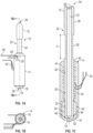
FIG. 1a is a side view of a nozzle for use in a 3D printer for manufacturing a 3D structure, in accordance with one aspect of the invention; -
FIG. 1b is an end view of the nozzle ofFIG. 1a illustrated in further detail, in accordance with an aspect of the present invention; -
FIG.1c is a cross-sectional view of the nozzle ofFIGS. 1a and 1b illustrated in further detail, in accordance with an aspect of the present invention; -
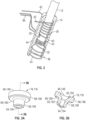
FIG. 2 is a perspective view of the heating element disposed on the barrel of the nozzle, in accordance with an aspect of the present invention; -
FIG. 3a is a perspective view of the end tip of the nozzle ofFIG. 1a , in accordance with an aspect of the present invention; -
FIG. 3b is a cross-sectional view of the end tip of the nozzle ofFIGS. 1a and3a , in accordance with an aspect of the present invention; -
FIG. 4a is a perspective view of the retaining cap of the nozzle ofFIG. 1a , in accordance with an aspect of the present invention; -
FIG. 4b is a cross-sectional view of the retaining cap of the nozzle ofFIGS. 1a and4a , in accordance with an aspect of the present invention; -
FIG. 5a is a front view of a nozzle, in accordance with an with an aspect of the present invention; -
FIG. 5b is a cross-sectional view of a nozzle, in accordance with an aspect of the present invention -
FIG. 6 is an exploded, cross-sectional view of a barrel and an end tip, in accordance with an aspect of the present invention; -
FIG. 7 is a cross-sectional view of a nozzle in accordance with an aspect of the present invention; -
FIG. 8 is a perspective view of a bifilar heating coil wrapped around a barrel in accordance with an aspect of the present invention; -
FIG. 9a is a perspective view of a retaining cap in accordance with an aspect of the present invention; -
FIG. 9b is a cross-sectional view of the retaining cap ofFIG. 9a in accordance with an aspect of the present invention; -
FIG. 10 is an exploded, perspective view of a nozzle in accordance with an aspect of the present invention; and -
FIG. 11 is a perspective view of a nozzle in accordance with an aspect of the present invention - The following description is merely exemplary in nature and is not intended to limit the present disclosure, application, or uses.
- The present invention provides a nozzle for receiving and dispensing a 3D filament to progressively build a 3D structure. The 3D filament is typically an elongated tubular member made of various polymer or non-polymer materials. The nozzle receives the 3D filament, heats the 3D filament and dispenses 3D filament onto a support platform. The 3D structure is formed by dispensing successive layers of the 3D filament material from the nozzle. A variety of different 3D filament materials may be used to build different 3D structures having different structural properties and appearances.
- Referring to
FIG. 1a , a side view of a nozzle 10 for use in a 3D printer for manufacturing a 3D structure is illustrated, in accordance with one aspect of the invention. Nozzle 10 is configured to receive, heat, and dispense a 3D printer filament. The 3D printer filament is fed into and received by the nozzle under pressure from an external filament feeding apparatus (not shown). - With continuing reference to
FIG. 1a and additional reference toFIG. 1b and FIG. 1c , end and cross-sectional views of nozzle 10 are illustrated in further detail, in accordance with an embodiment of the present invention. Nozzle 10 includes abarrel 12, aheating element 14, anend tip 16, a retainingcap 18 andtemperature sensor 20. -
Barrel 12 has an elongatedbody 22 having aninternal bore 24. Thebarrel 12 has afirst diameter portion 26, asecond diameter portion 28, athird diameter portion 30 and afourth diameter portion 32. Thefirst diameter portion 26 has a diameter that is greater than a diameter of thesecond diameter portion 28. Thethird diameter portion 30 has a diameter that is equal to the diameter of thefirst diameter portion 26. Thefourth diameter portion 32 has a diameter that is less than the diameter of thethird diameter portion 30. Thus,second diameter portion 28 is a necked down section ofelongated body 22 ofbarrel 12 having a length "n". The length "n" ofsecond diameter portion 28 is configured to allow the necked down section of theelongated body 22 to function as a heat break defined in theexterior surface 40 of thebarrel 12. A heat break may be understood as a feature, such as the necked down section of thesecond diameter portion 28, or a split in the barrel, which reduces the transfer of heat, such as by conduction, along the barrel. Further, cooling of thesecond diameter portion 28 along the length "n" is facilitated by the addition of cooling fins (not shown) adjacent or overlappingsecond diameter portion 28. - Internal bore 24 is a through bore running the extent of the
elongated body 22 and has afilament receiving end 34 and afilament discharge end 36. Thefilament receiving end 34 has a chamferededge 38 for facilitating the receipt of the 3D printer filament. Moreover,barrel 12 has anexterior surface 40 on which theheating element 14 is disposed. - With continuing reference to
FIG. 1c and additional reference toFIG. 2 , a perspective view of theheating element 14 disposed onbarrel 12 is illustrated in further detail, in accordance with an embodiment of the present invention. Theheating element 14 is disposed proximate thefilament discharge end 36 over theexterior surface 40 on thethird diameter portion 30 and at least overlapping a portion of thefourth diameter portion 32.Heating element 14 includes acontinuous heating wire 42 wrapped around theexterior surface 40 of thebarrel 12. Theheating wire 42 is a nickel-chrome wire or a titanium wire having spaced apartloops 43 around theexterior surface 40 along thethird diameter portion 30 and thefourth diameter portion 32 ofbarrel 12. - An insulating coating or
layer 44 of epoxy, fiberglass sheathing, a liquid ceramic, or the like is applied over and, in aspects, under the wrappedheating wire 42. In aspects, where a liquid ceramic is used, the insulation may be a coating, which is part of or on theexterior surface 40 of thebarrel 12 and proximal to thecoil 42. In aspects, insulatinglayer 44 could be one layer of epoxy, several layers of epoxy, or a coating on the barrel with liquid ceramic over that. The insulating coating orlayer 44 provides a protective electrically insulating covering over theloops 43 of theheating wire 42. Moreover,layer 44 may be several layers applied one after the other and provide heat insulating properties to aid in retaining and controlling the heat produced byheating wire 42 and transferred to thebarrel 12. - In aspects, the
heating wire 42 may be affixed at various locations or to wire leads leading to a power source or control system (not illustrated) by processes such as micro-welding. Micro-welding is understood as a tungsten inert gas (TIG) welding process or a laser welding process - capable of producing welds of less than 5 mm, including all values and ranges therein, such as 1 mm to 5 mm. - With continuing reference to
FIG. 1c and additional reference toFIGS. 3a and 3b , perspective and cross-sectional views of theend tip 16 are illustrated in further detail, in accordance with an embodiment of the present invention. Theend tip 16 is secured to the filament discharge end 36 ofbarrel 12. Theend tip 16 has afilament receiving end 46 adjacent the filament discharge end 36 of thebarrel 12. Thefilament receiving end 46 of theend tip 16 has a frustoconical shaped opening 50 as shown in a cross-section inFIGS. 1b and3b . The frustoconical shaped opening 50 transitions to astraight bore section 52 that terminates at a discharge orifice 54. Additionally, theend tip 16 has a first diameter section 56 that transitions to a second diameter section 58 forming an annular shelf 60 therebetween. The first diameter section 56 has a larger diameter than the diameter of the second diameter section 58.End tip 16 is made of ruby, sapphire, carbide, ceramic, steel, glass, quartz or the like. An improved extrusion is achieved withend tip 16 through greater adjustability of heat transfer from theheating element 14 to the 3D filament. A variety ofend tip 16 configurations are contemplated with different coatings, hardness, internal finish, polish, texture, and entry and exit profiles to control flow of the 3D filament. Aparticular end tip 16 configuration (i.e. material selection, internal finish, etc.) may be selected for a given 3D filament to ensure filament compatibility, adhesion and wearability of theend tip 16. Thus, the 3D filament is received in thefilament receiving end 34, is heated by theheating element 14, and is dispensed throughend tip 16 proximate thefilament discharge end 36. The ability to select the material properties and finishes, coatings, etc. of theend tip 16 allows the present invention to achieve longer run times without the need to replace theend tip 16. - With continuing reference to
FIG. 1c and additional reference toFIGS. 4a and 4b , perspective and cross-sectional views of the retainingcap 18 are illustrated in further detail, in accordance with an embodiment of the present invention. Retainingcap 18 is configured to mechanically secure theend tip 16 to thebarrel 12 and, in aspects the retainingcap 18 may be affixed to the barrel by, e.g., micro-welding. To that end, retainingcap 18 has a firstopen end 70 for receiving thebarrel 12 and a secondopen end 72 for receiving theend tip 16. Aninternal bore 74 connects the firstopen end 70 to the secondopen end 72 and has an inner diameter of sufficient dimension to accept the insertion of theend tip 16. More specifically, aninner surface 76 ofinternal bore 74 has a retention means such as an internal thread that engages an external thread on theexterior surface 40 of thebarrel 12 to secure the retainingcap 18 onbarrel 12. Alternatively,internal bore 74 is sized to create an interference or press fit with theexterior surface 40 of thebarrel 12. Anannular rim 78 of the secondopen end 72 of retainingcap 18 engages the shelf 60 ofend tip 16, thereby, capturing theend tip 16 in the retainingcap 18. Consequently, theend tip 16 is pressed or sandwiched between the retainingcap 18 and thebarrel 12 and the second diameter section 58 of theend tip 16 is received in the secondopen end 72 of the retainingcap 18. In aspects, the retainingcap 18 is micro-welded to thebarrel 12, which may improve performance under pressure and heating cycles. - With continuing reference to
FIGS. 1b, 1c , and2 , a perspective view of thetemperature sensor 20 disposed onbarrel 12 is illustrated in further detail, in accordance with an embodiment of the present invention. Thetemperature sensor 20 is disposed on theexterior surface 40 ofbarrel 12 for detecting the temperature of thebarrel 12 adjacent theinternal bore 24. The present invention contemplates the placement ofmultiple temperature sensors 20 along thebarrel 12, as shown inFIG. 1c .Temperature sensor 20 is attached to the third diameter portion ofbarrel 12 and in other embodiments of the present inventionadditional temperature sensors 20 are also attached to the fourth diameter portion ofbarrel 12. In aspects, thetemperature sensor 20 is attached with a polymer adhesive, metal-filled polymer adhesive, metal soldering/brazing material, or similar material, and in further aspects, includes a silver filled epoxy. The positioning of thetemperature sensors 20 at various locations alongbarrel 12 allow for greater control of the temperature profile alongbarrel 12. For example,temperature sensors 20 are in electrical communication though wire leads 90 with a control system (not shown) that includes control logic to activate theheating wire 42 to heat thebarrel 12 and sense the heat in thebarrel 12 with thetemperature sensors 20 and increase or decrease the heating of theheating wire 42 to achieve the desired temperature profile in thebarrel 12. It is noted that the wire leads 90 may be attached at various locations to thetemperature sensors 20 or to other wires, which improves durability, performance and safety. Again, attachment may be through micro-welding. It is noted, and further described herein, that one or more of thetemperature sensors 20 are, in aspects, applied in channels defined in theexterior surface 40 of thebarrel 12. A channel (see 124 inFIG. 6 ), allows thetemperature sensor 20 to sit closer to the interior bore 24, in some cases, less than 0.5 mm from theinternal bore 24, including all values and ranges, therein such as 0.1 mm to 0.5 mm, 0.3 mm, 0.2 mm, etc. -
FIGS. 5a and 5b illustrate a front view and a cross-sectional view of anozzle 110 for use in a 3D printer for manufacturing a 3D structure, in accordance with additional, interchangeable or alternative aspects of the invention. In the illustrated aspect and similar to the nozzle ofFIGS. 1a through 1c , thenozzle 110 includes abarrel 112, aheating element 114, anend tip 116, and atemperature sensor 120. - With continuing reference to
FIGS. 5a and 5b as well as with reference toFIG. 6 , which illustrates an exploded cross-sectional view of thebarrel 112 and retainingcap 118, thebarrel 112 has anelongated body 122 having aninternal bore 124. Further, thebarrel 112 has afirst diameter portion 126, at least onesecond diameter portion 128, athird diameter portion 130 and afourth diameter portion 132. Thefirst diameter portion 126 has a diameter that is greater than a diameter of thesecond diameter portion 128. Thethird diameter portion 130 has a diameter that is equal to the diameter of thefirst diameter portion 126. Thefourth diameter portion 132 has a diameter that is less than the diameter of thethird diameter portion 130. Thus,second diameter portion 128 is a necked down section ofelongated body 122 ofbarrel 112 having a length "n". The length "n" ofsecond diameter portion 128 is configured to allow the necked down section of theelongated body 122 to function as a heat break defined in theexterior surface 140 of thebarrel 112. Further, thesecond diameter portion 128 provides a feature for theclamp 216 andframe 218 to interlock with and prevent vertical movement of thebarrel 112 relative to theclamp 216 andframe 218 as further described herein and illustrated inFIGS. 5b ,10 and11 . - In the aspect presented in
FIG. 6 , thebarrel 112 is amulti-component barrel 112 includes afirst shank 180 and asecond shank 182, which together form theelongated body 122. Eachshank internal bore 124, which runs the extent of theelongated body 122, when thebarrel 112 is assembled. In aspects, thefirst shank 180 is affixed to thesecond shank 182, such as by micro-welding, which may provide improved performance under pressure and over a number of heating cycles. - The
first shank 180 includes thefilament receiving end 134. Thefilament receiving end 134 defines two opposingpeaks valleys opening 204 of thefilament receiving end 134. The interior offilament receiving end 134 also includes a chamferededge 138, which also facilitates the receipt of the 3D printer filament; thechamfered edge 138 extending from the opposingpeaks internal bore 124 beginning beneath the two opposingvalleys 200, 202 (further illustrated inFIG. 5a ). - In aspects, the
first shank 180 is formed out of stainless steel or ceramic and thesecond shank 182 is formed of aluminum or a separate piece of ceramic. In further aspects, thefirst shank 180 andsecond shank 182 are thermally isolated with coatings provided on thefirst shank 180, thesecond shank 182, or both the first andsecond shanks shanks second shanks nozzle 110 is heated, thefirst shank 180 is at a relatively second temperature than thesecond shank 182. - In addition, the
first shank 180 includes thefirst diameter portion 126, thesecond diameter portion 128, and acoupling portion 129. Again thesecond diameter portion 128 exhibits a smaller diameter than thefirst diameter portion 126 and thecoupling portion 129. In aspects, thefirst diameter portion 126 and thecoupling portion 129 are equal in diameter. Alternatively, thefirst diameter portion 126 and thecoupling portion 129 are of differing diameters. Thefirst shank 180 also includes anotch 206 defined in thecoupling portion 129 between thesecond diameter portion 128 and the end 208 of thefirst shank 180. Thenotch 206 has a diameter that is smaller than thesecond diameter portion 128 andcoupling portion 129. Further, in thecoupling portion 129, thefirst shank 180 defines a receiving bore 210, which receives thesecond shank 182. In aspects, the receiving bore 210 may extend through only a portion of thecoupling portion 129, being less than the length of thecoupling portion 129. In aspects, thesecond shank 182 is retained in the receiving bore 210 by an interference or friction fit. - The
second shank 182 includes athird diameter portion 130 and thefourth diameter portion 132, wherein the diameter of thefourth diameter portion 132 is less than that of thethird diameter portion 130. Thesecond shank 182 also includes amating portion 212, which is less than thethird diameter portion 130 and, in aspects, is the same diameter as thefourth diameter portion 132. Themating portion 212 is received in the receiving bore 210 and, as noted above is mechanically retained therein, such as by an interference fit. Thesecond shank 182 also includes thefilament discharge end 136. - In addition, in aspects, the
third diameter portion 130 of thesecond shank 182 includes achannel 214 formed therein in which at least onetemperature sensor 120 is positioned (SeeFIG. 7 ). It may be appreciated thatadditional temperature sensors 120 andadditional channels 214 may be provided. Thechannel 214 does not intersect with theinternal bore 124. Thechannel 214 allows thesensor 120 to be placed below the periphery of the remainder of theexternal surface 140, inside the heater element 114 (including theheater wire 142 and first insulating layer 145) for thermal reasons and places the sensing surface of the sensor relatively closer to the molten polymer in the barrel. In aspects, thechannel 214 allows thetemperature sensor 120 to sit less than 0.5 mm from theinterior surface 124 of thebarrel 112, including all values and ranges, therein such as 0.1 mm to 0.5 mm, 0.3 mm, 0.2 mm, etc. - With reference again to
FIGS. 5a, 5b ,7 and 8 , thebarrel 112 has anexterior surface 140 on which theheating element 114 is disposed. In aspects, theheating element 114 is positioned on thesecond shank 182. In aspects, theheating element 114 is the same asheating element 14 noted above. In the aspect illustrated inFIGS. 7 and 8 , theheating element 114 is aheating wire 142 formed into a bifilar coil, wherein the coil contains two parallel windings ofloops 143, formed by folding thecoil 142 in half creating aloop 141 in the coil, before winding the coil around thebarrel 112. Theheating wire 142 is formed from the same materials asheating wire 42. With attention now toFIG. 7 , a first insulating coating orlayer 145 is disposed over thebarrel 112 and a second insulating coating orlayer 144 is disposed over theheating element 114. The insulating coatings or layers 144, 145 includes, for example, coil fiber glass sheathing, an epoxy layer, an insulating ceramic layer, or the like. In aspects, multiple layers of the epoxy, fiber glass sheathing, ceramic or a combination thereof, are used to provide each of the insulatinglayers - With reference to
FIGS. 6 ,9a and 9b , theend tip 116 is secured to thefilament discharge end 136 of thebarrel 112 by a retainingcap 118. In addition, theend tip 116 may be affixed to thefilament discharge end 136 of the barrel by welding, such as by micro-welding. In the illustrated aspect, thesecond shank 182 of thebarrel 112 is seated in the retainingcap 118 at thefilament discharge end 136. The retainingcap 118, in the illustrated aspect, includes a firstopen end 170 for receiving thebarrel 112 and a secondopen end 172 for receiving theend tip 116. Aninternal bore 174 connects the firstopen end 170 to the secondopen end 172. Theinternal bore 174 also has an inner diameter of sufficient dimension to accept the insertion of the end tip 116 (seen inFIG. 7 ). In aspects, aninner surface 176 of theinternal bore 174 has a retention means such as an internal thread that engages an external thread on theexterior surface 140 of thebarrel 112 to secure the retainingcap 118 to thebarrel 112. Alternatively,internal bore 174 is sized to create an interference or press fit with theexterior surface 140 of thebarrel 112. Anannular rim 178 of the secondopen end 172 of the retainingcap 18 engages theshelf 160 ofend tip 116, thereby capturing theend tip 116 in the retainingcap 118. Consequently, theend tip 116 is pressed or sandwiched between the retainingcap 118 and thebarrel 112 and the second diameter section 158 of theend tip 116 is received in the secondopen end 172 of the retainingcap 118. In aspects, the retainingcap 118 is micro-welded to thebarrel 112, which may improve performance under pressure and heating cycles. In the illustrated aspect, the retainingcap 118 has atubular portion 175 that transitions to afrustoconical section 177. Thefourth diameter portion 132 of thesecond shank 182 is received in and extends through thetubular portion 175 of the retainingcap 118. In aspects, thefourth diameter portion 132 of thesecond shank 182 may also extend past thetubular portion 175 and into thefrustoconical portion 177 of the retainingcap 118, depending on the dimensions of theend tip 116. In addition, in aspects, theheating element 114 may extend over thetubular portion 175 of the retaining cap 118 (as seen inFIG. 5b ). The retainingcap 118 may also include anannular shelf 179 located at the transition of thetubular portion 175 and thefrustoconical portion 178. In aspects, theheat element 114 rests against theannular shelf 179 as seen inFIG. 7 . - The
end tip 116, in aspects, is the same as or similar to the end tip illustrated and described with respect toFIGS. 3a and 3b . Theend tip 116 is secured to thefilament discharge end 136 ofbarrel 112 and has a filament receiving end 146 adjacent thefilament discharge end 136 of thebarrel 112. The filament receiving end 146 of theend tip 116 has a frustoconical shaped opening 150 as shown in a cross-section inFIGS. 7 and3b . The frustoconical shaped opening 150 transitions to a straight bore section 152 that terminates at a discharge orifice 154. Additionally, theend tip 116 has a first diameter section 156 that transitions to a second diameter section 158 forming anannular shelf 160 therebetween. The first diameter section 156 has a larger diameter than the diameter of the second diameter section 158.End tip 116 is made of ruby, sapphire, carbide, ceramic, steel, glass, quartz or the like. An improved extrusion is achieved with theend tip 116 through greater adjustability of heat transfer from theheating element 114 to the 3D filament. A variety ofend tip 116 configurations are contemplated with different coatings, hardness, internal finish, polish, texture, and entry and exit profiles to control flow of the 3D filament. Aparticular end tip 116 configuration (i.e. material selection, internal finish, etc.) may be selected for a given 3D filament to ensure filament compatibility, adhesion and wearability of theend tip 116. Thus, the 3D filament is received in thefilament receiving end 134, is heated by theheating element 114, and is dispensed throughend tip 116 proximate thefilament discharge end 136. The ability to select the material properties and finishes, coatings, etc. of theend tip 116 allows the present invention to achieve longer run times without the need to replace theend tip 116. - Turning now to
FIGS. 7 and 8 , and as previously alluded to above, atemperature sensor 120 is disposed on theexterior surface 140 of thebarrel 112, and in particular, within thechannel 214 defined in thesecond shank 182 of thebarrel 112. Again, more than onetemperature sensors 120 may be present and eachtemperature sensor 120 may be located within itsown channel 214. Thetemperature sensor 120 is similar in nature and function totemperature sensor 20 noted above. - Turning now to
FIG. 10 and with continuing reference toFIGS. 5a and 5b , thenozzle 110 is retained in aframe 218 by aclamp 216, wherein thenozzle 110 is positioned between theframe 218 and theclamp 216. Theclamp 216 is mechanically fastened to theframe 218 bymechanical fasteners 220, such as bolts or welds. Further, aconnector block 220 is attached to theframe 218 and carries the wire leads 190, which connect thetemperature sensor 120 and heating element 114 (seeFIG. 5b ) to a control system, such as the control system noted above. The wire leads 190 may be affixed to thetemperature sensor 120 or at various locations or to other wires, which may improve reliability and durability. Methods of affixing the wire leads 190 include micro-welding. Theclamp 216 includes a plurality offins 217, which provide increased surface area to improve cooling of theclamp 216. The mountingsurface 219 of theframe 218 runs parallel to thebarrel 112.FIG. 11 illustrates an alternate aspect where the mountingsurface 219 of theframe 218 is perpendicular to thebarrel 112. In this aspect, theframe 218 may also include aclamp 221 formed with theframe 218 or affixed to theframe 218. - As may be appreciated and understood by a person having ordinary skill in the art, the various features may be interchangeable between the individual aspects described and illustrated herein. In one example, the chamfered
edge 138 ofFIGS. 5a and b may be substituted for the chamferededge 38 ofFIGS. 1a through 1c . In another example, the unitary barrel construction ofFIGS. 1a through 1c , may be substituted for the multi-component barrel construction ofFIGS. 5a and 5b . - The present invention further contemplates a method for receiving and dispensing a 3D printer filament. The method includes receiving the 3D printer filament, heating the 3D printer filament, dispensing the 3D printer filament. Moreover, with reference to
FIGS. 1a through 11 receiving the 3D printer filament includes using anozzle 10, 110 having abarrel internal bore exterior surface internal bore filament receiving end filament discharge end heating element filament discharge end heating element heating wire 42 wrapped around theexterior surface barrel end tip filament discharge end - In embodiments, the method further includes mechanically retaining the
end tip barrel cap end tip barrel cap barrel open end cap end tip open end cap end tip barrel end tip annular rim open end cap end tip barrel annular rim open end cap annular shelf 60, 160 of theend tip - In embodiments, the method includes mechanically retaining a
first shank 180 of thebarrel 112 to asecond shank 182 of thebarrel 112. In additional embodiments, the method includes retaining theend tip 116 to thesecond shank 182 of thebarrel 112 by micro-welds. - Additionally, the method, includes receiving the 3D printer filament in the
nozzle 10, 110 using abarrel first diameter portion second diameter portion third diameter portion fourth diameter portion barrel first diameter portion second diameter portion barrel third diameter portion first diameter portion barrel barrel 112 is amulti-component barrel 112 that includes afirst shank 180 and asecond shank 182, wherein heat is applied to thesecond shank 182 to inhibit the transfer of heat energy fromsecond shank 182 to thefirst shank 180. Thethird diameter portion first diameter portion fourth diameter portion third diameter portion cap - Subsequently, in embodiments, the 3D printer filament is dispensed with the
end tip filament receiving end 46, 146 positioned adjacent thefilament discharge end barrel filament receiving end 46, 146 has an opening 50, 150 having a frustoconical cross-section for facilitating the transition of the filament into theend tip bore 52, 152 adjacent afilament dispensing end end tip
Claims (15)
- A nozzle (10, 110) for receiving and dispensing a 3D printer filament, the nozzle (10, 110) comprising:a barrel (12, 112) having an internal bore (24, 124) and an exterior surface (40, 140), wherein the internal bore (24, 124) has a filament receiving end (34, 134) and a filament discharge end (36, 136);a heat break defined in the exterior surface (40, 140) of the barrel (12, 112);a heating element (14, 114) proximate the filament discharge end (36, 136), wherein the heating element (14, 114) includes a heating wire (42, 142) wrapped around the exterior surface (40, 140) of the barrel (12, 112); andan end tip (16, 116) proximate the filament discharge end (36, 136), and wherein the 3D filament received in the filament receiving end (34, 134) is heated by the heating element (14, 114) and dispensed through a discharge orifice (54, 154) in the end tip (16, 116);wherein the filament receiving end defines two opposing peaks (186, 188), and two opposing valleys (200, 202).
- The nozzle (10, 110) of claim 1, further comprising a retaining cap (18, 118) for mechanically retaining the end tip (16, 116) to the barrel (12, 112), wherein the retaining cap (18, 118) has a first open end (70, 170) for receiving the barrel (12, 112) and a second open end (72, 172) for receiving the end tip (16, 116).
- The nozzle (10, 110) of claim 1, wherein the barrel (12, 112) includes a first shank (180) and a second shank (182).
- The nozzle (10, 110) of claim 3, wherein the heating element (14, 114) is positioned on the second shank (182).
- The nozzle (10, 110) of claim 1, further comprising a temperature sensor (20, 120) attached to the exterior surface (40, 140) of the barrel (12, 112).
- The nozzle (10, 110) of claim 1, wherein the barrel (12, 112) has a first diameter portion (26, 126), a second diameter portion (28, 128), a third diameter portion (30, 130) and a fourth diameter portion (32, 132).
- The nozzle (10, 110) of claim 6, wherein the first diameter portion (26, 126) has a diameter that is greater than a diameter of the second diameter portion (28, 128).
- The nozzle (10, 110) of claim 7, wherein the third diameter portion (30, 130) has a diameter that is equal to the diameter of the first diameter portion (26, 126).
- The nozzle (10, 110) of claim 8, wherein the fourth diameter portion (32, 132) has a diameter that is less than the diameter of the third diameter portion (30, 130).
- The nozzle (10, 110) of claim 1, wherein the barrel (12, 112) and the end tip (16, 116) are received in an internal bore (24, 124) defined in a retaining cap (18, 118).
- The nozzle (10, 110) of claim 1, wherein the heating element (14, 114) includes a bifilar coil (42, 142).
- A method for receiving and dispensing a 3D printer filament, the method comprising:receiving the 3D printer filament using a nozzle (10, 110) having a barrel (12, 112) and an end tip (16, 116), the barrel (12, 112) including an internal bore (24, 124), an exterior surface (40, 140) and a heat break defined in the exterior surface (40, 140), wherein the internal bore (24, 124) has a filament receiving end (34, 134) and a filament discharge end (36, 136), the end tip (16, 116) being positioned proximate to the filament discharge end (36, 136);heating the 3D printer filament with a heating element (14, 114) proximate the filament discharge end (36, 136), wherein the heating element (14, 114) includes a heating wire (42, 142) wrapped around the exterior surface (40, 140) of the barrel (12, 112); anddispensing the 3D printer filament through a discharge orifice (54, 154) of the end tip (16, 116);wherein the filament receiving end defines two opposing peaks (186, 188), and two opposing valleys (200, 202).
- The method of claim 12, further comprising mechanically retaining the end tip (16, 116) to the barrel (12, 112) using a retaining cap (18, 118).
- The method of claim 13, wherein mechanically retaining the end tip (16, 116) to the barrel (12, 112) using the retaining cap (18, 118) further comprises receiving the barrel (12, 112) and end tip (16, 116) within a first open end (70, 170) of the retaining cap (18, 118), wherein the end tip (16, 116) extends through the retaining cap(18, 118).
- The method of claim 14, further comprising mechanically retaining a first shank(180) of the barrel (12, 112) to a second shank (182) of the barrel (12, 112).
Applications Claiming Priority (3)
| Application Number | Priority Date | Filing Date | Title |
|---|---|---|---|
| US201862703700P | 2018-07-26 | 2018-07-26 | |
| US16/268,873 US11440252B2 (en) | 2018-07-26 | 2019-02-06 | High speed extrusion 3D printer nozzle |
| PCT/US2019/043427 WO2020023739A1 (en) | 2018-07-26 | 2019-07-25 | High speed extrusion 3d printer nozzle |
Publications (3)
| Publication Number | Publication Date |
|---|---|
| EP3814090A1 EP3814090A1 (en) | 2021-05-05 |
| EP3814090A4 EP3814090A4 (en) | 2022-03-23 |
| EP3814090B1 true EP3814090B1 (en) | 2023-09-06 |
Family
ID=69179704
Family Applications (1)
| Application Number | Title | Priority Date | Filing Date |
|---|---|---|---|
| EP19840371.9A Active EP3814090B1 (en) | 2018-07-26 | 2019-07-25 | High speed extrusion 3d printer nozzle |
Country Status (7)
| Country | Link |
|---|---|
| US (2) | US11440252B2 (en) |
| EP (1) | EP3814090B1 (en) |
| KR (1) | KR102539388B1 (en) |
| CN (1) | CN112512774B (en) |
| CA (1) | CA3107073A1 (en) |
| SG (1) | SG11202100454XA (en) |
| WO (1) | WO2020023739A1 (en) |
Families Citing this family (13)
| Publication number | Priority date | Publication date | Assignee | Title |
|---|---|---|---|---|
| US11760001B2 (en) | 2019-03-29 | 2023-09-19 | Stratasys, Inc. | Filament supply with sealed connector for use with a 3D printer |
| USD938258S1 (en) * | 2019-03-29 | 2021-12-14 | Stratasys, Inc. | Key for a filament feed tube |
| USD938259S1 (en) * | 2019-03-29 | 2021-12-14 | Stratasys, Inc. | Key for a filament feed tube |
| US11370164B1 (en) | 2019-06-27 | 2022-06-28 | Jacob J. Consalvi | High speed FDM 3D printer with closed loop motion system |
| WO2022047133A1 (en) * | 2020-08-31 | 2022-03-03 | Essentium, Inc. | Nozzle for producing extrusion three-dimensional printed materials |
| JP7476746B2 (en) * | 2020-09-30 | 2024-05-01 | セイコーエプソン株式会社 | Three-dimensional modeling device and three-dimensional modeling system |
| FR3118599B1 (en) * | 2021-01-07 | 2023-04-28 | Bombix3D | Three-dimensional printing device with stabilized temperature of the print head |
| EP4319966B1 (en) * | 2021-04-07 | 2025-10-15 | US Synthetic Corporation | Nozzles including polycrystalline diamond or polycrystalline cubic boron nitride and related assemblies and methods |
| KR20230012195A (en) * | 2021-07-15 | 2023-01-26 | 현대자동차주식회사 | Apparatus and Method for 3D Printing |
| CN113910409B (en) * | 2021-10-27 | 2023-04-11 | 吴东蔚 | Remote extrusion device for 3D printing equipment |
| WO2023086921A1 (en) * | 2021-11-12 | 2023-05-19 | Essentium Ipco, Llc | Three-dimensional printer head having dual extruders sharing a common drive motor |
| JP2024032159A (en) * | 2022-08-29 | 2024-03-12 | セイコーエプソン株式会社 | Material dispensing equipment, nozzles and plasticizing equipment |
| CN115709565B (en) * | 2022-11-04 | 2025-06-17 | 杭州喜马拉雅信息科技有限公司 | A 3D printing anti-deformation wire feeding device |
Family Cites Families (59)
| Publication number | Priority date | Publication date | Assignee | Title |
|---|---|---|---|---|
| US2808623A (en) | 1953-10-30 | 1957-10-08 | Westinghouse Electric Corp | Method for casting tubular members |
| US2875311A (en) | 1956-02-14 | 1959-02-24 | Robert J Harkenrider | Induction heating in injection and extrusion processes |
| US3055053A (en) | 1959-11-12 | 1962-09-25 | Du Pont | Temperature gradient screw melter |
| US6022210A (en) * | 1995-01-31 | 2000-02-08 | Gunther Heisskanaltechnik Gmbh | Hot runner nozzle |
| US20040140292A1 (en) | 2002-10-21 | 2004-07-22 | Kelley John E. | Micro-welded gun barrel coatings |
| US7335864B2 (en) | 2005-06-01 | 2008-02-26 | Mrl Industries, Inc. | Magnetic field reduction resistive heating elements |
| US7384255B2 (en) * | 2005-07-01 | 2008-06-10 | Stratasys, Inc. | Rapid prototyping system with controlled material feedstock |
| US8236227B2 (en) | 2009-09-30 | 2012-08-07 | Stratasys, Inc. | Method for building three-dimensional models in extrusion-based digital manufacturing systems using tracked filaments |
| JP5902096B2 (en) | 2009-11-13 | 2016-04-13 | ソネンド インコーポレイテッド | Liquid jetting apparatus and method for dental treatment |
| US9022769B2 (en) | 2010-07-22 | 2015-05-05 | Stratasys, Inc. | Multiple-zone liquefier assembly for extrusion-based additive manufacturing systems |
| US8512024B2 (en) | 2011-01-20 | 2013-08-20 | Makerbot Industries, Llc | Multi-extruder |
| US9321608B2 (en) | 2011-12-22 | 2016-04-26 | Stratasys, Inc. | Spool assembly with locking mechanism for additive manufacturing system, and methods of use thereof |
| US9073263B2 (en) | 2011-12-22 | 2015-07-07 | Stratasys, Inc. | Spool assembly for additive manufacturing system, and methods of manufacture and use thereof |
| EP2626192A1 (en) | 2012-02-09 | 2013-08-14 | FIT Fruth Innovative Technologien GmbH | Modelling material and method and device for producing a three-dimensional object by melt layering |
| US9050753B2 (en) | 2012-03-16 | 2015-06-09 | Stratasys, Inc. | Liquefier assembly having inlet liner for use in additive manufacturing system |
| US9113501B2 (en) | 2012-05-25 | 2015-08-18 | Watlow Electric Manufacturing Company | Variable pitch resistance coil heater |
| GB201304968D0 (en) | 2013-03-19 | 2013-05-01 | Eads Uk Ltd | Extrusion-based additive manufacturing |
| US9126365B1 (en) | 2013-03-22 | 2015-09-08 | Markforged, Inc. | Methods for composite filament fabrication in three dimensional printing |
| CN103350507B (en) | 2013-04-04 | 2017-11-07 | 吴洁 | 3 D-printing pen |
| WO2015077262A1 (en) | 2013-11-19 | 2015-05-28 | Guill Tool & Engineering | Coextruded, multilayered and multicomponent 3d printing inputs |
| US20150183164A1 (en) | 2013-12-30 | 2015-07-02 | Chad E. Duty | Rapid electro-magnetic heating of nozzle in polymer extrusion based deposition for additive manufacturing |
| US9339975B2 (en) | 2013-12-31 | 2016-05-17 | Nike, Inc. | 3D printer with native spherical control |
| CN203779867U (en) | 2014-01-15 | 2014-08-20 | 南京亚弘电气科技有限公司 | Annular heating head of 3D printer extruding machine |
| EP3113923A1 (en) | 2014-03-04 | 2017-01-11 | Vito Galati | Heating sleeve for injection molding nozzle |
| US10343349B2 (en) | 2014-03-30 | 2019-07-09 | Stanley Korn | System, method and apparatus for 3D printing |
| JP2015202593A (en) | 2014-04-11 | 2015-11-16 | セイコーエプソン株式会社 | Supply mechanism of molding material and molding device |
| US20150298393A1 (en) | 2014-04-22 | 2015-10-22 | Thomas William Suarez | 3d printer system having a rotatable platform, metal flake filament, multiple heaters, and modularity |
| US9676159B2 (en) * | 2014-05-09 | 2017-06-13 | Nike, Inc. | Method for forming three-dimensional structures with different material portions |
| FR3022826A1 (en) | 2014-06-27 | 2016-01-01 | Zeepro France | MECHANISM FOR DRIVING AND GUIDING A FILAMENT FOR A 3D PRINTER |
| JP2017528340A (en) | 2014-07-22 | 2017-09-28 | ストラタシス,インコーポレイテッド | Geared liquefaction assembly for additive manufacturing system and method of use thereof |
| WO2016019049A1 (en) | 2014-07-29 | 2016-02-04 | Nscrypt, Inc. | Method and apparatus for 3d fabrication |
| US9931778B2 (en) | 2014-09-18 | 2018-04-03 | The Boeing Company | Extruded deposition of fiber reinforced polymers |
| US10766802B2 (en) | 2014-11-29 | 2020-09-08 | National Tsing Hua University | Flexible 3D freeform techniques |
| NL2014044B9 (en) | 2014-12-23 | 2017-03-29 | Bond High Performance 3D Tech B V | Deposition print head. |
| KR20160120538A (en) | 2015-04-08 | 2016-10-18 | 주식회사 쓰리디아이템즈 | Method and apparatus for building three dimensional objects |
| US20160318246A1 (en) | 2015-04-29 | 2016-11-03 | Orlando RIOS | Electromagnetic blunting of defects within fused deposition modeling (fdm)components |
| US10611138B2 (en) | 2015-08-28 | 2020-04-07 | Cosine Additive Inc. | Nozzle system with monolithic nozzle head for fused filament fabrication additive manufacturing and method of manufacturing same |
| NL2015512B1 (en) | 2015-09-28 | 2017-04-20 | Ultimaker Bv | Inductive nozzle heating assembly. |
| WO2017088754A1 (en) | 2015-11-24 | 2017-06-01 | Hummingbird Innovations Limited | Filament drive assembly for additive manufacturing device |
| DE102015016455A1 (en) | 2015-12-21 | 2017-06-22 | Universität Augsburg | System combination for 2D or 3D printing with an ionic liquid and ionic liquid |
| US10150249B2 (en) | 2015-12-29 | 2018-12-11 | Western Digital Technologies, Inc. | Dual head extruder for three-dimensional additive printer |
| US20170190109A1 (en) | 2015-12-30 | 2017-07-06 | Makerbot Industries, Llc | Multi-filament three-dimensional printing |
| US11110540B2 (en) | 2016-05-02 | 2021-09-07 | Electronics And Telecommunications Research Institute | Extruder for metal material and 3D printer using the same |
| US20170326773A1 (en) | 2016-05-16 | 2017-11-16 | Ord Solutions Inc. | Fused filament fabrication color extruder for three dimensional printing |
| NL2017016B1 (en) | 2016-06-21 | 2018-01-04 | Ultimaker Bv | Nozzle for a three dimensional printing apparatus |
| WO2018026909A1 (en) | 2016-08-05 | 2018-02-08 | Jabil Inc. | Apparatus, system and method of providing a fff printing nozzle |
| CN206425551U (en) | 2016-10-12 | 2017-08-22 | 机械科学研究总院先进制造技术研究中心 | A kind of melting extrusion building mortion suitable for various metals material |
| WO2018132157A2 (en) | 2016-11-03 | 2018-07-19 | Essentium Materials, Llc | Three dimensional printer apparatus |
| TWI602765B (en) | 2016-12-02 | 2017-10-21 | 財團法人工業技術研究院 | Extruder and variable nozzle device |
| CN206367193U (en) | 2016-12-15 | 2017-08-01 | 浙江大学 | A kind of fusion sediment type 3D printer of fast changeable printing head |
| CN206264352U (en) | 2016-12-22 | 2017-06-20 | 东莞市皇龙电子有限公司 | 3D printer print head adjustment structure |
| KR101796890B1 (en) | 2017-01-31 | 2017-11-13 | 전남대학교산학협력단 | Exchangeable extruder for three dimensional printer |
| US11254055B2 (en) | 2017-04-21 | 2022-02-22 | Hewlett-Packard Development Company, L.P. | Additive manufacturing machine heat flux |
| US11547849B2 (en) * | 2017-06-07 | 2023-01-10 | Neuronexus Technologies, Inc. | Systems and methods for ruggedized penetrating medical electrode arrays |
| US10688588B2 (en) | 2017-06-12 | 2020-06-23 | Raytheon Technologies Corporation | Continuous feed spindle attachment |
| US20190047225A1 (en) | 2017-08-09 | 2019-02-14 | Tyco Connectivity Corporation | Additive manufacturing apparatus and method for delivering material to a discharge pump |
| US10919221B2 (en) | 2017-10-03 | 2021-02-16 | Jabil Inc. | Apparatus, system and method for an additive manufacturing print head |
| US11485088B2 (en) * | 2017-10-03 | 2022-11-01 | Jabil Inc. | Apparatus, system and method of process monitoring and control in an additive manufacturing environment |
| US11584078B2 (en) | 2017-10-03 | 2023-02-21 | Jabil Inc. | Apparatus, system and method of operating an additive manufacturing nozzle |
-
2019
- 2019-02-06 US US16/268,873 patent/US11440252B2/en active Active
- 2019-07-25 SG SG11202100454XA patent/SG11202100454XA/en unknown
- 2019-07-25 KR KR1020217004096A patent/KR102539388B1/en active Active
- 2019-07-25 EP EP19840371.9A patent/EP3814090B1/en active Active
- 2019-07-25 CN CN201980049936.4A patent/CN112512774B/en not_active Expired - Fee Related
- 2019-07-25 WO PCT/US2019/043427 patent/WO2020023739A1/en not_active Ceased
- 2019-07-25 CA CA3107073A patent/CA3107073A1/en active Pending
-
2022
- 2022-08-03 US US17/817,126 patent/US20220371269A1/en active Pending
Also Published As
| Publication number | Publication date |
|---|---|
| KR102539388B1 (en) | 2023-06-02 |
| EP3814090A4 (en) | 2022-03-23 |
| CA3107073A1 (en) | 2020-01-30 |
| CN112512774B (en) | 2023-05-23 |
| KR20210029259A (en) | 2021-03-15 |
| EP3814090A1 (en) | 2021-05-05 |
| US20200031046A1 (en) | 2020-01-30 |
| SG11202100454XA (en) | 2021-02-25 |
| US11440252B2 (en) | 2022-09-13 |
| US20220371269A1 (en) | 2022-11-24 |
| WO2020023739A1 (en) | 2020-01-30 |
| CN112512774A (en) | 2021-03-16 |
Similar Documents
| Publication | Publication Date | Title |
|---|---|---|
| US20220371269A1 (en) | High speed extrusion 3d printer nozzle | |
| US4667084A (en) | Electrically heated hose for heating melted adhesive and atomizing air fed to a spraying head | |
| US9481933B2 (en) | Coaxial laser assisted cold spray nozzle | |
| US20040222209A1 (en) | Molding system with integrated film heaters and sensors | |
| EP1294553B2 (en) | Thermally balanced hot runner nozzle | |
| CA2022124A1 (en) | Insulated injection molding nozzle | |
| CN1061559A (en) | Injection molding nozzle with tapered heating element at valve orifice | |
| CA2368295C (en) | Welding contact tip with rolled threads | |
| EP3663073A1 (en) | 3d print head system with combined processing portions and an integrally integrally formed processing channel for additive manufacturing | |
| CA2425697C (en) | Metallic overcoat for thick film heater termination | |
| EP3289271B1 (en) | Joining method | |
| US20060104331A1 (en) | Device for measuring, monitoring and/or controlling a temperature | |
| EP1472067B1 (en) | Injection moulding apparatus with nozzle having a heated head portion | |
| US7367796B2 (en) | Heating cylinder for attachment to an injection nozzle for an injection molding system | |
| US20230321906A1 (en) | Nozzle for producing extrusion three-dimensional printed materials | |
| EP1622728B1 (en) | Hvof wire spray system | |
| US20220053612A1 (en) | Heater element incorporating primary conductor for use in a high-speed oven | |
| WO2004113044A2 (en) | Hot runner component heater having thermal sprayed resistive element | |
| US20210187844A1 (en) | Display screen with a graphical user interface | |
| AU2006203438B2 (en) | Heating cylinder for attachment to an injection nozzle for an injection molding system | |
| MXPA06009277A (en) | Heating cylinder for attachment to an injection nozzle molding system. | |
| KR20100052627A (en) | Torch cable for welding | |
| TR201510831A2 (en) | HARD ANODIZED GAS DISTRIBUTOR | |
| GB2406303A (en) | An electric welding fitting |
Legal Events
| Date | Code | Title | Description |
|---|---|---|---|
| STAA | Information on the status of an ep patent application or granted ep patent |
Free format text: STATUS: THE INTERNATIONAL PUBLICATION HAS BEEN MADE |
|
| PUAI | Public reference made under article 153(3) epc to a published international application that has entered the european phase |
Free format text: ORIGINAL CODE: 0009012 |
|
| STAA | Information on the status of an ep patent application or granted ep patent |
Free format text: STATUS: REQUEST FOR EXAMINATION WAS MADE |
|
| 17P | Request for examination filed |
Effective date: 20210126 |
|
| AK | Designated contracting states |
Kind code of ref document: A1 Designated state(s): AL AT BE BG CH CY CZ DE DK EE ES FI FR GB GR HR HU IE IS IT LI LT LU LV MC MK MT NL NO PL PT RO RS SE SI SK SM TR |
|
| DAV | Request for validation of the european patent (deleted) | ||
| DAX | Request for extension of the european patent (deleted) | ||
| A4 | Supplementary search report drawn up and despatched |
Effective date: 20220217 |
|
| RIC1 | Information provided on ipc code assigned before grant |
Ipc: B33Y 30/00 20150101ALI20220211BHEP Ipc: B33Y 10/00 20150101ALI20220211BHEP Ipc: B22F 12/53 20210101ALI20220211BHEP Ipc: B22F 10/18 20210101ALI20220211BHEP Ipc: B29C 64/118 20170101ALI20220211BHEP Ipc: B29C 64/209 20170101AFI20220211BHEP |
|
| REG | Reference to a national code |
Ref country code: DE Ipc: B29C0064209000 Ref legal event code: R079 Ref document number: 602019037038 Country of ref document: DE Free format text: PREVIOUS MAIN CLASS: B29C0048020000 |
|
| RIC1 | Information provided on ipc code assigned before grant |
Ipc: B23K 26/342 20140101ALI20230106BHEP Ipc: B23K 26/14 19800101ALI20230106BHEP Ipc: B23K 9/173 19900101ALI20230106BHEP Ipc: B23K 9/167 19900101ALI20230106BHEP Ipc: B23K 9/04 19680901ALI20230106BHEP Ipc: B33Y 30/00 20150101ALI20230106BHEP Ipc: B33Y 10/00 20150101ALI20230106BHEP Ipc: B22F 12/53 20210101ALI20230106BHEP Ipc: B22F 10/18 20210101ALI20230106BHEP Ipc: B29C 64/118 20170101ALI20230106BHEP Ipc: B29C 64/209 20170101AFI20230106BHEP |
|
| GRAP | Despatch of communication of intention to grant a patent |
Free format text: ORIGINAL CODE: EPIDOSNIGR1 |
|
| STAA | Information on the status of an ep patent application or granted ep patent |
Free format text: STATUS: GRANT OF PATENT IS INTENDED |
|
| INTG | Intention to grant announced |
Effective date: 20230224 |
|
| GRAS | Grant fee paid |
Free format text: ORIGINAL CODE: EPIDOSNIGR3 |
|
| GRAA | (expected) grant |
Free format text: ORIGINAL CODE: 0009210 |
|
| STAA | Information on the status of an ep patent application or granted ep patent |
Free format text: STATUS: THE PATENT HAS BEEN GRANTED |
|
| AK | Designated contracting states |
Kind code of ref document: B1 Designated state(s): AL AT BE BG CH CY CZ DE DK EE ES FI FR GB GR HR HU IE IS IT LI LT LU LV MC MK MT NL NO PL PT RO RS SE SI SK SM TR |
|
| REG | Reference to a national code |
Ref country code: GB Ref legal event code: FG4D |
|
| REG | Reference to a national code |
Ref country code: CH Ref legal event code: EP |
|
| REG | Reference to a national code |
Ref country code: IE Ref legal event code: FG4D |
|
| REG | Reference to a national code |
Ref country code: DE Ref legal event code: R096 Ref document number: 602019037038 Country of ref document: DE |
|
| REG | Reference to a national code |
Ref country code: LT Ref legal event code: MG9D |
|
| REG | Reference to a national code |
Ref country code: NL Ref legal event code: MP Effective date: 20230906 |
|
| PG25 | Lapsed in a contracting state [announced via postgrant information from national office to epo] |
Ref country code: GR Free format text: LAPSE BECAUSE OF FAILURE TO SUBMIT A TRANSLATION OF THE DESCRIPTION OR TO PAY THE FEE WITHIN THE PRESCRIBED TIME-LIMIT Effective date: 20231207 |
|
| PG25 | Lapsed in a contracting state [announced via postgrant information from national office to epo] |
Ref country code: SE Free format text: LAPSE BECAUSE OF FAILURE TO SUBMIT A TRANSLATION OF THE DESCRIPTION OR TO PAY THE FEE WITHIN THE PRESCRIBED TIME-LIMIT Effective date: 20230906 Ref country code: RS Free format text: LAPSE BECAUSE OF FAILURE TO SUBMIT A TRANSLATION OF THE DESCRIPTION OR TO PAY THE FEE WITHIN THE PRESCRIBED TIME-LIMIT Effective date: 20230906 Ref country code: NO Free format text: LAPSE BECAUSE OF FAILURE TO SUBMIT A TRANSLATION OF THE DESCRIPTION OR TO PAY THE FEE WITHIN THE PRESCRIBED TIME-LIMIT Effective date: 20231206 Ref country code: LV Free format text: LAPSE BECAUSE OF FAILURE TO SUBMIT A TRANSLATION OF THE DESCRIPTION OR TO PAY THE FEE WITHIN THE PRESCRIBED TIME-LIMIT Effective date: 20230906 Ref country code: LT Free format text: LAPSE BECAUSE OF FAILURE TO SUBMIT A TRANSLATION OF THE DESCRIPTION OR TO PAY THE FEE WITHIN THE PRESCRIBED TIME-LIMIT Effective date: 20230906 Ref country code: HR Free format text: LAPSE BECAUSE OF FAILURE TO SUBMIT A TRANSLATION OF THE DESCRIPTION OR TO PAY THE FEE WITHIN THE PRESCRIBED TIME-LIMIT Effective date: 20230906 Ref country code: GR Free format text: LAPSE BECAUSE OF FAILURE TO SUBMIT A TRANSLATION OF THE DESCRIPTION OR TO PAY THE FEE WITHIN THE PRESCRIBED TIME-LIMIT Effective date: 20231207 Ref country code: FI Free format text: LAPSE BECAUSE OF FAILURE TO SUBMIT A TRANSLATION OF THE DESCRIPTION OR TO PAY THE FEE WITHIN THE PRESCRIBED TIME-LIMIT Effective date: 20230906 |
|
| REG | Reference to a national code |
Ref country code: AT Ref legal event code: MK05 Ref document number: 1607958 Country of ref document: AT Kind code of ref document: T Effective date: 20230906 |
|
| PG25 | Lapsed in a contracting state [announced via postgrant information from national office to epo] |
Ref country code: NL Free format text: LAPSE BECAUSE OF FAILURE TO SUBMIT A TRANSLATION OF THE DESCRIPTION OR TO PAY THE FEE WITHIN THE PRESCRIBED TIME-LIMIT Effective date: 20230906 |
|
| PG25 | Lapsed in a contracting state [announced via postgrant information from national office to epo] |
Ref country code: IS Free format text: LAPSE BECAUSE OF FAILURE TO SUBMIT A TRANSLATION OF THE DESCRIPTION OR TO PAY THE FEE WITHIN THE PRESCRIBED TIME-LIMIT Effective date: 20240106 |
|
| PG25 | Lapsed in a contracting state [announced via postgrant information from national office to epo] |
Ref country code: AT Free format text: LAPSE BECAUSE OF FAILURE TO SUBMIT A TRANSLATION OF THE DESCRIPTION OR TO PAY THE FEE WITHIN THE PRESCRIBED TIME-LIMIT Effective date: 20230906 |
|
| PG25 | Lapsed in a contracting state [announced via postgrant information from national office to epo] |
Ref country code: ES Free format text: LAPSE BECAUSE OF FAILURE TO SUBMIT A TRANSLATION OF THE DESCRIPTION OR TO PAY THE FEE WITHIN THE PRESCRIBED TIME-LIMIT Effective date: 20230906 |
|
| PG25 | Lapsed in a contracting state [announced via postgrant information from national office to epo] |
Ref country code: SM Free format text: LAPSE BECAUSE OF FAILURE TO SUBMIT A TRANSLATION OF THE DESCRIPTION OR TO PAY THE FEE WITHIN THE PRESCRIBED TIME-LIMIT Effective date: 20230906 Ref country code: RO Free format text: LAPSE BECAUSE OF FAILURE TO SUBMIT A TRANSLATION OF THE DESCRIPTION OR TO PAY THE FEE WITHIN THE PRESCRIBED TIME-LIMIT Effective date: 20230906 Ref country code: IS Free format text: LAPSE BECAUSE OF FAILURE TO SUBMIT A TRANSLATION OF THE DESCRIPTION OR TO PAY THE FEE WITHIN THE PRESCRIBED TIME-LIMIT Effective date: 20240106 Ref country code: ES Free format text: LAPSE BECAUSE OF FAILURE TO SUBMIT A TRANSLATION OF THE DESCRIPTION OR TO PAY THE FEE WITHIN THE PRESCRIBED TIME-LIMIT Effective date: 20230906 Ref country code: EE Free format text: LAPSE BECAUSE OF FAILURE TO SUBMIT A TRANSLATION OF THE DESCRIPTION OR TO PAY THE FEE WITHIN THE PRESCRIBED TIME-LIMIT Effective date: 20230906 Ref country code: CZ Free format text: LAPSE BECAUSE OF FAILURE TO SUBMIT A TRANSLATION OF THE DESCRIPTION OR TO PAY THE FEE WITHIN THE PRESCRIBED TIME-LIMIT Effective date: 20230906 Ref country code: AT Free format text: LAPSE BECAUSE OF FAILURE TO SUBMIT A TRANSLATION OF THE DESCRIPTION OR TO PAY THE FEE WITHIN THE PRESCRIBED TIME-LIMIT Effective date: 20230906 Ref country code: PT Free format text: LAPSE BECAUSE OF FAILURE TO SUBMIT A TRANSLATION OF THE DESCRIPTION OR TO PAY THE FEE WITHIN THE PRESCRIBED TIME-LIMIT Effective date: 20240108 Ref country code: SK Free format text: LAPSE BECAUSE OF FAILURE TO SUBMIT A TRANSLATION OF THE DESCRIPTION OR TO PAY THE FEE WITHIN THE PRESCRIBED TIME-LIMIT Effective date: 20230906 |
|
| PG25 | Lapsed in a contracting state [announced via postgrant information from national office to epo] |
Ref country code: PL Free format text: LAPSE BECAUSE OF FAILURE TO SUBMIT A TRANSLATION OF THE DESCRIPTION OR TO PAY THE FEE WITHIN THE PRESCRIBED TIME-LIMIT Effective date: 20230906 Ref country code: IT Free format text: LAPSE BECAUSE OF FAILURE TO SUBMIT A TRANSLATION OF THE DESCRIPTION OR TO PAY THE FEE WITHIN THE PRESCRIBED TIME-LIMIT Effective date: 20230906 |
|
| REG | Reference to a national code |
Ref country code: DE Ref legal event code: R097 Ref document number: 602019037038 Country of ref document: DE |
|
| PG25 | Lapsed in a contracting state [announced via postgrant information from national office to epo] |
Ref country code: DK Free format text: LAPSE BECAUSE OF FAILURE TO SUBMIT A TRANSLATION OF THE DESCRIPTION OR TO PAY THE FEE WITHIN THE PRESCRIBED TIME-LIMIT Effective date: 20230906 |
|
| PLBE | No opposition filed within time limit |
Free format text: ORIGINAL CODE: 0009261 |
|
| STAA | Information on the status of an ep patent application or granted ep patent |
Free format text: STATUS: NO OPPOSITION FILED WITHIN TIME LIMIT |
|
| PG25 | Lapsed in a contracting state [announced via postgrant information from national office to epo] |
Ref country code: DK Free format text: LAPSE BECAUSE OF FAILURE TO SUBMIT A TRANSLATION OF THE DESCRIPTION OR TO PAY THE FEE WITHIN THE PRESCRIBED TIME-LIMIT Effective date: 20230906 Ref country code: SI Free format text: LAPSE BECAUSE OF FAILURE TO SUBMIT A TRANSLATION OF THE DESCRIPTION OR TO PAY THE FEE WITHIN THE PRESCRIBED TIME-LIMIT Effective date: 20230906 |
|
| 26N | No opposition filed |
Effective date: 20240607 |
|
| PG25 | Lapsed in a contracting state [announced via postgrant information from national office to epo] |
Ref country code: BG Free format text: LAPSE BECAUSE OF FAILURE TO SUBMIT A TRANSLATION OF THE DESCRIPTION OR TO PAY THE FEE WITHIN THE PRESCRIBED TIME-LIMIT Effective date: 20230906 |
|
| PG25 | Lapsed in a contracting state [announced via postgrant information from national office to epo] |
Ref country code: BG Free format text: LAPSE BECAUSE OF FAILURE TO SUBMIT A TRANSLATION OF THE DESCRIPTION OR TO PAY THE FEE WITHIN THE PRESCRIBED TIME-LIMIT Effective date: 20230906 |
|
| REG | Reference to a national code |
Ref country code: DE Ref legal event code: R119 Ref document number: 602019037038 Country of ref document: DE |
|
| PG25 | Lapsed in a contracting state [announced via postgrant information from national office to epo] |
Ref country code: MC Free format text: LAPSE BECAUSE OF FAILURE TO SUBMIT A TRANSLATION OF THE DESCRIPTION OR TO PAY THE FEE WITHIN THE PRESCRIBED TIME-LIMIT Effective date: 20230906 |
|
| REG | Reference to a national code |
Ref country code: CH Ref legal event code: PL |
|
| PG25 | Lapsed in a contracting state [announced via postgrant information from national office to epo] |
Ref country code: LU Free format text: LAPSE BECAUSE OF NON-PAYMENT OF DUE FEES Effective date: 20240725 |
|
| GBPC | Gb: european patent ceased through non-payment of renewal fee |
Effective date: 20240725 |
|
| PG25 | Lapsed in a contracting state [announced via postgrant information from national office to epo] |
Ref country code: LU Free format text: LAPSE BECAUSE OF NON-PAYMENT OF DUE FEES Effective date: 20240725 |
|
| PG25 | Lapsed in a contracting state [announced via postgrant information from national office to epo] |
Ref country code: DE Free format text: LAPSE BECAUSE OF NON-PAYMENT OF DUE FEES Effective date: 20250201 |
|
| PG25 | Lapsed in a contracting state [announced via postgrant information from national office to epo] |
Ref country code: BE Free format text: LAPSE BECAUSE OF NON-PAYMENT OF DUE FEES Effective date: 20240731 Ref country code: CH Free format text: LAPSE BECAUSE OF NON-PAYMENT OF DUE FEES Effective date: 20240731 |
|
| PG25 | Lapsed in a contracting state [announced via postgrant information from national office to epo] |
Ref country code: FR Free format text: LAPSE BECAUSE OF NON-PAYMENT OF DUE FEES Effective date: 20240731 |
|
| PG25 | Lapsed in a contracting state [announced via postgrant information from national office to epo] |
Ref country code: GB Free format text: LAPSE BECAUSE OF NON-PAYMENT OF DUE FEES Effective date: 20240725 |
|
| REG | Reference to a national code |
Ref country code: BE Ref legal event code: MM Effective date: 20240731 |
|
| PG25 | Lapsed in a contracting state [announced via postgrant information from national office to epo] |
Ref country code: IE Free format text: LAPSE BECAUSE OF NON-PAYMENT OF DUE FEES Effective date: 20240725 |
|
| PG25 | Lapsed in a contracting state [announced via postgrant information from national office to epo] |
Ref country code: CY Free format text: LAPSE BECAUSE OF FAILURE TO SUBMIT A TRANSLATION OF THE DESCRIPTION OR TO PAY THE FEE WITHIN THE PRESCRIBED TIME-LIMIT; INVALID AB INITIO Effective date: 20190725 |
|
| PG25 | Lapsed in a contracting state [announced via postgrant information from national office to epo] |
Ref country code: HU Free format text: LAPSE BECAUSE OF FAILURE TO SUBMIT A TRANSLATION OF THE DESCRIPTION OR TO PAY THE FEE WITHIN THE PRESCRIBED TIME-LIMIT; INVALID AB INITIO Effective date: 20190725 |