EP3814038B1 - Verfahren zum betreiben einer einrichtung zur additiven herstellung eines dreidimensionalen objekts und derartige einrichtung - Google Patents
Verfahren zum betreiben einer einrichtung zur additiven herstellung eines dreidimensionalen objekts und derartige einrichtung Download PDFInfo
- Publication number
- EP3814038B1 EP3814038B1 EP19740494.0A EP19740494A EP3814038B1 EP 3814038 B1 EP3814038 B1 EP 3814038B1 EP 19740494 A EP19740494 A EP 19740494A EP 3814038 B1 EP3814038 B1 EP 3814038B1
- Authority
- EP
- European Patent Office
- Prior art keywords
- filter medium
- pressure
- inert material
- gas
- differential
- Prior art date
- Legal status (The legal status is an assumption and is not a legal conclusion. Google has not performed a legal analysis and makes no representation as to the accuracy of the status listed.)
- Active
Links
Images

Classifications
-
- B—PERFORMING OPERATIONS; TRANSPORTING
- B01—PHYSICAL OR CHEMICAL PROCESSES OR APPARATUS IN GENERAL
- B01D—SEPARATION
- B01D46/00—Filters or filtering processes specially modified for separating dispersed particles from gases or vapours
- B01D46/42—Auxiliary equipment or operation thereof
- B01D46/44—Auxiliary equipment or operation thereof controlling filtration
- B01D46/446—Auxiliary equipment or operation thereof controlling filtration by pressure measuring
-
- B—PERFORMING OPERATIONS; TRANSPORTING
- B01—PHYSICAL OR CHEMICAL PROCESSES OR APPARATUS IN GENERAL
- B01D—SEPARATION
- B01D46/00—Filters or filtering processes specially modified for separating dispersed particles from gases or vapours
- B01D46/0084—Filters or filtering processes specially modified for separating dispersed particles from gases or vapours provided with safety means
- B01D46/0086—Filter condition indicators
-
- B—PERFORMING OPERATIONS; TRANSPORTING
- B01—PHYSICAL OR CHEMICAL PROCESSES OR APPARATUS IN GENERAL
- B01D—SEPARATION
- B01D46/00—Filters or filtering processes specially modified for separating dispersed particles from gases or vapours
- B01D46/0084—Filters or filtering processes specially modified for separating dispersed particles from gases or vapours provided with safety means
- B01D46/0091—Including arrangements for environmental or personal protection
- B01D46/0093—Including arrangements for environmental or personal protection against fire or explosion
-
- B—PERFORMING OPERATIONS; TRANSPORTING
- B22—CASTING; POWDER METALLURGY
- B22F—WORKING METALLIC POWDER; MANUFACTURE OF ARTICLES FROM METALLIC POWDER; MAKING METALLIC POWDER; APPARATUS OR DEVICES SPECIALLY ADAPTED FOR METALLIC POWDER
- B22F10/00—Additive manufacturing of workpieces or articles from metallic powder
- B22F10/20—Direct sintering or melting
- B22F10/28—Powder bed fusion, e.g. selective laser melting [SLM] or electron beam melting [EBM]
-
- B—PERFORMING OPERATIONS; TRANSPORTING
- B22—CASTING; POWDER METALLURGY
- B22F—WORKING METALLIC POWDER; MANUFACTURE OF ARTICLES FROM METALLIC POWDER; MAKING METALLIC POWDER; APPARATUS OR DEVICES SPECIALLY ADAPTED FOR METALLIC POWDER
- B22F10/00—Additive manufacturing of workpieces or articles from metallic powder
- B22F10/30—Process control
- B22F10/32—Process control of the atmosphere, e.g. composition or pressure in a building chamber
-
- B—PERFORMING OPERATIONS; TRANSPORTING
- B22—CASTING; POWDER METALLURGY
- B22F—WORKING METALLIC POWDER; MANUFACTURE OF ARTICLES FROM METALLIC POWDER; MAKING METALLIC POWDER; APPARATUS OR DEVICES SPECIALLY ADAPTED FOR METALLIC POWDER
- B22F10/00—Additive manufacturing of workpieces or articles from metallic powder
- B22F10/70—Recycling
- B22F10/77—Recycling of gas
-
- B—PERFORMING OPERATIONS; TRANSPORTING
- B22—CASTING; POWDER METALLURGY
- B22F—WORKING METALLIC POWDER; MANUFACTURE OF ARTICLES FROM METALLIC POWDER; MAKING METALLIC POWDER; APPARATUS OR DEVICES SPECIALLY ADAPTED FOR METALLIC POWDER
- B22F10/00—Additive manufacturing of workpieces or articles from metallic powder
- B22F10/80—Data acquisition or data processing
- B22F10/85—Data acquisition or data processing for controlling or regulating additive manufacturing processes
-
- B—PERFORMING OPERATIONS; TRANSPORTING
- B22—CASTING; POWDER METALLURGY
- B22F—WORKING METALLIC POWDER; MANUFACTURE OF ARTICLES FROM METALLIC POWDER; MAKING METALLIC POWDER; APPARATUS OR DEVICES SPECIALLY ADAPTED FOR METALLIC POWDER
- B22F12/00—Apparatus or devices specially adapted for additive manufacturing; Auxiliary means for additive manufacturing; Combinations of additive manufacturing apparatus or devices with other processing apparatus or devices
- B22F12/70—Gas flow means
-
- B—PERFORMING OPERATIONS; TRANSPORTING
- B22—CASTING; POWDER METALLURGY
- B22F—WORKING METALLIC POWDER; MANUFACTURE OF ARTICLES FROM METALLIC POWDER; MAKING METALLIC POWDER; APPARATUS OR DEVICES SPECIALLY ADAPTED FOR METALLIC POWDER
- B22F12/00—Apparatus or devices specially adapted for additive manufacturing; Auxiliary means for additive manufacturing; Combinations of additive manufacturing apparatus or devices with other processing apparatus or devices
- B22F12/90—Means for process control, e.g. cameras or sensors
-
- B—PERFORMING OPERATIONS; TRANSPORTING
- B33—ADDITIVE MANUFACTURING TECHNOLOGY
- B33Y—ADDITIVE MANUFACTURING, i.e. MANUFACTURING OF THREE-DIMENSIONAL [3D] OBJECTS BY ADDITIVE DEPOSITION, ADDITIVE AGGLOMERATION OR ADDITIVE LAYERING, e.g. BY 3D PRINTING, STEREOLITHOGRAPHY OR SELECTIVE LASER SINTERING
- B33Y30/00—Apparatus for additive manufacturing; Details thereof or accessories therefor
-
- B—PERFORMING OPERATIONS; TRANSPORTING
- B33—ADDITIVE MANUFACTURING TECHNOLOGY
- B33Y—ADDITIVE MANUFACTURING, i.e. MANUFACTURING OF THREE-DIMENSIONAL [3D] OBJECTS BY ADDITIVE DEPOSITION, ADDITIVE AGGLOMERATION OR ADDITIVE LAYERING, e.g. BY 3D PRINTING, STEREOLITHOGRAPHY OR SELECTIVE LASER SINTERING
- B33Y50/00—Data acquisition or data processing for additive manufacturing
- B33Y50/02—Data acquisition or data processing for additive manufacturing for controlling or regulating additive manufacturing processes
-
- B—PERFORMING OPERATIONS; TRANSPORTING
- B01—PHYSICAL OR CHEMICAL PROCESSES OR APPARATUS IN GENERAL
- B01D—SEPARATION
- B01D2273/00—Operation of filters specially adapted for separating dispersed particles from gases or vapours
- B01D2273/12—Influencing the filter cake during filtration using filter aids
-
- B—PERFORMING OPERATIONS; TRANSPORTING
- B22—CASTING; POWDER METALLURGY
- B22F—WORKING METALLIC POWDER; MANUFACTURE OF ARTICLES FROM METALLIC POWDER; MAKING METALLIC POWDER; APPARATUS OR DEVICES SPECIALLY ADAPTED FOR METALLIC POWDER
- B22F2999/00—Aspects linked to processes or compositions used in powder metallurgy
-
- B—PERFORMING OPERATIONS; TRANSPORTING
- B33—ADDITIVE MANUFACTURING TECHNOLOGY
- B33Y—ADDITIVE MANUFACTURING, i.e. MANUFACTURING OF THREE-DIMENSIONAL [3D] OBJECTS BY ADDITIVE DEPOSITION, ADDITIVE AGGLOMERATION OR ADDITIVE LAYERING, e.g. BY 3D PRINTING, STEREOLITHOGRAPHY OR SELECTIVE LASER SINTERING
- B33Y10/00—Processes of additive manufacturing
-
- C—CHEMISTRY; METALLURGY
- C04—CEMENTS; CONCRETE; ARTIFICIAL STONE; CERAMICS; REFRACTORIES
- C04B—LIME, MAGNESIA; SLAG; CEMENTS; COMPOSITIONS THEREOF, e.g. MORTARS, CONCRETE OR LIKE BUILDING MATERIALS; ARTIFICIAL STONE; CERAMICS; REFRACTORIES; TREATMENT OF NATURAL STONE
- C04B2235/00—Aspects relating to ceramic starting mixtures or sintered ceramic products
- C04B2235/60—Aspects relating to the preparation, properties or mechanical treatment of green bodies or pre-forms
- C04B2235/602—Making the green bodies or pre-forms by moulding
- C04B2235/6026—Computer aided shaping, e.g. rapid prototyping
-
- Y—GENERAL TAGGING OF NEW TECHNOLOGICAL DEVELOPMENTS; GENERAL TAGGING OF CROSS-SECTIONAL TECHNOLOGIES SPANNING OVER SEVERAL SECTIONS OF THE IPC; TECHNICAL SUBJECTS COVERED BY FORMER USPC CROSS-REFERENCE ART COLLECTIONS [XRACs] AND DIGESTS
- Y02—TECHNOLOGIES OR APPLICATIONS FOR MITIGATION OR ADAPTATION AGAINST CLIMATE CHANGE
- Y02P—CLIMATE CHANGE MITIGATION TECHNOLOGIES IN THE PRODUCTION OR PROCESSING OF GOODS
- Y02P10/00—Technologies related to metal processing
- Y02P10/25—Process efficiency
Definitions
- the invention relates to a method for operating a device for additively manufacturing a three-dimensional object, with a gas flow being guided over a construction platform on which the three-dimensional object is built, and with the gas flow being guided through a filter medium.
- the invention also relates to a device for additively manufacturing a three-dimensional object.
- Devices of this type for the additive production of a three-dimensional object from powdered material have an object-forming chamber which is usually hermetically sealed and is filled with protective gas during the production of the three-dimensional object to produce a protective gas atmosphere.
- a work surface is provided in the object formation chamber and has a construction platform for producing the three-dimensional object thereon.
- a gas flow system is provided for providing a gas flow over the construction platform, as a result of which process gases and particles, such as smoke produced during the manufacturing process, are discharged.
- a filter unit with a filter medium is provided for filtering the gas flow.
- So-called “Selective Laser Sintering” (SLS) or “Selective Laser Melting” (SLM) processes are known for the additive production of a three-dimensional object, ie selective laser sintering and selective laser melting.
- the powdered material for example metal or ceramic powder
- SLM Selective Laser Melting
- the powdered material is irradiated with electromagnetic radiation, in particular with laser light, in the object formation chamber.
- a thin layer of powder is applied to the construction platform of the chamber, which is sintered or melted with the laser light to produce the object.
- the production of the object takes place step by step; Powder layers are applied one after the other and each is sintered or melted.
- the powdered material is applied or brushed onto the construction platform with an application device, for example a wiper, a roller, a brush or a blade.
- process gases and other particles are produced, such as powder aggregates or smoke, which can contaminate the interior of the object formation chamber and the protective glasses of the laser device and associated components or optics. If laser light is absorbed by the dirt, it can deflect the laser light and damage the components. In order to avoid such damage, the components guiding and deflecting the laser light are regularly cleaned, which involves a not inconsiderable amount of effort.
- a method and a device with features of the preamble of the independent claims is from WO 2016/079494 A2 famous.
- WO 2016/079494 A2 famous.
- the WO 2016/079494 A2 proposes to hermetically seal the filter elements to avoid reaction with oxygen when the object forming chamber door is opened. The hermetically sealed filter media can then be replaced and disposed of.
- an automatic calcium carbonate supply device for a filter of a dust collector is known.
- the dust collector filters adhesive dust and fine dust generated when cutting or welding using a laser or plasma.
- the automatic supply of calcium carbonate on the filter allows the dust to be separated from the filter, thereby preventing the risk of the filter exploding.
- the object of the invention is to provide a method and a device for the additive production of a three-dimensional object, with which the filter medium in the device for the additive production of a three-dimensional object can be operated in a functionally reliable manner.
- the aim is to prevent the filter medium or the particles adhering to it from igniting.
- inert material is applied to the filter medium, which is provided and set up for filtering the gas flow of the device for the additive production of a three-dimensional object.
- the substances to be filtered are rendered inert with the inert material, i.e. they are converted to inert substances or behave inertly.
- the reactive particles to be filtered can be sufficiently diluted, for example, so that no chain reaction can occur in which oxidizing and thus heating particles melt other particles or set them on fire.
- it can also be ensured that a sufficient degree of application of the inert material to the filter medium is given.
- the differential gas pressure ⁇ p 1 By determining the differential gas pressure ⁇ p 1 , the pressure drop due to the filter medium can consequently be determined, in particular without particles to be filtered or without inert material being provided on the filter medium.
- the differential gas pressure ⁇ p 1 is consequently carried out in particular with an unused, that is to say a fresh, filter medium.
- the inert material is applied to the filter medium, for example sprayed or brushed on.
- the differential gas pressure ⁇ p 2 is determined again.
- the resulting differential pressure ⁇ p r can then be used to draw conclusions about the degree of application of the inert material to the filter element, ie how much inert material is present on the filter medium or how heavily the filter medium is clogged with the inert material. It can thus be ensured that there is sufficient inert material on the filter medium in order to be able to safely inert particles that are produced on the filter medium during the process of additive manufacturing of the three-dimensional object.
- the method according to the invention is carried out in particular when no object is being produced. As a result, undesired contamination of the filter medium can be avoided during the measurement of the differential gas pressures ⁇ p 1 and ⁇ p 2 .
- the resulting differential pressure ⁇ p r is compared with a stored lower threshold value S U and/or with a stored upper threshold value S o .
- a comparison can be used to determine whether the degree of application of inert material to the filter medium is sufficient. If the resulting differential pressure ⁇ p r is below a lower threshold value S U , then insufficient application of inert material to the filter medium has taken place. If the resulting differential pressure ⁇ p r is above an upper threshold value S o , it can be assumed that too much inert material has been applied to the filter medium.
- a signal is generated and/or output when the resulting differential pressure ⁇ p r is above the lower threshold value S U and/or below the upper threshold S o is. Such a signal can indicate that sufficient inert material has been applied to the filter medium. It is also conceivable that a signal is generated when the resulting differential pressure ⁇ p r is below the lower threshold value S U . Such a signal can be used to indicate that too little inert material has been applied. Finally, it is also conceivable that a signal is output when the resulting differential pressure ⁇ p r is above the upper threshold value. This can be used to express that too much inert material has been applied to the filter medium.
- An operating state can be permitted or prevented by generating and/or outputting such a signal.
- a differential operating pressure ⁇ p b is determined continuously and/or at regular or irregular intervals, and that a degree of clogging Z F of the filter medium is determined from the differential operating pressure ⁇ p b . If the operating differential pressure ⁇ p b increases, this is accompanied by clogging of the filter medium with the particles filtered out of the gas flow. The higher the differential operating pressure ⁇ p b , the more particles clog the filter medium.
- the filter medium when the predetermined degree of clogging Z max is exceeded, the operating state is changed and the filter medium is cleaned.
- cleaning can take place automatically, for example by means of a compressed air blast, backwashing, brushing off or the like.
- a suitable cleaning device can be provided for this purpose, which is activated automatically when the predetermined degree of clogging Z max is exceeded.
- the cleaning of the filter medium preferably does not take place during the production of the object, but rather during an interruption in production or between two production processes.
- a first dose of inert material is applied to the filter medium and that the further clogging of the filter medium with the particles is then monitored during operation.
- a further dose of inert material is then applied to the filter medium. This process can be repeated several times until the maximum permissible degree of clogging Z max is reached. This is particularly advantageous when the inert material and the reactive particles adhere well to one another.
- Granular or powdered material is used as the inert material, which includes and/or is formed from lime (calcium carbonate), sand, glass and/or ceramics.
- the inert material is preferably formed from a desiccant or additionally comprises a desiccant.
- This has the advantage that the gas flow flowing through the filter medium is dried by the drying agent applied to the filter medium, which means that, for example, it is less necessary to exchange the gas mixed with liquids for dry gas or the use of an expensive, additional gas cleaning system is avoided. Drying of the gas flow is understood here to mean the removal of liquids, in particular water, from the gas flow.
- Known desiccants bind liquids, for example, through adsorption, absorption or chemical reactions. Examples, in particular for water, are silica gel, zeolites, calcium chloride, calcium oxide and/or aluminum oxide. Desiccants are particularly preferably used which, at least in the dry state, do not have an oxidizing effect on the particles adhering to the filter medium. This avoids the consumption of additional inert material to render the desiccant inert.
- Desiccant is advantageously applied to the filter medium in a step independent of the application of inert material to the filter medium. This makes it possible to ensure a just sufficient degree of application of inert material and desiccant on the filter medium independently of one another. This is advantageous because it avoids overdosing of inert material or desiccant.
- a device for additively manufacturing a three-dimensional object from powdered material having the features of patent claim 10, wherein a dosing device is provided for dosing and applying an inert material to the filter medium, and wherein the monitoring device and the dosing device are used for execution of the method according to the invention are set up.
- the filter medium is arranged horizontally in space, so that the inert material is distributed evenly on the filter medium and cannot slide down from the filter medium as a result of gravity.
- the dosing device is additionally set up for dosing and applying a desiccant to the filter medium.
- a second dosing device for dosing and applying a desiccant to the filter medium can be provided, with the monitoring device and the second dosing device being used to carry out the above-mentioned method, in which desiccant is applied to the filter medium in a step independent of the application of inert material to the filter medium , are set up.
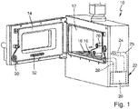
- the device 10 shown for the additive manufacturing of a three-dimensional object from powdered material essentially corresponds to that in FIG figure 1 the EP 3 023 228 A1 shown facility.
- the device 10 comprises an object formation chamber 12 which can be closed with a door 14 .
- a work surface 16 is provided in the chamber 12 and has a construction platform 18 on which the three-dimensional object is produced.
- a coater 20 embodied as a wiper arm is provided in the chamber 12 and is used to sweep powdered material from a storage location onto the construction platform 18 .
- the powdered material is then sintered or melted layer by layer with a laser unit (not shown) in order to finally produce the three-dimensional object.
- a gas flow system 22 is also provided, with which a gas flow is provided over the construction platform 18 .
- gas is sucked out of the chamber 12 at an opening 24 and conducted via a line 25 from the opening 24 to a filter unit 26 .
- the gas flows through the filter unit 26 and is returned to the chamber 12 .
- the filtered gas is first conducted via a line 28 into an opening 30 on the door 14 corresponding to the opening of the line 28 and is conducted into the chamber 12 through inlets 32 on the door side.
- the gas system 22 can contain other components, in particular a pump that generates the gas flow together with the associated regulation and control unit figure 1 are not shown.
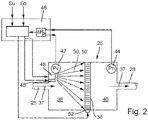
- the figure 2 shows a schematic view of the filter unit 26, with the supply line 25 and the discharge line 28.
- a filter medium 36 is provided in the filter unit 26, through which gas coming from the line 25 flows, the filtered gas leaving the filter unit 26 through the line 28.
- the gas flow or the direction of the gas flow through the filter medium 36 is indicated by the arrows 37 .
- the filter medium 36 consequently divides the filter unit 26 into an upstream space 38 and a downstream space 40.
- a pressure sensor 42 for measuring the Gas pressure p v provided in front of the filter medium 36
- a pressure sensor 44 for measuring the gas pressure p n behind the filter medium 36 is provided in space 40 .
- the output signals of the pressure sensors 42 and 44 are fed to a monitoring device 46, which determines the differential pressure ⁇ p r from the difference between the pressures p n and p v , i.e. the pressures in the space 38 in front of the filter medium 36 and in the space 40 behind the filter medium 36.
- the filter media 36 is arranged vertically; according to the invention, however, it may be advantageous to arrange the filter medium 36 horizontally, so that the inert material can be distributed evenly on the filter medium 36 and cannot slide down from the filter medium as a result of gravity.
- a metering device 48 for metering and applying granular or powdered inert material 50 to the filter medium 36 is also shown schematically.
- the metering device 48 is controlled by the monitoring device 46 .
- the inert material 50 can, for example, by spraying, as in the figure 2 indicated by the dashed arrows, are applied to the filter medium 36 .
- One spray can be sufficient.
- the dosing device 48 can also be designed to additionally apply drying agent 50 ′ to the filter medium 36 .
- the dosing device 48 can be equipped with two feeds, for example.
- drying agent 50′ can also be added directly to the inert material 50 .
- the device 10 a second dosing device 48' for applying the desiccant 50' to the filter medium 36, for example by spraying.
- the applied desiccant (50') removes moisture from the gas flowing through the filter medium 36 anyway, e.g. water, but also other liquids that have evaporated during sintering or melting of the powdery material and have been absorbed by the gas flow.
- a cleaning unit 52 for cleaning the filter medium is also indicated schematically.
- the cleaning unit 52 When the cleaning unit 52 is activated by the monitoring device 46, the inert material 50 is cleaned off together with the particles that collect in the inert material 50. Cleaning can take place, for example, mechanically by brushing or pneumatically by applying a pressure surge to the filter medium 36 against the actual direction of flow.
- the device 10 operates according to the steps as described in figure 3 are shown.
- a first step S 1 the differential pressure ⁇ p 1 between the gas pressure p v1 in front of the filter medium 36 in space 38 and the gas pressure p n1 behind the filter medium 36 in space 40 is determined by means of the pressure sensors 42 , 44 .
- This differential gas pressure ⁇ p 1 is determined when the filter medium 36 is not contaminated, in particular when no object is being produced and when gas flows through the filter medium 36 at operating pressure.
- the monitoring device 46 controls the dosing device 48 in step S 2 so that the granular or powdered inert material 50 is applied to the filter medium 36 .
- the differential pressure ⁇ p 2 i.e. the difference between the gas pressures p V2 upstream of the filter medium 36 in space 38 and the gas pressure p n2 downstream of the filter medium 36 in space 40, is determined in step S 3 , and in particular also when no object is being produced and when gas flows through the filter medium 36 at operating pressure.
- step S 4 the resulting differential pressure ⁇ p r is determined from the difference between the previously determined differential pressures ⁇ p 2 and ⁇ p 1 .
- step S 5 the degree of application of the inert material to the filter medium 26 is then deduced from the resulting differential pressure ⁇ p r .
- a step S 6 it is determined in a step S 6 whether the resulting differential pressure ⁇ pr is compared with a stored lower threshold value S U and with a stored upper threshold value S o .
- the threshold values can be determined once in a calibration process and stored as reference values. If the resulting differential pressure ⁇ p r is in a range between the lower threshold value S U and the upper threshold value S o , a signal can be output that sufficient inert material is on the filter medium has been applied and that there is a sufficient degree of application.
- the operating differential pressure ⁇ p b between the spaces 40 and 38 is monitored with the monitoring device 46, in particular continuously. If the differential operating pressure ⁇ p b rises above a predeterminable, still permissible degree of clogging Z max , the cleaning unit 52 for cleaning the filter medium 36 can be activated by the monitoring device 46 .
- the production process of the three-dimensional object is preferably interrupted or the cleaning takes place when the object has been completely produced.
Landscapes
- Engineering & Computer Science (AREA)
- Chemical & Material Sciences (AREA)
- Materials Engineering (AREA)
- Manufacturing & Machinery (AREA)
- Chemical Kinetics & Catalysis (AREA)
- Automation & Control Theory (AREA)
- Sustainable Development (AREA)
- Analytical Chemistry (AREA)
- Life Sciences & Earth Sciences (AREA)
- Physics & Mathematics (AREA)
- Plasma & Fusion (AREA)
- Health & Medical Sciences (AREA)
- Environmental & Geological Engineering (AREA)
- Toxicology (AREA)
- Powder Metallurgy (AREA)
Description
- Die Erfindung betrifft ein Verfahren zum Betreiben einer Einrichtung zur additiven Herstellung eines dreidimensionalen Objekts, wobei eine Gasströmung über eine Bauplattform, auf der das dreidimensionale Objekt aufgebaut wird, geführt wird und wobei die Gasströmung durch ein Filtermedium geleitet wird. Die Erfindung betrifft auch eine Einrichtung zur additiven Herstellung eines dreidimensionalen Objekts.
- Derartige Einrichtungen zur additiven Herstellung eines dreidimensionalen Objekts aus pulverförmigem Material weisen eine Objektbildungskammer auf, die in der Regel luftdicht verschlossen ist und während der Herstellung des dreidimensionalen Objekts zur Herstellung einer Schutzgasatmosphäre mit Schutzgas gefüllt ist. In der Objektbildungskammer ist eine Arbeitsfläche vorgesehen, die eine Bauplattform zum Herstellen des dreidimensionalen Objekts darauf aufweist. Ferner ist ein Gasströmungssystem zum Bereitstellen einer Gasströmung über der Bauplattform vorgesehen, wodurch Prozessgase und Partikel, wie beispielsweise beim Herstellungsprozess entstehender Schmauch, abgeführt werden. Zur Filterung der Gasströmung ist eine Filtereinheit mit einem Filtermedium vorgesehen.
- Zur additiven Herstellung eines dreidimensionalen Objekts sind sogenannte "Selective Laser Sintering" (SLS) oder "Selective Laser Melting" (SLM) verfahren, also das selektive Lasersintern sowie das selektive Laserschmelzen bekannt. Dazu wird in der Objektbildungskammer das pulverförmige Material, beispielsweise Metall- oder Keramikpulver, mit einer elektromagnetischen Strahlung, insbesondere mit einem Laserlicht, bestrahlt. Hierfür wird auf der Bauplattform der Kammer eine dünne Pulverschicht aufgebracht, die mit dem Laserlicht zur Herstellung des Objekts gesintert oder geschmolzen wird. Die Herstellung des Objekts erfolgt dabei schrittweise; Pulverschichten werden nacheinander aufgebracht und jeweils gesintert oder geschmolzen. Zwischen den Fertigungsschritten wird das pulverförmige Material mit einer Aufbringungseinrichtung, beispielsweise einem Wischer, einer Walze, einer Bürste oder einer Klinge auf die Bauplattform aufgebracht bzw. aufgestrichen.
- Beim Versintern bzw. Verschmelzen des Pulvers entstehen Prozessgase und sonstige Partikel, wie beispielsweise Pulveraggregate oder Schmauch, die das Innere der Objektbildungskammer sowie Schutzgläser der Lasereinrichtung und zugehörige Komponenten oder Optiken verschmutzen können. Falls Laserlicht von den Verschmutzungen absorbiert wird, kann dies zur Ablenkung des Laserlichts und zu Beschädigungen an den Bauteilen führen. Um derartige Beschädigungen zu vermeiden, werden die als Laserlicht führenden und umlenkenden Bauteile regelmäßig gereinigt, was mit nicht unerheblichem Aufwand verbunden ist.
- Aus der
EP 3 023 228 A1 ist bekannt, ein Gasströmungssystem vorzusehen, das eine Gasströmung über der Bauplattform bereitstellt, um Prozessgase und Pulverpartikel aus dem Bereich der Bauplattform abzuführen. Entsprechende Gasströmungssysteme sind aus derEP 2 687 305 A1 , derEP 1 839 781 A1 oder derDE 10 2010 052 206 bekannt. - Ein Verfahren bzw. eine Einrichtung mit Merkmalen des Oberbegriffs der unabhängigen Patentansprüche ist aus der
WO 2016/079494 A2 bekannt. Um einen zu hohen Druckabfall aufgrund eines zugesetzten Filters im Gasströmungssystem zu erkennen, wird dort vorgeschlagen, Gasdrucksensoren vor und hinter der Filtereinrichtung vorzusehen und den Differenzdruck zu messen. Bei zu stark zugesetztem Filterelement wird dieses dann ausgetauscht. Problematisch ist allerdings, dass die Filterelemente mit vergleichsweise feinen Metallpartikeln zugesetzt sind, die brennbar und leicht entzündlich sind. Zur Lösung dieses Problems schlägt dieWO 2016/079494 A2 vor, die Filterelemente zur Vermeidung einer Reaktion mit Sauerstoff luftdicht zu verschießen, wenn die Tür der Objektbildungskammer geöffnet wird. Die luftdicht verschlossenen Filtermedien können dann ausgetauscht und entsorgt werden. - Aus der
KR 101 344 133 B1 - Der Erfindung liegt die Aufgabe zugrunde, ein Verfahren und eine Einrichtung zur additiven Herstellung eines dreidimensionalen Objekts bereitzustellen, mit dem das Filtermedium in der Einrichtung zur additiven Herstellung eines dreidimensionalen Objekts funktionssicher betrieben werden kann. Insbesondere soll verhindert werden, dass es zu einer Entzündung des Filtermediums, bzw. der daran anhaftenden Partikeln kommen kann.
- Diese Aufgabe wird durch ein Verfahren mit den Merkmalen des Patentanspruchs 1 sowie durch eine Einrichtung mit den Merkmalen des Patentanspruchs 10 gelöst.
- Das erfindungsgemäße Verfahren weist nachfolgende Verfahrensschritte auf:
- Bestimmen des Differenzgasdrucks Δp1 zwischen dem Gasdruck (pv1) vor und dem Gasdruck (pn1) hinter dem Filtermedium vor einer Aufbringung von Inertmaterial auf das Filtermedium bei durch das Filtermedium hindurchströmender Gasströmung,
- Aufbringen von Inertmaterial auf das Filtermedium,
- Bestimmen des Differenzgasdrucks Δp2 zwischen dem Gasdruck (pv2) vor und dem Gasdruck (pn2) hinter dem Filtermedium nach der Aufbringung des Inertmaterials auf das Filtermedium bei durch das Filtermedium hindurchströmenden Gasströmung,
- Bestimmen des resultierenden Differenzdrucks Δpr aus der Differenz der Differenzdrücke Δp2 und Δp1, und
- Bestimmen eines Aufbringungsgrades von Inertmaterial auf das Filtermedium aus dem resultierenden Differenzdruck Δpr.
- Mit dem erfindungsgemäßen Verfahren wird folglich Inertmaterial auf das Filtermedium, das zur Filterung der Gasströmung der Einrichtung zur additiven Herstellung eines dreidimensionalen Objekts vorgesehen und eingerichtet ist, aufgebracht. Mit dem Inertmaterial werden die zu filternden Stoffe inertisiert, d.h. sie werden zu reaktionsträgen Stoffen umgewandelt bzw. verhalten sich reaktionsträge. Mit dem in Inertmaterial können die zu filternden, reaktiven Partikel beispielsweise ausreichend verdünnt werden, so dass es zu keiner Kettenreaktion kommen kann, bei der oxidierende und sich dadurch aufheizende Partikel weitere Partikel aufschmelzen oder in Brand setzen. Mit dem erfindungsgemäßen Verfahren kann zudem sichergestellt werden, dass ein ausreichender Aufbringungsgrad des Inertmaterials auf das Filtermedium gegeben ist.
- Durch die Bestimmung des Differenzgasdrucks Δp1 kann folglich der Druckabfall aufgrund des Filtermediums bestimmt werden, und zwar insbesondere ohne dass zu filternde Partikel oder ohne dass Inertmaterial auf dem Filtermedium vorgesehen sind. Der Differenzgasdruck Δp1 wird folglich insbesondere mit einem unbenutzten, also einem frischen Filtermedium durchgeführt. Nach der Bestimmung des Differenzgasdrucks Δp1 wird das Inertmaterial auf das Filtermedium aufgebracht, beispielsweise aufgesprüht oder aufgestrichen. Nach dem Aufbringen von Inertmaterial auf das Filterelement wird der Differenzgasdruck Δp2 erneut bestimmt. Aus dem resultierenden Differenzdruck Δpr kann dann auf den Aufbringungsgrad des Inertmaterials auf das Filterelement, also wieviel Inertmaterial auf dem Filtermedium vorhanden ist bzw. wie stark das Filtermedium mit dem Inertmaterial zugesetzt ist, rückgeschlossen werden. Damit kann sichergestellt werden, das ausreichend Inertmaterial auf dem Filtermedium vorhanden ist, um beim Vorgang der additiven Herstellung des dreidimensionalen Objekts entstehende Partikel am Filtermedium sicher inertisieren zu können.
- Das erfindungsgemäße Verfahren wird insbesondere dann durchgeführt, wenn kein Objekt hergestellt wird. Dadurch können unerwünschte Verunreinigungen des Filtermediums während der Messung der Differenzgasdrücke Δp1 und Δp2 vermieden werden.
- Es ist vorteilhaft, wenn der resultierende Differenzdruck Δpr mit einem hinterlegten unteren Schwellwert SU und/oder mit einem hinterlegten oberen Schwellwert So verglichen wird. Durch einen Vergleich kann bestimmt werden, ob der Aufbringungsgrad von Inertmaterial auf das Filtermedium ausreichend ist. Liegt der resultierende Differenzdruck Δpr unterhalb eines unteren Schwellwerts SU, dann ist eine unzureichende Aufbringung von Inertmaterial auf das Filtermedium erfolgt. Liegt der resultierende Differenzdruck Δpr oberhalb eines oberen Schwellwerts So, so ist davon auszugehen, dass zu viel Inertmaterial auf das Filtermedium aufgebracht wurde.
- Dabei ist vorteilhaft, wenn ein Signal erzeugt und/oder ausgegeben wird, wenn der resultierende Differenzdruck Δpr oberhalb des unteren Schwellwerts SU und/oder unterhalb des oberen Schwellwerts So ist. Durch ein derartiges Signal kann signalisiert werden, dass ausreichend Inertmaterial auf das Filtermedium aufgebracht wurde. Ferner ist denkbar, dass dann ein Signal erzeugt wird, wenn der resultierende Differenzdruck Δpr unterhalb des unteren Schwellwerts SU ist. Mit einem solchen Signal kann signalisiert werden, dass zu wenig Inertmaterial aufgetragen wurde. Schließlich ist auch denkbar, dass dann ein Signal ausgegeben wird, wenn der resultierende Differenzdruck Δpr oberhalb des oberen Schwellwerts ist. Damit kann zum Ausdruck gebracht werden, dass zu viel Inertmaterial auf das Filtermedium aufgebracht wurde.
- Durch die Erzeugung und/oder Ausgabe eines derartigen Signals kann ein Betriebszustand zugelassen oder verhindert werden.
- Gemäß der Erfindung kann weiterhin vorgesehen sein, dass während der Herstellung eines dreidimensionalen Objekts ein Betriebsdifferenzdruck Δpb kontinuierlich und/oder in regelmäßigen oder unregelmäßigen Abständen bestimmt wird, und dass aus dem Betriebsdifferenzdruck Δpb ein Zusetzungsgrad ZF des Filtermediums bestimmt wird. Steigt der Betriebsdifferenzdruck Δpb an, so geht dies mit einem Zusetzen des Filtermediums mit den aus dem Gasstrom herausgefilterten Partikeln einher. Je höher der Betriebsdifferenzdruck Δpb ist, desto mehr Partikel setzen das Filtermedium zu.
- Dabei kann vorgesehen sein, dass bei Überschreiten eines vorgegebenen Zusetzungsgrades Zmax ein Signal erzeugt und/oder ausgegeben wird. Damit kann signalisiert werden, dass der Strömungswiderstand des Filtermediums im Betrieb der Einrichtung zu groß ist, und dass das Filtermedium auszutauschen oder zu reinigen ist.
- In diesem Zusammenhang kann vorgesehen sein, dass bei Überschreiten des vorgegebenen Zusetzungsgrades Zmax der Betriebszustand geändert wird und das Filtermedium abgereinigt wird. Ein Abreinigen kann dabei automatisiert, beispielsweise durch einen Druckluftstoß, eine Rückspülung, ein Abbürsten oder dergleichen erfolgen. Dazu kann eine geeignete Abreinigungseinrichtung vorgesehen sein, die bei Überschreiten des vorgegebenen Zusetzungsgrades Zmax automatisiert angesteuert wird. Das Abreinigen des Filtermediums erfolgt dabei vorzugsweise nicht während der Herstellung des Objekts, sondern während einer Herstellungsunterbrechung oder zwischen zwei Herstellungsvorgängen.
- Dabei kann vorgesehen sein, dass vor Beginn des Herstellungsprozesses ein oder mehrere Sprühstöße von Inertmaterial auf das Filtermedium aufgebracht werden und dass eine Abreinigung des Filtermediums dann erfolgt, wenn der zulässige Zusetzungsgrad Zmax aufgrund eines Zusetzens des Filtermediums durch die reaktiven Partikel, wie Pulver, Schmauch etc. erreicht bzw.überschritten wird.
- Ferner ist auch denkbar, dass zunächst eine erste Dosis von Inertmaterial auf das Filtermedium aufgebracht wird und dass dann im Betrieb das weitere Zusetzen des Filtermediums mit den Partikeln überwacht wird. Bei Erreichen eines ersten Zusetzungsgrades Z1 wird dann eine weitere Dosis von Inertmaterial auf das Filtermedium aufgebracht. Dieser Vorgang kann mehrfach wiederholt werden, bis der maximal zulässige Zusetzungsgrades Zmax erreicht ist. Dies ist insbesondere dann vorteilhaft, wenn das Inertmaterial und die reaktiven Partikel gut aneinander haften.
- Außerdem ist es denkbar zunächst reaktive Partikel auf dem Filtermaterial zu sammeln und anschließend das Inertmaterial aufzubringen. Dies ist ebenfalls insbesondere dann vorteilhaft, wenn das Inertmaterial und die reaktiven Partikel gut aneinander haften.
- Als Inertmaterial findet granulat- oder pulverförmiges Material Verwendung, das Kalk (Kalziumkarbonat), Sand, Glas und/oder Keramik umfasst und/oder daraus gebildet ist.
- Bevorzugt ist das Inertmaterial aus einem Trocknungsmittel gebildet oder umfasst zusätzlich ein Trocknungsmittel. Dies hat den Vorteil, dass die durch das Filtermedium hindurchströmende Gasströmung durch das auf dem Filtermedium aufgebrachte Trocknungsmittel getrocknet wird, wodurch bspw. ein Tausch des mit Flüssigkeiten versetzten Gases gegen trockenes Gas seltener notwendig wird oder die Verwendung einer teuren, zusätzlichen Gasreinigungsanlage vermieden wird. Unter Trocknung der Gasströmung versteht man hierbei das Entfernen von Flüssigkeiten, insbesondere Wasser, aus der Gasströmung. Bekannte Trocknungsmittel binden Flüssigkeiten bspw. durch Adsorption, Absorption oder chemische Reaktionen. Beispiele, insbesondere für Wasser, sind Kieselgel, Zeolithe, Kalziumchlorid, Kalziumoxid und/oder Aluminiumoxid. Besonders bevorzugt werden Trocknungsmittel verwendet, die zumindest im trockenen Zustand bzgl. der am Filtermedium anhaftenden Partikel nicht oxidierend wirken. Dadurch wird der Verbrauch zusätzlichen Inertmaterials zur Inertisierung des Trocknungsmittels vermieden.
- Vorteilhafterweise wird Trocknungsmittel in einem vom Aufbringen von Inertmaterial auf das Filtermedium unabhängigen Schritt auf das Filtermedium aufgebracht. Dadurch ist es möglich unabhängig voneinander einen gerade ausreichenden Aufbringungsgrad an Inertmaterial und Trocknungsmittel auf dem Filtermedium sicherzustellen. Dies ist vorteilhaft, da dadurch eine Überdosierung von Inertmaterial bzw. Trocknungsmittel vermieden wird.
- Zusätzlich können hierbei folgende Schritte durchgeführt werden:
- Bestimmen des Differenzgasdrucks Δp1 zwischen dem Gasdruck (pv1) vor und dem Gasdruck (pn1) hinter dem Filtermedium vor einer Aufbringung von Trocknungsmittel auf das Filtermedium bei durch das Filtermedium hindurchströmender Gasströmung,
- mindestens einmaliges Bestimmen des Differenzgasdrucks Δp2 zwischen dem Gasdruck (pv2) vor und dem Gasdruck (pn2) hinter dem Filtermedium nach der Aufbringung des Trocknungsmittels auf das Filtermedium bei durch das Filtermedium hindurchströmender Gasströmung,
- Bestimmen des resultierenden Differenzdrucks Δpr aus der Differenz der Differenzdrücke Δp2 und Δp1, und
- Bestimmen eines Aufbringungsgrades von Trocknungsmittel auf das Filtermedium und/oder des Aufbringungsgrades von Trocknungsmittel sowie einer durch das Trocknungsmittel gebundenen Flüssigkeitsmenge aus dem resultierenden Differenzdruck Δpr. Dadurch ist es möglich einen ausreichenden Aufbringungsgrad an Inertmaterial und Trocknungsmittel auf dem Filtermedium zu bestimmen, insbesondere durch Bestimmung der durch das Trocknungsmittel gebundenen Flüssigkeitsmenge. So beeinflussen bspw. die oxidierende Wirkung von Trocknungsmittel und gebundene Flüssigkeitsmenge die aufzubringende Menge an Inertmaterial, welche zum funktionssicheren Betrieb der Einrichtung zur additiven Herstellung notwendig ist.
- Die eingangs genannte Aufgabe wird auch gelöst durch eine Einrichtung zur additiven Herstellung eines dreidimensionalen Objekts aus pulverförmigem Material mit den Merkmalen des Patentanspruchs 10, wobei eine Dosiereinrichtung zur Dosierung und Aufbringung eines Inertmaterials auf das Filtermedium vorgesehen ist, und wobei die Überwachungseinrichtung und die Dosiereinrichtung zur Ausführung des erfindungsgemäßen Verfahrens eingerichtet sind.
- Dabei ist es vorteilhaft, wenn das Filtermedium horizontal im Raum angeordnet ist, so dass das Inertmaterial sich gleichmäßig auf dem Filtermedium verteilen und nicht der Schwerkraft folgend vom Filtermedium nach unten abgleiten kann.
- Vorteilhafterweise ist die Dosiereinrichtung zusätzlich zur Dosierung und Aufbringung eines Trocknungsmittels auf das Filtermedium eingerichtet. Alternativ kann eine zweite Dosiereinrichtung zur Dosierung und Aufbringung eines Trocknungsmittels auf das Filtermedium vorgesehen sein, wobei die Überwachungseinrichtung und die zweite Dosiereinrichtung zur Ausführung der oben genannten Verfahren, in denen in einem vom Aufbringen von Inertmaterial auf das Filtermedium unabhängigen Schritt Trocknungsmittel auf das Filtermedium aufgebracht wird, eingerichtet sind.
- Weitere Einzelheiten und vorteilhafte Ausgestaltungen sind der nachfolgenden Beschreibung zu entnehmen, anhand derer ein Ausführungsbeispiel der Erfindung näher beschrieben und erläutert ist.
- Es zeigen:
- Figur 1
- eine schematische perspektivische Ansicht einer erfindungsgemäßen Einrichtung zur additiven Herstellung eines dreidimensionalen Objekts;
- Figur 2
- eine schematische Ansicht der Filtereinheit, der Überwachungseinrichtung und der Dosiereinrichtung der Einrichtung gemäß
Figur 1 ; und - Figur 3
- eine systematische Darstellung der Abfolge von Verfahrensschritten des erfindungsgemäßen Verfahrens.
- Die in der
Figur 1 gezeigte Einrichtung 10 zur additiven Herstellung eines dreidimensionalen Objekts aus pulverförmigem Material entspricht im Wesentlichen der inFigur 1 derEP 3 023 228 A1 gezeigten Einrichtung. Die Einrichtung 10 umfasst eine Objektbildungskammer 12, die mit einer Tür 14 verschließbar ist. In der Kammer 12 ist eine Arbeitsfläche 16 vorgesehen, die eine Bauplattform 18 aufweist, auf der das dreidimensionale Objekt hergestellt wird. In der Kammer 12 ist ein als Wischarm ausgebildeter Beschichter 20 vorgesehen, mit dem pulverförmiges Material von einer Vorratsstelle hin auf die Bauplattform 18 gestrichen wird. Mit einer nicht dargestellten Lasereinheit wird dann das pulverförmige Material Schicht für Schicht gesintert oder aufgeschmolzen, um letztlich das dreidimensionale Objekt herzustellen. - Ferner ist ein Gasströmungssystem 22 vorgesehen, mit dem eine Gasströmung über der Bauplattform 18 bereitgestellt wird. Dazu wird Gas aus der Kammer 12 an einer Öffnung 24 abgesaugt und über eine Leitung 25 von der Öffnung 24 hin zu einer Filtereinheit 26 geleitet. Das Gas durchströmt die Filtereinheit 26 und wird zurück in die Kammer 12 geführt. Bei der in der
Figur 1 gezeigten Ausführungsform wird das gefilterte Gas zunächst über eine Leitung 28 in eine mit der Öffnung der Leitung 28 korrespondierende Öffnung 30 an der Tür 14 geleitet und durch türseitige Einlässe 32 in die Kammer 12 geführt. - Das Gassystem 22 kann neben der Filtereinheit 26 weitere Komponenten enthalten, insbesondere eine die Gasströmung erzeugende Pumpe samt zugehöriger Regel- und Steuereinheit, die in der
Figur 1 nicht gezeigt sind. - Für weitere Einzelheiten der in der
Figur 1 gezeigten Einrichtung 10 wird auf die Beschreibung derEP 3 023 228 A1 verwiesen. - Die
Figur 2 zeigt eine schematische Ansicht der Filtereinheit 26, mit der Zuleitung 25 und der Ableitung 28. In der Filtereinheit 26 ist ein Filtermedium 36 vorgesehen, durch welches aus der Leitung 25 kommendes Gas hindurchströmt, wobei das gefilterte Gas die Filtereinheit 26 durch die Leitung 28 verlässt. Der Gasstrom bzw. die Richtung des Gasstroms durch das Filtermedium 36 ist mit den Pfeilen 37 angedeutet. - Das Filtermedium 36 teilt folglich die Filtereinheit 26 in einen stromaufwärtigen Raum 38 und einen stromabwärtigen Raum 40. Im Raum 38 ist ein Drucksensor 42 zur Messung des Gasdrucks pv vor dem Filtermedium 36 vorgesehen; im Raum 40 ist ein Drucksensor 44 zur Messung des Gasdrucks pn hinter dem Filtermedium 36 vorgesehen. Die Ausgangssignale der Drucksensoren 42 und 44 werden einer Überwachungseinrichtung 46 zugeführt, welche aus der Differenz der Drücke pn und pv, also der Drücke im Raum 38 vor dem Filtermedium 36 und im Raum 40 hinter dem Filtermedium 36, den Differenzdruck Δpr bestimmt.
- In der
Figur 2 ist das Filtermedium 36 vertikal angeordnet; gemäß der Erfindung kann es allerdings vorteilhaft sein, das Filtermedium 36 horizontal anzuordnen, sodass das Inertmaterial sich gleichmäßig auf dem Filtermedium 36 verteilen kann und nicht der Schwerkraft folgend vom Filtermedium nach unten abgleiten kann. - In der
Figur 2 ist ferner eine Dosiereinrichtung 48 zur Dosierung und Aufbringung von granulat- oder pulverförmigem Inertmaterial 50 auf das Filtermedium 36 schematisch dargestellt. Zur Dosierung und Aufbringung des Inertmaterials 50 auf das Filtermedium 36 wird die Dosiereinrichtung 48 von der Überwachungseinrichtung 46 angesteuert. Das Inertmaterial 50 kann dabei beispielsweise durch Aufsprühen, wie es in derFigur 2 durch die gestrichelten Pfeile angedeutet ist, auf das Filtermedium 36 aufgebracht werden. Dabei kann ein Sprühstoß ausreichend sein. - Die Dosiereinrichtung 48 kann auch dazu ausgebildet sein zusätzlich Trocknungsmittel 50' auf das Filtermedium 36 aufzubringen. Dazu kann die Dosiereinrichtung 48 bspw. mit zwei Zuführungen ausgestattet sein. Alternativ kann dem Inertmaterial 50 auch direkt Trocknungsmittel 50' beigesetzt sein. In einer weiteren Alternative kann die Einrichtung 10 eine zweite Dosiereinrichtung 48' zum Aufbringen des Trocknungsmittel 50' auf das Filtermedium 36, z.B. durch Aufsprühen, aufweisen.
- Das aufgebrachte Trocknungsmittel (50') entzieht dem ohnehin durch das Filtermedium 36 hindurchströmenden Gas Feuchtigkeit, z.B. Wasser, aber auch andere Flüssigkeiten, die beim Sintern oder Schmelzen des pulverförmigen Materials verdampft und von dem Gasstrom aufgenommen wurden.
- In der
Figur 2 ist ferner eine Abreinigungseinheit 52 zur Abreinigung des Filtermediums schematisch angedeutet. Bei Ansteuerung der Abreinigungseinheit 52 durch die Überwachungseinrichtung 46 wird das Inertmaterial 50 zusammen mit sich im Inertmaterial 50 sammelnden Partikeln abgereinigt. Eine Abreinigung kann beispielsweise mechanisch durch Abbürsten oder pneumatisch durch Aufbringen eines Druckstoßes auf das Filtermedium 36 entgegen der eigentlichen Strömungsrichtung erfolgen. - Zur Durchführung des erfindungsgemäßen Verfahrens arbeitet die Einrichtung 10 gemäß den Schritten, wie sie in
Figur 3 dargestellt sind. - In einem ersten Schritt S1 wird mittels den Drucksensoren 42, 44 der Differenzdruck Δp1 zwischen dem Gasdruck pv1 vor dem Filtermedium 36 im Raum 38 und dem Gasdruck pn1 hinter dem Filtermedium 36 im Raum 40 bestimmt. Dieser Differenzgasdruck Δp1 wird bei nicht verunreinigtem Filtermedium 36 bestimmt, insbesondere dann, wenn kein Objekt hergestellt wird und wenn Gas mit Betriebsdruck durch das Filtermedium 36 hindurchströmt.
- Nach Bestimmen des Differenzgasdrucks Δp1 steuert in Schritt S2 die Überwachungseinrichtung 46 die Dosiereinrichtung 48 an, so dass das granulat- oder pulverförmige Inertmaterial 50 auf das Filtermedium 36 aufgebracht wird.
- Nachdem das Inertmaterial auf das Filtermedium 36 aufgebracht wurde, wird in Schritt S3 der Differenzdruck Δp2, also die Differenz aus den Gasdrücken pV2 vor dem Filtermedium 36 im Raum 38 und dem Gasdruck pn2 hinter dem Filtermedium 36 im Raum 40 bestimmt, und zwar insbesondere ebenfalls dann, wenn kein Objekt hergestellt wird und wenn Gas mit Betriebsdruck durch das Filtermedium 36 hindurchströmt.
- Im Schritt S4 wird der resultierende Differenzdruck Δpr aus der Differenz der zuvor bestimmten Differenzdrücke Δp2 und Δp1 bestimmt.
- In einem nächsten Schritt S5 wird dann aus dem resultierenden Differenzdruck Δpr auf den Aufbringungsgrad des Inertmaterials auf das Filtermedium 26 rückgeschlossen.
- Zur Bestimmung, ob der Aufbringungsgrad innerhalb vorgegebener Grenzen liegt, wird in einem Schritt S6 bestimmt, ob der resultierende Differenzdruck Δpr mit einem hinterlegten unteren Schwellwert SU und mit einem hinterlegten oberen Schwellwert So verglichen. Die Schwellwerte können einmalig in einem Kalibriervorgang ermittelt werden und als Referenzwerte hinterlegt werden. Liegt der resultierende Differenzdruck Δpr in einem Bereich zwischen dem unteren Schwellwert SU und dem oberen Schwellwert So, so kann ein Signal ausgegeben werden, dass ausreichend Inertmaterial auf das Filtermedium aufgebracht wurde und dass ein ausreichender Aufbringungsgrad vorliegt. Liegt der resultierende Differenzdruck Δpr unterhalb dem unteren Schwellwert SU, so wurde zu wenig Inertmaterial auf das Filtermedium aufgebracht und liegt der resultierende Differenzdruck Δpr oberhalb des oberen Schwellwert So, so wurde zu viel Inertmaterial aufgebracht. In derartigen Fällen kann ein entsprechendes Signal generiert werden.
- Im Betrieb der Einrichtung 10, also während des Herstellens eines dreidimensionalen Objekts aus pulverförmigem Material wird der Betriebsdifferenzdruck Δpb zwischen den Räumen 40 und 38 mit der Überwachungseinrichtung 46 insbesondere kontinuierlich überwacht. Steigt der Betriebsdifferenzdruck Δpb über einen vorgebbaren, noch zulässigen Zusetzungsgrad Zmax, so kann die Abreinigungseinheit 52 zur Abreinigung des Filtermediums 36 von der Überwachungseinrichtung 46 angesteuert werden. Während der Abreinigung des Filtermediums 36 wird vorzugsweise der Herstellungsprozess des dreidimensionalen Objekts unterbrochen bzw. die Abreinigung erfolgt dann, wenn das Objekt fertig hergestellt ist.
Claims (11)
- Verfahren zum Betreiben einer Einrichtung (10) zur additiven Herstellung eines dreidimensionalen Objekts, wobei eine Gasströmung (37) über eine Bauplattform, auf der das dreidimensionale Objekt aufgebaut wird, geführt wird und wobei die Gasströmung (37) durch ein Filtermedium (36) geleitet wird, gekennzeichnet durch folgende Schritte:- Bestimmen des Differenzgasdrucks Δp1 zwischen dem Gasdruck (pv1) vor und dem Gasdruck (pn1) hinter dem Filtermedium vor einer Aufbringung von Inertmaterial(50) auf das Filtermedium (36) bei durch das Filtermedium (36) hindurchströmender Gasströmung (37), wobei als Inertmaterial (50) granulat- oder pulverförmiges Material, das Kalk, Sand, Glas, und/oder Keramik umfasst und/oder daraus gebildet ist, Verwendung findet,- Aufbringen von Inertmaterial (50) auf das Filtermedium (36),- Bestimmen des Differenzgasdrucks Δp2 zwischen dem Gasdruck (pv2) vor und dem Gasdruck (pn2) hinter dem Filtermedium nach der Aufbringung des Inertmaterials auf das Filtermedium (36) bei durch das Filtermedium (36) hindurchströmender Gasströmung (37),- Bestimmen des resultierenden Differenzdrucks Δpr aus der Differenz der Differenzdrücke Δp2 und Δp1, und- Bestimmen eines Aufbringungsgrades von Inertmaterial (50) auf das Filtermedium (36) aus dem resultierenden Differenzdruck Δpr.
- Verfahren nach Anspruch 1, dadurch gekennzeichnet, dass der resultierende Differenzdruck Δpr mit einem hinterlegten unteren Schwellwert SU und/oder mit einem hinterlegten oberen Schwellwert SO verglichen wird.
- Verfahren nach Anspruch 2, dadurch gekennzeichnet, dass ein Signal erzeugt und/oder ausgegeben wird,- wenn der resultierende Differenzdruck Δpr oberhalb des unteren Schwellwert SU und/oder unterhalb des oberen Schwellwerts So liegt, und/oder- wenn der resultierende Differenzdruck Δpr unterhalb des unteren Schwellwerts SU liegt, und/oder- wenn der resultierende Differenzdruck Δpr oberhalb des oberen Schwellwerts So liegt.
- Verfahren nach Anspruch 1, 2 oder 3, dadurch gekennzeichnet, dass während der Herstellung eines dreidimensionalen Objekts ein Betriebsdifferenzdruck Δpb bestimmt wird, und dass aus dem Betriebsdifferenzdruck Δpb ein Zusetzungsgrad ZF des Filtermediums bestimmt wird.
- Verfahren nach Anspruch 4, dadurch gekennzeichnet, dass bei Überschreiten eines vorgegebenen Zusetzungsgrades Zmax ein Signal erzeugt und/oder ausgegeben wird.
- Verfahren nach Anspruch 5, dadurch gekennzeichnet, dass bei Überschreiten eines vorgegebenen Zusetzungsgrades Zmax das Filtermedium abgereinigt wird.
- Verfahren nach einem der vorhergehenden Ansprüche,
dadurch gekennzeichnet, dass das Inertmaterial (50) aus einem Trocknungsmittel gebildet ist oder zusätzlich ein Trocknungsmittel umfasst, insbesondere Kieselgel, Zeolithe, Kalziumchlorid, Kalziumoxid und/oder Aluminiumoxid. - Verfahren nach einem der vorhergehenden Ansprüche,
dadurch gekennzeichnet, dass in einem vom Aufbringen des Inertmaterials (50) auf das Filtermedium (36) unabhängigen Schritt Trocknungsmittel (50') auf das Filtermedium (36) aufgebracht wird. - Verfahren nach Anspruch 8, gekennzeichnet durch folgende Schritte:- Bestimmen des Differenzgasdrucks Δp1 zwischen dem Gasdruck (pv1) vor und dem Gasdruck (pn1) hinter dem Filtermedium vor einer Aufbringung von Trocknungsmittel (50') auf das Filtermedium bei durch das Filtermedium (36) hindurchströmender Gasströmung (37),- mindestens einmaliges Bestimmen des Differenzgasdrucks Δp2 zwischen dem Gasdruck (pv2) vor und dem Gasdruck (pn2) hinter dem Filtermedium nach der Aufbringung des Trocknungsmittels (50') auf das Filtermedium (36) bei durch das Filtermedium (36) hindurchströmender Gasströmung (37),- Bestimmen des resultierenden Differenzdrucks Δpr aus der Differenz der Differenzdrücke Δp2 und Δp1, und- Bestimmen eines Aufbringungsgrades von Trocknungsmittel (50') auf das Filtermedium (36) und/oder des Aufbringungsgrades von Trocknungsmittel (50') und einer durch das Trocknungsmittel aufgenommenen aus dem resultierenden Differenzdruck Δpr.
- Einrichtung (10) zur additiven Herstellung eines dreidimensionalen Objekts aus pulverförmigem Material, mit einer Objektbildungskammer (12),mit einer eine Arbeitsfläche (16) in der Objektbildungskammer (12), wobei die Arbeitsfläche (16) eine Bauplattform (18) zum Herstellen des dreidimensionalen Objekts darauf aufweist,mit einem Gasströmungssystem (22) zum Bereitstellen einer Gasströmung (37) über der Bauplattform (18), mit einer Filtereinheit (26) mit einem Filtermedium (36) zur Filterung der Gasströmung (37), undmit einer Überwachungseinrichtung (46) zur Überwachung der Gasdrücke (pv, pn) vor und hinter dem Filtermedium (36) ,dadurch gekennzeichnet, dass eine Dosiereinrichtung (48) zur Dosierung und Aufbringung eines Inertmaterials (50) auf das Filtermedium (36) vorgesehen ist, wobei die Überwachungseinrichtung (46) und die Dosiereinrichtung (48) zur Ausführung eines Verfahrens nach einem der Ansprüche 1 bis 9 eingerichtet sind.
- Einrichtung nach Anspruch 10, dadurch gekennzeichnet, dass die Dosiereinrichtung (48) zusätzlich zur Dosierung und Aufbringung eines Trocknungsmittels (50) auf das Filtermedium (36) eingerichtet ist oder eine zweite Dosiereinrichtung (48') zur Dosierung und Aufbringung eines Trocknungsmittels (50) auf das Filtermedium (36) vorgesehen ist, wobei die Überwachungseinrichtung (46) und die zweite Dosiereinrichtung (48') zur Ausführung eines Verfahrens nach Anspruch 8 oder 9 eingerichtet sind.
Applications Claiming Priority (2)
| Application Number | Priority Date | Filing Date | Title |
|---|---|---|---|
| DE102018115561.1A DE102018115561A1 (de) | 2018-06-28 | 2018-06-28 | Verfahren zum Betreiben einer Einrichtung zur additiven Herstellung eines dreidimensionalen Objekts und derartige Einrichtung |
| PCT/EP2019/067397 WO2020002633A1 (de) | 2018-06-28 | 2019-06-28 | Verfahren zum betreiben einer einrichtung zur additiven herstellung eines dreidimensionalen objekts und derartige einrichtung |
Publications (2)
| Publication Number | Publication Date |
|---|---|
| EP3814038A1 EP3814038A1 (de) | 2021-05-05 |
| EP3814038B1 true EP3814038B1 (de) | 2022-04-06 |
Family
ID=67314726
Family Applications (1)
| Application Number | Title | Priority Date | Filing Date |
|---|---|---|---|
| EP19740494.0A Active EP3814038B1 (de) | 2018-06-28 | 2019-06-28 | Verfahren zum betreiben einer einrichtung zur additiven herstellung eines dreidimensionalen objekts und derartige einrichtung |
Country Status (3)
| Country | Link |
|---|---|
| EP (1) | EP3814038B1 (de) |
| DE (1) | DE102018115561A1 (de) |
| WO (1) | WO2020002633A1 (de) |
Families Citing this family (3)
| Publication number | Priority date | Publication date | Assignee | Title |
|---|---|---|---|---|
| DE102020116030A1 (de) | 2020-06-17 | 2021-12-23 | Eos Gmbh Electro Optical Systems | Filtereinrichtung für eine additive Fertigungsvorrichtung |
| NL2026035B1 (en) * | 2020-07-09 | 2022-03-15 | Additive Ind Bv | Method and apparatus for manufacturing an object by means of additive manufacturing |
| JP7457674B2 (ja) * | 2021-08-13 | 2024-03-28 | 日本電子株式会社 | 三次元積層造形装置 |
Family Cites Families (10)
| Publication number | Priority date | Publication date | Assignee | Title |
|---|---|---|---|---|
| DE102006014835A1 (de) | 2006-03-30 | 2007-10-04 | Fockele, Matthias, Dr. | Vorrichtung zur Herstellung von Gegenständen durch schichtweises Aufbauen aus pulverförmigem Werkstoff |
| GB0813241D0 (en) | 2008-07-18 | 2008-08-27 | Mcp Tooling Technologies Ltd | Manufacturing apparatus and method |
| DE102010052206B4 (de) | 2010-11-10 | 2015-06-18 | Cl Schutzrechtsverwaltungs Gmbh | Vorrichtung zum Herstellen von dreidimensionalen Objekten |
| KR101344133B1 (ko) * | 2013-06-10 | 2013-12-23 | 이경옥 | 탄산칼슘 자동공급장치 |
| DE102014207160A1 (de) * | 2014-04-15 | 2015-10-15 | Eos Gmbh Electro Optical Systems | Umluftfiltervorrichtung für eine Vorrichtung zum schichtweisen Herstellen eines dreidimensionalen Objekts |
| EP2992986B1 (de) * | 2014-09-03 | 2023-06-07 | SLM Solutions Group AG | Vorrichtung zur Herstellung von 3D-Werkstücken durch schichtweises Aufbauverfahren mit einer Trockenvorrichtung |
| JP2017538038A (ja) | 2014-11-21 | 2017-12-21 | レニショウ パブリック リミテッド カンパニーRenishaw Public Limited Company | 付加製造装置および方法 |
| EP3023228B1 (de) | 2014-11-24 | 2018-08-08 | Trumpf Sisma S.r.l. | Gasstrom in einer generativen Herstellungsvorrichtung |
| DE102016203513A1 (de) * | 2016-03-03 | 2017-09-07 | Bayerische Motoren Werke Aktiengesellschaft | Vorrichtung und Verfahren mit Filterung eines Prozessgases |
| DE102016209184A1 (de) * | 2016-05-26 | 2017-11-30 | Ult Ag | Vorrichtung für eine Separation von Partikel enthaltenden Abgasen |
-
2018
- 2018-06-28 DE DE102018115561.1A patent/DE102018115561A1/de not_active Withdrawn
-
2019
- 2019-06-28 WO PCT/EP2019/067397 patent/WO2020002633A1/de not_active Ceased
- 2019-06-28 EP EP19740494.0A patent/EP3814038B1/de active Active
Also Published As
| Publication number | Publication date |
|---|---|
| EP3814038A1 (de) | 2021-05-05 |
| DE102018115561A1 (de) | 2020-01-02 |
| WO2020002633A1 (de) | 2020-01-02 |
Similar Documents
| Publication | Publication Date | Title |
|---|---|---|
| EP3393807B1 (de) | Vorrichtung und verfahren zum herstellen eines dreidimensionalen objekts | |
| EP3181334B1 (de) | Verfahren und vorrichtung zur herstellung von dreidimensionalen bauteilen mittels überschussmengensensor | |
| DE102014207160A1 (de) | Umluftfiltervorrichtung für eine Vorrichtung zum schichtweisen Herstellen eines dreidimensionalen Objekts | |
| DE102008056938B4 (de) | Entstaubungsanlage mit Luft-Rückführung und Reststaubmessung sowie Steuerungsverfahren hierfür | |
| EP1839781A2 (de) | Vorrichtung zur Herstellung von Gegenständen durch schichtweises Aufbauen aus pulverförmigem Werkstoff | |
| EP3318353B1 (de) | Verfahren zur generativen fertigung eines 3-dimensionalen bauteils | |
| DE10105504A1 (de) | Vorrichtung zur Behandlung von Pulver für eine Vorrichtung zum Herstellen eines dreidimensionalen Objekts, Vorrichtung zum Herstellen eines dreidimensionalen Objekts und Verfahren zum Herstellen eines dreidimensionalen Objekts | |
| EP4263023A1 (de) | Entfernen eines teils einer partikelsammelvorrichtung | |
| EP3579998B1 (de) | Erhöhung der oberflächenqualität | |
| WO2020002633A1 (de) | Verfahren zum betreiben einer einrichtung zur additiven herstellung eines dreidimensionalen objekts und derartige einrichtung | |
| WO2019007647A1 (de) | Verfahren zum abkühlen eines dreidimensionalen bauteils und abkühlvorrichtung | |
| WO2017220744A1 (de) | Pulvertrocknung bei der generativen fertigung | |
| WO2024246115A1 (de) | Pulverfördersystem zum fördern von rohmaterialpulver zu einer anlage zum herstellen eines dreidimensionalen werkstücks | |
| DE102019208689A1 (de) | Vorrichtung zur Verarbeitung von zum Laserschmelzen geeignetem Pulver mit zentralem Schutzgasverteiler und mit Sauerstoffmonitoring | |
| WO2023209107A1 (de) | Filtersystem mit individuell abtrennbaren filterkammern | |
| DE102015222776A1 (de) | Verfahren und Vorrichtung zum schichtweisen Herstellen eines dreidimensionalen Objekts | |
| WO2021094075A1 (de) | Filtervorrichtung, verwendung und verfahren zur trockenfiltration mit siliziumdioxid als filtrationshilfsstoff | |
| EP3815880B1 (de) | Trockener strahlweg | |
| DE102017222335A1 (de) | Staubsammler zum Abscheiden von Metallstaub und Verfahren zum Betreiben eines Staubsammlers | |
| DE102021209590A1 (de) | Vorrichtung und Verfahren zum Herstellen eines Bauteils durch additive Fertigung mittels eines Freiraumverfahren | |
| DE102022113609A1 (de) | Verfahren und System zur Steuerung eines Fertigungsprozesses zur additiven Fertigung eines Bauteils | |
| EP4376982A1 (de) | Kontrollierte oxidation | |
| DE102023114305A1 (de) | Pulverfördersystem zum Fördern von Rohmaterialpulver zu einer Anlage zum Herstellen eines dreidimensionalen Werkstücks | |
| EP4376983A1 (de) | Detektion des oxidationsfortschritts von metallkondensat | |
| EP4615608A1 (de) | Verfahren und vorrichtung zur passivierung von in einer filtervorrichtung auftretenden filterrückständen |
Legal Events
| Date | Code | Title | Description |
|---|---|---|---|
| STAA | Information on the status of an ep patent application or granted ep patent |
Free format text: STATUS: UNKNOWN |
|
| STAA | Information on the status of an ep patent application or granted ep patent |
Free format text: STATUS: THE INTERNATIONAL PUBLICATION HAS BEEN MADE |
|
| PUAI | Public reference made under article 153(3) epc to a published international application that has entered the european phase |
Free format text: ORIGINAL CODE: 0009012 |
|
| STAA | Information on the status of an ep patent application or granted ep patent |
Free format text: STATUS: REQUEST FOR EXAMINATION WAS MADE |
|
| 17P | Request for examination filed |
Effective date: 20201120 |
|
| AK | Designated contracting states |
Kind code of ref document: A1 Designated state(s): AL AT BE BG CH CY CZ DE DK EE ES FI FR GB GR HR HU IE IS IT LI LT LU LV MC MK MT NL NO PL PT RO RS SE SI SK SM TR |
|
| DAV | Request for validation of the european patent (deleted) | ||
| DAX | Request for extension of the european patent (deleted) | ||
| REG | Reference to a national code |
Ref country code: DE Ref legal event code: R079 Ref document number: 502019004005 Country of ref document: DE Free format text: PREVIOUS MAIN CLASS: B22F0003105000 Ipc: B22F0010280000 |
|
| GRAP | Despatch of communication of intention to grant a patent |
Free format text: ORIGINAL CODE: EPIDOSNIGR1 |
|
| STAA | Information on the status of an ep patent application or granted ep patent |
Free format text: STATUS: GRANT OF PATENT IS INTENDED |
|
| RIC1 | Information provided on ipc code assigned before grant |
Ipc: C04B 35/00 20060101ALN20211014BHEP Ipc: B33Y 10/00 20150101ALN20211014BHEP Ipc: B01D 46/44 20060101ALI20211014BHEP Ipc: B01D 46/00 20060101ALI20211014BHEP Ipc: B22F 3/105 20060101ALI20211014BHEP Ipc: B33Y 50/02 20150101ALI20211014BHEP Ipc: B33Y 30/00 20150101ALI20211014BHEP Ipc: B22F 10/85 20210101ALI20211014BHEP Ipc: B22F 10/77 20210101ALI20211014BHEP Ipc: B22F 10/28 20210101AFI20211014BHEP |
|
| INTG | Intention to grant announced |
Effective date: 20211111 |
|
| GRAS | Grant fee paid |
Free format text: ORIGINAL CODE: EPIDOSNIGR3 |
|
| GRAA | (expected) grant |
Free format text: ORIGINAL CODE: 0009210 |
|
| STAA | Information on the status of an ep patent application or granted ep patent |
Free format text: STATUS: THE PATENT HAS BEEN GRANTED |
|
| AK | Designated contracting states |
Kind code of ref document: B1 Designated state(s): AL AT BE BG CH CY CZ DE DK EE ES FI FR GB GR HR HU IE IS IT LI LT LU LV MC MK MT NL NO PL PT RO RS SE SI SK SM TR |
|
| REG | Reference to a national code |
Ref country code: GB Ref legal event code: FG4D Free format text: NOT ENGLISH |
|
| REG | Reference to a national code |
Ref country code: CH Ref legal event code: EP |
|
| REG | Reference to a national code |
Ref country code: AT Ref legal event code: REF Ref document number: 1480839 Country of ref document: AT Kind code of ref document: T Effective date: 20220415 |
|
| REG | Reference to a national code |
Ref country code: DE Ref legal event code: R096 Ref document number: 502019004005 Country of ref document: DE |
|
| REG | Reference to a national code |
Ref country code: IE Ref legal event code: FG4D Free format text: LANGUAGE OF EP DOCUMENT: GERMAN |
|
| REG | Reference to a national code |
Ref country code: LT Ref legal event code: MG9D |
|
| REG | Reference to a national code |
Ref country code: NL Ref legal event code: MP Effective date: 20220406 |
|
| PG25 | Lapsed in a contracting state [announced via postgrant information from national office to epo] |
Ref country code: NL Free format text: LAPSE BECAUSE OF FAILURE TO SUBMIT A TRANSLATION OF THE DESCRIPTION OR TO PAY THE FEE WITHIN THE PRESCRIBED TIME-LIMIT Effective date: 20220406 |
|
| PG25 | Lapsed in a contracting state [announced via postgrant information from national office to epo] |
Ref country code: SE Free format text: LAPSE BECAUSE OF FAILURE TO SUBMIT A TRANSLATION OF THE DESCRIPTION OR TO PAY THE FEE WITHIN THE PRESCRIBED TIME-LIMIT Effective date: 20220406 Ref country code: PT Free format text: LAPSE BECAUSE OF FAILURE TO SUBMIT A TRANSLATION OF THE DESCRIPTION OR TO PAY THE FEE WITHIN THE PRESCRIBED TIME-LIMIT Effective date: 20220808 Ref country code: NO Free format text: LAPSE BECAUSE OF FAILURE TO SUBMIT A TRANSLATION OF THE DESCRIPTION OR TO PAY THE FEE WITHIN THE PRESCRIBED TIME-LIMIT Effective date: 20220706 Ref country code: LT Free format text: LAPSE BECAUSE OF FAILURE TO SUBMIT A TRANSLATION OF THE DESCRIPTION OR TO PAY THE FEE WITHIN THE PRESCRIBED TIME-LIMIT Effective date: 20220406 Ref country code: HR Free format text: LAPSE BECAUSE OF FAILURE TO SUBMIT A TRANSLATION OF THE DESCRIPTION OR TO PAY THE FEE WITHIN THE PRESCRIBED TIME-LIMIT Effective date: 20220406 Ref country code: GR Free format text: LAPSE BECAUSE OF FAILURE TO SUBMIT A TRANSLATION OF THE DESCRIPTION OR TO PAY THE FEE WITHIN THE PRESCRIBED TIME-LIMIT Effective date: 20220707 Ref country code: FI Free format text: LAPSE BECAUSE OF FAILURE TO SUBMIT A TRANSLATION OF THE DESCRIPTION OR TO PAY THE FEE WITHIN THE PRESCRIBED TIME-LIMIT Effective date: 20220406 Ref country code: ES Free format text: LAPSE BECAUSE OF FAILURE TO SUBMIT A TRANSLATION OF THE DESCRIPTION OR TO PAY THE FEE WITHIN THE PRESCRIBED TIME-LIMIT Effective date: 20220406 Ref country code: BG Free format text: LAPSE BECAUSE OF FAILURE TO SUBMIT A TRANSLATION OF THE DESCRIPTION OR TO PAY THE FEE WITHIN THE PRESCRIBED TIME-LIMIT Effective date: 20220706 |
|
| PG25 | Lapsed in a contracting state [announced via postgrant information from national office to epo] |
Ref country code: RS Free format text: LAPSE BECAUSE OF FAILURE TO SUBMIT A TRANSLATION OF THE DESCRIPTION OR TO PAY THE FEE WITHIN THE PRESCRIBED TIME-LIMIT Effective date: 20220406 Ref country code: PL Free format text: LAPSE BECAUSE OF FAILURE TO SUBMIT A TRANSLATION OF THE DESCRIPTION OR TO PAY THE FEE WITHIN THE PRESCRIBED TIME-LIMIT Effective date: 20220406 Ref country code: LV Free format text: LAPSE BECAUSE OF FAILURE TO SUBMIT A TRANSLATION OF THE DESCRIPTION OR TO PAY THE FEE WITHIN THE PRESCRIBED TIME-LIMIT Effective date: 20220406 Ref country code: IS Free format text: LAPSE BECAUSE OF FAILURE TO SUBMIT A TRANSLATION OF THE DESCRIPTION OR TO PAY THE FEE WITHIN THE PRESCRIBED TIME-LIMIT Effective date: 20220806 |
|
| REG | Reference to a national code |
Ref country code: DE Ref legal event code: R097 Ref document number: 502019004005 Country of ref document: DE |
|
| PG25 | Lapsed in a contracting state [announced via postgrant information from national office to epo] |
Ref country code: SM Free format text: LAPSE BECAUSE OF FAILURE TO SUBMIT A TRANSLATION OF THE DESCRIPTION OR TO PAY THE FEE WITHIN THE PRESCRIBED TIME-LIMIT Effective date: 20220406 Ref country code: SK Free format text: LAPSE BECAUSE OF FAILURE TO SUBMIT A TRANSLATION OF THE DESCRIPTION OR TO PAY THE FEE WITHIN THE PRESCRIBED TIME-LIMIT Effective date: 20220406 Ref country code: RO Free format text: LAPSE BECAUSE OF FAILURE TO SUBMIT A TRANSLATION OF THE DESCRIPTION OR TO PAY THE FEE WITHIN THE PRESCRIBED TIME-LIMIT Effective date: 20220406 Ref country code: MC Free format text: LAPSE BECAUSE OF FAILURE TO SUBMIT A TRANSLATION OF THE DESCRIPTION OR TO PAY THE FEE WITHIN THE PRESCRIBED TIME-LIMIT Effective date: 20220406 Ref country code: EE Free format text: LAPSE BECAUSE OF FAILURE TO SUBMIT A TRANSLATION OF THE DESCRIPTION OR TO PAY THE FEE WITHIN THE PRESCRIBED TIME-LIMIT Effective date: 20220406 Ref country code: DK Free format text: LAPSE BECAUSE OF FAILURE TO SUBMIT A TRANSLATION OF THE DESCRIPTION OR TO PAY THE FEE WITHIN THE PRESCRIBED TIME-LIMIT Effective date: 20220406 Ref country code: CZ Free format text: LAPSE BECAUSE OF FAILURE TO SUBMIT A TRANSLATION OF THE DESCRIPTION OR TO PAY THE FEE WITHIN THE PRESCRIBED TIME-LIMIT Effective date: 20220406 |
|
| REG | Reference to a national code |
Ref country code: CH Ref legal event code: PL |
|
| PLBE | No opposition filed within time limit |
Free format text: ORIGINAL CODE: 0009261 |
|
| STAA | Information on the status of an ep patent application or granted ep patent |
Free format text: STATUS: NO OPPOSITION FILED WITHIN TIME LIMIT |
|
| REG | Reference to a national code |
Ref country code: BE Ref legal event code: MM Effective date: 20220630 |
|
| 26N | No opposition filed |
Effective date: 20230110 |
|
| PG25 | Lapsed in a contracting state [announced via postgrant information from national office to epo] |
Ref country code: AL Free format text: LAPSE BECAUSE OF FAILURE TO SUBMIT A TRANSLATION OF THE DESCRIPTION OR TO PAY THE FEE WITHIN THE PRESCRIBED TIME-LIMIT Effective date: 20220406 |
|
| PG25 | Lapsed in a contracting state [announced via postgrant information from national office to epo] |
Ref country code: LU Free format text: LAPSE BECAUSE OF NON-PAYMENT OF DUE FEES Effective date: 20220628 Ref country code: LI Free format text: LAPSE BECAUSE OF NON-PAYMENT OF DUE FEES Effective date: 20220630 Ref country code: IE Free format text: LAPSE BECAUSE OF NON-PAYMENT OF DUE FEES Effective date: 20220628 Ref country code: FR Free format text: LAPSE BECAUSE OF NON-PAYMENT OF DUE FEES Effective date: 20220630 Ref country code: CH Free format text: LAPSE BECAUSE OF NON-PAYMENT OF DUE FEES Effective date: 20220630 |
|
| PG25 | Lapsed in a contracting state [announced via postgrant information from national office to epo] |
Ref country code: SI Free format text: LAPSE BECAUSE OF FAILURE TO SUBMIT A TRANSLATION OF THE DESCRIPTION OR TO PAY THE FEE WITHIN THE PRESCRIBED TIME-LIMIT Effective date: 20220406 Ref country code: BE Free format text: LAPSE BECAUSE OF NON-PAYMENT OF DUE FEES Effective date: 20220630 |
|
| PG25 | Lapsed in a contracting state [announced via postgrant information from national office to epo] |
Ref country code: IT Free format text: LAPSE BECAUSE OF FAILURE TO SUBMIT A TRANSLATION OF THE DESCRIPTION OR TO PAY THE FEE WITHIN THE PRESCRIBED TIME-LIMIT Effective date: 20220406 |
|
| GBPC | Gb: european patent ceased through non-payment of renewal fee |
Effective date: 20230628 |
|
| PG25 | Lapsed in a contracting state [announced via postgrant information from national office to epo] |
Ref country code: MK Free format text: LAPSE BECAUSE OF FAILURE TO SUBMIT A TRANSLATION OF THE DESCRIPTION OR TO PAY THE FEE WITHIN THE PRESCRIBED TIME-LIMIT Effective date: 20220406 Ref country code: CY Free format text: LAPSE BECAUSE OF FAILURE TO SUBMIT A TRANSLATION OF THE DESCRIPTION OR TO PAY THE FEE WITHIN THE PRESCRIBED TIME-LIMIT Effective date: 20220406 Ref country code: GB Free format text: LAPSE BECAUSE OF NON-PAYMENT OF DUE FEES Effective date: 20230628 |
|
| PG25 | Lapsed in a contracting state [announced via postgrant information from national office to epo] |
Ref country code: HU Free format text: LAPSE BECAUSE OF FAILURE TO SUBMIT A TRANSLATION OF THE DESCRIPTION OR TO PAY THE FEE WITHIN THE PRESCRIBED TIME-LIMIT; INVALID AB INITIO Effective date: 20190628 |
|
| REG | Reference to a national code |
Ref country code: DE Ref legal event code: R081 Ref document number: 502019004005 Country of ref document: DE Owner name: TRUMPF LASER- UND SYSTEMTECHNIK SE, DE Free format text: FORMER OWNER: TRUMPF LASER- UND SYSTEMTECHNIK GMBH, 71254 DITZINGEN, DE |
|
| PG25 | Lapsed in a contracting state [announced via postgrant information from national office to epo] |
Ref country code: MT Free format text: LAPSE BECAUSE OF FAILURE TO SUBMIT A TRANSLATION OF THE DESCRIPTION OR TO PAY THE FEE WITHIN THE PRESCRIBED TIME-LIMIT Effective date: 20220406 |
|
| PG25 | Lapsed in a contracting state [announced via postgrant information from national office to epo] |
Ref country code: BG Free format text: LAPSE BECAUSE OF FAILURE TO SUBMIT A TRANSLATION OF THE DESCRIPTION OR TO PAY THE FEE WITHIN THE PRESCRIBED TIME-LIMIT Effective date: 20220406 |
|
| PG25 | Lapsed in a contracting state [announced via postgrant information from national office to epo] |
Ref country code: BG Free format text: LAPSE BECAUSE OF FAILURE TO SUBMIT A TRANSLATION OF THE DESCRIPTION OR TO PAY THE FEE WITHIN THE PRESCRIBED TIME-LIMIT Effective date: 20220406 |
|
| PGFP | Annual fee paid to national office [announced via postgrant information from national office to epo] |
Ref country code: DE Payment date: 20250618 Year of fee payment: 7 |
|
| REG | Reference to a national code |
Ref country code: AT Ref legal event code: MM01 Ref document number: 1480839 Country of ref document: AT Kind code of ref document: T Effective date: 20240628 |
|
| PG25 | Lapsed in a contracting state [announced via postgrant information from national office to epo] |
Ref country code: AT Free format text: LAPSE BECAUSE OF NON-PAYMENT OF DUE FEES Effective date: 20240628 |
|
| REG | Reference to a national code |
Ref country code: DE Ref legal event code: R082 Ref document number: 502019004005 Country of ref document: DE Representative=s name: GLEISS GROSSE SCHRELL UND PARTNER MBB PATENTAN, DE |
|
| PG25 | Lapsed in a contracting state [announced via postgrant information from national office to epo] |
Ref country code: TR Free format text: LAPSE BECAUSE OF FAILURE TO SUBMIT A TRANSLATION OF THE DESCRIPTION OR TO PAY THE FEE WITHIN THE PRESCRIBED TIME-LIMIT Effective date: 20220406 |
|
| PGFP | Annual fee paid to national office [announced via postgrant information from national office to epo] |
Ref country code: AT Payment date: 20260410 Year of fee payment: 5 |