EP3813482B1 - Method and apparatus for performing edt - Google Patents
Method and apparatus for performing edt Download PDFInfo
- Publication number
- EP3813482B1 EP3813482B1 EP20213420.1A EP20213420A EP3813482B1 EP 3813482 B1 EP3813482 B1 EP 3813482B1 EP 20213420 A EP20213420 A EP 20213420A EP 3813482 B1 EP3813482 B1 EP 3813482B1
- Authority
- EP
- European Patent Office
- Prior art keywords
- edt
- message
- rrc connection
- rrc
- data
- Prior art date
- Legal status (The legal status is an assumption and is not a legal conclusion. Google has not performed a legal analysis and makes no representation as to the accuracy of the status listed.)
- Active
Links
- 238000000034 method Methods 0.000 title claims description 100
- 230000005540 biological transmission Effects 0.000 claims description 52
- 230000004044 response Effects 0.000 claims description 29
- 238000004891 communication Methods 0.000 claims description 22
- 230000006870 function Effects 0.000 description 38
- 238000007726 management method Methods 0.000 description 18
- 230000011664 signaling Effects 0.000 description 11
- 238000005457 optimization Methods 0.000 description 8
- 230000008569 process Effects 0.000 description 8
- 238000012546 transfer Methods 0.000 description 7
- 230000006835 compression Effects 0.000 description 4
- 238000007906 compression Methods 0.000 description 4
- 238000010586 diagram Methods 0.000 description 4
- 238000005516 engineering process Methods 0.000 description 4
- 238000013507 mapping Methods 0.000 description 4
- 238000005259 measurement Methods 0.000 description 4
- 238000007689 inspection Methods 0.000 description 3
- 238000012913 prioritisation Methods 0.000 description 3
- 238000013468 resource allocation Methods 0.000 description 3
- 230000006978 adaptation Effects 0.000 description 2
- 238000001914 filtration Methods 0.000 description 2
- 238000012545 processing Methods 0.000 description 2
- 230000007704 transition Effects 0.000 description 2
- 230000001960 triggered effect Effects 0.000 description 2
- 230000004913 activation Effects 0.000 description 1
- 238000013475 authorization Methods 0.000 description 1
- 230000006399 behavior Effects 0.000 description 1
- 230000003139 buffering effect Effects 0.000 description 1
- 230000008859 change Effects 0.000 description 1
- 238000012937 correction Methods 0.000 description 1
- 238000005315 distribution function Methods 0.000 description 1
- 230000009977 dual effect Effects 0.000 description 1
- 230000007774 longterm Effects 0.000 description 1
- 238000010295 mobile communication Methods 0.000 description 1
- 238000011084 recovery Methods 0.000 description 1
- 230000008054 signal transmission Effects 0.000 description 1
- 239000000126 substance Substances 0.000 description 1
- 238000012384 transportation and delivery Methods 0.000 description 1
- CSRZQMIRAZTJOY-UHFFFAOYSA-N trimethylsilyl iodide Substances C[Si](C)(C)I CSRZQMIRAZTJOY-UHFFFAOYSA-N 0.000 description 1
- 238000012795 verification Methods 0.000 description 1
Images


Classifications
-
- H—ELECTRICITY
- H04—ELECTRIC COMMUNICATION TECHNIQUE
- H04W—WIRELESS COMMUNICATION NETWORKS
- H04W52/00—Power management, e.g. TPC [Transmission Power Control], power saving or power classes
- H04W52/02—Power saving arrangements
- H04W52/0209—Power saving arrangements in terminal devices
- H04W52/0225—Power saving arrangements in terminal devices using monitoring of external events, e.g. the presence of a signal
- H04W52/0229—Power saving arrangements in terminal devices using monitoring of external events, e.g. the presence of a signal where the received signal is a wanted signal
-
- H—ELECTRICITY
- H04—ELECTRIC COMMUNICATION TECHNIQUE
- H04W—WIRELESS COMMUNICATION NETWORKS
- H04W76/00—Connection management
- H04W76/20—Manipulation of established connections
- H04W76/27—Transitions between radio resource control [RRC] states
-
- H—ELECTRICITY
- H04—ELECTRIC COMMUNICATION TECHNIQUE
- H04W—WIRELESS COMMUNICATION NETWORKS
- H04W74/00—Wireless channel access, e.g. scheduled or random access
- H04W74/08—Non-scheduled or contention based access, e.g. random access, ALOHA, CSMA [Carrier Sense Multiple Access]
- H04W74/0833—Non-scheduled or contention based access, e.g. random access, ALOHA, CSMA [Carrier Sense Multiple Access] using a random access procedure
-
- H—ELECTRICITY
- H04—ELECTRIC COMMUNICATION TECHNIQUE
- H04W—WIRELESS COMMUNICATION NETWORKS
- H04W76/00—Connection management
- H04W76/10—Connection setup
- H04W76/18—Management of setup rejection or failure
-
- H—ELECTRICITY
- H04—ELECTRIC COMMUNICATION TECHNIQUE
- H04W—WIRELESS COMMUNICATION NETWORKS
- H04W52/00—Power management, e.g. TPC [Transmission Power Control], power saving or power classes
- H04W52/02—Power saving arrangements
- H04W52/0209—Power saving arrangements in terminal devices
- H04W52/0225—Power saving arrangements in terminal devices using monitoring of external events, e.g. the presence of a signal
- H04W52/0235—Power saving arrangements in terminal devices using monitoring of external events, e.g. the presence of a signal where the received signal is a power saving command
-
- Y—GENERAL TAGGING OF NEW TECHNOLOGICAL DEVELOPMENTS; GENERAL TAGGING OF CROSS-SECTIONAL TECHNOLOGIES SPANNING OVER SEVERAL SECTIONS OF THE IPC; TECHNICAL SUBJECTS COVERED BY FORMER USPC CROSS-REFERENCE ART COLLECTIONS [XRACs] AND DIGESTS
- Y02—TECHNOLOGIES OR APPLICATIONS FOR MITIGATION OR ADAPTATION AGAINST CLIMATE CHANGE
- Y02D—CLIMATE CHANGE MITIGATION TECHNOLOGIES IN INFORMATION AND COMMUNICATION TECHNOLOGIES [ICT], I.E. INFORMATION AND COMMUNICATION TECHNOLOGIES AIMING AT THE REDUCTION OF THEIR OWN ENERGY USE
- Y02D30/00—Reducing energy consumption in communication networks
- Y02D30/70—Reducing energy consumption in communication networks in wireless communication networks
Definitions
- the present invention relates to a wireless communication system, and more particularly, to a method for a user equipment (UE) to perform early data transmission (EDT) and an apparatus supporting the same.
- UE user equipment
- EDT early data transmission
- a 5G communication system or pre-5G communication system is referred to as a beyond-4G-network communication system or post-long-term evolution (LTE) system.
- LTE post-long-term evolution
- One or more embodiments provide a method for performing, by a user equipment (UE), early data transmission (EDT) in a wireless communication as set forth in the appended claims.
- UE user equipment
- EDT early data transmission
- UE user equipment
- EDT early data transmission
- the power consumption of the UE can be reduced.
- CDMA code division multiple access
- FDMA frequency division multiple access
- TDMA time division multiple access
- OFDMA orthogonal frequency division multiple access
- SC-FDMA single carrier frequency division multiple access
- the CDMA can be implemented with a radio technology such as universal terrestrial radio access (UTRA) or CDMA-2000.
- UTRA universal terrestrial radio access
- the TDMA can be implemented with a radio technology such as global system for mobile communications (GSM)/general packet ratio service (GPRS)/enhanced data rate for GSM evolution (EDGE).
- GSM global system for mobile communications
- GPRS general packet ratio service
- EDGE enhanced data rate for GSM evolution
- the OFDMA can be implemented with a radio technology such as institute of electrical and electronics engineers (IEEE) 802.11 (Wi-Fi), IEEE 802.16 (WiMAX), IEEE 802.20, evolved UTRA (E-UTRA), etc.
- IEEE 802.16m is evolved from IEEE 802.16e, and provides backward compatibility with a system based on the IEEE 802.16e.
- the UTRA is a part of a universal mobile telecommunication system (UMTS).
- 3rd generation partnership project (3GPP) long term evolution (LTE) is a part of an evolved UMTS (E-UMTS) using the E-UTRA.
- the 3GPP LTE uses the OFDMA in a downlink and uses the SC-FDMA in an uplink.
- LTE-advanced (LTE-A) is an evolution of the LTE.
- 5G communication system is an evolution of the LTE-A.
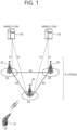
- FIG. 1 shows LTE system architecture.
- the communication network is widely deployed to provide a variety of communication services such as voice over internet protocol (VoIP) through IMS and packet data.
- VoIP voice over internet protocol
- the LTE system architecture includes one or more user equipment (UE; 10), an evolved-UMTS terrestrial radio access network (E-UTRAN) and an evolved packet core (EPC).
- the UE 10 refers to a communication equipment carried by a user.
- the UE 10 may be fixed or mobile, and may be referred to as another terminology, such as a mobile station (MS), a user terminal (UT), a subscriber station (SS), a wireless device, etc.
- MS mobile station
- UT user terminal
- SS subscriber station
- wireless device etc.
- the E-UTRAN includes one or more evolved node-B (eNB) 20, and a plurality of UEs may be located in one cell.
- the eNB 20 provides an end point of a control plane and a user plane to the UE 10.
- the eNB 20 is generally a fixed station that communicates with the UE 10 and may be referred to as another terminology, such as a base station (BS), a base transceiver system (BTS), an access point, etc.
- BS base station
- BTS base transceiver system
- One eNB 20 may be deployed per cell.
- a single cell is configured to have one of bandwidths selected from 1.25, 2.5, 5, 10, and 20 MHz, etc., and provides downlink or uplink transmission services to several UEs. In this case, different cells can be configured to provide different bandwidths.
- a downlink (DL) denotes communication from the eNB 20 to the UE
- an uplink (UL) denotes communication from the UE 10 to the eNB 20.
- a transmitter may be a part of the eNB 20, and a receiver may be a part of the UE 10.
- the transmitter may be a part of the UE 10, and the receiver may be a part of the eNB 20.
- the EPC includes a mobility management entity (MME) which is in charge of control plane functions, and a system architecture evolution (SAE) gateway (S-GW) which is in charge of user plane functions.
- MME mobility management entity
- SAE system architecture evolution gateway
- S-GW system architecture evolution gateway
- the MME/S-GW 30 may be positioned at the end of the network and connected to an external network.
- the MME has UE access information or UE capability information, and such information may be primarily used in UE mobility management.
- the S-GW is a gateway of which an endpoint is an E-UTRAN.
- the MME/S-GW 30 provides an end point of a session and mobility management function for the UE 10.
- the EPC may further include a packet data network (PDN) gateway (PDN-GW).
- PDN-GW is a gateway of which an endpoint is a PDN.
- the MME provides various functions including non-access stratum (NAS) signaling to eNBs 20, NAS signaling security, access stratum (AS) security control, Inter core network (CN) node signaling for mobility between 3GPP access networks, idle mode UE reachability (including control and execution of paging retransmission), tracking area list management (for UE in idle and active mode), P-GW and S-GW selection, MME selection for handovers with MME change, serving GPRS support node (SGSN) selection for handovers to 2G or 3G 3GPP access networks, roaming, authentication, bearer management functions including dedicated bearer establishment, support for public warning system (PWS) (which includes earthquake and tsunami warning system (ETWS) and commercial mobile alert system (CMAS)) message transmission.
- PWS public warning system
- ETWS earthquake and tsunami warning system
- CMAS commercial mobile alert system
- the S-GW host provides assorted functions including per-user based packet filtering (by e.g., deep packet inspection), lawful interception, UE Internet protocol (IP) address allocation, transport level packet marking in the DL, UL and DL service level charging, gating and rate enforcement, DL rate enforcement based on APN-AMBR.
- per-user based packet filtering by e.g., deep packet inspection
- IP Internet protocol
- transport level packet marking in the DL UL and DL service level charging
- gating and rate enforcement DL rate enforcement based on APN-AMBR.
- MME/S-GW 30 will be referred to herein simply as a "gateway,” but it is understood that this entity includes both the MME and S-GW.
- Interfaces for transmitting user traffic or control traffic may be used.
- the UE 10 and the eNB 20 are connected by means of a Uu interface.
- the eNBs 20 are interconnected by means of an X2 interface. Neighboring eNBs may have a meshed network structure that has the X2 interface.
- the eNBs 20 are connected to the EPC by means of an S1 interface.
- the eNBs 20 are connected to the MME by means of an S1-MME interface, and are connected to the S-GW by means of S1-U interface.
- the S1 interface supports a many-to-many relation between the eNB 20 and the MME/S-GW.
- the eNB 20 may perform functions of selection for gateway 30, routing toward the gateway 30 during a radio resource control (RRC) activation, scheduling and transmitting of paging messages, scheduling and transmitting of broadcast channel (BCH) information, dynamic allocation of resources to the UEs 10 in both UL and DL, configuration and provisioning of eNB measurements, radio bearer control, radio admission control (RAC), and connection mobility control in LTE_ACTIVE state.
- RRC radio resource control
- BCH broadcast channel
- gateway 30 may perform functions of paging origination, LTE_IDLE state management, ciphering of the user plane, SAE bearer control, and ciphering and integrity protection of NAS signaling.
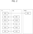
- FIG. 2 shows a control plane of a radio interface protocol of an LTE system.
- FIG. 3 shows a user plane of a radio interface protocol of an LTE system.
- Layers of a radio interface protocol between the UE and the E-UTRAN may be classified into a first layer (L1), a second layer (L2), and a third layer (L3) based on the lower three layers of the open system interconnection (OSI) model that is well-known in the communication system.
- the radio interface protocol between the UE and the E-UTRAN may be horizontally divided into a physical layer, a data link layer, and a network layer, and may be vertically divided into a control plane (C-plane) which is a protocol stack for control signal transmission and a user plane (U-plane) which is a protocol stack for data information transmission.
- C-plane control plane
- U-plane user plane
- the layers of the radio interface protocol exist in pairs at the UE and the E-UTRAN, and are in charge of data transmission of the Uu interface.
- a physical (PHY) layer belongs to the L1.
- the PHY layer provides a higher layer with an information transfer service through a physical channel.
- the PHY layer is connected to a medium access control (MAC) layer, which is a higher layer of the PHY layer, through a transport channel.
- MAC medium access control
- a physical channel is mapped to the transport channel.
- Data is transferred between the MAC layer and the PHY layer through the transport channel.
- the physical channel is modulated using an orthogonal frequency division multiplexing (OFDM) scheme, and utilizes time and frequency as a radio resource.
- OFDM orthogonal frequency division multiplexing
- the PHY layer uses several physical control channels.
- a physical downlink control channel (PDCCH) reports to a UE about resource allocation of a paging channel (PCH) and a downlink shared channel (DL-SCH), and hybrid automatic repeat request (HARQ) information related to the DL-SCH.
- the PDCCH may carry a UL grant for reporting to the UE about resource allocation of UL transmission.
- a physical control format indicator channel (PCFICH) reports the number of OFDM symbols used for PDCCHs to the UE, and is transmitted in every subframe.
- a physical hybrid ARQ indicator channel (PHICH) carries an HARQ acknowledgement (ACK)/non-acknowledgement (NACK) signal in response to UL transmission.
- ACK HARQ acknowledgement
- NACK non-acknowledgement
- a physical uplink control channel (PUCCH) carries UL control information such as HARQ ACK/NACK for DL transmission, scheduling request, and CQI.
- a physical uplink shared channel (PUSCH) carries a UL-uplink shared channel (SCH).
- a physical channel consists of a plurality of subframes in time domain and a plurality of subcarriers in frequency domain.
- One subframe consists of a plurality of symbols in the time domain.
- One subframe consists of a plurality of resource blocks (RBs).
- One RB consists of a plurality of symbols and a plurality of subcarriers.
- each subframe may use specific subcarriers of specific symbols of a corresponding subframe for a PDCCH. For example, a first symbol of the subframe may be used for the PDCCH.
- the PDCCH carries dynamic allocated resources, such as a physical resource block (PRB) and modulation and coding scheme (MCS).
- a transmission time interval (TTI) which is a unit time for data transmission may be equal to a length of one subframe. The length of one subframe may be 1 ms.
- a DL transport channel for transmitting data from the network to the UE includes a broadcast channel (BCH) for transmitting system information, a paging channel (PCH) for transmitting a paging message, a DL-SCH for transmitting user traffic or control signals, etc.
- BCH broadcast channel
- PCH paging channel
- DL-SCH DL-SCH for transmitting user traffic or control signals
- the DL-SCH supports HARQ, dynamic link adaptation by varying the modulation, coding and transmit power, and both dynamic and semi-static resource allocation.
- the DL-SCH also may enable broadcast in the entire cell and the use of beamforming.
- the system information carries one or more system information blocks. All system information blocks may be transmitted with the same periodicity. Traffic or control signals of a multimedia broadcast/multicast service (MBMS) may be transmitted through the DL-SCH or a multicast channel (MCH).
- MCH multicast channel
- a UL transport channel for transmitting data from the UE to the network includes a random access channel (RACH) for transmitting an initial control message, a UL-SCH for transmitting user traffic or control signals, etc.
- RACH random access channel
- the UL-SCH supports HARQ and dynamic link adaptation by varying the transmit power and potentially modulation and coding.
- the UL-SCH also may enable the use of beamforming.
- the RACH is normally used for initial access to a cell.
- a MAC layer belongs to the L2.
- the MAC layer provides services to a radio link control (RLC) layer, which is a higher layer of the MAC layer, via a logical channel.
- RLC radio link control
- the MAC layer provides a function of mapping multiple logical channels to multiple transport channels.
- the MAC layer also provides a function of logical channel multiplexing by mapping multiple logical channels to a single transport channel.
- a MAC sublayer provides data transfer services on logical channels.
- the logical channels are classified into control channels for transferring control plane information and traffic channels for transferring user plane information, according to a type of transmitted information. That is, a set of logical channel types is defined for different data transfer services offered by the MAC layer.
- the logical channels are located above the transport channel, and are mapped to the transport channels.
- the control channels are used for transfer of control plane information only.
- the control channels provided by the MAC layer include a broadcast control channel (BCCH), a paging control channel (PCCH), a common control channel (CCCH), a multicast control channel (MCCH) and a dedicated control channel (DCCH).
- the BCCH is a downlink channel for broadcasting system control information.
- the PCCH is a downlink channel that transfers paging information and is used when the network does not know the location cell of a UE.
- the CCCH is used by UEs having no RRC connection with the network.
- the MCCH is a point-to-multipoint downlink channel used for transmitting MBMS control information from the network to a UE.
- the DCCH is a point-to-point bi-directional channel used by UEs having an RRC connection that transmits dedicated control information between a UE and the network.
- Traffic channels are used for the transfer of user plane information only.
- the traffic channels provided by the MAC layer include a dedicated traffic channel (DTCH) and a multicast traffic channel (MTCH).
- DTCH dedicated traffic channel
- MTCH multicast traffic channel
- the DTCH is a point-to-point channel, dedicated to one UE for the transfer of user information and can exist in both uplink and downlink.
- the MTCH is a point-to-multipoint downlink channel for transmitting traffic data from the network to the UE.
- Uplink connections between logical channels and transport channels include the DCCH that can be mapped to the UL-SCH, the DTCH that can be mapped to the UL-SCH and the CCCH that can be mapped to the UL-SCH.
- Downlink connections between logical channels and transport channels include the BCCH that can be mapped to the BCH or DL-SCH, the PCCH that can be mapped to the PCH, the DCCH that can be mapped to the DL-SCH, and the DTCH that can be mapped to the DL-SCH, the MCCH that can be mapped to the MCH, and the MTCH that can be mapped to the MCH.
- An RLC layer belongs to the L2.
- the RLC layer provides a function of adjusting a size of data, so as to be suitable for a lower layer to transmit the data, by concatenating and segmenting the data received from an upper layer in a radio section.
- QoS quality of service
- the RLC layer provides three operation modes, i.e., a transparent mode (TM), an unacknowledged mode (UM), and an acknowledged mode (AM).
- TM transparent mode
- UM unacknowledged mode
- AM acknowledged mode
- the AM RLC provides a retransmission function through an automatic repeat request (ARQ) for reliable data transmission.
- a function of the RLC layer may be implemented with a functional block inside the MAC layer. In this case, the RLC layer may not exist.
- a packet data convergence protocol (PDCP) layer belongs to the L2.
- the PDCP layer provides a function of header compression function that reduces unnecessary control information such that data being transmitted by employing IP packets, such as IPv4 or IPv6, can be efficiently transmitted over a radio interface that has a relatively small bandwidth.
- the header compression increases transmission efficiency in the radio section by transmitting only necessary information in a header of the data.
- the PDCP layer provides a function of security.
- the function of security includes ciphering which prevents inspection of third parties, and integrity protection which prevents data manipulation of third parties.
- a radio resource control (RRC) layer belongs to the L3.
- the RLC layer is located at the lowest portion of the L3, and is only defined in the control plane.
- the RRC layer takes a role of controlling a radio resource between the UE and the network. For this, the UE and the network exchange an RRC message through the RRC layer.
- the RRC layer controls logical channels, transport channels, and physical channels in relation to the configuration, reconfiguration, and release of RBs.
- An RB is a logical path provided by the L1 and L2 for data delivery between the UE and the network. That is, the RB signifies a service provided the L2 for data transmission between the UE and E-UTRAN.
- the configuration of the RB implies a process for specifying a radio protocol layer and channel properties to provide a particular service and for determining respective detailed parameters and operations.
- the RB is classified into two types, i.e., a signaling RB (SRB) and a data RB (DRB).
- SRB signaling RB
- DRB data RB
- the SRB is used as a path for transmitting an RRC message in the control plane.
- the DRB is used as a path for transmitting user data in the user plane.
- the RLC and MAC layers may perform functions such as scheduling, automatic repeat request (ARQ), and hybrid automatic repeat request (HARQ).
- the RRC layer (terminated in the eNB on the network side) may perform functions such as broadcasting, paging, RRC connection management, RB control, mobility functions, and UE measurement reporting and controlling.
- the NAS control protocol (terminated in the MME of gateway on the network side) may perform functions such as a SAE bearer management, authentication, LTE_IDLE mobility handling, paging origination in LTE_IDLE, and security control for the signaling between the gateway and UE.
- the RLC and MAC layers may perform the same functions for the control plane.
- the PDCP layer may perform the user plane functions such as header compression, integrity protection, and ciphering.
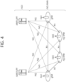
- FIG. 4 shows 5G system architecture.
- a Next Generation Radio Access Network (NG-RAN) node may be either a gNB providing NR Radio Access (NR) user plane and control plane protocol terminations towards the UE or an ng-eNB providing Evolved Universal Terrestrial Radio Access (E-UTRA) user plane and control plane protocol terminations towards the UE.
- NR Radio Access
- E-UTRA Evolved Universal Terrestrial Radio Access
- the gNBs and ng-eNBs may be interconnected with each other by means of the Xn interface.
- the gNBs and ng-eNBs may be also connected by means of the NG interfaces to the 5G Core Network (5GC), more specifically to the AMF (Access and Mobility Management Function) by means of the NG-C interface and to the UPF (User Plane Function) by means of the NG-U interface.
- the NG-C may be control plane interface between NG-RAN and 5GC
- the NG-U may be user plane interface between NG-RAN and 5GC.
- FIG. 5 shows functional split between NG-RAN and 5GC.
- the gNB and ng-eNB may host the following functions:
- the Access and Mobility Management Function may host the following main functions:
- the User Plane Function may host the following main functions:
- the Session Management function may host the following main functions:
- a user equipment performs a random access procedure in the event of one of the following cases.
- a non-contention based random access procedure is provided as follows. First of all, a base station assigns a dedicated random access preamble designated to a specific user equipment. Secondly, the corresponding user equipment performs a random access procedure using the random access preamble. So to speak, in a process for selecting a random access preamble, there are a contention based random access procedure and a non-contention based random access procedure.
- a contention based random access procedure a user equipment randomly selects one random access preamble from a specific set and then uses the selected random access preamble.
- the non-contention based random access procedure a random access preamble assigned by a base station to a specific user equipment only is used.
- the non-contention based random access procedure can be used, as mentioned in the foregoing description, only if a handover process is performed or it is requested by a command given by a base station.
- FIG. 6 shows a contention based random access procedure
- step S610 in a contention based random access procedure, a user equipment randomly selects a random access preamble from a set of random access preambles indicated through a system information or a handover command, selects a PRACH (physical RACH) resource capable of carrying the selected random access preamble, and then transmits the corresponding random access preamble through the selected resource.
- PRACH physical RACH
- step S620 after the user equipment has transmitted the random access preamble in the above manner, it attempts a reception of its random access response within a random access response receiving window indicated through the system information or the handover command from a base station.
- the random access response information is transmitted in format of MAC PDU.
- the MAC PDU is delivered through PDSCH (physical downlink shared channel).
- PDSCH physical downlink shared channel
- PDCCH is delivered as well.
- information on the user equipment supposed to receive the PDSCH, frequency and time information of a radio resource of the PDSCH, a transmission format of the PDSCH and the like are included in the PDCCH.
- the user equipment After the user equipment successfully receives the PDCCH transmitted to itself, the user equipment appropriately receives a random access response transmitted on the PDSCH according to the informations of the PDCCH. And, in the random access response, a random access preamble identifier (ID), a UL grant (UL radio resource), a temporary cell identifier (temporary C-RNTI) and time alignment commands (time synchronization correction values, hereinafter abbreviated TAC) are included.
- ID random access preamble identifier
- UL grant UL radio resource
- temporary C-RNTI temporary cell identifier
- time alignment commands time synchronization correction values
- random access response information for at least one or more user equipments may be included in a single random access response, it is necessary to notify that the UL grant, the temporary C-RNTI and the TAC are valid for which one of the user equipments. And, the random access preamble identifier matches the random access preamble selected by the user equipment in the step S610.
- step S630 if the user equipment receives the random access response valid for itself, the user equipment individually processes each of the information included in the received random access response.
- the user equipment applies the TAC and saves the temporary C-RNTI.
- the user equipment transmits a data saved in its buffer or a newly generated data to the base station using the received UL grant.
- the data included in the UL grant should contain an identifier of the user equipment.
- the base station In the contention based random access procedure, the base station is unable to determine what kinds of user equipments perform the random access procedure. Hence, in order to resolve the contention in the future, the base station should identify the corresponding user equipment.
- the identifier of the user equipment can be included by one of two kinds of methods as follows.
- the user equipment transmits its cell identifier through the UL grant.
- the user equipment fails in receiving the valid cell identifier prior to the random access procedure, the user equipment transmits its unique identifier (e.g., S-TMSI, Random Id, etc.) inclusively. In general, the unique ID is longer than a cell identifier.
- the user equipment initiates a timer for contention resolution (hereinafter called a contention resolution timer).
- step S640 after the user equipment has transmitted the data containing its identifier through the UL grant included in the random access response, it waits for an indication from the base station for the contention resolution. In particular, the user equipment attempts a reception of the PDCCH in order to receive a specific message.
- the user equipment's identifier transmitted through the UL grant is the cell identifier
- the user equipment attempts a reception of the PDCCH using its cell identifier. If the identifier is the unique identifier, the user equipment attempts the reception of the PDCCH using the temporary C-RNTI included in the random access response.
- the user equipment determines that the random access procedure has been normally performed and then ends the random access procedure.
- the user equipment checks data delivered by the PDSCH indicated by the PDCCH. If the unique identifier of the user equipment is included in the substance of the data, the user equipment determines that the random access procedure has been normally performed and then ends the random access procedure.
- FIG. 7 shows a non-contention based random access procedure.
- a random access procedure is ended by determining that the random access procedure has been normally performed.
- the non-contention based random access procedure may exist in one of the two cases, i.e., a first case of a handover process and a second case requested by a command given by a base station.
- a contention based random access procedure can be performed in one of the two cases.
- the random access preamble can be indicated by a handover command or a PDCCH command. After the base station has assigned the random access preamble designated only to the user equipment, the user equipment transmits the preamble to the base station.
- PDU protocol data unit
- a MAC PDU is a bit string that is byte aligned (i.e. multiple of 8 bits) in length.
- MAC SDUs are bit strings that are byte aligned (i.e. multiple of 8 bits) in length.
- a service data unit (SDU) is included into a MAC PDU from the first bit onward.
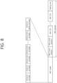
- FIG. 8 shows an example of MAC PDU including MAC header, MAC control elements, MAC SDUs and padding.
- a MAC PDU consists of a MAC header, zero or more MAC SDUs, zero or more MAC control elements, and optionally padding. Both the MAC header and the MAC SDUs are of variable sizes. Both the MAC header and the MAC SDUs are of variable sizes.
- a MAC PDU header consists of one or more MAC PDU subheaders. Each subheader corresponds to either a MAC SDU, a MAC control element or padding.
- a MAC PDU subheader consists of the five or six header fields R/F2/E/LCID/(F)/L but for the last subheader in the MAC PDU and for fixed sized MAC control elements.
- the last subheader in the MAC PDU and subheaders for fixed sized MAC control elements consist solely of the four header fields R/F2/E/LCID.
- a MAC PDU subheader corresponding to padding consists of the four header fields R/F2/E/LCID.
- MAC PDU subheaders have the same order as the corresponding MAC SDUs, MAC control elements and padding. MAC control elements are always placed before any MAC SDU. Padding occurs at the end of the MAC PDU, except when single-byte or two-byte padding is required. Padding may have any value and the MAC entity shall ignore it. When padding is performed at the end of the MAC PDU, zero or more padding bytes are allowed. When single-byte or two-byte padding is required, one or two MAC PDU subheaders corresponding to padding are placed at the beginning of the MAC PDU before any other MAC PDU subheader. A maximum of one MAC PDU can be transmitted per transport block (TB) per MAC entity. A maximum of one MCH MAC PDU can be transmitted per transmission time interval (TTI).
- TTI transmission time interval
- the low cost UE includes Narrow Band Internet of Things (NB-IoT) UE, Bandwidth reduced Low complexity (BL) UE, Machine Type Communication (MTC) UE or a UE in enhanced coverage.
- NB-IoT Narrow Band Internet of Things
- BL Bandwidth reduced Low complexity
- MTC Machine Type Communication
- UE UE in enhanced coverage.
- EDT Early data transmission
- RRC Connection Establishment or RRC Connection Resume is one of the solutions to reduce UE power consumption.
- the current system does not support early data transmission.
- a method for a UE to perform EDT and an apparatus supporting the same according to an embodiment of the present invention are described in detail.
- the EDT may be uplink data transmission during the random access procedure.
- the EDT may allow one uplink data transmission optionally followed by one downlink data transmission during the random access procedure.
- the EDT may allow one uplink data transmission optionally followed by one downlink data transmission during the random access procedure without establishing or resuming the RRC connection.
- S1 connection may be established or resumed upon reception of the uplink data and may be released or suspended after transmission of the downlink data.
- Early data transmission may refer to both control plane (CP)-EDT and user plane (UP)-EDT.
- the UE while performing state transition procedure such as RRC connection establishment procedure or RRC connection resume procedure, the UE may transmit data in a message over signaling radio bearer (SRB) such as DCCH or CCCH.
- SRB signaling radio bearer
- the message may be a NAS message or a RRC message such as RRC Connection Request message or RRC connection resume message.
- RRC connection establishment procedure or RRC connection resume procedure the UE may transmit data in a message over data radio bearer (DRB) configured for EDT.
- DRB data radio bearer
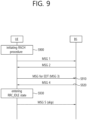
- FIG. 9 shows a procedure for performing EDT according to an embodiment of the present invention.
- the EDT may be triggered when the upper layers have requested the establishment or resumption of the RRC Connection for Mobile Originated data (i.e., not signaling or SMS) and the uplink data size is less than or equal to a transport block (TB) size indicated in the system information.
- the EDT may be not used for data over the control plane when using the User Plane CIoT EPS optimizations.
- the EDT may be applicable to BL UEs, UEs in enhanced coverage or NB-IoT UEs.
- the EDT may be initiated by the upper layers (e.g. UE RRC).
- the UE may initiate a random access procedure.
- the random access procedure may be initiated for the EDT. If the random access procedure is initiated, the UE may transmits message 1 (e.g. random access preamble) to a base station. Then, the UE may receive message 2 (e.g. random access response) from the base station.
- message 1 e.g. random access preamble
- message 2 e.g. random access response
- the UE may be the low cost UE.
- the UE may perform the EDT. Namely, the UE may transmit data to the base station by using message 3 during the random access procedure without establishing or resuming the RRC connection.
- a message transmitted by the UE for performing EDT may be referred to as a first RRC message in the present invention.
- the UE may transmit the first RRC message to the base station in order to perform EDT.
- the first message may include an uplink data for the EDT.
- the first RRC message may be one of a RRC early data request message, a RRC connection request message or a RRC connection resume request message.
- the UE may receive message 4 from the base station.
- the message 4 may be received in response to the first RRC message.
- the message 4 may be referred to as a second RRC message in the present invention.
- the second RRC message may be one of a RRC connection setup message, a RRC connection resume message or a RRC connection reject message.
- the UE may enter RRC_CONNECTED state, and transmit a message 5 to the base station.
- the message 5 may be received in response to the second RRC message.
- the message 5 may be referred to as a third RRC message in the present invention.
- the third RRC message may be one of a RRC connection setup complete message or a RRC connection resume complete message.
- the UE may consider that the EDT ends successfully. That is, the UE may determine that the EDT is ended successfully when the second RRC message indicates that the EDT is successful.
- the UE e.g. UE RRC
- the UE may indicate a release of the RRC connection to upper layers together with the release cause 'other', upon which the procedure ends.
- the UE may enter RRC_lDLE.
- the UE may suspend radio bearer for the EDT before entering the RRC_IDLE state. In this case, the UE may not transmit the third RRC message in response to the second RRC message, to the base station, if the second RRC message indicates that the EDT is successful.
- the UE may consider that the EDT ends unsuccessfully. That is, the UE may determine that the EDT is ended unsuccessfully when the second RRC message indicates that the EDT is not successful. In this case, the UE may suspend radio bearer for the EDT and enter RRC_IDLE. The UE may not transmit the third RRC message in response to the second RRC message, to the base station, if the second RRC message indicates that the EDT is not successful.
- message 5 transmission may be skipped or omitted in certain cases, so that radio resources may not be wasted and battery consumption of the UE may be reduced.
- a RRC connection may be released quickly based on RRC level ACK. If the UE receives a RRC message indicating that the data are acknowledged, the UE may consider that the data are acknowledged in Layer 1, 2 or 3, and the UE may stop (re-)transmissions of any data and RLC/MAC acknowledgements, if any. The UE may release the RRC connection and Layer 2 entities, and enter RRC_IDLE.
- the RRC message may be one of RRC connection release message, a RRC connection reject message, a RRC connection setup message or a RRC connection resume message.
- a RRC complete message may be skipped. If the UE transmits data over SRB or DRB, and if the UE receives a RRC connection setup message or a RRC connection resume message indicating that the data are acknowledged, the UE may not transmit a RRC connection setup complete message or a RRC connection resume complete message). In this case, the UE may consider the RRC procedure successful, and then enter RRC_IDLE.
- the UE may consider that the data are unacknowledged in Layer 1, 2 or 3, and stop (re-)transmissions of any data and RLC/MAC acknowledgements, if any. Then, if the data has been transmitted over DRB (or SRB), the UE may re-establish and suspend Layer 2 entities. If the data has been transmitted over SRB, the UE may release Layer 2 entities. Finally, the UE may enter RRC_IDLE and may trigger the RRC connection establishment or the RRC connection resume procedure for retransmission of the data that was not delivered and unacknowledged in Layer 1, 2 or 3.
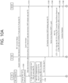
- FIG. 10A and 10B show a procedure for performing EDT according to an embodiment of the present invention.
- the UE may camp on a cell.
- the cell may be a NB-IoT cell or a LTE cell supporting one or more narrowband for low cost UE capabilities such Category M1.
- the UE may receive system information from a base station via the cell.
- the system information may broadcast at least one of configuration of CCCH2 for EDT, configuration of radio bearers (e.g. DRBs including DTCHs) mapped to EDT, RAPID indicating EDT or LCID of CCCH2 for EDT.
- Each cell may inform one or more UEs that this cell supports EDT for the Control Plane CIoT EPS optimization and/or EDT for the User Plane CIoT EPS optimization via system information.
- the UE supporting EDT for User Plane CIoT EPS optimization may configure DRB(s) (including RLC/PDCP entities and logical channels) mapped to EDT.
- the UE may configure one CCCH logical channel and one or more DTCH logical channels for uplink.
- the CCCH logical channel may have a higher priority than the DTCH logical channel(s) mapped to EDT and all MAC Control Elements.
- the DTCH logical channel(s) mapped to EDT may have a higher priority than some or all of MAC Control Element(s) (e.g.
- the Data Volume and Power Headroom Report (DPR) MAC control element may have a higher priority than the DTCH logical channels not mapped to EDT.
- DPR Data Volume and Power Headroom Report
- the UE supporting EDT for Control Plane CIoT EPS optimization may configure CCCH2 for EDT.
- the UE may configure two different CCCH logical channels for uplink.
- the first CCCH logical channel may have a higher priority than the second CCCH logical channel in MAC logical channel prioritization.
- the first CCCH logical channel may be SRB0 while the second CCCH logical channel may be SRB0bis.
- the first CCCH logical channel may be applicable for uplink and downlink, while the second CCCH logical channel may be applicable only for uplink.
- the first CCCH logical channel may have a higher priority than all MAC Control Elements.
- the second CCCH logical channel may have a lower priority than a certain MAC Control Element(s) (e.g. The Data Volume and Power Headroom Report (DPR) MAC control element, Buffer Status Report MAC Control Element, Power Headroom MAC Control Element).
- the second CCCH logical channel may have a higher priority than the other MAC Control Element(s).
- both CCCH logical channels may have a higher priority than all MAC Control Elements.
- the CCCH2 may be replaced by DCCH mapped to EDT or a legacy CCCH.
- DCCH mapped to EDT may be used to carry EDT instead of CCCH2.
- DCCH not mapped to EDT may not be used to carry EDT.
- step S 1020 if the UE has been suspended after release of the previous RRC connection, DTCH(s) mapped to EDT may have been configured but suspended for the UE.
- the UE may resume the DTCH(s) mapped to EDT and then submit the UL data to lower layers (RLC/PDCP entities) over the DTCH mapped to EDT.
- This behavior may not be applied to DTCHs (i.e. DRBs) not mapped to EDT.
- the UE may not perform EDT for UL data over DTCHs (i.e. DRBs) not mapped to EDT.
- the UE may also trigger RRC connection establishment procedure or RRC connection resume procedure.
- the RRC connection request message or the RRC connection resume request message may be submitted to CCCH1 for SRB0.
- step S1030 if a random access procedure is triggered, the MAC layer of the UE (i.e. UE MAC) may select one of random access preamble identifiers (RAPIDs) mapped to EDT (as received from the cell via system information). Then, the UE may transmit a random access preamble with the selected random access preamble identifier (RAPID).
- RAPIDs random access preamble identifiers
- the UE MAC may receive a random access response (RAR) message indicating the transmitted RAPID and an uplink grant. If the UE MAC receives no RAR indicating the transmitted RAPID, the UE MAC re-transmits a random access preamble with power ramping.
- RAR random access response
- the UE MAC may perform logical channel prioritization. Then, the UE MAC may construct MAC PDU based on logical channel priorities and the uplink grant. In the logical channel prioritization, CCCH1 and the DCCHs mapped to EDT may have a higher priority than all MAC Control Elements and the other DCCHs not mapped to EDT.
- LCID indicating CCCH may be included as a MAC sub-header.
- LCID indicating the DCCH mapped to EDT may be included as a MAC sub-header.
- BSR buffer status reporting
- DPR Data Volume and Power Headroom Report
- the UE may include BSR MAC CE indicating the amount of the remaining UL data or DPR MAC CE indicating the amount of the remaining UL data.
- the UE may include BSR MAC CE indicating the amount of the remaining UL data or DPR MAC CE indicating the amount of the remaining UL data.
- the UE MAC may transmit the MAC PDU (i.e. Message 3 (MSG3)) to the base station by using the uplink grant.
- MSG3 Message 3
- step S1060 if the UE MAC may receive contention resolution to the message 3 from the base station (e.g. via PDCCH or Contention Resolution MAC CE), the UE MAC may consider the RACH procedure successful. Otherwise, the UE MAC may re-transmit a random access preamble.
- the base station e.g. via PDCCH or Contention Resolution MAC CE
- the UE may receive RRC connection setup message or RRC connection resume message from the base station. If the received message indicates NACK to EDT, the layer of the UE received the NACK may send the NACK to a higher layer of the UE. For example, for EDT over SRB in Control Plane CIoT EPS optimization, if the UE RRC receives the NACK from the message, the UE RRC may inform UE NAS about the NACK to the UL data. Upon receiving the NACK, the higher layer of the UE (e.g. UE NAS) may re-transmit the UL data. If so, the UE RRC may create a RRC message including the UL data and submit the RRC message to lower layers (e.g.
- the RRC message may be carried over either CCCH2 or DCCH. If the message is carried over DCCH, the message may be a RRC connection setup/resume complete including UL data.
- the UL data may include UL data which is NACKed and/or remaining UL data.
- the UE may transmit a single MAC SDU including RRC connection setup/resume complete including UL data with a MAC CE in a single MAC PDU.
- the MAC CE in the MAC PDU may be either BSR MAC CE indicating the amount of the remaining UL data or DPR MAC CE indicating the amount of the remaining UL data. If there is no remaining UL data except the UL data included in the MAC PDU, the MAC CE may indicate no data.
- the UE may consider that the data are acknowledged in Layer 1, 2 or 3, and the UE may stop (re-)transmissions of any data and RLC/MAC acknowledgements, if any.
- the UE may release the RRC connection and Layer 2 entities, and enter RRC_IDLE.
- the RRC message may be one of RRC connection release, a RRC connection reject message, a RRC connection setup message and a RRC connection resume message.
- the base station may transmit RRC connection release indicating ACK to the UL data.
- the UE may consider that the UL data that were transmitted are acknowledged and enter RRC_IDLE.
- the UE RRC may inform UE RLC/MAC that the UL data that were transmitted are acknowledged and (re-)transmissions should be stopped.
- the UE may consider that the UL data that were transmitted are unacknowledged and enter RRC_IDLE.
- the UE may trigger RRC connection establishment procedure or RRC connection resume procedure to re-transmit unacknowledged data later.
- the UE may not transmit a RRC connection setup complete message (or a RRC connection resume complete message), and consider the RRC procedure successful, and then enter RRC_IDLE.
- the UE may consider that the data are unacknowledged in Layer 1, 2 or 3, and the UE may stop (re-)transmissions of any data and RLC/MAC acknowledgements, if any. Then, if the data has been transmitted over DRB (or SRB), the UE may re-establish and suspend Layer 2 entities. If the data has been transmitted over SRB, the UE may release Layer 2 entities. Finally, the UE may enter RRC_IDLE and may trigger the RRC connection establishment or the RRC connection resume procedure for re-transmission of the data that was not delivered and unacknowledged in Layer 1, 2 or 3.
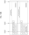
- FIG. 11 is a block diagram illustrating a method for a UE to perform EDT according to an embodiment of the present invention.
- the UE may transmit a first RRC message for the EDT, to a base station.
- the first RRC message may be one of a RRC early data request message, a RRC connection request message or a RRC connection resume request message.
- the UE may be a Narrow Band Internet of Things (NB-IoT) UE.
- the EDT may be performed by a medium access control (MAC) layer of the UE.
- the first message may include an uplink data for the EDT.
- the UE may receive a second RRC message in response to the first RRC message, from the base station.
- the second RRC message may be one of a RRC early data complete message, a RRC connection setup message, a RRC connection resume message or a RRC connection reject message.
- step S1130 the UE may consider that the EDT ends successfully if the second RRC message indicates that the EDT is successful. Namely, the UE may determine that the EDT is ended successfully.
- step S1140 the UE may consider that the EDT ends unsuccessfully if the second RRC message indicates that the EDT is unsuccessful. Namely, the UE may determine that the EDT is ended unsuccessfully.
- the UE does not transmits a third RRC message in response to the second RRC message, to the base station, if the second RRC message indicates that the EDT is successful or unsuccessful.
- the third RRC message may be one of a RRC connection setup complete message or a RRC connection resume complete message.
- the UE may enter RRC_IDLE state. Furthermore, the UE may suspend radio bearer for the EDT before entering the RRC_IDLE state. For example, the UE may suspend all radio bearer for the EDT before entering the RRC_IDLE state.
- the UE may initiate a random access procedure for the EDT.
- the EDT may be an uplink data transmission during the random access procedure.
- the UE may enter a RRC_CONNECTED state and transmit a third RRC message to the base station, if the second RRC message indicates to setup a RRC connection.
- message 5 transmission may be skipped or omitted in certain cases, so that radio resources may not be wasted and battery consumption of the UE may be reduced.
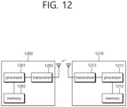
- FIG. 12 is a block diagram illustrating a wireless communication system according to the embodiment of the present invention.
- a BS 1200 includes a processor 1201, a memory 1202 and a transceiver 1203.
- the memory 1202 is connected to the processor 1201, and stores various information for driving the processor 1201.
- the transceiver 1203 is connected to the processor 1201, and transmits and/or receives radio signals.
- the processor 1201 implements proposed functions, processes and/or methods. In the above embodiment, an operation of the base station may be implemented by the processor 1201.
- a UE 1210 includes a processor 1211, a memory 1212 and a transceiver 1213.
- the memory 1212 is connected to the processor 1211, and stores various information for driving the processor 1211.
- the transceiver 1213 is connected to the processor 1211, and transmits and/or receives radio signals.
- the processor 1211 implements proposed functions, processes and/or methods. In the above embodiment, an operation of the user equipment may be implemented by the processor 1211.
- the processor may include an application-specific integrated circuit (ASIC), a separate chipset, a logic circuit, and/or a data processing unit.
- the memory may include a read-only memory (ROM), a random access memory (RAM), a flash memory, a memory card, a storage medium, and/or other equivalent storage devices.
- the transceiver may include a base-band circuit for processing a wireless signal.
- the aforementioned methods can be implemented with a module (i.e., process, function, etc.) for performing the aforementioned functions.
- the module may be stored in the memory and may be performed by the processor.
- the memory may be located inside or outside the processor, and may be coupled to the processor by using various well-known means.
Description
- The present invention relates to a wireless communication system, and more particularly, to a method for a user equipment (UE) to perform early data transmission (EDT) and an apparatus supporting the same.
- In order to meet the demand for wireless data traffic, which has been increasing since the commercialization of a fourth-generation (4G) communication system, efforts are being made to develop an improved fifth-generation (5G) communication system or pre-5G communication system. For this reason, a 5G communication system or pre-5G communication system is referred to as a beyond-4G-network communication system or post-long-term evolution (LTE) system.
The 3GPP Draft No. R2-070543, entitled "Early data transmission", discusses feasibility of early data transmission based on issues raised for early data transmission. The 3GPP Draft No. R1-1708800, entitled "Early data transmission", discusses some aspects of supporting DL/LTL data transmission during the RA procedure for UEs in IDLE mode. - Meanwhile, for low cost UE, it is important to save UE power. Thus, the number of transmissions should be reduced as many as possible. Early data transmission (EDT) in RRC Connection Establishment or RRC Connection Resume is one of the solutions to reduce UE power consumption. However, the current system does not support early data transmission. Thus, a method for a UE to perform EDT and an apparatus supporting the same need to be proposed.
- One or more embodiments provide a method for performing, by a user equipment (UE), early data transmission (EDT) in a wireless communication as set forth in the appended claims.
- Other embodiments provide a user equipment (UE) performing early data transmission (EDT) in a wireless communication as set forth in the appended claims.
- In the following, embodiments and/or examples not falling within the scope of the claims should be understood as mere examples useful for understanding the invention.
- The power consumption of the UE can be reduced.
-
-
FIG. 1 shows LTE system architecture. -
FIG. 2 shows a control plane of a radio interface protocol of an LTE system. -
FIG. 3 shows a user plane of a radio interface protocol of an LTE system. -
FIG. 4 shows 5G system architecture. -
FIG. 5 shows functional split between NG-RAN and 5GC. -
FIG. 6 shows a contention based random access procedure. -
FIG. 7 shows a non-contention based random access procedure. -
FIG. 8 shows an example of MAC PDU including MAC header, MAC control elements, MAC SDUs and padding. -
FIG. 9 shows a procedure for performing EDT according to an embodiment of the present invention. -
FIG. 10A and10B show a procedure for performing EDT according to an embodiment of the present invention. -
FIG. 11 is a block diagram illustrating a method for a UE to perform EDT according to an embodiment of the present invention. -
FIG. 12 is a block diagram illustrating a wireless communication system according to the embodiment of the present invention. - The technology described below can be used in various wireless communication systems such as code division multiple access (CDMA), frequency division multiple access (FDMA), time division multiple access (TDMA), orthogonal frequency division multiple access (OFDMA), single carrier frequency division multiple access (SC-FDMA), etc. The CDMA can be implemented with a radio technology such as universal terrestrial radio access (UTRA) or CDMA-2000. The TDMA can be implemented with a radio technology such as global system for mobile communications (GSM)/general packet ratio service (GPRS)/enhanced data rate for GSM evolution (EDGE). The OFDMA can be implemented with a radio technology such as institute of electrical and electronics engineers (IEEE) 802.11 (Wi-Fi), IEEE 802.16 (WiMAX), IEEE 802.20, evolved UTRA (E-UTRA), etc. IEEE 802.16m is evolved from IEEE 802.16e, and provides backward compatibility with a system based on the IEEE 802.16e. The UTRA is a part of a universal mobile telecommunication system (UMTS). 3rd generation partnership project (3GPP) long term evolution (LTE) is a part of an evolved UMTS (E-UMTS) using the E-UTRA. The 3GPP LTE uses the OFDMA in a downlink and uses the SC-FDMA in an uplink. LTE-advanced (LTE-A) is an evolution of the LTE. 5G communication system is an evolution of the LTE-A.
- For clarity, the following description will focus on LTE-A. However, technical features of the present invention are not limited thereto.
-
FIG. 1 shows LTE system architecture. The communication network is widely deployed to provide a variety of communication services such as voice over internet protocol (VoIP) through IMS and packet data. - Referring to
FIG. 1 , the LTE system architecture includes one or more user equipment (UE; 10), an evolved-UMTS terrestrial radio access network (E-UTRAN) and an evolved packet core (EPC). The UE 10 refers to a communication equipment carried by a user. The UE 10 may be fixed or mobile, and may be referred to as another terminology, such as a mobile station (MS), a user terminal (UT), a subscriber station (SS), a wireless device, etc. - The E-UTRAN includes one or more evolved node-B (eNB) 20, and a plurality of UEs may be located in one cell. The eNB 20 provides an end point of a control plane and a user plane to the UE 10. The eNB 20 is generally a fixed station that communicates with the UE 10 and may be referred to as another terminology, such as a base station (BS), a base transceiver system (BTS), an access point, etc. One eNB 20 may be deployed per cell. There are one or more cells within the coverage of the eNB 20. A single cell is configured to have one of bandwidths selected from 1.25, 2.5, 5, 10, and 20 MHz, etc., and provides downlink or uplink transmission services to several UEs. In this case, different cells can be configured to provide different bandwidths.
- Hereinafter, a downlink (DL) denotes communication from the eNB 20 to the UE 10, and an uplink (UL) denotes communication from the UE 10 to the eNB 20. In the DL, a transmitter may be a part of the eNB 20, and a receiver may be a part of the UE 10. In the UL, the transmitter may be a part of the UE 10, and the receiver may be a part of the eNB 20.
- The EPC includes a mobility management entity (MME) which is in charge of control plane functions, and a system architecture evolution (SAE) gateway (S-GW) which is in charge of user plane functions. The MME/S-
GW 30 may be positioned at the end of the network and connected to an external network. The MME has UE access information or UE capability information, and such information may be primarily used in UE mobility management. The S-GW is a gateway of which an endpoint is an E-UTRAN. The MME/S-GW 30 provides an end point of a session and mobility management function for the UE 10. The EPC may further include a packet data network (PDN) gateway (PDN-GW). The PDN-GW is a gateway of which an endpoint is a PDN. - The MME provides various functions including non-access stratum (NAS) signaling to
eNBs 20, NAS signaling security, access stratum (AS) security control, Inter core network (CN) node signaling for mobility between 3GPP access networks, idle mode UE reachability (including control and execution of paging retransmission), tracking area list management (for UE in idle and active mode), P-GW and S-GW selection, MME selection for handovers with MME change, serving GPRS support node (SGSN) selection for handovers to 2G or 3G 3GPP access networks, roaming, authentication, bearer management functions including dedicated bearer establishment, support for public warning system (PWS) (which includes earthquake and tsunami warning system (ETWS) and commercial mobile alert system (CMAS)) message transmission. The S-GW host provides assorted functions including per-user based packet filtering (by e.g., deep packet inspection), lawful interception, UE Internet protocol (IP) address allocation, transport level packet marking in the DL, UL and DL service level charging, gating and rate enforcement, DL rate enforcement based on APN-AMBR. For clarity MME/S-GW 30 will be referred to herein simply as a "gateway," but it is understood that this entity includes both the MME and S-GW. - Interfaces for transmitting user traffic or control traffic may be used. The
UE 10 and theeNB 20 are connected by means of a Uu interface. TheeNBs 20 are interconnected by means of an X2 interface. Neighboring eNBs may have a meshed network structure that has the X2 interface. TheeNBs 20 are connected to the EPC by means of an S1 interface. TheeNBs 20 are connected to the MME by means of an S1-MME interface, and are connected to the S-GW by means of S1-U interface. The S1 interface supports a many-to-many relation between theeNB 20 and the MME/S-GW. - The
eNB 20 may perform functions of selection forgateway 30, routing toward thegateway 30 during a radio resource control (RRC) activation, scheduling and transmitting of paging messages, scheduling and transmitting of broadcast channel (BCH) information, dynamic allocation of resources to theUEs 10 in both UL and DL, configuration and provisioning of eNB measurements, radio bearer control, radio admission control (RAC), and connection mobility control in LTE_ACTIVE state. In the EPC, and as noted above,gateway 30 may perform functions of paging origination, LTE_IDLE state management, ciphering of the user plane, SAE bearer control, and ciphering and integrity protection of NAS signaling. -
FIG. 2 shows a control plane of a radio interface protocol of an LTE system.FIG. 3 shows a user plane of a radio interface protocol of an LTE system. - Layers of a radio interface protocol between the UE and the E-UTRAN may be classified into a first layer (L1), a second layer (L2), and a third layer (L3) based on the lower three layers of the open system interconnection (OSI) model that is well-known in the communication system. The radio interface protocol between the UE and the E-UTRAN may be horizontally divided into a physical layer, a data link layer, and a network layer, and may be vertically divided into a control plane (C-plane) which is a protocol stack for control signal transmission and a user plane (U-plane) which is a protocol stack for data information transmission. The layers of the radio interface protocol exist in pairs at the UE and the E-UTRAN, and are in charge of data transmission of the Uu interface.
- A physical (PHY) layer belongs to the L1. The PHY layer provides a higher layer with an information transfer service through a physical channel. The PHY layer is connected to a medium access control (MAC) layer, which is a higher layer of the PHY layer, through a transport channel. A physical channel is mapped to the transport channel. Data is transferred between the MAC layer and the PHY layer through the transport channel. Between different PHY layers, i.e., a PHY layer of a transmitter and a PHY layer of a receiver, data is transferred through the physical channel using radio resources. The physical channel is modulated using an orthogonal frequency division multiplexing (OFDM) scheme, and utilizes time and frequency as a radio resource.
- The PHY layer uses several physical control channels. A physical downlink control channel (PDCCH) reports to a UE about resource allocation of a paging channel (PCH) and a downlink shared channel (DL-SCH), and hybrid automatic repeat request (HARQ) information related to the DL-SCH. The PDCCH may carry a UL grant for reporting to the UE about resource allocation of UL transmission. A physical control format indicator channel (PCFICH) reports the number of OFDM symbols used for PDCCHs to the UE, and is transmitted in every subframe. A physical hybrid ARQ indicator channel (PHICH) carries an HARQ acknowledgement (ACK)/non-acknowledgement (NACK) signal in response to UL transmission. A physical uplink control channel (PUCCH) carries UL control information such as HARQ ACK/NACK for DL transmission, scheduling request, and CQI. A physical uplink shared channel (PUSCH) carries a UL-uplink shared channel (SCH).
- A physical channel consists of a plurality of subframes in time domain and a plurality of subcarriers in frequency domain. One subframe consists of a plurality of symbols in the time domain. One subframe consists of a plurality of resource blocks (RBs). One RB consists of a plurality of symbols and a plurality of subcarriers. In addition, each subframe may use specific subcarriers of specific symbols of a corresponding subframe for a PDCCH. For example, a first symbol of the subframe may be used for the PDCCH. The PDCCH carries dynamic allocated resources, such as a physical resource block (PRB) and modulation and coding scheme (MCS). A transmission time interval (TTI) which is a unit time for data transmission may be equal to a length of one subframe. The length of one subframe may be 1 ms.
- The transport channel is classified into a common transport channel and a dedicated transport channel according to whether the channel is shared or not. A DL transport channel for transmitting data from the network to the UE includes a broadcast channel (BCH) for transmitting system information, a paging channel (PCH) for transmitting a paging message, a DL-SCH for transmitting user traffic or control signals, etc. The DL-SCH supports HARQ, dynamic link adaptation by varying the modulation, coding and transmit power, and both dynamic and semi-static resource allocation. The DL-SCH also may enable broadcast in the entire cell and the use of beamforming. The system information carries one or more system information blocks. All system information blocks may be transmitted with the same periodicity. Traffic or control signals of a multimedia broadcast/multicast service (MBMS) may be transmitted through the DL-SCH or a multicast channel (MCH).
- A UL transport channel for transmitting data from the UE to the network includes a random access channel (RACH) for transmitting an initial control message, a UL-SCH for transmitting user traffic or control signals, etc. The UL-SCH supports HARQ and dynamic link adaptation by varying the transmit power and potentially modulation and coding. The UL-SCH also may enable the use of beamforming. The RACH is normally used for initial access to a cell.
- A MAC layer belongs to the L2. The MAC layer provides services to a radio link control (RLC) layer, which is a higher layer of the MAC layer, via a logical channel. The MAC layer provides a function of mapping multiple logical channels to multiple transport channels. The MAC layer also provides a function of logical channel multiplexing by mapping multiple logical channels to a single transport channel. A MAC sublayer provides data transfer services on logical channels.
- The logical channels are classified into control channels for transferring control plane information and traffic channels for transferring user plane information, according to a type of transmitted information. That is, a set of logical channel types is defined for different data transfer services offered by the MAC layer. The logical channels are located above the transport channel, and are mapped to the transport channels.
- The control channels are used for transfer of control plane information only. The control channels provided by the MAC layer include a broadcast control channel (BCCH), a paging control channel (PCCH), a common control channel (CCCH), a multicast control channel (MCCH) and a dedicated control channel (DCCH). The BCCH is a downlink channel for broadcasting system control information. The PCCH is a downlink channel that transfers paging information and is used when the network does not know the location cell of a UE. The CCCH is used by UEs having no RRC connection with the network. The MCCH is a point-to-multipoint downlink channel used for transmitting MBMS control information from the network to a UE. The DCCH is a point-to-point bi-directional channel used by UEs having an RRC connection that transmits dedicated control information between a UE and the network.
- Traffic channels are used for the transfer of user plane information only. The traffic channels provided by the MAC layer include a dedicated traffic channel (DTCH) and a multicast traffic channel (MTCH). The DTCH is a point-to-point channel, dedicated to one UE for the transfer of user information and can exist in both uplink and downlink. The MTCH is a point-to-multipoint downlink channel for transmitting traffic data from the network to the UE.
- Uplink connections between logical channels and transport channels include the DCCH that can be mapped to the UL-SCH, the DTCH that can be mapped to the UL-SCH and the CCCH that can be mapped to the UL-SCH. Downlink connections between logical channels and transport channels include the BCCH that can be mapped to the BCH or DL-SCH, the PCCH that can be mapped to the PCH, the DCCH that can be mapped to the DL-SCH, and the DTCH that can be mapped to the DL-SCH, the MCCH that can be mapped to the MCH, and the MTCH that can be mapped to the MCH.
- An RLC layer belongs to the L2. The RLC layer provides a function of adjusting a size of data, so as to be suitable for a lower layer to transmit the data, by concatenating and segmenting the data received from an upper layer in a radio section. In addition, to ensure a variety of quality of service (QoS) required by a radio bearer (RB), the RLC layer provides three operation modes, i.e., a transparent mode (TM), an unacknowledged mode (UM), and an acknowledged mode (AM). The AM RLC provides a retransmission function through an automatic repeat request (ARQ) for reliable data transmission. Meanwhile, a function of the RLC layer may be implemented with a functional block inside the MAC layer. In this case, the RLC layer may not exist.
- A packet data convergence protocol (PDCP) layer belongs to the L2. The PDCP layer provides a function of header compression function that reduces unnecessary control information such that data being transmitted by employing IP packets, such as IPv4 or IPv6, can be efficiently transmitted over a radio interface that has a relatively small bandwidth. The header compression increases transmission efficiency in the radio section by transmitting only necessary information in a header of the data. In addition, the PDCP layer provides a function of security. The function of security includes ciphering which prevents inspection of third parties, and integrity protection which prevents data manipulation of third parties.
- A radio resource control (RRC) layer belongs to the L3. The RLC layer is located at the lowest portion of the L3, and is only defined in the control plane. The RRC layer takes a role of controlling a radio resource between the UE and the network. For this, the UE and the network exchange an RRC message through the RRC layer. The RRC layer controls logical channels, transport channels, and physical channels in relation to the configuration, reconfiguration, and release of RBs. An RB is a logical path provided by the L1 and L2 for data delivery between the UE and the network. That is, the RB signifies a service provided the L2 for data transmission between the UE and E-UTRAN. The configuration of the RB implies a process for specifying a radio protocol layer and channel properties to provide a particular service and for determining respective detailed parameters and operations. The RB is classified into two types, i.e., a signaling RB (SRB) and a data RB (DRB). The SRB is used as a path for transmitting an RRC message in the control plane. The DRB is used as a path for transmitting user data in the user plane.
- Referring to
FIG. 2 , the RLC and MAC layers (terminated in the eNB on the network side) may perform functions such as scheduling, automatic repeat request (ARQ), and hybrid automatic repeat request (HARQ). The RRC layer (terminated in the eNB on the network side) may perform functions such as broadcasting, paging, RRC connection management, RB control, mobility functions, and UE measurement reporting and controlling. The NAS control protocol (terminated in the MME of gateway on the network side) may perform functions such as a SAE bearer management, authentication, LTE_IDLE mobility handling, paging origination in LTE_IDLE, and security control for the signaling between the gateway and UE. - Referring to
FIG. 3 , the RLC and MAC layers (terminated in the eNB on the network side) may perform the same functions for the control plane. The PDCP layer (terminated in the eNB on the network side) may perform the user plane functions such as header compression, integrity protection, and ciphering. -
FIG. 4 shows 5G system architecture. - Referring to
FIG. 4 , a Next Generation Radio Access Network (NG-RAN) node may be either a gNB providing NR Radio Access (NR) user plane and control plane protocol terminations towards the UE or an ng-eNB providing Evolved Universal Terrestrial Radio Access (E-UTRA) user plane and control plane protocol terminations towards the UE. The gNBs and ng-eNBs may be interconnected with each other by means of the Xn interface. The gNBs and ng-eNBs may be also connected by means of the NG interfaces to the 5G Core Network (5GC), more specifically to the AMF (Access and Mobility Management Function) by means of the NG-C interface and to the UPF (User Plane Function) by means of the NG-U interface. The NG-C may be control plane interface between NG-RAN and 5GC, and the NG-U may be user plane interface between NG-RAN and 5GC. -
FIG. 5 shows functional split between NG-RAN and 5GC. - Referring to
FIG. 5 , the gNB and ng-eNB may host the following functions: - Functions for Radio Resource Management: Radio Bearer Control, Radio Admission Control, Connection Mobility Control, Dynamic allocation of resources to UEs in both uplink and downlink (scheduling);
- IP header compression, encryption and integrity protection of data;
- Selection of an AMF at UE attachment when no routing to an AMF can be determined from the information provided by the UE;
- Routing of User Plane data towards UPF(s);
- Routing of Control Plane information towards AMF;
- Connection setup and release;
- Scheduling and transmission of paging messages;
- Scheduling and transmission of system broadcast information (originated from the AMF or O&M);
- Measurement and measurement reporting configuration for mobility and scheduling;
- Transport level packet marking in the uplink;
- Session Management;
- Support of Network Slicing;
- QoS Flow management and mapping to data radio bearers;
- Support of UEs in RRC_INACTIVE state;
- Distribution function for NAS messages;
- Radio access network sharing;
- Dual Connectivity;
- Tight interworking between NR and E-UTRA.
- The Access and Mobility Management Function (AMF) may host the following main functions:
- NAS signalling termination;
- NAS signalling security;
- AS Security control;
- Inter CN node signalling for mobility between 3GPP access networks;
- Idle mode UE Reachability (including control and execution of paging retransmission);
- Registration Area management;
- Support of intra-system and inter-system mobility;
- Access Authentication;
- Access Authorization including check of roaming rights;
- Mobility management control (subscription and policies);
- Support of Network Slicing;
- SMF selection.
- The User Plane Function (UPF) may host the following main functions:
- Anchor point for Intra-/Inter-RAT mobility (when applicable);
- External PDU session point of interconnect to Data Network;
- Packet routing & forwarding;
- Packet inspection and User plane part of Policy rule enforcement;
- Traffic usage reporting;
- Uplink classifier to support routing traffic flows to a data network;
- Branching point to support multi-homed PDU session;
- QoS handling for user plane, e.g. packet filtering, gating, UL/DL rate enforcement;
- Uplink Traffic verification (SDF to QoS flow mapping);
- Downlink packet buffering and downlink data notification triggering.
- The Session Management function (SMF) may host the following main functions:
- Session Management;
- UE IP address allocation and management;
- Selection and control of UP function;
- Configures traffic steering at UPF to route traffic to proper destination;
- Control part of policy enforcement and QoS;
- Downlink Data Notification.
- Hereinafter, a random access procedure in LTE system is described.
- First of all, a user equipment performs a random access procedure in the event of one of the following cases.
- Case that a user equipment performs an initial access without a connection (e.g., RRC connection) to a base station
- Case that a user equipment initially accesses a target cell by a handover procedure
- Case requested by a command given by a base station
- Case that data in uplink is generated in a situation that an uplink time synchronization is not matched or a radio resource used to request a radio resource is not allocated
- Case of a recovery process in case of a radio link failure (RLF) or a handover failure
- In LTE system, a non-contention based random access procedure is provided as follows. First of all, a base station assigns a dedicated random access preamble designated to a specific user equipment. Secondly, the corresponding user equipment performs a random access procedure using the random access preamble. So to speak, in a process for selecting a random access preamble, there are a contention based random access procedure and a non-contention based random access procedure. In particular, according to the contention based random access procedure, a user equipment randomly selects one random access preamble from a specific set and then uses the selected random access preamble. According to the non-contention based random access procedure, a random access preamble assigned by a base station to a specific user equipment only is used. Differences between the two kinds of the random access procedures lie in a presence or non-presence of occurrence of a contention problem. The non-contention based random access procedure can be used, as mentioned in the foregoing description, only if a handover process is performed or it is requested by a command given by a base station.
-
FIG. 6 shows a contention based random access procedure. - In step S610, in a contention based random access procedure, a user equipment randomly selects a random access preamble from a set of random access preambles indicated through a system information or a handover command, selects a PRACH (physical RACH) resource capable of carrying the selected random access preamble, and then transmits the corresponding random access preamble through the selected resource.
- In step S620, after the user equipment has transmitted the random access preamble in the above manner, it attempts a reception of its random access response within a random access response receiving window indicated through the system information or the handover command from a base station. In particular, the random access response information is transmitted in format of MAC PDU. And, the MAC PDU is delivered through PDSCH (physical downlink shared channel). In order for the user equipment to appropriately receive the information delivered through the PDSCH, PDCCH is delivered as well. In particular, information on the user equipment supposed to receive the PDSCH, frequency and time information of a radio resource of the PDSCH, a transmission format of the PDSCH and the like are included in the PDCCH. Once the user equipment successfully receives the PDCCH transmitted to itself, the user equipment appropriately receives a random access response transmitted on the PDSCH according to the informations of the PDCCH. And, in the random access response, a random access preamble identifier (ID), a UL grant (UL radio resource), a temporary cell identifier (temporary C-RNTI) and time alignment commands (time synchronization correction values, hereinafter abbreviated TAC) are included. As mentioned in the above description, the random access preamble identifier is required for the random access response. The reason for this is described as follows. First of all, since random access response information for at least one or more user equipments may be included in a single random access response, it is necessary to notify that the UL grant, the temporary C-RNTI and the TAC are valid for which one of the user equipments. And, the random access preamble identifier matches the random access preamble selected by the user equipment in the step S610.
- In step S630, if the user equipment receives the random access response valid for itself, the user equipment individually processes each of the information included in the received random access response. In particular, the user equipment applies the TAC and saves the temporary C-RNTI. Moreover, the user equipment transmits a data saved in its buffer or a newly generated data to the base station using the received UL grant. In this case, the data included in the UL grant should contain an identifier of the user equipment. In the contention based random access procedure, the base station is unable to determine what kinds of user equipments perform the random access procedure. Hence, in order to resolve the contention in the future, the base station should identify the corresponding user equipment. The identifier of the user equipment can be included by one of two kinds of methods as follows. First of all, if the user equipment has a valid cell identifier previously assigned by a corresponding cell prior to the random access procedure, the user equipment transmits its cell identifier through the UL grant. On the contrary, if the user equipment fails in receiving the valid cell identifier prior to the random access procedure, the user equipment transmits its unique identifier (e.g., S-TMSI, Random Id, etc.) inclusively. In general, the unique ID is longer than a cell identifier. If the user equipment transmits the data through the UL grant, the user equipment initiates a timer for contention resolution (hereinafter called a contention resolution timer).
- In step S640, after the user equipment has transmitted the data containing its identifier through the UL grant included in the random access response, it waits for an indication from the base station for the contention resolution. In particular, the user equipment attempts a reception of the PDCCH in order to receive a specific message. In receiving the PDCCH, there are two kinds of methods. As mentioned in the foregoing description, if the user equipment's identifier transmitted through the UL grant is the cell identifier, the user equipment attempts a reception of the PDCCH using its cell identifier. If the identifier is the unique identifier, the user equipment attempts the reception of the PDCCH using the temporary C-RNTI included in the random access response. Thereafter, in the former case, if the user equipment receives the PDCCH through its cell identifier before the expiration of the contention resolution timer, the user equipment determines that the random access procedure has been normally performed and then ends the random access procedure. In the latter case, if the user equipment receives the PDCCH through the temporary cell identifier before the expiration of the contention resolution timer, the user equipment checks data delivered by the PDSCH indicated by the PDCCH. If the unique identifier of the user equipment is included in the substance of the data, the user equipment determines that the random access procedure has been normally performed and then ends the random access procedure.
-
FIG. 7 shows a non-contention based random access procedure. - Unlike the contention based random access procedure, in a non-contention based random access procedure, if a random access response information is received, a random access procedure is ended by determining that the random access procedure has been normally performed. The non-contention based random access procedure may exist in one of the two cases, i.e., a first case of a handover process and a second case requested by a command given by a base station. Of course, a contention based random access procedure can be performed in one of the two cases. First of all, for a non-contention based random access procedure, it is important to receive a designated random access preamble having no possibility in contention from a base station. The random access preamble can be indicated by a handover command or a PDCCH command. After the base station has assigned the random access preamble designated only to the user equipment, the user equipment transmits the preamble to the base station.
- Hereinafter, a protocol data unit (PDU) is described.
- A MAC PDU is a bit string that is byte aligned (i.e. multiple of 8 bits) in length. MAC SDUs are bit strings that are byte aligned (i.e. multiple of 8 bits) in length. A service data unit (SDU) is included into a MAC PDU from the first bit onward.
-
FIG. 8 shows an example of MAC PDU including MAC header, MAC control elements, MAC SDUs and padding. - Referring to
FIG. 8 , a MAC PDU consists of a MAC header, zero or more MAC SDUs, zero or more MAC control elements, and optionally padding. Both the MAC header and the MAC SDUs are of variable sizes. Both the MAC header and the MAC SDUs are of variable sizes. A MAC PDU header consists of one or more MAC PDU subheaders. Each subheader corresponds to either a MAC SDU, a MAC control element or padding. A MAC PDU subheader consists of the five or six header fields R/F2/E/LCID/(F)/L but for the last subheader in the MAC PDU and for fixed sized MAC control elements. The last subheader in the MAC PDU and subheaders for fixed sized MAC control elements consist solely of the four header fields R/F2/E/LCID. A MAC PDU subheader corresponding to padding consists of the four header fields R/F2/E/LCID. - MAC PDU subheaders have the same order as the corresponding MAC SDUs, MAC control elements and padding. MAC control elements are always placed before any MAC SDU. Padding occurs at the end of the MAC PDU, except when single-byte or two-byte padding is required. Padding may have any value and the MAC entity shall ignore it. When padding is performed at the end of the MAC PDU, zero or more padding bytes are allowed. When single-byte or two-byte padding is required, one or two MAC PDU subheaders corresponding to padding are placed at the beginning of the MAC PDU before any other MAC PDU subheader. A maximum of one MAC PDU can be transmitted per transport block (TB) per MAC entity. A maximum of one MCH MAC PDU can be transmitted per transmission time interval (TTI).
- Meanwhile, for low cost UE, it is important to save UE power. For example, the low cost UE includes Narrow Band Internet of Things (NB-IoT) UE, Bandwidth reduced Low complexity (BL) UE, Machine Type Communication (MTC) UE or a UE in enhanced coverage. Thus, the number of transmissions should be reduced as many as possible. Early data transmission (EDT) in RRC Connection Establishment or RRC Connection Resume is one of the solutions to reduce UE power consumption. However, the current system does not support early data transmission. Hereinafter, a method for a UE to perform EDT and an apparatus supporting the same according to an embodiment of the present invention are described in detail. In the specification, the EDT may be uplink data transmission during the random access procedure. The EDT may allow one uplink data transmission optionally followed by one downlink data transmission during the random access procedure. For example, the EDT may allow one uplink data transmission optionally followed by one downlink data transmission during the random access procedure without establishing or resuming the RRC connection. S1 connection may be established or resumed upon reception of the uplink data and may be released or suspended after transmission of the downlink data. Early data transmission may refer to both control plane (CP)-EDT and user plane (UP)-EDT.
- According to an embodiment of the present invention, while performing state transition procedure such as RRC connection establishment procedure or RRC connection resume procedure, the UE may transmit data in a message over signaling radio bearer (SRB) such as DCCH or CCCH. The message may be a NAS message or a RRC message such as RRC Connection Request message or RRC connection resume message. Alternatively, while performing state transition procedure such as RRC connection establishment procedure or RRC connection resume procedure, the UE may transmit data in a message over data radio bearer (DRB) configured for EDT.
-
FIG. 9 shows a procedure for performing EDT according to an embodiment of the present invention. - The EDT may be triggered when the upper layers have requested the establishment or resumption of the RRC Connection for Mobile Originated data (i.e., not signaling or SMS) and the uplink data size is less than or equal to a transport block (TB) size indicated in the system information. The EDT may be not used for data over the control plane when using the User Plane CIoT EPS optimizations. The EDT may be applicable to BL UEs, UEs in enhanced coverage or NB-IoT UEs. The EDT may be initiated by the upper layers (e.g. UE RRC).
- Referring to
FIG. 9 , in step S900, the UE may initiate a random access procedure. The random access procedure may be initiated for the EDT. If the random access procedure is initiated, the UE may transmits message 1 (e.g. random access preamble) to a base station. Then, the UE may receive message 2 (e.g. random access response) from the base station. The UE may be the low cost UE. - In step S910, the UE may perform the EDT. Namely, the UE may transmit data to the base station by using
message 3 during the random access procedure without establishing or resuming the RRC connection. A message transmitted by the UE for performing EDT may be referred to as a first RRC message in the present invention. The UE may transmit the first RRC message to the base station in order to perform EDT. The first message may include an uplink data for the EDT. For example, the first RRC message may be one of a RRC early data request message, a RRC connection request message or a RRC connection resume request message. - In step S920, the UE may receive
message 4 from the base station. Themessage 4 may be received in response to the first RRC message. Themessage 4 may be referred to as a second RRC message in the present invention. For example, the second RRC message may be one of a RRC connection setup message, a RRC connection resume message or a RRC connection reject message. - If the second RRC message indicates to setup a RRC connection, the UE may enter RRC_CONNECTED state, and transmit a
message 5 to the base station. Themessage 5 may be received in response to the second RRC message. Themessage 5 may be referred to as a third RRC message in the present invention. For example, the third RRC message may be one of a RRC connection setup complete message or a RRC connection resume complete message. - If the second RRC message indicates that the EDT is successful, the UE may consider that the EDT ends successfully. That is, the UE may determine that the EDT is ended successfully when the second RRC message indicates that the EDT is successful. In other word, if the UE receives the second RRC message used to confirm successful completion of the EDT procedure, the UE (e.g. UE RRC) may indicate a release of the RRC connection to upper layers together with the release cause 'other', upon which the procedure ends. Thus, the UE may enter RRC_lDLE. Desirably, the UE may suspend radio bearer for the EDT before entering the RRC_IDLE state. In this case, the UE may not transmit the third RRC message in response to the second RRC message, to the base station, if the second RRC message indicates that the EDT is successful.
- If the second RRC message indicates that the EDT is unsuccessful, the UE may consider that the EDT ends unsuccessfully. That is, the UE may determine that the EDT is ended unsuccessfully when the second RRC message indicates that the EDT is not successful. In this case, the UE may suspend radio bearer for the EDT and enter RRC_IDLE. The UE may not transmit the third RRC message in response to the second RRC message, to the base station, if the second RRC message indicates that the EDT is not successful.
- In case of performing EDT, regardless of whether the EDT has been successfully or not, it may be unnecessary to send
message 5 in response tomessage 4, since the UE may not need to enter the RRC_CONNECTED state in certain cases. According to an embodiment of the present invention, when the UE performs EDT,message 5 transmission may be skipped or omitted in certain cases, so that radio resources may not be wasted and battery consumption of the UE may be reduced. - According to an embodiment of the present invention, a RRC connection may be released quickly based on RRC level ACK. If the UE receives a RRC message indicating that the data are acknowledged, the UE may consider that the data are acknowledged in
Layer Layer 2 entities, and enter RRC_IDLE. The RRC message may be one of RRC connection release message, a RRC connection reject message, a RRC connection setup message or a RRC connection resume message. - According to an embodiment of the present invention, a RRC complete message may be skipped. If the UE transmits data over SRB or DRB, and if the UE receives a RRC connection setup message or a RRC connection resume message indicating that the data are acknowledged, the UE may not transmit a RRC connection setup complete message or a RRC connection resume complete message). In this case, the UE may consider the RRC procedure successful, and then enter RRC_IDLE.
- According to an embodiment of the present invention, in case of connection failure for the EDT, if the UE transmits data over SRB or DRB, and if the RRC connection establishment or the RRC connection resume procedure with EDT fails e.g. due to reception of the RRC connection reject or T300 expiry, the UE may consider that the data are unacknowledged in
Layer Layer 2 entities. If the data has been transmitted over SRB, the UE may releaseLayer 2 entities. Finally, the UE may enter RRC_IDLE and may trigger the RRC connection establishment or the RRC connection resume procedure for retransmission of the data that was not delivered and unacknowledged inLayer -
FIG. 10A and10B show a procedure for performing EDT according to an embodiment of the present invention. - Referring to
FIG. 10A and10B , in step S1000, the UE may camp on a cell. For example, the cell may be a NB-IoT cell or a LTE cell supporting one or more narrowband for low cost UE capabilities such Category M1. - In step S1010, the UE may receive system information from a base station via the cell. The system information may broadcast at least one of configuration of CCCH2 for EDT, configuration of radio bearers (e.g. DRBs including DTCHs) mapped to EDT, RAPID indicating EDT or LCID of CCCH2 for EDT. Each cell may inform one or more UEs that this cell supports EDT for the Control Plane CIoT EPS optimization and/or EDT for the User Plane CIoT EPS optimization via system information.
- If the cell indicates EDT for the User Plane CIoT EPS optimization, the UE supporting EDT for User Plane CIoT EPS optimization may configure DRB(s) (including RLC/PDCP entities and logical channels) mapped to EDT. In this case, the UE may configure one CCCH logical channel and one or more DTCH logical channels for uplink. The CCCH logical channel may have a higher priority than the DTCH logical channel(s) mapped to EDT and all MAC Control Elements. The DTCH logical channel(s) mapped to EDT may have a higher priority than some or all of MAC Control Element(s) (e.g. The Data Volume and Power Headroom Report (DPR) MAC control element, Buffer Status Report MAC Control Element, Power Headroom MAC Control Element). The DTCH logical channel(s) mapped to EDT may have a higher priority than the DTCH logical channels not mapped to EDT.
- If the cell indicates EDT for the Control Plane CIoT EPS optimization, the UE supporting EDT for Control Plane CIoT EPS optimization may configure CCCH2 for EDT. In this case, the UE may configure two different CCCH logical channels for uplink. The first CCCH logical channel may have a higher priority than the second CCCH logical channel in MAC logical channel prioritization. The first CCCH logical channel may be SRB0 while the second CCCH logical channel may be SRB0bis. The first CCCH logical channel may be applicable for uplink and downlink, while the second CCCH logical channel may be applicable only for uplink. The first CCCH logical channel may have a higher priority than all MAC Control Elements. The second CCCH logical channel may have a lower priority than a certain MAC Control Element(s) (e.g. The Data Volume and Power Headroom Report (DPR) MAC control element, Buffer Status Report MAC Control Element, Power Headroom MAC Control Element). The second CCCH logical channel may have a higher priority than the other MAC Control Element(s). Alternatively, both CCCH logical channels may have a higher priority than all MAC Control Elements.
- The CCCH2 may be replaced by DCCH mapped to EDT or a legacy CCCH. For example, DCCH mapped to EDT may be used to carry EDT instead of CCCH2. However, DCCH not mapped to EDT may not be used to carry EDT.
- If the cell does not indicate EDT, UE does not perform EDT.
- In
step S 1020, if the UE has been suspended after release of the previous RRC connection, DTCH(s) mapped to EDT may have been configured but suspended for the UE. In this case, if UE detects UL data for the DTCH(s), the UE may resume the DTCH(s) mapped to EDT and then submit the UL data to lower layers (RLC/PDCP entities) over the DTCH mapped to EDT. This behavior may not be applied to DTCHs (i.e. DRBs) not mapped to EDT. Thus, the UE may not perform EDT for UL data over DTCHs (i.e. DRBs) not mapped to EDT. If the UE detects UL data, the UE may also trigger RRC connection establishment procedure or RRC connection resume procedure. The RRC connection request message or the RRC connection resume request message may be submitted to CCCH1 for SRB0. - In step S1030, if a random access procedure is triggered, the MAC layer of the UE (i.e. UE MAC) may select one of random access preamble identifiers (RAPIDs) mapped to EDT (as received from the cell via system information). Then, the UE may transmit a random access preamble with the selected random access preamble identifier (RAPID).
- In step S1040, the UE MAC may receive a random access response (RAR) message indicating the transmitted RAPID and an uplink grant. If the UE MAC receives no RAR indicating the transmitted RAPID, the UE MAC re-transmits a random access preamble with power ramping.
- The UE MAC may perform logical channel prioritization. Then, the UE MAC may construct MAC PDU based on logical channel priorities and the uplink grant. In the logical channel prioritization, CCCH1 and the DCCHs mapped to EDT may have a higher priority than all MAC Control Elements and the other DCCHs not mapped to EDT.
- In the MAC PDU, if data from CCCH is included, LCID indicating CCCH may be included as a MAC sub-header. In addition, if data from the DCCH mapped to EDT is included, LCID indicating the DCCH mapped to EDT may be included as a MAC sub-header.
- If the received UL grant can accommodate all UL data in the DCCH mapped to EDT, and if the UE has no remaining UL data over any logical channel, the UE may include buffer status reporting (BSR) MAC Control Element indicating no data, Data Volume and Power Headroom Report (DPR) MAC Control Element indicating no data (i.e. DV value=0), or no MAC Control Element.
- If the received UL grant can accommodate some UL data in the DCCH mapped to EDT with a MAC Control Element such as BSR MAC CE or DPR MAC CE, and if the UE has remaining UL data over any logical channel, the UE may include BSR MAC CE indicating the amount of the remaining UL data or DPR MAC CE indicating the amount of the remaining UL data.
- If the received UL grant cannot accommodate any UL data in the DCCH mapped to EDT with a MAC Control Element such as BSR MAC CE or DPR MAC CE, the UE may include BSR MAC CE indicating the amount of the remaining UL data or DPR MAC CE indicating the amount of the remaining UL data.
- In step S1050, the UE MAC may transmit the MAC PDU (i.e. Message 3 (MSG3)) to the base station by using the uplink grant.
- In step S1060, if the UE MAC may receive contention resolution to the
message 3 from the base station (e.g. via PDCCH or Contention Resolution MAC CE), the UE MAC may consider the RACH procedure successful. Otherwise, the UE MAC may re-transmit a random access preamble. - The UE may receive RRC connection setup message or RRC connection resume message from the base station. If the received message indicates NACK to EDT, the layer of the UE received the NACK may send the NACK to a higher layer of the UE. For example, for EDT over SRB in Control Plane CIoT EPS optimization, if the UE RRC receives the NACK from the message, the UE RRC may inform UE NAS about the NACK to the UL data. Upon receiving the NACK, the higher layer of the UE (e.g. UE NAS) may re-transmit the UL data. If so, the UE RRC may create a RRC message including the UL data and submit the RRC message to lower layers (e.g. PDCP/RLC/MAC). The RRC message may be carried over either CCCH2 or DCCH. If the message is carried over DCCH, the message may be a RRC connection setup/resume complete including UL data. The UL data may include UL data which is NACKed and/or remaining UL data. Thus, the UE may transmit a single MAC SDU including RRC connection setup/resume complete including UL data with a MAC CE in a single MAC PDU. The MAC CE in the MAC PDU may be either BSR MAC CE indicating the amount of the remaining UL data or DPR MAC CE indicating the amount of the remaining UL data. If there is no remaining UL data except the UL data included in the MAC PDU, the MAC CE may indicate no data.
- If the UE receives a RRC message indicating that the data are acknowledged, the UE may consider that the data are acknowledged in
Layer Layer 2 entities, and enter RRC_IDLE. The RRC message may be one of RRC connection release, a RRC connection reject message, a RRC connection setup message and a RRC connection resume message. - For example, if the MAC CE indicates no data, and if the base station successfully receives all UL data, in case there is no DL data, the base station may transmit RRC connection release indicating ACK to the UL data. Upon receiving the RRC connection release indicating ACK to the UL data, the UE may consider that the UL data that were transmitted are acknowledged and enter RRC_IDLE. The UE RRC may inform UE RLC/MAC that the UL data that were transmitted are acknowledged and (re-)transmissions should be stopped.
- If the UE receives RRC connection release or reject message not indicating ACK to the UL data, the UE may consider that the UL data that were transmitted are unacknowledged and enter RRC_IDLE. The UE may trigger RRC connection establishment procedure or RRC connection resume procedure to re-transmit unacknowledged data later.
- If the UE transmits data over SRB or DRB, and if the UE receives a RRC connection setup message (or a RRC connection resume message) indicating that the data are acknowledged, the UE may not transmit a RRC connection setup complete message (or a RRC connection resume complete message), and consider the RRC procedure successful, and then enter RRC_IDLE.
- If the UE transmits data over SRB or DRB, and if the RRC connection establishment or the RRC connection resume procedure with EDT fails, e.g. the procedure unsuccessfully ends due to reception of the RRC connection reject or T300 expiry, the UE may consider that the data are unacknowledged in
Layer Layer 2 entities. If the data has been transmitted over SRB, the UE may releaseLayer 2 entities. Finally, the UE may enter RRC_IDLE and may trigger the RRC connection establishment or the RRC connection resume procedure for re-transmission of the data that was not delivered and unacknowledged inLayer -
FIG. 11 is a block diagram illustrating a method for a UE to perform EDT according to an embodiment of the present invention. - Referring to
FIG. 11 , in step S1110, the UE may transmit a first RRC message for the EDT, to a base station. The first RRC message may be one of a RRC early data request message, a RRC connection request message or a RRC connection resume request message. The UE may be a Narrow Band Internet of Things (NB-IoT) UE. The EDT may be performed by a medium access control (MAC) layer of the UE. The first message may include an uplink data for the EDT. - In step S1120, the UE may receive a second RRC message in response to the first RRC message, from the base station. The second RRC message may be one of a RRC early data complete message, a RRC connection setup message, a RRC connection resume message or a RRC connection reject message.
- In step S1130, the UE may consider that the EDT ends successfully if the second RRC message indicates that the EDT is successful. Namely, the UE may determine that the EDT is ended successfully.
- In step S1140, the UE may consider that the EDT ends unsuccessfully if the second RRC message indicates that the EDT is unsuccessful. Namely, the UE may determine that the EDT is ended unsuccessfully.
- The UE does not transmits a third RRC message in response to the second RRC message, to the base station, if the second RRC message indicates that the EDT is successful or unsuccessful. The third RRC message may be one of a RRC connection setup complete message or a RRC connection resume complete message.
- In step S1150, the UE may enter RRC_IDLE state. Furthermore, the UE may suspend radio bearer for the EDT before entering the RRC_IDLE state. For example, the UE may suspend all radio bearer for the EDT before entering the RRC_IDLE state.
- Furthermore, the UE may initiate a random access procedure for the EDT. The EDT may be an uplink data transmission during the random access procedure.
- Furthermore, the UE may enter a RRC_CONNECTED state and transmit a third RRC message to the base station, if the second RRC message indicates to setup a RRC connection.
- According to an embodiment of the present invention, when the UE performs EDT,
message 5 transmission may be skipped or omitted in certain cases, so that radio resources may not be wasted and battery consumption of the UE may be reduced. -
FIG. 12 is a block diagram illustrating a wireless communication system according to the embodiment of the present invention. - A
BS 1200 includes aprocessor 1201, amemory 1202 and atransceiver 1203. Thememory 1202 is connected to theprocessor 1201, and stores various information for driving theprocessor 1201. Thetransceiver 1203 is connected to theprocessor 1201, and transmits and/or receives radio signals. Theprocessor 1201 implements proposed functions, processes and/or methods. In the above embodiment, an operation of the base station may be implemented by theprocessor 1201. - A
UE 1210 includes aprocessor 1211, amemory 1212 and atransceiver 1213. Thememory 1212 is connected to theprocessor 1211, and stores various information for driving theprocessor 1211. Thetransceiver 1213 is connected to theprocessor 1211, and transmits and/or receives radio signals. Theprocessor 1211 implements proposed functions, processes and/or methods. In the above embodiment, an operation of the user equipment may be implemented by theprocessor 1211. - The processor may include an application-specific integrated circuit (ASIC), a separate chipset, a logic circuit, and/or a data processing unit. The memory may include a read-only memory (ROM), a random access memory (RAM), a flash memory, a memory card, a storage medium, and/or other equivalent storage devices. The transceiver may include a base-band circuit for processing a wireless signal. When the embodiment is implemented in software, the aforementioned methods can be implemented with a module (i.e., process, function, etc.) for performing the aforementioned functions. The module may be stored in the memory and may be performed by the processor. The memory may be located inside or outside the processor, and may be coupled to the processor by using various well-known means.
- Various methods based on the present specification have been described by referring to drawings and reference numerals given in the drawings on the basis of the aforementioned examples. Although each method describes multiple steps or blocks in a specific order for convenience of explanation, the invention disclosed in the claims is not limited to the order of the steps or blocks, and each step or block can be implemented in a different order, or can be performed simultaneously with other steps or blocks. In addition, those ordinarily skilled in the art can know that the invention is not limited to each of the steps or blocks, and at least one different step can be added or deleted without departing from the scope of the invention as defined by the appended claims.
- The aforementioned embodiment includes various examples. It should be noted that those ordinarily skilled in the art know that all possible combinations of examples cannot be explained, and also know that various combinations can be derived from the technique of the present specification. Therefore, the protection scope of the invention should be determined by combining various examples described in the detailed explanation, without departing from the scope of the following claims.
Claims (9)
- A method performed by a user equipment, LTE, performing early data transmission, EDT, in a wireless communication system, the method comprising:moving (S1000) into a radio resource control, RRC, idle state;receiving (S1010), by the UE which is in the RRC idle state from a base station, BS, system information which informs the UE that the EDT is allowed;triggering (S1020) the EDT based on a request of an RRC connection resume related to the EDT;transmitting (S1030), to the BS, a random access preamble which is configured for the EDT;receiving (S1040) a random access response, RAR, message from the BS;in response to the RAR message, transmitting (S1050), to the BS, an RRC connection resume request message which includes user data for the EDT, based on the system information;characterized in that:in response to the RRC connection resume request message, receiving, from the BS, an RRC connection release message indicating that the user data are acknowledged or an RRC connection reject message not indicating that the user data are acknowledged;based on receiving the RRC connection release message, considering that transmission of the user data is successful, and entering the RRC idle state; andbased on receiving the RRC connection reject message, considering that transmission of the user data is unsuccessful, and entering the RRC idle state.
- The method of claim 1, wherein the LTE enters the RRC idle state without transmitting a RRC connection setup complete message or a RRC connection resume complete message.
- The method of any of claims 1 to 2, further comprising:
based on receiving the RRC connection release message related to the success of the EDT, determining that the EDT is completed successfully. - The method of any of claims 1 to 3, wherein a random access procedure for the EDT is initiated by transmitting the RRC connection resume request message.
- The method of any of claims 1 to 4, wherein the EDT is an uplink data transmission during the random access procedure.
- The method of any of claims 1 to 5, wherein the LTE is a Narrow Band Internet of Things, NB-IoT, LTE.
- The method of any of claims 1 to 6, wherein the user data included in the RRC connection resume request message is uplink data for the EDT.
- A user equipment, UE (1310), configured to perform early data transmission, EDT, in a wireless communication, the LTE (1310) comprising:at least one transceiver (1313);at least one processor (1311); andat least one computer memory (1312) operably connected to the at least one processor (1311) and storing instructions that, based on being executed by the at least one processor (1311), perform operations comprising:moving a radio resource control, RRC, idle state;receiving, by the LTE (1310) which is in the RRC idle state from a base station, BS, through the at least one transceiver (1313), system information which informs the UE (1310) that the EDT is allowed;triggering the EDT based on a request of an RRC connection resume related to the EDT;transmitting, to the BS through the at least one transceiver (1313), a random access preamble which is configured for the EDT;receiving a random access response, RAR, message from the BS through the at least one transceiver (1313);in response to the RAR message, transmitting, to the BS through the at least one transceiver (1313), an RRC connection resume request message which includes user data for the EDT, based on the system information;characterized in that:in response to the RRC connection resume request message, receiving, from the BS through the at least one transceiver (1313), an RRC connection release message indicating that the user data are acknowledged or an RRC connection reject message not indicating that the user data are acknowledged;based on receiving the RRC connection release message, considering that transmission of the user data is successful, and entering the RRC idle state; andbased on receiving the RRC connection reject message, considering that transmission of the user data is unsuccessful, and entering the RRC idle state.
- The UE (1310) of claim 8, wherein the at least one computer memory (1312) further stores instructions that, based on being executed by the at least one processor (1311), perform a method according to any of claims 2 to 7.
Applications Claiming Priority (3)
| Application Number | Priority Date | Filing Date | Title |
|---|---|---|---|
| US201762537458P | 2017-07-27 | 2017-07-27 | |
| PCT/KR2018/008468 WO2019022534A1 (en) | 2017-07-27 | 2018-07-26 | Method and apparatus for performing edt |
| EP18839262.5A EP3560273B1 (en) | 2017-07-27 | 2018-07-26 | Method and apparatus for performing edt |
Related Parent Applications (2)
| Application Number | Title | Priority Date | Filing Date |
|---|---|---|---|
| EP18839262.5A Division EP3560273B1 (en) | 2017-07-27 | 2018-07-26 | Method and apparatus for performing edt |
| EP18839262.5A Division-Into EP3560273B1 (en) | 2017-07-27 | 2018-07-26 | Method and apparatus for performing edt |
Publications (2)
| Publication Number | Publication Date |
|---|---|
| EP3813482A1 EP3813482A1 (en) | 2021-04-28 |
| EP3813482B1 true EP3813482B1 (en) | 2023-04-12 |
Family
ID=65040627
Family Applications (2)
| Application Number | Title | Priority Date | Filing Date |
|---|---|---|---|
| EP20213420.1A Active EP3813482B1 (en) | 2017-07-27 | 2018-07-26 | Method and apparatus for performing edt |
| EP18839262.5A Active EP3560273B1 (en) | 2017-07-27 | 2018-07-26 | Method and apparatus for performing edt |
Family Applications After (1)
| Application Number | Title | Priority Date | Filing Date |
|---|---|---|---|
| EP18839262.5A Active EP3560273B1 (en) | 2017-07-27 | 2018-07-26 | Method and apparatus for performing edt |
Country Status (5)
| Country | Link |
|---|---|
| US (3) | US10694574B2 (en) |
| EP (2) | EP3813482B1 (en) |
| JP (1) | JP7377111B2 (en) |
| CN (1) | CN110235513B (en) |
| WO (1) | WO2019022534A1 (en) |
Families Citing this family (19)
| Publication number | Priority date | Publication date | Assignee | Title |
|---|---|---|---|---|
| WO2018030866A1 (en) | 2016-08-11 | 2018-02-15 | 삼성전자 주식회사 | Low power rrc operating method and device |
| EP3813482B1 (en) | 2017-07-27 | 2023-04-12 | LG Electronics, Inc. | Method and apparatus for performing edt |
| CN114630448A (en) * | 2017-08-10 | 2022-06-14 | 京瓷株式会社 | Communication control method |
| US10779333B2 (en) * | 2017-09-28 | 2020-09-15 | Apple Inc. | Early data transmission in wireless communication system |
| US10849164B2 (en) * | 2017-09-29 | 2020-11-24 | Mediatek Inc. | High reliability and early data transmission |
| US11382042B2 (en) * | 2017-10-04 | 2022-07-05 | Qualcomm Incorporated | Enhanced power savings through mobile initiated dormancy |
| JP7111812B2 (en) * | 2017-11-09 | 2022-08-02 | 華為技術有限公司 | Random access method, device and storage medium for communication device |
| EP3747227B1 (en) | 2018-02-02 | 2022-03-30 | Sony Group Corporation | Method of operating a network infrastructure equipment, corresponding method of operating a terminal device, corresponding apparatuses and integrated circuitry |
| EP3755067A4 (en) * | 2018-02-14 | 2020-12-30 | Huawei Technologies Co., Ltd. | Information processing method and apparatus |
| CN111801981A (en) * | 2018-02-26 | 2020-10-20 | 瑞典爱立信有限公司 | Sensor data batch processing for efficient early data |
| WO2019193243A1 (en) * | 2018-04-05 | 2019-10-10 | Nokia Technologies Oy | Transmission of a short contention resolution identifier |
| US11937326B2 (en) * | 2018-09-24 | 2024-03-19 | Telefonaktiebolaget Lm Ericsson (Publ) | User equipment (UE) reachability request parameter for suspended radio access network (RAN) |
| CN110958688B (en) * | 2018-09-26 | 2024-01-09 | 夏普株式会社 | User equipment and execution method thereof, base station and execution method thereof |
| ES2945790T3 (en) * | 2018-10-31 | 2023-07-07 | Asustek Comp Inc | Method and apparatus for transmission using preconfigured uplink resources in a wireless communication system |
| WO2020166618A1 (en) * | 2019-02-12 | 2020-08-20 | 京セラ株式会社 | Communication control method, user device, and base station |
| EP4030866A4 (en) * | 2019-09-13 | 2022-10-26 | Kyocera Corporation | Communication control method |
| CN112566273B (en) * | 2019-09-26 | 2022-12-23 | 维沃移动通信有限公司 | Data receiving and sending method, terminal and network side equipment |
| US20230224953A1 (en) * | 2020-07-29 | 2023-07-13 | Intel Corporation | Small data transmission during random access procedure for new radio systems |
| WO2022212448A1 (en) * | 2021-04-01 | 2022-10-06 | Google Llc | Handling communication errors during early data communication |
Family Cites Families (13)
| Publication number | Priority date | Publication date | Assignee | Title |
|---|---|---|---|---|
| US20080051084A1 (en) * | 2006-08-23 | 2008-02-28 | Alessio Casati | Telecommunications system and method for early transmission of data |
| EP2742767B1 (en) * | 2011-08-12 | 2018-04-04 | BlackBerry Limited | Suspending a connection in a wireless communication system |
| JP5972916B2 (en) * | 2012-02-14 | 2016-08-17 | 京セラ株式会社 | Mobile communication system, base station, and communication control method |
| CN103430600B (en) * | 2012-03-13 | 2016-12-28 | Lg电子株式会社 | Control the method for the transmit power of subscriber equipment in wireless communication system |
| WO2015069091A1 (en) * | 2013-11-11 | 2015-05-14 | 엘지전자 주식회사 | Method for establishing rrc connection for cell of terminal and terminal using same |
| WO2016140403A1 (en) * | 2015-03-05 | 2016-09-09 | 엘지전자(주) | Method and device for rrc connection of terminal in wireless communication system |
| WO2017054154A1 (en) * | 2015-09-30 | 2017-04-06 | Apple Inc. | Rrc state transition techniques with reduced signaling overhead |
| US20170099660A1 (en) * | 2015-10-01 | 2017-04-06 | Electronics And Telecommunications Research Institute | Method and apparatus for transmitting uplink data |
| EP3399831B1 (en) * | 2015-12-29 | 2020-08-19 | LG Electronics Inc. -1- | Method and device for establishing bearer for transmission of user data |
| US10306671B2 (en) * | 2016-06-15 | 2019-05-28 | Convida Wireless, Llc | Grant-less operations |
| KR102380612B1 (en) | 2016-09-29 | 2022-03-30 | 삼성전자 주식회사 | Method and apparatus for transmitting data in rrc inactive state or rrc active state |
| US10624150B2 (en) * | 2017-01-30 | 2020-04-14 | FG Innovation Company Limited | Radio resource control connection resume method of wireless communication system |
| EP3813482B1 (en) * | 2017-07-27 | 2023-04-12 | LG Electronics, Inc. | Method and apparatus for performing edt |
-
2018
- 2018-07-26 EP EP20213420.1A patent/EP3813482B1/en active Active
- 2018-07-26 JP JP2019569769A patent/JP7377111B2/en active Active
- 2018-07-26 EP EP18839262.5A patent/EP3560273B1/en active Active
- 2018-07-26 CN CN201880009243.8A patent/CN110235513B/en active Active
- 2018-07-26 WO PCT/KR2018/008468 patent/WO2019022534A1/en unknown
-
2019
- 2019-07-26 US US16/523,679 patent/US10694574B2/en active Active
-
2020
- 2020-03-10 US US16/814,225 patent/US11026286B2/en active Active
-
2021
- 2021-03-01 US US17/188,797 patent/US11589413B2/en active Active
Also Published As
| Publication number | Publication date |
|---|---|
| US20210185760A1 (en) | 2021-06-17 |
| JP7377111B2 (en) | 2023-11-09 |
| US20190350037A1 (en) | 2019-11-14 |
| CN110235513B (en) | 2023-05-09 |
| WO2019022534A1 (en) | 2019-01-31 |
| US20200214075A1 (en) | 2020-07-02 |
| EP3813482A1 (en) | 2021-04-28 |
| EP3560273A1 (en) | 2019-10-30 |
| CN110235513A (en) | 2019-09-13 |
| JP2020528682A (en) | 2020-09-24 |
| US10694574B2 (en) | 2020-06-23 |
| US11026286B2 (en) | 2021-06-01 |
| EP3560273B1 (en) | 2021-06-09 |
| EP3560273A4 (en) | 2019-11-27 |
| US11589413B2 (en) | 2023-02-21 |
Similar Documents
| Publication | Publication Date | Title |
|---|---|---|
| US10772012B2 (en) | Method and apparatus for performing EDT | |
| US11589413B2 (en) | Method and apparatus for performing EDT | |
| US10512030B2 (en) | Method and device for providing system information | |
| EP3512296B1 (en) | Methods and device for modifying a radio bearer in cu-du split scenario | |
| US11057804B2 (en) | Method and device for adjusting random access backoff parameter | |
| US20190349803A1 (en) | Method and apparatus for establishing drb | |
| US11317401B2 (en) | Method and apparatus for selecting carrier | |
| EP3649819B1 (en) | Method and apparatus for selecting carrier | |
| EP3355644B1 (en) | Methods and devices by which prioritized service is transmitted | |
| US11076442B2 (en) | Method and apparatus for controlling SRB |
Legal Events
| Date | Code | Title | Description |
|---|---|---|---|
| PUAI | Public reference made under article 153(3) epc to a published international application that has entered the european phase |
Free format text: ORIGINAL CODE: 0009012 |
|
| STAA | Information on the status of an ep patent application or granted ep patent |
Free format text: STATUS: THE APPLICATION HAS BEEN PUBLISHED |
|
| AC | Divisional application: reference to earlier application |
Ref document number: 3560273 Country of ref document: EP Kind code of ref document: P |
|
| AK | Designated contracting states |
Kind code of ref document: A1 Designated state(s): AL AT BE BG CH CY CZ DE DK EE ES FI FR GB GR HR HU IE IS IT LI LT LU LV MC MK MT NL NO PL PT RO RS SE SI SK SM TR |
|
| STAA | Information on the status of an ep patent application or granted ep patent |
Free format text: STATUS: REQUEST FOR EXAMINATION WAS MADE |
|
| 17P | Request for examination filed |
Effective date: 20210906 |
|
| RBV | Designated contracting states (corrected) |
Designated state(s): AL AT BE BG CH CY CZ DE DK EE ES FI FR GB GR HR HU IE IS IT LI LT LU LV MC MK MT NL NO PL PT RO RS SE SI SK SM TR |
|
| STAA | Information on the status of an ep patent application or granted ep patent |
Free format text: STATUS: EXAMINATION IS IN PROGRESS |
|
| 17Q | First examination report despatched |
Effective date: 20211103 |
|
| GRAP | Despatch of communication of intention to grant a patent |
Free format text: ORIGINAL CODE: EPIDOSNIGR1 |
|
| STAA | Information on the status of an ep patent application or granted ep patent |
Free format text: STATUS: GRANT OF PATENT IS INTENDED |
|
| INTG | Intention to grant announced |
Effective date: 20221031 |
|
| GRAS | Grant fee paid |
Free format text: ORIGINAL CODE: EPIDOSNIGR3 |
|
| GRAA | (expected) grant |
Free format text: ORIGINAL CODE: 0009210 |
|
| STAA | Information on the status of an ep patent application or granted ep patent |
Free format text: STATUS: THE PATENT HAS BEEN GRANTED |
|
| AC | Divisional application: reference to earlier application |
Ref document number: 3560273 Country of ref document: EP Kind code of ref document: P |
|
| AK | Designated contracting states |
Kind code of ref document: B1 Designated state(s): AL AT BE BG CH CY CZ DE DK EE ES FI FR GB GR HR HU IE IS IT LI LT LU LV MC MK MT NL NO PL PT RO RS SE SI SK SM TR |
|
| REG | Reference to a national code |
Ref country code: GB Ref legal event code: FG4D |
|
| REG | Reference to a national code |
Ref country code: CH Ref legal event code: EP |
|
| REG | Reference to a national code |
Ref country code: DE Ref legal event code: R096 Ref document number: 602018048467 Country of ref document: DE |
|
| REG | Reference to a national code |
Ref country code: IE Ref legal event code: FG4D |
|
| REG | Reference to a national code |
Ref country code: AT Ref legal event code: REF Ref document number: 1560503 Country of ref document: AT Kind code of ref document: T Effective date: 20230515 |
|
| PGFP | Annual fee paid to national office [announced via postgrant information from national office to epo] |
Ref country code: FR Payment date: 20230530 Year of fee payment: 6 |
|
| REG | Reference to a national code |
Ref country code: LT Ref legal event code: MG9D |
|
| REG | Reference to a national code |
Ref country code: NL Ref legal event code: MP Effective date: 20230412 |
|
| REG | Reference to a national code |
Ref country code: AT Ref legal event code: MK05 Ref document number: 1560503 Country of ref document: AT Kind code of ref document: T Effective date: 20230412 |
|
| PG25 | Lapsed in a contracting state [announced via postgrant information from national office to epo] |
Ref country code: NL Free format text: LAPSE BECAUSE OF FAILURE TO SUBMIT A TRANSLATION OF THE DESCRIPTION OR TO PAY THE FEE WITHIN THE PRESCRIBED TIME-LIMIT Effective date: 20230412 |
|
| PG25 | Lapsed in a contracting state [announced via postgrant information from national office to epo] |
Ref country code: SE Free format text: LAPSE BECAUSE OF FAILURE TO SUBMIT A TRANSLATION OF THE DESCRIPTION OR TO PAY THE FEE WITHIN THE PRESCRIBED TIME-LIMIT Effective date: 20230412 Ref country code: PT Free format text: LAPSE BECAUSE OF FAILURE TO SUBMIT A TRANSLATION OF THE DESCRIPTION OR TO PAY THE FEE WITHIN THE PRESCRIBED TIME-LIMIT Effective date: 20230814 Ref country code: NO Free format text: LAPSE BECAUSE OF FAILURE TO SUBMIT A TRANSLATION OF THE DESCRIPTION OR TO PAY THE FEE WITHIN THE PRESCRIBED TIME-LIMIT Effective date: 20230712 Ref country code: ES Free format text: LAPSE BECAUSE OF FAILURE TO SUBMIT A TRANSLATION OF THE DESCRIPTION OR TO PAY THE FEE WITHIN THE PRESCRIBED TIME-LIMIT Effective date: 20230412 Ref country code: AT Free format text: LAPSE BECAUSE OF FAILURE TO SUBMIT A TRANSLATION OF THE DESCRIPTION OR TO PAY THE FEE WITHIN THE PRESCRIBED TIME-LIMIT Effective date: 20230412 |
|
| PGFP | Annual fee paid to national office [announced via postgrant information from national office to epo] |
Ref country code: GB Payment date: 20230725 Year of fee payment: 6 |
|
| PG25 | Lapsed in a contracting state [announced via postgrant information from national office to epo] |
Ref country code: RS Free format text: LAPSE BECAUSE OF FAILURE TO SUBMIT A TRANSLATION OF THE DESCRIPTION OR TO PAY THE FEE WITHIN THE PRESCRIBED TIME-LIMIT Effective date: 20230412 Ref country code: PL Free format text: LAPSE BECAUSE OF FAILURE TO SUBMIT A TRANSLATION OF THE DESCRIPTION OR TO PAY THE FEE WITHIN THE PRESCRIBED TIME-LIMIT Effective date: 20230412 Ref country code: LV Free format text: LAPSE BECAUSE OF FAILURE TO SUBMIT A TRANSLATION OF THE DESCRIPTION OR TO PAY THE FEE WITHIN THE PRESCRIBED TIME-LIMIT Effective date: 20230412 Ref country code: LT Free format text: LAPSE BECAUSE OF FAILURE TO SUBMIT A TRANSLATION OF THE DESCRIPTION OR TO PAY THE FEE WITHIN THE PRESCRIBED TIME-LIMIT Effective date: 20230412 Ref country code: IS Free format text: LAPSE BECAUSE OF FAILURE TO SUBMIT A TRANSLATION OF THE DESCRIPTION OR TO PAY THE FEE WITHIN THE PRESCRIBED TIME-LIMIT Effective date: 20230812 Ref country code: HR Free format text: LAPSE BECAUSE OF FAILURE TO SUBMIT A TRANSLATION OF THE DESCRIPTION OR TO PAY THE FEE WITHIN THE PRESCRIBED TIME-LIMIT Effective date: 20230412 Ref country code: GR Free format text: LAPSE BECAUSE OF FAILURE TO SUBMIT A TRANSLATION OF THE DESCRIPTION OR TO PAY THE FEE WITHIN THE PRESCRIBED TIME-LIMIT Effective date: 20230713 Ref country code: AL Free format text: LAPSE BECAUSE OF FAILURE TO SUBMIT A TRANSLATION OF THE DESCRIPTION OR TO PAY THE FEE WITHIN THE PRESCRIBED TIME-LIMIT Effective date: 20230412 |
|
| PGFP | Annual fee paid to national office [announced via postgrant information from national office to epo] |
Ref country code: DE Payment date: 20230712 Year of fee payment: 6 |
|
| PG25 | Lapsed in a contracting state [announced via postgrant information from national office to epo] |
Ref country code: FI Free format text: LAPSE BECAUSE OF FAILURE TO SUBMIT A TRANSLATION OF THE DESCRIPTION OR TO PAY THE FEE WITHIN THE PRESCRIBED TIME-LIMIT Effective date: 20230412 |
|
| REG | Reference to a national code |
Ref country code: DE Ref legal event code: R097 Ref document number: 602018048467 Country of ref document: DE |
|
| PG25 | Lapsed in a contracting state [announced via postgrant information from national office to epo] |
Ref country code: SK Free format text: LAPSE BECAUSE OF FAILURE TO SUBMIT A TRANSLATION OF THE DESCRIPTION OR TO PAY THE FEE WITHIN THE PRESCRIBED TIME-LIMIT Effective date: 20230412 |
|
| PG25 | Lapsed in a contracting state [announced via postgrant information from national office to epo] |
Ref country code: SM Free format text: LAPSE BECAUSE OF FAILURE TO SUBMIT A TRANSLATION OF THE DESCRIPTION OR TO PAY THE FEE WITHIN THE PRESCRIBED TIME-LIMIT Effective date: 20230412 Ref country code: SK Free format text: LAPSE BECAUSE OF FAILURE TO SUBMIT A TRANSLATION OF THE DESCRIPTION OR TO PAY THE FEE WITHIN THE PRESCRIBED TIME-LIMIT Effective date: 20230412 Ref country code: RO Free format text: LAPSE BECAUSE OF FAILURE TO SUBMIT A TRANSLATION OF THE DESCRIPTION OR TO PAY THE FEE WITHIN THE PRESCRIBED TIME-LIMIT Effective date: 20230412 Ref country code: EE Free format text: LAPSE BECAUSE OF FAILURE TO SUBMIT A TRANSLATION OF THE DESCRIPTION OR TO PAY THE FEE WITHIN THE PRESCRIBED TIME-LIMIT Effective date: 20230412 Ref country code: DK Free format text: LAPSE BECAUSE OF FAILURE TO SUBMIT A TRANSLATION OF THE DESCRIPTION OR TO PAY THE FEE WITHIN THE PRESCRIBED TIME-LIMIT Effective date: 20230412 Ref country code: CZ Free format text: LAPSE BECAUSE OF FAILURE TO SUBMIT A TRANSLATION OF THE DESCRIPTION OR TO PAY THE FEE WITHIN THE PRESCRIBED TIME-LIMIT Effective date: 20230412 |
|
| PLBE | No opposition filed within time limit |
Free format text: ORIGINAL CODE: 0009261 |
|
| STAA | Information on the status of an ep patent application or granted ep patent |
Free format text: STATUS: NO OPPOSITION FILED WITHIN TIME LIMIT |
|
| PG25 | Lapsed in a contracting state [announced via postgrant information from national office to epo] |
Ref country code: MC Free format text: LAPSE BECAUSE OF FAILURE TO SUBMIT A TRANSLATION OF THE DESCRIPTION OR TO PAY THE FEE WITHIN THE PRESCRIBED TIME-LIMIT Effective date: 20230412 |
|
| PG25 | Lapsed in a contracting state [announced via postgrant information from national office to epo] |
Ref country code: MC Free format text: LAPSE BECAUSE OF FAILURE TO SUBMIT A TRANSLATION OF THE DESCRIPTION OR TO PAY THE FEE WITHIN THE PRESCRIBED TIME-LIMIT Effective date: 20230412 |
|
| REG | Reference to a national code |
Ref country code: CH Ref legal event code: PL |
|
| 26N | No opposition filed |
Effective date: 20240115 |
|
| PG25 | Lapsed in a contracting state [announced via postgrant information from national office to epo] |
Ref country code: LU Free format text: LAPSE BECAUSE OF NON-PAYMENT OF DUE FEES Effective date: 20230726 |
|
| PG25 | Lapsed in a contracting state [announced via postgrant information from national office to epo] |
Ref country code: LU Free format text: LAPSE BECAUSE OF NON-PAYMENT OF DUE FEES Effective date: 20230726 |