EP3813207A1 - Electric connector having shielding plate, and manufacturing method for housing of electric connector - Google Patents
Electric connector having shielding plate, and manufacturing method for housing of electric connector Download PDFInfo
- Publication number
- EP3813207A1 EP3813207A1 EP19825671.1A EP19825671A EP3813207A1 EP 3813207 A1 EP3813207 A1 EP 3813207A1 EP 19825671 A EP19825671 A EP 19825671A EP 3813207 A1 EP3813207 A1 EP 3813207A1
- Authority
- EP
- European Patent Office
- Prior art keywords
- fitting
- housing
- plate
- terminals
- shaped body
- Prior art date
- Legal status (The legal status is an assumption and is not a legal conclusion. Google has not performed a legal analysis and makes no representation as to the accuracy of the status listed.)
- Granted
Links
Images




Classifications
-
- H—ELECTRICITY
- H01—ELECTRIC ELEMENTS
- H01R—ELECTRICALLY-CONDUCTIVE CONNECTIONS; STRUCTURAL ASSOCIATIONS OF A PLURALITY OF MUTUALLY-INSULATED ELECTRICAL CONNECTING ELEMENTS; COUPLING DEVICES; CURRENT COLLECTORS
- H01R13/00—Details of coupling devices of the kinds covered by groups H01R12/70 or H01R24/00 - H01R33/00
- H01R13/46—Bases; Cases
- H01R13/502—Bases; Cases composed of different pieces
-
- H—ELECTRICITY
- H01—ELECTRIC ELEMENTS
- H01R—ELECTRICALLY-CONDUCTIVE CONNECTIONS; STRUCTURAL ASSOCIATIONS OF A PLURALITY OF MUTUALLY-INSULATED ELECTRICAL CONNECTING ELEMENTS; COUPLING DEVICES; CURRENT COLLECTORS
- H01R43/00—Apparatus or processes specially adapted for manufacturing, assembling, maintaining, or repairing of line connectors or current collectors or for joining electric conductors
- H01R43/18—Apparatus or processes specially adapted for manufacturing, assembling, maintaining, or repairing of line connectors or current collectors or for joining electric conductors for manufacturing bases or cases for contact members
-
- H—ELECTRICITY
- H01—ELECTRIC ELEMENTS
- H01R—ELECTRICALLY-CONDUCTIVE CONNECTIONS; STRUCTURAL ASSOCIATIONS OF A PLURALITY OF MUTUALLY-INSULATED ELECTRICAL CONNECTING ELEMENTS; COUPLING DEVICES; CURRENT COLLECTORS
- H01R13/00—Details of coupling devices of the kinds covered by groups H01R12/70 or H01R24/00 - H01R33/00
- H01R13/40—Securing contact members in or to a base or case; Insulating of contact members
- H01R13/405—Securing in non-demountable manner, e.g. moulding, riveting
-
- H—ELECTRICITY
- H01—ELECTRIC ELEMENTS
- H01R—ELECTRICALLY-CONDUCTIVE CONNECTIONS; STRUCTURAL ASSOCIATIONS OF A PLURALITY OF MUTUALLY-INSULATED ELECTRICAL CONNECTING ELEMENTS; COUPLING DEVICES; CURRENT COLLECTORS
- H01R13/00—Details of coupling devices of the kinds covered by groups H01R12/70 or H01R24/00 - H01R33/00
- H01R13/40—Securing contact members in or to a base or case; Insulating of contact members
- H01R13/405—Securing in non-demountable manner, e.g. moulding, riveting
- H01R13/41—Securing in non-demountable manner, e.g. moulding, riveting by frictional grip in grommet, panel or base
-
- H—ELECTRICITY
- H01—ELECTRIC ELEMENTS
- H01R—ELECTRICALLY-CONDUCTIVE CONNECTIONS; STRUCTURAL ASSOCIATIONS OF A PLURALITY OF MUTUALLY-INSULATED ELECTRICAL CONNECTING ELEMENTS; COUPLING DEVICES; CURRENT COLLECTORS
- H01R13/00—Details of coupling devices of the kinds covered by groups H01R12/70 or H01R24/00 - H01R33/00
- H01R13/648—Protective earth or shield arrangements on coupling devices, e.g. anti-static shielding
- H01R13/658—High frequency shielding arrangements, e.g. against EMI [Electro-Magnetic Interference] or EMP [Electro-Magnetic Pulse]
- H01R13/6581—Shield structure
- H01R13/6585—Shielding material individually surrounding or interposed between mutually spaced contacts
-
- H—ELECTRICITY
- H01—ELECTRIC ELEMENTS
- H01R—ELECTRICALLY-CONDUCTIVE CONNECTIONS; STRUCTURAL ASSOCIATIONS OF A PLURALITY OF MUTUALLY-INSULATED ELECTRICAL CONNECTING ELEMENTS; COUPLING DEVICES; CURRENT COLLECTORS
- H01R13/00—Details of coupling devices of the kinds covered by groups H01R12/70 or H01R24/00 - H01R33/00
- H01R13/648—Protective earth or shield arrangements on coupling devices, e.g. anti-static shielding
- H01R13/658—High frequency shielding arrangements, e.g. against EMI [Electro-Magnetic Interference] or EMP [Electro-Magnetic Pulse]
- H01R13/6581—Shield structure
- H01R13/6585—Shielding material individually surrounding or interposed between mutually spaced contacts
- H01R13/6586—Shielding material individually surrounding or interposed between mutually spaced contacts for separating multiple connector modules
- H01R13/6587—Shielding material individually surrounding or interposed between mutually spaced contacts for separating multiple connector modules for mounting on PCBs
-
- B—PERFORMING OPERATIONS; TRANSPORTING
- B29—WORKING OF PLASTICS; WORKING OF SUBSTANCES IN A PLASTIC STATE IN GENERAL
- B29C—SHAPING OR JOINING OF PLASTICS; SHAPING OF MATERIAL IN A PLASTIC STATE, NOT OTHERWISE PROVIDED FOR; AFTER-TREATMENT OF THE SHAPED PRODUCTS, e.g. REPAIRING
- B29C45/00—Injection moulding, i.e. forcing the required volume of moulding material through a nozzle into a closed mould; Apparatus therefor
- B29C45/14—Injection moulding, i.e. forcing the required volume of moulding material through a nozzle into a closed mould; Apparatus therefor incorporating preformed parts or layers, e.g. injection moulding around inserts or for coating articles
- B29C45/14639—Injection moulding, i.e. forcing the required volume of moulding material through a nozzle into a closed mould; Apparatus therefor incorporating preformed parts or layers, e.g. injection moulding around inserts or for coating articles for obtaining an insulating effect, e.g. for electrical components
-
- H—ELECTRICITY
- H01—ELECTRIC ELEMENTS
- H01R—ELECTRICALLY-CONDUCTIVE CONNECTIONS; STRUCTURAL ASSOCIATIONS OF A PLURALITY OF MUTUALLY-INSULATED ELECTRICAL CONNECTING ELEMENTS; COUPLING DEVICES; CURRENT COLLECTORS
- H01R12/00—Structural associations of a plurality of mutually-insulated electrical connecting elements, specially adapted for printed circuits, e.g. printed circuit boards [PCB], flat or ribbon cables, or like generally planar structures, e.g. terminal strips, terminal blocks; Coupling devices specially adapted for printed circuits, flat or ribbon cables, or like generally planar structures; Terminals specially adapted for contact with, or insertion into, printed circuits, flat or ribbon cables, or like generally planar structures
- H01R12/70—Coupling devices
- H01R12/7005—Guiding, mounting, polarizing or locking means; Extractors
- H01R12/7011—Locking or fixing a connector to a PCB
- H01R12/7052—Locking or fixing a connector to a PCB characterised by the locating members
-
- H—ELECTRICITY
- H01—ELECTRIC ELEMENTS
- H01R—ELECTRICALLY-CONDUCTIVE CONNECTIONS; STRUCTURAL ASSOCIATIONS OF A PLURALITY OF MUTUALLY-INSULATED ELECTRICAL CONNECTING ELEMENTS; COUPLING DEVICES; CURRENT COLLECTORS
- H01R12/00—Structural associations of a plurality of mutually-insulated electrical connecting elements, specially adapted for printed circuits, e.g. printed circuit boards [PCB], flat or ribbon cables, or like generally planar structures, e.g. terminal strips, terminal blocks; Coupling devices specially adapted for printed circuits, flat or ribbon cables, or like generally planar structures; Terminals specially adapted for contact with, or insertion into, printed circuits, flat or ribbon cables, or like generally planar structures
- H01R12/70—Coupling devices
- H01R12/71—Coupling devices for rigid printing circuits or like structures
- H01R12/712—Coupling devices for rigid printing circuits or like structures co-operating with the surface of the printed circuit or with a coupling device exclusively provided on the surface of the printed circuit
- H01R12/716—Coupling device provided on the PCB
-
- H—ELECTRICITY
- H01—ELECTRIC ELEMENTS
- H01R—ELECTRICALLY-CONDUCTIVE CONNECTIONS; STRUCTURAL ASSOCIATIONS OF A PLURALITY OF MUTUALLY-INSULATED ELECTRICAL CONNECTING ELEMENTS; COUPLING DEVICES; CURRENT COLLECTORS
- H01R2107/00—Four or more poles
-
- H—ELECTRICITY
- H01—ELECTRIC ELEMENTS
- H01R—ELECTRICALLY-CONDUCTIVE CONNECTIONS; STRUCTURAL ASSOCIATIONS OF A PLURALITY OF MUTUALLY-INSULATED ELECTRICAL CONNECTING ELEMENTS; COUPLING DEVICES; CURRENT COLLECTORS
- H01R24/00—Two-part coupling devices, or either of their cooperating parts, characterised by their overall structure
- H01R24/60—Contacts spaced along planar side wall transverse to longitudinal axis of engagement
- H01R24/62—Sliding engagements with one side only, e.g. modular jack coupling devices
Definitions
- the present invention relates to an electric connector having a shield. More specifically, the present invention relates to an electric connector having a shield among terminals provided on one surface of a plate-shaped body and terminals provided on the other surface of the plate-shaped body and the method for manufacturing a housing of the electric connector.
- JP-A-2017-37851 discloses one example of the above-described electric connector type.
- This electric connector includes first terminals, second terminals, and a shield.
- the first terminal includes a first connection portion arrayed on one surface of a plate-shaped fitting portion and connected to a partner connector.
- the second terminal includes a second connection portion arrayed on the surface of the fitting portion opposite to the one surface and connected to the partner connector.
- the shield is a plate-shaped member provided between the first connection portion and the second connection portion of the fitting portion.
- the steps of manufacturing this electric connector include the step of forming a primary molded portion configured such that the multiple first terminals and the shield are integrally provided by insert molding and the step of forming a housing by forming a secondary molded portion configured such that the primary molded portion and multiple terminals are integrally provided by insert molding.
- the shield can be provided integrally with the housing by insert molding.
- a housing space for housing the shield is not necessarily provided in advance.
- the housing space for housing the shield needs to be formed in advance by means of a die.
- the size of the housing space has decreased.
- the thickness of the housing space is only about 0.1 to 0.4 mm in some cases.
- An object of the invention of the present application is to effectively prevent damage and position displacement of a die to provide an electric connector having a shield housing space with accurately-controlled shape and size.
- an electric connector includes: a housing including a base and a plate-shaped body formed on a side of the base fitted to a partner connector; multiple first terminals attached to the housing and provided in a state in which at least part of the multiple first terminals is exposed at one plate surface of the plate-shaped body and multiple second terminals provided in a state in which at least part of the multiple second terminals is exposed at the other plate surface of the plate-shaped body, the one plate surface and the other plate surface facing each other; a shield attached to the housing and arranged among the multiple first terminals and the multiple second terminals in a thickness direction of the plate-shaped body; and a metal shell attached to the housing and forming, between the one plate surface and the other plate surface, at least part of a fitting space in which part of the partner connector is to be fitted.
- the base has a first housing portion for housing part of the shield, the plate-shaped body has a second housing portion communicated with the first housing portion in a direction of fitting to or release from the partner connector and provided for housing another part of the shield, and the second housing portion is, in the fitting-release direction, communicated with a through-hole provided at an end wall of the plate-shaped body positioned on a side of fitting to the partner connector.
- the base may have, along the fitting-release direction, multiple first terminal insertion holes into which the multiple first terminals are to be inserted and multiple second terminal insertion holes into which the multiple second terminals are inserted
- the multiple first terminal insertion holes may be, in the fitting-release direction, continuous to multiple first grooves formed at the one plate surface such that the multiple first terminals are each arranged in the multiple first grooves, and the multiple first grooves may be arrayed separately from each other at the one plate surface
- the multiple second terminal insertion holes may be, in the fitting-release direction, continuous to multiple second grooves formed at the other plate surface such that the multiple second terminals are each arranged in the multiple second grooves, and the multiple second grooves may be arrayed separately from each other at the other plate surface.
- multiple first protruding portions forming at least part of the multiple first grooves may be provided along the fitting-release direction in a state in which the multiple first protruding portions are aligned with a first wall dividing the multiple first terminal insertion holes from each other in a direction perpendicular to the fitting-release direction
- multiple second protruding portions forming at least part of the multiple second grooves may be provided along the fitting-release direction in a state in which the multiple second protruding portions are aligned with a second wall dividing the multiple second terminal insertion holes from each other in the direction perpendicular to the fitting-release direction.
- multiple first reinforcing portions arrayed separately from each other in the direction perpendicular to the fitting-release direction may be provided to protrude from the inner walls to an inside of the first housing portion and the second housing portion
- multiple second reinforcing portions arrayed separately from each other in the direction perpendicular to the fitting-release direction may be provided to protrude from the inner walls to the inside of the first housing portion and the second housing portion
- each of the multiple first reinforcing portion may be arranged close to the first wall in an in-plane direction perpendicular to the fitting-release direction
- a first press-fitting portion in which each first terminal is to be press-fitted is formed at each first terminal insertion hole, and the multiple first reinforcing portions are at least provided close to the first press-fitting portion, and a second press-fitting portion in which each second terminal is to be press-fitted is formed at each second terminal insertion hole, and the multiple second reinforcing portions are at least provided close to the second press-fitting portion.
- a method for manufacturing a housing of the electric connector includes: preparing at least a first die defining at least part of an outer surface of the end wall of the plate-shaped body and part of the through-hole provided at the end wall and a second die defining a housing space in which the shield is housed and the remaining part of the through-hole provided at the end wall; and manufacturing the housing by filling a space formed by the first die and the second die with resin in a state in which a first portion of the first die for defining the part of the through-hole provided at the end wall and a second portion of the second die for forming the remaining part of the through-hole provided at the end wall are coupled to each other.
- the electric connector having the shield housing space with the accurately-controlled shape and size and the method for manufacturing the housing of the electric connector can be provided.
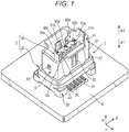
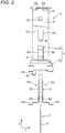
- Fig. 1 is a perspective view illustrating one use form of an electric connector 1, i.e., a state in which the electric connector 1 is soldered to a substrate 9, and Fig. 2 is an exploded side view of the electric connector 1.
- a partner connector (not shown) can be fitted to the electric connector 1 along a fitting direction " ⁇ 1." Moreover, the partner connector is separated from the electric connector 1 in a release direction " ⁇ 2" so that the connectors can be released from each other.
- a direction “ ⁇ ” along the fitting direction “ ⁇ 1" and the release direction “ ⁇ 2" with respect to the partner connector will be referred to as an "upper-lower direction” for the sake of convenience.
- a direction “ ⁇ ,” which is perpendicular to the upper-lower direction, along a longitudinal direction of a metal shell 6 will be referred to as a “right-left direction.”
- the side of fitting to or release from the partner connector will be referred to as an “upper” side with reference to the electric connector 1.
- these terms “upper,” “lower,” “left,” and “right” are merely used for the sake of convenience in distinguishing directions.
- the “upper” and the like do not have special meanings.
- the direction along the " ⁇ ” direction may be referred to as the "right-left direction” (the same applies below).
- the electric connector 1 includes a resin housing 2 and multiple terminals 41, the metal shell 6, and a shield 5 attached to the housing 2.
- the housing 2 includes a flat substantially-rectangular-parallelepiped base 20 and a thin plate-shaped body 30.
- the plate-shaped body 30 stands to extend upward of the base 20, i.e., extend to the side of fitting to the partner connector.
- Components of the electric connector 1 including the housing 2 have approximately bisymmetrical shapes, except for the plate-shaped body 30.
- the plate-shaped body 30 has a point symmetrical shape as viewed in plane. Note that as in other portions, the plate-shaped body 30 may have a bisymmetrical shape.
- the base 20 is formed in a step shape in the upper-lower direction.
- the base 20 may be formed in a two-step shape.
- a protrusion 25 extends downward of a bottom surface 20a of a lower step. The protrusion 25 can be used for positioning the housing 2 on the substrate 9 and fixing the housing 2 to the substrate 9.
- the plate-shaped body 30 extends upward of an upper step of the base 20, i.e., extends to the side of fitting to the partner connector.
- the thickness of the plate-shaped body 30 may be, for example, an extremely-thin thickness of about 1 to 3 mm.
- Each of characters "A,” "B” as described herein is a character indicating one plate surface side of the plate-shaped body 30. In a case where it is not necessary to distinguish one plate surface 30A and the other plate surface 30B from each other, these characters may be omitted (the same applies below).
- the shield 5 has a flat plate shape, and for example, has an extremely-thin thickness of about 0.1 to 0.3 mm.
- the shield 5 is inserted into the housing 2 from a lower step side to an upper step side of the base 20.
- the shield 5 is placed with the shield 5 extending over both of the base 20 and the plate-shaped body 30.
- the shield 5 is specifically arranged among the multiple first terminals 41A and the multiple second terminals 41B in the thickness direction " ⁇ " of the plate-shaped body 30. With this configuration, the first terminals 41A and the second terminals 41B are shielded from each other. As illustrated in Fig.
- the substantially entirety of the shield 5 is covered with the housing 2.
- the through-holes 35a are inevitably formed when a housing space for housing the shield 5 is formed using a die.
- the terminals 41 include five first terminals 41A arrayed on one plate surface 30A of the plate-shaped body 30 and five second terminals 41B arrayed on the other plate surface 30B. In the present embodiment, all of these terminals have the same shape. Note that these terminals do not necessarily have the same shape. Considering prevention of crosstalk, the first terminals 41A and the second terminals 41B are arrayed in a zigzag pattern on the plate-shaped body 30.
- Fig. 3 illustrates an enlarged perspective view of the terminal 41.
- Each terminal 41 has a substantially L-shape as viewed laterally.
- Each terminal 41 includes a contact portion 43 contactable with the partner connector and a press-fitting portion 42 to be press-fitted to a predetermined portion of the base 20, and further includes a mounting portion 44 to be soldered to, e.g., a pad 91 (see Fig. 1 ) of the substrate.
- a surface 43a of the terminal 41 is arranged on one of the plate surfaces 30A, 30B of the plate-shaped body 30 with part of the surface 43a being exposed.
- a bottom surface 43b and side surfaces 43c of the terminal 41 are arranged with these surfaces being embedded in the housing 2.
- laterally-protruding press-fitting protrusions 42a are provided on each of the right and left side surfaces 43c of the terminal 41. These press-fitting protrusions 42a are press-fitted to a predetermined portion of the housing 2, specifically the predetermined portion of the base 20, when the terminal 41 is placed in the housing 2. Accordingly, the terminal 41 is reliably fixed to the housing 2.
- biasing protruding portions 42b protruding outward of the surface 43a are provided in the vicinity of the press-fitting protrusions 42a at the surface 43a of the terminal 41.
- the biasing protruding portions 42b can contact a predetermined wall surface of the base 20 to press a tip end portion 43d of the contact portion 43 toward a bottom surface 43b side of the terminal 41.
- detachment of the terminal 41 from the housing 2 specifically detachment of the easily-detachable tip end portion 43d of the contact portion 43 of the terminal 41, can be effectively prevented.
- the shell 6 includes a main body 61 formed in a substantially tubular shape. Directing portions 60c are provided at an end portion of an opening 60b of the main body 61 on the side of fitting to the partner connector. The directing portions 60c are opened to the outside so that the partner connector can be directed into the shell 6. On the other hand, at an end portion of the main body 61 on a side opposite to the side of fitting to the partner connector, a pair of fixing pieces 65 is provided at an end portion of the main body 61 on a side opposite to the side of fitting to the partner connector. The pair of fixing pieces 65 extends to the side of attachment to the housing 2.
- the shell 6 is fixed to the housing 2 in such a manner that an end portion 61a of the main body 61 on the side opposite to the side of fitting to the partner connector is inserted and placed into an annular recessed groove 27 provided at the housing 2 and the fixing pieces 65 are press-fitted in through-holes 26 (see, e.g., Fig. 9 as described later) of the housing 2 by means of press-fitting protrusions 65a protruding from the sides of the fixing pieces 65.
- a fitting space 60a in which part of the partner connector is to be fitted is formed among an inner wall 63a of the main body 61, the plate-shaped body 30, such as one plate surface 30A and the other plate surface 30B, of the plate-shaped body 30 of the housing 2, and the terminals 41.
- lock holes 64 at which predetermined portions of the partner connector fitted in the fitting space 60a are locked are provided as through-holes at the main body 61.
- holding pieces 62 are provided in such a manner that part of a wall surface of the shell 6 is cut, raised, and bent slightly inward. With the holding pieces 62, the partner connector fitted in the fitting space 60a can electrically contact the shell 6, and through such contact, the partner connector can be connected to, e.g., ground.
- Figs. 4 to 9 are views of the individual housing 2.
- Figs. 10 to 12 illustrate the electric connector 1 as a finished article as in Fig. 1 .
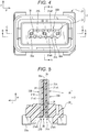
- Fig. 4 is a plan view of the housing 2.
- Fig. 5 is a sectional view along an A-Aline of Fig. 4 .
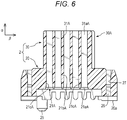
- Fig. 6 is a sectional view along a B-B line of Fig. 4 .
- Fig. 7 is a sectional view along a C-C line of Fig. 4 .
- Fig. 8 is a perspective view of Fig. 7 .
- Fig. 9 is a bottom view of the housing 2.
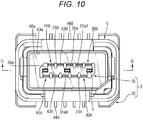
- Fig. 10 is a plan view of the electric connector 1.
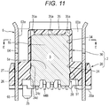
- Fig. 11 is a sectional view along a D-D line of Fig. 10 , the sectional view corresponding to Fig. 6 .
- Fig. 12 is a sectional view along an E-E line of Fig. 10 .
- Fig. 6 illustrates the side of one plate surface 30A.
- Figs. 7 , 8 , and 11 illustrate the side of the other plate surface 30B.
- the electric connector 1 has, except for the plate-shaped body 30, the bisymmetrical shape, and the plate-shaped body 30 has the point symmetrical shape as viewed in plane.
- one surface 30A and the other surface 30B can be taken as similar surfaces.
- multiple first protruding portions 31A form, on one plate surface 30A of the plate-shaped body 30, multiple first grooves 31aA in which the first terminals 41A are arranged.
- These first grooves 31aA are provided continuously to one plate surface 30A in the fitting-release direction " ⁇ .”
- these first grooves 31aA are arrayed with the first grooves 31aA being separated from each other at equal intervals in the direction " ⁇ " perpendicular to the fitting-release direction " ⁇ .”
- multiple second protruding portions 31B form, on the other plate surface 30B, multiple second grooves 31aB in which the second terminals 41B are arranged.
- These second grooves 31aB are provided continuously to the other plate surface 30B in the fitting-release direction " ⁇ .”
- these second grooves 31aB are arrayed with the second grooves 31aB being separated from each other at equal intervals in the direction " ⁇ " perpendicular to the fitting-release direction " ⁇ .”
- first terminal insertion holes 21A into which the first terminals 41A are inserted are provided at the base 20 along the fitting-release direction " ⁇ .”
- the first terminals 41A are each inserted into these first terminal insertion holes 21A.
- Five first terminal insertion holes 21A in total are, along the right-left direction " ⁇ ," formed corresponding to the number of first terminals 41A, e.g., five terminals in this embodiment.
- terminal insertion holes 21A are, in the " ⁇ " direction, divided from each other by first walls 21bA. Moreover, these first walls 21bA are provided along the fitting-release direction " ⁇ " in a state in which each first wall 21bA is aligned with the first protruding portion 31A provided on one plate surface 30A of the plate-shaped body 30. As a result, each first terminal insertion hole 21A is, in the fitting-release direction " ⁇ ," continuous to a corresponding one of the multiple first grooves 31aA formed at one plate surface 30A of the plate-shaped body 30 such that the first terminals 41A are each arranged in the first grooves 31aA. Utilizing the first terminal insertion holes 21A and the first grooves 31aA, the first terminals 41A are reliably arranged at predetermined positions on the base 20 and the plate-shaped body 30.
- a tapered portion 21aA is provided in the vicinity of an inlet at each terminal insertion hole 21A.
- the first terminal 41A is, at the contact portion 43 thereof (see Fig. 3 ), inserted into the first terminal insertion hole 21A through the tapered portion 21aA.
- the first terminal 41A is, at the press-fitting portion 21 thereof, press-fitted in a press-fitting portion 21cA of the first terminal insertion hole 21A.
- the first terminal 41A is fixed to the press-fitting portion 21cA.
- the mounting portion 44 of the first terminal 41A is arranged in a recessed groove 21dA dug corresponding to each first terminal insertion hole 21A at the bottom surface 20a of the base 20.
- multiple second terminal insertion holes 21B into which the second terminals 41B are inserted are provided along the fitting-release direction " ⁇ " at the base 20.
- the second terminals 41B are each inserted into these second terminal insertion holes 21B.
- Five first terminal insertion holes 21B are, along the right-left direction " ⁇ ,” formed corresponding to the number of second terminals 41B.
- These second terminal insertion holes 21B are, in the " ⁇ " direction, divided from each other by second walls 21bB. Moreover, these second walls 21bB are provided along the fitting-release direction " ⁇ " in a state in which each second wall 21bB is aligned with the first protruding portion 31B provided on the other plate surface 30B of the plate-shaped body 30. As a result, each second terminal insertion hole 21B is, in the fitting-release direction " ⁇ ," continuous to a corresponding one of the multiple second grooves 31aB formed at the other plate surface 30B of the plate-shaped body 30 such that the second terminals 41B are each arranged in the second grooves 31aB. Utilizing the second terminal insertion holes 21B and the first grooves 31aB, the second terminals 41B are reliably arranged at predetermined positions on the base 20 and the plate-shaped body 30.
- a tapered portion 21aB is provided in the vicinity of an inlet at each terminal insertion hole 21B.
- the first terminal 41B is, at the contact portion 43 thereof (see Fig. 3 ), inserted into the first terminal insertion hole 21B through the tapered portion 21aB.
- the first terminal 41B is, at the press-fitting portion 21 thereof, press-fitted in a press-fitting portion 21cB of the first terminal insertion hole 21B.
- the first terminal 41B is fixed to the press-fitting portion 21cB.
- the mounting portion 44 of the second terminal 41B is arranged in a recessed groove 21dB dug corresponding to each second terminal insertion hole 21B at the bottom surface 20a of the base 20.
- a great load is on the first walls 21bA dividing the first terminal insertion holes 21A from each other or the second walls 21bB dividing the second terminal insertion holes 21B from each other, specifically the press-fitting portions 21cA or the second press-fitting portions 21cB.
- reinforcing portions 36A, 36B having a great resin thickness are provided.
- the first reinforcing portions 36A are preferably provided at positions close to the first walls 21bA in an in-plane direction " ⁇ - ⁇ " perpendicular to the fitting-release direction " ⁇ ," such as positions facing each other in a thickness direction of a plate forming the housing space 24, 34. Specifically, the first reinforcing portion 36A is preferably provided close to the first press-fitting portion 21cA.
- first reinforcing portions 36A separated from each other in the " ⁇ " direction are provided to protrude from the inner walls 24aA, 34aA toward the inside of the first housing portion 24 and the second housing portion 34.
- the second reinforcing portions 36B are preferably provided at positions close to the second walls 21bB in the in-plane direction " ⁇ - ⁇ " perpendicular to the fitting-release direction " ⁇ ," such as opposing positions in the thickness direction on the front and back sides of the plate forming the housing space 24, 34.
- the second reinforcing portion 36B is preferably provided close to the second press-fitting portion 21cB.
- the second reinforcing portions 36B separated from each other in the " ⁇ " direction are provided to protrude from the inner walls 24aB, 34aB toward the inside of the first housing portion 24 and the second housing portion 34.
- the base 20 of the housing 2 has the substantially plate-shaped first housing portion 24 housing part 5a of the shield 5 (see Fig. 11 ).
- the plate-shaped body 30 of the housing 2 has the substantially plate-shaped second housing portion 34 housing another part 5b of the shield 5 (see Fig. 11 ).
- the first housing portion 24 and the second housing portion 34 form one housing space 24, 34 for housing the shield 5 in a state in which these portions are communicated with each other in the direction " ⁇ " of fitting to or release from the partner connector.
- a shield insertion hole 28 into which the shield 5 is inserted is provided at an inlet of the housing space 24, 34 at the base 20.
- the shield 5 is inserted into one housing space formed by the first housing portion 24 and the second housing portion 34 through the shield insertion hole 28 along the fitting-release direction " ⁇ " from the lower side to the upper side, i.e., from the side opposite to the side of fitting to the partner connector to the fitting side.
- a tapered portion 24d is preferably provided in the vicinity of an inlet at the shield insertion hole 28.
- the shield 5 is press-fitted in a press-fitting portion 24c (see Fig. 11 ) of the first housing portion 24, and is fixed at a predetermined position on the first housing portion 24.
- the shield 5 is extremely thin.
- the housing space 24, 34 in which the shield 5 is housed is also extremely thin, and for example, has only a thickness of about 0.1 to 0.4 mm.
- a die for forming the housing space 24, 34 is also extremely thin, corresponding to the shape and size of the housing space 24, 34.
- injection molding is performed in a state in which a die for forming the housing space 24, 34, specifically a die portion for forming the second housing portion 34, is held by a die portion extending from an end wall 35 of the plate-shaped body 30 positioned on the side of fitting to the partner connector.
- the second housing portion 34 is, in the fitting-release direction " ⁇ ," communicated with the through-holes 35a provided at the end wall 35 of the plate-shaped body 30.
- the through-hole 35a is a hole formed by the die portion extending from the end wall 35 of the plate-shaped body 30.
- the die portion extending through the through-holes 35a holds the die for forming the housing space 24, 34, specifically the die portion for forming the second housing portion 34. With this configuration, damage and position displacement of the die (the die portion) can be effectively prevented. Further, the electric connector having the housing space 24, 34 formed with the accurately-controlled shape and size for the shield 5 can be provided.
- the through-holes 35a are provided at three locations in the right-left direction " ⁇ .” The through-holes 35a are positioned at both end portions and a center portion of the housing space 24, 34.
- first reinforcing portions 36A and the second reinforcing portions 36B provided on the inner walls 24aA, 24aB of the first housing portion 24A and the inner walls 34aA, 34aB of the second housing portion 34 are not necessarily provided to partially protrude from the inner walls.
- the plate thickness can be increased by the entirety of the reinforcing portions.
- the thickness of the housing space 24, 34 is decreased by such a plate thickness increment.
- the die for forming the housing space 24, 34 is thinned. For this reason, in the present embodiment, the form in which the reinforcing portions only partially protrude is employed.
- Fig. 13 illustrates a sectional view of one example of a die applicable for manufacturing the housing 2. Specifically, this figure illustrates, as a sectional view corresponding to Fig. 5 , a die for forming the vicinity of the through-holes 35a provided at the end wall 35 of the plate-shaped body 30.
- the die for forming this portion includes at least a first die 72 and a second die 73.
- the first die 72 defines at least part of an outer surface of the end wall 35 of the plate-shaped body 30 and part of the through-holes 35a provided at the end wall 35.
- the second die 73 defines the housing space 34 (24) for housing the shield 5 and the remaining part of the through-holes 35a provided at the end wall 35. Needless to say, these dies may be divided as necessary, considering a die cutting process.
- a space (34, 24, 35a) formed by the first die 72 and the second die 73 is filled with resin, and in this manner, the housing 2 can be manufactured.
- the housing space 34 (24) and the end wall 35 having the through-holes 35a are formed.
- the first portion 72a and the second portion 73a can be coupled to each other by an inlay (fitting) structure.
- the space (24, 34) can be formed with accurate precision.
- the shield 5 can be, with high precision, housed at a predetermined position in the housing portion (24, 34).
Landscapes
- Engineering & Computer Science (AREA)
- Manufacturing & Machinery (AREA)
- Details Of Connecting Devices For Male And Female Coupling (AREA)
- Connector Housings Or Holding Contact Members (AREA)
- Manufacturing Of Electrical Connectors (AREA)
Abstract
Description
- The present invention relates to an electric connector having a shield. More specifically, the present invention relates to an electric connector having a shield among terminals provided on one surface of a plate-shaped body and terminals provided on the other surface of the plate-shaped body and the method for manufacturing a housing of the electric connector.
-
JP-A-2017-37851 - PATENT LITERATURE 1:
JP-A-2017-37851 - As clearly seen, in the technique disclosed in
Patent Literature 1, the shield can be provided integrally with the housing by insert molding. Thus, a housing space for housing the shield is not necessarily provided in advance. - On the other hand, in the technique of attaching the shield by press-fitting, the housing space for housing the shield needs to be formed in advance by means of a die. With recent device size reduction, the size of the housing space has decreased. For example, the thickness of the housing space is only about 0.1 to 0.4 mm in some cases. For forming, by means of the die, such a housing space expanding in an in-plane direction with the slight thickness, resin needs to be injected into the die defining the housing space with extremely-high pressure. As a result, damage of the die or position displacement of the die caused by the pressure of the injected resin occurs, and for this reason, it is difficult to accurately control the shape and size of the housing space.
- The invention of the present application has been made for solving these problems of the typical technique. An object of the invention of the present application is to effectively prevent damage and position displacement of a die to provide an electric connector having a shield housing space with accurately-controlled shape and size.
- In order to address the above-described object, an electric connector according to an aspect of the present invention includes: a housing including a base and a plate-shaped body formed on a side of the base fitted to a partner connector; multiple first terminals attached to the housing and provided in a state in which at least part of the multiple first terminals is exposed at one plate surface of the plate-shaped body and multiple second terminals provided in a state in which at least part of the multiple second terminals is exposed at the other plate surface of the plate-shaped body, the one plate surface and the other plate surface facing each other; a shield attached to the housing and arranged among the multiple first terminals and the multiple second terminals in a thickness direction of the plate-shaped body; and a metal shell attached to the housing and forming, between the one plate surface and the other plate surface, at least part of a fitting space in which part of the partner connector is to be fitted. The base has a first housing portion for housing part of the shield, the plate-shaped body has a second housing portion communicated with the first housing portion in a direction of fitting to or release from the partner connector and provided for housing another part of the shield, and the second housing portion is, in the fitting-release direction, communicated with a through-hole provided at an end wall of the plate-shaped body positioned on a side of fitting to the partner connector.
- In the electric connector according to the aspect, the base may have, along the fitting-release direction, multiple first terminal insertion holes into which the multiple first terminals are to be inserted and multiple second terminal insertion holes into which the multiple second terminals are inserted, the multiple first terminal insertion holes may be, in the fitting-release direction, continuous to multiple first grooves formed at the one plate surface such that the multiple first terminals are each arranged in the multiple first grooves, and the multiple first grooves may be arrayed separately from each other at the one plate surface, and the multiple second terminal insertion holes may be, in the fitting-release direction, continuous to multiple second grooves formed at the other plate surface such that the multiple second terminals are each arranged in the multiple second grooves, and the multiple second grooves may be arrayed separately from each other at the other plate surface.
- Further, in the electric connector according to the aspect, at the one plate surface, multiple first protruding portions forming at least part of the multiple first grooves may be provided along the fitting-release direction in a state in which the multiple first protruding portions are aligned with a first wall dividing the multiple first terminal insertion holes from each other in a direction perpendicular to the fitting-release direction, and at the other plate surface, multiple second protruding portions forming at least part of the multiple second grooves may be provided along the fitting-release direction in a state in which the multiple second protruding portions are aligned with a second wall dividing the multiple second terminal insertion holes from each other in the direction perpendicular to the fitting-release direction.
- Further, in the electric connector according to the aspect, on an inner wall of the first housing portion on a one-plate-surface side and an inner wall of the second housing portion on the one-plate-surface side along a plate surface direction of the plate-shaped body, multiple first reinforcing portions arrayed separately from each other in the direction perpendicular to the fitting-release direction may be provided to protrude from the inner walls to an inside of the first housing portion and the second housing portion, on an inner wall of the first housing portion on an other-plate-surface side and an inner wall of the second housing portion on the other-plate-surface side along the plate surface direction of the plate-shaped body, multiple second reinforcing portions arrayed separately from each other in the direction perpendicular to the fitting-release direction may be provided to protrude from the inner walls to the inside of the first housing portion and the second housing portion, and each of the multiple first reinforcing portion may be arranged close to the first wall in an in-plane direction perpendicular to the fitting-release direction, and each of the multiple second reinforcing portions may be arranged close to the second wall in the in-plane direction perpendicular to the fitting-release direction.
- Moreover, in the electric connector according to the aspect, it is preferred that a first press-fitting portion in which each first terminal is to be press-fitted is formed at each first terminal insertion hole, and the multiple first reinforcing portions are at least provided close to the first press-fitting portion, and a second press-fitting portion in which each second terminal is to be press-fitted is formed at each second terminal insertion hole, and the multiple second reinforcing portions are at least provided close to the second press-fitting portion.
- In order to manufacture the electric connector according to the above-described aspect, a method for manufacturing a housing of the electric connector according to an aspect of the present invention includes: preparing at least a first die defining at least part of an outer surface of the end wall of the plate-shaped body and part of the through-hole provided at the end wall and a second die defining a housing space in which the shield is housed and the remaining part of the through-hole provided at the end wall; and manufacturing the housing by filling a space formed by the first die and the second die with resin in a state in which a first portion of the first die for defining the part of the through-hole provided at the end wall and a second portion of the second die for forming the remaining part of the through-hole provided at the end wall are coupled to each other.
- According to the invention of the present application, damage and position displacement of the die are effectively prevented. Thus, the electric connector having the shield housing space with the accurately-controlled shape and size and the method for manufacturing the housing of the electric connector can be provided.
-
-
Fig. 1 is a perspective view illustrating one use form of an electric connector according to one embodiment of the present invention; -
Fig. 2 is an exploded side view of the electric connector ofFig. 1 ; -
Fig. 3 is an enlarged perspective view of a terminal used for the electric connector ofFig. 1 ; -
Fig. 4 is a plan view of a housing used for the electric connector ofFig. 1 ; -
Fig. 5 is a sectional view along an A-Aline ofFig. 4 ; -
Fig. 6 is a sectional view along a B-B line ofFig. 4 ; -
Fig. 7 is a sectional view along a C-C line ofFig. 4 ; -
Fig. 8 is a perspective view ofFig. 7 ; -
Fig. 9 is a bottom view of the housing used for the electric connector ofFig. 1 ; -
Fig. 10 is a plan view of the electric connector ofFig. 1 ; -
Fig. 11 is a sectional view along a D-D line ofFig. 10 , the sectional view corresponding toFig. 6 ; -
Fig. 12 is a sectional view along an E-E line ofFig. 10 ; and -
Fig. 13 is a sectional view illustrating one example of a die applicable to manufacturing of the housing used for the electric connector ofFig. 1 . - Hereinafter, an electric connector according to one preferred embodiment of the present invention will be described with reference to the attached drawings. For the sake of convenience in description, only the preferred embodiment will be described. Note that such an embodiment is not intended to limit the present invention, needless to say.
-
Fig. 1 is a perspective view illustrating one use form of anelectric connector 1, i.e., a state in which theelectric connector 1 is soldered to asubstrate 9, andFig. 2 is an exploded side view of theelectric connector 1. - A partner connector (not shown) can be fitted to the
electric connector 1 along a fitting direction "α1." Moreover, the partner connector is separated from theelectric connector 1 in a release direction "α2" so that the connectors can be released from each other. - Hereinafter, a direction "α" along the fitting direction "α1" and the release direction "α2" with respect to the partner connector will be referred to as an "upper-lower direction" for the sake of convenience. Moreover, a direction "β," which is perpendicular to the upper-lower direction, along a longitudinal direction of a
metal shell 6 will be referred to as a "right-left direction." Specifically, the side of fitting to or release from the partner connector will be referred to as an "upper" side with reference to theelectric connector 1. Note that in the present specification, these terms "upper," "lower," "left," and "right" are merely used for the sake of convenience in distinguishing directions. For example, the "upper" and the like do not have special meanings. For example, the direction along the "α" direction may be referred to as the "right-left direction" (the same applies below). - The
electric connector 1 includes aresin housing 2 andmultiple terminals 41, themetal shell 6, and ashield 5 attached to thehousing 2. - The
housing 2 includes a flat substantially-rectangular-parallelepiped base 20 and a thin plate-shaped body 30. The plate-shaped body 30 stands to extend upward of thebase 20, i.e., extend to the side of fitting to the partner connector. Components of theelectric connector 1 including thehousing 2 have approximately bisymmetrical shapes, except for the plate-shaped body 30. The plate-shaped body 30 has a point symmetrical shape as viewed in plane. Note that as in other portions, the plate-shapedbody 30 may have a bisymmetrical shape. - The
base 20 is formed in a step shape in the upper-lower direction. For example, thebase 20 may be formed in a two-step shape. Aprotrusion 25 extends downward of abottom surface 20a of a lower step. Theprotrusion 25 can be used for positioning thehousing 2 on thesubstrate 9 and fixing thehousing 2 to thesubstrate 9. - The plate-shaped
body 30 extends upward of an upper step of thebase 20, i.e., extends to the side of fitting to the partner connector. The thickness of the plate-shapedbody 30 may be, for example, an extremely-thin thickness of about 1 to 3 mm. On oneplate surface 30A and theother plate surface 30B of the plate-shapedbody 30 facing each other in a thickness direction "γ" of the plate-shapedbody 30, multiplefirst terminals 41A and multiplesecond terminals 41B are arrayed. Each of characters "A," "B" as described herein is a character indicating one plate surface side of the plate-shapedbody 30. In a case where it is not necessary to distinguish oneplate surface 30A and theother plate surface 30B from each other, these characters may be omitted (the same applies below). - The
shield 5 has a flat plate shape, and for example, has an extremely-thin thickness of about 0.1 to 0.3 mm. Theshield 5 is inserted into thehousing 2 from a lower step side to an upper step side of thebase 20. Theshield 5 is placed with theshield 5 extending over both of thebase 20 and the plate-shapedbody 30. When theshield 5 is placed in thehousing 2, theshield 5 is specifically arranged among the multiplefirst terminals 41A and the multiplesecond terminals 41B in the thickness direction "γ" of the plate-shapedbody 30. With this configuration, thefirst terminals 41A and thesecond terminals 41B are shielded from each other. As illustrated inFig. 1 , when theshield 5 is fixed to, e.g., the substrate, the substantially entirety of theshield 5 is covered with thehousing 2. In this state, only a minute portion of theshield 5 is slightly exposed to the outside through through-holes 35a of thehousing 2. As described below, the through-holes 35a are inevitably formed when a housing space for housing theshield 5 is formed using a die. - The
terminals 41 include fivefirst terminals 41A arrayed on oneplate surface 30A of the plate-shapedbody 30 and fivesecond terminals 41B arrayed on theother plate surface 30B. In the present embodiment, all of these terminals have the same shape. Note that these terminals do not necessarily have the same shape. Considering prevention of crosstalk, thefirst terminals 41A and thesecond terminals 41B are arrayed in a zigzag pattern on the plate-shapedbody 30. -
Fig. 3 illustrates an enlarged perspective view of the terminal 41. Each terminal 41 has a substantially L-shape as viewed laterally. Each terminal 41 includes acontact portion 43 contactable with the partner connector and a press-fittingportion 42 to be press-fitted to a predetermined portion of thebase 20, and further includes a mountingportion 44 to be soldered to, e.g., a pad 91 (seeFig. 1 ) of the substrate. - When the terminal 41 is, at the
contact portion 43, placed on thehousing 2, asurface 43a of the terminal 41 is arranged on one of the plate surfaces 30A, 30B of the plate-shapedbody 30 with part of thesurface 43a being exposed. On the other hand, abottom surface 43b andside surfaces 43c of the terminal 41 are arranged with these surfaces being embedded in thehousing 2. - At the press-fitting
portion 42, laterally-protruding press-fittingprotrusions 42a are provided on each of the right and left side surfaces 43c of the terminal 41. These press-fittingprotrusions 42a are press-fitted to a predetermined portion of thehousing 2, specifically the predetermined portion of thebase 20, when the terminal 41 is placed in thehousing 2. Accordingly, the terminal 41 is reliably fixed to thehousing 2. At the press-fittingportion 42, biasing protrudingportions 42b protruding outward of thesurface 43a are provided in the vicinity of the press-fittingprotrusions 42a at thesurface 43a of the terminal 41. When the terminal 41 is placed in thehousing 2, thebiasing protruding portions 42b can contact a predetermined wall surface of the base 20 to press atip end portion 43d of thecontact portion 43 toward abottom surface 43b side of the terminal 41. Thus, detachment of the terminal 41 from thehousing 2, specifically detachment of the easily-detachabletip end portion 43d of thecontact portion 43 of the terminal 41, can be effectively prevented. - The
shell 6 includes amain body 61 formed in a substantially tubular shape. Directingportions 60c are provided at an end portion of anopening 60b of themain body 61 on the side of fitting to the partner connector. The directingportions 60c are opened to the outside so that the partner connector can be directed into theshell 6. On the other hand, at an end portion of themain body 61 on a side opposite to the side of fitting to the partner connector, a pair of fixingpieces 65 is provided. The pair of fixingpieces 65 extends to the side of attachment to thehousing 2. Theshell 6 is fixed to thehousing 2 in such a manner that anend portion 61a of themain body 61 on the side opposite to the side of fitting to the partner connector is inserted and placed into an annular recessedgroove 27 provided at thehousing 2 and the fixingpieces 65 are press-fitted in through-holes 26 (see, e.g.,Fig. 9 as described later) of thehousing 2 by means of press-fittingprotrusions 65a protruding from the sides of the fixingpieces 65. - When the
shell 6 is placed at a predetermined position of thehousing 2, afitting space 60a in which part of the partner connector is to be fitted is formed among aninner wall 63a of themain body 61, the plate-shapedbody 30, such as oneplate surface 30A and theother plate surface 30B, of the plate-shapedbody 30 of thehousing 2, and theterminals 41. For example, lock holes 64 at which predetermined portions of the partner connector fitted in thefitting space 60a are locked are provided as through-holes at themain body 61. Moreover, at an outer wall of themain body 61, holdingpieces 62 are provided in such a manner that part of a wall surface of theshell 6 is cut, raised, and bent slightly inward. With the holdingpieces 62, the partner connector fitted in thefitting space 60a can electrically contact theshell 6, and through such contact, the partner connector can be connected to, e.g., ground. - The structure of the
electric connector 1 will be described in more detail with reference toFigs. 4 to 12 . -
Figs. 4 to 9 are views of theindividual housing 2.Figs. 10 to 12 illustrate theelectric connector 1 as a finished article as inFig. 1 . - More specifically,
Fig. 4 is a plan view of thehousing 2.Fig. 5 is a sectional view along an A-Aline ofFig. 4 .Fig. 6 is a sectional view along a B-B line ofFig. 4 .Fig. 7 is a sectional view along a C-C line ofFig. 4 .Fig. 8 is a perspective view ofFig. 7 .Fig. 9 is a bottom view of thehousing 2.Fig. 10 is a plan view of theelectric connector 1.Fig. 11 is a sectional view along a D-D line ofFig. 10 , the sectional view corresponding toFig. 6 .Fig. 12 is a sectional view along an E-E line ofFig. 10 . -
Fig. 6 illustrates the side of oneplate surface 30A. Moreover,Figs. 7 ,8 , and11 illustrate the side of theother plate surface 30B. As described above, theelectric connector 1 has, except for the plate-shapedbody 30, the bisymmetrical shape, and the plate-shapedbody 30 has the point symmetrical shape as viewed in plane. Thus, onesurface 30A and theother surface 30B can be taken as similar surfaces. - As illustrated in, e.g.,
Figs. 4 to 6 ,10 , and12 , multiple first protrudingportions 31A form, on oneplate surface 30A of the plate-shapedbody 30, multiple first grooves 31aA in which thefirst terminals 41A are arranged. These first grooves 31aA are provided continuously to oneplate surface 30A in the fitting-release direction "α." Moreover, these first grooves 31aA are arrayed with the first grooves 31aA being separated from each other at equal intervals in the direction "β" perpendicular to the fitting-release direction "α." - Similarly, multiple second protruding
portions 31B form, on theother plate surface 30B, multiple second grooves 31aB in which thesecond terminals 41B are arranged. These second grooves 31aB are provided continuously to theother plate surface 30B in the fitting-release direction "α." Moreover, these second grooves 31aB are arrayed with the second grooves 31aB being separated from each other at equal intervals in the direction "β" perpendicular to the fitting-release direction "α." - As illustrated in, e.g.,
Fig. 9 in addition toFigs. 5 and6 , multiple firstterminal insertion holes 21A into which thefirst terminals 41A are inserted are provided at thebase 20 along the fitting-release direction "α." Thefirst terminals 41A are each inserted into these firstterminal insertion holes 21A. Five firstterminal insertion holes 21A in total are, along the right-left direction "β," formed corresponding to the number offirst terminals 41A, e.g., five terminals in this embodiment. - These
terminal insertion holes 21A are, in the "β" direction, divided from each other by first walls 21bA. Moreover, these first walls 21bA are provided along the fitting-release direction "α" in a state in which each first wall 21bA is aligned with the first protrudingportion 31A provided on oneplate surface 30A of the plate-shapedbody 30. As a result, each firstterminal insertion hole 21A is, in the fitting-release direction "α," continuous to a corresponding one of the multiple first grooves 31aA formed at oneplate surface 30A of the plate-shapedbody 30 such that thefirst terminals 41A are each arranged in the first grooves 31aA. Utilizing the firstterminal insertion holes 21A and the first grooves 31aA, thefirst terminals 41A are reliably arranged at predetermined positions on thebase 20 and the plate-shapedbody 30. - For facilitating terminal insertion, a tapered portion 21aA is provided in the vicinity of an inlet at each
terminal insertion hole 21A. Thefirst terminal 41A is, at thecontact portion 43 thereof (seeFig. 3 ), inserted into the firstterminal insertion hole 21A through the tapered portion 21aA. Thefirst terminal 41A is, at the press-fitting portion 21 thereof, press-fitted in a press-fitting portion 21cA of the firstterminal insertion hole 21A. Utilizing the press-fitting protrusions 42aA protruding to the side of the press-fitting portion 21, thefirst terminal 41A is fixed to the press-fitting portion 21cA. In this state, the mountingportion 44 of thefirst terminal 41A is arranged in a recessed groove 21dA dug corresponding to each firstterminal insertion hole 21A at thebottom surface 20a of thebase 20. - Similarly, multiple second terminal insertion holes 21B into which the
second terminals 41B are inserted are provided along the fitting-release direction "α" at thebase 20. Thesecond terminals 41B are each inserted into these second terminal insertion holes 21B. Five first terminal insertion holes 21B are, along the right-left direction "β," formed corresponding to the number ofsecond terminals 41B. - These second terminal insertion holes 21B are, in the "β" direction, divided from each other by second walls 21bB. Moreover, these second walls 21bB are provided along the fitting-release direction "α" in a state in which each second wall 21bB is aligned with the first protruding
portion 31B provided on theother plate surface 30B of the plate-shapedbody 30. As a result, each secondterminal insertion hole 21B is, in the fitting-release direction "α," continuous to a corresponding one of the multiple second grooves 31aB formed at theother plate surface 30B of the plate-shapedbody 30 such that thesecond terminals 41B are each arranged in the second grooves 31aB. Utilizing the second terminal insertion holes 21B and the first grooves 31aB, thesecond terminals 41B are reliably arranged at predetermined positions on thebase 20 and the plate-shapedbody 30. - For facilitating terminal insertion, a tapered portion 21aB is provided in the vicinity of an inlet at each
terminal insertion hole 21B. Thefirst terminal 41B is, at thecontact portion 43 thereof (seeFig. 3 ), inserted into the firstterminal insertion hole 21B through the tapered portion 21aB. Thefirst terminal 41B is, at the press-fitting portion 21 thereof, press-fitted in a press-fitting portion 21cB of the firstterminal insertion hole 21B. Utilizing the press-fitting protrusions 42aB protruding to the side of the press-fitting portion 21, thefirst terminal 41B is fixed to the press-fitting portion 21cB. In this state, the mountingportion 44 of thesecond terminal 41B is arranged in a recessed groove 21dB dug corresponding to each secondterminal insertion hole 21B at thebottom surface 20a of thebase 20. - In some cases, when the terminals are inserted into the first and second
terminal insertion holes terminal insertion holes 21A from each other or the second walls 21bB dividing the second terminal insertion holes 21B from each other, specifically the press-fitting portions 21cA or the second press-fitting portions 21cB. For preventing damage of part of thehousing 2 among the first and secondterminal insertion holes housing space 24 due to the load, reinforcingportions - The first reinforcing
portions 36A are preferably provided at positions close to the first walls 21bA in an in-plane direction "β-γ" perpendicular to the fitting-release direction "α," such as positions facing each other in a thickness direction of a plate forming thehousing space portion 36A is preferably provided close to the first press-fitting portion 21cA. On an inner wall 24aA of a first housing portion 24A on the side of oneplate surface 30A and an inner wall 34aA of asecond housing portion 34 on the side of oneplate surface 30A along a plate surface direction "α-β" of the plate-shapedbody 30, the first reinforcingportions 36A separated from each other in the "β" direction are provided to protrude from the inner walls 24aA, 34aA toward the inside of thefirst housing portion 24 and thesecond housing portion 34. - Similarly, the second reinforcing
portions 36B are preferably provided at positions close to the second walls 21bB in the in-plane direction "β-γ" perpendicular to the fitting-release direction "α," such as opposing positions in the thickness direction on the front and back sides of the plate forming thehousing space portion 36B is preferably provided close to the second press-fitting portion 21cB. On an inner wall 24aB of a first housing portion 24B on the side of theother plate surface 30B and an inner wall 34aB of a second housing portion 34B on the side of oneplate surface 30B along the plate surface direction "α-β" of the plate-shapedbody 30, the second reinforcingportions 36B separated from each other in the "β" direction are provided to protrude from the inner walls 24aB, 34aB toward the inside of thefirst housing portion 24 and thesecond housing portion 34. - As clearly illustrated in, e.g.,
Figs. 5 ,7 ,8 , and11 , thebase 20 of thehousing 2 has the substantially plate-shapedfirst housing portion 24housing part 5a of the shield 5 (seeFig. 11 ). Moreover, the plate-shapedbody 30 of thehousing 2 has the substantially plate-shapedsecond housing portion 34 housing anotherpart 5b of the shield 5 (seeFig. 11 ). Thefirst housing portion 24 and thesecond housing portion 34 form onehousing space shield 5 in a state in which these portions are communicated with each other in the direction "α" of fitting to or release from the partner connector. - As clearly illustrated in
Fig. 9 in addition to, e.g.,Fig. 5 , ashield insertion hole 28 into which theshield 5 is inserted is provided at an inlet of thehousing space base 20. Theshield 5 is inserted into one housing space formed by thefirst housing portion 24 and thesecond housing portion 34 through theshield insertion hole 28 along the fitting-release direction "α" from the lower side to the upper side, i.e., from the side opposite to the side of fitting to the partner connector to the fitting side. For facilitating terminal insertion, a taperedportion 24d is preferably provided in the vicinity of an inlet at theshield insertion hole 28. Utilizing a press-fitting protrusion 51 (seeFigs. 2 and11 ) provided at the side of theshield 5 inserted through the taperedportion 24d, theshield 5 is press-fitted in a press-fittingportion 24c (seeFig. 11 ) of thefirst housing portion 24, and is fixed at a predetermined position on thefirst housing portion 24. - As described above, the
shield 5 is extremely thin. Thus, thehousing space shield 5 is housed is also extremely thin, and for example, has only a thickness of about 0.1 to 0.4 mm. In a case where thehousing space housing space housing space - In the present embodiment, for preventing damage and position displacement of the die, injection molding is performed in a state in which a die for forming the
housing space second housing portion 34, is held by a die portion extending from anend wall 35 of the plate-shapedbody 30 positioned on the side of fitting to the partner connector. As a result of injection molding performed in this method, thesecond housing portion 34 is, in the fitting-release direction "α," communicated with the through-holes 35a provided at theend wall 35 of the plate-shapedbody 30. The through-hole 35a is a hole formed by the die portion extending from theend wall 35 of the plate-shapedbody 30. In injection molding, the die portion extending through the through-holes 35a holds the die for forming thehousing space second housing portion 34. With this configuration, damage and position displacement of the die (the die portion) can be effectively prevented. Further, the electric connector having thehousing space shield 5 can be provided. The through-holes 35a are provided at three locations in the right-left direction "β." The through-holes 35a are positioned at both end portions and a center portion of thehousing space - Note that the first reinforcing
portions 36A and the second reinforcingportions 36B provided on the inner walls 24aA, 24aB of the first housing portion 24A and the inner walls 34aA, 34aB of thesecond housing portion 34 are not necessarily provided to partially protrude from the inner walls. The plate thickness can be increased by the entirety of the reinforcing portions. However, in this case, the thickness of thehousing space housing space -
Fig. 13 illustrates a sectional view of one example of a die applicable for manufacturing thehousing 2. Specifically, this figure illustrates, as a sectional view corresponding toFig. 5 , a die for forming the vicinity of the through-holes 35a provided at theend wall 35 of the plate-shapedbody 30. - The die for forming this portion includes at least a
first die 72 and asecond die 73. Thefirst die 72 defines at least part of an outer surface of theend wall 35 of the plate-shapedbody 30 and part of the through-holes 35a provided at theend wall 35. Thesecond die 73 defines the housing space 34 (24) for housing theshield 5 and the remaining part of the through-holes 35a provided at theend wall 35. Needless to say, these dies may be divided as necessary, considering a die cutting process. - In a state in which a
first portion 72a of thefirst die 72 for defining part of the through-holes 35a provided at theend wall 35 and asecond portion 73a of thesecond die 73 for forming the remaining part of the through-holes 35a provided at theend wall 35 are coupled to each other, a space (34, 24, 35a) formed by thefirst die 72 and thesecond die 73 is filled with resin, and in this manner, thehousing 2 can be manufactured. In this manner, the housing space 34 (24) and theend wall 35 having the through-holes 35a are formed. Note that thefirst portion 72a and thesecond portion 73a can be coupled to each other by an inlay (fitting) structure. By employing the inlay structure as described above, damage, deformation, and position displacement of thesecond die 73 can be reliably prevented even if thesecond die 73 is an extremely-thin plate-shaped body expanding in the in-plane direction "α-β." Thus, the space (24, 34) can be formed with accurate precision. Moreover, theshield 5 can be, with high precision, housed at a predetermined position in the housing portion (24, 34). - Description above relates to the preferred embodiment, and it should be understood that description above merely represents an article and the method for manufacturing the article. It can be recognized that modification and correction into different embodiments are obvious to those skilled in the art in light of teaching above. Thus, exemplary embodiments and substitute embodiments can be implemented without departing from the spirit of the article and the method described in the attached claims.
-
- 2
- Housing
- 5
- Shield
- 20
- Base
- 21A
- First terminal insertion hole
- 21B
- Second terminal insertion hole
- 21bA
- First wall
- 21bB
- Second wall
- 21cA
- First press-fitting portion
- 21cB
- Second press-fitting portion
- 24
- First housing portion
- 24aA
- Inner wall
- 24aB
- Inner wall
- 30
- Plate-shaped body
- 31A
- First protruding portion
- 31B
- Second protruding portion
- 31aA
- First groove
- 31aB
- Second groove
- 34
- Second housing portion
- 34aA
- Inner wall
- 34aB
- Inner wall
- 35
- End wall
- 35a
- Through-hole
- 36A
- First reinforcing portion
- 36B
- Second reinforcing portion
- 41A
- First terminal
- 41B
- Second terminal
- 60
- Shell
- 60a
- Fitting space
Claims (6)
- An electric connector comprising:a housing including a base and a plate-shaped body formed on a side of the base fitted to a partner connector;multiple first terminals attached to the housing and provided in a state in which at least part of the multiple first terminals is exposed at one plate surface of the plate-shaped body and multiple second terminals provided in a state in which at least part of the multiple second terminals is exposed at the other plate surface of the plate-shaped body, the one plate surface and the other plate surface facing each other;a shield attached to the housing and arranged among the multiple first terminals and the multiple second terminals in a thickness direction of the plate-shaped body; anda metal shell attached to the housing and forming, between the one plate surface and the other plate surface, at least part of a fitting space in which part of the partner connector is to be fitted,wherein the base has a first housing portion for housing part of the shield,the plate-shaped body has a second housing portion communicated with the first housing portion in a direction of fitting to or release from the partner connector and provided for housing another part of the shield, andthe second housing portion is, in the fitting-release direction, communicated with a through-hole provided at an end wall of the plate-shaped body positioned on a side of fitting to the partner connector.
- The electric connector according to claim 1, wherein
the base has, along the fitting-release direction, multiple first terminal insertion holes into which the multiple first terminals are to be inserted and multiple second terminal insertion holes into which the multiple second terminals are inserted,
the multiple first terminal insertion holes are, in the fitting-release direction, continuous to multiple first grooves formed at the one plate surface such that the multiple first terminals are each arranged in the multiple first grooves, and the multiple first grooves are arrayed separately from each other at the one plate surface, and
the multiple second terminal insertion holes are, in the fitting-release direction, continuous to multiple second grooves formed at the other plate surface such that the multiple second terminals are each arranged in the multiple second grooves, and the multiple second grooves are arrayed separately from each other at the other plate surface. - The electric connector according to claim 2, wherein
at the one plate surface, multiple first protruding portions forming at least part of the multiple first grooves are provided along the fitting-release direction in a state in which the multiple first protruding portions are aligned with a first wall dividing the multiple first terminal insertion holes from each other in a direction perpendicular to the fitting-release direction, and
at the other plate surface, multiple second protruding portions forming at least part of the multiple second grooves are provided along the fitting-release direction in a state in which the multiple second protruding portions are aligned with a second wall dividing the multiple second terminal insertion holes from each other in the direction β perpendicular to the fitting-release direction. - The electric connector according to claim 3, wherein
on an inner wall of the first housing portion on a one-plate-surface side and an inner wall of the second housing portion on the one-plate-surface side along a plate surface direction "α-β" of the plate-shaped body, multiple first reinforcing portions arrayed separately from each other in the direction perpendicular to the fitting-release direction are provided to protrude from the inner walls to an inside of the first housing portion and the second housing portion,
on an inner wall of the first housing portion on an other-plate-surface side and an inner wall of the second housing portion on the other-plate-surface side along the plate surface direction of the plate-shaped body, multiple second reinforcing portions arrayed separately from each other in the direction perpendicular to the fitting-release direction are provided to protrude from the inner walls to the inside of the first housing portion and the second housing portion, and
each of the multiple first reinforcing portion is arranged close to the first wall in an in-plane direction perpendicular to the fitting-release direction, and each of the multiple second reinforcing portions is arranged close to the second wall in the in-plane direction perpendicular to the fitting-release direction. - The electric connector according to claim 4, wherein
a first press-fitting portion in which each first terminal is to be press-fitted is formed at each first terminal insertion hole, and the multiple first reinforcing portions are at least provided close to the first press-fitting portion, and
a second press-fitting portion in which each second terminal is to be press-fitted is formed at each second terminal insertion hole, and the multiple second reinforcing portions are at least provided close to the second press-fitting portion. - A method for manufacturing a housing of the electric connector according to any one of claims 1 to 5, comprising:preparing at least a first die defining at least part of an outer surface of the end wall of the plate-shaped body and part of the through-hole provided at the end wall and a second die defining a housing space in which the shield is housed and the remaining part of the through-hole provided at the end wall; andmanufacturing the housing by filling a space formed by the first die and the second die with resin in a state in which a first portion of the first die for defining the part of the through-hole provided at the end wall and a second portion of the second die for forming the remaining part of the through-hole provided at the end wall are coupled to each other.
Applications Claiming Priority (2)
| Application Number | Priority Date | Filing Date | Title |
|---|---|---|---|
| JP2018119778A JP2020004494A (en) | 2018-06-25 | 2018-06-25 | Electrical connector having shield plate and method of manufacturing housing of electrical connector |
| PCT/JP2019/023701 WO2020004077A1 (en) | 2018-06-25 | 2019-06-14 | Electric connector having shielding plate, and manufacturing method for housing of electric connector |
Publications (3)
| Publication Number | Publication Date |
|---|---|
| EP3813207A1 true EP3813207A1 (en) | 2021-04-28 |
| EP3813207A4 EP3813207A4 (en) | 2022-04-06 |
| EP3813207B1 EP3813207B1 (en) | 2025-07-23 |
Family
ID=68986468
Family Applications (1)
| Application Number | Title | Priority Date | Filing Date |
|---|---|---|---|
| EP19825671.1A Active EP3813207B1 (en) | 2018-06-25 | 2019-06-14 | Electric connector having shielding plate, and manufacturing method for housing of electric connector |
Country Status (5)
| Country | Link |
|---|---|
| US (1) | US11424568B2 (en) |
| EP (1) | EP3813207B1 (en) |
| JP (2) | JP2020004494A (en) |
| CN (1) | CN112106263B (en) |
| WO (1) | WO2020004077A1 (en) |
Families Citing this family (3)
| Publication number | Priority date | Publication date | Assignee | Title |
|---|---|---|---|---|
| JP7507111B2 (en) * | 2021-03-03 | 2024-06-27 | ヒロセ電機株式会社 | Electrical Connectors |
| BE1029267B1 (en) * | 2021-04-01 | 2022-11-04 | Phoenix Contact Gmbh & Co | Method of manufacturing a contact unit and contact unit |
| CN115189166B (en) * | 2022-07-28 | 2024-12-13 | Oppo广东移动通信有限公司 | Electrical connector, charger and charging assembly |
Family Cites Families (28)
| Publication number | Priority date | Publication date | Assignee | Title |
|---|---|---|---|---|
| JPH05303988A (en) * | 1992-04-28 | 1993-11-16 | Matsushita Electric Works Ltd | Connector |
| US5221212A (en) * | 1992-08-27 | 1993-06-22 | Amp Incorporated | Shielding a surface mount electrical connector |
| JPH07114952A (en) * | 1993-10-19 | 1995-05-02 | Hirose Electric Co Ltd | Multi-pole electrical connector |
| JP3308132B2 (en) * | 1995-05-25 | 2002-07-29 | ケル株式会社 | Connector with ground plate |
| JP3703551B2 (en) * | 1996-01-17 | 2005-10-05 | 富士通コンポーネント株式会社 | connector |
| TW421302U (en) | 1998-12-18 | 2001-02-01 | Hon Hai Prec Ind Co Ltd | Electrical connector |
| JP4234714B2 (en) * | 2005-11-16 | 2009-03-04 | 日本航空電子工業株式会社 | Connector and connector assembly |
| CN1917297A (en) * | 2006-08-28 | 2007-02-21 | 东莞蔻玛电子有限公司 | Cable connector |
| US7625243B2 (en) * | 2007-06-13 | 2009-12-01 | Hon Hai Precision Ind. Co., Ltd. | Extension to version 2.0 universal serial bus connector with improved contact arrangement |
| JP2009283340A (en) * | 2008-05-23 | 2009-12-03 | Alps Electric Co Ltd | Method of manufacturing connector apparatus |
| JP5556261B2 (en) | 2010-03-12 | 2014-07-23 | オムロン株式会社 | connector |
| JP5587714B2 (en) * | 2010-09-22 | 2014-09-10 | ホシデン株式会社 | Shield case, connector and electronic equipment |
| US8398439B1 (en) * | 2011-12-14 | 2013-03-19 | Proconn Technology Co., Ltd. | Electrical connector |
| JP6227225B2 (en) * | 2012-04-16 | 2017-11-08 | 日本航空電子工業株式会社 | connector |
| US9184545B2 (en) * | 2014-01-30 | 2015-11-10 | Ting-Chi CHEN | Combination USB connector |
| CN204216285U (en) * | 2014-07-15 | 2015-03-18 | 番禺得意精密电子工业有限公司 | Electric connector |
| TWI593194B (en) * | 2014-11-21 | 2017-07-21 | 連展科技股份有限公司 | Electrical receptacle connector with shielding and grounding features |
| CN204391368U (en) * | 2015-01-05 | 2015-06-10 | 番禺得意精密电子工业有限公司 | Electric connector |
| JP6422815B2 (en) | 2015-04-21 | 2018-11-14 | 日本航空電子工業株式会社 | connector |
| JP6601092B2 (en) * | 2015-09-24 | 2019-11-06 | 株式会社オートネットワーク技術研究所 | connector |
| US9722362B2 (en) * | 2015-10-23 | 2017-08-01 | T-Conn Precision Corporation | Electrical connector with improved shielding shell |
| CN205724077U (en) * | 2016-03-25 | 2016-11-23 | 番禺得意精密电子工业有限公司 | Electric connector |
| JP6520891B2 (en) * | 2016-11-04 | 2019-05-29 | Smk株式会社 | Method of manufacturing electrical connector |
| CN206471572U (en) * | 2017-01-10 | 2017-09-05 | 富誉电子科技(淮安)有限公司 | Electric connector |
| US12478197B2 (en) * | 2017-03-14 | 2025-11-25 | Encompass Group, Llc | Metalized fabric heating blanket electrical connector |
| CN207098116U (en) * | 2017-07-18 | 2018-03-13 | 昆山全方位电子科技有限公司 | Electric connector |
| CN207490223U (en) * | 2017-10-17 | 2018-06-12 | 富士能电子(昆山)有限公司 | Electric connector |
| JP7292190B2 (en) * | 2019-11-29 | 2023-06-16 | ホシデン株式会社 | Ground terminal and connector with same |
-
2018
- 2018-06-25 JP JP2018119778A patent/JP2020004494A/en active Pending
-
2019
- 2019-06-14 EP EP19825671.1A patent/EP3813207B1/en active Active
- 2019-06-14 WO PCT/JP2019/023701 patent/WO2020004077A1/en not_active Ceased
- 2019-06-14 CN CN201980031445.7A patent/CN112106263B/en active Active
- 2019-06-14 US US17/255,259 patent/US11424568B2/en active Active
-
2022
- 2022-07-15 JP JP2022113846A patent/JP7369830B2/en active Active
Also Published As
| Publication number | Publication date |
|---|---|
| US11424568B2 (en) | 2022-08-23 |
| WO2020004077A1 (en) | 2020-01-02 |
| JP2020004494A (en) | 2020-01-09 |
| CN112106263A (en) | 2020-12-18 |
| US20210226374A1 (en) | 2021-07-22 |
| EP3813207A4 (en) | 2022-04-06 |
| CN112106263B (en) | 2022-01-11 |
| EP3813207B1 (en) | 2025-07-23 |
| JP7369830B2 (en) | 2023-10-26 |
| JP2022132490A (en) | 2022-09-08 |
Similar Documents
| Publication | Publication Date | Title |
|---|---|---|
| EP3361575B1 (en) | Connector | |
| CN101114748B (en) | Connector device | |
| US9331414B2 (en) | Electrical connector | |
| EP3813207B1 (en) | Electric connector having shielding plate, and manufacturing method for housing of electric connector | |
| KR20140096969A (en) | Connector | |
| US20090061661A1 (en) | Mezzanine-type electrical connectors | |
| KR102613520B1 (en) | A terminal for substrate-connection connector, a connector, and method for manufacturing the connector | |
| US11121479B2 (en) | Connector and connecting method | |
| US11271354B2 (en) | Electric connector manufacturing method and electric connector | |
| US11276978B2 (en) | Electric connector manufacturing method and electric connector | |
| US11398697B2 (en) | Connector and connector manufacturing method | |
| EP3813204A1 (en) | Connector device using lid member, and lid member | |
| KR101083987B1 (en) | Manufacturing method of connector | |
| JPH02177277A (en) | Guide construction of multi-contact point connector | |
| US9847605B2 (en) | Method of manufacturing an electrical connector having an insulative housing for two rows of terminals | |
| EP3543713A1 (en) | Electrical contact and electric component socket | |
| CN106486838B (en) | Drawer seat | |
| JP2006202644A (en) | Shell for electrical connector, electrical connector and manufacturing method thereof | |
| US8011093B2 (en) | Method of manufacturing connectors | |
| US20250266630A1 (en) | Connector and method for manufacturing connector | |
| JP2013026174A (en) | Socket for electronic component | |
| JP2020191187A (en) | Movable connector | |
| JP2020191186A (en) | Movable connector | |
| US20140038440A1 (en) | Electrical connector with cap for covering partial receiving holes | |
| JP2009283340A (en) | Method of manufacturing connector apparatus |
Legal Events
| Date | Code | Title | Description |
|---|---|---|---|
| STAA | Information on the status of an ep patent application or granted ep patent |
Free format text: STATUS: THE INTERNATIONAL PUBLICATION HAS BEEN MADE |
|
| PUAI | Public reference made under article 153(3) epc to a published international application that has entered the european phase |
Free format text: ORIGINAL CODE: 0009012 |
|
| STAA | Information on the status of an ep patent application or granted ep patent |
Free format text: STATUS: REQUEST FOR EXAMINATION WAS MADE |
|
| 17P | Request for examination filed |
Effective date: 20210111 |
|
| AK | Designated contracting states |
Kind code of ref document: A1 Designated state(s): AL AT BE BG CH CY CZ DE DK EE ES FI FR GB GR HR HU IE IS IT LI LT LU LV MC MK MT NL NO PL PT RO RS SE SI SK SM TR |
|
| AX | Request for extension of the european patent |
Extension state: BA ME |
|
| DAV | Request for validation of the european patent (deleted) | ||
| DAX | Request for extension of the european patent (deleted) | ||
| REG | Reference to a national code |
Ref country code: DE Ref legal event code: R079 Free format text: PREVIOUS MAIN CLASS: H01R0013658100 Ipc: H01R0013410000 Ref country code: DE Ref legal event code: R079 Ref document number: 602019072986 Country of ref document: DE Free format text: PREVIOUS MAIN CLASS: H01R0013658100 Ipc: H01R0013410000 |
|
| A4 | Supplementary search report drawn up and despatched |
Effective date: 20220303 |
|
| RIC1 | Information provided on ipc code assigned before grant |
Ipc: H01R 107/00 20060101ALN20220225BHEP Ipc: H01R 24/62 20110101ALN20220225BHEP Ipc: H01R 12/71 20110101ALN20220225BHEP Ipc: H01R 12/70 20110101ALN20220225BHEP Ipc: B29C 45/14 20060101ALN20220225BHEP Ipc: H01R 43/18 20060101ALI20220225BHEP Ipc: H01R 13/6587 20110101ALI20220225BHEP Ipc: H01R 13/41 20060101AFI20220225BHEP |
|
| STAA | Information on the status of an ep patent application or granted ep patent |
Free format text: STATUS: EXAMINATION IS IN PROGRESS |
|
| 17Q | First examination report despatched |
Effective date: 20240212 |
|
| GRAP | Despatch of communication of intention to grant a patent |
Free format text: ORIGINAL CODE: EPIDOSNIGR1 |
|
| STAA | Information on the status of an ep patent application or granted ep patent |
Free format text: STATUS: GRANT OF PATENT IS INTENDED |
|
| INTG | Intention to grant announced |
Effective date: 20250217 |
|
| RIC1 | Information provided on ipc code assigned before grant |
Ipc: H01R 107/00 20060101ALN20250210BHEP Ipc: H01R 24/62 20110101ALN20250210BHEP Ipc: H01R 12/71 20110101ALN20250210BHEP Ipc: H01R 12/70 20110101ALN20250210BHEP Ipc: B29C 45/14 20060101ALN20250210BHEP Ipc: H01R 43/18 20060101ALI20250210BHEP Ipc: H01R 13/6587 20110101ALI20250210BHEP Ipc: H01R 13/41 20060101AFI20250210BHEP |
|
| GRAS | Grant fee paid |
Free format text: ORIGINAL CODE: EPIDOSNIGR3 |
|
| GRAA | (expected) grant |
Free format text: ORIGINAL CODE: 0009210 |
|
| STAA | Information on the status of an ep patent application or granted ep patent |
Free format text: STATUS: THE PATENT HAS BEEN GRANTED |
|
| P01 | Opt-out of the competence of the unified patent court (upc) registered |
Free format text: CASE NUMBER: APP_27870/2025 Effective date: 20250611 |
|
| AK | Designated contracting states |
Kind code of ref document: B1 Designated state(s): AL AT BE BG CH CY CZ DE DK EE ES FI FR GB GR HR HU IE IS IT LI LT LU LV MC MK MT NL NO PL PT RO RS SE SI SK SM TR |
|
| REG | Reference to a national code |
Ref country code: GB Ref legal event code: FG4D |
|
| REG | Reference to a national code |
Ref country code: CH Ref legal event code: EP |
|
| REG | Reference to a national code |
Ref country code: DE Ref legal event code: R096 Ref document number: 602019072986 Country of ref document: DE |
|
| REG | Reference to a national code |
Ref country code: IE Ref legal event code: FG4D |
|
| REG | Reference to a national code |
Ref country code: NL Ref legal event code: MP Effective date: 20250723 |
|
| PG25 | Lapsed in a contracting state [announced via postgrant information from national office to epo] |
Ref country code: PT Free format text: LAPSE BECAUSE OF FAILURE TO SUBMIT A TRANSLATION OF THE DESCRIPTION OR TO PAY THE FEE WITHIN THE PRESCRIBED TIME-LIMIT Effective date: 20251124 |
|
| PG25 | Lapsed in a contracting state [announced via postgrant information from national office to epo] |
Ref country code: NL Free format text: LAPSE BECAUSE OF FAILURE TO SUBMIT A TRANSLATION OF THE DESCRIPTION OR TO PAY THE FEE WITHIN THE PRESCRIBED TIME-LIMIT Effective date: 20250723 |
|
| REG | Reference to a national code |
Ref country code: AT Ref legal event code: MK05 Ref document number: 1817435 Country of ref document: AT Kind code of ref document: T Effective date: 20250723 |
|
| PG25 | Lapsed in a contracting state [announced via postgrant information from national office to epo] |
Ref country code: IS Free format text: LAPSE BECAUSE OF FAILURE TO SUBMIT A TRANSLATION OF THE DESCRIPTION OR TO PAY THE FEE WITHIN THE PRESCRIBED TIME-LIMIT Effective date: 20251123 |
|
| PG25 | Lapsed in a contracting state [announced via postgrant information from national office to epo] |
Ref country code: NO Free format text: LAPSE BECAUSE OF FAILURE TO SUBMIT A TRANSLATION OF THE DESCRIPTION OR TO PAY THE FEE WITHIN THE PRESCRIBED TIME-LIMIT Effective date: 20251023 |
|
| REG | Reference to a national code |
Ref country code: LT Ref legal event code: MG9D |
|
| PG25 | Lapsed in a contracting state [announced via postgrant information from national office to epo] |
Ref country code: AT Free format text: LAPSE BECAUSE OF FAILURE TO SUBMIT A TRANSLATION OF THE DESCRIPTION OR TO PAY THE FEE WITHIN THE PRESCRIBED TIME-LIMIT Effective date: 20250723 |
|
| PG25 | Lapsed in a contracting state [announced via postgrant information from national office to epo] |
Ref country code: FI Free format text: LAPSE BECAUSE OF FAILURE TO SUBMIT A TRANSLATION OF THE DESCRIPTION OR TO PAY THE FEE WITHIN THE PRESCRIBED TIME-LIMIT Effective date: 20250723 |
|
| PG25 | Lapsed in a contracting state [announced via postgrant information from national office to epo] |
Ref country code: HR Free format text: LAPSE BECAUSE OF FAILURE TO SUBMIT A TRANSLATION OF THE DESCRIPTION OR TO PAY THE FEE WITHIN THE PRESCRIBED TIME-LIMIT Effective date: 20250723 |
|
| PG25 | Lapsed in a contracting state [announced via postgrant information from national office to epo] |
Ref country code: GR Free format text: LAPSE BECAUSE OF FAILURE TO SUBMIT A TRANSLATION OF THE DESCRIPTION OR TO PAY THE FEE WITHIN THE PRESCRIBED TIME-LIMIT Effective date: 20251024 |
|
| PG25 | Lapsed in a contracting state [announced via postgrant information from national office to epo] |
Ref country code: SE Free format text: LAPSE BECAUSE OF FAILURE TO SUBMIT A TRANSLATION OF THE DESCRIPTION OR TO PAY THE FEE WITHIN THE PRESCRIBED TIME-LIMIT Effective date: 20250723 |
|
| PG25 | Lapsed in a contracting state [announced via postgrant information from national office to epo] |
Ref country code: LV Free format text: LAPSE BECAUSE OF FAILURE TO SUBMIT A TRANSLATION OF THE DESCRIPTION OR TO PAY THE FEE WITHIN THE PRESCRIBED TIME-LIMIT Effective date: 20250723 |
|
| PG25 | Lapsed in a contracting state [announced via postgrant information from national office to epo] |
Ref country code: BG Free format text: LAPSE BECAUSE OF FAILURE TO SUBMIT A TRANSLATION OF THE DESCRIPTION OR TO PAY THE FEE WITHIN THE PRESCRIBED TIME-LIMIT Effective date: 20250723 Ref country code: PL Free format text: LAPSE BECAUSE OF FAILURE TO SUBMIT A TRANSLATION OF THE DESCRIPTION OR TO PAY THE FEE WITHIN THE PRESCRIBED TIME-LIMIT Effective date: 20250723 |
|
| PG25 | Lapsed in a contracting state [announced via postgrant information from national office to epo] |
Ref country code: RS Free format text: LAPSE BECAUSE OF FAILURE TO SUBMIT A TRANSLATION OF THE DESCRIPTION OR TO PAY THE FEE WITHIN THE PRESCRIBED TIME-LIMIT Effective date: 20251023 |
|
| PG25 | Lapsed in a contracting state [announced via postgrant information from national office to epo] |
Ref country code: ES Free format text: LAPSE BECAUSE OF FAILURE TO SUBMIT A TRANSLATION OF THE DESCRIPTION OR TO PAY THE FEE WITHIN THE PRESCRIBED TIME-LIMIT Effective date: 20250723 |
|
| PG25 | Lapsed in a contracting state [announced via postgrant information from national office to epo] |
Ref country code: SM Free format text: LAPSE BECAUSE OF FAILURE TO SUBMIT A TRANSLATION OF THE DESCRIPTION OR TO PAY THE FEE WITHIN THE PRESCRIBED TIME-LIMIT Effective date: 20250723 |
|
| PG25 | Lapsed in a contracting state [announced via postgrant information from national office to epo] |
Ref country code: DK Free format text: LAPSE BECAUSE OF FAILURE TO SUBMIT A TRANSLATION OF THE DESCRIPTION OR TO PAY THE FEE WITHIN THE PRESCRIBED TIME-LIMIT Effective date: 20250723 |
|
| PG25 | Lapsed in a contracting state [announced via postgrant information from national office to epo] |
Ref country code: IT Free format text: LAPSE BECAUSE OF FAILURE TO SUBMIT A TRANSLATION OF THE DESCRIPTION OR TO PAY THE FEE WITHIN THE PRESCRIBED TIME-LIMIT Effective date: 20250723 |
|
| PG25 | Lapsed in a contracting state [announced via postgrant information from national office to epo] |
Ref country code: CZ Free format text: LAPSE BECAUSE OF FAILURE TO SUBMIT A TRANSLATION OF THE DESCRIPTION OR TO PAY THE FEE WITHIN THE PRESCRIBED TIME-LIMIT Effective date: 20250723 |
|
| PG25 | Lapsed in a contracting state [announced via postgrant information from national office to epo] |
Ref country code: EE Free format text: LAPSE BECAUSE OF FAILURE TO SUBMIT A TRANSLATION OF THE DESCRIPTION OR TO PAY THE FEE WITHIN THE PRESCRIBED TIME-LIMIT Effective date: 20250723 Ref country code: SK Free format text: LAPSE BECAUSE OF FAILURE TO SUBMIT A TRANSLATION OF THE DESCRIPTION OR TO PAY THE FEE WITHIN THE PRESCRIBED TIME-LIMIT Effective date: 20250723 |