EP3813205A1 - Mat seal for an electrical connector - Google Patents
Mat seal for an electrical connector Download PDFInfo
- Publication number
- EP3813205A1 EP3813205A1 EP20193683.8A EP20193683A EP3813205A1 EP 3813205 A1 EP3813205 A1 EP 3813205A1 EP 20193683 A EP20193683 A EP 20193683A EP 3813205 A1 EP3813205 A1 EP 3813205A1
- Authority
- EP
- European Patent Office
- Prior art keywords
- grid
- mat seal
- material layer
- holes
- forming
- Prior art date
- Legal status (The legal status is an assumption and is not a legal conclusion. Google has not performed a legal analysis and makes no representation as to the accuracy of the status listed.)
- Granted
Links
Images



Classifications
-
- H—ELECTRICITY
- H01—ELECTRIC ELEMENTS
- H01R—ELECTRICALLY-CONDUCTIVE CONNECTIONS; STRUCTURAL ASSOCIATIONS OF A PLURALITY OF MUTUALLY-INSULATED ELECTRICAL CONNECTING ELEMENTS; COUPLING DEVICES; CURRENT COLLECTORS
- H01R13/00—Details of coupling devices of the kinds covered by groups H01R12/70 or H01R24/00 - H01R33/00
- H01R13/46—Bases; Cases
- H01R13/52—Dustproof, splashproof, drip-proof, waterproof, or flameproof cases
- H01R13/5219—Sealing means between coupling parts, e.g. interfacial seal
-
- H—ELECTRICITY
- H01—ELECTRIC ELEMENTS
- H01R—ELECTRICALLY-CONDUCTIVE CONNECTIONS; STRUCTURAL ASSOCIATIONS OF A PLURALITY OF MUTUALLY-INSULATED ELECTRICAL CONNECTING ELEMENTS; COUPLING DEVICES; CURRENT COLLECTORS
- H01R13/00—Details of coupling devices of the kinds covered by groups H01R12/70 or H01R24/00 - H01R33/00
- H01R13/46—Bases; Cases
- H01R13/52—Dustproof, splashproof, drip-proof, waterproof, or flameproof cases
- H01R13/5205—Sealing means between cable and housing, e.g. grommet
- H01R13/5208—Sealing means between cable and housing, e.g. grommet having at least two cable receiving openings
-
- H—ELECTRICITY
- H01—ELECTRIC ELEMENTS
- H01R—ELECTRICALLY-CONDUCTIVE CONNECTIONS; STRUCTURAL ASSOCIATIONS OF A PLURALITY OF MUTUALLY-INSULATED ELECTRICAL CONNECTING ELEMENTS; COUPLING DEVICES; CURRENT COLLECTORS
- H01R13/00—Details of coupling devices of the kinds covered by groups H01R12/70 or H01R24/00 - H01R33/00
- H01R13/46—Bases; Cases
- H01R13/52—Dustproof, splashproof, drip-proof, waterproof, or flameproof cases
- H01R13/5216—Dustproof, splashproof, drip-proof, waterproof, or flameproof cases characterised by the sealing material, e.g. gels or resins
-
- B—PERFORMING OPERATIONS; TRANSPORTING
- B29—WORKING OF PLASTICS; WORKING OF SUBSTANCES IN A PLASTIC STATE IN GENERAL
- B29C—SHAPING OR JOINING OF PLASTICS; SHAPING OF MATERIAL IN A PLASTIC STATE, NOT OTHERWISE PROVIDED FOR; AFTER-TREATMENT OF THE SHAPED PRODUCTS, e.g. REPAIRING
- B29C45/00—Injection moulding, i.e. forcing the required volume of moulding material through a nozzle into a closed mould; Apparatus therefor
- B29C45/14—Injection moulding, i.e. forcing the required volume of moulding material through a nozzle into a closed mould; Apparatus therefor incorporating preformed parts or layers, e.g. injection moulding around inserts or for coating articles
- B29C45/14778—Injection moulding, i.e. forcing the required volume of moulding material through a nozzle into a closed mould; Apparatus therefor incorporating preformed parts or layers, e.g. injection moulding around inserts or for coating articles the article consisting of a material with particular properties, e.g. porous, brittle
- B29C45/14786—Fibrous material or fibre containing material, e.g. fibre mats or fibre reinforced material
-
- B—PERFORMING OPERATIONS; TRANSPORTING
- B29—WORKING OF PLASTICS; WORKING OF SUBSTANCES IN A PLASTIC STATE IN GENERAL
- B29C—SHAPING OR JOINING OF PLASTICS; SHAPING OF MATERIAL IN A PLASTIC STATE, NOT OTHERWISE PROVIDED FOR; AFTER-TREATMENT OF THE SHAPED PRODUCTS, e.g. REPAIRING
- B29C45/00—Injection moulding, i.e. forcing the required volume of moulding material through a nozzle into a closed mould; Apparatus therefor
- B29C45/16—Making multilayered or multicoloured articles
-
- H—ELECTRICITY
- H01—ELECTRIC ELEMENTS
- H01R—ELECTRICALLY-CONDUCTIVE CONNECTIONS; STRUCTURAL ASSOCIATIONS OF A PLURALITY OF MUTUALLY-INSULATED ELECTRICAL CONNECTING ELEMENTS; COUPLING DEVICES; CURRENT COLLECTORS
- H01R13/00—Details of coupling devices of the kinds covered by groups H01R12/70 or H01R24/00 - H01R33/00
- H01R13/46—Bases; Cases
- H01R13/52—Dustproof, splashproof, drip-proof, waterproof, or flameproof cases
- H01R13/521—Sealing between contact members and housing, e.g. sealing insert
-
- H—ELECTRICITY
- H01—ELECTRIC ELEMENTS
- H01R—ELECTRICALLY-CONDUCTIVE CONNECTIONS; STRUCTURAL ASSOCIATIONS OF A PLURALITY OF MUTUALLY-INSULATED ELECTRICAL CONNECTING ELEMENTS; COUPLING DEVICES; CURRENT COLLECTORS
- H01R13/00—Details of coupling devices of the kinds covered by groups H01R12/70 or H01R24/00 - H01R33/00
- H01R13/46—Bases; Cases
- H01R13/52—Dustproof, splashproof, drip-proof, waterproof, or flameproof cases
- H01R13/5219—Sealing means between coupling parts, e.g. interfacial seal
- H01R13/5221—Sealing means between coupling parts, e.g. interfacial seal having cable sealing means
-
- H—ELECTRICITY
- H01—ELECTRIC ELEMENTS
- H01R—ELECTRICALLY-CONDUCTIVE CONNECTIONS; STRUCTURAL ASSOCIATIONS OF A PLURALITY OF MUTUALLY-INSULATED ELECTRICAL CONNECTING ELEMENTS; COUPLING DEVICES; CURRENT COLLECTORS
- H01R43/00—Apparatus or processes specially adapted for manufacturing, assembling, maintaining, or repairing of line connectors or current collectors or for joining electric conductors
- H01R43/005—Apparatus or processes specially adapted for manufacturing, assembling, maintaining, or repairing of line connectors or current collectors or for joining electric conductors for making dustproof, splashproof, drip-proof, waterproof, or flameproof connection, coupling, or casing
-
- B—PERFORMING OPERATIONS; TRANSPORTING
- B29—WORKING OF PLASTICS; WORKING OF SUBSTANCES IN A PLASTIC STATE IN GENERAL
- B29K—INDEXING SCHEME ASSOCIATED WITH SUBCLASSES B29B, B29C OR B29D, RELATING TO MOULDING MATERIALS OR TO MATERIALS FOR MOULDS, REINFORCEMENTS, FILLERS OR PREFORMED PARTS, e.g. INSERTS
- B29K2313/00—Use of textile products or fabrics as reinforcement
-
- B—PERFORMING OPERATIONS; TRANSPORTING
- B29—WORKING OF PLASTICS; WORKING OF SUBSTANCES IN A PLASTIC STATE IN GENERAL
- B29L—INDEXING SCHEME ASSOCIATED WITH SUBCLASS B29C, RELATING TO PARTICULAR ARTICLES
- B29L2031/00—Other particular articles
- B29L2031/26—Sealing devices, e.g. packaging for pistons or pipe joints
-
- B—PERFORMING OPERATIONS; TRANSPORTING
- B29—WORKING OF PLASTICS; WORKING OF SUBSTANCES IN A PLASTIC STATE IN GENERAL
- B29L—INDEXING SCHEME ASSOCIATED WITH SUBCLASS B29C, RELATING TO PARTICULAR ARTICLES
- B29L2031/00—Other particular articles
- B29L2031/34—Electrical apparatus, e.g. sparking plugs or parts thereof
- B29L2031/36—Plugs, connectors, or parts thereof
-
- B—PERFORMING OPERATIONS; TRANSPORTING
- B29—WORKING OF PLASTICS; WORKING OF SUBSTANCES IN A PLASTIC STATE IN GENERAL
- B29L—INDEXING SCHEME ASSOCIATED WITH SUBCLASS B29C, RELATING TO PARTICULAR ARTICLES
- B29L2031/00—Other particular articles
- B29L2031/726—Fabrics
-
- H—ELECTRICITY
- H01—ELECTRIC ELEMENTS
- H01R—ELECTRICALLY-CONDUCTIVE CONNECTIONS; STRUCTURAL ASSOCIATIONS OF A PLURALITY OF MUTUALLY-INSULATED ELECTRICAL CONNECTING ELEMENTS; COUPLING DEVICES; CURRENT COLLECTORS
- H01R13/00—Details of coupling devices of the kinds covered by groups H01R12/70 or H01R24/00 - H01R33/00
- H01R13/46—Bases; Cases
- H01R13/502—Bases; Cases composed of different pieces
- H01R13/504—Bases; Cases composed of different pieces different pieces being moulded, cemented, welded, e.g. ultrasonic welding, or swaged together
-
- H—ELECTRICITY
- H01—ELECTRIC ELEMENTS
- H01R—ELECTRICALLY-CONDUCTIVE CONNECTIONS; STRUCTURAL ASSOCIATIONS OF A PLURALITY OF MUTUALLY-INSULATED ELECTRICAL CONNECTING ELEMENTS; COUPLING DEVICES; CURRENT COLLECTORS
- H01R2107/00—Four or more poles
Definitions
- the present invention relates to a mat seal for an electrical connector.
- Connectors are often used in automotive engineering, for example, to reliably connect a number of electrical lines with each other both electrically and mechanically.
- the connector comprises a plug and a mating plug which engage with each other in a mechanically and electrically connected state.
- the plug and the mating plug each have an electrically non-conductive housing, for example, made of plastic.
- the housings are geometrically designed in such a way that a mechanical and electrical connection is obtained between the plug and the mating plug after they are plugged together.
- a large number of cables are typically inserted into the plug and mating plug, which are mechanically connected to the housing of the plug or mating plug, respectively.
- the ends of the cables held in the plug are brought into contact with the ends of the cables held in the mating plug, thus providing a reliable electrical contact between the cables of the plug and those of the mating plug.
- the ends of the cables may also have suitably shaped contact pins for mechanical and electrical contact between the respective cable ends.
- connectors For such connectors, it may be necessary to protect the contact points between the cable ends from the penetration of dirt or moisture, especially in automotive applications.
- connectors are often equipped with mat seals.
- the mat seal is typically made of an elastic material, such as a silicone, rubber or polymer material.
- the mat seal is held in the housing of the plug and/or mating plug, for example, by means of a pressure plate.
- the mat seals In connectors that are intended to connect a large number of contacts or cables, the mat seals have many through-holes. A cable can pass through each of these trough-holes from an outside of the connector to an inside of the connector.
- the through-holes of the mat seal have cross sections such that the mat seal fits tightly against a fed through cable in the area of a circumference of a through-hole.
- the respective through-hole typically has, at least in partial areas, a smaller internal cross section than the cross section of a cable to be fed through.
- the deformations can lead to such a displacement of adjacent through-holes that incorrect installation and thus incorrect contacts and also damage to cables, wires or contacts which are to be guided through the through-holes but hit the displaced material of the mat seal can occur.
- a mat seal for an electrical connector wherein the mat seal comprises a plurality of through-holes extending through the mat seal in a through-hole direction; a grid of a first material having grid meshes and being arranged such that the through-holes extend through the grid meshes; a first material layer of a second material arranged on a first side of the grid; and a second material layer of a third material disposed on a second side of the grid opposite the first side; and wherein the first material of the grid has a greater compression modulus than the second material of the first material layer and the third material of the second material layer.
- the through-holes extending through the mat seal extend through the first material layer, the meshes of the grid and the second material layer.
- the meshes of the grid can be partially filled with the second and/or third material.
- grid also includes a grid band or net or net band; no distinction is made between these terms here.
- the grid can also be a grid band or net or net band (e.g. a fabric band).
- the plug and mating plug of the connector are mechanically and electrically connected to each other through the through-holes of the mat seal, for example, by cables, wires or contacts.
- the grid can be much thinner than the first and second material layers. Thus, for example, it may only extend in the through-hole direction by a maximum of 1/100 to 1/10, in particular, 1/100 to 1/80 or 1/50, or 1/80 to 1/20, for example, 1/60 to 1/30, of the thickness of the first material layer and/or the thickness of the second material layer in the through-hole direction.
- the grid can be a fabric band of the mentioned thickness.
- the thickness of the first and the second material layer can be the same or different from each other.
- the provision of the grid with a less compressible material (first material) compared to the materials of the first and second material layers (second and third material) provides the advantages of an overall reduced and controlled material deformation when feeding through the electrical connections (cables, wires or contacts), an increased stiffness and strength of the mat seal and consequently increased safety against installation faults (non-contact or faulty contact) and tightness, in particular, against moisture/water.
- the second and third materials can be the same.
- the first material layer can be formed integrally with the second material layer.
- the grid may be overmoulded by the first material layer and the second material layer.
- the grid can consist of a fibre net, in particular, a fibre net made of synthetic resin.
- a fibre net made of synthetic resin.
- the second material of the first material layer and the third material of the second material layer can be or comprise an elastic silicone, rubber or polymer material.
- the through-holes may have any geometric (surface) shape, for example, round or rectangular shapes. All through-holes may have the same diameter/cross sectional areas. In this case, the mesh size of the grid in the above mentioned embodiments may be larger than the diameter/cross sectional areas of the through-holes in the first and second material layers. In this way a contact with a controlled deformation of the second and third materials can be reliably achieved.
- the cross-sectional area of each through-hole in both the first material layer and the second material layer may vary in the through-hole direction, for example, due to the provision of a sealing lip.
- the cross-sectional area or “the diameter” of a through-hole in the first or second material layer is understood to be the largest cross-sectional area or diameter in the through-hole direction in the case that a cross-sectional area or diameter varies in the through-hole direction.
- the meshes may be of square or circular shape (same mesh size in longitudinal and transverse direction perpendicular to the through-hole direction).
- other geometric shapes are also possible, so that the mesh size of the grid in the plane perpendicular to the direction of the through-hole in the longitudinal direction is different from that in the transverse direction.
- the "mesh size" of the grid here and in the following is understood to be the smaller one of the mesh size in the longitudinal direction and that in the transverse direction.
- the mesh size or, respectively, the mesh size in the longitudinal direction and the mesh size in the transverse direction shall be considered constant (i.e. they do not vary in the longitudinal or transverse direction).
- the grid in the above described embodiments may have a constant mesh size which is larger than the largest diameter or the largest cross-sectional area of the through-holes in the first and second material layers.
- the mesh size may vary in the transverse or longitudinal direction according to the different cross-sectional areas of the through-holes.
- the cross-sectional area of the grid mesh associated with it is larger than the cross-sectional area of the through-hole.
- a multipole connector for example, with 80 contact poles, is provided with a plug and a mating plug and a mat seal according to one of the examples described above, which, in the closed state of the connector (i.e. the plug is engaged with the mating plug), is arranged between the plug and mating plug, wherein the mat seal provides a through-hole for each pole (pin).
- the mat seal may be retained by the plug and/or mating plug by means of a suitable retaining device.
- grid meshes of the grid can be partially filled with the second and/or third material.
- Formation of the first and second material layers may include overmolding the grid with the second and third materials.
- the formation of the grid may include injection moulding of the grid.
- Forming the grid may comprise forming a web of fabric band (fabric web) and the method may further comprise overmoulding the web of fabric band and dividing the overmoulded web of fabric band to form a plurality of mat seals (and hence the above-mentioned mat seal).
- forming the grid comprises forming a fabric web and the method further comprises cutting a fabric band from the fabric web to provide the grid.
- a plurality of grids can be produced from the fabric web which can be used to produce a plurality of mat seals in mass production.
- a mat seal for an electrical connector which can be manufactured according to one of the above-described examples of the method of manufacturing a mat seal for an electrical connector according to the invention.
- the present invention provides a mat seal for a connector comprising a plug and a mating plug, wherein the mat seal guarantees a reliable mechanical and electrical contact of plug and mating plug through the mat seal with secure sealing against water and dirt.
- the mat seal can be used in automotive applications, for example.
- the mat seal 10 comprises a grid 11 (or grid band or net or net band), which is arranged between a first material layer 12 and a second material layer 13.
- the mat seal 10 has through-holes 14 formed partly in the first material layer 12 (14a) and partly in the second material layer 12 (14b) and extending through grid meshes 11a of the grid 11 in the through-hole direction (i.e. substantially perpendicular to the grid meshes 11a).
- the cross sections of the through-holes 14, 14a, 14b may vary within the first material layer 12 and/or second material layer 13, for example, decrease towards the grid 11, and sealing lips may be formed in through-holes 14, 14a, 14b in the vicinity of the grid 11.
- the first material layer 12 and the second material layer 13 may be formed from the same material and, in particular, in one piece.
- the first material layer 12 and the second material layer 13 may be made of or comprise a silicone, rubber or polymer material.
- the grid 11 may be made of or include a plastic material.
- Such a grid 11 is also shown in Figure 2 and comprises grid meshes 11a with regular mesh sizes in the transverse direction Q and/or longitudinal direction L (as shown in Figures 1 and 2 ) or alternatively with irregular mesh sizes in the transverse direction Q and/or longitudinal direction L.
- the grid may, for example, be provided in the form of a fibre net made of plastic or a fabric band of plastic.
- the material selected for the grid 11 is less compressible than the material selected for the first material layer 12 and the second material layer 13.
- a deformation of the material of the first material layer 12 and second material layer 13 is controlled and reduced when cables (leads, contacts) are fed through the through-holes 14, 14a, 14b.
- a deformation of the material of the first material layer 12 and second material layer 13 in the plane perpendicular to the through-hole direction is controlled and reduced when a cable is fed through a through-hole through the grid.
- a mat seal as described above can be used in the connector 20 shown in Figure 3 .
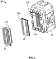
- an embodiment of a connector 20 according to the invention comprises a multipole plug 21 with a plurality of contacts 21a, a mat seal 22 with through-holes 22a, for example, the mat seal 11 shown in Figure 1 , and a mating plug 23.
- the mat seal 22 can be received in a receptacle 23a of the mating plug 23.
- cables (not shown) connected to contacts 21a of connector 21 are connected to contact receptacles (contacts) 23b of the mating plug 23 through the through-holes 22a of the mat seal 22.
- the mat seal 10 shown in Figure 1 or the mat seal 22 shown in Figure 3 can be made using a multi-component injection molding process with overmolding of the grid. This can be done using an injection moulding machine equipped with two independently controlled injection units and a corresponding control device.
- a grid such as grid 11 shown in Figures 1 and 2
- the injection moulded grid is transferred to a second injection mould 32.
- the grid is overmoulded with an elastic material, such as the material of the first and second material layers 12, 13 shown in Figure 1 .
- mandrels may be provided so that through holes can be made in the grid seal during forced demoulding.
- a grid in the form of a fabric band is used.
- a fabric web is formed 41, the fabric web having grid meshes.
- the fabric web can be temporarily stored on a roll 42.
- the fabric web In order to use the fabric web for the production of a large number of mat seals, for example, of the type shown in Figures 1 and 3 , it is at least partially uncoiled again and fed in unrolled condition to an injection mould 43.
- a suitable material for example, silicone
- a mat seal with a fabric band contained therein can then be produced.
- the fabric web can be tailored into individual fabric bands and a mat seal can be produced by overmoulding each fabric band, or a larger section of the fabric web is overmoulded and then the overmoulded section of the fabric web is tailored to form individual mat seals therefrom.
Landscapes
- Engineering & Computer Science (AREA)
- Manufacturing & Machinery (AREA)
- Mechanical Engineering (AREA)
- Chemical & Material Sciences (AREA)
- Dispersion Chemistry (AREA)
- Connector Housings Or Holding Contact Members (AREA)
Abstract
Description
- The present invention relates to a mat seal for an electrical connector.
- Connectors are often used in automotive engineering, for example, to reliably connect a number of electrical lines with each other both electrically and mechanically. The connector comprises a plug and a mating plug which engage with each other in a mechanically and electrically connected state. The plug and the mating plug each have an electrically non-conductive housing, for example, made of plastic. The housings are geometrically designed in such a way that a mechanical and electrical connection is obtained between the plug and the mating plug after they are plugged together.
- A large number of cables (or wires or contacts) are typically inserted into the plug and mating plug, which are mechanically connected to the housing of the plug or mating plug, respectively. When the plug and mating plug are mated with each other, the ends of the cables held in the plug are brought into contact with the ends of the cables held in the mating plug, thus providing a reliable electrical contact between the cables of the plug and those of the mating plug. The ends of the cables may also have suitably shaped contact pins for mechanical and electrical contact between the respective cable ends.
- For such connectors, it may be necessary to protect the contact points between the cable ends from the penetration of dirt or moisture, especially in automotive applications. For this purpose, connectors are often equipped with mat seals. The mat seal is typically made of an elastic material, such as a silicone, rubber or polymer material. The mat seal is held in the housing of the plug and/or mating plug, for example, by means of a pressure plate.
- In connectors that are intended to connect a large number of contacts or cables, the mat seals have many through-holes. A cable can pass through each of these trough-holes from an outside of the connector to an inside of the connector. The through-holes of the mat seal have cross sections such that the mat seal fits tightly against a fed through cable in the area of a circumference of a through-hole. For this purpose, the respective through-hole typically has, at least in partial areas, a smaller internal cross section than the cross section of a cable to be fed through.
- When the cables are fed through the mat seal, frictional forces which occur due to the tight-fitting mat seal must be overcome. Elastic deformation and compression of the material within the sealing mat occur. Particularly, if the diameter of a cable to be fed through is significantly larger than the cross-section of the corresponding through-hole, the material compressions that occur can generate strong radial forces applied to the cable, which can result in damages when the cable is fed through the through-hole. However, damages of the through-holes result in that sealing against moisture and dirt can no longer be guaranteed.
- Furthermore, the deformations can lead to such a displacement of adjacent through-holes that incorrect installation and thus incorrect contacts and also damage to cables, wires or contacts which are to be guided through the through-holes but hit the displaced material of the mat seal can occur.
- Therefore, it is an object of the present invention to provide a mat seal for a multipole connector which guarantees a correct electrical contact and, after the plug and mating plug have been connected, ensures and permanently maintains a reliable seal against moisture and dirt.
- The above-mentioned object is addressed by providing a mat seal for an electrical connector (with plug and mating plug), wherein the mat seal comprises
a plurality of through-holes extending through the mat seal in a through-hole direction;
a grid of a first material having grid meshes and being arranged such that the through-holes extend through the grid meshes;
a first material layer of a second material arranged on a first side of the grid; and
a second material layer of a third material disposed on a second side of the grid opposite the first side; and wherein
the first material of the grid has a greater compression modulus than the second material of the first material layer and the third material of the second material layer. - Thus the through-holes extending through the mat seal extend through the first material layer, the meshes of the grid and the second material layer. The meshes of the grid can be partially filled with the second and/or third material.
- Here and in the following, the term "grid" also includes a grid band or net or net band; no distinction is made between these terms here. In other words, the grid can also be a grid band or net or net band (e.g. a fabric band).
- The plug and mating plug of the connector are mechanically and electrically connected to each other through the through-holes of the mat seal, for example, by cables, wires or contacts. The grid can be much thinner than the first and second material layers. Thus, for example, it may only extend in the through-hole direction by a maximum of 1/100 to 1/10, in particular, 1/100 to 1/80 or 1/50, or 1/80 to 1/20, for example, 1/60 to 1/30, of the thickness of the first material layer and/or the thickness of the second material layer in the through-hole direction. In particular, the grid can be a fabric band of the mentioned thickness. The thickness of the first and the second material layer can be the same or different from each other.
- In accordance with the invention, the provision of the grid with a less compressible material (first material) compared to the materials of the first and second material layers (second and third material) provides the advantages of an overall reduced and controlled material deformation when feeding through the electrical connections (cables, wires or contacts), an increased stiffness and strength of the mat seal and consequently increased safety against installation faults (non-contact or faulty contact) and tightness, in particular, against moisture/water.
- The second and third materials can be the same. In particular, the first material layer can be formed integrally with the second material layer. In this case, the grid may be overmoulded by the first material layer and the second material layer.
- In the embodiments described above, the grid can consist of a fibre net, in particular, a fibre net made of synthetic resin. Such a grid can be produced relatively easily and overmoulded with exact positioning. The second material of the first material layer and the third material of the second material layer can be or comprise an elastic silicone, rubber or polymer material.
- In all of the above-described embodiments, the through-holes may have any geometric (surface) shape, for example, round or rectangular shapes. All through-holes may have the same diameter/cross sectional areas. In this case, the mesh size of the grid in the above mentioned embodiments may be larger than the diameter/cross sectional areas of the through-holes in the first and second material layers. In this way a contact with a controlled deformation of the second and third materials can be reliably achieved.
- It should be noted that the cross-sectional area of each through-hole in both the first material layer and the second material layer may vary in the through-hole direction, for example, due to the provision of a sealing lip. Here and hereafter, "the cross-sectional area" or "the diameter" of a through-hole in the first or second material layer is understood to be the largest cross-sectional area or diameter in the through-hole direction in the case that a cross-sectional area or diameter varies in the through-hole direction.
- It should also be noted that the meshes may be of square or circular shape (same mesh size in longitudinal and transverse direction perpendicular to the through-hole direction). However, other geometric shapes are also possible, so that the mesh size of the grid in the plane perpendicular to the direction of the through-hole in the longitudinal direction is different from that in the transverse direction. In this case, the "mesh size" of the grid here and in the following is understood to be the smaller one of the mesh size in the longitudinal direction and that in the transverse direction. In this case, the mesh size or, respectively, the mesh size in the longitudinal direction and the mesh size in the transverse direction shall be considered constant (i.e. they do not vary in the longitudinal or transverse direction).
- However, it can also be advantageous to feed cables, wires or contacts with different cross-sections through the mat seal in the case of multipole connectors where a large number of cables, wires or contacts are to be connected to each other. It can therefore be advantageous that the through-holes have different cross-sectional areas. In this case, the grid in the above described embodiments may have a constant mesh size which is larger than the largest diameter or the largest cross-sectional area of the through-holes in the first and second material layers. Alternatively, the mesh size may vary in the transverse or longitudinal direction according to the different cross-sectional areas of the through-holes. In any case, for each through-hole, the cross-sectional area of the grid mesh associated with it is larger than the cross-sectional area of the through-hole. Again, contact between the plug and mating plug of the connector can be reliably achieved with a controlled deformation of the second and third materials.
- Further, a multipole connector, for example, with 80 contact poles, is provided with a plug and a mating plug and a mat seal according to one of the examples described above, which, in the closed state of the connector (i.e. the plug is engaged with the mating plug), is arranged between the plug and mating plug, wherein the mat seal provides a through-hole for each pole (pin). The mat seal may be retained by the plug and/or mating plug by means of a suitable retaining device.
- The above-mentioned object is also addressed by a method of manufacturing a mat seal for an electrical connector, the method comprising the following steps:
- forming a grid from a first material;
- forming a first material layer of a second material on a first side of the grid; and
- forming a second material layer of a third material on a second side of the grid opposite the first side; and wherein
- the first material of the grid has a greater compression modulus than the second material of the first material layer and the third material of the second material layer.
- When forming the first and second material layers, grid meshes of the grid can be partially filled with the second and/or third material.
- Formation of the first and second material layers may include overmolding the grid with the second and third materials. The formation of the grid may include injection moulding of the grid.
- Forming the grid may comprise forming a web of fabric band (fabric web) and the method may further comprise overmoulding the web of fabric band and dividing the overmoulded web of fabric band to form a plurality of mat seals (and hence the above-mentioned mat seal).
- According to an embodiment, in the method one of the above described examples, forming the grid comprises forming a fabric web and the method further comprises cutting a fabric band from the fabric web to provide the grid. A plurality of grids can be produced from the fabric web which can be used to produce a plurality of mat seals in mass production.
- Furthermore, a mat seal for an electrical connector, which can be manufactured according to one of the above-described examples of the method of manufacturing a mat seal for an electrical connector according to the invention, is provided.
- Further features and exemplary embodiments as well as advantages of the present invention are explained in more detail below with reference to the drawings. It is understood that the embodiments do not exhaust the scope of the present invention. It is further understood that some or all of the features described below can be combined with each other in other ways.
-
Figure 1 shows a mat seal according to an embodiment of the present invention. -
Figure 2 shows a grid serving as a component of a mat seal according to an embodiment of the present invention. -
Figure 3 shows a connector with a plug, a mating plug and a mat seal according to an embodiment of the present invention. -
Figure 4 is a flow chart illustrating a method of manufacturing a mat seal for an electrical connector according to a embodiment of the present invention. -
Figure 5 is a flow chart illustrating a method of manufacturing a mat seal for an electrical connector according to another embodiment of the present invention. - The present invention provides a mat seal for a connector comprising a plug and a mating plug, wherein the mat seal guarantees a reliable mechanical and electrical contact of plug and mating plug through the mat seal with secure sealing against water and dirt. The mat seal can be used in automotive applications, for example.
- An embdiment of a
mat seal 10 according to the present invention is shown inFigure 1 . Themat seal 10 comprises a grid 11 (or grid band or net or net band), which is arranged between afirst material layer 12 and asecond material layer 13. Themat seal 10 has through-holes 14 formed partly in the first material layer 12 (14a) and partly in the second material layer 12 (14b) and extending through grid meshes 11a of thegrid 11 in the through-hole direction (i.e. substantially perpendicular to the grid meshes 11a). The cross sections of the through-holes 14, 14a, 14b may vary within thefirst material layer 12 and/orsecond material layer 13, for example, decrease towards thegrid 11, and sealing lips may be formed in through-holes 14, 14a, 14b in the vicinity of thegrid 11. - The
first material layer 12 and thesecond material layer 13 may be formed from the same material and, in particular, in one piece. For example, thefirst material layer 12 and thesecond material layer 13 may be made of or comprise a silicone, rubber or polymer material. Thegrid 11 may be made of or include a plastic material. Such agrid 11 is also shown inFigure 2 and comprises grid meshes 11a with regular mesh sizes in the transverse direction Q and/or longitudinal direction L (as shown inFigures 1 and 2 ) or alternatively with irregular mesh sizes in the transverse direction Q and/or longitudinal direction L. The grid may, for example, be provided in the form of a fibre net made of plastic or a fabric band of plastic. - According to the invention, the material selected for the
grid 11 is less compressible than the material selected for thefirst material layer 12 and thesecond material layer 13. The material selected for thegrid 11, thus, has a higher compression modulus than the material selected for thefirst material layer 12 and thesecond material layer 13. - By providing such kind of a
grid 11, a deformation of the material of thefirst material layer 12 andsecond material layer 13 is controlled and reduced when cables (leads, contacts) are fed through the through-holes 14, 14a, 14b. In particular, a deformation of the material of thefirst material layer 12 andsecond material layer 13 in the plane perpendicular to the through-hole direction is controlled and reduced when a cable is fed through a through-hole through the grid. In particular, it is possible to prevent, when a cable is passed through one of the through-holes 14, 14a, 14b, a significant displacement of one or more adjacent through-holes 14, 14a, 14b that would cause a faulty contact and damage to the material of the first or second material layer when contacting is attempted. - A mat seal as described above can be used in the
connector 20 shown inFigure 3 . As shown inFigure 3 , an embodiment of aconnector 20 according to the invention comprises amultipole plug 21 with a plurality ofcontacts 21a, amat seal 22 with through-holes 22a, for example, themat seal 11 shown inFigure 1 , and amating plug 23. Themat seal 22 can be received in areceptacle 23a of themating plug 23. For example, when theconnector 20 is closed, i.e. when theplug 21 and mating plug 23 are in mechanical engagement, cables (not shown) connected tocontacts 21a ofconnector 21 are connected to contact receptacles (contacts) 23b of themating plug 23 through the through-holes 22a of themat seal 22. - For example, the
mat seal 10 shown inFigure 1 or themat seal 22 shown inFigure 3 can be made using a multi-component injection molding process with overmolding of the grid. This can be done using an injection moulding machine equipped with two independently controlled injection units and a corresponding control device. - Two embodiments of a method of manufacturing a mat seal for an electrical connector, for example, the
mat seal 10 shown inFigure 1 or themat seal 22 shown inFigure 3 , are illustrated in the flow diagrams ofFigures 4 and5 . - According to the embodiment shown in
Figure 4 , a grid, such asgrid 11 shown inFigures 1 and 2 , is injection moulded in afirst injection mould 31. The injection moulded grid is transferred to asecond injection mould 32. In this second injection mould, the grid is overmoulded with an elastic material, such as the material of the first and second material layers 12, 13 shown inFigure 1 . In the second injection mould, mandrels may be provided so that through holes can be made in the grid seal during forced demoulding. - According to the embodiment shown in
Figure 5 , a grid in the form of a fabric band is used. A fabric web is formed 41, the fabric web having grid meshes. The fabric web can be temporarily stored on aroll 42. - In order to use the fabric web for the production of a large number of mat seals, for example, of the type shown in
Figures 1 and3 , it is at least partially uncoiled again and fed in unrolled condition to aninjection mould 43. By overmoulding in theinjection mould 44 with a suitable material, for example, silicone, a mat seal with a fabric band contained therein can then be produced. In principle, the fabric web can be tailored into individual fabric bands and a mat seal can be produced by overmoulding each fabric band, or a larger section of the fabric web is overmoulded and then the overmoulded section of the fabric web is tailored to form individual mat seals therefrom. -
- 10, 22
- mat seal
- 11
- grid
- 11a
- grid mesh
- 12
- first material layer
- 13
- second material layer
- 14, 14a, 14b, 22a
- through-holes
- 20
- connector
- 21
- plug
- 21a
- contacts
- 23
- mating plug
- 23a
- receptacle
- 23b
- contact receptacles
Claims (17)
- A mat seal (10, 22) for an electrical connector (20), comprising
a plurality of through-holes (14, 14a, 14b, 22a) extending in a through-hole direction through the mat seal (10, 22);
a grid (11) of a first material having grid meshes (11a) and being arranged such that the through-holes (14, 14a, 14b, 22a) extend through the grid meshes (11a);
a first material layer (12) of a second material disposed on a first side of the grid (11); and
a second material layer (13) of a third material disposed on a second side of the grid (11) opposite the first side; and wherein
the first material of the grid (11) has a greater compression modulus than the second material of the first material layer (12) and the third material of the second material layer (13). - The mat seal (10, 22) according to claim 1, wherein the first material layer (12) is formed integrally with the second material layer (13).
- The mat seal (10, 22) according to claim 2, wherein the grid (11) is overmolded with the first and second material layers (13).
- The mat seal (10, 22) according to one of the preceding claims, wherein the grid (11) is made of a fabric band or fibre net, in particular, a fibre net of synthetic resin.
- The mat seal (10, 22) according to one of the preceding claims, wherein the second and third materials are or comprise silicone, rubber or polymer materials and, in particular, the second material and the third material are identical to each other.
- The mat seal (10, 22) according to one of the preceding claims, wherein each of the through-holes (14, 14a, 14b, 22a) has the same cross-sectional area perpendicular to the through-hole direction.
- The mat seal (10, 22) according to claim 6, wherein the mesh size of the grid (11) is larger than the cross-sectional areas of the through-holes (14, 14a, 14b, 22a) in the first and second material layers (12, 13).
- The mat seal (10, 22) according to one of the preceding claims, wherein the through-holes (14, 14a, 14b, 22a) have different cross-sectional areas perpendicular to the through-hole direction.
- The mat seal (10, 22) according to claim 8, wherein
the grid (11) has a constant mesh size which is larger than the largest cross-sectional area of the through-holes (14, 14a, 14b, 22a) in the first and second material layers (12, 13); and/or
for each through-hole (14, 14a, 14b, 22a) the cross-sectional area of the mesh (11a) of the grid (11) associated therewith is larger than the cross-sectional area of the through-hole. - The mat seal (10, 22) according to one of the preceding claims, wherein the thickness of the grid (11) in the through-hole direction is at most 1/100 to 1/10 or 1/100 to 1/80 or 1/50, in particular, 1/60 to 1/30, of the thickness of the first material layer (12) in the through-hole direction and the thickness of the second material layer (13) in the through-hole direction.
- A multipole connector (20) comprising a plug (21) and a mating plug (23) and a mat seal (10, 22) according to one of the preceding claims, which in the closed state of the connector (20) is arranged between the plug (21) and the mating plug (23).
- A method of manufacturing a mat seal (10, 22) for an electrical connector (20) comprising the steps of:forming a grid (11) from a first material;forming a first material layer (12) of a second material on a first side of the grid (11); andforming a second material layer (13) of a third material on a second side of the grid (11) opposite the first side; and whereinthe first material of the grid (11) has a greater compression modulus than the second material of the first material layer (12) and the third material of the second material layer (13).
- The method according to claim 12, wherein forming the first and second material layers (13) comprises overmoulding the grid (11) with the second and third materials.
- The method according to claim 12 or 13, wherein forming the grid (11) comprises injection molding the grid (11).
- The method according to any one of claims 12 to 14, wherein forming the grid (11) comprises forming a fabric web, and wherein the method further comprises overmolding the fabric web and dividing the overmolded fabric web to produce a plurality of mat seals (10, 22).
- The method according to any one of claims 12 to 14, wherein forming the grid (11) comprises forming a fabric web, and wherein the method further comprises separating a fabric band from the fabric web to provide the grid (11).
- A mat seal (10, 22) for an electrical connector (20), which can be produced by the method according to any one of claims 12 to 16.
Applications Claiming Priority (1)
| Application Number | Priority Date | Filing Date | Title |
|---|---|---|---|
| DE102019213482.3A DE102019213482A1 (en) | 2019-09-05 | 2019-09-05 | Mat seal for an electrical connector |
Publications (2)
| Publication Number | Publication Date |
|---|---|
| EP3813205A1 true EP3813205A1 (en) | 2021-04-28 |
| EP3813205B1 EP3813205B1 (en) | 2024-06-26 |
Family
ID=72292417
Family Applications (1)
| Application Number | Title | Priority Date | Filing Date |
|---|---|---|---|
| EP20193683.8A Active EP3813205B1 (en) | 2019-09-05 | 2020-08-31 | Mat seal for an electrical connector |
Country Status (4)
| Country | Link |
|---|---|
| US (1) | US11764515B2 (en) |
| EP (1) | EP3813205B1 (en) |
| CN (1) | CN112448215B (en) |
| DE (1) | DE102019213482A1 (en) |
Citations (4)
| Publication number | Priority date | Publication date | Assignee | Title |
|---|---|---|---|---|
| DE19828982A1 (en) * | 1997-06-30 | 1999-01-07 | Whitaker Corp | Electrical plug connection |
| DE69516947T2 (en) * | 1994-07-29 | 2000-12-07 | Connecteurs Cinch, Montigny Le Bretonneux | Seal for waterproof connectors |
| EP1715551A2 (en) * | 2005-04-22 | 2006-10-25 | Sumitomo Wiring Systems, Ltd. | A connector and a method of assembling it |
| US20190112026A1 (en) * | 2013-09-12 | 2019-04-18 | The Patent Well LLC | Elastomeric gel body gasket having a substantially incompressible skeleton, a method of making and using the same |
Family Cites Families (40)
| Publication number | Priority date | Publication date | Assignee | Title |
|---|---|---|---|---|
| US2273182A (en) * | 1939-01-17 | 1942-02-17 | Gen Tire & Rubber Co | Sealing strip |
| GB1235901A (en) * | 1968-01-12 | 1971-06-16 | Conwed Corp | Improved method of producing thermoplastic netting |
| DE9317478U1 (en) * | 1993-11-10 | 1994-03-10 | Heiß, Rupert, 12623 Berlin | Sealing profile |
| US5839920A (en) * | 1995-12-06 | 1998-11-24 | The Whitaker Corporation | Electrical connector seal |
| US6176739B1 (en) * | 1997-02-20 | 2001-01-23 | The Whitaker Corporation | Sealed electrical conductor assembly |
| DE69702436T2 (en) * | 1997-03-19 | 2001-01-25 | Air Lb International, Luxembourg | Connectors for a printed circuit board |
| US20040070156A1 (en) * | 2000-05-12 | 2004-04-15 | Aviation Devices And Electronic Components, L.L.C. | Gasket material having a durable, non-tacky skin and a tacky side, and a method of making and using the same |
| US20040041356A1 (en) * | 2000-05-12 | 2004-03-04 | Aviation Devices And Electronic Components, Llc. | Gasket material having a PTFE core and a method of making a using the same |
| US6530577B1 (en) * | 2000-05-12 | 2003-03-11 | Aviation Device & Electronic Components, L.L.C. | Gasket and gasket tape and method of making and using the same |
| DE10332298B4 (en) * | 2003-07-16 | 2018-09-27 | Schaltbau Gmbh | Watertight pressure-contact connector, contact element for a watertight pressure-contact connector and method for producing a contact element |
| DE102004035201B4 (en) * | 2004-07-21 | 2022-02-10 | Bosig Gmbh | Waterproof pliable sealing material and method of making same |
| WO2007126978A2 (en) * | 2006-03-28 | 2007-11-08 | Interface Solutions, Inc. | Gasket formed from various material |
| US7862049B2 (en) * | 2006-04-17 | 2011-01-04 | Federal Mogul World Wide, Inc. | Gasket and method of forming a seal therewith |
| WO2008010019A1 (en) * | 2006-07-13 | 2008-01-24 | Fci | Tight assembly for electrical connector |
| US8002332B2 (en) * | 2007-01-30 | 2011-08-23 | Zephyros, Inc. | Structural mounting insert |
| KR101348041B1 (en) * | 2007-12-13 | 2014-01-03 | 델파이 커넥션 시스템즈 홀딩 프랑스 | Electrical connector comprising a sealing mat |
| US8181327B2 (en) * | 2008-02-08 | 2012-05-22 | Zephyros, Inc | Mechanical method for improving bond joint strength |
| US9194408B2 (en) * | 2008-02-08 | 2015-11-24 | Zephyros, Inc. | Mechanical method for improving bond joint strength |
| US7984919B2 (en) * | 2009-05-18 | 2011-07-26 | Zephyros, Inc. | Structural mounting insert having a non-conductive isolator |
| US8766108B2 (en) * | 2010-08-30 | 2014-07-01 | Parker Hannifin Corporation | Encapsulated expanded crimped metal mesh for sealing and EMI shielding applications |
| US9701388B2 (en) * | 2011-05-11 | 2017-07-11 | Aviation Devices & Electronic Components, Llc | Gasket having a pliable resilient body with a perimeter having characteristics different than the body |
| US20190162306A9 (en) * | 2011-06-17 | 2019-05-30 | The Patent Well LLC | Polyurea gasket and gasket tape and a method of making and using the same |
| US8691033B1 (en) * | 2011-07-06 | 2014-04-08 | Aviation Devices & Electronic Components, Llc | Positioning a workpiece on a sticky gasket |
| DE102012203896A1 (en) | 2012-03-13 | 2013-09-19 | Robert Bosch Gmbh | Matt seal for connectors |
| US9303447B1 (en) * | 2012-05-15 | 2016-04-05 | Aviation Devices & Electronic Components LLC | Elastomeric gasket for fuel access door of an aircraft wing and a method for making the same |
| US9016697B2 (en) * | 2012-07-10 | 2015-04-28 | Aviation Devices & Electronic Components, Llc | Spacer and gasket assembly for use on an aircraft |
| US9671023B2 (en) * | 2012-07-10 | 2017-06-06 | Aviation Devices & Electronic Components, Llc | Spacer and gasket assembly for use on an aircraft |
| US10190688B2 (en) * | 2013-09-12 | 2019-01-29 | The Patent Well LLC | Elastomeric gel body gasket having a substantially incompressible skeleton, a method of making and using the same |
| JP2015204259A (en) | 2014-04-16 | 2015-11-16 | 矢崎総業株式会社 | mat seal material |
| US9765888B2 (en) * | 2014-07-15 | 2017-09-19 | The Patent Well LLC | Polyurea perimeter seal for an aircraft antenna or other aircraft part |
| EP3172466A4 (en) * | 2014-07-18 | 2018-04-11 | The Patent Well LLC | Elastomeric gasket having a foam metal skeletal member |
| JP2016062814A (en) | 2014-09-19 | 2016-04-25 | 矢崎総業株式会社 | connector |
| JP2016103346A (en) | 2014-11-27 | 2016-06-02 | 住友電装株式会社 | Waterproof connector, and mat seal |
| JP6443983B2 (en) * | 2015-03-27 | 2018-12-26 | 日本航空電子工業株式会社 | connector |
| US10837555B2 (en) * | 2015-04-08 | 2020-11-17 | Aviation Devices & Electronic Components, L.L.C. | Metal mesh with a low electrical resistance conversion coating for use with aircraft structures |
| JP6272811B2 (en) * | 2015-10-16 | 2018-01-31 | 矢崎総業株式会社 | Sealing member and connector |
| JP6431471B2 (en) * | 2015-12-22 | 2018-11-28 | 矢崎総業株式会社 | Sealing member and connector |
| JP6343699B1 (en) * | 2017-04-19 | 2018-06-13 | 石川ガスケット株式会社 | Gasket and manufacturing method thereof |
| US11378186B1 (en) * | 2018-05-15 | 2022-07-05 | The Patent Well LLC | Horizontally sectioned polymer gasket |
| US10988089B2 (en) * | 2019-08-27 | 2021-04-27 | Manitou Equipment America, Llc | Slidable operator-display support |
-
2019
- 2019-09-05 DE DE102019213482.3A patent/DE102019213482A1/en not_active Ceased
-
2020
- 2020-08-31 EP EP20193683.8A patent/EP3813205B1/en active Active
- 2020-09-04 US US17/012,320 patent/US11764515B2/en active Active
- 2020-09-07 CN CN202010927925.6A patent/CN112448215B/en active Active
Patent Citations (4)
| Publication number | Priority date | Publication date | Assignee | Title |
|---|---|---|---|---|
| DE69516947T2 (en) * | 1994-07-29 | 2000-12-07 | Connecteurs Cinch, Montigny Le Bretonneux | Seal for waterproof connectors |
| DE19828982A1 (en) * | 1997-06-30 | 1999-01-07 | Whitaker Corp | Electrical plug connection |
| EP1715551A2 (en) * | 2005-04-22 | 2006-10-25 | Sumitomo Wiring Systems, Ltd. | A connector and a method of assembling it |
| US20190112026A1 (en) * | 2013-09-12 | 2019-04-18 | The Patent Well LLC | Elastomeric gel body gasket having a substantially incompressible skeleton, a method of making and using the same |
Also Published As
| Publication number | Publication date |
|---|---|
| US11764515B2 (en) | 2023-09-19 |
| CN112448215A (en) | 2021-03-05 |
| EP3813205B1 (en) | 2024-06-26 |
| DE102019213482A1 (en) | 2021-03-11 |
| CN112448215B (en) | 2026-01-27 |
| US20210075151A1 (en) | 2021-03-11 |
Similar Documents
| Publication | Publication Date | Title |
|---|---|---|
| KR101518192B1 (en) | Flat flexible cable assembly with integrally-formed sealing members | |
| US10044132B2 (en) | Cable seal connector with punch-out capability for unused cavities | |
| EP0853356B1 (en) | A connector producing method and a connector produced by insert molding and a use thereof | |
| US7211731B2 (en) | Cable with waterproof plug, connector cable with waterproof plug, manufacturing method of cable with waterproof plug, and connection structure between cable with waterproof plug and terminal | |
| US8087948B2 (en) | Waterproof structure for connector housing | |
| WO2019097349A1 (en) | Electrical connector having a rear-seal and a rear-loaded cover/retainer member and method thereof | |
| GB1596310A (en) | Electrical connectors | |
| US10355395B2 (en) | Wire with terminal | |
| WO2010134450A1 (en) | Water seal plug and connector with the water seal plug | |
| DE102015204851A1 (en) | Multi-core cable and method of making a multi-core cable | |
| EP0519709A1 (en) | Electric plug and method for producing an electric plug | |
| US20200185858A1 (en) | Connector and manufacturing method thereof | |
| EP3813205B1 (en) | Mat seal for an electrical connector | |
| US5100347A (en) | Method and apparatus for providing a cable assembly seal and strain relief | |
| US9219327B2 (en) | Waterproof flat cable connector and method for manufacturing same | |
| WO2020018648A1 (en) | Connector, ingress protection assembly for a connector and method for producing a connector | |
| CN103378437A (en) | Electric connector and manufacturing method thereof | |
| JP7264014B2 (en) | Wires with terminals and connectors | |
| US6171147B1 (en) | Coupling element for an electrical cable | |
| US12244091B2 (en) | Electrical connector having a seal with a secondary terminal locking mechanism | |
| CN115939845A (en) | Cable with a flexible connection | |
| KR102038492B1 (en) | Wire harness and method for manufacturing the same | |
| EP2565988B1 (en) | Sealing arrangement | |
| JP2009004295A (en) | Waterproof structure of electric wire, waterproof connector provided with the same, and method of manufacturing waterproof connector | |
| JPH10247547A (en) | Waterproof connector and manufacturing method thereof |
Legal Events
| Date | Code | Title | Description |
|---|---|---|---|
| PUAI | Public reference made under article 153(3) epc to a published international application that has entered the european phase |
Free format text: ORIGINAL CODE: 0009012 |
|
| STAA | Information on the status of an ep patent application or granted ep patent |
Free format text: STATUS: THE APPLICATION HAS BEEN PUBLISHED |
|
| AK | Designated contracting states |
Kind code of ref document: A1 Designated state(s): AL AT BE BG CH CY CZ DE DK EE ES FI FR GB GR HR HU IE IS IT LI LT LU LV MC MK MT NL NO PL PT RO RS SE SI SK SM TR |
|
| AX | Request for extension of the european patent |
Extension state: BA ME |
|
| STAA | Information on the status of an ep patent application or granted ep patent |
Free format text: STATUS: REQUEST FOR EXAMINATION WAS MADE |
|
| 17P | Request for examination filed |
Effective date: 20211028 |
|
| RBV | Designated contracting states (corrected) |
Designated state(s): AL AT BE BG CH CY CZ DE DK EE ES FI FR GB GR HR HU IE IS IT LI LT LU LV MC MK MT NL NO PL PT RO RS SE SI SK SM TR |
|
| STAA | Information on the status of an ep patent application or granted ep patent |
Free format text: STATUS: EXAMINATION IS IN PROGRESS |
|
| 17Q | First examination report despatched |
Effective date: 20220930 |
|
| GRAP | Despatch of communication of intention to grant a patent |
Free format text: ORIGINAL CODE: EPIDOSNIGR1 |
|
| STAA | Information on the status of an ep patent application or granted ep patent |
Free format text: STATUS: GRANT OF PATENT IS INTENDED |
|
| RIC1 | Information provided on ipc code assigned before grant |
Ipc: H01R 13/504 20060101ALN20240124BHEP Ipc: H01R 107/00 20060101ALN20240124BHEP Ipc: H01R 13/52 20060101AFI20240124BHEP |
|
| INTG | Intention to grant announced |
Effective date: 20240207 |
|
| RIC1 | Information provided on ipc code assigned before grant |
Ipc: H01R 43/00 20060101ALN20240126BHEP Ipc: H01R 13/504 20060101ALN20240126BHEP Ipc: H01R 107/00 20060101ALN20240126BHEP Ipc: H01R 13/52 20060101AFI20240126BHEP |
|
| GRAS | Grant fee paid |
Free format text: ORIGINAL CODE: EPIDOSNIGR3 |
|
| GRAA | (expected) grant |
Free format text: ORIGINAL CODE: 0009210 |
|
| STAA | Information on the status of an ep patent application or granted ep patent |
Free format text: STATUS: THE PATENT HAS BEEN GRANTED |
|
| AK | Designated contracting states |
Kind code of ref document: B1 Designated state(s): AL AT BE BG CH CY CZ DE DK EE ES FI FR GB GR HR HU IE IS IT LI LT LU LV MC MK MT NL NO PL PT RO RS SE SI SK SM TR |
|
| REG | Reference to a national code |
Ref country code: GB Ref legal event code: FG4D |
|
| REG | Reference to a national code |
Ref country code: CH Ref legal event code: EP |
|
| REG | Reference to a national code |
Ref country code: DE Ref legal event code: R096 Ref document number: 602020032882 Country of ref document: DE |
|
| PG25 | Lapsed in a contracting state [announced via postgrant information from national office to epo] |
Ref country code: BG Free format text: LAPSE BECAUSE OF FAILURE TO SUBMIT A TRANSLATION OF THE DESCRIPTION OR TO PAY THE FEE WITHIN THE PRESCRIBED TIME-LIMIT Effective date: 20240626 |
|
| PG25 | Lapsed in a contracting state [announced via postgrant information from national office to epo] |
Ref country code: FI Free format text: LAPSE BECAUSE OF FAILURE TO SUBMIT A TRANSLATION OF THE DESCRIPTION OR TO PAY THE FEE WITHIN THE PRESCRIBED TIME-LIMIT Effective date: 20240626 Ref country code: HR Free format text: LAPSE BECAUSE OF FAILURE TO SUBMIT A TRANSLATION OF THE DESCRIPTION OR TO PAY THE FEE WITHIN THE PRESCRIBED TIME-LIMIT Effective date: 20240626 |
|
| REG | Reference to a national code |
Ref country code: LT Ref legal event code: MG9D |
|
| PG25 | Lapsed in a contracting state [announced via postgrant information from national office to epo] |
Ref country code: GR Free format text: LAPSE BECAUSE OF FAILURE TO SUBMIT A TRANSLATION OF THE DESCRIPTION OR TO PAY THE FEE WITHIN THE PRESCRIBED TIME-LIMIT Effective date: 20240927 |
|
| PG25 | Lapsed in a contracting state [announced via postgrant information from national office to epo] |
Ref country code: LV Free format text: LAPSE BECAUSE OF FAILURE TO SUBMIT A TRANSLATION OF THE DESCRIPTION OR TO PAY THE FEE WITHIN THE PRESCRIBED TIME-LIMIT Effective date: 20240626 |
|
| REG | Reference to a national code |
Ref country code: NL Ref legal event code: MP Effective date: 20240626 |
|
| PG25 | Lapsed in a contracting state [announced via postgrant information from national office to epo] |
Ref country code: NO Free format text: LAPSE BECAUSE OF FAILURE TO SUBMIT A TRANSLATION OF THE DESCRIPTION OR TO PAY THE FEE WITHIN THE PRESCRIBED TIME-LIMIT Effective date: 20240926 Ref country code: LV Free format text: LAPSE BECAUSE OF FAILURE TO SUBMIT A TRANSLATION OF THE DESCRIPTION OR TO PAY THE FEE WITHIN THE PRESCRIBED TIME-LIMIT Effective date: 20240626 Ref country code: HR Free format text: LAPSE BECAUSE OF FAILURE TO SUBMIT A TRANSLATION OF THE DESCRIPTION OR TO PAY THE FEE WITHIN THE PRESCRIBED TIME-LIMIT Effective date: 20240626 Ref country code: GR Free format text: LAPSE BECAUSE OF FAILURE TO SUBMIT A TRANSLATION OF THE DESCRIPTION OR TO PAY THE FEE WITHIN THE PRESCRIBED TIME-LIMIT Effective date: 20240927 Ref country code: FI Free format text: LAPSE BECAUSE OF FAILURE TO SUBMIT A TRANSLATION OF THE DESCRIPTION OR TO PAY THE FEE WITHIN THE PRESCRIBED TIME-LIMIT Effective date: 20240626 Ref country code: BG Free format text: LAPSE BECAUSE OF FAILURE TO SUBMIT A TRANSLATION OF THE DESCRIPTION OR TO PAY THE FEE WITHIN THE PRESCRIBED TIME-LIMIT Effective date: 20240626 Ref country code: RS Free format text: LAPSE BECAUSE OF FAILURE TO SUBMIT A TRANSLATION OF THE DESCRIPTION OR TO PAY THE FEE WITHIN THE PRESCRIBED TIME-LIMIT Effective date: 20240926 |
|
| PG25 | Lapsed in a contracting state [announced via postgrant information from national office to epo] |
Ref country code: NL Free format text: LAPSE BECAUSE OF FAILURE TO SUBMIT A TRANSLATION OF THE DESCRIPTION OR TO PAY THE FEE WITHIN THE PRESCRIBED TIME-LIMIT Effective date: 20240626 |
|
| REG | Reference to a national code |
Ref country code: AT Ref legal event code: MK05 Ref document number: 1698502 Country of ref document: AT Kind code of ref document: T Effective date: 20240626 |
|
| PG25 | Lapsed in a contracting state [announced via postgrant information from national office to epo] |
Ref country code: NL Free format text: LAPSE BECAUSE OF FAILURE TO SUBMIT A TRANSLATION OF THE DESCRIPTION OR TO PAY THE FEE WITHIN THE PRESCRIBED TIME-LIMIT Effective date: 20240626 |
|
| PG25 | Lapsed in a contracting state [announced via postgrant information from national office to epo] |
Ref country code: PT Free format text: LAPSE BECAUSE OF FAILURE TO SUBMIT A TRANSLATION OF THE DESCRIPTION OR TO PAY THE FEE WITHIN THE PRESCRIBED TIME-LIMIT Effective date: 20241028 |
|
| PG25 | Lapsed in a contracting state [announced via postgrant information from national office to epo] |
Ref country code: PT Free format text: LAPSE BECAUSE OF FAILURE TO SUBMIT A TRANSLATION OF THE DESCRIPTION OR TO PAY THE FEE WITHIN THE PRESCRIBED TIME-LIMIT Effective date: 20241028 |
|
| PG25 | Lapsed in a contracting state [announced via postgrant information from national office to epo] |
Ref country code: PL Free format text: LAPSE BECAUSE OF FAILURE TO SUBMIT A TRANSLATION OF THE DESCRIPTION OR TO PAY THE FEE WITHIN THE PRESCRIBED TIME-LIMIT Effective date: 20240626 |
|
| PG25 | Lapsed in a contracting state [announced via postgrant information from national office to epo] |
Ref country code: EE Free format text: LAPSE BECAUSE OF FAILURE TO SUBMIT A TRANSLATION OF THE DESCRIPTION OR TO PAY THE FEE WITHIN THE PRESCRIBED TIME-LIMIT Effective date: 20240626 |
|
| PG25 | Lapsed in a contracting state [announced via postgrant information from national office to epo] |
Ref country code: AT Free format text: LAPSE BECAUSE OF FAILURE TO SUBMIT A TRANSLATION OF THE DESCRIPTION OR TO PAY THE FEE WITHIN THE PRESCRIBED TIME-LIMIT Effective date: 20240626 Ref country code: IS Free format text: LAPSE BECAUSE OF FAILURE TO SUBMIT A TRANSLATION OF THE DESCRIPTION OR TO PAY THE FEE WITHIN THE PRESCRIBED TIME-LIMIT Effective date: 20241026 |
|
| PG25 | Lapsed in a contracting state [announced via postgrant information from national office to epo] |
Ref country code: CZ Free format text: LAPSE BECAUSE OF FAILURE TO SUBMIT A TRANSLATION OF THE DESCRIPTION OR TO PAY THE FEE WITHIN THE PRESCRIBED TIME-LIMIT Effective date: 20240626 |
|
| PG25 | Lapsed in a contracting state [announced via postgrant information from national office to epo] |
Ref country code: SK Free format text: LAPSE BECAUSE OF FAILURE TO SUBMIT A TRANSLATION OF THE DESCRIPTION OR TO PAY THE FEE WITHIN THE PRESCRIBED TIME-LIMIT Effective date: 20240626 Ref country code: RO Free format text: LAPSE BECAUSE OF FAILURE TO SUBMIT A TRANSLATION OF THE DESCRIPTION OR TO PAY THE FEE WITHIN THE PRESCRIBED TIME-LIMIT Effective date: 20240626 |
|
| PG25 | Lapsed in a contracting state [announced via postgrant information from national office to epo] |
Ref country code: ES Free format text: LAPSE BECAUSE OF FAILURE TO SUBMIT A TRANSLATION OF THE DESCRIPTION OR TO PAY THE FEE WITHIN THE PRESCRIBED TIME-LIMIT Effective date: 20240626 Ref country code: SM Free format text: LAPSE BECAUSE OF FAILURE TO SUBMIT A TRANSLATION OF THE DESCRIPTION OR TO PAY THE FEE WITHIN THE PRESCRIBED TIME-LIMIT Effective date: 20240626 |
|
| PG25 | Lapsed in a contracting state [announced via postgrant information from national office to epo] |
Ref country code: SM Free format text: LAPSE BECAUSE OF FAILURE TO SUBMIT A TRANSLATION OF THE DESCRIPTION OR TO PAY THE FEE WITHIN THE PRESCRIBED TIME-LIMIT Effective date: 20240626 Ref country code: SK Free format text: LAPSE BECAUSE OF FAILURE TO SUBMIT A TRANSLATION OF THE DESCRIPTION OR TO PAY THE FEE WITHIN THE PRESCRIBED TIME-LIMIT Effective date: 20240626 Ref country code: RO Free format text: LAPSE BECAUSE OF FAILURE TO SUBMIT A TRANSLATION OF THE DESCRIPTION OR TO PAY THE FEE WITHIN THE PRESCRIBED TIME-LIMIT Effective date: 20240626 Ref country code: PL Free format text: LAPSE BECAUSE OF FAILURE TO SUBMIT A TRANSLATION OF THE DESCRIPTION OR TO PAY THE FEE WITHIN THE PRESCRIBED TIME-LIMIT Effective date: 20240626 Ref country code: IS Free format text: LAPSE BECAUSE OF FAILURE TO SUBMIT A TRANSLATION OF THE DESCRIPTION OR TO PAY THE FEE WITHIN THE PRESCRIBED TIME-LIMIT Effective date: 20241026 Ref country code: ES Free format text: LAPSE BECAUSE OF FAILURE TO SUBMIT A TRANSLATION OF THE DESCRIPTION OR TO PAY THE FEE WITHIN THE PRESCRIBED TIME-LIMIT Effective date: 20240626 Ref country code: EE Free format text: LAPSE BECAUSE OF FAILURE TO SUBMIT A TRANSLATION OF THE DESCRIPTION OR TO PAY THE FEE WITHIN THE PRESCRIBED TIME-LIMIT Effective date: 20240626 Ref country code: CZ Free format text: LAPSE BECAUSE OF FAILURE TO SUBMIT A TRANSLATION OF THE DESCRIPTION OR TO PAY THE FEE WITHIN THE PRESCRIBED TIME-LIMIT Effective date: 20240626 Ref country code: AT Free format text: LAPSE BECAUSE OF FAILURE TO SUBMIT A TRANSLATION OF THE DESCRIPTION OR TO PAY THE FEE WITHIN THE PRESCRIBED TIME-LIMIT Effective date: 20240626 |
|
| REG | Reference to a national code |
Ref country code: DE Ref legal event code: R097 Ref document number: 602020032882 Country of ref document: DE |
|
| REG | Reference to a national code |
Ref country code: CH Ref legal event code: PL |
|
| PG25 | Lapsed in a contracting state [announced via postgrant information from national office to epo] |
Ref country code: DK Free format text: LAPSE BECAUSE OF FAILURE TO SUBMIT A TRANSLATION OF THE DESCRIPTION OR TO PAY THE FEE WITHIN THE PRESCRIBED TIME-LIMIT Effective date: 20240626 |
|
| PG25 | Lapsed in a contracting state [announced via postgrant information from national office to epo] |
Ref country code: LU Free format text: LAPSE BECAUSE OF NON-PAYMENT OF DUE FEES Effective date: 20240831 |
|
| PG25 | Lapsed in a contracting state [announced via postgrant information from national office to epo] |
Ref country code: CH Free format text: LAPSE BECAUSE OF NON-PAYMENT OF DUE FEES Effective date: 20240831 Ref country code: MC Free format text: LAPSE BECAUSE OF FAILURE TO SUBMIT A TRANSLATION OF THE DESCRIPTION OR TO PAY THE FEE WITHIN THE PRESCRIBED TIME-LIMIT Effective date: 20240626 |
|
| PLBE | No opposition filed within time limit |
Free format text: ORIGINAL CODE: 0009261 |
|
| STAA | Information on the status of an ep patent application or granted ep patent |
Free format text: STATUS: NO OPPOSITION FILED WITHIN TIME LIMIT |
|
| GBPC | Gb: european patent ceased through non-payment of renewal fee |
Effective date: 20240926 |
|
| 26N | No opposition filed |
Effective date: 20250327 |
|
| REG | Reference to a national code |
Ref country code: BE Ref legal event code: MM Effective date: 20240831 |
|
| PG25 | Lapsed in a contracting state [announced via postgrant information from national office to epo] |
Ref country code: GB Free format text: LAPSE BECAUSE OF NON-PAYMENT OF DUE FEES Effective date: 20240926 |
|
| PG25 | Lapsed in a contracting state [announced via postgrant information from national office to epo] |
Ref country code: BE Free format text: LAPSE BECAUSE OF NON-PAYMENT OF DUE FEES Effective date: 20240831 Ref country code: IT Free format text: LAPSE BECAUSE OF NON-PAYMENT OF DUE FEES Effective date: 20240831 |
|
| PG25 | Lapsed in a contracting state [announced via postgrant information from national office to epo] |
Ref country code: IE Free format text: LAPSE BECAUSE OF NON-PAYMENT OF DUE FEES Effective date: 20240831 |
|
| PG25 | Lapsed in a contracting state [announced via postgrant information from national office to epo] |
Ref country code: SE Free format text: LAPSE BECAUSE OF FAILURE TO SUBMIT A TRANSLATION OF THE DESCRIPTION OR TO PAY THE FEE WITHIN THE PRESCRIBED TIME-LIMIT Effective date: 20240626 |
|
| PGFP | Annual fee paid to national office [announced via postgrant information from national office to epo] |
Ref country code: DE Payment date: 20250702 Year of fee payment: 6 |
|
| PGFP | Annual fee paid to national office [announced via postgrant information from national office to epo] |
Ref country code: FR Payment date: 20250703 Year of fee payment: 6 |
|
| PG25 | Lapsed in a contracting state [announced via postgrant information from national office to epo] |
Ref country code: CY Free format text: LAPSE BECAUSE OF FAILURE TO SUBMIT A TRANSLATION OF THE DESCRIPTION OR TO PAY THE FEE WITHIN THE PRESCRIBED TIME-LIMIT; INVALID AB INITIO Effective date: 20200831 |
|
| PG25 | Lapsed in a contracting state [announced via postgrant information from national office to epo] |
Ref country code: HU Free format text: LAPSE BECAUSE OF FAILURE TO SUBMIT A TRANSLATION OF THE DESCRIPTION OR TO PAY THE FEE WITHIN THE PRESCRIBED TIME-LIMIT; INVALID AB INITIO Effective date: 20200831 |