EP3813027B1 - Methods and systems for creating and interacting with three dimensional virtual models - Google Patents
Methods and systems for creating and interacting with three dimensional virtual models Download PDFInfo
- Publication number
- EP3813027B1 EP3813027B1 EP20212905.2A EP20212905A EP3813027B1 EP 3813027 B1 EP3813027 B1 EP 3813027B1 EP 20212905 A EP20212905 A EP 20212905A EP 3813027 B1 EP3813027 B1 EP 3813027B1
- Authority
- EP
- European Patent Office
- Prior art keywords
- virtual model
- dental
- scan data
- physical
- virtual
- Prior art date
- Legal status (The legal status is an assumption and is not a legal conclusion. Google has not performed a legal analysis and makes no representation as to the accuracy of the status listed.)
- Active
Links
Images


Classifications
-
- A—HUMAN NECESSITIES
- A61—MEDICAL OR VETERINARY SCIENCE; HYGIENE
- A61B—DIAGNOSIS; SURGERY; IDENTIFICATION
- A61B5/00—Measuring for diagnostic purposes; Identification of persons
- A61B5/0059—Measuring for diagnostic purposes; Identification of persons using light, e.g. diagnosis by transillumination, diascopy, fluorescence
- A61B5/0082—Measuring for diagnostic purposes; Identification of persons using light, e.g. diagnosis by transillumination, diascopy, fluorescence adapted for particular medical purposes
- A61B5/0088—Measuring for diagnostic purposes; Identification of persons using light, e.g. diagnosis by transillumination, diascopy, fluorescence adapted for particular medical purposes for oral or dental tissue
-
- A—HUMAN NECESSITIES
- A61—MEDICAL OR VETERINARY SCIENCE; HYGIENE
- A61B—DIAGNOSIS; SURGERY; IDENTIFICATION
- A61B1/00—Instruments for performing medical examinations of the interior of cavities or tubes of the body by visual or photographical inspection, e.g. endoscopes; Illuminating arrangements therefor
- A61B1/00002—Operational features of endoscopes
- A61B1/00039—Operational features of endoscopes provided with input arrangements for the user
- A61B1/0004—Operational features of endoscopes provided with input arrangements for the user for electronic operation
-
- A—HUMAN NECESSITIES
- A61—MEDICAL OR VETERINARY SCIENCE; HYGIENE
- A61B—DIAGNOSIS; SURGERY; IDENTIFICATION
- A61B5/00—Measuring for diagnostic purposes; Identification of persons
- A61B5/0059—Measuring for diagnostic purposes; Identification of persons using light, e.g. diagnosis by transillumination, diascopy, fluorescence
- A61B5/0062—Arrangements for scanning
-
- A—HUMAN NECESSITIES
- A61—MEDICAL OR VETERINARY SCIENCE; HYGIENE
- A61B—DIAGNOSIS; SURGERY; IDENTIFICATION
- A61B5/00—Measuring for diagnostic purposes; Identification of persons
- A61B5/45—For evaluating or diagnosing the musculoskeletal system or teeth
- A61B5/4538—Evaluating a particular part of the muscoloskeletal system or a particular medical condition
- A61B5/4542—Evaluating the mouth, e.g. the jaw
- A61B5/4547—Evaluating teeth
-
- A—HUMAN NECESSITIES
- A61—MEDICAL OR VETERINARY SCIENCE; HYGIENE
- A61C—DENTISTRY; APPARATUS OR METHODS FOR ORAL OR DENTAL HYGIENE
- A61C13/00—Dental prostheses; Making same
- A61C13/0003—Making bridge-work, inlays, implants or the like
- A61C13/0004—Computer-assisted sizing or machining of dental prostheses
-
- A—HUMAN NECESSITIES
- A61—MEDICAL OR VETERINARY SCIENCE; HYGIENE
- A61C—DENTISTRY; APPARATUS OR METHODS FOR ORAL OR DENTAL HYGIENE
- A61C5/00—Filling or capping teeth
- A61C5/70—Tooth crowns; Making thereof
- A61C5/77—Methods or devices for making crowns
-
- A—HUMAN NECESSITIES
- A61—MEDICAL OR VETERINARY SCIENCE; HYGIENE
- A61C—DENTISTRY; APPARATUS OR METHODS FOR ORAL OR DENTAL HYGIENE
- A61C7/00—Orthodontics, i.e. obtaining or maintaining the desired position of teeth, e.g. by straightening, evening, regulating, separating, or by correcting malocclusions
- A61C7/002—Orthodontic computer assisted systems
-
- A—HUMAN NECESSITIES
- A61—MEDICAL OR VETERINARY SCIENCE; HYGIENE
- A61C—DENTISTRY; APPARATUS OR METHODS FOR ORAL OR DENTAL HYGIENE
- A61C9/00—Impression cups, i.e. impression trays; Impression methods
- A61C9/004—Means or methods for taking digitized impressions
- A61C9/0046—Data acquisition means or methods
- A61C9/0053—Optical means or methods, e.g. scanning the teeth by a laser or light beam
-
- G—PHYSICS
- G06—COMPUTING OR CALCULATING; COUNTING
- G06F—ELECTRIC DIGITAL DATA PROCESSING
- G06F30/00—Computer-aided design [CAD]
-
- G—PHYSICS
- G06—COMPUTING OR CALCULATING; COUNTING
- G06F—ELECTRIC DIGITAL DATA PROCESSING
- G06F30/00—Computer-aided design [CAD]
- G06F30/20—Design optimisation, verification or simulation
-
- G—PHYSICS
- G06—COMPUTING OR CALCULATING; COUNTING
- G06T—IMAGE DATA PROCESSING OR GENERATION, IN GENERAL
- G06T19/00—Manipulating 3D models or images for computer graphics
-
- G—PHYSICS
- G06—COMPUTING OR CALCULATING; COUNTING
- G06T—IMAGE DATA PROCESSING OR GENERATION, IN GENERAL
- G06T19/00—Manipulating 3D models or images for computer graphics
- G06T19/20—Editing of 3D images, e.g. changing shapes or colours, aligning objects or positioning parts
-
- G—PHYSICS
- G06—COMPUTING OR CALCULATING; COUNTING
- G06T—IMAGE DATA PROCESSING OR GENERATION, IN GENERAL
- G06T7/00—Image analysis
- G06T7/0002—Inspection of images, e.g. flaw detection
- G06T7/0012—Biomedical image inspection
-
- A—HUMAN NECESSITIES
- A61—MEDICAL OR VETERINARY SCIENCE; HYGIENE
- A61B—DIAGNOSIS; SURGERY; IDENTIFICATION
- A61B1/00—Instruments for performing medical examinations of the interior of cavities or tubes of the body by visual or photographical inspection, e.g. endoscopes; Illuminating arrangements therefor
- A61B1/00163—Optical arrangements
- A61B1/00172—Optical arrangements with means for scanning
-
- A—HUMAN NECESSITIES
- A61—MEDICAL OR VETERINARY SCIENCE; HYGIENE
- A61C—DENTISTRY; APPARATUS OR METHODS FOR ORAL OR DENTAL HYGIENE
- A61C19/00—Dental auxiliary appliances
- A61C19/04—Measuring instruments specially adapted for dentistry
-
- B—PERFORMING OPERATIONS; TRANSPORTING
- B33—ADDITIVE MANUFACTURING TECHNOLOGY
- B33Y—ADDITIVE MANUFACTURING, i.e. MANUFACTURING OF THREE-DIMENSIONAL [3-D] OBJECTS BY ADDITIVE DEPOSITION, ADDITIVE AGGLOMERATION OR ADDITIVE LAYERING, e.g. BY 3-D PRINTING, STEREOLITHOGRAPHY OR SELECTIVE LASER SINTERING
- B33Y80/00—Products made by additive manufacturing
-
- G—PHYSICS
- G06—COMPUTING OR CALCULATING; COUNTING
- G06T—IMAGE DATA PROCESSING OR GENERATION, IN GENERAL
- G06T2200/00—Indexing scheme for image data processing or generation, in general
- G06T2200/04—Indexing scheme for image data processing or generation, in general involving 3D image data
-
- G—PHYSICS
- G06—COMPUTING OR CALCULATING; COUNTING
- G06T—IMAGE DATA PROCESSING OR GENERATION, IN GENERAL
- G06T2207/00—Indexing scheme for image analysis or image enhancement
- G06T2207/30—Subject of image; Context of image processing
- G06T2207/30004—Biomedical image processing
- G06T2207/30036—Dental; Teeth
-
- G—PHYSICS
- G06—COMPUTING OR CALCULATING; COUNTING
- G06T—IMAGE DATA PROCESSING OR GENERATION, IN GENERAL
- G06T2210/00—Indexing scheme for image generation or computer graphics
- G06T2210/41—Medical
-
- G—PHYSICS
- G06—COMPUTING OR CALCULATING; COUNTING
- G06T—IMAGE DATA PROCESSING OR GENERATION, IN GENERAL
- G06T2219/00—Indexing scheme for manipulating 3D models or images for computer graphics
- G06T2219/20—Indexing scheme for editing of 3D models
- G06T2219/2004—Aligning objects, relative positioning of parts
-
- G—PHYSICS
- G06—COMPUTING OR CALCULATING; COUNTING
- G06T—IMAGE DATA PROCESSING OR GENERATION, IN GENERAL
- G06T2219/00—Indexing scheme for manipulating 3D models or images for computer graphics
- G06T2219/20—Indexing scheme for editing of 3D models
- G06T2219/2021—Shape modification
-
- G—PHYSICS
- G16—INFORMATION AND COMMUNICATION TECHNOLOGY [ICT] SPECIALLY ADAPTED FOR SPECIFIC APPLICATION FIELDS
- G16H—HEALTHCARE INFORMATICS, i.e. INFORMATION AND COMMUNICATION TECHNOLOGY [ICT] SPECIALLY ADAPTED FOR THE HANDLING OR PROCESSING OF MEDICAL OR HEALTHCARE DATA
- G16H20/00—ICT specially adapted for therapies or health-improving plans, e.g. for handling prescriptions, for steering therapy or for monitoring patient compliance
- G16H20/40—ICT specially adapted for therapies or health-improving plans, e.g. for handling prescriptions, for steering therapy or for monitoring patient compliance relating to mechanical, radiation or invasive therapies, e.g. surgery, laser therapy, dialysis or acupuncture
Definitions
- This invention relates to computer based methods and systems, particularly to computer based methods and systems that are useful in dentistry and other fields, and that are particularly useful in prosthodontics and/or orthodontics in particular.
- Such virtual representations (also referred to interchangeably herein as “virtual models”, “computer models”, “3D numerical entities”, and so on) enable the practitioner to study the intra oral cavity of individual patients via a computer system, in a similar manner to the study of the traditional physical plaster model. Furthermore, three-dimensional numerical entities of the intra oral cavity also allow the practitioner to study methods or approaches when dealing with particular dental problems of any given patient, and for the design of physical entities, for example prostheses, dental brackets, aligners and so on, in relation therewith.
- a computer model of a patient's teeth may be manipulated to provide machining data to manufacture a physical model of the intra oral cavity, and/or to design and manufacture a coping and/or a prosthesis
- a computer model of a patient's teeth may be manipulated to enable a dental appliance, including for example orthodontic brackets and/or aligners, to be designed and manufactured, and/or for designing a treatment.
- a parameter used in the design and manufacture of a dental prosthesis is the finish line, or transition boundary between the prosthesis and the dental preparation, and this needs to be precisely defined in three-dimensions.
- finish line coordinates from a computer virtual model is more efficient and often more accurate than from a plaster cast, and moreover facilitates the production of such a prosthesis, for example via CNC machining, rapid prototyping, or other computerised technologies, if desired.
- part of the finish line, and possibly also the shoulder and other parts of the preparation may be obscured by soft tissues such as the gum that, no longer being supported by the dental surfaces that have been removed, deform to cover at least a part of the finish line on the prepared dental site.
- part or all of the finish line may be obscured by other agents or materials, including, for example, accumulation of one or more of saliva, blood, lubricant used with a dental drill, debris resulting from working the dental site, and so on.
- Similar issues may arise when scanning the intra oral cavity to obtain 3D data of the position and orientation of a dental implant in relation to the surrounding portions of the intra-oral cavity, and in addition the corresponding impression abutment (also referred to herein as a scanning body) may partially obscure part of the intra-oral cavity.
- intra oral cavity (also referred to interchangeably herein as dental cavity) is taken to include, but not be limited to, one or more real teeth and/or one or more prosthetic teeth and/or part of one or more real teeth, of one jaw or of both jaws of 30 a patient, and/or can also include all the real teeth and/or prosthetic teeth in one or both jaws, and/or adjacent gingiva and other adjacent objects of the patient.
- dental material refers to any material associated with dental structures of the intra oral cavity, including but not limited to natural dental materials such as for example enamel, dentine, pulp, dental roots, and also including non-natural dental materials from which items such as for example metallic and non-metallic fillings, restorations, crowns, bridges, copings, preparations, and so on, are made from.
- dental clinic refers to the interface between a dental practitioner and a patent, and thus includes any physical entity, in particular a clinic, in which there is interaction between a dental patient and a dental practitioner.
- dental practitioner typically refers to a dentist, doctor or dental technician, it also includes herein all other caregivers, including for example dental surgeons, orthodontists, prosthodontists, dental assistants or any other caregiver or professional that may interact with a dental patient during the course of a dental treatment, or that may be involved in determining, preparing or providing dental treatment to a patient, particularly prosthodontic treatment and/or orthodontic treatment.
- patient typically refers to a person requiring the dental services of a dental practitioner, it also includes herein any person regarding whom it is desired to create a 3D numerical model of the intra oral cavity thereof, for example for the purpose of practicing the same or for carrying out research.
- prosthesis is herein taken to include any restoration and any onlays, such as crowns and bridges, for example, and inlays, such as caps, for example, or veneering, or any other artificial partial or complete denture.
- virtual refers to being created, simulated, manipulated, carried out, and so on by means of a CAD/CAM system, a computer, a computer network, or the like, i.e., in a computer environment, particularly with reference to digital dentistry.
- preparation typically refers to the stump and including the finish line and shoulder that is left of the tooth that is to be replaced by the prosthesis - typically a crown - and on which the crown or other prosthesis is to be mounted or seated
- preparation herein also includes artificial stumps, pivots, cores and posts, or other devices that may be implanted in the intraoral cavity in such a position or in a position that is optimal for implanting the crown or other prosthesis.
- prosthodontic procedure refers, inter alia, to any procedure involving the intraoral cavity and directed to the design, manufacture or installation of a dental prosthesis at a dental site within the intraoral cavity, or a real or virtual model thereof, or directed to the design and preparation of the dental site to receive such a prosthesis.
- 3D virtual model is used herein synonymously with digital model, virtual model, 3D virtual model, 3D model, three dimensional model, 3D numerical entity, numerical entity, computer model, 3D computer model, dimensional data, 3D digitized data, 3D representation, and other such terms, and relates to a virtual representation in a computer environment of a real object, such as for example a dentition or at least a part of the intraoral cavity, or of a real (physical) model thereof, for example of a plaster model or a stone model of the dentition or any dental structure.
- a virtual dental model is one example of such a 3D virtual model of a dental structure.
- physical part is used herein, synonymously with “real part” to refer to a physical object, in particular a physical dental object having a real (physical) surface and included but not limited to part or all of the dentition of the intraoral cavity including dies, a coping, a prosthesis, and so on, or to a physical dental model of part or all of the dentition of the intraoral cavity including dies, a coping, a prosthesis, and so on.
- scanning and its analogues refer to any procedure directed at obtaining 3D topographic data of a surface, particularly of a dental surface, wherein to provide a 3D virtual model, and thus includes mechanical-based or other contact systems and methods, typically based on 3D probes for example, and/or any other noncontact systems and methods included but not limited to optical-based systems and methods and/or radiation-based systems and methods, including for example confocal-based systems and methods, for example as disclosed in WO 00/08415 , x-ray systems and methods including CT systems and methods, laser scanners, ultrasound scanners, and/or indeed any other suitable system and method for providing 3D virtual model.
- tool and "machining tool” are taken herein interchangeably to include any tool that is adapted for material removal, and may include inter alia mechanical tools such as drills for example, laser tools such as for example laser drills or cutters, ultrasonic tools such as for example ultrasonic cutters, and so on.
- mechanical tools such as drills for example, laser tools such as for example laser drills or cutters, ultrasonic tools such as for example ultrasonic cutters, and so on.
- the machining paths and material removal characteristics of such tools can be finely controlled, typically by computer systems or other automated means.
- a computer based a computer based method for updating a 3D virtual model of an intraoral cavity of a patient the method, as defined in independent claim 1.
- FIG. 1 A computer-based method, particularly useful for creating, manipulating and refining a virtual dental model, according to a first embodiment of the invention and designated with reference numeral 400 is illustrated in Fig. 1 .
- step 410 an accurate 3D representation, i.e., a first 3D virtual model of a physical structure, in this example the intraoral cavity, is obtained.
- This first 3D virtual model is generally designated with the numeral VM1 in the accompanying figures.
- the intra oral cavity can include one or more real teeth and/or one or more prosthetic teeth and/or part of one or more real teeth of one jaw or of both jaws of a patient, and/or can also include all the real teeth and/or prosthetic teeth in one or both jaws, and/or adjacent gingiva and other adjacent objects of the patient, and/or can include a physical model or other physical representation of one or more or all the real teeth, and/or one or more or all of the prosthetic teeth, and/or part of one or more or all the real teeth, of one jaw or of both jaws, and/or of adjacent gingiva and/or other adjacent objects, of the patient.
- the first 3D virtual model VM1 is thus representative of a physical part RM1 of the intra-oral cavity (typically of a patient, in vivo, but alternatively the first 3D virtual model VM1 may be of a physical dental model, as will become clearer below) including a tooth or teeth of interest.
- the first 3D virtual model VM1 i.e. the 3D digitized data of the intraoral cavity, including the dentition and associated anatomical structures of a patient, may be provided using any suitable scanning equipment for scanning a patient's teeth, for example by scanning the intra oral cavity of the patient in vivo, or via scanning of a physical model or an impression thereof. Referring to Fig. 2 , this may be done for example at a dental clinic 22 by the dentist or another dental practitioner.
- the dental clinic 22 is typically linked to one or more dental labs 26, and possibly also to a dental service center 23 via a communication means or network such as for example the Internet or other suitable communications medium such as an intranet, local access network, public switched telephone network, cable network, satellite communication system, and the like, indicated by the cloud at 24.
- the dental lab 26 is particularly adapted for defining the finish line, as well as for other tasks such as designing prostheses, designing and manufacturing physical models of the dentition, and possibly also for manufacturing at least an external profile of the prostheses.
- the dental service center 23 is particularly adapted for manufacturing dental hardware that requires a very high degree of precision, for example inner surfaces of prostheses that are required to match external surfaces of copings, and possibly also the copings themselves.
- Such scanning equipment may include any suitable scanner, for example, an optical hand-held scanner 31 (or any other suitable optical scanner, mechanical scanner, ultrasound scanner, radiation-based scanner, including for example x-ray scanner, or other laser scanner, or any other suitable scanner) that is used by the practitioner to acquire the 3D data for example by directly scanning the patient's oral cavity.
- a hand held apparatus including a probe for determining three dimensional structure by confocal focusing of an array of light beams can be used, for example as manufactured under the name of CB-CAD or as disclosed in WO 00/08415 , and in which in at least one embodiment, the apparatus is configured for determining surface topology of a portion of a three-dimensional structure, such as the intra oral cavity for example, the apparatus comprising:
- the 3D data obtained by the scanner 31 may then be stored in a suitable storage medium, for example a memory in a computer workstation or system 32, which includes a display 33, such as for example a computer screen, operatively connected thereto.
- a suitable storage medium for example a memory in a computer workstation or system 32, which includes a display 33, such as for example a computer screen, operatively connected thereto.
- the 3D data can be sent over a suitable communication network 24 to the dental lab 26, for further processing.
- the 3D data may be sent via communication network 24 to the dental service center 23, for the further processing.
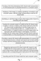
- the computer system 32 is configured for enabling the user to interact with images displayed in the display 33, and comprises an input device 40 configured for enabling the user to point to displayed objects on the display, and/or to interact with the display 33 to at least enable deletion and/or replacement of images thereon, as will become clearer below.
- the input device 40 may comprise, for example, a wand 34 (for example a light sensitive wand, or light pen) and/or a mouse 35, and/or the display 33 may incorporate the input device, being configured as a touch sensitive screen configured for at least enabling deletion and/or replacement of images thereon wherever a displayed image on the screen is touched or stroked by the user.
- color data of the intraoral cavity may also provided together with the 3D data, and thus the virtual model comprises coordinates and corresponding color information of the dental surfaces scanned.
- scanners are disclosed in co-pending application entitled “METHOD AND APPARATUS FOR COLOUR IMAGING A THREE-DIMENSIONAL STRUCTURE", published under US 2006-0001739 , and which is assigned to the present Assignee.
- At least one embodiment of such a scanner comprises a device configured for determining the surface topology and associated color of at least a portion of a three dimensional structure, such as the intra oral cavity for example, comprising:
- Such scanning means (a) may comprise the at least one embodiment of the apparatus disclosed in disclosed in WO 00/08415 and for example as defined above in connection therewith.
- the clinic 22 may include equipment for obtaining a negative casting of a patient's teeth.
- the negative cast or impression can be taken of the patient's teeth, in a manner known in the art, and this physical negative model is dispatched to one of the dental labs 26 that is equipped to prepare from the negative model a physical positive cast suitable for scanning.
- the positive cast may be scanned at the dental lab 26 by any method known in the art, including for example x-ray scanning, laser scanning or using the aforesaid probe manufactured under the name of CB-CAD or as disclosed in WO 00/08415 and referred to above.
- the 3D data is then transmitted over the network 24 to the service center 23.
- the positive cast may be dispatched to the service center 23 by the dental clinic 22 and scanned at the service center 23 to obtain the 3D data.
- the service center 23 produces a positive model from the negative model and is scanned thereat, or sent to the dental clinic 22 to be scanned thereat.
- the negative model is scanned, either at the dental lab 26 or at the service center 23.
- the negative model provided by the clinic 22 is sent to the service center 23, either directly by the clinic 22, or indirectly via the dental lab 26, and a composite physical positive-negative model may be manufactured from the original negative model. Thereafter, the positive-negative model may be processed to obtain 3D digitized data, for example as disclosed in US 6,099,314 , assigned to the present Assignee
- the 3D first virtual model VM1 may be obtained in any other suitable manner, including other suitable intra oral scanning techniques, based on optical methods, direct contact or any other means, applied directly to the patient's dentition.
- suitable intra oral scanning techniques based on optical methods, direct contact or any other means, applied directly to the patient's dentition.
- X-ray based, CT based, MRI based, or any other type of scanning of the patient or of a positive and/or negative model of the intra-oral cavity may be used.
- the dimensional data of the respective virtual model may be associated with a complete dentition, or of a partial dentition, for example such as a preparation only of the intra oral cavity.
- the virtual model VM1 is input to suitable computer system 32, and the next steps 420 to 470, are performed with the aid of computer system 32.
- the scanner 31 provides raw data to the computer system 32 which then generates the first virtual model VM1 therein from this raw data.
- step 420 the first virtual model VM1 is displayed (and optionally magnified and/or manipulated) in display 33 as a first display image DI1 corresponding to the first virtual model VM1 .
- the display 33 can be a 2D display such as conventional 2D display screen, and thus the images are 2D images.
- the display can be a 3D display and the images are also 3D images.
- the display can be a 2D stereoscopic display and the images are also 2D stereoscopic images.
- the first virtual model VM1 can then be checked visually by the user via the image DI1 on the display 33.
- This image DI1 can be virtually manipulated on the display 33 with respect to up to six degrees of freedom (i.e., translated and/or rotated with respect to one or more of three mutually orthogonal axes) by suitably manipulating the first virtual model VM1 within the computer environment of system 32, using suitable user controls (hardware and/or virtual) to enable viewing the first virtual model VM1 from any desired direction on the screen 33 via the corresponding display image DI1 on the display 33, enabling the first virtual model VM1 to be visually checked by the user.
- steps 430 to 470 are implemented when part of the first virtual model VM1, desi gnated DVM1 , is considered to be unsuitable or undesired, while concurrently it is desired to retain another part of the first virtual model VM1 .
- this part DVM1 of the first virtual model VM1 may be considered by the user as not acceptable or desirable and needing to be better defined for a particular dental procedure of interest.
- the part DVM1 can correspond, for example, to a part of a real dental surface DRM1 of the real (physical) part RM1 of the intra-oral cavity that was not sufficiently clearly defined in the first virtual model VM1.
- the corresponding part DRM1 of the physical dental surface was covered with foreign material, such as for example saliva, blood, debris, or was otherwise obscured by another element such as for example part of the gums, cheek, tongue, dental instruments, artifacts, etc.
- the virtual part DVM1 may be distorted or otherwise defective and does not properly correspond to real part DRM1 , for example due to some defect in the actual scanning process, while the real part DRM1 itself is acceptable.
- this part DVM1 of the first virtual model VM1 is marked on the first image of the first virtual model VM1 on the display 33.
- marked it is meant that this zone or area of the first image DI1 is at least identified by the user, and may optionally include interacting with the display 33 so that a visual mark is included in the image to show and demarcate this area on the image DI1 that is on the display 33.
- wand 34 operatively connected to the computer system 32 can be used for interacting with the display 33, wherein a visual mark is displayed wherever the tip 39 of the wand 34 touches the image DI1 on the display 33.
- step 440 part DVM1 of the first virtual model VM1 is then "deleted" or otherwise removed or replaced interactively on the display 33 by the user, resulting in the first virtual model VM1 being modified to become a modified first virtual model VM1', by passing the tip of the wand 34 over the marked area of the image DI1.
- the deletion, removal or replacement of part DVM1 is responsive to the application of a special corresponding computer-implemented function (i.e. a corresponding deletion function, removal function or replacement function) via the computer system 32.
- the special computer-implemented function is, for ease of reference referred to herein as the "delete” function (and includes at least one of a remove function, remove command, delete command, replace command, or replace function) of the computer system 32, and operates to modify for example the first virtual model VM1 by at least one of deleting, removing or replacing a part thereof when "delete" function is activated, i.e., when the "delete” function is applied to the marked area of the image DI1.
- the computer system 32 is configured for causing at least the deletion and/or removal and/or replacement of data corresponding to part DVM1 of the first virtual model VM1, when a corresponding part of the display image DI1 on the display 33 is correspondingly deleted or removed or replaced on the display 33, which in turn is accomplished by interaction by the user, such as touching the desired parts of the image DI1 on the display 33 with the wand 34 when the "delete" function is activated.
- the display image DI1 is a two dimensional image
- each element or pixel of such a 2D display image DI1 corresponds to a unique part of the three-dimensional data of the first virtual model VM1, as viewed in a viewing direction corresponding to image DI1
- the computer system is configured for deleting or removing or replacing such parts of the three-dimensional data from the first virtual model VM1 when the corresponding elements or pixels in the image DI1 are "touched" on the display 33 and the computer system 32 has the special "delete” function activated.
- first virtual model VM1 represents a three dimensional surface of the physical part RM1
- deleted or removed or replaced portions of the first virtual model VM1 are also three dimensional surfaces.
- the above interaction for deletion or removal with respect to image DI1 can alternatively be accomplished without recourse to touching the display 33.
- the computer system may be additionally or alternatively configured for enabling parts of the image DI1 to be deleted or removed by interaction therewith via mouse 35 or any other suitable input device 40.
- the first virtual model VM1 is thus modified by the loss of the three dimensional data corresponding to part DVM1, effectively generating a modified first 3D virtual model VM1'.
- the dental procedure of interest may be providing a dental prosthesis
- the deleted or removed part DVM1 may be part of the finish line 550 of a preparation 555 that exists in real dental surface DRM1, but failed to be represented at all, or to be clearly represented, in the first virtual model VM1, for example due to obfuscation thereof by foreign material, distortion of the scanned data, etc, as discussed above, for example.
- the dental surface DRM1 is thus considered the "first physical portion" of step 440.
- a second virtual model VM2 is created, representing a second part RM2 of the physical dental structure.
- the second virtual model VM2 comprises a virtual part DVM2 that represents the part DRM1 of the physical dental surface, plus additional identifying surface data ID that represents a part P2 of the real dental surface in proximity to part DRM1, and thus second part RM2 at least partially overlaps with the physical part RM1.
- the part DRM1 of the physical dental surface is cleaned up and/or unobstructed, and for example rescanned to obtain second virtual model VM2.
- the scanning procedure thus also includes scanning the additional part P2 the real dental surface surrounding the part DRM1 to obtain additional identifying 3D surface data ID.
- step 450 for example the virtual part DVM1 may be distorted or otherwise defective and does not properly correspond to real part DRM1, for example due to some defect in the actual scanning process thereof, while the real part DRM1 itself is acceptable.
- second virtual model VM2 is created, representing a second part RM2 of the physical dental structure, and likewise the second virtual model VM2 comprises a virtual part DVM2 that represents the same part DRM1 of the physical dental surface, plus additional identifying surface data ID that represents a part P2 of the real dental surface in proximity to part DRM1, and thus second part RM2 at least partially overlaps with the physical part RM1. While scanning to provide the second virtual model VM2, it is now ensured that second virtual model VM2 is free from distortions or imperfections that originate from the scanning procedure itself.
- the second 3D virtual model VM2 is spatially registered with respect to the modified first 3D virtual model VM1' to provide a composite third 3D virtual model VM3, wherein the part DVM1 that was previously deleted/removed is at least partially replaced with a corresponding part the second 3D virtual model VM2.
- the second virtual model VM2 is manipulated in the computer system 32 to register the second virtual model VM2 onto the modified first virtual model VM1' .
- the identifying surface data ID of second virtual model VM2 may be useful as it may be aligned with corresponding parts of the modified first virtual model VM1' , since the surface data for part P2 of the real physical dental surface should be nominally identical in both scans.
- part DVM2 of the second virtual model VM2 fits in and corresponds to at least a portion of the deleted portion DVM1, and part DVM2 is then stitched to modified first virtual model VM1' in a virtual manner to create a further modified first virtual model, i.e., composite third 3D virtual model VM3.
- the remainder of the second virtual model VM2, including the identifying surface data ID may then be discarded.
- second part RM2 at least partially overlaps with the physical part RM1, and instead the 3D data defining each respective virtual model can be referred to the same global coordinate system in a different manner, for example via an optical marker whose 3D coordinates are known with respect to a global coordinate system, and which is scanned together with each one of second part RM2 and physical part RM1.
- the composite third 3D virtual model VM3 replaces the undesired part DVM1 of the original virtual model VM1 with new 3D data provided by part DVM2.
- steps 430 to 460 may be implemented in a different manner.
- steps 430 to 460 may be replaced with steps 430' to 460' of modified method 400', which can include steps 410', 420' and 470' which are respectively identical to steps 410, 420, 470 of method 400 as disclosed herein, mutatis mutandis.
- Step 430' comprises all the elements and features of step 450 as disclosed herein, mutatis mutandis, with the main difference that step 430' is implemented immediately following step 420'.
- the second virtual model VM2 is created, representing a second part RM2 of the physical dental structure.
- the second virtual model VM2 comprises a virtual part DVM2 that represents the part DRM1 of the physical dental surface, plus additional identifying surface data ID that represents a part P2 of the real dental surface in proximity to part DRM1, and thus second part RM2 at least partially overlaps with the physical part RM1.
- the part DRM1 of the physical dental surface is cleaned up and/or unobstructed, and for example rescanned to obtain second virtual model VM2.
- the scanning procedure thus also includes scanning the additional part P2 the real dental surface surrounding the part DRM1 to obtain additional identifying 3D surface data ID.
- second virtual model VM2 is virtually registered with the first virtual model VM1.
- the second virtual model VM2 is manipulated in the computer system 32 to register the second virtual model VM2 onto the first virtual model VM1.
- the identifying surface data ID of second virtual model VM2 may be useful as it may be aligned with corresponding parts of the first virtual model VM1, since the surface data for part P2 of the real physical dental surface should be nominally identical in both scans.
- part DVM2 of the second virtual model VM2 corresponds to, in particular spatially corresponds to, and is different from, in particular is topographically different from, at least a portion of the portion DVM1 of the first virtual model VM1 (as is the case also in steps 430 to 460 of method 400, mutatis mutandis).
- portion DVM1 has not yet been deleted, removed or identified.
- the second virtual model VM2 is also displayed (and optionally magnified and/or manipulated) in display 33 as a second display image DI2 corresponding to the second virtual model VM2, wherein display image DI2 is similar to first display image DI1 as disclosed herein, mutatis mutandis, but corresponds to the second virtual model VM2 rather than the first virtual model VM1.
- the second display image DI2 is also a two-dimensional image, but in 3D displays the second display image DI2 can be a 3D image as well, or in 2D stereoscopic displays the second display image DI2 can be a 2D stereoscopic image as well for example.
- Both the second virtual model VM2 and the first virtual model VM1 are viewable on the display 33 via their respective images DI2 and DI1, either together in registry, or may be selectively viewed separately, in different display windows on the same display 33, for example, or alternately on the same display, or in different displays, and so on.
- the images DI2 and DI1 may be visually encoded, each in a different manner.
- the images DI2 and DI1 may be encoded each in a different color or shade of gray.
- at least parts of the images DI2 and DI1 which do not exactly correspond to one another may be color encoded in this manner to highlight the corresponding topographical differences between the real first part RM1 and the real second part RM2 of the physical dental structure.
- step 450' part DVM1 of the first virtual model VM1 is marked by the user on the first image of the first virtual model VM1 on the display 33, this part DVM1 having first been visually identified by the user from the images DI1 and DI2 displayed in step 440'.
- step 450' is similar to step 430 as disclosed herein, mutatis mutandis, and thus by “marked” it is meant that the user may optionally interact with this area of the first image DI1 in the display 33 so that a visual mark is included in the image to show and demarcate this area on the image DI1 that is on the display 33.
- wand 34 operatively connected to the computer system 32 can be used for interacting with the display 33, wherein a visual mark is displayed wherever the tip 39 of the wand 34 touches the image DI1 on the display 33.
- Step 460' is similar to step 440 as disclosed herein, mutatis mutandis, and thus part DVM1 of the first virtual model VM1 is then "deleted" or otherwise removed or replaced interactively on the display 33 by the user, resulting in the first virtual model VM1 being modified to become a modified first virtual model VM1', for example by passing the tip of the wand 34 over the marked area of the image DI1, when a special "delete" function (also referred to interchangeably herein as a remove function, remove command, or deleted command, or replace function, or replace command) of the computer system 32 is activated, i.e., when a corresponding function (delete function or remove function or replace function) is applied to the marked area of the image DI1.
- a special "delete” function also referred to interchangeably herein as a remove function, remove command, or deleted command, or replace function, or replace command
- Step 460' in addition comprises part of step 460 as disclosed herein, mutatis mutandis, and, with the second 3D virtual model VM2 already registered with respect to the modified first 3D virtual model VM1 (step 440'), the part DVM1 that was previously deleted/removed is at least partially replaced with a corresponding part of the second 3D virtual model VM2.
- this function operates as a unified replacement function in which DVM1 is replaced in one operation with part DVM2.
- part DVM2 of the second virtual model VM2 virtually fits in and corresponds to at least a portion of the deleted portion DVM1, and part DVM2 is then stitched to modified first virtual model VM1' in a virtual manner to create a further modified first virtual model, i.e., composite third 3D virtual model VM3.
- the remainder of the second virtual model VM2, including the identifying surface data ID may then be discarded.
- a composite third 3D virtual model VM3 (comprising modified first virtual model VM1' part DVM2) effectively replaces the undesired part DVM1 of the original virtual model VM1 with new 3D data provided by part DVM2.
- step 420' and/or step 440' can be omitted.
- the user can scan the first physical part of the structure in step 410' and then without displaying the respective first 3D virtual model, proceed with scanning the second part of the physical structure in step 430' to provide the second 3D virtual model, also without displaying the respective second 3D virtual model.
- step 460' can be implemented automatically and the first 3D virtual model replaces parts thereof with the second 3D virtual model, without the need to have these parts or the first 3D virtual model or the second 3D virtual model displayed, identified or marked.
- a situation may arise, for example, where the user suspects or knows (for example during or after scanning to provide the first 3D virtual model) that some portions of the scanned first part of the physical structure were for example obscured, ill-defined, badly scanned, and so on and need to be rescanned. The user can then go back to these portions of the physical structure and rescan those portions to provide the second 3D virtual model which then automatically replaces corresponding parts of the first 3D virtual model.
- step 420 can be omitted, and steps 440 and 460 can be modified so that the interaction with the display is omitted, and the first 3D virtual model replaces parts thereof with the second 3D virtual model automatically via registration therewith, rather than implementing a delete function first, and a stitching function later.
- a second embodiment of the invention has all the elements, features and steps of the first embodiment including steps 410 to 470 or alternative variations thereof, for example steps 410' to 470', mutatis mutandis, the main difference being that in the second embodiment the physical part RM1 of the intra-oral cavity includes a removable physical artifact which may be temporarily obscuring part of the dental surfaces.
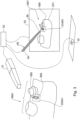
- the artifact may be a scanning body or impression abutment 600 (or any other structure) that is mounted onto a dental implant and projects into the intra oral cavity so that the spatial orientation and/or other characteristics of the implant 620 (which is already anchored in the jaw 630 and thus cannot be seen) with respect to the dental surfaces may be derived from the position/orientation of the artifact 600.
- the first virtual model VM1 for this embodiment thus also includes a virtual representation of the artifact 600, as well as all the other dental areas of interest of the physical part RM1, but the presence of the artifact 600 may render it difficult or impossible to obtain at the same time a full scan of the physical part RM1, as the artifact 600 may be too close in parts to the dental surfaces (e.g. adjacent teeth 640, 650) and thus obscures or blocks the ability of a scanner to scan such areas.
- the dental surfaces e.g. adjacent teeth 640, 650
- each part of the virtual model corresponding to an obscured area (and possibly also corresponding to the artifact 600) is deleted interactively in a similar manner that disclosed above for the first embodiment, mutatis mutandis, to provide the corresponding modified first virtual model VM1' .
- step 440 the artifact 600, which is considered the "first physical portion" in step 440, is physically removed from the intraoral cavity and an area of the physical part RM1 including the previously obscured areas that were not fully defined previously in the first virtual model VM1 is scanned, in the absence of the artifact, enabling full definition of this area to be achieved in the corresponding second virtual model VM2 thereby generated.
- step 460 second virtual model VM2 is registered with the modified first virtual model VM1', in a manner similar to that disclosed above for the first embodiment, mutatis mutandis, to provide the corresponding the corresponding composite third virtual model VM3.
- the artifact 600 itself may also be scanned separately to obtain a virtual model thereof. This may be used to further modify the composite third virtual model, if for example part of the artifact was deleted in step 440.
- Method 400' may be applied in a corresponding manner to the second embodiment, mutatis mutandis.
- a third embodiment of the invention has all the elements, features and steps of the first embodiment including steps 410 to 470 or alternative variations thereof, for example steps 410' to 470', mutatis mutandis, the main difference being that the physical part RM1 in the third embodiment is considered to be well defined in the first virtual model VM1, i.e., faithfully represents the surfaces of interest of the physical part RM1; however, a first physical portion of the physical part RM1 is not considered suitable for a dental procedure.
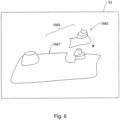
- the physical part RM1 may be a dental preparation 700 for a dental prosthesis (e.g. a crown), and analysis of the first dental model with respect to a virtual model of the opposing dentition of the opposite jaw reveals that the form of the preparation would result in an inadequate structure for the prosthesis.
- the dental preparation is too long and/or too thick, and would result in the thickness of the crown at the cusp being too thin, and thus mechanically weak.
- the distances between the preparation 700 and the opposed dental surfaces may be determined, for example, in a manner as disclosed in US 6,334,853 , which in turn can provide a measure of the corresponding thickness of the respective dental prosthesis.
- a method for obtaining a dental occlusion map of a three-dimensional virtual computer model of teeth of upper and lower jaws of a mouth, said occlusion map indicative of distances between opposite regions on facing surfaces of opposite teeth of the upper and lower jaws of the mouth comprising the steps of:
- the part of the first 3D virtual model that corresponds to the unsuitable portion of the dental preparation 700 is then deleted or removed or replaced in steps 430 and 440 in applying method 400 to this embodiment, in a manner similar to that disclosed above for the first embodiment, mutatis mutandis.
- the real dental preparation 700 is also physically modified by the dental practitioner in the areas found to be unsuitable for the prosthesis, for example via a material removal operation such as by using dental drills or dental lasers, for example, to provide a modified physical preparation 700'.
- a second virtual model VM2 corresponding to the modified preparation 700' is obtained, for example by scanning the newly worked area of the modified preparation 700', but also including additional part 750 of the preparation that was not altered in the material removal; process.
- step 460 second virtual model VM2 is registered with the modified first virtual model VM1', in a manner similar to that disclosed above for the first embodiment, mutatis mutandis, to provide the corresponding the corresponding composite third virtual model VM3.
- a new cycle of checking and modifying the preparation can be initiated if desired or necessary, wherein the third virtual model previously generated can be considered to be a "first virtual model" for the new cycle, and checked as in step 420, mutatis mutandis, and if necessary, steps 430 to 460 repeated as often as required, each time providing a new third virtual model than can be considered, if desired as a new first virtual model, until the newly modified third virtual model has a geometry for the dental preparation (corresponding to the geometry of the real dental preparation) that is adequate for receiving a prosthesis, according to criteria.
- Method 400' may be applied in a corresponding manner to the third embodiment, mutatis mutandis.
- this embodiment of the invention allows the dental practitioner to modify a dental structure such as dental preparation in a quick and easy manner with a minimum of scanning after the initial virtual scan. i.e., without the need to rescan the whole physical part RM1 again each time.
- the method (and corresponding system) according to each of the first, second and third embodiments and/or alternative variations thereof may further comprise a manufacturing step, in which a dental object may be manufactured based on the respective composite third 3D virtual model VM3 under computer aided manufacture (CAM).
- a dental object may be manufactured, for example, based on a material removal operation that is performed by a computer aided removal operation machine having a suitable machining tool, using any suitable CAM (Computer Aided Manufacturing) technology, typically a CNC milling machine, on a blank of material.
- CAM Computer Aided Manufacturing
- This material is typically plaster or any other type of material commonly used for dental models, however any other suitable material may be used.
- CAM-based techniques may be used, for example rapid prototyping or any other suitable 3D printing technique, for creating the dental object. Accordingly, a dental object corresponding to composite third 3D virtual model VM3 or associated with the composite third 3D virtual model VM3 can be manufactured.
- the dental object may comprise a physical model of the intraoral cavity, and thus composite third 3D virtual model VM3 can be used directly to provide the necessary data for the CAM process.
- the composite third 3D virtual model VM3 is based on one or more teeth requiring a prosthesis, and thus comprise a suitable preparation.
- a dental object in the form of the respective prosthesis may be prepared based on information from the composite third 3D virtual model VM3.
- the dentist or a technician may generate a 3D virtual prosthesis model of a crown to be fitted on a tooth stump (or of a bridge to be fitted on the tooth surface, or of any other prosthesis to be fitted to the tooth/teeth including any restoration and/or any onlays, and/or any inlays, such as caps, for example, or veneering, or any other artificial partial or complete denture), to generate a digital file.
- the outer surface of the prosthesis may be designed manually if desired.
- the prosthesis may then be manufactured using any suitable CAM techniques, for example as disclosed above, mutatis mutandis, and in a further step, the prosthesis may be installed in the oral cavity of the patient.
- the virtual prosthesis model may also include a virtual model of a coping plus a virtual model of a cap that is to be mounted onto the coping.
- the coping may be manufactured using any suitable method, for example as disclosed in WO 2004/087000 , also assigned to the present Assignee.
- the cap or full prosthesis may be manufactured using any suitable method, for example as disclosed in USSN 11/046,709 or in US Provisional Application No. 60/632.350 , also assigned to the present Assignee.
- a set of aligners may be manufactured based on the composite third 3D virtual model VM3.
- the teeth shown in the 3D virtual model which normally would be of a patient's teeth in their initial positions, can be segmented (i.e. digitally cut into separate objects).
- the resultant digital data can then be used for orthodontic treatment planning.
- the individual teeth can be moved by a computer program and/or by an operator into a desired final setup. Then a number of digital intermediate tooth arrangements can be generated.
- These digital intermediate and final tooth arrangements of the treatment plan can be used to fabricate positive molds of intermediate arrangements (such as by using rapid prototyping equipment or milling machines) which are used to form aligners for moving teeth or they can be used to directly form aligners
- dental objects in the form of a set of orthodontic appliances may be virtually designed and/or manufactured (for example using suitable CAM-based techniques) based on the composite third 3D virtual model VM3.
- such an orthodontic treatment may be designed using a computer system based on third 3D virtual model VM3.
- an orthodontic treatment may be provided by implementing a method for virtual orthodontic treatment, for example as disclosed in US 6,739,869 , also assigned to the present Assignee, and at least one embodiment of such a method for virtual orthodontic treatment comprises:
- the method (and corresponding system) may be applied to obtaining a 3D virtual model of any physical structure, including non-dental structures, and in which it may be desired or necessary to re-scan a part of the structure, without the need to rescan the whole structure again to obtain an updated 3D virtual model of the physical structure.
- Such method (and corresponding system) may optionally be further used for manufacturing a physical object based on or associated with the updated 3D virtual model of the physical structure.
- the method (and corresponding system) according to at least one embodiment of the invention may be applied to scanning a complex circuit board comprising a plurality of chips mounted thereon, replacing one such ship and scanning the new chip in situ, and modifying the original 3D virtual model to replace the part thereof corresponding to the old chip with the 3D data corresponding to the new chip.
- the method (and corresponding system) may be applied to scanning a complex geometrical physical structure comprising a plurality of geometrical entities mounted or formed thereon, adding or removing a geometrical physical entity with respect to the structure, and scanning the modified physical structure in the area that includes the new geometrical entity or that includes the modification of the physical structure arising from the removal of the geometrical entity, respectively, and modifying the original 3D virtual model to replace a corresponding part thereof with the 3D data corresponding to the aforesaid scanned area.
Landscapes
- Health & Medical Sciences (AREA)
- Engineering & Computer Science (AREA)
- Life Sciences & Earth Sciences (AREA)
- Physics & Mathematics (AREA)
- General Health & Medical Sciences (AREA)
- Veterinary Medicine (AREA)
- Public Health (AREA)
- Animal Behavior & Ethology (AREA)
- Oral & Maxillofacial Surgery (AREA)
- Dentistry (AREA)
- Theoretical Computer Science (AREA)
- General Engineering & Computer Science (AREA)
- Epidemiology (AREA)
- General Physics & Mathematics (AREA)
- Medical Informatics (AREA)
- Computer Hardware Design (AREA)
- Surgery (AREA)
- Molecular Biology (AREA)
- Pathology (AREA)
- Heart & Thoracic Surgery (AREA)
- Biomedical Technology (AREA)
- Biophysics (AREA)
- Software Systems (AREA)
- Nuclear Medicine, Radiotherapy & Molecular Imaging (AREA)
- Radiology & Medical Imaging (AREA)
- Computer Graphics (AREA)
- Evolutionary Computation (AREA)
- Geometry (AREA)
- Optics & Photonics (AREA)
- Architecture (AREA)
- Physical Education & Sports Medicine (AREA)
- Orthopedic Medicine & Surgery (AREA)
- Rheumatology (AREA)
- Audiology, Speech & Language Pathology (AREA)
- Quality & Reliability (AREA)
- Computer Vision & Pattern Recognition (AREA)
- Dental Tools And Instruments Or Auxiliary Dental Instruments (AREA)
- Processing Or Creating Images (AREA)
Description
- This invention relates to computer based methods and systems, particularly to computer based methods and systems that are useful in dentistry and other fields, and that are particularly useful in prosthodontics and/or orthodontics in particular.
- There are many procedures associated with the intra oral cavity in which a precise three-dimensional virtual representation of the intra oral cavity can be useful to the dental practitioner.
- Such virtual representations (also referred to interchangeably herein as "virtual models", "computer models", "3D numerical entities", and so on) enable the practitioner to study the intra oral cavity of individual patients via a computer system, in a similar manner to the study of the traditional physical plaster model. Furthermore, three-dimensional numerical entities of the intra oral cavity also allow the practitioner to study methods or approaches when dealing with particular dental problems of any given patient, and for the design of physical entities, for example prostheses, dental brackets, aligners and so on, in relation therewith. For example, in prosthodontics, a computer model of a patient's teeth may be manipulated to provide machining data to manufacture a physical model of the intra oral cavity, and/or to design and manufacture a coping and/or a prosthesis, while in orthodontics a computer model of a patient's teeth may be manipulated to enable a dental appliance, including for example orthodontic brackets and/or aligners, to be designed and manufactured, and/or for designing a treatment.
- A parameter used in the design and manufacture of a dental prosthesis, such as a crown or bridge, is the finish line, or transition boundary between the prosthesis and the dental preparation, and this needs to be precisely defined in three-dimensions. Obtaining finish line coordinates from a computer virtual model is more efficient and often more accurate than from a plaster cast, and moreover facilitates the production of such a prosthesis, for example via CNC machining, rapid prototyping, or other computerised technologies, if desired.
- However, it is often the case that when scanning the intra oral cavity to obtain 3D data of the preparation and finish line, on which the virtual model is based, part of the finish line, and possibly also the shoulder and other parts of the preparation, may be obscured by soft tissues such as the gum that, no longer being supported by the dental surfaces that have been removed, deform to cover at least a part of the finish line on the prepared dental site.
- Additionally or alternatively, part or all of the finish line may be obscured by other agents or materials, including, for example, accumulation of one or more of saliva, blood, lubricant used with a dental drill, debris resulting from working the dental site, and so on.
- Similar issues may arise when scanning the intra oral cavity to obtain 3D data of the position and orientation of a dental implant in relation to the surrounding portions of the intra-oral cavity, and in addition the corresponding impression abutment (also referred to herein as a scanning body) may partially obscure part of the intra-oral cavity.
- Similarly, there are other situations in which a virtual model of a physical item, obtained from scanning the physical item, is partially obscured or incomplete, or in which part of the physical item needs to be subsequently modified after obtaining the virtual model. Such situations would conventionally require a rescanning of the entire physical item, and this may involve significant additional time, inconvenience and, where the physical item is a part of the body of a patient (such as for example the intra oral cavity), this may also involve significant patient discomfort.
US2010/114351 discloses a 3D virtual model of an intra oral cavity in which at least a part of a finish line of a preparation is obscured is manipulated in virtual space by means of a computer or the like to create, recreate or reconstruct finish line data and other geometrical corresponding to the obscured part. Trimmed virtual models, and trimmed physical models, can then be created utilizing data thus created. The virtual models and/or the physical models may be used in the design and manufacture of copings or of prostheses. - Herein "intra oral cavity" (also referred to interchangeably herein as dental cavity) is taken to include, but not be limited to, one or more real teeth and/or one or more prosthetic teeth and/or part of one or more real teeth, of one jaw or of both jaws of 30 a patient, and/or can also include all the real teeth and/or prosthetic teeth in one or both jaws, and/or adjacent gingiva and other adjacent objects of the patient.
- Herein, "dental material" refers to any material associated with dental structures of the intra oral cavity, including but not limited to natural dental materials such as for example enamel, dentine, pulp, dental roots, and also including non-natural dental materials from which items such as for example metallic and non-metallic fillings, restorations, crowns, bridges, copings, preparations, and so on, are made from.
- Herein, "dental clinic" refers to the interface between a dental practitioner and a patent, and thus includes any physical entity, in particular a clinic, in which there is interaction between a dental patient and a dental practitioner. While "dental practitioner" typically refers to a dentist, doctor or dental technician, it also includes herein all other caregivers, including for example dental surgeons, orthodontists, prosthodontists, dental assistants or any other caregiver or professional that may interact with a dental patient during the course of a dental treatment, or that may be involved in determining, preparing or providing dental treatment to a patient, particularly prosthodontic treatment and/or orthodontic treatment. While "dental patient" (also referred to interchangeably herein as "patient") typically refers to a person requiring the dental services of a dental practitioner, it also includes herein any person regarding whom it is desired to create a 3D numerical model of the intra oral cavity thereof, for example for the purpose of practicing the same or for carrying out research.
- The term "prosthesis" is herein taken to include any restoration and any onlays, such as crowns and bridges, for example, and inlays, such as caps, for example, or veneering, or any other artificial partial or complete denture.
- The term "virtual", applied herein with respect to models, manipulation of models, and so on, in particular 3D virtual models, for example, refers to being created, simulated, manipulated, carried out, and so on by means of a CAD/CAM system, a computer, a computer network, or the like, i.e., in a computer environment, particularly with reference to digital dentistry.
- While the term "preparation" typically refers to the stump and including the finish line and shoulder that is left of the tooth that is to be replaced by the prosthesis - typically a crown - and on which the crown or other prosthesis is to be mounted or seated, the term "preparation" herein also includes artificial stumps, pivots, cores and posts, or other devices that may be implanted in the intraoral cavity in such a position or in a position that is optimal for implanting the crown or other prosthesis.
- The term "prosthodontic procedure" refers, inter alia, to any procedure involving the intraoral cavity and directed to the design, manufacture or installation of a dental prosthesis at a dental site within the intraoral cavity, or a real or virtual model thereof, or directed to the design and preparation of the dental site to receive such a prosthesis.
- The term "3D virtual model" is used herein synonymously with digital model, virtual model, 3D virtual model, 3D model, three dimensional model, 3D numerical entity, numerical entity, computer model, 3D computer model, dimensional data, 3D digitized data, 3D representation, and other such terms, and relates to a virtual representation in a computer environment of a real object, such as for example a dentition or at least a part of the intraoral cavity, or of a real (physical) model thereof, for example of a plaster model or a stone model of the dentition or any dental structure. In particular a virtual dental model is one example of such a 3D virtual model of a dental structure.
- The term "physical part" is used herein, synonymously with "real part" to refer to a physical object, in particular a physical dental object having a real (physical) surface and included but not limited to part or all of the dentition of the intraoral cavity including dies, a coping, a prosthesis, and so on, or to a physical dental model of part or all of the dentition of the intraoral cavity including dies, a coping, a prosthesis, and so on.
- The term "scanning" and its analogues refer to any procedure directed at obtaining 3D topographic data of a surface, particularly of a dental surface, wherein to provide a 3D virtual model, and thus includes mechanical-based or other contact systems and methods, typically based on 3D probes for example, and/or any other noncontact systems and methods included but not limited to optical-based systems and methods and/or radiation-based systems and methods, including for example confocal-based systems and methods, for example as disclosed in
WO 00/08415
x-ray systems and methods including CT systems and methods, laser scanners, ultrasound scanners, and/or indeed any other suitable system and method for providing 3D virtual model. - The terms "tool" and "machining tool" are taken herein interchangeably to include any tool that is adapted for material removal, and may include inter alia mechanical tools such as drills for example, laser tools such as for example laser drills or cutters, ultrasonic tools such as for example ultrasonic cutters, and so on. Preferably, the machining paths and material removal characteristics of such tools can be finely controlled, typically by computer systems or other automated means.
- According to a first aspect of the invention there is provided a computer based a computer based method for updating a 3D virtual model of an intraoral cavity of a patient the method, as defined in independent claim 1.
- According to a second and a third aspect of the invention, there are also provided a computer program product as defined in independent claim 12, and a computer system as defined in independent claim 13.
- Embodiments of the invention are defined in the dependent claims.
- In order to understand the invention and to see how it may be carried out in practice, embodiments will now be described, by way of non-limiting example only, with reference to the accompanying drawings, in which:
-
Fig. 1 shows, by way of a flow chart, a method in accordance with a first embodiment of the invention. -
Fig. 2 shows various elements of a system used for providing and manipulating a virtual dental model according to the embodiment ofFig. 1 . -
Fig. 3 schematically illustrates providing a first virtual model to the computer system ofFig. 2 , and interacting with the display thereof. -
Fig, 4 schematically illustrated a modified first computer model as displayed by the computer system ofFig. 2 . -
Fig. 5 schematically illustrates providing a second virtual model to the computer system ofFig. 2 . -
Fig. 6 schematically illustrates manipulating the second virtual model ofFig. 5 into registration with the modified computer model ofFig. 4 . -
Fig. 7 schematically illustrates an example of physical part used in conjunction with a second embodiment of the invention. -
Fig. 8 schematically illustrates an example of physical part used in conjunction with a third embodiment of the invention. -
Fig. 9 shows, by way of a flow chart, a method in accordance with an alternative variation of the first embodiment of the invention - A computer-based method, particularly useful for creating, manipulating and refining a virtual dental model, according to a first embodiment of the invention and designated with
reference numeral 400 is illustrated inFig. 1 . - In
step 410 carried out by themethod 400, an accurate 3D representation, i.e., a first 3D virtual model of a physical structure, in this example the intraoral cavity, is obtained. This first 3D virtual model is generally designated with the numeral VM1 in the accompanying figures. As used herein, and as already discussed, the intra oral cavity can include one or more real teeth and/or one or more prosthetic teeth and/or part of one or more real teeth of one jaw or of both jaws of a patient, and/or can also include all the real teeth and/or prosthetic teeth in one or both jaws, and/or adjacent gingiva and other adjacent objects of the patient, and/or can include a physical model or other physical representation of one or more or all the real teeth, and/or one or more or all of the prosthetic teeth, and/or part of one or more or all the real teeth, of one jaw or of both jaws, and/or of adjacent gingiva and/or other adjacent objects, of the patient. - Referring also to
Fig. 3 , the first 3D virtual model VM1 is thus representative of a physical part RM1 of the intra-oral cavity (typically of a patient, in vivo, but alternatively the first 3D virtual model VM1 may be of a physical dental model, as will become clearer below) including a tooth or teeth of interest. - The first 3D virtual model VM1, i.e. the 3D digitized data of the intraoral cavity, including the dentition and associated anatomical structures of a patient, may be provided using any suitable scanning equipment for scanning a patient's teeth, for example by scanning the intra oral cavity of the patient in vivo, or via scanning of a physical model or an impression thereof. Referring to
Fig. 2 , this may be done for example at adental clinic 22 by the dentist or another dental practitioner. Thedental clinic 22 is typically linked to one or moredental labs 26, and possibly also to adental service center 23 via a communication means or network such as for example the Internet or other suitable communications medium such as an intranet, local access network, public switched telephone network, cable network, satellite communication system, and the like, indicated by the cloud at 24. Thedental lab 26 is particularly adapted for defining the finish line, as well as for other tasks such as designing prostheses, designing and manufacturing physical models of the dentition, and possibly also for manufacturing at least an external profile of the prostheses. Thedental service center 23 is particularly adapted for manufacturing dental hardware that requires a very high degree of precision, for example inner surfaces of prostheses that are required to match external surfaces of copings, and possibly also the copings themselves. - Such scanning equipment may include any suitable scanner, for example, an optical hand-held scanner 31 (or any other suitable optical scanner, mechanical scanner, ultrasound scanner, radiation-based scanner, including for example x-ray scanner, or other laser scanner, or any other suitable scanner) that is used by the practitioner to acquire the 3D data for example by directly scanning the patient's oral cavity. For example, a hand held apparatus including a probe for determining three dimensional structure by confocal focusing of an array of light beams can be used, for example as manufactured under the name of CB-CAD or as disclosed in
WO 00/08415
and in which in at least one embodiment, the apparatus is configured for determining surface topology of a portion of a three-dimensional structure, such as the intra oral cavity for example, the apparatus comprising: - a probing member with a sensing face;
- an illumination unit for providing an array of incident light beams transmitted towards the structure along an optical path through said probing unit to generate illuminated spots on said portion;
- a light focusing optics defining one or more focal planes forward said probing face at a position changeable by said optics, each light beam having its focus on one of said one or more focal plane;
- a translation mechanism for displacing said focal plane relative to the structure along an axis defined by the propagation of the incident light beams;
- a detector having an array of sensing elements for measuring intensity of each of a plurality of light beams returning from said spots propagating through an optical path opposite to that of the incident light beams;
- a processor coupled to said detector for determining for each light beam a spot-specific position, being the position of the respective focal plane of said one or more focal planes yielding maximum measured intensity of the returned light beam, and based on the determined spot-specific positions, generating data representative of the topology of said portion.
- The 3D data obtained by the
scanner 31 may then be stored in a suitable storage medium, for example a memory in a computer workstation orsystem 32, which includes adisplay 33, such as for example a computer screen, operatively connected thereto. Typically, the 3D data can be sent over asuitable communication network 24 to thedental lab 26, for further processing. Optionally, the 3D data may be sent viacommunication network 24 to thedental service center 23, for the further processing. - The
computer system 32 is configured for enabling the user to interact with images displayed in thedisplay 33, and comprises aninput device 40 configured for enabling the user to point to displayed objects on the display, and/or to interact with thedisplay 33 to at least enable deletion and/or replacement of images thereon, as will become clearer below. Theinput device 40 may comprise, for example, a wand 34 (for example a light sensitive wand, or light pen) and/or amouse 35, and/or thedisplay 33 may incorporate the input device, being configured as a touch sensitive screen configured for at least enabling deletion and/or replacement of images thereon wherever a displayed image on the screen is touched or stroked by the user. - Optionally, color data of the intraoral cavity may also provided together with the 3D data, and thus the virtual model comprises coordinates and corresponding color information of the dental surfaces scanned. Examples of such scanners are disclosed in co-pending application entitled "METHOD AND APPARATUS FOR COLOUR IMAGING A THREE-DIMENSIONAL STRUCTURE", published under
US 2006-0001739 , and which is assigned to the present Assignee. - At least one embodiment of such a scanner comprises a device configured for determining the surface topology and associated color of at least a portion of a three dimensional structure, such as the intra oral cavity for example, comprising:
- (a) scanning means adapted for providing depth data of said portion corresponding to a two-dimensional reference array substantially orthogonal to a depth direction;
- (b) imaging means adapted for providing two-dimensional color image data of said portion associated with said reference array; wherein the device is adapted for maintaining a spatial disposition with respect to said portion that is substantially fixed during operation of said scanning means and said imaging means.
- Such scanning means (a) may comprise the at least one embodiment of the apparatus disclosed in disclosed in
WO 00/08415 - Alternatively or additionally, the
clinic 22 may include equipment for obtaining a negative casting of a patient's teeth. In this case, the negative cast or impression can be taken of the patient's teeth, in a manner known in the art, and this physical negative model is dispatched to one of thedental labs 26 that is equipped to prepare from the negative model a physical positive cast suitable for scanning. The positive cast may be scanned at thedental lab 26 by any method known in the art, including for example x-ray scanning, laser scanning or using the aforesaid probe manufactured under the name of CB-CAD or as disclosed inWO 00/08415 network 24 to theservice center 23. Alternatively, the positive cast may be dispatched to theservice center 23 by thedental clinic 22 and scanned at theservice center 23 to obtain the 3D data. Alternatively, theservice center 23 produces a positive model from the negative model and is scanned thereat, or sent to thedental clinic 22 to be scanned thereat. Alternatively, the negative model is scanned, either at thedental lab 26 or at theservice center 23. - Alternatively, the negative model provided by the
clinic 22 is sent to theservice center 23, either directly by theclinic 22, or indirectly via thedental lab 26, and a composite physical positive-negative model may be manufactured from the original negative model. Thereafter, the positive-negative model may be processed to obtain 3D digitized data, for example as disclosed inUS 6,099,314 , assigned to the present Assignee - Alternatively, the 3D first virtual model VM1 may be obtained in any other suitable manner, including other suitable intra oral scanning techniques, based on optical methods, direct contact or any other means, applied directly to the patient's dentition. Alternatively, X-ray based, CT based, MRI based, or any other type of scanning of the patient or of a positive and/or negative model of the intra-oral cavity may be used. As is clear from the aforegoing, the dimensional data of the respective virtual model may be associated with a complete dentition, or of a partial dentition, for example such as a preparation only of the intra oral cavity.
- Once the 3D digitized data is obtained, the virtual model VM1 is input to
suitable computer system 32, and thenext steps 420 to 470, are performed with the aid ofcomputer system 32. In alternative variations of this embodiment, thescanner 31 provides raw data to thecomputer system 32 which then generates the first virtual model VM1 therein from this raw data. - In
step 420, the first virtual model VM1 is displayed (and optionally magnified and/or manipulated) indisplay 33 as a first display image DI1 corresponding to the first virtual model VM1. - For example, the
display 33 can be a 2D display such as conventional 2D display screen, and thus the images are 2D images. Alternatively, the display can be a 3D display and the images are also 3D images. Alternatively, the display can be a 2D stereoscopic display and the images are also 2D stereoscopic images. - The first virtual model VM1 can then be checked visually by the user via the image DI1 on the
display 33. This image DI1 can be virtually manipulated on thedisplay 33 with respect to up to six degrees of freedom (i.e., translated and/or rotated with respect to one or more of three mutually orthogonal axes) by suitably manipulating the first virtual model VM1 within the computer environment ofsystem 32, using suitable user controls (hardware and/or virtual) to enable viewing the first virtual model VM1 from any desired direction on thescreen 33 via the corresponding display image DI1 on thedisplay 33, enabling the first virtual model VM1 to be visually checked by the user. - According to this embodiment, steps 430 to 470 are implemented when part of the first virtual model VM1, desi gnated DVM1, is considered to be unsuitable or undesired, while concurrently it is desired to retain another part of the first virtual model VM1.
- For example, this part DVM1 of the first virtual model VM1 may be considered by the user as not acceptable or desirable and needing to be better defined for a particular dental procedure of interest. The part DVM1 can correspond, for example, to a part of a real dental surface DRM1 of the real (physical) part RM1 of the intra-oral cavity that was not sufficiently clearly defined in the first virtual model VM1. For example, during the initial 3D data collection step, for example via scanning, that resulted in the first virtual model VM1 being generated, the corresponding part DRM1 of the physical dental surface was covered with foreign material, such as for example saliva, blood, debris, or was otherwise obscured by another element such as for example part of the gums, cheek, tongue, dental instruments, artifacts, etc. Alternatively, for example, during the initial 3D data collection step, for example via scanning, that resulted in the first virtual model VM1 being generated, the virtual part DVM1 may be distorted or otherwise defective and does not properly correspond to real part DRM1, for example due to some defect in the actual scanning process, while the real part DRM1 itself is acceptable.
- In
step 430 this part DVM1 of the first virtual model VM1 is marked on the first image of the first virtual model VM1 on thedisplay 33. By "marked" it is meant that this zone or area of the first image DI1 is at least identified by the user, and may optionally include interacting with thedisplay 33 so that a visual mark is included in the image to show and demarcate this area on the image DI1 that is on thedisplay 33. For example,wand 34, operatively connected to thecomputer system 32 can be used for interacting with thedisplay 33, wherein a visual mark is displayed wherever thetip 39 of thewand 34 touches the image DI1 on thedisplay 33. - In
step 440, and referring also toFig. 4 , part DVM1 of the first virtual model VM1 is then "deleted" or otherwise removed or replaced interactively on thedisplay 33 by the user, resulting in the first virtual model VM1 being modified to become a modified first virtual model VM1', by passing the tip of thewand 34 over the marked area of the image DI1. The deletion, removal or replacement of part DVM1 is responsive to the application of a special corresponding computer-implemented function (i.e. a corresponding deletion function, removal function or replacement function) via thecomputer system 32. The special computer-implemented function is, for ease of reference referred to herein as the "delete" function (and includes at least one of a remove function, remove command, delete command, replace command, or replace function) of thecomputer system 32, and operates to modify for example the first virtual model VM1 by at least one of deleting, removing or replacing a part thereof when "delete" function is activated, i.e., when the "delete" function is applied to the marked area of the image DI1. - According to this special "delete" function, the
computer system 32 is configured for causing at least the deletion and/or removal and/or replacement of data corresponding to part DVM1 of the first virtual model VM1, when a corresponding part of the display image DI1 on thedisplay 33 is correspondingly deleted or removed or replaced on thedisplay 33, which in turn is accomplished by interaction by the user, such as touching the desired parts of the image DI1 on thedisplay 33 with thewand 34 when the "delete" function is activated. - Although in at least one embodiment the display image DI1 is a two dimensional image, each element or pixel of such a 2D display image DI1 corresponds to a unique part of the three-dimensional data of the first virtual model VM1, as viewed in a viewing direction corresponding to image DI1, and thus the computer system is configured for deleting or removing or replacing such parts of the three-dimensional data from the first virtual model VM1 when the corresponding elements or pixels in the image DI1 are "touched" on the
display 33 and thecomputer system 32 has the special "delete" function activated. - Particularly where the first virtual model VM1 represents a three dimensional surface of the physical part RM1, it is readily understood that the deleted or removed or replaced portions of the first virtual model VM1 are also three dimensional surfaces.
- The above interaction for deletion or removal with respect to image DI1 can alternatively be accomplished without recourse to touching the
display 33. For example, the computer system may be additionally or alternatively configured for enabling parts of the image DI1 to be deleted or removed by interaction therewith viamouse 35 or any othersuitable input device 40. - The first virtual model VM1 is thus modified by the loss of the three dimensional data corresponding to part DVM1, effectively generating a modified first 3D virtual model VM1'.
- For example, the dental procedure of interest may be providing a dental prosthesis, and the deleted or removed part DVM1 may be part of the
finish line 550 of apreparation 555 that exists in real dental surface DRM1, but failed to be represented at all, or to be clearly represented, in the first virtual model VM1, for example due to obfuscation thereof by foreign material, distortion of the scanned data, etc, as discussed above, for example. - The dental surface DRM1 is thus considered the "first physical portion" of
step 440. - In
step 450, and referring also toFig. 5 , a second virtual model VM2 is created, representing a second part RM2 of the physical dental structure. The second virtual model VM2 comprises a virtual part DVM2 that represents the part DRM1 of the physical dental surface, plus additional identifying surface data ID that represents a part P2 of the real dental surface in proximity to part DRM1, and thus second part RM2 at least partially overlaps with the physical part RM1. Before doing so, the part DRM1 of the physical dental surface is cleaned up and/or unobstructed, and for example rescanned to obtain second virtual model VM2. The scanning procedure thus also includes scanning the additional part P2 the real dental surface surrounding the part DRM1 to obtain additional identifying 3D surface data ID. - It is to be noted that in a variation of
step 450, for example the virtual part DVM1 may be distorted or otherwise defective and does not properly correspond to real part DRM1, for example due to some defect in the actual scanning process thereof, while the real part DRM1 itself is acceptable. In such a case, second virtual model VM2 is created, representing a second part RM2 of the physical dental structure, and likewise the second virtual model VM2 comprises a virtual part DVM2 that represents the same part DRM1 of the physical dental surface, plus additional identifying surface data ID that represents a part P2 of the real dental surface in proximity to part DRM1, and thus second part RM2 at least partially overlaps with the physical part RM1. While scanning to provide the second virtual model VM2, it is now ensured that second virtual model VM2 is free from distortions or imperfections that originate from the scanning procedure itself. - In
step 460, and referring also toFig. 6 , the second 3D virtual model VM2 is spatially registered with respect to the modified first 3D virtual model VM1' to provide a composite third 3D virtual model VM3, wherein the part DVM1 that was previously deleted/removed is at least partially replaced with a corresponding part the second 3D virtual model VM2. In particular, the second virtual model VM2 is manipulated in thecomputer system 32 to register the second virtual model VM2 onto the modified first virtual model VM1'. In this connection, the identifying surface data ID of second virtual model VM2 may be useful as it may be aligned with corresponding parts of the modified first virtual model VM1', since the surface data for part P2 of the real physical dental surface should be nominally identical in both scans. In this aligned position, part DVM2 of the second virtual model VM2 fits in and corresponds to at least a portion of the deleted portion DVM1, and part DVM2 is then stitched to modified first virtual model VM1' in a virtual manner to create a further modified first virtual model, i.e., composite third 3D virtual model VM3. The remainder of the second virtual model VM2, including the identifying surface data ID may then be discarded. - Alternatively, it may not be necessary that second part RM2 at least partially overlaps with the physical part RM1, and instead the 3D data defining each respective virtual model can be referred to the same global coordinate system in a different manner, for example via an optical marker whose 3D coordinates are known with respect to a global coordinate system, and which is scanned together with each one of second part RM2 and physical part RM1.
- Thus, the composite third 3D virtual model VM3 replaces the undesired part DVM1 of the original virtual model VM1 with new 3D data provided by part DVM2.
- It is readily evident that by carrying out
steps 430 to 460, the user only needs to "correct" or modify parts of the original virtual model VM1 of the dental surface i.e. of physical part RM1, and does not need to obtain a new virtual model of the whole of physical part RM1 from scratch, should even a small part of the virtual model VM1 not be acceptable. - In alternative variations of this embodiment, steps 430 to 460 may be implemented in a different manner. For example, and referring to
Fig. 9 ,steps 430 to 460 may be replaced with steps 430' to 460' of modified method 400', which can include steps 410', 420' and 470' which are respectively identical tosteps method 400 as disclosed herein, mutatis mutandis. - Step 430' comprises all the elements and features of
step 450 as disclosed herein, mutatis mutandis, with the main difference that step 430' is implemented immediately following step 420'. In other words, and having carried out steps 410' and 420', the second virtual model VM2 is created, representing a second part RM2 of the physical dental structure. Again, the second virtual model VM2 comprises a virtual part DVM2 that represents the part DRM1 of the physical dental surface, plus additional identifying surface data ID that represents a part P2 of the real dental surface in proximity to part DRM1, and thus second part RM2 at least partially overlaps with the physical part RM1. Before doing so, the part DRM1 of the physical dental surface is cleaned up and/or unobstructed, and for example rescanned to obtain second virtual model VM2. The scanning procedure thus also includes scanning the additional part P2 the real dental surface surrounding the part DRM1 to obtain additional identifying 3D surface data ID. - Then, in step 440', second virtual model VM2 is virtually registered with the first virtual model VM1. In particular, the second virtual model VM2 is manipulated in the
computer system 32 to register the second virtual model VM2 onto the first virtual model VM1. In this connection, the identifying surface data ID of second virtual model VM2 may be useful as it may be aligned with corresponding parts of the first virtual model VM1, since the surface data for part P2 of the real physical dental surface should be nominally identical in both scans. In this aligned position, part DVM2 of the second virtual model VM2, corresponds to, in particular spatially corresponds to, and is different from, in particular is topographically different from, at least a portion of the portion DVM1 of the first virtual model VM1 (as is the case also insteps 430 to 460 ofmethod 400, mutatis mutandis). At this point, portion DVM1 has not yet been deleted, removed or identified. - In step 440', the second virtual model VM2 is also displayed (and optionally magnified and/or manipulated) in
display 33 as a second display image DI2 corresponding to the second virtual model VM2, wherein display image DI2 is similar to first display image DI1 as disclosed herein, mutatis mutandis, but corresponds to the second virtual model VM2 rather than the first virtual model VM1. For example when using a 2D display, the second display image DI2 is also a two-dimensional image, but in 3D displays the second display image DI2 can be a 3D image as well, or in 2D stereoscopic displays the second display image DI2 can be a 2D stereoscopic image as well for example. - Both the second virtual model VM2 and the first virtual model VM1 are viewable on the
display 33 via their respective images DI2 and DI1, either together in registry, or may be selectively viewed separately, in different display windows on thesame display 33, for example, or alternately on the same display, or in different displays, and so on. To facilitate viewing the images in 3D registry, the images DI2 and DI1 may be visually encoded, each in a different manner. For example, the images DI2 and DI1 may be encoded each in a different color or shade of gray. Alternatively, at least parts of the images DI2 and DI1 which do not exactly correspond to one another may be color encoded in this manner to highlight the corresponding topographical differences between the real first part RM1 and the real second part RM2 of the physical dental structure. - In step 450', part DVM1 of the first virtual model VM1 is marked by the user on the first image of the first virtual model VM1 on the
display 33, this part DVM1 having first been visually identified by the user from the images DI1 and DI2 displayed in step 440'. Thus, step 450' is similar to step 430 as disclosed herein, mutatis mutandis, and thus by "marked" it is meant that the user may optionally interact with this area of the first image DI1 in thedisplay 33 so that a visual mark is included in the image to show and demarcate this area on the image DI1 that is on thedisplay 33. For example,wand 34, operatively connected to thecomputer system 32 can be used for interacting with thedisplay 33, wherein a visual mark is displayed wherever thetip 39 of thewand 34 touches the image DI1 on thedisplay 33. - Step 460' is similar to step 440 as disclosed herein, mutatis mutandis, and thus part DVM1 of the first virtual model VM1 is then "deleted" or otherwise removed or replaced interactively on the
display 33 by the user, resulting in the first virtual model VM1 being modified to become a modified first virtual model VM1', for example by passing the tip of thewand 34 over the marked area of the image DI1, when a special "delete" function (also referred to interchangeably herein as a remove function, remove command, or deleted command, or replace function, or replace command) of thecomputer system 32 is activated, i.e., when a corresponding function (delete function or remove function or replace function) is applied to the marked area of the image DI1. Step 460' in addition comprises part ofstep 460 as disclosed herein, mutatis mutandis, and, with the second 3D virtual model VM2 already registered with respect to the modified first 3D virtual model VM1 (step 440'), the part DVM1 that was previously deleted/removed is at least partially replaced with a corresponding part of the second 3D virtual model VM2. Alternatively, this function operates as a unified replacement function in which DVM1 is replaced in one operation with part DVM2. - In the aligned position of the registered modified first virtual model VM1' with second virtual model VM2, part DVM2 of the second virtual model VM2 virtually fits in and corresponds to at least a portion of the deleted portion DVM1, and part DVM2 is then stitched to modified first virtual model VM1' in a virtual manner to create a further modified first virtual model, i.e., composite third 3D virtual model VM3. The remainder of the second virtual model VM2, including the identifying surface data ID may then be discarded.
- Thus, in step 470', a composite third 3D virtual model VM3 (comprising modified first virtual model VM1' part DVM2) effectively replaces the undesired part DVM1 of the original virtual model VM1 with new 3D data provided by part DVM2.
- It is to be noted that at least in some alternative variations of the method 400', step 420' and/or step 440' can be omitted. For example, the user can scan the first physical part of the structure in step 410' and then without displaying the respective first 3D virtual model, proceed with scanning the second part of the physical structure in step 430' to provide the second 3D virtual model, also without displaying the respective second 3D virtual model. Thus, so long as the first 3D virtual model and the second 3D virtual model can be spatially registered (and thus the first physical part corresponds to (in particular spatially corresponds to) but may be different from (in particular topographically different from) the second physical part), step 460' can be implemented automatically and the first 3D virtual model replaces parts thereof with the second 3D virtual model, without the need to have these parts or the first 3D virtual model or the second 3D virtual model displayed, identified or marked. Such a situation may arise, for example, where the user suspects or knows (for example during or after scanning to provide the first 3D virtual model) that some portions of the scanned first part of the physical structure were for example obscured, ill-defined, badly scanned, and so on and need to be rescanned. The user can then go back to these portions of the physical structure and rescan those portions to provide the second 3D virtual model which then automatically replaces corresponding parts of the first 3D virtual model.
- In a similar manner, mutatis mutandis, in at least in some alternative variations of the
method 400, step 420 can be omitted, and steps 440 and 460 can be modified so that the interaction with the display is omitted, and the first 3D virtual model replaces parts thereof with the second 3D virtual model automatically via registration therewith, rather than implementing a delete function first, and a stitching function later. - Referring to
Fig. 7 , a second embodiment of the invention has all the elements, features and steps of the firstembodiment including steps 410 to 470 or alternative variations thereof, for example steps 410' to 470', mutatis mutandis, the main difference being that in the second embodiment the physical part RM1 of the intra-oral cavity includes a removable physical artifact which may be temporarily obscuring part of the dental surfaces. - For example, the artifact may be a scanning body or impression abutment 600 (or any other structure) that is mounted onto a dental implant and projects into the intra oral cavity so that the spatial orientation and/or other characteristics of the implant 620 (which is already anchored in the
jaw 630 and thus cannot be seen) with respect to the dental surfaces may be derived from the position/orientation of theartifact 600. - The first virtual model VM1 for this embodiment thus also includes a virtual representation of the
artifact 600, as well as all the other dental areas of interest of the physical part RM1, but the presence of theartifact 600 may render it difficult or impossible to obtain at the same time a full scan of the physical part RM1, as theartifact 600 may be too close in parts to the dental surfaces (e.g.adjacent teeth 640, 650) and thus obscures or blocks the ability of a scanner to scan such areas. - In this embodiment, and in applying
method 400 to this embodiment, insteps - Then, and prior to step 440, the
artifact 600, which is considered the "first physical portion" instep 440, is physically removed from the intraoral cavity and an area of the physical part RM1 including the previously obscured areas that were not fully defined previously in the first virtual model VM1 is scanned, in the absence of the artifact, enabling full definition of this area to be achieved in the corresponding second virtual model VM2 thereby generated. - Thereafter, in
step 460, second virtual model VM2 is registered with the modified first virtual model VM1', in a manner similar to that disclosed above for the first embodiment, mutatis mutandis, to provide the corresponding the corresponding composite third virtual model VM3. - If necessary or desired, the
artifact 600 itself (or part thereof) may also be scanned separately to obtain a virtual model thereof. This may be used to further modify the composite third virtual model, if for example part of the artifact was deleted instep 440. - Method 400' may be applied in a corresponding manner to the second embodiment, mutatis mutandis.
- It is readily evident that by carrying out this embodiment of the invention, it allows obtaining a virtual model of the intra oral cavity including such an artifact, wherein even the parts of the dental surfaces obscured by the artifact can be fully defined with respect thereto, even when originally obscured by the artifact.
- Referring to
Fig. 8 , a third embodiment of the invention has all the elements, features and steps of the firstembodiment including steps 410 to 470 or alternative variations thereof, for example steps 410' to 470', mutatis mutandis, the main difference being that the physical part RM1 in the third embodiment is considered to be well defined in the first virtual model VM1, i.e., faithfully represents the surfaces of interest of the physical part RM1; however, a first physical portion of the physical part RM1 is not considered suitable for a dental procedure. - For example, the physical part RM1 may be a
dental preparation 700 for a dental prosthesis (e.g. a crown), and analysis of the first dental model with respect to a virtual model of the opposing dentition of the opposite jaw reveals that the form of the preparation would result in an inadequate structure for the prosthesis. For example, the dental preparation is too long and/or too thick, and would result in the thickness of the crown at the cusp being too thin, and thus mechanically weak. - In this connection, the distances between the
preparation 700 and the opposed dental surfaces may be determined, for example, in a manner as disclosed inUS 6,334,853 , which in turn can provide a measure of the corresponding thickness of the respective dental prosthesis. In at least one embodiment disclosed inUS 6,334,853 , there is provided a method for obtaining a dental occlusion map of a three-dimensional virtual computer model of teeth of upper and lower jaws of a mouth, said occlusion map indicative of distances between opposite regions on facing surfaces of opposite teeth of the upper and lower jaws of the mouth, said method comprising the steps of: - (i) determining said distances between opposite regions on opposite teeth of the upper and lower jaws of the mouth; and
- (ii) setting up a correspondence between said determined distances and regions on a mapping surface.
- The part of the first 3D virtual model that corresponds to the unsuitable portion of the
dental preparation 700 is then deleted or removed or replaced insteps method 400 to this embodiment, in a manner similar to that disclosed above for the first embodiment, mutatis mutandis. - The real
dental preparation 700 is also physically modified by the dental practitioner in the areas found to be unsuitable for the prosthesis, for example via a material removal operation such as by using dental drills or dental lasers, for example, to provide a modified physical preparation 700'. - Thereafter, in
step 450, a second virtual model VM2 corresponding to the modified preparation 700' is obtained, for example by scanning the newly worked area of the modified preparation 700', but also includingadditional part 750 of the preparation that was not altered in the material removal; process. - In
step 460, second virtual model VM2 is registered with the modified first virtual model VM1', in a manner similar to that disclosed above for the first embodiment, mutatis mutandis, to provide the corresponding the corresponding composite third virtual model VM3. - A new cycle of checking and modifying the preparation can be initiated if desired or necessary, wherein the third virtual model previously generated can be considered to be a "first virtual model" for the new cycle, and checked as in
step 420, mutatis mutandis, and if necessary, steps 430 to 460 repeated as often as required, each time providing a new third virtual model than can be considered, if desired as a new first virtual model, until the newly modified third virtual model has a geometry for the dental preparation (corresponding to the geometry of the real dental preparation) that is adequate for receiving a prosthesis, according to criteria. - It is also readily evident that rather than modifying the whole preparation, only part of the preparation, for example a part of the finish line, can be modified instead, and the method applied to this part only, saving considerable time by not having to scan the remainder of the preparation (that is considered acceptable) or surrounding areas, i.e., the whole physical part RM1 again each time.
- Method 400' may be applied in a corresponding manner to the third embodiment, mutatis mutandis.
- It is also readily evident that by carrying out this embodiment of the invention, it allows the dental practitioner to modify a dental structure such as dental preparation in a quick and easy manner with a minimum of scanning after the initial virtual scan. i.e., without the need to rescan the whole physical part RM1 again each time.
- It also readily evident that parts or all of the method steps according to each of the first, second and third embodiments and/or alternative variations thereof may be applied to one or more of the other embodiments as well.
- It is also readily evident that the method (and corresponding system) according to each of the first, second and third embodiments and/or alternative variations thereof may further comprise a manufacturing step, in which a dental object may be manufactured based on the respective composite third 3D virtual model VM3 under computer aided manufacture (CAM). Such a dental object may be manufactured, for example, based on a material removal operation that is performed by a computer aided removal operation machine having a suitable machining tool, using any suitable CAM (Computer Aided Manufacturing) technology, typically a CNC milling machine, on a blank of material. This material is typically plaster or any other type of material commonly used for dental models, however any other suitable material may be used. Alternatively, other CAM-based techniques may be used, for example rapid prototyping or any other suitable 3D printing technique, for creating the dental object. Accordingly, a dental object corresponding to composite third 3D virtual model VM3 or associated with the composite third 3D virtual model VM3 can be manufactured.
- For example, the dental object may comprise a physical model of the intraoral cavity, and thus composite third 3D virtual model VM3 can be used directly to provide the necessary data for the CAM process.
- In another example, and where the composite third 3D virtual model VM3 is based on one or more teeth requiring a prosthesis, and thus comprise a suitable preparation. A dental object in the form of the respective prosthesis may be prepared based on information from the composite third 3D virtual model VM3. The dentist or a technician may generate a 3D virtual prosthesis model of a crown to be fitted on a tooth stump (or of a bridge to be fitted on the tooth surface, or of any other prosthesis to be fitted to the tooth/teeth including any restoration and/or any onlays, and/or any inlays, such as caps, for example, or veneering, or any other artificial partial or complete denture), to generate a digital file. Alternatively, the outer surface of the prosthesis may be designed manually if desired. The prosthesis may then be manufactured using any suitable CAM techniques, for example as disclosed above, mutatis mutandis, and in a further step, the prosthesis may be installed in the oral cavity of the patient. Optionally, the virtual prosthesis model may also include a virtual model of a coping plus a virtual model of a cap that is to be mounted onto the coping. The coping may be manufactured using any suitable method, for example as disclosed in
WO 2004/087000 , also assigned to the present Assignee. - The cap or full prosthesis may be manufactured using any suitable method, for example as disclosed in
USSN 11/046,709 or inUS Provisional Application No. 60/632.350 , also assigned to the present Assignee. - In another example, and where the composite third 3D virtual model VM3 is based on one or more teeth requiring an orthodontic treatment, a set of aligners may be manufactured based on the composite third 3D virtual model VM3. For example, the teeth shown in the 3D virtual model, which normally would be of a patient's teeth in their initial positions, can be segmented (i.e. digitally cut into separate objects). The resultant digital data can then be used for orthodontic treatment planning. The individual teeth can be moved by a computer program and/or by an operator into a desired final setup. Then a number of digital intermediate tooth arrangements can be generated. These digital intermediate and final tooth arrangements of the treatment plan can be used to fabricate positive molds of intermediate arrangements (such as by using rapid prototyping equipment or milling machines) which are used to form aligners for moving teeth or they can be used to directly form aligners
- Alternatively, where the composite third 3D virtual model VM3 is based on one or more teeth requiring an orthodontic treatment, dental objects in the form of a set of orthodontic appliances, for example brackets, may be virtually designed and/or manufactured (for example using suitable CAM-based techniques) based on the composite third 3D virtual model VM3.
- Furthermore, where the composite third 3D virtual model VM3 is based on one or more teeth requiring an orthodontic treatment, such an orthodontic treatment may be designed using a computer system based on third 3D virtual model VM3. For example such an orthodontic treatment may be provided by implementing a method for virtual orthodontic treatment, for example as disclosed in
US 6,739,869 , also assigned to the present Assignee, and at least one embodiment of such a method for virtual orthodontic treatment comprises: - (a) providing a first virtual three-dimensional (3D) image indicative of a 3D model of all teeth of at least one jaw, the model being manipulable so as to allow its viewing from a desired direction - for example such a first virtual three-dimensional (3D) image may be based on the composite third 3D virtual model VM3;
- (b) selecting a virtual set of orthodontic components, comprising (i) brackets, one for each tooth in said first image, for attachment to teeth of said image, each of said brackets having a slot for engaging an arch wire, and (ii) one or two arch wires, one for each jaw of said first image;
- (c) associating the brackets with the teeth of said first image so as to obtain a second image of said virtual 3D model with the brackets associated with the teeth of the model, one bracket on each teeth in said model; and
- (d) using a set of rules including a rule that requires each slot to engage the wire, computing the manner of movement of each tooth with the bracket associated therewith, so as to obtain a third image comprising the teeth model following the virtual treatment.
- It is also readily evident that the method (and corresponding system) according to at least one embodiment of the present invention may be applied to obtaining a 3D virtual model of any physical structure, including non-dental structures, and in which it may be desired or necessary to re-scan a part of the structure, without the need to rescan the whole structure again to obtain an updated 3D virtual model of the physical structure. Such method (and corresponding system) may optionally be further used for manufacturing a physical object based on or associated with the updated 3D virtual model of the physical structure.
- For example, the method (and corresponding system) according to at least one embodiment of the invention may be applied to scanning a complex circuit board comprising a plurality of chips mounted thereon, replacing one such ship and scanning the new chip in situ, and modifying the original 3D virtual model to replace the part thereof corresponding to the old chip with the 3D data corresponding to the new chip.
- In another example, the method (and corresponding system) according to at least one embodiment of the invention may be applied to scanning a complex geometrical physical structure comprising a plurality of geometrical entities mounted or formed thereon, adding or removing a geometrical physical entity with respect to the structure, and scanning the modified physical structure in the area that includes the new geometrical entity or that includes the modification of the physical structure arising from the removal of the geometrical entity, respectively, and modifying the original 3D virtual model to replace a corresponding part thereof with the 3D data corresponding to the aforesaid scanned area.
- In the method claims that follow, alphanumeric characters and Roman numerals used to designate claim steps are provided for convenience only and do not imply any particular order of performing the steps.
- Finally, it should be noted that the word "comprising" as used throughout the appended claims is to be interpreted to mean "including but not limited to".
- While there has been shown and disclosed some embodiments in accordance with the invention, it will be appreciated that the scope of the invention is disclosed by the appended claims within the meaning of Article 69 EPC and its protocol.
Claims (15)
- A computer based method for updating a 3D virtual model of an intraoral cavity of a patient, the method comprising:obtaining (410) first 3D scan data of the intraoral cavity including the dentition and associated anatomical structures of a patient, said first 3D scan data having been acquired by a hand-held intraoral scanner;displaying (420) an image of a first virtual model on a display operatively connected to a computer system to enable a user to interact with the displayed image, wherein the first virtual model is based on said first 3D scan data of the intraoral cavity;identifying (430), based on the user's interaction with the displayed image, a part of the first virtual model which it is desired to retain; and the method being characterised byupdating (440, 450, 460) another part of the first 3D virtual model by modifying the 3D virtual model with second 3D scan data obtained from a corresponding physical part of the intraoral cavity while concurrently retaining the part of the first virtual model which it is desired to retain thereby providing an updated 3D virtual model of the intraoral cavity.
- The computer based method of claim 1 wherein said first 3D scan data corresponds to a first physical part of the intraoral cavity and said second 3D scan data corresponds to a second physical part of the intraoral cavity, wherein said physical parts at least partially overlap to provide data on a spatial disposition of said second physical part with respect to said first physical part.
- The computer based method of claim 1 or 2 wherein said second 3D scan data includes at least one portion thereof that corresponds to but is topographically different from a corresponding portion of said virtual model.
- The computer based method of any preceding claim wherein the second 3D scan data comprises a part of the virtual model which is to be replaced plus additional identifying surface data that represents a part of the real dental surface in proximity to the part of the virtual model which is to be replaced and which at least partially overlaps with the part of the virtual model which it is desired to retain.
- The method of any preceding claim comprising:providing said second 3D scan data in the form of a second 3D virtual model representative of a second physical part of the intraoral cavity, wherein a spatial disposition of said second physical part with respect to said first physical part is known or determinable;virtually registering said second 3D virtual model with respect to said first 3D virtual model to provide the modified virtual model;and further displaying in said display a second display image corresponding to said second 3D virtual model in registry with said first 3D virtual model.
- The method according to any preceding claim, further comprising generating instructions to manufacture a dental prosthesis based on the updated 3D virtual model.
- The method of claim 6 wherein the 3D virtual model comprises a finish line of a tooth onto which it is desired to mount the dental prosthesis.
- The method according to any preceding claim wherein the user interaction comprises a user input demarcating at least a first display image portion thereof generated by user interaction with the display.
- The method according to claim 8, wherein at least a part of the surface of the dentition and associated anatomical structures of a patient was obscured by soft tissue or materials when the first 3D scan data was created, which is unobscured in the second 3D scan data.
- The method of claim 8 wherein the first 3D scan data comprises an obscuring material, which is not part of the second 3D scan data.
- The method of any preceding claim further comprising scanning the intraoral cavity to obtain at least one of the first 3D scan data and the second 3D scan data.
- A computer program product comprising program instructions configured to program a programmable processor of a computer system comprising a display and a user interface to perform the method of any of claims 1 to 10.
- A computer system (32) comprising a display (33) and a user interface, the computer system (32) configured to perform the method of any of claims 1 to 10.
- The computer system (32) of claim 13 further comprising a handheld intraoral scanner (31) operable to scan the intraoral cavity to obtain said 3D scan data.
- The computer system (32) of claim 14 wherein the handheld intraoral scanner (31) is configured for determining three dimensional structure by confocal focusing of an array of light beams.
Applications Claiming Priority (3)
| Application Number | Priority Date | Filing Date | Title |
|---|---|---|---|
| US36555610P | 2010-07-19 | 2010-07-19 | |
| EP11749003.7A EP2596477B1 (en) | 2010-07-19 | 2011-07-19 | Methods and systems for creating and interacting with three dimensional virtual models |
| PCT/IL2011/000574 WO2012011101A2 (en) | 2010-07-19 | 2011-07-19 | Methods and systems for creating and interacting with three dimensional virtual models |
Related Parent Applications (1)
| Application Number | Title | Priority Date | Filing Date |
|---|---|---|---|
| EP11749003.7A Division EP2596477B1 (en) | 2010-07-19 | 2011-07-19 | Methods and systems for creating and interacting with three dimensional virtual models |
Publications (3)
| Publication Number | Publication Date |
|---|---|
| EP3813027A1 EP3813027A1 (en) | 2021-04-28 |
| EP3813027B1 true EP3813027B1 (en) | 2025-02-19 |
| EP3813027C0 EP3813027C0 (en) | 2025-02-19 |
Family
ID=44513022
Family Applications (2)
| Application Number | Title | Priority Date | Filing Date |
|---|---|---|---|
| EP20212905.2A Active EP3813027B1 (en) | 2010-07-19 | 2011-07-19 | Methods and systems for creating and interacting with three dimensional virtual models |
| EP11749003.7A Active EP2596477B1 (en) | 2010-07-19 | 2011-07-19 | Methods and systems for creating and interacting with three dimensional virtual models |
Family Applications After (1)
| Application Number | Title | Priority Date | Filing Date |
|---|---|---|---|
| EP11749003.7A Active EP2596477B1 (en) | 2010-07-19 | 2011-07-19 | Methods and systems for creating and interacting with three dimensional virtual models |
Country Status (6)
| Country | Link |
|---|---|
| US (11) | US9299192B2 (en) |
| EP (2) | EP3813027B1 (en) |
| DE (1) | DE202011111080U1 (en) |
| DK (1) | DK2596477T3 (en) |
| ES (1) | ES2848157T3 (en) |
| WO (1) | WO2012011101A2 (en) |
Families Citing this family (172)
| Publication number | Priority date | Publication date | Assignee | Title |
|---|---|---|---|---|
| US9421074B2 (en) * | 2001-04-13 | 2016-08-23 | Orametrix, Inc. | Unified three dimensional virtual craniofacial and dentition model and uses thereof |
| US7555403B2 (en) | 2005-07-15 | 2009-06-30 | Cadent Ltd. | Method for manipulating a dental virtual model, method for creating physical entities based on a dental virtual model thus manipulated, and dental models thus created |
| US7916911B2 (en) | 2007-02-26 | 2011-03-29 | Align Technology, Inc. | System and method for digital tooth imaging |
| US8108189B2 (en) | 2008-03-25 | 2012-01-31 | Align Technologies, Inc. | Reconstruction of non-visible part of tooth |
| US8640338B2 (en) | 2009-02-02 | 2014-02-04 | Viax Dental Technologies, LLC | Method of preparation for restoring tooth structure |
| US20100192375A1 (en) | 2009-02-02 | 2010-08-05 | Remedent Nv | Method for producing a dentist tool |
| AU2010262191B2 (en) | 2009-06-17 | 2015-04-23 | 3Shape A/S | Focus scanning apparatus |
| US9848958B2 (en) | 2009-11-02 | 2017-12-26 | Align Technology, Inc. | Generating a dynamic three-dimensional occlusogram |
| CN102054091A (en) * | 2009-11-09 | 2011-05-11 | 无锡时代天使医疗器械科技有限公司 | Method for manufacturing dental instrument for correcting the position of teeth |
| US9299192B2 (en) | 2010-07-19 | 2016-03-29 | Align Technology, Inc. | Methods and systems for creating and interacting with three dimensional virtual models |
| ES2788853T3 (en) * | 2010-12-06 | 2020-10-23 | 3Shape As | System with 3D user interface integration |
| MX2013013872A (en) | 2011-05-26 | 2014-05-28 | Viax Dental Technologies Llc | Dental tool and guidance devices. |
| PL3401876T5 (en) | 2011-07-15 | 2022-12-05 | 3Shape A/S | Detection of a movable object when 3d scanning a rigid object |
| US9403238B2 (en) | 2011-09-21 | 2016-08-02 | Align Technology, Inc. | Laser cutting |
| US9375300B2 (en) | 2012-02-02 | 2016-06-28 | Align Technology, Inc. | Identifying forces on a tooth |
| US9220580B2 (en) | 2012-03-01 | 2015-12-29 | Align Technology, Inc. | Determining a dental treatment difficulty |
| US9414897B2 (en) | 2012-05-22 | 2016-08-16 | Align Technology, Inc. | Adjustment of tooth position in a virtual dental model |
| US20140067334A1 (en) * | 2012-09-06 | 2014-03-06 | Align Technology Inc. | Method and a system usable in creating a subsequent dental appliance |
| US9192305B2 (en) | 2012-09-28 | 2015-11-24 | Align Technology, Inc. | Estimating a surface texture of a tooth |
| US9427291B2 (en) | 2012-10-30 | 2016-08-30 | University Of Southern California | Orthodontic appliance with snap fitted, non-sliding archwire |
| US8948482B2 (en) | 2012-11-01 | 2015-02-03 | Align Technology, Inc. | Motion compensation in a three dimensional scan |
| US10098714B2 (en) | 2012-12-19 | 2018-10-16 | Align Technology, Inc. | Apparatus and method for optically scanning an object in registration with a reference pattern |
| US9668829B2 (en) | 2012-12-19 | 2017-06-06 | Align Technology, Inc. | Methods and systems for dental procedures |
| US9760674B2 (en) | 2013-07-26 | 2017-09-12 | Aetrex Worldwide, Inc. | Systems and methods for generating orthotic device models from user-based data capture |
| US9393087B2 (en) | 2013-08-01 | 2016-07-19 | Align Technology, Inc. | Methods and systems for generating color images |
| US10111714B2 (en) | 2014-01-27 | 2018-10-30 | Align Technology, Inc. | Adhesive objects for improving image registration of intraoral images |
| WO2015118120A1 (en) | 2014-02-07 | 2015-08-13 | 3Shape A/S | Detecting tooth shade |
| US10111581B2 (en) | 2014-02-27 | 2018-10-30 | Align Technology, Inc. | Thermal defogging system and method |
| US9510757B2 (en) | 2014-05-07 | 2016-12-06 | Align Technology, Inc. | Identification of areas of interest during intraoral scans |
| US9431887B2 (en) | 2014-06-06 | 2016-08-30 | Align Technology, Inc. | Lens positioning system |
| US9491863B2 (en) | 2014-06-26 | 2016-11-08 | Align Technology, Inc. | Mounting system that maintains stability of optics as temperature changes |
| US9439568B2 (en) | 2014-07-03 | 2016-09-13 | Align Technology, Inc. | Apparatus and method for measuring surface topography optically |
| US10772506B2 (en) | 2014-07-07 | 2020-09-15 | Align Technology, Inc. | Apparatus for dental confocal imaging |
| US10649497B2 (en) * | 2014-07-23 | 2020-05-12 | Apple Inc. | Adaptive processes for improving integrity of surfaces |
| US10162343B2 (en) | 2014-07-23 | 2018-12-25 | Apple Inc. | Adaptive processes for improving integrity of surfaces |
| US9675430B2 (en) | 2014-08-15 | 2017-06-13 | Align Technology, Inc. | Confocal imaging apparatus with curved focal surface |
| US9724177B2 (en) | 2014-08-19 | 2017-08-08 | Align Technology, Inc. | Viewfinder with real-time tracking for intraoral scanning |
| US9660418B2 (en) | 2014-08-27 | 2017-05-23 | Align Technology, Inc. | VCSEL based low coherence emitter for confocal 3D scanner |
| US9610141B2 (en) | 2014-09-19 | 2017-04-04 | Align Technology, Inc. | Arch expanding appliance |
| US10449016B2 (en) | 2014-09-19 | 2019-10-22 | Align Technology, Inc. | Arch adjustment appliance |
| US9744001B2 (en) | 2014-11-13 | 2017-08-29 | Align Technology, Inc. | Dental appliance with cavity for an unerupted or erupting tooth |
| US10453269B2 (en) | 2014-12-08 | 2019-10-22 | Align Technology, Inc. | Intraoral scanning using ultrasound and optical scan data |
| US10504386B2 (en) | 2015-01-27 | 2019-12-10 | Align Technology, Inc. | Training method and system for oral-cavity-imaging-and-modeling equipment |
| US10076389B2 (en) | 2015-02-13 | 2018-09-18 | Align Technology, Inc. | Three-dimensional tooth modeling using a two-dimensional x-ray image |
| US9451873B1 (en) | 2015-03-06 | 2016-09-27 | Align Technology, Inc. | Automatic selection and locking of intraoral images |
| US10108269B2 (en) | 2015-03-06 | 2018-10-23 | Align Technology, Inc. | Intraoral scanner with touch sensitive input |
| US9844426B2 (en) | 2015-03-12 | 2017-12-19 | Align Technology, Inc. | Digital dental tray |
| US20170007359A1 (en) * | 2015-07-07 | 2017-01-12 | Align Technology, Inc. | Direct fabrication of orthodontic appliances with variable properties |
| DE102015213682A1 (en) * | 2015-07-21 | 2017-01-26 | Sirona Dental Systems Gmbh | Planning a repair or adaptation of a dental partial denture |
| US10248883B2 (en) | 2015-08-20 | 2019-04-02 | Align Technology, Inc. | Photograph-based assessment of dental treatments and procedures |
| US11341182B2 (en) * | 2015-09-17 | 2022-05-24 | Artashes Valeryevich Ikonomov | Electronic article selection device |
| US11931222B2 (en) | 2015-11-12 | 2024-03-19 | Align Technology, Inc. | Dental attachment formation structures |
| US11554000B2 (en) | 2015-11-12 | 2023-01-17 | Align Technology, Inc. | Dental attachment formation structure |
| US11103330B2 (en) | 2015-12-09 | 2021-08-31 | Align Technology, Inc. | Dental attachment placement structure |
| US11596502B2 (en) | 2015-12-09 | 2023-03-07 | Align Technology, Inc. | Dental attachment placement structure |
| US10470847B2 (en) | 2016-06-17 | 2019-11-12 | Align Technology, Inc. | Intraoral appliances with sensing |
| EP3471653B1 (en) | 2016-06-17 | 2021-12-22 | Align Technology, Inc. | Orthodontic appliance performance monitor |
| US10136972B2 (en) * | 2016-06-30 | 2018-11-27 | Align Technology, Inc. | Historical scan reference for intraoral scans |
| CN210727927U (en) | 2016-07-27 | 2020-06-12 | 阿莱恩技术有限公司 | Intraoral Scanning System |
| US10507087B2 (en) | 2016-07-27 | 2019-12-17 | Align Technology, Inc. | Methods and apparatuses for forming a three-dimensional volumetric model of a subject's teeth |
| US10556347B2 (en) * | 2016-11-01 | 2020-02-11 | Brachium, Inc. | Vision guided robot path programming |
| CN117257492A (en) | 2016-11-04 | 2023-12-22 | 阿莱恩技术有限公司 | Method and apparatus for dental imaging |
| WO2018102702A1 (en) | 2016-12-02 | 2018-06-07 | Align Technology, Inc. | Dental appliance features for speech enhancement |
| US10828133B2 (en) | 2016-12-02 | 2020-11-10 | Swift Health Systems Inc. | Indirect orthodontic bonding systems and methods for bracket placement |
| US11376101B2 (en) | 2016-12-02 | 2022-07-05 | Align Technology, Inc. | Force control, stop mechanism, regulating structure of removable arch adjustment appliance |
| EP3547950A1 (en) | 2016-12-02 | 2019-10-09 | Align Technology, Inc. | Methods and apparatuses for customizing rapid palatal expanders using digital models |
| CN119925011A (en) | 2016-12-02 | 2025-05-06 | 阿莱恩技术有限公司 | Palatal expander and method of expanding the palate |
| US10695150B2 (en) | 2016-12-16 | 2020-06-30 | Align Technology, Inc. | Augmented reality enhancements for intraoral scanning |
| US10548700B2 (en) | 2016-12-16 | 2020-02-04 | Align Technology, Inc. | Dental appliance etch template |
| US10456043B2 (en) | 2017-01-12 | 2019-10-29 | Align Technology, Inc. | Compact confocal dental scanning apparatus |
| CN110366395B (en) | 2017-01-31 | 2022-06-17 | 斯威夫特健康系统有限公司 | Mixed orthodontic arch wire |
| US10779718B2 (en) | 2017-02-13 | 2020-09-22 | Align Technology, Inc. | Cheek retractor and mobile device holder |
| US10499793B2 (en) | 2017-02-17 | 2019-12-10 | Align Technology, Inc. | Longitudinal analysis and visualization under limited accuracy system |
| US11007035B2 (en) | 2017-03-16 | 2021-05-18 | Viax Dental Technologies Llc | System for preparing teeth for the placement of veneers |
| WO2018183358A1 (en) | 2017-03-27 | 2018-10-04 | Align Technology, Inc. | Apparatuses and methods assisting in dental therapies |
| US11612458B1 (en) | 2017-03-31 | 2023-03-28 | Swift Health Systems Inc. | Method of tongue preconditioning in preparation for lingual orthodontic treatment |
| US10613515B2 (en) | 2017-03-31 | 2020-04-07 | Align Technology, Inc. | Orthodontic appliances including at least partially un-erupted teeth and method of forming them |
| WO2018195356A1 (en) | 2017-04-21 | 2018-10-25 | Swift Health Systems Inc. | Indirect bonding trays, non-sliding orthodontic appliances, and registration systems for use thereof |
| US11045283B2 (en) | 2017-06-09 | 2021-06-29 | Align Technology, Inc. | Palatal expander with skeletal anchorage devices |
| US10708574B2 (en) | 2017-06-15 | 2020-07-07 | Align Technology, Inc. | Three dimensional imaging apparatus with color sensor |
| CN110769777B (en) | 2017-06-16 | 2023-08-11 | 阿莱恩技术有限公司 | Automatic detection of tooth type and eruption status |
| WO2019005808A1 (en) | 2017-06-26 | 2019-01-03 | Align Technology, Inc. | Biosensor performance indicator for intraoral appliances |
| US12279921B2 (en) | 2017-06-30 | 2025-04-22 | Fresh Health Inc. | Cleaning device for teeth |
| US11281816B2 (en) | 2020-07-21 | 2022-03-22 | Fresh Health Inc. | Systems and methods for manufacturing personalized oral care devices |
| KR102652527B1 (en) | 2017-06-30 | 2024-04-01 | 프레쉬 헬스 인코포레이티드 | Systems and methods for personalized oral cleaning |
| US10885521B2 (en) | 2017-07-17 | 2021-01-05 | Align Technology, Inc. | Method and apparatuses for interactive ordering of dental aligners |
| CN111107806B (en) | 2017-07-21 | 2022-04-19 | 阿莱恩技术有限公司 | Jaw Profile Anchoring |
| EP4278957A3 (en) | 2017-07-27 | 2024-01-24 | Align Technology, Inc. | System and methods for processing an orthodontic aligner by means of an optical coherence tomography |
| CN110996842B (en) | 2017-07-27 | 2022-10-14 | 阿莱恩技术有限公司 | Tooth staining, transparency and glazing |
| US12274597B2 (en) * | 2017-08-11 | 2025-04-15 | Align Technology, Inc. | Dental attachment template tray systems |
| WO2019035979A1 (en) | 2017-08-15 | 2019-02-21 | Align Technology, Inc. | Buccal corridor assessment and computation |
| US11123156B2 (en) | 2017-08-17 | 2021-09-21 | Align Technology, Inc. | Dental appliance compliance monitoring |
| WO2019071019A1 (en) | 2017-10-04 | 2019-04-11 | Align Technology, Inc. | Intraoral appliances for sampling soft-tissue |
| US10813720B2 (en) | 2017-10-05 | 2020-10-27 | Align Technology, Inc. | Interproximal reduction templates |
| ES2829609T3 (en) * | 2017-10-11 | 2021-06-01 | Straumann Holding Ag | Procedure to correct a dental digital model |
| CN114939001B (en) | 2017-10-27 | 2025-02-18 | 阿莱恩技术有限公司 | Alternative bite adjustment structure |
| JP7051371B2 (en) * | 2017-10-31 | 2022-04-11 | 株式会社松風 | Method and program for estimating and restoring abutment tooth morphology changed by scanning |
| US11576752B2 (en) | 2017-10-31 | 2023-02-14 | Align Technology, Inc. | Dental appliance having selective occlusal loading and controlled intercuspation |
| CN111315315B (en) | 2017-11-01 | 2022-08-23 | 阿莱恩技术有限公司 | Automated therapy planning |
| US11534974B2 (en) | 2017-11-17 | 2022-12-27 | Align Technology, Inc. | Customized fabrication of orthodontic retainers based on patient anatomy |
| US10916053B1 (en) | 2019-11-26 | 2021-02-09 | Sdc U.S. Smilepay Spv | Systems and methods for constructing a three-dimensional model from two-dimensional images |
| US11403813B2 (en) | 2019-11-26 | 2022-08-02 | Sdc U.S. Smilepay Spv | Systems and methods for constructing a three-dimensional model from two-dimensional images |
| US11270523B2 (en) | 2017-11-29 | 2022-03-08 | Sdc U.S. Smilepay Spv | Systems and methods for constructing a three-dimensional model from two-dimensional images |
| US11219506B2 (en) | 2017-11-30 | 2022-01-11 | Align Technology, Inc. | Sensors for monitoring oral appliances |
| US11432908B2 (en) | 2017-12-15 | 2022-09-06 | Align Technology, Inc. | Closed loop adaptive orthodontic treatment methods and apparatuses |
| US10980613B2 (en) | 2017-12-29 | 2021-04-20 | Align Technology, Inc. | Augmented reality enhancements for dental practitioners |
| US10952816B2 (en) | 2018-01-26 | 2021-03-23 | Align Technology, Inc. | Visual prosthetic and orthodontic treatment planning |
| CN114587237B (en) | 2018-01-26 | 2025-09-30 | 阿莱恩技术有限公司 | Diagnostic intraoral scanning and tracking |
| US11937991B2 (en) | 2018-03-27 | 2024-03-26 | Align Technology, Inc. | Dental attachment placement structure |
| US11564777B2 (en) | 2018-04-11 | 2023-01-31 | Align Technology, Inc. | Releasable palatal expanders |
| US11259874B1 (en) * | 2018-04-17 | 2022-03-01 | Smith & Nephew, Inc. | Three-dimensional selective bone matching |
| US10916066B2 (en) * | 2018-04-20 | 2021-02-09 | Edx Technologies, Inc. | Methods of virtual model modification |
| DE102019003296B4 (en) | 2018-05-11 | 2025-03-27 | Hisham Hammad | Method for producing a dental splint and method for producing a dental splint system |
| US11096765B2 (en) | 2018-06-22 | 2021-08-24 | Align Technology, Inc. | Light field intraoral 3D scanner with structured light illumination |
| US10909773B2 (en) * | 2018-12-03 | 2021-02-02 | Metal Industries Research & Development Centre | Medical image modeling system and medical image modeling method |
| US20200275996A1 (en) | 2019-03-01 | 2020-09-03 | Swift Health Systems Inc. | Indirect bonding trays with bite turbo and orthodontic auxiliary integration |
| US11744681B2 (en) | 2019-03-08 | 2023-09-05 | Align Technology, Inc. | Foreign object identification and image augmentation for intraoral scanning |
| AU2020254822B2 (en) | 2019-04-05 | 2025-05-01 | Align Technology, Inc. | Intraoral scanner sleeve authentication and identification |
| CA3137021A1 (en) | 2019-04-15 | 2020-10-22 | Fresh Health Inc. | Systems and methods for personalized oral care |
| US11238586B2 (en) | 2019-05-02 | 2022-02-01 | Align Technology, Inc. | Excess material removal using machine learning |
| US11455727B2 (en) | 2019-05-02 | 2022-09-27 | Align Technology, Inc. | Method and apparatus for excessive materials removal from intraoral scans |
| US12056820B2 (en) | 2019-05-17 | 2024-08-06 | Sdc U.S. Smilepay Spv | Three-dimensional modeling toolkit |
| US11030801B2 (en) | 2019-05-17 | 2021-06-08 | Standard Cyborg, Inc. | Three-dimensional modeling toolkit |
| JP7217462B2 (en) * | 2019-06-05 | 2023-02-03 | 株式会社吉田製作所 | Dental technology manufacturing system and network equipment |
| US20200402639A1 (en) * | 2019-06-21 | 2020-12-24 | Intellijoint Surgical Inc. | Systems and methods for planning and performing a computer assisted procedure |
| US11563929B2 (en) | 2019-06-24 | 2023-01-24 | Align Technology, Inc. | Intraoral 3D scanner employing multiple miniature cameras and multiple miniature pattern projectors |
| US11759277B2 (en) | 2019-07-29 | 2023-09-19 | Align Technology, Inc. | Full-scanner barrier for an intra-oral device |
| US10624722B1 (en) | 2019-08-14 | 2020-04-21 | SmileDirectClub LLC | Systems and methods for laser trimming dental aligners |
| US11995839B2 (en) * | 2019-09-04 | 2024-05-28 | Align Technology, Inc. | Automated detection, generation and/or correction of dental features in digital models |
| US11707238B2 (en) | 2019-09-10 | 2023-07-25 | Align Technology, Inc. | Dental panoramic views |
| MX2022003071A (en) | 2019-09-12 | 2022-08-25 | My Little Projects Series 8 Planco 25 Llc | LINGUAL POSITIONING DEVICE FOR SLEEP, BREATHING, JAW AND AIRWAY DISORDERS. |
| DE102019126111A1 (en) * | 2019-09-27 | 2021-04-01 | Urban Technology GmbH | Method, computer program product and simulation system for creating and outputting a three-dimensional model of a set of teeth |
| US12042124B2 (en) | 2019-10-24 | 2024-07-23 | Align Technology, Inc. | Reflection suppression using fluorescence |
| CN114727853B (en) | 2019-10-31 | 2024-10-01 | 斯威夫特健康系统有限公司 | Indirect orthodontic bonding systems and methods |
| US11937996B2 (en) | 2019-11-05 | 2024-03-26 | Align Technology, Inc. | Face capture and intraoral scanner and methods of use |
| US12076200B2 (en) | 2019-11-12 | 2024-09-03 | Align Technology, Inc. | Digital 3D models of dental arches with accurate arch width |
| WO2021127100A1 (en) * | 2019-12-17 | 2021-06-24 | Teufel Clayton Adams | Intraoral scanning with raw depth data |
| AU2020407662A1 (en) * | 2019-12-20 | 2022-06-09 | Smith & Nephew Asia Pacific Pte. Limited | Three-dimensional selective bone matching from two-dimensional image data |
| US12144661B2 (en) | 2019-12-31 | 2024-11-19 | Align Technology, Inc. | Gesture control using an intraoral scanner |
| US12205689B2 (en) * | 2020-01-13 | 2025-01-21 | The Catholic University Of Korea Industry—Academic Cooperation Foundation | Dental medical record device and dental medical record method thereof |
| KR102745026B1 (en) * | 2020-01-15 | 2024-12-23 | 주식회사 메디트 | Apparatus and method for generating virtual model |
| US12453473B2 (en) | 2020-04-15 | 2025-10-28 | Align Technology, Inc. | Smart scanning for intraoral scanners |
| JP2023529942A (en) | 2020-06-11 | 2023-07-12 | スウィフト・ヘルス・システムズ・インコーポレイテッド | Orthodontic appliances with non-slip arch morphology |
| KR102460621B1 (en) * | 2020-09-23 | 2022-10-28 | 주식회사 메디트 | An intraoral image processing apparatus, and an intraoral image processing method |
| US11806210B2 (en) | 2020-10-12 | 2023-11-07 | Align Technology, Inc. | Method for sub-gingival intraoral scanning |
| US12033742B2 (en) | 2020-12-11 | 2024-07-09 | Align Technology, Inc. | Noninvasive multimodal oral assessment and disease diagnoses apparatus and method |
| US12127814B2 (en) | 2020-12-30 | 2024-10-29 | Align Technology, Inc. | Dental diagnostics hub |
| US12011337B2 (en) | 2021-01-26 | 2024-06-18 | Align Technology, Inc. | Wireless intraoral scanner for distributed intraoral scanning system |
| USD1061895S1 (en) | 2021-01-29 | 2025-02-11 | Align Technology, Inc. | Portable intraoral scanning device |
| USD1026227S1 (en) | 2021-01-29 | 2024-05-07 | Align Technology, Inc. | Intraoral scanning system cart |
| WO2022192409A2 (en) | 2021-03-12 | 2022-09-15 | Swift Health Systems Inc. | Indirect orthodontic bonding systems and methods |
| WO2022204091A1 (en) | 2021-03-22 | 2022-09-29 | Align Technology, Inc. | Systems and methods for guiding dental x-ray imaging |
| WO2022217269A1 (en) | 2021-04-09 | 2022-10-13 | Align Technology, Inc. | Capturing true bite and occlusion contacts |
| USD1027186S1 (en) | 2022-02-17 | 2024-05-14 | Align Technology, Inc. | Dental imaging attachment for a smartphone |
| WO2022245906A1 (en) | 2021-05-18 | 2022-11-24 | Align Technology, Inc. | Intraoral scanner sleeve |
| USD1073069S1 (en) | 2021-05-18 | 2025-04-29 | Align Technology, Inc. | Protective sleeve for an intraoral scanner |
| JP7093587B1 (en) * | 2021-06-28 | 2022-06-30 | 株式会社吉田製作所 | Optical coherence tomographic image generator and dental CADCAM device |
| US12402988B2 (en) | 2021-07-21 | 2025-09-02 | Align Technology, Inc. | Multimodal intraoral scanning |
| US12310819B2 (en) | 2021-07-23 | 2025-05-27 | Align Technology, Inc. | Intraoral scanner with illumination sequencing and controlled polarization |
| US12370025B2 (en) | 2021-08-06 | 2025-07-29 | Align Technology, Inc. | Intuitive intraoral scanning |
| EP4395687A4 (en) | 2021-09-03 | 2025-07-02 | Swift Health Systems Inc | Orthodontic appliance with non-sliding arch shape |
| WO2023033870A1 (en) | 2021-09-03 | 2023-03-09 | Swift Health Systems Inc. | Method of administering adhesive to bond orthodontic brackets |
| USD1043994S1 (en) | 2022-01-06 | 2024-09-24 | Swift Health Systems Inc. | Archwire |
| JP7679324B2 (en) * | 2022-02-17 | 2025-05-19 | 株式会社松風 | Method and apparatus for restoring tooth edge portions altered by scanning |
| USD1042842S1 (en) | 2022-02-18 | 2024-09-17 | Align Technology, Inc. | Intraoral scanner wand |
| US12451228B2 (en) * | 2022-04-06 | 2025-10-21 | Intellident Dentaire Inc. | Augmented reality method and system for dental preparations |
| US11897205B2 (en) | 2022-06-02 | 2024-02-13 | Sdc U.S. Smilepay Spv | Laser-based support structure removal |
| CN116245804A (en) * | 2022-12-22 | 2023-06-09 | 先临三维科技股份有限公司 | Foreign body identification method, device, equipment and storage medium of intraoral scanner |
| US20240378741A1 (en) * | 2023-05-12 | 2024-11-14 | 3D Smile Usa, Inc. | Method and apparatus for detecting and determining the location of objects of interest in an image |
| US20250252693A1 (en) * | 2024-02-07 | 2025-08-07 | Dentsply Sirona Inc. | Inraoral imaging before and after treatment |
| WO2025191493A1 (en) * | 2024-03-13 | 2025-09-18 | Zaamigo Ag | Device for estimating the three-dimensional structure of teeth |
| CN120107494B (en) * | 2025-05-09 | 2025-08-22 | 上海交通大学医学院附属第九人民医院 | Digital design method, device and storage medium for oral restorations |
Citations (7)
| Publication number | Priority date | Publication date | Assignee | Title |
|---|---|---|---|---|
| US20020180760A1 (en) | 2001-04-13 | 2002-12-05 | Orametrix, Inc. | Method and workstation for generating virtual tooth models from three-dimensional tooth data |
| US20050283065A1 (en) | 2004-06-17 | 2005-12-22 | Noam Babayoff | Method for providing data associated with the intraoral cavity |
| WO2007084727A1 (en) | 2006-01-20 | 2007-07-26 | 3M Innovative Properties Company | Digital dentistry |
| US20070236494A1 (en) | 2006-01-20 | 2007-10-11 | Kriveshko Ilya A | Three-dimensional scan recovery |
| US20090316966A1 (en) | 2008-05-16 | 2009-12-24 | Geodigm Corporation | Method and apparatus for combining 3D dental scans with other 3D data sets |
| US20100114351A1 (en) | 2005-07-15 | 2010-05-06 | Cadent Ltd. | Method for manipulating a dental virtual model, method for creating physical entities based on a dental virtual model thus manipulated, and dental models thus created |
| WO2012011101A2 (en) | 2010-07-19 | 2012-01-26 | Cadent Ltd. | Methods and systems for creating and interacting with three dimensional virtual models |
Family Cites Families (284)
| Publication number | Priority date | Publication date | Assignee | Title |
|---|---|---|---|---|
| US2467432A (en) | 1943-07-23 | 1949-04-19 | Harold D Kesling | Method of making orthodontic appliances and of positioning teeth |
| US3407500A (en) | 1966-05-06 | 1968-10-29 | Peter C. Kesling | Tooth positioner |
| US3660900A (en) | 1969-11-10 | 1972-05-09 | Lawrence F Andrews | Method and apparatus for improved orthodontic bracket and arch wire technique |
| US3600808A (en) | 1970-01-22 | 1971-08-24 | James Jackson Reeve | Anterior root-torquing auxiliary wire |
| US3860803A (en) | 1970-08-24 | 1975-01-14 | Diecomp Inc | Automatic method and apparatus for fabricating progressive dies |
| US3683502A (en) | 1970-09-14 | 1972-08-15 | Melvin Wallshein | Orthodontic systems |
| US3738005A (en) | 1972-03-22 | 1973-06-12 | M Cohen | Method and apparatus for applying orthodontic brackets and the like |
| US3916526A (en) | 1973-05-10 | 1975-11-04 | Fred Frank Schudy | Method and apparatus for orthodontic treatment |
| US3922786A (en) | 1974-01-30 | 1975-12-02 | Joseph L Lavin | Method and apparatus for forming and fitting orthodontic appliances |
| US3983628A (en) | 1975-01-24 | 1976-10-05 | Raul Acevedo | Dental articulator, new bite registration guide, and diagnostic procedure associated with stereodont orthodontic study model |
| US3950851A (en) | 1975-03-05 | 1976-04-20 | Bergersen Earl Olaf | Orthodontic positioner and method for improving retention of tooth alignment therewith |
| US4014096A (en) | 1975-03-25 | 1977-03-29 | Dellinger Eugene L | Method and apparatus for orthodontic treatment |
| JPS5358191A (en) | 1976-11-05 | 1978-05-25 | Osamu Yoshii | Method of producing dental correction treating instrument using silicon resin material |
| US4348178A (en) | 1977-01-03 | 1982-09-07 | Kurz Craven H | Vibrational orthodontic appliance |
| US4195046A (en) | 1978-05-04 | 1980-03-25 | Kesling Peter C | Method for molding air holes into a tooth positioning and retaining appliance |
| US4324547A (en) | 1978-09-16 | 1982-04-13 | Vishay Intertechnology, Inc. | Dentistry technique |
| US4253828A (en) | 1979-04-09 | 1981-03-03 | Coles Donna C | Orthodontic appliance |
| DE2936847A1 (en) | 1979-09-12 | 1981-03-19 | Paul Dr. 6054 Rodgau Heitlinger | METHOD FOR PRODUCING DENTAL SPARE AND DEVICE FOR IMPLEMENTING THE METHOD |
| US4575805A (en) | 1980-12-24 | 1986-03-11 | Moermann Werner H | Method and apparatus for the fabrication of custom-shaped implants |
| DE3203937C2 (en) | 1982-02-05 | 1985-10-03 | Luc Dr. 4150 Krefeld Barrut | Method and device for machine restoration or correction of at least one tooth or for machine preparation of at least one tooth for a fixed prosthetic restoration and for machine production of the fixed prosthetic restoration |
| FR2525103B1 (en) | 1982-04-14 | 1985-09-27 | Duret Francois | IMPRESSION TAKING DEVICE BY OPTICAL MEANS, PARTICULARLY FOR THE AUTOMATIC PRODUCTION OF PROSTHESES |
| US4663720A (en) | 1984-02-21 | 1987-05-05 | Francois Duret | Method of and apparatus for making a prosthesis, especially a dental prosthesis |
| US4500294A (en) | 1983-10-03 | 1985-02-19 | Epic International Corporation | Method and device for detecting dental cavities |
| US4526540A (en) | 1983-12-19 | 1985-07-02 | Dellinger Eugene L | Orthodontic apparatus and method for treating malocclusion |
| DE3415006A1 (en) | 1984-04-19 | 1985-11-07 | Helge Dr. 8000 München Fischer-Brandies | DENTAL PROCESS AND DEVICE FOR BENDING AND TURNING A WIRE PIECE |
| US4670908A (en) | 1984-05-24 | 1987-06-09 | Albert Michael P | Multi-ply garment component and method of fabrication |
| US4798534A (en) | 1984-08-03 | 1989-01-17 | Great Lakes Orthodontic Laboratories Inc. | Method of making a dental appliance |
| US4575330A (en) | 1984-08-08 | 1986-03-11 | Uvp, Inc. | Apparatus for production of three-dimensional objects by stereolithography |
| US4609349A (en) | 1984-09-24 | 1986-09-02 | Cain Steve B | Active removable orthodontic appliance and method of straightening teeth |
| US4591341A (en) | 1984-10-03 | 1986-05-27 | Andrews Lawrence F | Orthodontic positioner and method of manufacturing same |
| US4664626A (en) | 1985-03-19 | 1987-05-12 | Kesling Peter C | System for automatically preventing overtipping and/or overuprighting in the begg technique |
| US4763791A (en) | 1985-06-06 | 1988-08-16 | Excel Dental Studios, Inc. | Dental impression supply kit |
| GB2176402B (en) | 1985-06-20 | 1989-04-19 | Craig Med Prod Ltd | Wound management appliance for use on the human skin |
| US4670905A (en) | 1985-11-29 | 1987-06-02 | Motorola, Inc. | Method and apparatus for coordinating independent communications systems |
| US4936862A (en) | 1986-05-30 | 1990-06-26 | Walker Peter S | Method of designing and manufacturing a human joint prosthesis |
| CH672722A5 (en) | 1986-06-24 | 1989-12-29 | Marco Brandestini | |
| US4877398A (en) | 1987-04-16 | 1989-10-31 | Tp Orthodontics, Inc. | Bracket for permitting tipping and limiting uprighting |
| CA1284040C (en) | 1986-06-26 | 1991-05-14 | Peter C. Kesling | Edgewise bracket to provide both free crown tipping and a predetermineddegree of root uprighting |
| US4676747A (en) | 1986-08-06 | 1987-06-30 | Tp Orthodontics, Inc. | Torquing auxiliary |
| US4983334A (en) | 1986-08-28 | 1991-01-08 | Loren S. Adell | Method of making an orthodontic appliance |
| US4755139A (en) | 1987-01-29 | 1988-07-05 | Great Lakes Orthodontics, Ltd. | Orthodontic anchor appliance and method for teeth positioning and method of constructing the appliance |
| US4850864A (en) | 1987-03-30 | 1989-07-25 | Diamond Michael K | Bracket placing instrument |
| US4850865A (en) | 1987-04-30 | 1989-07-25 | Napolitano John R | Orthodontic method and apparatus |
| US4856991A (en) | 1987-05-05 | 1989-08-15 | Great Lakes Orthodontics, Ltd. | Orthodontic finishing positioner and method of construction |
| US5186623A (en) | 1987-05-05 | 1993-02-16 | Great Lakes Orthodontics, Ltd. | Orthodontic finishing positioner and method of construction |
| US4836778A (en) | 1987-05-26 | 1989-06-06 | Vexcel Corporation | Mandibular motion monitoring system |
| DE3723555C2 (en) | 1987-07-16 | 1994-08-11 | Steinbichler Hans | Process for the production of dentures |
| NL8702391A (en) | 1987-10-07 | 1989-05-01 | Elephant Edelmetaal Bv | METHOD FOR MANUFACTURING A DENTAL CROWN FOR A TEETH PREPARATION USING A CAD-CAM SYSTEM |
| US4793803A (en) | 1987-10-08 | 1988-12-27 | Martz Martin G | Removable tooth positioning appliance and method |
| US4880380A (en) | 1987-10-13 | 1989-11-14 | Martz Martin G | Orthodonture appliance which may be manually installed and removed by the patient |
| US5130064A (en) | 1988-04-18 | 1992-07-14 | 3D Systems, Inc. | Method of making a three dimensional object by stereolithography |
| US4941826A (en) | 1988-06-09 | 1990-07-17 | William Loran | Apparatus for indirect dental machining |
| US5100316A (en) | 1988-09-26 | 1992-03-31 | Wildman Alexander J | Orthodontic archwire shaping method |
| US5055039A (en) | 1988-10-06 | 1991-10-08 | Great Lakes Orthodontics, Ltd. | Orthodontic positioner and methods of making and using same |
| US4935635A (en) | 1988-12-09 | 1990-06-19 | Harra Dale G O | System for measuring objects in three dimensions |
| IL88842A (en) | 1988-12-30 | 1990-07-26 | Shafir Aaron | Apparatus and method for digitizing the contour of a surface particularly useful for preparing a dental crown |
| US5011405A (en) | 1989-01-24 | 1991-04-30 | Dolphin Imaging Systems | Method for determining orthodontic bracket placement |
| JPH04504510A (en) | 1989-01-24 | 1992-08-13 | ドルフィン イメージング システムス インコーポレーテッド | Method and device for creating craniometric images |
| US4889238A (en) | 1989-04-03 | 1989-12-26 | The Procter & Gamble Company | Medicament package for increasing compliance with complex therapeutic regimens |
| US4975052A (en) | 1989-04-18 | 1990-12-04 | William Spencer | Orthodontic appliance for reducing tooth rotation |
| US5257203A (en) | 1989-06-09 | 1993-10-26 | Regents Of The University Of Minnesota | Method and apparatus for manipulating computer-based representations of objects of complex and unique geometry |
| US5128870A (en) | 1989-06-09 | 1992-07-07 | Regents Of The University Of Minnesota | Automated high-precision fabrication of objects of complex and unique geometry |
| US5027281A (en) | 1989-06-09 | 1991-06-25 | Regents Of The University Of Minnesota | Method and apparatus for scanning and recording of coordinates describing three dimensional objects of complex and unique geometry |
| US5184306A (en) | 1989-06-09 | 1993-02-02 | Regents Of The University Of Minnesota | Automated high-precision fabrication of objects of complex and unique geometry |
| US5121333A (en) | 1989-06-09 | 1992-06-09 | Regents Of The University Of Minnesota | Method and apparatus for manipulating computer-based representations of objects of complex and unique geometry |
| JPH039712U (en) | 1989-06-20 | 1991-01-30 | ||
| FR2652256A1 (en) | 1989-09-26 | 1991-03-29 | Jourda Gerard | DEVICE FOR ESTABLISHING THE TRACE OF A REMOVABLE PARTIAL DENTAL PLATE. |
| US5474448A (en) | 1990-01-19 | 1995-12-12 | Ormco Corporation | Low profile orthodontic appliance |
| US5139419A (en) | 1990-01-19 | 1992-08-18 | Ormco Corporation | Method of forming an orthodontic brace |
| US5533895A (en) | 1990-01-19 | 1996-07-09 | Ormco Corporation | Orthodontic appliance and group standardized brackets therefor and methods of making, assembling and using appliance to straighten teeth |
| US5447432A (en) | 1990-01-19 | 1995-09-05 | Ormco Corporation | Custom orthodontic archwire forming method and apparatus |
| US5431562A (en) | 1990-01-19 | 1995-07-11 | Ormco Corporation | Method and apparatus for designing and forming a custom orthodontic appliance and for the straightening of teeth therewith |
| US5454717A (en) | 1990-01-19 | 1995-10-03 | Ormco Corporation | Custom orthodontic brackets and bracket forming method and apparatus |
| US5395238A (en) | 1990-01-19 | 1995-03-07 | Ormco Corporation | Method of forming orthodontic brace |
| US5368478A (en) | 1990-01-19 | 1994-11-29 | Ormco Corporation | Method for forming jigs for custom placement of orthodontic appliances on teeth |
| US5440326A (en) | 1990-03-21 | 1995-08-08 | Gyration, Inc. | Gyroscopic pointer |
| US5562448A (en) | 1990-04-10 | 1996-10-08 | Mushabac; David R. | Method for facilitating dental diagnosis and treatment |
| JPH0428359A (en) | 1990-05-24 | 1992-01-30 | Mitsubishi Petrochem Co Ltd | Manufacturing method for orthodontic mouthpieces |
| US5452219A (en) | 1990-06-11 | 1995-09-19 | Dentsply Research & Development Corp. | Method of making a tooth mold |
| US5340309A (en) | 1990-09-06 | 1994-08-23 | Robertson James G | Apparatus and method for recording jaw motion |
| SE468198B (en) | 1990-12-12 | 1992-11-23 | Nobelpharma Ab | PROCEDURE AND DEVICE FOR MANUFACTURE OF INDIVIDUALLY DESIGNED THREE-DIMENSIONAL BODIES USEFUL AS TENDERS, PROTESTES, ETC |
| US5131844A (en) | 1991-04-08 | 1992-07-21 | Foster-Miller, Inc. | Contact digitizer, particularly for dental applications |
| US5131843A (en) | 1991-05-06 | 1992-07-21 | Ormco Corporation | Orthodontic archwire |
| US5145364A (en) | 1991-05-15 | 1992-09-08 | M-B Orthodontics, Inc. | Removable orthodontic appliance |
| US5176517A (en) | 1991-10-24 | 1993-01-05 | Tru-Tain, Inc. | Dental undercut application device and method of use |
| SE469158B (en) | 1991-11-01 | 1993-05-24 | Nobelpharma Ab | DENTAL SENSOR DEVICE INTENDED TO BE USED IN CONNECTION WITH CONTROL OF A WORKING EQUIPMENT |
| US5328362A (en) | 1992-03-11 | 1994-07-12 | Watson Sherman L | Soft resilient interocclusal dental appliance, method of forming same and composition for same |
| JPH05269146A (en) | 1992-03-23 | 1993-10-19 | Nikon Corp | Extracting method for margin line at the time of designing crown |
| US5273429A (en) | 1992-04-03 | 1993-12-28 | Foster-Miller, Inc. | Method and apparatus for modeling a dental prosthesis |
| US5384862A (en) | 1992-05-29 | 1995-01-24 | Cimpiter Corporation | Radiographic image evaluation apparatus and method |
| FR2693096B1 (en) | 1992-07-06 | 1994-09-23 | Deshayes Marie Josephe | Process for modeling the cranial and facial morphology from an x-ray of the skull. |
| US5456600A (en) | 1992-11-09 | 1995-10-10 | Ormco Corporation | Coordinated orthodontic archwires and method of making same |
| US5542842A (en) | 1992-11-09 | 1996-08-06 | Ormco Corporation | Bracket placement jig assembly and method of placing orthodontic brackets on teeth therewith |
| EP0667753B1 (en) | 1992-11-09 | 2000-01-19 | Ormco Corporation | Custom orthodontic appliance forming method and apparatus |
| US5528735A (en) | 1993-03-23 | 1996-06-18 | Silicon Graphics Inc. | Method and apparatus for displaying data within a three-dimensional information landscape |
| SE501333C2 (en) | 1993-05-27 | 1995-01-16 | Sandvik Ab | Method for making ceramic tooth restorations |
| SE501410C2 (en) | 1993-07-12 | 1995-02-06 | Nobelpharma Ab | Method and apparatus in connection with the manufacture of tooth, bridge, etc. |
| CN1054737C (en) | 1993-07-12 | 2000-07-26 | 欧索-泰公司 | A multi-racial preformed orthodontic treatment appliance |
| SE501411C2 (en) | 1993-07-12 | 1995-02-06 | Nobelpharma Ab | Method and apparatus for three-dimensional body useful in the human body |
| NL9301308A (en) | 1993-07-26 | 1995-02-16 | Willem Frederick Van Nifterick | Method of securing a dental prosthesis to implants in a patient's jawbone and using means thereof. |
| US5382164A (en) | 1993-07-27 | 1995-01-17 | Stern; Sylvan S. | Method for making dental restorations and the dental restoration made thereby |
| US5739869A (en) | 1993-09-10 | 1998-04-14 | Figaro, Inc. | Electronic libretto display apparatus and method |
| US5435902A (en) | 1993-10-01 | 1995-07-25 | Andre, Sr.; Larry E. | Method of incremental object fabrication |
| US5338198A (en) | 1993-11-22 | 1994-08-16 | Dacim Laboratory Inc. | Dental modeling simulator |
| SE502427C2 (en) | 1994-02-18 | 1995-10-16 | Nobelpharma Ab | Method and device utilizing articulator and computer equipment |
| US5880961A (en) | 1994-08-02 | 1999-03-09 | Crump; Craig D. | Appararus and method for creating three-dimensional modeling data from an object |
| US5621648A (en) | 1994-08-02 | 1997-04-15 | Crump; Craig D. | Apparatus and method for creating three-dimensional modeling data from an object |
| SE503498C2 (en) | 1994-10-04 | 1996-06-24 | Nobelpharma Ab | Method and device for a product intended to be part of the human body and a scanning device for a model for the product |
| US5549476A (en) | 1995-03-27 | 1996-08-27 | Stern; Sylvan S. | Method for making dental restorations and the dental restoration made thereby |
| JP3672966B2 (en) | 1995-04-14 | 2005-07-20 | 株式会社ユニスン | Method and apparatus for creating dental prediction model |
| US5645421A (en) | 1995-04-28 | 1997-07-08 | Great Lakes Orthodontics Ltd. | Orthodontic appliance debonder |
| US5655653A (en) | 1995-07-11 | 1997-08-12 | Minnesota Mining And Manufacturing Company | Pouch for orthodontic appliance |
| EP0840574B1 (en) | 1995-07-21 | 2003-02-19 | Cadent Ltd. | Method and system for acquiring three-dimensional teeth image |
| US5742700A (en) | 1995-08-10 | 1998-04-21 | Logicon, Inc. | Quantitative dental caries detection system and method |
| US5725376A (en) | 1996-02-27 | 1998-03-10 | Poirier; Michel | Methods for manufacturing a dental implant drill guide and a dental implant superstructure |
| US6382975B1 (en) | 1997-02-26 | 2002-05-07 | Technique D'usinage Sinlab Inc. | Manufacturing a dental implant drill guide and a dental implant superstructure |
| US5692894A (en) | 1996-04-08 | 1997-12-02 | Raintree Essix, Inc. | Thermoformed plastic dental retainer and method of construction |
| US5799100A (en) | 1996-06-03 | 1998-08-25 | University Of South Florida | Computer-assisted method and apparatus for analysis of x-ray images using wavelet transforms |
| US5823778A (en) | 1996-06-14 | 1998-10-20 | The United States Of America As Represented By The Secretary Of The Air Force | Imaging method for fabricating dental devices |
| US5725378A (en) | 1996-08-16 | 1998-03-10 | Wang; Hong-Chi | Artificial tooth assembly |
| JPH1075963A (en) | 1996-09-06 | 1998-03-24 | Nikon Corp | Method of designing dental prosthesis model and medium recording program for executing this method |
| AUPO280996A0 (en) | 1996-10-04 | 1996-10-31 | Dentech Investments Pty Ltd | Creation and utilization of 3D teeth models |
| JP2824424B2 (en) | 1996-11-07 | 1998-11-11 | 株式会社エフ・エーラボ | 3D machining method |
| US6217334B1 (en) | 1997-01-28 | 2001-04-17 | Iris Development Corporation | Dental scanning method and apparatus |
| SE509141C2 (en) | 1997-04-10 | 1998-12-07 | Nobel Biocare Ab | Arrangements and systems for dental product production and information provision |
| US5957686A (en) | 1997-04-29 | 1999-09-28 | Anthony; Wayne L. | Incisor block |
| US5848115A (en) | 1997-05-02 | 1998-12-08 | General Electric Company | Computed tomography metrology |
| IL120867A0 (en) | 1997-05-20 | 1997-09-30 | Cadent Ltd | Computer user interface for orthodontic use |
| US5879158A (en) | 1997-05-20 | 1999-03-09 | Doyle; Walter A. | Orthodontic bracketing system and method therefor |
| IL120892A (en) | 1997-05-22 | 2000-08-31 | Cadent Ltd | Method for obtaining a dental occlusion map |
| US5866058A (en) | 1997-05-29 | 1999-02-02 | Stratasys Inc. | Method for rapid prototyping of solid models |
| US6183248B1 (en) | 1998-11-30 | 2001-02-06 | Muhammad Chishti | System and method for releasing tooth positioning appliances |
| AU744385B2 (en) | 1997-06-20 | 2002-02-21 | Align Technology, Inc. | Method and system for incrementally moving teeth |
| US6309215B1 (en) | 1997-06-20 | 2001-10-30 | Align Technology Inc. | Attachment devices and method for a dental applicance |
| US6705863B2 (en) | 1997-06-20 | 2004-03-16 | Align Technology, Inc. | Attachment devices and methods for a dental appliance |
| US5975893A (en) | 1997-06-20 | 1999-11-02 | Align Technology, Inc. | Method and system for incrementally moving teeth |
| US7247021B2 (en) | 1997-06-20 | 2007-07-24 | Align Technology, Inc. | Subdividing a digital dentition model |
| US5989029A (en) | 1997-07-08 | 1999-11-23 | Atlantis Components, Inc. | Customized dental abutments and methods of preparing or selecting the same |
| US6152731A (en) | 1997-09-22 | 2000-11-28 | 3M Innovative Properties Company | Methods for use in dental articulation |
| US7507088B2 (en) | 1997-09-30 | 2009-03-24 | Cadent Ltd. | Method for comparing orthodontic element placement |
| US6334772B1 (en) | 1997-09-30 | 2002-01-01 | Cadent Ltd. | Placing an orthodontic element on a tooth surface |
| IL122807A0 (en) | 1997-12-30 | 1998-08-16 | Cadent Ltd | Virtual orthodontic treatment |
| US5934288A (en) | 1998-04-23 | 1999-08-10 | General Electric Company | Method and apparatus for displaying 3D ultrasound data using three modes of operation |
| US5971754A (en) | 1998-07-30 | 1999-10-26 | Sondhi; Anoop | Indirect bonding method and adhesive for orthodontic treatment |
| IL125659A (en) | 1998-08-05 | 2002-09-12 | Cadent Ltd | Method and apparatus for imaging three-dimensional structure |
| US5964587A (en) | 1998-09-16 | 1999-10-12 | Sato; Mikio | Bite control point and a method to form a projection on tooth surface |
| US6227850B1 (en) | 1999-05-13 | 2001-05-08 | Align Technology, Inc. | Teeth viewing system |
| US6514074B1 (en) | 1999-05-14 | 2003-02-04 | Align Technology, Inc. | Digitally modeling the deformation of gingival |
| CA2346255A1 (en) | 1998-10-08 | 2000-04-13 | Muhammad Chishti | Digitally modeling the deformation of gingival tissue during orthodontic treatment |
| US6802713B1 (en) | 1998-10-08 | 2004-10-12 | Align Technology, Inc. | Defining tooth-moving appliances computationally |
| AU6512799A (en) | 1998-10-08 | 2000-04-26 | Align Technology, Inc. | Computer automated development of an orthodontic treatment plan and appliance |
| IL126838A (en) | 1998-11-01 | 2003-04-10 | Cadent Ltd | Dental image processing method and system |
| US6572372B1 (en) | 2000-04-25 | 2003-06-03 | Align Technology, Inc. | Embedded features and methods of a dental appliance |
| US6123544A (en) | 1998-12-18 | 2000-09-26 | 3M Innovative Properties Company | Method and apparatus for precise bond placement of orthodontic appliances |
| US6190165B1 (en) | 1999-03-23 | 2001-02-20 | Ormco Corporation | Plastic orthodontic appliance having mechanical bonding base and method of making same |
| DE19922279A1 (en) | 1999-05-11 | 2000-11-16 | Friedrich Schiller Uni Jena Bu | Procedure for generating patient-specific implants |
| CA2278108C (en) | 1999-07-20 | 2008-01-29 | The University Of Western Ontario | Three-dimensional measurement method and apparatus |
| US7160110B2 (en) | 1999-11-30 | 2007-01-09 | Orametrix, Inc. | Three-dimensional occlusal and interproximal contact detection and display using virtual tooth models |
| US6315553B1 (en) | 1999-11-30 | 2001-11-13 | Orametrix, Inc. | Method and apparatus for site treatment of an orthodontic patient |
| US6648640B2 (en) | 1999-11-30 | 2003-11-18 | Ora Metrix, Inc. | Interactive orthodontic care system based on intra-oral scanning of teeth |
| US6350120B1 (en) | 1999-11-30 | 2002-02-26 | Orametrix, Inc. | Method and apparatus for designing an orthodontic apparatus to provide tooth movement |
| US6633789B1 (en) | 2000-02-17 | 2003-10-14 | Align Technology, Inc. | Effiicient data representation of teeth model |
| US6463344B1 (en) | 2000-02-17 | 2002-10-08 | Align Technology, Inc. | Efficient data representation of teeth model |
| US7373286B2 (en) | 2000-02-17 | 2008-05-13 | Align Technology, Inc. | Efficient data representation of teeth model |
| EP2204136B1 (en) | 2000-04-19 | 2013-08-28 | OraMetrix, Inc. | Orthodontic archwire |
| US6524101B1 (en) | 2000-04-25 | 2003-02-25 | Align Technology, Inc. | System and methods for varying elastic modulus appliances |
| US7084868B2 (en) | 2000-04-26 | 2006-08-01 | University Of Louisville Research Foundation, Inc. | System and method for 3-D digital reconstruction of an oral cavity from a sequence of 2-D images |
| US7027642B2 (en) * | 2000-04-28 | 2006-04-11 | Orametrix, Inc. | Methods for registration of three-dimensional frames to create three-dimensional virtual models of objects |
| US7471821B2 (en) | 2000-04-28 | 2008-12-30 | Orametrix, Inc. | Method and apparatus for registering a known digital object to scanned 3-D model |
| US6832877B2 (en) | 2000-05-29 | 2004-12-21 | Kabushiki Kaisya Advance | Dental measuring and machining system |
| US6402707B1 (en) | 2000-06-28 | 2002-06-11 | Denupp Corporation Bvi | Method and system for real time intra-orally acquiring and registering three-dimensional measurements and images of intra-oral objects and features |
| US6386878B1 (en) | 2000-08-16 | 2002-05-14 | Align Technology, Inc. | Systems and methods for removing gingiva from teeth |
| US6482298B1 (en) | 2000-09-27 | 2002-11-19 | International Business Machines Corporation | Apparatus for electroplating alloy films |
| KR100382905B1 (en) | 2000-10-07 | 2003-05-09 | 주식회사 케이씨아이 | 3 Dimension Scanner System for Tooth modelling |
| US6364660B1 (en) | 2000-10-25 | 2002-04-02 | Duane Milford Durbin | Method and system for imaging and modeling dental structures |
| US20020064759A1 (en) | 2000-11-30 | 2002-05-30 | Durbin Duane Milford | Method and system for viewing, altering and archiving digital models of dental structures and computer integrated manufacturing of physical models of dental structures |
| ATE539562T1 (en) | 2001-03-02 | 2012-01-15 | 3Shape As | METHOD FOR INDIVIDUALLY ADJUSTING EARCUPS |
| US6925198B2 (en) | 2002-05-24 | 2005-08-02 | Ronald S. Scharlack | Method and system for three-dimensional modeling of object fields |
| US7065243B2 (en) | 2001-06-28 | 2006-06-20 | Eastman Kodak Company | Method and system for creating dental models from imagery |
| WO2003053274A1 (en) | 2001-12-05 | 2003-07-03 | Sonaray, Inc. | Viewing, altering and archiving digital models of dental |
| US7545372B2 (en) | 2002-01-14 | 2009-06-09 | Cadent Ltd. | Method and system for imaging a patient's teeth arrangement |
| JP4499422B2 (en) | 2002-01-16 | 2010-07-07 | アイ−デント イメージング, インコーポレイテッド | Oral implant template |
| US7387511B2 (en) | 2002-01-22 | 2008-06-17 | Geodigm Corporation | Method and apparatus using a scanned image for automatically placing bracket in pre-determined locations |
| US7347686B2 (en) * | 2002-01-22 | 2008-03-25 | Geodigm Corporation | Method and apparatus using a scanned image for marking bracket locations |
| US20030143509A1 (en) | 2002-01-29 | 2003-07-31 | Cadent, Ltd. | Method and system for assisting in applying an orthodontic treatment |
| US7074039B2 (en) | 2002-05-02 | 2006-07-11 | Cadent Ltd. | Method and system for assessing the outcome of an orthodontic treatment |
| US7104790B2 (en) | 2002-05-31 | 2006-09-12 | Cronauer Edward A | Orthodontic appliance with embedded wire for moving teeth and method |
| US7255558B2 (en) | 2002-06-18 | 2007-08-14 | Cadent, Ltd. | Dental imaging instrument having air stream auxiliary |
| US6979196B2 (en) | 2002-06-21 | 2005-12-27 | Align Technology, Inc. | Systems and methods for automated bite-setting of tooth models |
| US7325033B2 (en) * | 2002-07-18 | 2008-01-29 | Clearcube Technology, Inc. | Video conferencing system using video manager to provide picture-in-picture image to display devices located remotely from co-located computing systems |
| EP1539019B1 (en) | 2002-07-22 | 2012-05-30 | Cadent Ltd. | A method for defining a finish line of a dental prosthesis |
| US20040155975A1 (en) | 2002-09-17 | 2004-08-12 | Hart Douglas P. | 3-D imaging system |
| US20070141536A1 (en) | 2002-11-05 | 2007-06-21 | Robin Provost | Method and apparatus for designing a three dimensional model of a dental prosthesis |
| US6882894B2 (en) | 2003-01-06 | 2005-04-19 | Duane Milford Durbin | Method and system for automated mass manufacturing of custom tooth die models for use in the fabrication of dental prosthetics |
| EP1610708B1 (en) | 2003-04-03 | 2019-11-27 | Align Technology, Inc. | Method and system for fabricating a dental coping |
| US7228191B2 (en) | 2003-05-02 | 2007-06-05 | Geodigm Corporation | Method and apparatus for constructing crowns, bridges and implants for dental use |
| US7004754B2 (en) | 2003-07-23 | 2006-02-28 | Orametrix, Inc. | Automatic crown and gingiva detection from three-dimensional virtual model of teeth |
| US7030383B2 (en) | 2003-08-04 | 2006-04-18 | Cadent Ltd. | Speckle reduction method and apparatus |
| US7202466B2 (en) | 2003-08-25 | 2007-04-10 | Cadent Ltd. | Apparatus and method for providing high intensity non-coherent light and for speckle reduction |
| US7077646B2 (en) | 2003-08-29 | 2006-07-18 | Jack Keith Hilliard | Automated method for producing improved orthodontic aligners |
| US7474932B2 (en) | 2003-10-23 | 2009-01-06 | Technest Holdings, Inc. | Dental computer-aided design (CAD) methods and systems |
| US8194067B2 (en) | 2004-02-04 | 2012-06-05 | 3M Innovative Properties Company | Planar guides to visually aid orthodontic appliance placement within a three-dimensional (3D) environment |
| US7536234B2 (en) | 2004-02-09 | 2009-05-19 | Cadent Ltd. | Method and system for manufacturing a dental prosthesis |
| DE102004038136B4 (en) | 2004-07-08 | 2019-06-13 | Sirona Dental Systems Gmbh | Method of constructing the surface of a three-dimensional data dental prosthesis |
| US7695281B2 (en) | 2004-11-12 | 2010-04-13 | 3M Innovative Properties Company | Method and system for designing a dental replacement |
| US7862336B2 (en) | 2004-11-26 | 2011-01-04 | Cadent Ltd. | Method and system for providing feedback data useful in prosthodontic procedures associated with the intra oral cavity |
| US7329122B1 (en) | 2004-11-30 | 2008-02-12 | Michael Glenn Scott | Accelerated orthodontic apparatus and method |
| US20060127854A1 (en) | 2004-12-14 | 2006-06-15 | Huafeng Wen | Image based dentition record digitization |
| WO2006092800A2 (en) | 2005-03-03 | 2006-09-08 | Cadent Ltd. | System and method for scanning an intraoral cavity |
| US8376745B2 (en) | 2005-04-01 | 2013-02-19 | Mary Sue Stonisch | Method of using a demonstration dental template with digital representation for modeling dental restorations |
| US7476100B2 (en) * | 2005-05-17 | 2009-01-13 | Align Technology, Inc. | Guide apparatus and methods for making tooth positioning appliances |
| DE102005044407A1 (en) | 2005-09-16 | 2007-03-22 | Siemens Ag | Artifact reduced radiological three dimensional imaging method, involves combining two three dimensional image data sets to artifact reduced three dimensional image data set for producing artifact reduced radiological data sets |
| US7844429B2 (en) | 2006-07-19 | 2010-11-30 | Align Technology, Inc. | System and method for three-dimensional complete tooth modeling |
| EP1901235B1 (en) * | 2006-09-15 | 2019-08-14 | Honda Research Institute Europe GmbH | Free style deformation (FSD) |
| WO2008051130A1 (en) | 2006-10-27 | 2008-05-02 | Nobel Biocare Services Ag | Method and apparatus for obtaining data for a dental component and a physical dental model |
| DE102007002178A1 (en) | 2007-01-03 | 2008-07-10 | Aepsilon Rechteverwaltungs Gmbh | Method of modeling and making an artificial denture |
| EP2109414A2 (en) | 2007-01-11 | 2009-10-21 | Geodigm Corporation | Design of dental appliances |
| US7916911B2 (en) | 2007-02-26 | 2011-03-29 | Align Technology, Inc. | System and method for digital tooth imaging |
| EP2164424B1 (en) | 2007-06-29 | 2019-02-27 | 3M Innovative Properties Company | Graphical user interface for computer-assisted margin marking on dentition |
| AU2008304309A1 (en) | 2007-09-26 | 2009-04-02 | D4D Technologies, Llc | Method for producing a crown for an implant abutment |
| WO2009102850A1 (en) | 2008-02-12 | 2009-08-20 | Kalili Thomas K | Process for orthodontic, implant and dental prosthetic fabrication using 3d geometric mesh teeth manipulation process |
| US8108189B2 (en) | 2008-03-25 | 2012-01-31 | Align Technologies, Inc. | Reconstruction of non-visible part of tooth |
| KR101536543B1 (en) * | 2008-04-15 | 2015-07-14 | 바이오메트 쓰리아이 엘엘씨 | Method of creating an accurate bone and soft-tissue digital dental model |
| EP3892231B1 (en) * | 2008-07-03 | 2024-05-22 | Align Technology, Inc. | Method, computer-readable medium and system for use in dental procedures |
| DE102008060861A1 (en) | 2008-12-09 | 2010-06-10 | Josef Hintersehr | Intraoral scanning device |
| US8587582B2 (en) | 2009-11-02 | 2013-11-19 | Align Technology, Inc. | Generating a dynamic three-dimensional occlusogram |
| US20190142257A1 (en) | 2010-03-30 | 2019-05-16 | 3Shape A/S | Scanning of cavities with restricted accessibility |
| US8244028B2 (en) | 2010-04-30 | 2012-08-14 | Align Technology, Inc. | Virtual cephalometric imaging |
| US9192305B2 (en) | 2012-09-28 | 2015-11-24 | Align Technology, Inc. | Estimating a surface texture of a tooth |
| US8948482B2 (en) | 2012-11-01 | 2015-02-03 | Align Technology, Inc. | Motion compensation in a three dimensional scan |
| US9717402B2 (en) | 2012-11-21 | 2017-08-01 | Align Technology, Inc. | Confocal imaging using astigmatism |
| US9668829B2 (en) | 2012-12-19 | 2017-06-06 | Align Technology, Inc. | Methods and systems for dental procedures |
| US10098714B2 (en) | 2012-12-19 | 2018-10-16 | Align Technology, Inc. | Apparatus and method for optically scanning an object in registration with a reference pattern |
| US9393087B2 (en) | 2013-08-01 | 2016-07-19 | Align Technology, Inc. | Methods and systems for generating color images |
| US10111714B2 (en) | 2014-01-27 | 2018-10-30 | Align Technology, Inc. | Adhesive objects for improving image registration of intraoral images |
| US10111581B2 (en) | 2014-02-27 | 2018-10-30 | Align Technology, Inc. | Thermal defogging system and method |
| US9510757B2 (en) | 2014-05-07 | 2016-12-06 | Align Technology, Inc. | Identification of areas of interest during intraoral scans |
| US9431887B2 (en) | 2014-06-06 | 2016-08-30 | Align Technology, Inc. | Lens positioning system |
| US9491863B2 (en) | 2014-06-26 | 2016-11-08 | Align Technology, Inc. | Mounting system that maintains stability of optics as temperature changes |
| US9261358B2 (en) | 2014-07-03 | 2016-02-16 | Align Technology, Inc. | Chromatic confocal system |
| US9439568B2 (en) | 2014-07-03 | 2016-09-13 | Align Technology, Inc. | Apparatus and method for measuring surface topography optically |
| US9261356B2 (en) | 2014-07-03 | 2016-02-16 | Align Technology, Inc. | Confocal surface topography measurement with fixed focal positions |
| US10772506B2 (en) | 2014-07-07 | 2020-09-15 | Align Technology, Inc. | Apparatus for dental confocal imaging |
| US9693839B2 (en) | 2014-07-17 | 2017-07-04 | Align Technology, Inc. | Probe head and apparatus for intraoral confocal imaging using polarization-retarding coatings |
| US9675430B2 (en) | 2014-08-15 | 2017-06-13 | Align Technology, Inc. | Confocal imaging apparatus with curved focal surface |
| US9724177B2 (en) | 2014-08-19 | 2017-08-08 | Align Technology, Inc. | Viewfinder with real-time tracking for intraoral scanning |
| US9660418B2 (en) | 2014-08-27 | 2017-05-23 | Align Technology, Inc. | VCSEL based low coherence emitter for confocal 3D scanner |
| USD742518S1 (en) | 2014-09-18 | 2015-11-03 | Align Technology, Inc. | Intraoral scanner wand |
| USD760901S1 (en) | 2014-09-18 | 2016-07-05 | Align Technology, Inc. | Intraoral scanner wand |
| US10453269B2 (en) | 2014-12-08 | 2019-10-22 | Align Technology, Inc. | Intraoral scanning using ultrasound and optical scan data |
| US10504386B2 (en) | 2015-01-27 | 2019-12-10 | Align Technology, Inc. | Training method and system for oral-cavity-imaging-and-modeling equipment |
| US10076389B2 (en) | 2015-02-13 | 2018-09-18 | Align Technology, Inc. | Three-dimensional tooth modeling using a two-dimensional x-ray image |
| USD771817S1 (en) | 2015-03-06 | 2016-11-15 | Align Technology, Inc. | Combined cart-mounted display and computer for intraoral scanner |
| US10108269B2 (en) | 2015-03-06 | 2018-10-23 | Align Technology, Inc. | Intraoral scanner with touch sensitive input |
| USD768861S1 (en) | 2015-03-06 | 2016-10-11 | Align Technology, Inc. | Combined desktop display and computer for intraoral scanner |
| US9451873B1 (en) | 2015-03-06 | 2016-09-27 | Align Technology, Inc. | Automatic selection and locking of intraoral images |
| US9844426B2 (en) | 2015-03-12 | 2017-12-19 | Align Technology, Inc. | Digital dental tray |
| USD774193S1 (en) | 2015-08-24 | 2016-12-13 | Align Technology, Inc. | Sleeve for an intraoral scanner |
| US10136972B2 (en) | 2016-06-30 | 2018-11-27 | Align Technology, Inc. | Historical scan reference for intraoral scans |
| CN210727927U (en) | 2016-07-27 | 2020-06-12 | 阿莱恩技术有限公司 | Intraoral Scanning System |
| US10507087B2 (en) | 2016-07-27 | 2019-12-17 | Align Technology, Inc. | Methods and apparatuses for forming a three-dimensional volumetric model of a subject's teeth |
| US10695150B2 (en) | 2016-12-16 | 2020-06-30 | Align Technology, Inc. | Augmented reality enhancements for intraoral scanning |
| US10456043B2 (en) | 2017-01-12 | 2019-10-29 | Align Technology, Inc. | Compact confocal dental scanning apparatus |
| US10499793B2 (en) | 2017-02-17 | 2019-12-10 | Align Technology, Inc. | Longitudinal analysis and visualization under limited accuracy system |
| US10708574B2 (en) | 2017-06-15 | 2020-07-07 | Align Technology, Inc. | Three dimensional imaging apparatus with color sensor |
| CN110996842B (en) | 2017-07-27 | 2022-10-14 | 阿莱恩技术有限公司 | Tooth staining, transparency and glazing |
| EP4278957A3 (en) | 2017-07-27 | 2024-01-24 | Align Technology, Inc. | System and methods for processing an orthodontic aligner by means of an optical coherence tomography |
| US10980613B2 (en) | 2017-12-29 | 2021-04-20 | Align Technology, Inc. | Augmented reality enhancements for dental practitioners |
| US10952816B2 (en) | 2018-01-26 | 2021-03-23 | Align Technology, Inc. | Visual prosthetic and orthodontic treatment planning |
| CN114587237B (en) | 2018-01-26 | 2025-09-30 | 阿莱恩技术有限公司 | Diagnostic intraoral scanning and tracking |
| US11096765B2 (en) | 2018-06-22 | 2021-08-24 | Align Technology, Inc. | Light field intraoral 3D scanner with structured light illumination |
| USD925739S1 (en) | 2018-10-31 | 2021-07-20 | Align Technology, Inc. | Sleeve for an intraoral scanner |
| US11744681B2 (en) | 2019-03-08 | 2023-09-05 | Align Technology, Inc. | Foreign object identification and image augmentation for intraoral scanning |
| AU2020254822B2 (en) | 2019-04-05 | 2025-05-01 | Align Technology, Inc. | Intraoral scanner sleeve authentication and identification |
| US11455727B2 (en) | 2019-05-02 | 2022-09-27 | Align Technology, Inc. | Method and apparatus for excessive materials removal from intraoral scans |
| US11238586B2 (en) | 2019-05-02 | 2022-02-01 | Align Technology, Inc. | Excess material removal using machine learning |
| US11563929B2 (en) | 2019-06-24 | 2023-01-24 | Align Technology, Inc. | Intraoral 3D scanner employing multiple miniature cameras and multiple miniature pattern projectors |
| US11759277B2 (en) | 2019-07-29 | 2023-09-19 | Align Technology, Inc. | Full-scanner barrier for an intra-oral device |
| US11995839B2 (en) | 2019-09-04 | 2024-05-28 | Align Technology, Inc. | Automated detection, generation and/or correction of dental features in digital models |
| US11707238B2 (en) | 2019-09-10 | 2023-07-25 | Align Technology, Inc. | Dental panoramic views |
| US12042124B2 (en) | 2019-10-24 | 2024-07-23 | Align Technology, Inc. | Reflection suppression using fluorescence |
| US11937996B2 (en) | 2019-11-05 | 2024-03-26 | Align Technology, Inc. | Face capture and intraoral scanner and methods of use |
| US12076200B2 (en) | 2019-11-12 | 2024-09-03 | Align Technology, Inc. | Digital 3D models of dental arches with accurate arch width |
| US12144661B2 (en) | 2019-12-31 | 2024-11-19 | Align Technology, Inc. | Gesture control using an intraoral scanner |
-
2011
- 2011-07-19 US US13/574,723 patent/US9299192B2/en active Active
- 2011-07-19 EP EP20212905.2A patent/EP3813027B1/en active Active
- 2011-07-19 DK DK11749003.7T patent/DK2596477T3/en active
- 2011-07-19 DE DE202011111080.3U patent/DE202011111080U1/en not_active Expired - Lifetime
- 2011-07-19 ES ES11749003T patent/ES2848157T3/en active Active
- 2011-07-19 EP EP11749003.7A patent/EP2596477B1/en active Active
- 2011-07-19 WO PCT/IL2011/000574 patent/WO2012011101A2/en not_active Ceased
-
2016
- 2016-02-23 US US15/050,673 patent/US10791934B2/en active Active
-
2018
- 2018-10-31 US US16/176,474 patent/US10610107B2/en active Active
-
2019
- 2019-09-27 US US16/586,528 patent/US10791936B2/en active Active
-
2020
- 2020-05-12 US US15/930,374 patent/US10945609B2/en active Active
- 2020-12-11 US US17/247,467 patent/US11147458B2/en active Active
- 2020-12-18 US US17/247,668 patent/US11284802B2/en active Active
-
2022
- 2022-01-27 US US17/586,355 patent/US11426077B2/en active Active
- 2022-06-29 US US17/809,707 patent/US11690517B2/en active Active
-
2023
- 2023-05-19 US US18/320,746 patent/US12048512B2/en active Active
-
2024
- 2024-06-28 US US18/759,489 patent/US20240350017A1/en active Pending
Patent Citations (8)
| Publication number | Priority date | Publication date | Assignee | Title |
|---|---|---|---|---|
| US20020180760A1 (en) | 2001-04-13 | 2002-12-05 | Orametrix, Inc. | Method and workstation for generating virtual tooth models from three-dimensional tooth data |
| US20050283065A1 (en) | 2004-06-17 | 2005-12-22 | Noam Babayoff | Method for providing data associated with the intraoral cavity |
| US20100114351A1 (en) | 2005-07-15 | 2010-05-06 | Cadent Ltd. | Method for manipulating a dental virtual model, method for creating physical entities based on a dental virtual model thus manipulated, and dental models thus created |
| WO2007084727A1 (en) | 2006-01-20 | 2007-07-26 | 3M Innovative Properties Company | Digital dentistry |
| US20070172101A1 (en) | 2006-01-20 | 2007-07-26 | Kriveshko Ilya A | Superposition for visualization of three-dimensional data acquisition |
| US20070236494A1 (en) | 2006-01-20 | 2007-10-11 | Kriveshko Ilya A | Three-dimensional scan recovery |
| US20090316966A1 (en) | 2008-05-16 | 2009-12-24 | Geodigm Corporation | Method and apparatus for combining 3D dental scans with other 3D data sets |
| WO2012011101A2 (en) | 2010-07-19 | 2012-01-26 | Cadent Ltd. | Methods and systems for creating and interacting with three dimensional virtual models |
Non-Patent Citations (5)
| Title |
|---|
| ANONYMOUS: "User Manual for Lava⢠Lab Software 2.6 for Chairside Oral Scanner", 3M ESPE, 12 May 2010 (2010-05-12), XP093339691, Retrieved from the Internet <URL:https://media.dentalcompare.com/m/25/Downloads/Lava%20C.O.S.%20Chairside%20Oral%20Scanner%20Softwear_user%20Manual.pdf> |
| CHOI, J.Y. ; SONG, K.G. ; BAEK, S.H.: "Virtual model surgery and wafer fabrication for orthognathic surgery", INTERNATIONAL JOURNAL OF ORAL AND MAXILLOFACIAL SURGERY, COPENHAGEN, DK, vol. 38, no. 12, 1 December 2009 (2009-12-01), DK , pages 1306 - 1310, XP026787775, ISSN: 0901-5027, DOI: 10.1016/j.ijom.2009.06.009 |
| D3A - A PRESS RELEASE ANNOUNCEMENT OF MAY 3, 2010 FOR THE LAVA™ LAB SOFTWARE 2.6 FOR CHAIRSIDE ORAL SCANNER |
| DAVID M JONES: "3D LASER SCANNING FOR HERITAGE", July 2007, ENGLISH HERITAGE, pages: 1 - 44 |
| PATEL NEAL: " Integrating three-dimensional digital technologies for comprehensive implant dentistry ", JADA, vol. 141, 1 June 2010 (2010-06-01), pages 20S - 24S, XP093339693 |
Also Published As
| Publication number | Publication date |
|---|---|
| US12048512B2 (en) | 2024-07-30 |
| WO2012011101A3 (en) | 2014-06-26 |
| US10791936B2 (en) | 2020-10-06 |
| WO2012011101A2 (en) | 2012-01-26 |
| US20160171128A1 (en) | 2016-06-16 |
| US20200315460A1 (en) | 2020-10-08 |
| US20220142487A1 (en) | 2022-05-12 |
| US10610107B2 (en) | 2020-04-07 |
| US20210093201A1 (en) | 2021-04-01 |
| US11426077B2 (en) | 2022-08-30 |
| US20130110469A1 (en) | 2013-05-02 |
| EP3813027A1 (en) | 2021-04-28 |
| US20230284908A1 (en) | 2023-09-14 |
| DE202011111080U1 (en) | 2019-05-20 |
| ES2848157T3 (en) | 2021-08-05 |
| US11690517B2 (en) | 2023-07-04 |
| US20240350017A1 (en) | 2024-10-24 |
| US20200022584A1 (en) | 2020-01-23 |
| US11147458B2 (en) | 2021-10-19 |
| US10791934B2 (en) | 2020-10-06 |
| US20210145287A1 (en) | 2021-05-20 |
| EP2596477A2 (en) | 2013-05-29 |
| US20190167113A1 (en) | 2019-06-06 |
| US9299192B2 (en) | 2016-03-29 |
| US20220330830A1 (en) | 2022-10-20 |
| US11284802B2 (en) | 2022-03-29 |
| EP2596477B1 (en) | 2021-01-06 |
| EP3813027C0 (en) | 2025-02-19 |
| US10945609B2 (en) | 2021-03-16 |
| DK2596477T3 (en) | 2021-03-08 |
Similar Documents
| Publication | Publication Date | Title |
|---|---|---|
| US12048512B2 (en) | Systems for using rescan data for dental procedures | |
| US11636943B2 (en) | Method for manipulating a dental virtual model, method for creating physical entities based on a dental virtual model thus manipulated, and dental models thus created |
Legal Events
| Date | Code | Title | Description |
|---|---|---|---|
| PUAI | Public reference made under article 153(3) epc to a published international application that has entered the european phase |
Free format text: ORIGINAL CODE: 0009012 |
|
| STAA | Information on the status of an ep patent application or granted ep patent |
Free format text: STATUS: THE APPLICATION HAS BEEN PUBLISHED |
|
| STAA | Information on the status of an ep patent application or granted ep patent |
Free format text: STATUS: REQUEST FOR EXAMINATION WAS MADE |
|
| AC | Divisional application: reference to earlier application |
Ref document number: 2596477 Country of ref document: EP Kind code of ref document: P |
|
| AK | Designated contracting states |
Kind code of ref document: A1 Designated state(s): AL AT BE BG CH CY CZ DE DK EE ES FI FR GB GR HR HU IE IS IT LI LT LU LV MC MK MT NL NO PL PT RO RS SE SI SK SM TR |
|
| 17P | Request for examination filed |
Effective date: 20210331 |
|
| RBV | Designated contracting states (corrected) |
Designated state(s): AL AT BE BG CH CY CZ DE DK EE ES FI FR GB GR HR HU IE IS IT LI LT LU LV MC MK MT NL NO PL PT RO RS SE SI SK SM TR |
|
| STAA | Information on the status of an ep patent application or granted ep patent |
Free format text: STATUS: EXAMINATION IS IN PROGRESS |
|
| 17Q | First examination report despatched |
Effective date: 20210906 |
|
| GRAP | Despatch of communication of intention to grant a patent |
Free format text: ORIGINAL CODE: EPIDOSNIGR1 |
|
| STAA | Information on the status of an ep patent application or granted ep patent |
Free format text: STATUS: GRANT OF PATENT IS INTENDED |
|
| INTG | Intention to grant announced |
Effective date: 20240426 |
|
| GRAJ | Information related to disapproval of communication of intention to grant by the applicant or resumption of examination proceedings by the epo deleted |
Free format text: ORIGINAL CODE: EPIDOSDIGR1 |
|
| STAA | Information on the status of an ep patent application or granted ep patent |
Free format text: STATUS: EXAMINATION IS IN PROGRESS |
|
| GRAP | Despatch of communication of intention to grant a patent |
Free format text: ORIGINAL CODE: EPIDOSNIGR1 |
|
| STAA | Information on the status of an ep patent application or granted ep patent |
Free format text: STATUS: GRANT OF PATENT IS INTENDED |
|
| INTC | Intention to grant announced (deleted) | ||
| INTG | Intention to grant announced |
Effective date: 20240912 |
|
| GRAS | Grant fee paid |
Free format text: ORIGINAL CODE: EPIDOSNIGR3 |
|
| GRAA | (expected) grant |
Free format text: ORIGINAL CODE: 0009210 |
|
| STAA | Information on the status of an ep patent application or granted ep patent |
Free format text: STATUS: THE PATENT HAS BEEN GRANTED |
|
| AC | Divisional application: reference to earlier application |
Ref document number: 2596477 Country of ref document: EP Kind code of ref document: P |
|
| AK | Designated contracting states |
Kind code of ref document: B1 Designated state(s): AL AT BE BG CH CY CZ DE DK EE ES FI FR GB GR HR HU IE IS IT LI LT LU LV MC MK MT NL NO PL PT RO RS SE SI SK SM TR |
|
| REG | Reference to a national code |
Ref country code: GB Ref legal event code: FG4D |
|
| REG | Reference to a national code |
Ref country code: CH Ref legal event code: EP |
|
| REG | Reference to a national code |
Ref country code: DE Ref legal event code: R096 Ref document number: 602011075237 Country of ref document: DE |
|
| REG | Reference to a national code |
Ref country code: IE Ref legal event code: FG4D |
|
| U01 | Request for unitary effect filed |
Effective date: 20250319 |
|
| U07 | Unitary effect registered |
Designated state(s): AT BE BG DE DK EE FI FR IT LT LU LV MT NL PT RO SE SI Effective date: 20250326 |
|
| PG25 | Lapsed in a contracting state [announced via postgrant information from national office to epo] |
Ref country code: RS Free format text: LAPSE BECAUSE OF FAILURE TO SUBMIT A TRANSLATION OF THE DESCRIPTION OR TO PAY THE FEE WITHIN THE PRESCRIBED TIME-LIMIT Effective date: 20250519 |
|
| PG25 | Lapsed in a contracting state [announced via postgrant information from national office to epo] |
Ref country code: PL Free format text: LAPSE BECAUSE OF FAILURE TO SUBMIT A TRANSLATION OF THE DESCRIPTION OR TO PAY THE FEE WITHIN THE PRESCRIBED TIME-LIMIT Effective date: 20250219 |
|
| PG25 | Lapsed in a contracting state [announced via postgrant information from national office to epo] |
Ref country code: ES Free format text: LAPSE BECAUSE OF FAILURE TO SUBMIT A TRANSLATION OF THE DESCRIPTION OR TO PAY THE FEE WITHIN THE PRESCRIBED TIME-LIMIT Effective date: 20250219 |
|
| PGFP | Annual fee paid to national office [announced via postgrant information from national office to epo] |
Ref country code: GB Payment date: 20250529 Year of fee payment: 15 |
|
| PG25 | Lapsed in a contracting state [announced via postgrant information from national office to epo] |
Ref country code: NO Free format text: LAPSE BECAUSE OF FAILURE TO SUBMIT A TRANSLATION OF THE DESCRIPTION OR TO PAY THE FEE WITHIN THE PRESCRIBED TIME-LIMIT Effective date: 20250519 Ref country code: IS Free format text: LAPSE BECAUSE OF FAILURE TO SUBMIT A TRANSLATION OF THE DESCRIPTION OR TO PAY THE FEE WITHIN THE PRESCRIBED TIME-LIMIT Effective date: 20250619 |
|
| PG25 | Lapsed in a contracting state [announced via postgrant information from national office to epo] |
Ref country code: HR Free format text: LAPSE BECAUSE OF FAILURE TO SUBMIT A TRANSLATION OF THE DESCRIPTION OR TO PAY THE FEE WITHIN THE PRESCRIBED TIME-LIMIT Effective date: 20250219 |
|
| U20 | Renewal fee for the european patent with unitary effect paid |
Year of fee payment: 15 Effective date: 20250606 |
|
| PG25 | Lapsed in a contracting state [announced via postgrant information from national office to epo] |
Ref country code: GR Free format text: LAPSE BECAUSE OF FAILURE TO SUBMIT A TRANSLATION OF THE DESCRIPTION OR TO PAY THE FEE WITHIN THE PRESCRIBED TIME-LIMIT Effective date: 20250520 |
|
| PG25 | Lapsed in a contracting state [announced via postgrant information from national office to epo] |
Ref country code: SM Free format text: LAPSE BECAUSE OF FAILURE TO SUBMIT A TRANSLATION OF THE DESCRIPTION OR TO PAY THE FEE WITHIN THE PRESCRIBED TIME-LIMIT Effective date: 20250219 |
|
| PG25 | Lapsed in a contracting state [announced via postgrant information from national office to epo] |
Ref country code: CZ Free format text: LAPSE BECAUSE OF FAILURE TO SUBMIT A TRANSLATION OF THE DESCRIPTION OR TO PAY THE FEE WITHIN THE PRESCRIBED TIME-LIMIT Effective date: 20250219 |
|
| PG25 | Lapsed in a contracting state [announced via postgrant information from national office to epo] |
Ref country code: SK Free format text: LAPSE BECAUSE OF FAILURE TO SUBMIT A TRANSLATION OF THE DESCRIPTION OR TO PAY THE FEE WITHIN THE PRESCRIBED TIME-LIMIT Effective date: 20250219 |
|
| PLBI | Opposition filed |
Free format text: ORIGINAL CODE: 0009260 |
|
| PLAX | Notice of opposition and request to file observation + time limit sent |
Free format text: ORIGINAL CODE: EPIDOSNOBS2 |