EP3812856B1 - Distributed multi-node control system and method - Google Patents
Distributed multi-node control system and method Download PDFInfo
- Publication number
- EP3812856B1 EP3812856B1 EP19821703.6A EP19821703A EP3812856B1 EP 3812856 B1 EP3812856 B1 EP 3812856B1 EP 19821703 A EP19821703 A EP 19821703A EP 3812856 B1 EP3812856 B1 EP 3812856B1
- Authority
- EP
- European Patent Office
- Prior art keywords
- node
- control
- kernel
- servo
- control node
- Prior art date
- Legal status (The legal status is an assumption and is not a legal conclusion. Google has not performed a legal analysis and makes no representation as to the accuracy of the status listed.)
- Active
Links
Images

Classifications
-
- G—PHYSICS
- G05—CONTROLLING; REGULATING
- G05B—CONTROL OR REGULATING SYSTEMS IN GENERAL; FUNCTIONAL ELEMENTS OF SUCH SYSTEMS; MONITORING OR TESTING ARRANGEMENTS FOR SUCH SYSTEMS OR ELEMENTS
- G05B19/00—Program-control systems
- G05B19/02—Program-control systems electric
- G05B19/18—Numerical control [NC], i.e. automatically operating machines, in particular machine tools, e.g. in a manufacturing environment, so as to execute positioning, movement or co-ordinated operations by means of program data in numerical form
- G05B19/414—Structure of the control system, e.g. common controller or multiprocessor systems, interface to servo, programmable interface controller
- G05B19/4148—Structure of the control system, e.g. common controller or multiprocessor systems, interface to servo, programmable interface controller characterised by using several processors for different functions, distributed (real-time) systems
-
- G—PHYSICS
- G05—CONTROLLING; REGULATING
- G05B—CONTROL OR REGULATING SYSTEMS IN GENERAL; FUNCTIONAL ELEMENTS OF SUCH SYSTEMS; MONITORING OR TESTING ARRANGEMENTS FOR SUCH SYSTEMS OR ELEMENTS
- G05B19/00—Program-control systems
- G05B19/02—Program-control systems electric
- G05B19/04—Program control other than numerical control, i.e. in sequence controllers or logic controllers
- G05B19/042—Program control other than numerical control, i.e. in sequence controllers or logic controllers using digital processors
- G05B19/0421—Multiprocessor system
-
- G—PHYSICS
- G05—CONTROLLING; REGULATING
- G05B—CONTROL OR REGULATING SYSTEMS IN GENERAL; FUNCTIONAL ELEMENTS OF SUCH SYSTEMS; MONITORING OR TESTING ARRANGEMENTS FOR SUCH SYSTEMS OR ELEMENTS
- G05B19/00—Program-control systems
- G05B19/02—Program-control systems electric
- G05B19/04—Program control other than numerical control, i.e. in sequence controllers or logic controllers
-
- G—PHYSICS
- G05—CONTROLLING; REGULATING
- G05B—CONTROL OR REGULATING SYSTEMS IN GENERAL; FUNCTIONAL ELEMENTS OF SUCH SYSTEMS; MONITORING OR TESTING ARRANGEMENTS FOR SUCH SYSTEMS OR ELEMENTS
- G05B19/00—Program-control systems
- G05B19/02—Program-control systems electric
- G05B19/18—Numerical control [NC], i.e. automatically operating machines, in particular machine tools, e.g. in a manufacturing environment, so as to execute positioning, movement or co-ordinated operations by means of program data in numerical form
- G05B19/408—Numerical control [NC], i.e. automatically operating machines, in particular machine tools, e.g. in a manufacturing environment, so as to execute positioning, movement or co-ordinated operations by means of program data in numerical form characterised by data handling or data format, e.g. reading, buffering or conversion of data
-
- G—PHYSICS
- G05—CONTROLLING; REGULATING
- G05B—CONTROL OR REGULATING SYSTEMS IN GENERAL; FUNCTIONAL ELEMENTS OF SUCH SYSTEMS; MONITORING OR TESTING ARRANGEMENTS FOR SUCH SYSTEMS OR ELEMENTS
- G05B19/00—Program-control systems
- G05B19/02—Program-control systems electric
- G05B19/418—Total factory control, i.e. centrally controlling a plurality of machines, e.g. direct or distributed numerical control [DNC], flexible manufacturing systems [FMS], integrated manufacturing systems [IMS] or computer integrated manufacturing [CIM]
-
- G—PHYSICS
- G05—CONTROLLING; REGULATING
- G05B—CONTROL OR REGULATING SYSTEMS IN GENERAL; FUNCTIONAL ELEMENTS OF SUCH SYSTEMS; MONITORING OR TESTING ARRANGEMENTS FOR SUCH SYSTEMS OR ELEMENTS
- G05B19/00—Program-control systems
- G05B19/02—Program-control systems electric
- G05B19/418—Total factory control, i.e. centrally controlling a plurality of machines, e.g. direct or distributed numerical control [DNC], flexible manufacturing systems [FMS], integrated manufacturing systems [IMS] or computer integrated manufacturing [CIM]
- G05B19/41865—Total factory control, i.e. centrally controlling a plurality of machines, e.g. direct or distributed numerical control [DNC], flexible manufacturing systems [FMS], integrated manufacturing systems [IMS] or computer integrated manufacturing [CIM] characterised by job scheduling, process planning, material flow
-
- G—PHYSICS
- G05—CONTROLLING; REGULATING
- G05B—CONTROL OR REGULATING SYSTEMS IN GENERAL; FUNCTIONAL ELEMENTS OF SUCH SYSTEMS; MONITORING OR TESTING ARRANGEMENTS FOR SUCH SYSTEMS OR ELEMENTS
- G05B23/00—Testing or monitoring of control systems or parts thereof
- G05B23/02—Electric testing or monitoring
- G05B23/0205—Electric testing or monitoring by means of a monitoring system capable of detecting and responding to faults
- G05B23/0259—Electric testing or monitoring by means of a monitoring system capable of detecting and responding to faults characterized by the response to fault detection
- G05B23/0262—Confirmation of fault detection, e.g. extra checks to confirm that a failure has indeed occurred
-
- G—PHYSICS
- G05—CONTROLLING; REGULATING
- G05B—CONTROL OR REGULATING SYSTEMS IN GENERAL; FUNCTIONAL ELEMENTS OF SUCH SYSTEMS; MONITORING OR TESTING ARRANGEMENTS FOR SUCH SYSTEMS OR ELEMENTS
- G05B23/00—Testing or monitoring of control systems or parts thereof
- G05B23/02—Electric testing or monitoring
- G05B23/0205—Electric testing or monitoring by means of a monitoring system capable of detecting and responding to faults
- G05B23/0259—Electric testing or monitoring by means of a monitoring system capable of detecting and responding to faults characterized by the response to fault detection
- G05B23/0267—Fault communication, e.g. human machine interface [HMI]
- G05B23/027—Alarm generation, e.g. communication protocol; Forms of alarm
-
- G—PHYSICS
- G06—COMPUTING OR CALCULATING; COUNTING
- G06F—ELECTRIC DIGITAL DATA PROCESSING
- G06F9/00—Arrangements for program control, e.g. control units
- G06F9/06—Arrangements for program control, e.g. control units using stored programs, i.e. using an internal store of processing equipment to receive or retain programs
- G06F9/46—Multiprogramming arrangements
- G06F9/48—Program initiating; Program switching, e.g. by interrupt
- G06F9/4806—Task transfer initiation or dispatching
- G06F9/4843—Task transfer initiation or dispatching by program, e.g. task dispatcher, supervisor, operating system
- G06F9/4881—Scheduling strategies for dispatcher, e.g. round robin, multi-level priority queues
-
- G—PHYSICS
- G06—COMPUTING OR CALCULATING; COUNTING
- G06F—ELECTRIC DIGITAL DATA PROCESSING
- G06F9/00—Arrangements for program control, e.g. control units
- G06F9/06—Arrangements for program control, e.g. control units using stored programs, i.e. using an internal store of processing equipment to receive or retain programs
- G06F9/46—Multiprogramming arrangements
- G06F9/50—Allocation of resources, e.g. of the central processing unit [CPU]
- G06F9/5083—Techniques for rebalancing the load in a distributed system
-
- G—PHYSICS
- G06—COMPUTING OR CALCULATING; COUNTING
- G06F—ELECTRIC DIGITAL DATA PROCESSING
- G06F9/00—Arrangements for program control, e.g. control units
- G06F9/06—Arrangements for program control, e.g. control units using stored programs, i.e. using an internal store of processing equipment to receive or retain programs
- G06F9/46—Multiprogramming arrangements
- G06F9/54—Interprogram communication
- G06F9/541—Interprogram communication via adapters, e.g. between incompatible applications
-
- G—PHYSICS
- G05—CONTROLLING; REGULATING
- G05B—CONTROL OR REGULATING SYSTEMS IN GENERAL; FUNCTIONAL ELEMENTS OF SUCH SYSTEMS; MONITORING OR TESTING ARRANGEMENTS FOR SUCH SYSTEMS OR ELEMENTS
- G05B2219/00—Program-control systems
- G05B2219/30—Nc systems
- G05B2219/33—Director till display
- G05B2219/33273—DCS distributed, decentralised controlsystem, multiprocessor
-
- Y—GENERAL TAGGING OF NEW TECHNOLOGICAL DEVELOPMENTS; GENERAL TAGGING OF CROSS-SECTIONAL TECHNOLOGIES SPANNING OVER SEVERAL SECTIONS OF THE IPC; TECHNICAL SUBJECTS COVERED BY FORMER USPC CROSS-REFERENCE ART COLLECTIONS [XRACs] AND DIGESTS
- Y02—TECHNOLOGIES OR APPLICATIONS FOR MITIGATION OR ADAPTATION AGAINST CLIMATE CHANGE
- Y02P—CLIMATE CHANGE MITIGATION TECHNOLOGIES IN THE PRODUCTION OR PROCESSING OF GOODS
- Y02P90/00—Enabling technologies with a potential contribution to greenhouse gas [GHG] emissions mitigation
- Y02P90/02—Total factory control, e.g. smart factories, flexible manufacturing systems [FMS] or integrated manufacturing systems [IMS]
Definitions
- the disclosure relates to the field of control technologies, more particularly to a distributed multi-node control system and a distributed multi-node control method.
- the distributed networking system may include a networking system, modules, control module, user interface module, input/output module, network module, data transmission network, hybrid modules and composite modules.
- a method to interface with accessories of a system with a modular design using the distributed networking system and protocol is also provided.
- EP3088971A1 high availability and data migration in a distributed process control computing environment. Allocation algorithms distribute data and applications among available compute nodes (130), such as controllers in a process control system (100). In the process control system (100), an input/output device, such as a fieldbus module (120), can be used by any controller. Databases (114, 116) store critical execution information for immediate takeover by a backup compute element. The compute nodes (130) are configured to execute algorithms for mitigating dead time in the distributed computing environment.
- Embodiments of the disclosure provide a distributed multi-node control system.
- the distributed multi-node control system includes: a first control node, a second control node, a plurality of servo nodes, and a plurality of execution devices, the first control node and the second control node being communicatively coupled to the plurality of servo nodes, and each servo node being electronically coupled to one corresponding execution device and configured to control an operating state of the corresponding execution device; and the first control node is configured to control an operating state of at least one first servo node in the plurality of servo nodes, and the second control node is configured to control an operating state of at least one second servo node in the plurality of servo nodes.
- the distributed multi-node control system also includes: a scheduling control node, and the scheduling control node is communicatively coupled to the first control node and the second control node; and the scheduling control node is configured to obtain operating state information of the first control node and the second control node based on a preset time interval, and to adjust a number of the at least one first servo node corresponding to the first control node and a number of the at least one second servo node corresponding to the second control node based on the operating state information.
- both the first control node and the second control node are asymmetry dual-kernel architectures.
- the first control node includes a first kernel for operating a Linux system and a second kernel for operating a real time operating system.
- the first kernel is configured to receive a control instruction and to send the received control instruction to the second kernel
- the second kernel is configured to calculate an execution instruction corresponding to each first servo node based on the control instruction and the at least one first servo node, and to distribute each execution instruction to the corresponding first servo node.
- the first control node includes a sharing storage area.
- the first kernel is configured to convert data that is to be sent to the second kernel, into transmission data based on a preset protocol, and to store the transmission data in the sharing storage area, and the first kernel is configured to remind the second kernel to read the transmission data from a corresponding position in the sharing storage area.
- the second control node includes a third kernel for operating a Linux system and a fourth kernel for operating a real time operating system, the third kernel is configured to receive a control instruction and to send the received control instruction to the fourth kernel, and the fourth kernel is configured to calculate an execution instruction corresponding to each second servo node based on the control instruction and the at least one second servo node, and to distribute each execution instruction to the corresponding second servo node.
- the second control node includes a sharing storage area
- the third kernel is configured to convert data that is to be sent to the fourth kernel, into transmission data based on a preset protocol, and to store the transmission data in the sharing storage area
- the third kernel is configured to remind the fourth kernel to read the transmission data from a corresponding position in the sharing storage area.
- each of the plurality of servo nodes are symmetric dual-kernel architectures, and dual cores corresponding to each servo node are configured to operate a real time operating system.
- the first control node is configured to obtain operating state data of the first servo node and the corresponding execution device based on a preset time interval, and to start an abnormal warning operation when the operating state data obtained by the first control node belongs to abnormal state data.
- the second control node is configured to obtain operating state data of the second servo node and the corresponding execution device based on a preset time interval, and to start an abnormal warning operation when the operating state data obtained by the second control node belongs to abnormal state data.
- the first control node is configured to obtain operating state data of the first servo node based on a preset time interval, and to start an abnormal warning operation when the operating state data obtained by the first control node belongs to abnormal state data; and the second control node is configured to obtain operating state data of the second servo node based on a preset time interval, and to start an abnormal warning operation when the operating state data obtained by the second control node belongs to abnormal state data.
- the first control node is configured to obtain operating state data of the execution device through the corresponding first servo node based on a preset time interval, and to start an abnormal warning operation when the operating state data obtained by the first control node belongs to abnormal state data; and the second control node is configured to obtain operating state data of the execution device through the corresponding second servo node based on a preset time interval, and to start an abnormal warning operation when the operating state data obtained by the second control node belongs to abnormal state data.
- the execution device includes a control motor and an input/output (I/O) device.
- Embodiments of the disclosure provide a distributed multi-node control method, implemented in the first control node in any above distributed multi-node control system.
- the first control node includes a first kernel and a second kernel.
- the method includes: receiving, by the first kernel, a control instruction; sending, by the first kernel, the received control instruction to the second kernel; calculating, by the second kernel, an execution instruction corresponding to each first servo node based on the control instruction and the at least one first servo node; sending, by the second kernel, each execution instruction to the corresponding first servo node; and controlling, by the first servo node, an operating state of the corresponding execution device based on the received execution instruction.
- the distributed multi-node control system also includes: a scheduling control node, communicatively coupled to the first control node and the second control node.
- the method also includes: obtaining, by the scheduling control node, operating state information of the first control node and the second control node based on a preset time interval; and adjusting, by the scheduling control node, a number of the at least one first servo node corresponding to the first control node and a number of the at least one second servo node corresponding to the second control node based on the operating state information.
- Embodiments of the disclosure provide a control node, including: a first kernel configured to receive a control instruction and to send the received control instruction to a second kernel; and the second kernel configured to calculate an execution instruction corresponding to each servo node corresponding to the control node based on the control instruction and each servo node corresponding to the control node, and to distribute each execution instruction to the corresponding first servo node.
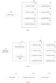
- FIG. 1 is a schematic diagram illustrating a distributed multi-node control system 100 according to a preferred embodiment of the disclosure.
- the distributed multi-node control system 100 includes a control node 10, a plurality of servo nodes 20, and a plurality of execution devices 30.
- the control node 10 is communicatively coupled to the servo node 20.
- the servo node 20 is electronically coupled to the execution device 30.
- the above distributed multi-node control system 100 also includes a scheduling control node 40.
- the control node 10 may include, but be not limited to, a first control node 11 and a second control node 12.
- the scheduling control node 40 is communicatively coupled to the first control node 11 and the second control node 12.
- the first control node 11 and the second control node 12 are communicatively coupled to the plurality of servo nodes 20 respectively.
- the first control node 11 is configured to control an operating state of at least one first servo node 21 in the plurality of servo nodes 20.
- the second control node 12 is configured to control an operating state of at least one second servo node 22 in the plurality of servo nodes 20.
- the scheduling control node 40 may be configured to assign servo nodes 20 controlled by each control node 10.
- the scheduling control node 40 is also configured to obtain operating state information of the first control node 11 and the second control node 12 based on a preset time interval, and to adjust the number of the at least one first servo node 21 corresponding to the first control node 11 and the number of the at least one second servo node 22 corresponding to the second control node 12 based on the operating state information.
- the above operating state information may include system occupancy information, load information, and the like.
- the plurality of servo nodes 20 are assigned to the plurality of control nodes 10, thereby reducing a workload of each control node 10 and improving a computation speed.
- both the first control node 11 and the second control node 12 are asymmetry dual-kernel architectures.
- the first control node 11 includes a first kernel 111 for operating a Linux system and a second kernel 112 for operating a RTOS (real time operating system) system.
- the first kernel 111 is configured to receive a control instruction and to send the received control instruction to the second kernel 112.
- the second kernel 112 is configured to calculate an execution instruction corresponding to each first servo node 21 based on the control instruction and the at least one first servo node 21, and to distribute each execution instruction to the corresponding first servo node 21.
- the first kernel 111 for operating the Linux system is configured to communicate and interact with outside world, and to receive instructions, parameters, and the like.
- the second kernel 112 for operating the RTOS system is configured to process data received from the first kernel 111 to generate the execution instruction corresponding to each first servo node 21.
- the above execution instruction may refer to a servo instruction.
- the second kernel 112 is also configured to send the generated execution instruction to the corresponding first servo node 21 via a network.
- the first control node 11 includes a sharing storage area 113.
- the first kernel 111 is configured to convert data that is to be sent to the second kernel 112 into transmission data based on a preset protocol, and to store the transmission data in the sharing storage area 113.
- the first kernel 111 is configured to remind the second kernel 112 to read the transmission data from a corresponding position in the sharing storage area 113.
- data sent by the Linux system may be converted into data recognizable by the RTOS system based on the preset protocol.
- data sent by the RTOS system may be converted into data recognizable by the Linux system based on the preset protocol.
- the first control node 11 is configured to obtain operating state data of the first servo node 21 and the corresponding execution device 30 based on a preset time interval.
- the first control node 11 is configured to start an abnormal warning operation when the operating state data obtained by the first control node 21 belongs to abnormal state data.
- a way for determining whether the operating state data belongs to the abnormal state data may include: comparing the operating state data returned by the servo node 20 or the operating state data returned by the corresponding execution device 30 with expected operating state data, thereby determining whether the operating state data belongs to the abnormal state data; or determining whether the operating state data returned by the servo node 20 or the operating state data returned by the corresponding execution device 30 includes abnormal information.
- the above abnormal warning operation may be performed by displaying an identifier of an execution device corresponding to the abnormal state data on a display unit of the first control node 11. For example, when the operating state data returned by the servo node 20 to the first control node 11 belongs to the abnormal state data, identification information of the servo node 20 is displayed on the display unit, which is convenient for a maintenance personnel to repair the execution device.
- the second control node 12 includes a third kernel for operating the Linux system and a fourth kernel for operating the RTOS system.
- the third kernel is configured to receive a control instruction and to send the received control instruction to the fourth kernel.
- the fourth kernel is configured to calculate an execution instruction corresponding to each second servo node 22 based on the control instruction and the at least one second servo node 22, and to distribute each execution instruction to the corresponding second servo node 22.
- the third kernel for operating the Linux system is configured to communicate and interact with outside world, and to receive instructions, parameters, and the like.
- the fourth kernel for operating the RTOS system is configured to process data received from the third kernel to generate the execution instruction corresponding to each second servo node 22.
- the above execution instruction may refer to a servo instruction.
- the fourth kernel is also configured to send the generated execution instruction to the corresponding second servo node 22 via the network.
- the second control node 12 also includes a sharing storage area 113.
- the third kernel is configured to convert data that is to be sent to the fourth kernel into transmission data based on a preset protocol, and to store the transmission data in the sharing storage area 113. It should be noted that, data sent by the Linux system may be converted into data recognizable by the RTOS system based on the preset protocol.
- the third kernel is configured to send a triggering instruction to the fourth kernel after sending the transmission data to the sharing storage area 113, to remind the fourth kernel to read the transmission data from a corresponding position in the sharing storage area 113.
- the second control node 12 is configured to obtain operating state data of the second servo node 22 and the corresponding execution device based on the preset time interval.
- the second control node 12 is configured to start an abnormal warning operation when the operating state data obtained by the second control node 12 belongs to the abnormal state data.
- the servo nodes 20 is a dual-kernel architecture. Dual kernels corresponding to the servo node 20 are configured to operate the RTOS system. The servo node 20 is configured to perform task assignment based on a preset task allocation algorithm according to system resource occupation of the dual kernels after receiving the execution instruction.
- the above execution device may be a control motor or an input/output (I/O) device.
- FIG. 4 is a flow chart illustrating a distributed multi-node control method according to a preferred embodiment of the disclosure.
- the distributed multi-node control method is applied to the above distributed multi-node control system 100.
- the distributed multi-node control method includes the following.
- a first kernel 111 of a first control node 11 receives a control instruction generated when a user operates.
- the first kernel 111 sends the received control instruction to the second kernel 112.
- the first kernel 111 may firstly convert the control instruction into transmission data recognizable by the second kernel 112 based on a preset protocol, and then stores the transmission data in a sharing storage area 113. Then the first kernel 111 triggers the second kernel 112 to obtain a control instruction of the recognizable transmission data converted from the sharing storage area 113.
- the second kernel 112 calculates an execution instruction corresponding to each first servo node 21 based on the control instruction and at least one first servo node 21 corresponding to the first control node.
- the second kernel 112 sends each execution instruction to the corresponding first servo node 21.
- the first servo node 21 controls an operating state of the corresponding execution device 30 based on the received execution instruction.
- the above distributed multi-node control method may also include the following.
- a scheduling control node 40 obtains operating state information of the first control node 11 and the second control node 12 based on a preset time interval
- the above operating state information may refer to system resource occupation information, load information and the like of the control node 10.
- the scheduling control node 40 adjusts the number of the at least one first servo node corresponding to the first control node 11 and the number of the at least one second servo node corresponding to the second control node 12 based on the operating state information.
- the above distributed multi-node control method may also include the follows.
- the first control node 11 obtains operating state data of the first servo node 21 based on a preset time interval, and starts an abnormal warning operation related to the first servo node 21 when the obtained operating state data belongs to abnormal state data.
- the first control node 11 obtains operating state data of the execution device 30 through the first servo node 21 based on the preset time interval.
- the first control node 11 starts an abnormal warning operation related to the execution device 30.
- the second control node 12 obtains the operating state data of the second servo node 22 based on a preset time interval.
- the second control node 12 When the obtained operating state data belongs to the abnormal state data, the second control node 12 starts an abnormal warning operation related to the second servo node 22.
- the second control node 12 obtains the operating state data of the execution device 30 through the second servo node 22 based on the preset time interval.
- the second control node 12 starts an abnormal warning operation related to the execution device 30.
- the failed node may be replaced directly with a new node in the same type without replacing a whole machine. After reconfiguration, the whole machine may continue to run, which is convenient and saves costs. Then troubleshooting is performed on the replaced node, which has advantages that production is not affected and maintenance costs is not reduced
- the distributed multi-node control system includes the first control node, the second control node, the plurality of servo nodes, and the plurality of execution devices.
- the first control node is communicatively coupled to the plurality of servo nodes
- the second control node is communicatively coupled to the plurality of servo nodes.
- Each servo node is electrically coupled to one corresponding execution device and configured to control the operating state of the corresponding execution device.
- the first control node is configured to control the operating state of the at least one first servo node in the plurality of servo nodes
- the second control node is configured to control the operating state of the at least one second servo node in the plurality of servo nodes.
- each block in the flow chart or block diagram may represent a module, program segment or part of codes, which contain one or more executable instructions configured to implement specified logical functions.
- the functions noted in the blocks may also occur in an order different from those noted in the accompanying drawings. For example, two consecutive blocks may actually be executed in parallel, and sometimes executed in a reverse order, depending on the involved functions.
- each block and combinations of blocks in the block diagrams and/or flow charts may be implemented with dedicated hardware-based systems for performing specified functions or actions, or may be implemented with a combination of dedicated hardware and computer instructions.
- each functional module in each embodiment of the disclosure may be integrated together to form an independent part or exist alone, or two or more functional modules may also be integrated to form an independent part.
- the computer software product is stored in a storage medium and includes several instructions to enable a computer device (such as a personal computer, a server, or a network device) to execute all or part of the steps of the method described in each embodiment of the disclosure.
- the above storage media includes medias that may store program codes, such as, a U disk, a mobile hard disk, a read-only memory (ROM), a random access memory (RAM), a magnetic disk or an optical disk.
Landscapes
- Engineering & Computer Science (AREA)
- General Physics & Mathematics (AREA)
- Physics & Mathematics (AREA)
- Automation & Control Theory (AREA)
- Software Systems (AREA)
- Theoretical Computer Science (AREA)
- Human Computer Interaction (AREA)
- Manufacturing & Machinery (AREA)
- General Engineering & Computer Science (AREA)
- Quality & Reliability (AREA)
- Programmable Controllers (AREA)
- Testing And Monitoring For Control Systems (AREA)
- Numerical Control (AREA)
- Control By Computers (AREA)
- General Factory Administration (AREA)
- Safety Devices In Control Systems (AREA)
Description
- The disclosure relates to the field of control technologies, more particularly to a distributed multi-node control system and a distributed multi-node control method.
- Industrial robots will play an increasingly important role in future production because of their stability and high efficiency as the development of science and technology. More and more industries may employ the industrial robots instead of people to complete repetitive tasks. Controllers, as the most important part of the industrial robots, may have some practical problems in current applications. On the one hand, a whole machine needs to be repaired once a fault occurs in the controller due to the high integration of the controller, causing a high cost. On the other hand, the controller has a heavy workload and may not guarantee the control efficiency.
US2017075345A1 : a distributed networking system and protocol is provided to a networking system with a modular design. The distributed networking system may include a networking system, modules, control module, user interface module, input/output module, network module, data transmission network, hybrid modules and composite modules. A method to interface with accessories of a system with a modular design using the distributed networking system and protocol is also provided.EP3088971A1 : high availability and data migration in a distributed process control computing environment. Allocation algorithms distribute data and applications among available compute nodes (130), such as controllers in a process control system (100). In the process control system (100), an input/output device, such as a fieldbus module (120), can be used by any controller. Databases (114, 116) store critical execution information for immediate takeover by a backup compute element. The compute nodes (130) are configured to execute algorithms for mitigating dead time in the distributed computing environment. - The invention is defined in the attached set of claims.
- Embodiments of the disclosure provide a distributed multi-node control system. The distributed multi-node control system includes: a first control node, a second control node, a plurality of servo nodes, and a plurality of execution devices, the first control node and the second control node being communicatively coupled to the plurality of servo nodes, and each servo node being electronically coupled to one corresponding execution device and configured to control an operating state of the corresponding execution device; and the first control node is configured to control an operating state of at least one first servo node in the plurality of servo nodes, and the second control node is configured to control an operating state of at least one second servo node in the plurality of servo nodes.
- Further, the distributed multi-node control system also includes: a scheduling control node, and the scheduling control node is communicatively coupled to the first control node and the second control node; and the scheduling control node is configured to obtain operating state information of the first control node and the second control node based on a preset time interval, and to adjust a number of the at least one first servo node corresponding to the first control node and a number of the at least one second servo node corresponding to the second control node based on the operating state information.
- Further, both the first control node and the second control node are asymmetry dual-kernel architectures.
- Further, the first control node includes a first kernel for operating a Linux system and a second kernel for operating a real time operating system. The first kernel is configured to receive a control instruction and to send the received control instruction to the second kernel, and the second kernel is configured to calculate an execution instruction corresponding to each first servo node based on the control instruction and the at least one first servo node, and to distribute each execution instruction to the corresponding first servo node.
- Further, the first control node includes a sharing storage area. The first kernel is configured to convert data that is to be sent to the second kernel, into transmission data based on a preset protocol, and to store the transmission data in the sharing storage area, and the first kernel is configured to remind the second kernel to read the transmission data from a corresponding position in the sharing storage area.
- Further, the second control node includes a third kernel for operating a Linux system and a fourth kernel for operating a real time operating system, the third kernel is configured to receive a control instruction and to send the received control instruction to the fourth kernel, and the fourth kernel is configured to calculate an execution instruction corresponding to each second servo node based on the control instruction and the at least one second servo node, and to distribute each execution instruction to the corresponding second servo node.
- Further, the second control node includes a sharing storage area, the third kernel is configured to convert data that is to be sent to the fourth kernel, into transmission data based on a preset protocol, and to store the transmission data in the sharing storage area, and the third kernel is configured to remind the fourth kernel to read the transmission data from a corresponding position in the sharing storage area.
- Further, each of the plurality of servo nodes are symmetric dual-kernel architectures, and dual cores corresponding to each servo node are configured to operate a real time operating system.
- Further, the first control node is configured to obtain operating state data of the first servo node and the corresponding execution device based on a preset time interval, and to start an abnormal warning operation when the operating state data obtained by the first control node belongs to abnormal state data. The second control node is configured to obtain operating state data of the second servo node and the corresponding execution device based on a preset time interval, and to start an abnormal warning operation when the operating state data obtained by the second control node belongs to abnormal state data.
- Further, the first control node is configured to obtain operating state data of the first servo node based on a preset time interval, and to start an abnormal warning operation when the operating state data obtained by the first control node belongs to abnormal state data; and the second control node is configured to obtain operating state data of the second servo node based on a preset time interval, and to start an abnormal warning operation when the operating state data obtained by the second control node belongs to abnormal state data.
- Further, the first control node is configured to obtain operating state data of the execution device through the corresponding first servo node based on a preset time interval, and to start an abnormal warning operation when the operating state data obtained by the first control node belongs to abnormal state data; and the second control node is configured to obtain operating state data of the execution device through the corresponding second servo node based on a preset time interval, and to start an abnormal warning operation when the operating state data obtained by the second control node belongs to abnormal state data.
- Further, the execution device includes a control motor and an input/output (I/O) device.
- Embodiments of the disclosure provide a distributed multi-node control method, implemented in the first control node in any above distributed multi-node control system. The first control node includes a first kernel and a second kernel. The method includes: receiving, by the first kernel, a control instruction; sending, by the first kernel, the received control instruction to the second kernel; calculating, by the second kernel, an execution instruction corresponding to each first servo node based on the control instruction and the at least one first servo node; sending, by the second kernel, each execution instruction to the corresponding first servo node; and controlling, by the first servo node, an operating state of the corresponding execution device based on the received execution instruction.
- Further, the distributed multi-node control system also includes: a scheduling control node, communicatively coupled to the first control node and the second control node. The method also includes: obtaining, by the scheduling control node, operating state information of the first control node and the second control node based on a preset time interval; and adjusting, by the scheduling control node, a number of the at least one first servo node corresponding to the first control node and a number of the at least one second servo node corresponding to the second control node based on the operating state information.
- Embodiments of the disclosure provide a control node, including: a first kernel configured to receive a control instruction and to send the received control instruction to a second kernel; and the second kernel configured to calculate an execution instruction corresponding to each servo node corresponding to the control node based on the control instruction and each servo node corresponding to the control node, and to distribute each execution instruction to the corresponding first servo node.
- In order to enable the above objectives, features and advantages of the disclosure more obvious and understandable, following detailed description is made below with reference to preferred embodiments and accompanying drawings.
- In order to clearly illustrate technical solutions in embodiments of the disclosure, a brief description is made below to accompanying drawings used in the embodiments. It should be understood that, the following accompanying drawings merely illustrate some embodiments of the disclosure, and do not be considered as a limitation to the scope. For those skilled in the art, other related accompanying drawings may also be obtained based on these accompanying drawings without creative labor.
-
FIG. 1 is a schematic diagram illustrating a distributed multi-node control system according to a preferred embodiment of the disclosure. -
FIG. 2 a schematic diagram illustrating a distributed multi-node control system according to another preferred embodiment of the disclosure. -
FIG. 3 is a schematic diagram illustrating a first control node according to a preferred embodiment of the disclosure. -
FIG. 4 is a flow chart illustrating a distributed multi-node control method according to a preferred embodiment of the disclosure. -
FIG. 5 is a block diagram illustrating another part of a distributed multi-node control method according to a preferred embodiment of the disclosure. - Reference Numerals: 100, distributed multi-node control system; 10, control node; 11, first control node; 111, first kernel; 112, second kernel; 113, sharing storage area; 12, second control node; 20, servo node; 21, first servo node; 22, second servo node; 30, execution device; 40, scheduling control node.
- Description will be made clearly and completely below to the technical solutions in embodiments of the disclosure with reference to accompanying drawings in embodiments of the disclosure. Obviously, the described embodiments are merely a part of the embodiments of the disclosure, not all of the embodiments. Components in embodiments of the disclosure illustrated and described in the accompanying drawings herein may be arranged and designed with different configurations. Therefore, detailed description for embodiments of the disclosure provided in the following accompanying drawings does not limit the claimed protection scope of the disclosure, but merely represents selected embodiments of the disclosure. Based on embodiments of the disclosure, all other embodiments obtained by those skilled in the art without creative labor belong to the protection scope of the disclosure.
- It should be noted that similar items are represented by same numerals and letters in the accompanying drawings. Therefore, once an item is defined in an accompanying drawing, the item does not need to be further defined and explained in the following accompanying drawings. Meanwhile, in the description of the disclosure, terms such as "first" and "second" are used for purposes of distinguishing description and are not understood to indicate or imply relative importance.
- Referring to
FIG. 1, FIG. 1 is a schematic diagram illustrating a distributed multi-node control system 100 according to a preferred embodiment of the disclosure. As illustrated inFIG. 1 , the distributed multi-node control system 100 includes acontrol node 10, a plurality ofservo nodes 20, and a plurality ofexecution devices 30. Thecontrol node 10 is communicatively coupled to theservo node 20. Theservo node 20 is electronically coupled to theexecution device 30. - According to the invention, as illustrated in
FIG. 2 , the above distributed multi-node control system 100 also includes ascheduling control node 40. Thecontrol node 10 may include, but be not limited to, afirst control node 11 and asecond control node 12. Thescheduling control node 40 is communicatively coupled to thefirst control node 11 and thesecond control node 12. Thefirst control node 11 and thesecond control node 12 are communicatively coupled to the plurality ofservo nodes 20 respectively. Thefirst control node 11 is configured to control an operating state of at least onefirst servo node 21 in the plurality ofservo nodes 20. Thesecond control node 12 is configured to control an operating state of at least onesecond servo node 22 in the plurality ofservo nodes 20. Thescheduling control node 40 may be configured to assignservo nodes 20 controlled by eachcontrol node 10. - Further, in order to make full use of resources of each
control node 10, according to the invention, thescheduling control node 40 is also configured to obtain operating state information of thefirst control node 11 and thesecond control node 12 based on a preset time interval, and to adjust the number of the at least onefirst servo node 21 corresponding to thefirst control node 11 and the number of the at least onesecond servo node 22 corresponding to thesecond control node 12 based on the operating state information. The above operating state information may include system occupancy information, load information, and the like. - Comparing with a strategy that all servo devices are centrally controlled by one controller in the related art, with embodiments of the disclosure, the plurality of
servo nodes 20 are assigned to the plurality ofcontrol nodes 10, thereby reducing a workload of eachcontrol node 10 and improving a computation speed. - In embodiments of the disclosure, both the
first control node 11 and thesecond control node 12 are asymmetry dual-kernel architectures. - Alternatively, the
first control node 11 includes afirst kernel 111 for operating a Linux system and asecond kernel 112 for operating a RTOS (real time operating system) system. Thefirst kernel 111 is configured to receive a control instruction and to send the received control instruction to thesecond kernel 112. Thesecond kernel 112 is configured to calculate an execution instruction corresponding to eachfirst servo node 21 based on the control instruction and the at least onefirst servo node 21, and to distribute each execution instruction to the correspondingfirst servo node 21. Thefirst kernel 111 for operating the Linux system is configured to communicate and interact with outside world, and to receive instructions, parameters, and the like. Thesecond kernel 112 for operating the RTOS system is configured to process data received from thefirst kernel 111 to generate the execution instruction corresponding to eachfirst servo node 21. The above execution instruction may refer to a servo instruction. Thesecond kernel 112 is also configured to send the generated execution instruction to the correspondingfirst servo node 21 via a network. - Further, in the above procedure, there is a need to transmit data between the Linux system and the RTOS system, but data interaction between different systems is still incompatible. To solve the problem, according to the invention, as illustrated in
FIG. 3 , thefirst control node 11 includes a sharingstorage area 113. Thefirst kernel 111 is configured to convert data that is to be sent to thesecond kernel 112 into transmission data based on a preset protocol, and to store the transmission data in the sharingstorage area 113. Thefirst kernel 111 is configured to remind thesecond kernel 112 to read the transmission data from a corresponding position in the sharingstorage area 113. In other words, data sent by the Linux system may be converted into data recognizable by the RTOS system based on the preset protocol. Of course, data sent by the RTOS system may be converted into data recognizable by the Linux system based on the preset protocol. - In embodiments of the disclosure, the
first control node 11 is configured to obtain operating state data of thefirst servo node 21 and thecorresponding execution device 30 based on a preset time interval. Thefirst control node 11 is configured to start an abnormal warning operation when the operating state data obtained by thefirst control node 21 belongs to abnormal state data. Alternatively, a way for determining whether the operating state data belongs to the abnormal state data may include: comparing the operating state data returned by theservo node 20 or the operating state data returned by thecorresponding execution device 30 with expected operating state data, thereby determining whether the operating state data belongs to the abnormal state data; or determining whether the operating state data returned by theservo node 20 or the operating state data returned by thecorresponding execution device 30 includes abnormal information. Alternatively, the above abnormal warning operation may be performed by displaying an identifier of an execution device corresponding to the abnormal state data on a display unit of thefirst control node 11. For example, when the operating state data returned by theservo node 20 to thefirst control node 11 belongs to the abnormal state data, identification information of theservo node 20 is displayed on the display unit, which is convenient for a maintenance personnel to repair the execution device. - Alternatively, the
second control node 12 includes a third kernel for operating the Linux system and a fourth kernel for operating the RTOS system. The third kernel is configured to receive a control instruction and to send the received control instruction to the fourth kernel. The fourth kernel is configured to calculate an execution instruction corresponding to eachsecond servo node 22 based on the control instruction and the at least onesecond servo node 22, and to distribute each execution instruction to the correspondingsecond servo node 22. The third kernel for operating the Linux system is configured to communicate and interact with outside world, and to receive instructions, parameters, and the like. The fourth kernel for operating the RTOS system is configured to process data received from the third kernel to generate the execution instruction corresponding to eachsecond servo node 22. The above execution instruction may refer to a servo instruction. The fourth kernel is also configured to send the generated execution instruction to the correspondingsecond servo node 22 via the network. - Further, the
second control node 12 also includes a sharingstorage area 113. The third kernel is configured to convert data that is to be sent to the fourth kernel into transmission data based on a preset protocol, and to store the transmission data in the sharingstorage area 113. It should be noted that, data sent by the Linux system may be converted into data recognizable by the RTOS system based on the preset protocol. The third kernel is configured to send a triggering instruction to the fourth kernel after sending the transmission data to the sharingstorage area 113, to remind the fourth kernel to read the transmission data from a corresponding position in the sharingstorage area 113. - In embodiments of the disclosure, the
second control node 12 is configured to obtain operating state data of thesecond servo node 22 and the corresponding execution device based on the preset time interval. Thesecond control node 12 is configured to start an abnormal warning operation when the operating state data obtained by thesecond control node 12 belongs to the abnormal state data. - In embodiments of the disclosure, the
servo nodes 20 is a dual-kernel architecture. Dual kernels corresponding to theservo node 20 are configured to operate the RTOS system. Theservo node 20 is configured to perform task assignment based on a preset task allocation algorithm according to system resource occupation of the dual kernels after receiving the execution instruction. - In embodiments of the disclosure, the above execution device may be a control motor or an input/output (I/O) device.
- Referring to
FIG. 4, FIG. 4 is a flow chart illustrating a distributed multi-node control method according to a preferred embodiment of the disclosure. The distributed multi-node control method is applied to the above distributed multi-node control system 100. - As illustrated in
FIG. 4 , the distributed multi-node control method includes the following. - At block S101, a
first kernel 111 of afirst control node 11 receives a control instruction generated when a user operates. - At block S102, the
first kernel 111 sends the received control instruction to thesecond kernel 112. - In some embodiments, the
first kernel 111 may firstly convert the control instruction into transmission data recognizable by thesecond kernel 112 based on a preset protocol, and then stores the transmission data in a sharingstorage area 113. Then thefirst kernel 111 triggers thesecond kernel 112 to obtain a control instruction of the recognizable transmission data converted from the sharingstorage area 113. - At block S103, the
second kernel 112 calculates an execution instruction corresponding to eachfirst servo node 21 based on the control instruction and at least onefirst servo node 21 corresponding to the first control node. - At block S104, the
second kernel 112 sends each execution instruction to the correspondingfirst servo node 21. - At block S105, the
first servo node 21 controls an operating state of thecorresponding execution device 30 based on the received execution instruction. - It should be noted that, a processing flow for all the
control nodes 10 receiving the control instructions, parameters or the like generated by a user operation is basically the same as the above actions, which is not be elaborated here. - Further, as illustrated in
FIG. 5 , the above distributed multi-node control method may also include the following. - At block S201, a
scheduling control node 40 obtains operating state information of thefirst control node 11 and thesecond control node 12 based on a preset time interval
In embodiments of the disclosure, the above operating state information may refer to system resource occupation information, load information and the like of thecontrol node 10. - At block S202, the
scheduling control node 40 adjusts the number of the at least one first servo node corresponding to thefirst control node 11 and the number of the at least one second servo node corresponding to thesecond control node 12 based on the operating state information. - Further, the above distributed multi-node control method may also include the follows. The
first control node 11 obtains operating state data of thefirst servo node 21 based on a preset time interval, and starts an abnormal warning operation related to thefirst servo node 21 when the obtained operating state data belongs to abnormal state data. Thefirst control node 11 obtains operating state data of theexecution device 30 through thefirst servo node 21 based on the preset time interval. When the obtained operating state data belongs to the abnormal state data, thefirst control node 11 starts an abnormal warning operation related to theexecution device 30. Thesecond control node 12 obtains the operating state data of thesecond servo node 22 based on a preset time interval. When the obtained operating state data belongs to the abnormal state data, thesecond control node 12 starts an abnormal warning operation related to thesecond servo node 22. Thesecond control node 12 obtains the operating state data of theexecution device 30 through thesecond servo node 22 based on the preset time interval. When the obtained operating state data belongs to the abnormal state data, thesecond control node 12 starts an abnormal warning operation related to theexecution device 30. In this way, when a certain node fails in an operating period, the failed node may be replaced directly with a new node in the same type without replacing a whole machine. After reconfiguration, the whole machine may continue to run, which is convenient and saves costs. Then troubleshooting is performed on the replaced node, which has advantages that production is not affected and maintenance costs is not reduced - In conclusion, with the distributed multi-node control system and method provided in the disclosure, the distributed multi-node control system includes the first control node, the second control node, the plurality of servo nodes, and the plurality of execution devices. The first control node is communicatively coupled to the plurality of servo nodes, and the second control node is communicatively coupled to the plurality of servo nodes. Each servo node is electrically coupled to one corresponding execution device and configured to control the operating state of the corresponding execution device. The first control node is configured to control the operating state of the at least one first servo node in the plurality of servo nodes, and the second control node is configured to control the operating state of the at least one second servo node in the plurality of servo nodes. A real-time computation is shared by a plurality of control nodes, thereby realizing a distributed control and speeding up the computation. Moreover, such system coordinating and cooperating with the plurality of control nodes is convenient for maintenance and saves maintenance cost.
- In the plurality of embodiments provided by the disclosure, it should be understood that, the device and the method disclosed may also be implemented in other ways. The device embodiments described above are merely exemplary. For example, the flow charts and the block diagrams in the accompanying drawings illustrate architectures, functions and operations of possible implementations according to devices, methods and computer program products of a plurality of embodiments of the disclosure. Each block in the flow chart or block diagram may represent a module, program segment or part of codes, which contain one or more executable instructions configured to implement specified logical functions. It should be noted that, in some alternative implementations, the functions noted in the blocks may also occur in an order different from those noted in the accompanying drawings. For example, two consecutive blocks may actually be executed in parallel, and sometimes executed in a reverse order, depending on the involved functions. It also needs to be noted that, each block and combinations of blocks in the block diagrams and/or flow charts may be implemented with dedicated hardware-based systems for performing specified functions or actions, or may be implemented with a combination of dedicated hardware and computer instructions.
- In addition, each functional module in each embodiment of the disclosure may be integrated together to form an independent part or exist alone, or two or more functional modules may also be integrated to form an independent part.
- When the functions are realized in the form of software function modules, and sold or used as independent products, they may be stored in a computer readable storage medium. Based on this understanding, the technical solution of the disclosure, the part that contributes to the related art, or the part of the technical solution may be embodied in the form of software products in essence. The computer software product is stored in a storage medium and includes several instructions to enable a computer device (such as a personal computer, a server, or a network device) to execute all or part of the steps of the method described in each embodiment of the disclosure. The above storage media includes medias that may store program codes, such as, a U disk, a mobile hard disk, a read-only memory (ROM), a random access memory (RAM), a magnetic disk or an optical disk.
- It should be noted that, in the description, relationship terms such as "first" and "second" are merely used to distinguish one entity or operation from another, and do not necessarily require or imply any such actual relationship or order between these entities or operations. The terms "comprising", "including" or any other variation thereof are intended to cover non-exclusive inclusion, such that a process, method, article or device including a series of elements includes not only those elements, but also other elements not explicitly listed, or elements inherent to such process, method, article or device. Without further limitation, it is not excluded that additional same elements exist in the process, method, article or device including elements defined by the sentence "including one ......".
Claims (12)
- A distributed multi-node control system (100), comprising:a first control node (11), a second control node (12), a plurality of servo nodes (20), and a plurality of execution devices (30),the first control node and the second control node being communicatively coupled to the plurality of servo nodes, andeach of the servo nodes being electronically coupled to a corresponding one of the execution devices and configured to control an operating state of the corresponding execution device; andthe first control node is configured to control an operating state of at least one first servo node in the plurality of servo nodes, andthe second control node is configured to control an operating state of at least one second servo node in the plurality of servo nodes,whereinthe distributed multi-node control system further comprises: a scheduling control node (40), andthe scheduling control node is communicatively coupled to the first control node and the second control node;being characterized in that:the scheduling control node is configured to obtain operating state information of the first control node and the second control node based on a preset time interval, and to adjusta number of the at least one first servo node controlled by the first control node anda number of the at least one second servo node controlled by the second control node based on the operating state information;wherein the first control node comprises a first kernel and a second kernel, andwherein the first kernel is configuredto receive a control instruction, andto send the received control instruction to the second kernel;wherein the second kernel is configuredto calculate an execution instruction corresponding to each of the first servo nodes based on the control instruction and the at least one first servo node,to send each execution instruction to each of the first servo nodes;wherein each of the first servo nodes is configured to control an operating state of the corresponding execution device based on the received execution instruction.
- The system of claim 1, wherein both the first control node (11) and the second control node (12) are asymmetric dual-kernel architectures.
- The system of claim 2, wherein the first control node (11) comprises a first kernel (111) for operating a Linux system and a second kernel (112) for operating a real time operating system, the first kernel (111) is configured to receive a control instruction and to send the received control instruction to the second kernel (112), and the second kernel (112) is configured to calculate an execution instruction corresponding to each first servo node (21) based on the control instruction and the at least one first servo node (21), and to distribute each execution instruction to the corresponding first servo node (21).
- The system of claim 3, wherein the first control node (11) comprises a sharing storage area (113), the first kernel (111) is configured to convert data that is to be sent to the second kernel (112), into transmission data based on a preset protocol, and to store the transmission data in the sharing storage area (113), and the first kernel (111) is configured to instruct the second kernel (112) to read the transmission data from a corresponding position in the sharing storage area (113).
- The system of claim 3 or 4, wherein the second control node (12) comprises a third kernel for operating a Linux system and a fourth kernel for operating a real time operating system, the third kernel is configured to receive a control instruction and to send the received control instruction to the fourth kernel, and the fourth kernel is configured to calculate an execution instruction corresponding to each second servo node (22) based on the control instruction and the at least one second servo node (22), and to distribute each execution instruction to the corresponding second servo node (22).
- The system of claim 5, wherein the second control node (12) comprises a sharing storage area, the third kernel is configured to convert data that is to be sent to the fourth kernel, into transmission data based on a preset protocol, and to store the transmission data in the sharing storage area, and the third kernel is configured to instruct the fourth kernel to read the transmission data from a corresponding position in the sharing storage area.
- The system of claim 1, wherein each of the plurality of servo nodes (20) are symmetric dual-kernel architectures, and dual kernels of each servo node (20) are configured to operate a real time operating system.
- The system of claim 1, whereinthe first control node is configuredto obtain operating state data of the at least one first servo node and the corresponding at least one execution device based on the preset time interval, andto start an abnormal warning operation when the operating state data obtained by the first control node belongs to abnormal state data; andthe second control node is configuredto obtain operating state data of the at least one second servo node and the corresponding at least one execution device based on the preset time interval, andto start an abnormal warning operation when the operating state data obtained by the second control node belongs to the abnormal state data.
- The system of claim 1, wherein,the first control node is configuredto obtain operating state data of the at least one first servo node based on the preset time interval, andto start an abnormal warning operation when the operating state data obtained by the first control node belongs to abnormal state data; andthe second control node is configured to obtain operating state data of the at least one second servo node based on the preset time interval, andto start an abnormal warning operation when the operating state data obtained by the second control node belongs to the abnormal state data.
- The system of claim 1, wherein,the first control node is configured to obtain operating state data of the corresponding at least one execution device through the corresponding at least one first servo node based on the preset time interval, andto start an abnormal warning operation when the operating state data obtained by the first control node belongs to abnormal state data; andthe second control node is configured to obtain operating state data of the corresponding at least one execution device through the corresponding at least one second servo node based on the preset time interval, andto start an abnormal warning operation when the operating state data obtained by the second control node belongs to the abnormal state data.
- The system of claim 1, wherein each of the plurality of execution devices (30) comprises a control motor and an input/output (I/O) device
- A distributed multi-node control method of operating the distributed multi-node control system according to any one of claims 1 to 11,wherein the first control node comprises a first kernel and a second kernel, andthe method comprises:receiving (S101), by the first kernel, a control instruction;sending (S102), by the first kernel, the received control instruction to the second kernel;calculating (S103), by the second kernel, an execution instruction corresponding to each of the first servo nodes based on the control instruction and the at least one first servo node;sending (S104), by the second kernel, each execution instruction to each of the first servo nodes; and controlling (S105), by each of the first servo nodes, an operating state of the corresponding execution device based on the received execution instruction,the method further comprises:obtaining (S201), by the scheduling control node, operating state information of the first control node and the second control node based on the preset time interval;being characterized by the steps:
adjusting (S202), by the scheduling control node, a number of the at least one first servo node controlled by the first control node and a number of the at least one second servo node controlled by the second control node based on the operating state information.
Applications Claiming Priority (2)
| Application Number | Priority Date | Filing Date | Title |
|---|---|---|---|
| CN201810637356.4A CN108614460B (en) | 2018-06-20 | 2018-06-20 | Distributed multi-node control system and method |
| PCT/CN2019/092124 WO2019242696A1 (en) | 2018-06-20 | 2019-06-20 | Distributed multi-node control system and method |
Publications (3)
| Publication Number | Publication Date |
|---|---|
| EP3812856A1 EP3812856A1 (en) | 2021-04-28 |
| EP3812856A4 EP3812856A4 (en) | 2022-06-08 |
| EP3812856B1 true EP3812856B1 (en) | 2024-08-28 |
Family
ID=63665428
Family Applications (1)
| Application Number | Title | Priority Date | Filing Date |
|---|---|---|---|
| EP19821703.6A Active EP3812856B1 (en) | 2018-06-20 | 2019-06-20 | Distributed multi-node control system and method |
Country Status (6)
| Country | Link |
|---|---|
| US (1) | US11681271B2 (en) |
| EP (1) | EP3812856B1 (en) |
| JP (1) | JP7507098B2 (en) |
| KR (1) | KR102834216B1 (en) |
| CN (1) | CN108614460B (en) |
| WO (1) | WO2019242696A1 (en) |
Families Citing this family (3)
| Publication number | Priority date | Publication date | Assignee | Title |
|---|---|---|---|---|
| CN108614460B (en) * | 2018-06-20 | 2020-11-06 | 东莞市李群自动化技术有限公司 | Distributed multi-node control system and method |
| US20250123600A1 (en) * | 2022-03-18 | 2025-04-17 | Telefonaktiebolaget Lm Ericsson (Publ) | Methods, Computing Nodes and System for Controlling a Physical Entity |
| CN121348930A (en) * | 2025-12-19 | 2026-01-16 | 四川航天烽火伺服控制技术有限公司 | Intelligent attitude control system with multi-servo node collaborative response |
Citations (1)
| Publication number | Priority date | Publication date | Assignee | Title |
|---|---|---|---|---|
| US20180121240A1 (en) * | 2015-06-26 | 2018-05-03 | Alibaba Group Holding Limited | Job Scheduling Method, Device, and Distributed System |
Family Cites Families (36)
| Publication number | Priority date | Publication date | Assignee | Title |
|---|---|---|---|---|
| JPH08179816A (en) * | 1994-12-26 | 1996-07-12 | Shimadzu Corp | Distributed control system |
| US7136725B1 (en) * | 2001-06-21 | 2006-11-14 | Paciorek Ronald R | Load shed notification method, product, and apparatus |
| CN1273890C (en) * | 2004-04-30 | 2006-09-06 | 浙江大学 | Micro-kernel design method for ARM processor framework |
| JP2006059308A (en) | 2004-08-17 | 2006-03-02 | Hiroki Maruchi | General-purposed and real-timed information processor |
| US9201703B2 (en) | 2006-06-07 | 2015-12-01 | International Business Machines Corporation | Sharing kernel services among kernels |
| CN101174960A (en) * | 2006-10-30 | 2008-05-07 | 丹东华通测控有限公司 | Redundant intelligent network communication controller |
| CN101226397A (en) * | 2008-02-04 | 2008-07-23 | 南京理工大学 | High-reliability distributed Ethernet measurement and control system |
| CN101620437A (en) * | 2008-07-02 | 2010-01-06 | 中国铝业股份有限公司 | Method for connecting production networks and production network connecting system |
| CN101662551B (en) * | 2008-08-29 | 2012-02-22 | 深圳市东进通讯技术股份有限公司 | Enterprise converged communication system |
| CN102117061B (en) * | 2009-12-31 | 2014-09-17 | 北京国电智深控制技术有限公司 | Distributive control system |
| US9471532B2 (en) * | 2011-02-11 | 2016-10-18 | Microsoft Technology Licensing, Llc | Remote core operations in a multi-core computer |
| DE102011107169A1 (en) * | 2011-07-13 | 2013-01-17 | Kuka Roboter Gmbh | Control of a robot |
| US9448849B2 (en) * | 2011-08-31 | 2016-09-20 | Oracle International Corporation | Preventing oscillatory load behavior in a multi-node distributed system |
| GB2501676A (en) * | 2012-03-30 | 2013-11-06 | Torquing Technology Ltd | Autonomous cell control system |
| US8768492B2 (en) | 2012-05-21 | 2014-07-01 | Tait Towers Manufacturing Llc | Automation and motion control system |
| JP6317974B2 (en) * | 2014-03-28 | 2018-04-25 | アズビル株式会社 | Data collection system |
| JP2015197802A (en) * | 2014-04-01 | 2015-11-09 | キヤノン株式会社 | Information processing device, information processing method and program |
| JP6563187B2 (en) * | 2014-11-12 | 2019-08-21 | 株式会社東芝 | Distributed control system, control device, and control method |
| KR101790152B1 (en) * | 2015-03-06 | 2017-10-25 | 두산중공업 주식회사 | System and method for restoring plant data in distributed controller system |
| US10437212B2 (en) * | 2015-04-28 | 2019-10-08 | Schneider Electric Systems Usa, Inc. | Distributed computing in a process control environment |
| CN104898481A (en) * | 2015-05-05 | 2015-09-09 | 湘潭大学 | Dynamic reconstruction method for parallel inverters |
| KR101834614B1 (en) * | 2015-06-15 | 2018-03-06 | 엘에스산전 주식회사 | Motion control system |
| US10514683B2 (en) | 2015-09-16 | 2019-12-24 | Profire Energy, Inc. | Distributed networking system and method to implement a safety state environment |
| CN105183570A (en) * | 2015-09-22 | 2015-12-23 | 上海斐讯数据通信技术有限公司 | System and method for sending large quantities of QINQ configuration data to core process |
| CN106874142B (en) * | 2015-12-11 | 2020-08-07 | 华为技术有限公司 | Real-time data fault-tolerant processing method and system |
| CN105824303B (en) * | 2016-05-17 | 2018-11-23 | 上海颖电控制技术有限公司 | A kind of distributed intelligence blind controller system and its method based on Internet of Things |
| CN105871740B (en) * | 2016-06-27 | 2019-04-23 | 联想(北京)有限公司 | A kind of communication means of distributed network, system and control node |
| CN106301522B (en) * | 2016-08-20 | 2020-05-26 | 航天恒星科技有限公司 | Visual fault diagnosis method and system for data receiving task of remote sensing satellite ground station |
| CN106444685A (en) * | 2016-12-06 | 2017-02-22 | 中国船舶重工集团公司第七〇九研究所 | Distributed control system and method of distributed control system for dynamic scheduling resources |
| JP3211204U (en) * | 2017-04-12 | 2017-06-29 | コリア インスティチュート オブ オーシャン サイエンス アンド テクノロジー | Integrated solution system for ship and offshore plant production simulation |
| CN107037795B (en) * | 2017-04-19 | 2020-07-14 | 唐志 | Industrial process control process guidance system |
| US10467056B2 (en) * | 2017-05-12 | 2019-11-05 | Google Llc | Configuration of application software on multi-core image processor |
| CN107577185B (en) * | 2017-09-14 | 2019-10-25 | 浙江国自机器人技术有限公司 | A kind of task executing method and the controller based on multi-core processor |
| JP6897462B2 (en) * | 2017-09-27 | 2021-06-30 | オムロン株式会社 | Control system and communication method |
| CN107765613A (en) * | 2017-12-07 | 2018-03-06 | 成都量之星科技有限公司 | A kind of dcs of intelligent robot |
| CN108614460B (en) * | 2018-06-20 | 2020-11-06 | 东莞市李群自动化技术有限公司 | Distributed multi-node control system and method |
-
2018
- 2018-06-20 CN CN201810637356.4A patent/CN108614460B/en active Active
-
2019
- 2019-06-20 EP EP19821703.6A patent/EP3812856B1/en active Active
- 2019-06-20 KR KR1020207037243A patent/KR102834216B1/en active Active
- 2019-06-20 JP JP2020568673A patent/JP7507098B2/en active Active
- 2019-06-20 US US17/054,410 patent/US11681271B2/en active Active
- 2019-06-20 WO PCT/CN2019/092124 patent/WO2019242696A1/en not_active Ceased
Patent Citations (1)
| Publication number | Priority date | Publication date | Assignee | Title |
|---|---|---|---|---|
| US20180121240A1 (en) * | 2015-06-26 | 2018-05-03 | Alibaba Group Holding Limited | Job Scheduling Method, Device, and Distributed System |
Also Published As
| Publication number | Publication date |
|---|---|
| EP3812856A4 (en) | 2022-06-08 |
| US20210240163A1 (en) | 2021-08-05 |
| EP3812856A1 (en) | 2021-04-28 |
| WO2019242696A1 (en) | 2019-12-26 |
| CN108614460B (en) | 2020-11-06 |
| KR20210022003A (en) | 2021-03-02 |
| CN108614460A (en) | 2018-10-02 |
| KR102834216B1 (en) | 2025-07-15 |
| JP2021530760A (en) | 2021-11-11 |
| US11681271B2 (en) | 2023-06-20 |
| JP7507098B2 (en) | 2024-06-27 |
Similar Documents
| Publication | Publication Date | Title |
|---|---|---|
| Krishnamoorthy et al. | Production inventory with service time and vacation to the server | |
| CN106200571B (en) | Distributed computing device and method in processing control environment | |
| US11681271B2 (en) | Distributed multi-node control system and method, and control node | |
| JP6563187B2 (en) | Distributed control system, control device, and control method | |
| CN105159736B (en) | A kind of construction method for the SaaS software deployment schemes for supporting performance evaluation | |
| Mohagheghi et al. | Dynamic demand response: A solution for improved energy efficiency for industrial customers | |
| WO2015169352A1 (en) | Flexible controller utilization in a process control system | |
| JP2022192052A5 (en) | ||
| CN115622893B (en) | Distributed arrangement system and method for micro-services at edge of space-based network | |
| CN112631207B (en) | Numerical control system based on industrial server cluster | |
| Morariu et al. | Redundancy and scalability for virtualized MES systems with programmable infrastructure | |
| EP3871057B1 (en) | Method, apparatus and system for managing alarms | |
| EP3918542A1 (en) | Dynamic deploying a mom module across a plurality of layers | |
| Zhu et al. | User-centered information provision of cyber-physical machine tools | |
| JP3643478B2 (en) | Control system | |
| CN104486447A (en) | Large platform cluster system based on Big-Cluster | |
| JP6036848B2 (en) | Information processing system | |
| TWI806106B (en) | Autonomous mobile robots and peer-to-peer interaction management system | |
| Topaloğlu | Industrial automation and edge computing scada plc pac io-link-2 | |
| Arumugam et al. | Inventory based allocation policies for flexible servers in serial systems | |
| Koch et al. | Tackling Problems on Maintenance and Evolution in Industry 4.0 Scenarios Using a Distributed Architecture. | |
| CN119961000B (en) | Scheduling optimization method and system applied to AI edge computing server | |
| Mersch et al. | Service-orientation on behalf of self-configuration for the automation environment | |
| KR20250105033A (en) | Systemf for operating a smart factory for efficient logistics work and monitoring and method for operating a smart factory using the same | |
| CN121352931A (en) | Asynchronous duplex multi-robot collaborative system and method |
Legal Events
| Date | Code | Title | Description |
|---|---|---|---|
| STAA | Information on the status of an ep patent application or granted ep patent |
Free format text: STATUS: THE INTERNATIONAL PUBLICATION HAS BEEN MADE |
|
| PUAI | Public reference made under article 153(3) epc to a published international application that has entered the european phase |
Free format text: ORIGINAL CODE: 0009012 |
|
| STAA | Information on the status of an ep patent application or granted ep patent |
Free format text: STATUS: REQUEST FOR EXAMINATION WAS MADE |
|
| 17P | Request for examination filed |
Effective date: 20201203 |
|
| AK | Designated contracting states |
Kind code of ref document: A1 Designated state(s): AL AT BE BG CH CY CZ DE DK EE ES FI FR GB GR HR HU IE IS IT LI LT LU LV MC MK MT NL NO PL PT RO RS SE SI SK SM TR |
|
| AX | Request for extension of the european patent |
Extension state: BA ME |
|
| DAV | Request for validation of the european patent (deleted) | ||
| DAX | Request for extension of the european patent (deleted) | ||
| RIC1 | Information provided on ipc code assigned before grant |
Ipc: G06F 9/54 20060101ALI20220125BHEP Ipc: G05B 19/418 20060101ALI20220125BHEP Ipc: G05B 19/042 20060101ALI20220125BHEP Ipc: G05B 19/04 20060101AFI20220125BHEP |
|
| A4 | Supplementary search report drawn up and despatched |
Effective date: 20220506 |
|
| RIC1 | Information provided on ipc code assigned before grant |
Ipc: G06F 9/54 20060101ALI20220429BHEP Ipc: G05B 19/418 20060101ALI20220429BHEP Ipc: G05B 19/042 20060101ALI20220429BHEP Ipc: G05B 19/04 20060101AFI20220429BHEP |
|
| GRAP | Despatch of communication of intention to grant a patent |
Free format text: ORIGINAL CODE: EPIDOSNIGR1 |
|
| STAA | Information on the status of an ep patent application or granted ep patent |
Free format text: STATUS: GRANT OF PATENT IS INTENDED |
|
| INTG | Intention to grant announced |
Effective date: 20240409 |
|
| GRAS | Grant fee paid |
Free format text: ORIGINAL CODE: EPIDOSNIGR3 |
|
| GRAA | (expected) grant |
Free format text: ORIGINAL CODE: 0009210 |
|
| STAA | Information on the status of an ep patent application or granted ep patent |
Free format text: STATUS: THE PATENT HAS BEEN GRANTED |
|
| AK | Designated contracting states |
Kind code of ref document: B1 Designated state(s): AL AT BE BG CH CY CZ DE DK EE ES FI FR GB GR HR HU IE IS IT LI LT LU LV MC MK MT NL NO PL PT RO RS SE SI SK SM TR |
|
| REG | Reference to a national code |
Ref country code: CH Ref legal event code: EP |
|
| REG | Reference to a national code |
Ref country code: DE Ref legal event code: R096 Ref document number: 602019057996 Country of ref document: DE |
|
| REG | Reference to a national code |
Ref country code: IE Ref legal event code: FG4D |
|
| REG | Reference to a national code |
Ref country code: LT Ref legal event code: MG9D |
|
| PG25 | Lapsed in a contracting state [announced via postgrant information from national office to epo] |
Ref country code: NO Free format text: LAPSE BECAUSE OF FAILURE TO SUBMIT A TRANSLATION OF THE DESCRIPTION OR TO PAY THE FEE WITHIN THE PRESCRIBED TIME-LIMIT Effective date: 20241128 |
|
| REG | Reference to a national code |
Ref country code: AT Ref legal event code: MK05 Ref document number: 1718630 Country of ref document: AT Kind code of ref document: T Effective date: 20240828 |
|
| PG25 | Lapsed in a contracting state [announced via postgrant information from national office to epo] |
Ref country code: NL Free format text: LAPSE BECAUSE OF FAILURE TO SUBMIT A TRANSLATION OF THE DESCRIPTION OR TO PAY THE FEE WITHIN THE PRESCRIBED TIME-LIMIT Effective date: 20240828 Ref country code: PT Free format text: LAPSE BECAUSE OF FAILURE TO SUBMIT A TRANSLATION OF THE DESCRIPTION OR TO PAY THE FEE WITHIN THE PRESCRIBED TIME-LIMIT Effective date: 20241230 Ref country code: FI Free format text: LAPSE BECAUSE OF FAILURE TO SUBMIT A TRANSLATION OF THE DESCRIPTION OR TO PAY THE FEE WITHIN THE PRESCRIBED TIME-LIMIT Effective date: 20240828 Ref country code: GR Free format text: LAPSE BECAUSE OF FAILURE TO SUBMIT A TRANSLATION OF THE DESCRIPTION OR TO PAY THE FEE WITHIN THE PRESCRIBED TIME-LIMIT Effective date: 20241129 Ref country code: PL Free format text: LAPSE BECAUSE OF FAILURE TO SUBMIT A TRANSLATION OF THE DESCRIPTION OR TO PAY THE FEE WITHIN THE PRESCRIBED TIME-LIMIT Effective date: 20240828 |
|
| PG25 | Lapsed in a contracting state [announced via postgrant information from national office to epo] |
Ref country code: BG Free format text: LAPSE BECAUSE OF FAILURE TO SUBMIT A TRANSLATION OF THE DESCRIPTION OR TO PAY THE FEE WITHIN THE PRESCRIBED TIME-LIMIT Effective date: 20240828 |
|
| PG25 | Lapsed in a contracting state [announced via postgrant information from national office to epo] |
Ref country code: LV Free format text: LAPSE BECAUSE OF FAILURE TO SUBMIT A TRANSLATION OF THE DESCRIPTION OR TO PAY THE FEE WITHIN THE PRESCRIBED TIME-LIMIT Effective date: 20240828 |
|
| REG | Reference to a national code |
Ref country code: NL Ref legal event code: MP Effective date: 20240828 |
|
| PG25 | Lapsed in a contracting state [announced via postgrant information from national office to epo] |
Ref country code: AT Free format text: LAPSE BECAUSE OF FAILURE TO SUBMIT A TRANSLATION OF THE DESCRIPTION OR TO PAY THE FEE WITHIN THE PRESCRIBED TIME-LIMIT Effective date: 20240828 Ref country code: IS Free format text: LAPSE BECAUSE OF FAILURE TO SUBMIT A TRANSLATION OF THE DESCRIPTION OR TO PAY THE FEE WITHIN THE PRESCRIBED TIME-LIMIT Effective date: 20241228 |
|
| PG25 | Lapsed in a contracting state [announced via postgrant information from national office to epo] |
Ref country code: HR Free format text: LAPSE BECAUSE OF FAILURE TO SUBMIT A TRANSLATION OF THE DESCRIPTION OR TO PAY THE FEE WITHIN THE PRESCRIBED TIME-LIMIT Effective date: 20240828 |
|
| PG25 | Lapsed in a contracting state [announced via postgrant information from national office to epo] |
Ref country code: RS Free format text: LAPSE BECAUSE OF FAILURE TO SUBMIT A TRANSLATION OF THE DESCRIPTION OR TO PAY THE FEE WITHIN THE PRESCRIBED TIME-LIMIT Effective date: 20241128 Ref country code: ES Free format text: LAPSE BECAUSE OF FAILURE TO SUBMIT A TRANSLATION OF THE DESCRIPTION OR TO PAY THE FEE WITHIN THE PRESCRIBED TIME-LIMIT Effective date: 20240828 |
|
| PG25 | Lapsed in a contracting state [announced via postgrant information from national office to epo] |
Ref country code: RS Free format text: LAPSE BECAUSE OF FAILURE TO SUBMIT A TRANSLATION OF THE DESCRIPTION OR TO PAY THE FEE WITHIN THE PRESCRIBED TIME-LIMIT Effective date: 20241128 Ref country code: PT Free format text: LAPSE BECAUSE OF FAILURE TO SUBMIT A TRANSLATION OF THE DESCRIPTION OR TO PAY THE FEE WITHIN THE PRESCRIBED TIME-LIMIT Effective date: 20241230 Ref country code: PL Free format text: LAPSE BECAUSE OF FAILURE TO SUBMIT A TRANSLATION OF THE DESCRIPTION OR TO PAY THE FEE WITHIN THE PRESCRIBED TIME-LIMIT Effective date: 20240828 Ref country code: NO Free format text: LAPSE BECAUSE OF FAILURE TO SUBMIT A TRANSLATION OF THE DESCRIPTION OR TO PAY THE FEE WITHIN THE PRESCRIBED TIME-LIMIT Effective date: 20241128 Ref country code: NL Free format text: LAPSE BECAUSE OF FAILURE TO SUBMIT A TRANSLATION OF THE DESCRIPTION OR TO PAY THE FEE WITHIN THE PRESCRIBED TIME-LIMIT Effective date: 20240828 Ref country code: LV Free format text: LAPSE BECAUSE OF FAILURE TO SUBMIT A TRANSLATION OF THE DESCRIPTION OR TO PAY THE FEE WITHIN THE PRESCRIBED TIME-LIMIT Effective date: 20240828 Ref country code: IS Free format text: LAPSE BECAUSE OF FAILURE TO SUBMIT A TRANSLATION OF THE DESCRIPTION OR TO PAY THE FEE WITHIN THE PRESCRIBED TIME-LIMIT Effective date: 20241228 Ref country code: HR Free format text: LAPSE BECAUSE OF FAILURE TO SUBMIT A TRANSLATION OF THE DESCRIPTION OR TO PAY THE FEE WITHIN THE PRESCRIBED TIME-LIMIT Effective date: 20240828 Ref country code: GR Free format text: LAPSE BECAUSE OF FAILURE TO SUBMIT A TRANSLATION OF THE DESCRIPTION OR TO PAY THE FEE WITHIN THE PRESCRIBED TIME-LIMIT Effective date: 20241129 Ref country code: FI Free format text: LAPSE BECAUSE OF FAILURE TO SUBMIT A TRANSLATION OF THE DESCRIPTION OR TO PAY THE FEE WITHIN THE PRESCRIBED TIME-LIMIT Effective date: 20240828 Ref country code: ES Free format text: LAPSE BECAUSE OF FAILURE TO SUBMIT A TRANSLATION OF THE DESCRIPTION OR TO PAY THE FEE WITHIN THE PRESCRIBED TIME-LIMIT Effective date: 20240828 Ref country code: BG Free format text: LAPSE BECAUSE OF FAILURE TO SUBMIT A TRANSLATION OF THE DESCRIPTION OR TO PAY THE FEE WITHIN THE PRESCRIBED TIME-LIMIT Effective date: 20240828 Ref country code: AT Free format text: LAPSE BECAUSE OF FAILURE TO SUBMIT A TRANSLATION OF THE DESCRIPTION OR TO PAY THE FEE WITHIN THE PRESCRIBED TIME-LIMIT Effective date: 20240828 |
|
| PG25 | Lapsed in a contracting state [announced via postgrant information from national office to epo] |
Ref country code: DK Free format text: LAPSE BECAUSE OF FAILURE TO SUBMIT A TRANSLATION OF THE DESCRIPTION OR TO PAY THE FEE WITHIN THE PRESCRIBED TIME-LIMIT Effective date: 20240828 Ref country code: RO Free format text: LAPSE BECAUSE OF FAILURE TO SUBMIT A TRANSLATION OF THE DESCRIPTION OR TO PAY THE FEE WITHIN THE PRESCRIBED TIME-LIMIT Effective date: 20240828 Ref country code: SM Free format text: LAPSE BECAUSE OF FAILURE TO SUBMIT A TRANSLATION OF THE DESCRIPTION OR TO PAY THE FEE WITHIN THE PRESCRIBED TIME-LIMIT Effective date: 20240828 |
|
| PG25 | Lapsed in a contracting state [announced via postgrant information from national office to epo] |
Ref country code: EE Free format text: LAPSE BECAUSE OF FAILURE TO SUBMIT A TRANSLATION OF THE DESCRIPTION OR TO PAY THE FEE WITHIN THE PRESCRIBED TIME-LIMIT Effective date: 20240828 |
|
| PG25 | Lapsed in a contracting state [announced via postgrant information from national office to epo] |
Ref country code: CZ Free format text: LAPSE BECAUSE OF FAILURE TO SUBMIT A TRANSLATION OF THE DESCRIPTION OR TO PAY THE FEE WITHIN THE PRESCRIBED TIME-LIMIT Effective date: 20240828 |
|
| PG25 | Lapsed in a contracting state [announced via postgrant information from national office to epo] |
Ref country code: IT Free format text: LAPSE BECAUSE OF FAILURE TO SUBMIT A TRANSLATION OF THE DESCRIPTION OR TO PAY THE FEE WITHIN THE PRESCRIBED TIME-LIMIT Effective date: 20240828 Ref country code: SK Free format text: LAPSE BECAUSE OF FAILURE TO SUBMIT A TRANSLATION OF THE DESCRIPTION OR TO PAY THE FEE WITHIN THE PRESCRIBED TIME-LIMIT Effective date: 20240828 |
|
| REG | Reference to a national code |
Ref country code: DE Ref legal event code: R097 Ref document number: 602019057996 Country of ref document: DE |
|
| PLBE | No opposition filed within time limit |
Free format text: ORIGINAL CODE: 0009261 |
|
| STAA | Information on the status of an ep patent application or granted ep patent |
Free format text: STATUS: NO OPPOSITION FILED WITHIN TIME LIMIT |
|
| PGFP | Annual fee paid to national office [announced via postgrant information from national office to epo] |
Ref country code: DE Payment date: 20250618 Year of fee payment: 7 |
|
| PGFP | Annual fee paid to national office [announced via postgrant information from national office to epo] |
Ref country code: GB Payment date: 20250619 Year of fee payment: 7 |
|
| PGFP | Annual fee paid to national office [announced via postgrant information from national office to epo] |
Ref country code: FR Payment date: 20250623 Year of fee payment: 7 |
|
| 26N | No opposition filed |
Effective date: 20250530 |
|
| PG25 | Lapsed in a contracting state [announced via postgrant information from national office to epo] |
Ref country code: SE Free format text: LAPSE BECAUSE OF FAILURE TO SUBMIT A TRANSLATION OF THE DESCRIPTION OR TO PAY THE FEE WITHIN THE PRESCRIBED TIME-LIMIT Effective date: 20240828 |
|
| REG | Reference to a national code |
Ref country code: CH Ref legal event code: H13 Free format text: ST27 STATUS EVENT CODE: U-0-0-H10-H13 (AS PROVIDED BY THE NATIONAL OFFICE) Effective date: 20260127 |
|
| PG25 | Lapsed in a contracting state [announced via postgrant information from national office to epo] |
Ref country code: MC Free format text: LAPSE BECAUSE OF FAILURE TO SUBMIT A TRANSLATION OF THE DESCRIPTION OR TO PAY THE FEE WITHIN THE PRESCRIBED TIME-LIMIT Effective date: 20240828 |
|
| PG25 | Lapsed in a contracting state [announced via postgrant information from national office to epo] |
Ref country code: LU Free format text: LAPSE BECAUSE OF NON-PAYMENT OF DUE FEES Effective date: 20250620 |
|
| REG | Reference to a national code |
Ref country code: BE Ref legal event code: MM Effective date: 20250630 |
|
| PG25 | Lapsed in a contracting state [announced via postgrant information from national office to epo] |
Ref country code: IE Free format text: LAPSE BECAUSE OF NON-PAYMENT OF DUE FEES Effective date: 20250620 |
|
| PG25 | Lapsed in a contracting state [announced via postgrant information from national office to epo] |
Ref country code: BE Free format text: LAPSE BECAUSE OF NON-PAYMENT OF DUE FEES Effective date: 20250630 |
|
| PG25 | Lapsed in a contracting state [announced via postgrant information from national office to epo] |
Ref country code: CH Free format text: LAPSE BECAUSE OF NON-PAYMENT OF DUE FEES Effective date: 20250630 |