EP3812743A1 - Measurement device, measurement system, measurement program, and measurement method - Google Patents
Measurement device, measurement system, measurement program, and measurement method Download PDFInfo
- Publication number
- EP3812743A1 EP3812743A1 EP19840527.6A EP19840527A EP3812743A1 EP 3812743 A1 EP3812743 A1 EP 3812743A1 EP 19840527 A EP19840527 A EP 19840527A EP 3812743 A1 EP3812743 A1 EP 3812743A1
- Authority
- EP
- European Patent Office
- Prior art keywords
- measurement
- reflection characteristic
- light
- information
- incident light
- Prior art date
- Legal status (The legal status is an assumption and is not a legal conclusion. Google has not performed a legal analysis and makes no representation as to the accuracy of the status listed.)
- Withdrawn
Links
Images






Classifications
-
- G—PHYSICS
- G01—MEASURING; TESTING
- G01N—INVESTIGATING OR ANALYSING MATERIALS BY DETERMINING THEIR CHEMICAL OR PHYSICAL PROPERTIES
- G01N21/00—Investigating or analysing materials by the use of optical means, i.e. using sub-millimetre waves, infrared, visible or ultraviolet light
- G01N21/17—Systems in which incident light is modified in accordance with the properties of the material investigated
- G01N21/55—Specular reflectivity
-
- G—PHYSICS
- G01—MEASURING; TESTING
- G01N—INVESTIGATING OR ANALYSING MATERIALS BY DETERMINING THEIR CHEMICAL OR PHYSICAL PROPERTIES
- G01N21/00—Investigating or analysing materials by the use of optical means, i.e. using sub-millimetre waves, infrared, visible or ultraviolet light
- G01N21/17—Systems in which incident light is modified in accordance with the properties of the material investigated
- G01N21/47—Scattering, i.e. diffuse reflection
-
- G—PHYSICS
- G01—MEASURING; TESTING
- G01N—INVESTIGATING OR ANALYSING MATERIALS BY DETERMINING THEIR CHEMICAL OR PHYSICAL PROPERTIES
- G01N21/00—Investigating or analysing materials by the use of optical means, i.e. using sub-millimetre waves, infrared, visible or ultraviolet light
- G01N21/17—Systems in which incident light is modified in accordance with the properties of the material investigated
- G01N21/47—Scattering, i.e. diffuse reflection
- G01N2021/4704—Angular selective
- G01N2021/4711—Multiangle measurement
-
- G—PHYSICS
- G01—MEASURING; TESTING
- G01N—INVESTIGATING OR ANALYSING MATERIALS BY DETERMINING THEIR CHEMICAL OR PHYSICAL PROPERTIES
- G01N21/00—Investigating or analysing materials by the use of optical means, i.e. using sub-millimetre waves, infrared, visible or ultraviolet light
- G01N21/17—Systems in which incident light is modified in accordance with the properties of the material investigated
- G01N21/47—Scattering, i.e. diffuse reflection
- G01N2021/4735—Solid samples, e.g. paper, glass
-
- G—PHYSICS
- G01—MEASURING; TESTING
- G01N—INVESTIGATING OR ANALYSING MATERIALS BY DETERMINING THEIR CHEMICAL OR PHYSICAL PROPERTIES
- G01N21/00—Investigating or analysing materials by the use of optical means, i.e. using sub-millimetre waves, infrared, visible or ultraviolet light
- G01N21/17—Systems in which incident light is modified in accordance with the properties of the material investigated
- G01N21/55—Specular reflectivity
- G01N2021/555—Measuring total reflection power, i.e. scattering and specular
-
- G—PHYSICS
- G01—MEASURING; TESTING
- G01N—INVESTIGATING OR ANALYSING MATERIALS BY DETERMINING THEIR CHEMICAL OR PHYSICAL PROPERTIES
- G01N21/00—Investigating or analysing materials by the use of optical means, i.e. using sub-millimetre waves, infrared, visible or ultraviolet light
- G01N21/17—Systems in which incident light is modified in accordance with the properties of the material investigated
- G01N21/55—Specular reflectivity
- G01N21/57—Measuring gloss
-
- G—PHYSICS
- G01—MEASURING; TESTING
- G01N—INVESTIGATING OR ANALYSING MATERIALS BY DETERMINING THEIR CHEMICAL OR PHYSICAL PROPERTIES
- G01N2201/00—Features of devices classified in G01N21/00
- G01N2201/12—Circuits of general importance; Signal processing
- G01N2201/129—Using chemometrical methods
- G01N2201/1296—Using chemometrical methods using neural networks
Definitions
- the present invention relates to a reflection characteristic measurement device, a measurement system, a measurement program, and a measurement method.
- the "reflection characteristic" is important as an element constituting the visual texture of an object.
- the reflection characteristic plays an important role in fields such as digital archiving and quality control.
- sampling is performed by irradiating incident light to the object and detecting the reflected light.
- the reflection characteristic is expressed as a function, and the function is estimated from the value sampled in the space formed by the variable.
- non-Patent Document 1 discloses a goniometer capable of measuring a reflection characteristic.
- the goniometer is a measurement device including a light source, a light detection unit, and the like, and is general in that a value in an arbitrary sampling direction can be measured.
- Patent Document 1 Sing Choong Foo, "A genioreflectometer for measuring the spherical reflectance of material for use in illumination", 1997 .
- the reflection characteristic when measurement the reflection characteristic by using a measurement device such as a goniometer, it is necessary to sampling the incident light / reflected light from a huge number of directions.
- BRDF isotropic bidirectional reflectance distribution function
- the present invention has been made in view of the above circumstances and provides a measurement device, a measurement system, a measurement program, and a measurement method capable of measuring the reflection characteristic of a desired object with a small number of samplings at high speed and high accuracy.
- a reflection characteristic measurement device comprising a control unit configured to measure a reflection characteristic of an object based on target information and instruction information, wherein: the target information is information including a coordinate positional relationship among a light source position of an incident light, a light detection position of a reflected light and a measurement point at the object, and numerical values related to the incident light and the reflected light, the incident light is light irradiated to the measurement point, the reflected light is light that the incident light is irradiated to the measurement point and then reflected at the measurement point, the instruction information is information related to an existing measurement result of the reflection characteristic, and the number of combinations of the coordinate positional relationship included in the target information is 1 to 15.
- the measurement device can measure a reflection characteristic of an object based on information (target information) including a coordinate positional relationship (sampling direction) between a light source position, a light detection position and a measurement point, and numerical values (sampling values) related to incident light and reflected light, and information (instruction information) related to an existing measurement result of the reflection characteristic.
- information target information
- the number of combinations (sampling number) of the coordinate positional relationship included in the target information is 1 to 15. According to the measurement device having such a configuration, to measure a desired reflection characteristic in a very short time can be achieved.
- the "unit” may include, for instance, a combination of hardware resources implemented by circuits in a broad sense and information processing of software that can be concretely realized by these hardware resources. Further, although various information is performed in the present embodiments, these information are represented by high and low signal values as a bit set of binary numbers composed of 0 or 1, and communication/calculation can be executed on a circuit in a broad sense.
- a circuit in a broad sense is a circuit realized by at least appropriately combining a circuit, a circuitry, a processor, a memory, and the like. That is, an application special integrated circuit (ASIC), a programmable logic device (for example, a simple programmable logic device (SPLD)), a complex programmable logic device (CLPD), a field programmable gate array (FPGA), and the like.
- ASIC application special integrated circuit
- SPLD simple programmable logic device
- CLPD complex programmable logic device
- FPGA field programmable gate array
- FIG. 1 is a schematic configuration diagram of a measurement system 1 according to the present embodiment.
- the measurement system 1 is configured to measure a reflection characteristic of an object S.
- the measurement system 1 includes a measurement device 2 and an information processing device 3, both of which are connected to each other via a network.
- the measurement device 2 and the information processing device 3 will be described respectively.
- the measurement device 2 includes a communication unit 21, a storage unit 22, a control unit 23, a light source 24, a light detection unit 25, and a display unit 26, and these components electrically communicate with each other in the measurement device 2 via a communication bus 20.
- a communication unit 21 a storage unit 22, a control unit 23, a light source 24, a light detection unit 25, and a display unit 26, and these components electrically communicate with each other in the measurement device 2 via a communication bus 20.
- a communication unit 21 includes a communication unit 21, a storage unit 22, a control unit 23, a light source 24, a light detection unit 25, and a display unit 26, and these components electrically communicate with each other in the measurement device 2 via a communication bus 20.
- the communication unit 21 may also include wireless LAN network communication, mobile communication such as LTE/3G, Bluetooth (registered trademark) communication and the like as necessary. That is, it is more preferable to carry out as a set of these plurality of communication means.
- the reflection characteristic may be measured while communicating with the information processing device 3 described later, which is an external device, via the communication unit 21, or may be independently operated in an offline environment. Further, the measured reflection characteristic may be transmitted to the information processing apparatus 3.
- the storage unit 22 (an example of a "storage medium” in the claims) stores the information defined by the above description.
- the storage unit 22 stores target information, instruction information, various programs for the control unit 23 to execute, and the like.
- This is, for example, as a storage device such as a solid state drive (SSD), or as a random access memory (RAM) that stores temporarily necessary information (arguments, arrays, etc.) related to program operations.
- SSD solid state drive
- RAM random access memory
- the target information is sampling data required for measuring the reflection characteristic of the object S and is determined by a coordinate positional relationship among the light source 24 (incident light), the light detection unit 25 (reflected light) and the measurement point Sp which is a part of the object S, which will be described later, and numerical values (radiant intensity, etc.) related to the incident light and the reflected light.
- the instruction information is information related to an existing measurement result of the reflection characteristic, and is instruction data employed in the estimation of the reflection characteristic by using machine learning described later.
- the instruction information may be, for example, information including various parameters machine-learned based on known measurement results, and may be information including the measurement results themselves.
- the instruction information may be stored in the storage unit 22 in advance when implementing the measurement device 2, but the updated data of the instruction information may be downloaded from the information processing device 3 via the communication unit 21 and may be configured to be memorable if necessary. Furthermore, the updated data of the instruction information to be downloaded may be all or a part of the instruction data stored in the information processing device 3.
- the control unit 23 processes and controls the overall operation related to the measurement device 2.
- the control unit 23 is, for example, a central processing unit (CPU) (not shown).
- the control unit 23 realizes various functions related to the measurement device 2 by reading out a predetermined program stored in the storage unit 22.
- it is shown as a single control unit 23 in FIG. 1 , it is not limited to this, and it may be implemented so as to have a plurality of control units 23 (dedicated chips, etc.) for each function. Moreover, combinations thereof may be used.
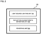
- FIG. 2 is a functional block diagram showing the functions related to the control unit 23.
- the control unit 23 includes a light source lighting unit 231, a reflection characteristic estimation unit 232, and a rendering unit 233.
- the light source lighting unit 231 lights up the light source 24 as necessary in measuring the reflection characteristic.
- the reflection characteristic estimation unit 232 measures the reflection characteristic of the measurement point Sp based on the target information which is the sampling data and the instruction information stored in the storage unit 22. More specifically, the reflection characteristic estimation unit 232 measures the reflection characteristic by machine learning with a neural network. The machine learning inputs the target information, this machine learning inputs the target information, uses the instruction information as an instruction data, and outputs the reflection characteristic (see Section 3). Then, the reflection characteristic of the object S is estimated by preparing a plurality of such target information.
- the rendering unit 233 can generate the computer graphics by implementing the rendering of the computer graphics of the object S having the reflection characteristic.
- the light source 24 is configured to irradiate the incident light L_i to the measurement point Sp which is a part of the object S.
- the incident light L_i is preferably general diffuse white light (having at least an RGB component).
- the light source 24 is lighted on via a lighting circuit (not shown) based on the lighting command signal by the light source lighting unit 231 described above.
- the numerical value relating to the incident light which is one parameter of the target information, is not particularly limited, and the numerical value stored in the storage unit 22 in advance may be adopted.
- the light detection unit 25 is an element that detects light and converts the light into an electric signal, and includes, for example, a photodiode, a photomultiplier tube, a photoconductive element, a CCD, a camera, and the like.
- the light detection unit 25 is configured to detect the reflected light L_o reflected by the incident light L_i irradiating the measurement point Sp which is a part of the object S.
- the detected reflected light L_o is converted into an electric signal and stored in the storage unit 22 as one parameter of the target information, that is, information of numerical values related to the reflected light.
- the display unit 26 is a display that presents information by stimulating the vision of a user.
- information presentation related to other sensations such as a speaker (not shown) and a vibrator (not shown) may be added in combination. More specifically, for example, it may be emphasized in a multi-modal or cross-modal manner depending on the application. With such a configuration, it is possible to extend to an "integrated texture presentation system" that virtually presents the texture of the object S to the observer.
- the display unit 26 can display the reflection characteristic measured by the control unit 23 based on the target information and the instruction information. More specifically, the computer graphics of the object S having the reflection characteristic can be displayed. Further, printing on various objects, color projection, projection mapping, and the like may be performed regarding such computer graphics.
- the information processing device 3 is a so-called workstation, and includes a storage unit 31 and a control unit 32.
- wired communication means such as USB, IEEE1394, Thunderbolt, wired LAN network communication, or wireless communication means such as wireless LAN network communication, mobile communication such as LTE/3G, Bluetooth (registered trademark) communication are included as needed.
- wireless communication means such as USB, IEEE1394, Thunderbolt, wired LAN network communication, or wireless communication means such as wireless LAN network communication, mobile communication such as LTE/3G, Bluetooth (registered trademark) communication are included as needed.
- wireless communication means such as USB, IEEE1394, Thunderbolt, wired LAN network communication, or wireless communication means such as wireless LAN network communication, mobile communication such as LTE/3G, Bluetooth (registered trademark) communication are included as needed.
- wireless communication means such as wireless LAN network communication
- mobile communication such as LTE/3G, Bluetooth (registered trademark) communication
- the storage unit 31 (an example of a "storage medium” in the claims) stores the instruction information described in Section 1.1 and various programs for the control unit 32 to execute, and the like.
- This can be implemented, for example, as a storage device such as a solid state drive (SSD), or as a random access memory (RAM) that stores temporarily necessary information (arguments, arrays, etc.) related to program operations, and combinations thereof are preferable.
- SSD solid state drive
- RAM random access memory
- the instruction information stored in the storage unit 31 may be configured to added data.
- the measurement device 2 connected to the information processing device 3 via the network can acquire the latest teacher information having a richer amount of information. That is, it is expected that the accuracy of the reflection characteristic measured by the control unit 23 in the measurement device 2 will be improved.
- the control unit 32 processes and controls the entire operation related to the information processing device 3.
- the control unit 32 is, for example, a central processing unit (CPU) (not shown).
- the control unit 32 realizes various functions related to the information processing device 3 by reading out a predetermined program stored in the storage unit 31. In this embodiment, the details of these functions will be omitted.
- E_i, x_i, and ⁇ _i are an irradiance, an incident position, and an incident direction of the incident light L_i, respectively.
- L_o, x_o, and ⁇ _ ⁇ are a radiance, a reflection position, and a reflection direction of the reflected light L_o.
- BSSRDFs those that do not depend on the incident position and the reflection position are particularly called a bidirectional reflectance distribution function (BRDF) and are represented as [Equation 2].
- BRDF bidirectional reflectance distribution function
- each variable shall be defined by the Rusinkiewicz coordinate system.
- isotropic is assumed for simplicity. That is, in the present embodiment, the object S is assumed to be a material in which the influence of subsurface scattering can be ignored and isotropic is established, that is, a material whose reflection characteristic is represented by an isotropic BRDF. Further, the function shown in [Equation 4] can be simply described as f ( ⁇ _h, ⁇ _d, ⁇ _d). It should be noted that this is merely an example in the present embodiment, and the present invention is not limited to this.
- Section 3 a machine learning using neural network (an example of "second machine learning” in the claims) will be described in detail.
- an approach of reducing the number of samplings is adopted in order to enable high-speed measurement of the reflection characteristic. This is called the minimum sampling method.
- the sampling direction is not determined adaptively, but a predetermined direction is used. Therefore, it is advantageous in that it is unnecessary to have a movable portion in the configuration of the measurement device 2.
- a neural network is used to provide an estimator (reflection characteristic estimation unit 232) that inputs sampling data and outputs reflection characteristic.
- the reflection characteristic estimation unit 232 introduces a conversion called cos-mapping as represented by [Equation 5]. ⁇ h ⁇ d ⁇ d ⁇ sin ⁇ h , cos ⁇ d , cos 2 ⁇ d
- ⁇ _d -> cos2 ⁇ _ d is a conversion for satisfying the reciprocity of Helmholtz.
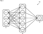
- FIG. 4 is a schematic diagram of the neural network NN.
- Input signals defined by various parameters are input to the first layer L1.
- the input signal is target information including a sampling direction (an example of "coordinate positional relationship” in the claims) and a sampling value (an example of "numerical values relating to incident light and reflected light” in the claims).
- Such an input signal is output from the calculation nodes N_11 to N_13 of the first layer L1 to the calculation nodes N_21 to N_25 of the second layer L2, respectively.
- the value obtained by multiplying the value output from the calculation nodes N_11 to N_13 by the weight w set between the calculation nodes N is input to the calculation nodes N_21 to N_25.
- the calculation nodes N_21 to N_25 add the input values from the calculation nodes N_11 to N_13, and input such a value (or a value obtained by adding a predetermined bias value) to a predetermined activation function.
- the output value of the activation function is propagated to the calculation node N_31, which is the next node.
- a value obtained by multiplying the weight w set between the calculation nodes N_21 to N_25 and the calculation node N_31 by the output value is input to the calculation node N_31.
- the calculation node N_31 adds the input values and outputs the total value as an output signal.
- the calculation node N_31 may add the input values, input the value obtained by adding the bias value to the total value to the activation function, and output the output value as an output signal. As a result, the estimated BRDF is output.
- FIG. 4 is for illustration purposes only, and is not limited thereto.
- the number of nodes in the middle layer is an adjustable parameter, for example, (64,2048), (128,1024), (256,512), (512,256), (1024,128), (2048,64), or the like, preferably (128,1024), (512,256), and more preferably (128,1024).
- the instruction information which is the measurement result of the known reflection characteristic is preferable to adopt the information contained in an appropriate database that collects the isotropic BRDF.
- the number of such samplings is, for example, 1 to 15, preferably 2 to 10, and more preferably 3 to 6. Specifically, for example, it is 1, 2, 3, 4, 5, 6, 7, 8, 9, 10, 11, 12, 13, 14, 15, and it may be within the range between any two of the numerical values exemplified here.
- FIG. 5 when the measurement is performed with the sampling number set to 6, the result as shown in FIG. 6A can be obtained.
- FIG. 6B is a pre-measurement of the true value of the result.
- the sampling direction in such measurement was adopted as shown below.
- ⁇ _i, ⁇ _i, ⁇ _o, and ⁇ _o are shown in FIGS. 3A and 3B , and are frequency representations.
- ⁇ _ i , ⁇ _ i , ⁇ _ o , ⁇ _ o 0 20 180 20 , 0 45 180 45 , 0 60 180 60 , 0 20 0,0 , 0 45 0,0 , 0 60 0,0
- Such a combination is based on a known industrial standard, in which the position of the light source 24 is different in three places and the position of the light detection unit 25 (that is, the detection position of the reflected light) is different in four places (Light sources 24a to 24c and light detection units 25a to 25d in FIG. 5 , respectively).
- the light source 24 and the light detection unit 25 are separately prepared in order to eliminate the movable portion, but a movable portion may be provided so that one light source 24 and the light detection unit 25 can be reused. Comparing FIGS. 6A and 6B , there is no noticeable difference between the two, and the purpose of measuring the reflection characteristic at high speed and high accuracy is achieved.
- FIG. 7 when the measurement is performed with the sampling number set to 3, the result as shown in FIG. 8A can be obtained.
- FIG. 8B is a pre-measurement of the true value of such result.
- the sampling direction in such measurement was adopted as shown below.
- ⁇ _i, ⁇ _i, ⁇ _o, and ⁇ _o are shown in FIGS. 3A and 3B , and are frequency representations.
- ⁇ _ i , ⁇ _ o , ⁇ _ o , ⁇ _ o 0 30 180 30 , 0 26 180 30 , 180 , ⁇ 10 , 180 , 30
- the position of the light source 24 is set to three different positions, and the position of the light detection unit 25 (that is, the detection position of the reflected light) is set to one position (light sources 24d to 24f and light detection unit 25 in FIG. 7 , respectively).
- the light source 24 and the light detection unit 25 are separately prepared in order to eliminate the movable portion, but a movable portion may be provided so that one light source 24 and the light detection unit 25 can be reused. Comparing FIGS. 8A and 8B , there is no noticeable difference between the two, and the purpose of measuring the reflection characteristic at high speed and high accuracy is achieved.
- FIG. 9 is a flowchart of the measurement method. Hereinafter, each step shown in FIG. 9 will be described.
- step S1 an example of the "light irradiation step” in the claims
- the light source lighting unit 231 in the control unit 23 reads out a predetermined program stored in the storage unit 22. Then, the light source 24 is turned on with a specified intensity, whereby the incident light L_i is irradiated to the measurement point Sp in the object S.
- the coordinate position of the light source 24 and the specified intensity are stored in the storage unit 22.
- step S2 an example of the "light detection step” in the claims
- the incident light L_i irradiated to the measurement point Sp in step S1 is reflected, and the light detection unit 25 detects the reflected light L_o as a predetermined intensity.
- the coordinate positions of the light detection unit 25 and the measurement point Sp, and the detected predetermined intensity are stored in the storage unit 22.
- step S3 an example of the "measurement step” in the claims
- the reflection characteristic estimation unit 232 in the control unit 23 measures the reflection characteristic of the object S based on the information stored in the storage unit 23 (see the steps S1 and S2), that is, the target information, and the instruction information previously stored in the storage unit 23. More specifically, the reflection characteristic is estimated by machine learning by a neural network. At this time, the number of combinations of coordinate positional relationships included in the target information is smaller than that of the conventional measurement method of reflection characteristic, and is set in a range of, for example, 1 to 15 or smaller.
- the present embodiment may be further creatively devised according to the following aspects.
- the reflection characteristic obtained from the measurement result may be applied to, for example, an object different from the object S.
- the control unit 32 in the information processing device 3 executes the rendering of the computer graphics of the different object so as to have the reflection characteristic of the object S. That is, applications such as applying the reflection characteristic previously measured to a desired target can be expected in fields such as video content production.
- Section 7 it will be described in more details by using existing gloss meters and color meters as examples.
- the function related to the control unit 23 (more specifically, the reflection characteristic estimation unit 232 and the rendering unit 233) in the measurement device 2 may be performed so as to have the control unit 32 in the information processing device 3. That is, the target information is transmitted from the communication unit 21 in the measurement device 2 to the information processing device 3 via the network, and the control unit 32 in the information processing device 3 may be carried out to measure the reflection characteristic based on such target information and instruction information stored in the storage unit 31.
- the target information previously acquired may be read into the measurement device 2 after the fact, and the reflection characteristic of the object S may be measured.
- the target information may be transmitted to the measurement device 2 via the communication unit 21 described in Section 1, or may be read into via a so-called flash memory (for example, SD memory card, USB memory, memory stick, smart media, compact flash, or the like).
- the target information may read into the parameters included in the target information, or may read into data (for example, an image file or the like) that indirectly includes these parameters.
- the light source 24 and the light detection unit 25 are not essential configurations in the measurement device 2 in such cases.
- the measurement device 2 measures the "glossiness" of the object S. Then, it is carried out so as to convert this into "BRDF" which is a reflection characteristic.
- BRDF reflection characteristic
- a reflectance of 10% is defined as 100% glossiness at an incident angle of 60 degrees
- a reflectance of 5% is defined as 100% glossiness at an incident angle of 20 degrees. That is, it should be noted that glossiness is a physical quantity that depends on reflectance. Therefore, the BRDF, which is a reflection characteristic, can be theoretically calculated from the glossiness in a linear relationship related to the known object S.
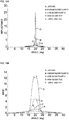
- the graphs of FIGS. 10A and 10B show the distribution of the glossiness of the object S (as described above, since the glossiness is a physical quantity depending on the reflectance, the vertical axis in FIG. 10A is equivalent to the glossiness, that is, it may be replaced with the glossiness) and the BRDF measured by the measurement device 2 (gloss meter).
- the distribution of the reflected light L_o for each reflection angle (light-receiving angle dependence of reflection angle) when the incident light L_i is incident at 20 degrees is shown.
- a to E of each graph relate to the cases where the object S is a leather A, a medium gloss plastic B, a low gloss plastic C, a high gloss tile D, and a low gloss tile E, respectively.
- the spread of the BRDF distribution is wider than the spread of the glossiness distribution that can be measured by the gloss meter. It is presumed that this is because the light detection unit 25 in the measurement device 2 (gloss meter) and the sensor (not shown) that measures the reflection characteristic (BRDF) as instruction information are different. Therefore, by using a machine learning (an example of "first machine learning” in the claims) led by a support vector machine (SVM), the conversion of the BRDF (an example of "partial reflection characteristic” in the claims) is learned from the glossiness, and based on this, the distribution of the BRDF is devised so as to obtain the BRDF distribution.
- SVM support vector machine
- a machine learning model that can estimate the BRDF values of the horizontal axes 5 to 35 degrees in FIG. 10B from the distribution of the glossiness of the horizontal axis 15 to 25 degrees in FIG. 10A .
- FIGS. 11A to 11C show an example in which the glossiness of the object S is measured to estimate the Full BRDF is estimated, and this is output as computer graphics (Stanford bunny) of a different object. Since the gloss meter cannot obtain color information, experiments were carried out with various achromatic colors. In any case, the Full BRDF can be estimated from the glossiness of the object S, and it can be output as a Stanford bunny applied to the computer graphics.
- each of the objects S by the materials A to E has a reflection peak at each.
- the glossiness of each of the objects S made of the materials A to E has dropped to a value close to 0. That is, in the region of 15 degrees (diffuse reflection component), almost no gloss is seen as in the region of 20 degrees (specular reflection component), but it is considered that humans perceive it as a color instead. Therefore, as described above, if a machine learning model that can estimate the BRDF value of the horizontal axis of 5 to 35 degrees in FIG. 10B from the distribution of the glossiness of the horizontal axis of 15 to 25 degrees in FIG. 10A is generated, it is suggested that color information can also be restored when computer graphics are generated.
- the experiment was conducted again by using the measurement device 2 as a gloss meter and a color meter.
- the result is shown in FIG. 12 .
- the glossiness is measured, and the Stanford bunny that restores the reflection characteristic in monochrome using the Full BRDF estimated based on this is output.
- the diffuse reflection component is extracted, and by applying the color measured separately by the measurement device 2 (color meter) to such diffuse reflection component using an existing algorithm related to computer graphics, the Stanford bunny is output including the color information of the object S.
- the control unit 23 is configured to measure the reflection characteristic based on the glossiness of the object S.
- the control unit 23 estimates the partial reflection characteristic, which is a part of the reflection characteristic, by the first machine learning with the glossiness as an input, and estimates the reflection characteristic by the second machine learning with the partial reflection characteristic as an input.
- Such reflection characteristic includes a specular reflection (for example, normal reflection) component representing gloss and a diffuse reflection component associated with color information.
- the measurement device 2 capable of measuring the reflection characteristic of a desired object at higher speed and higher accuracy than before.
- Such measurement device 2 comprises a control unit 23 configured to measure a reflection characteristic of an object S based on target information and instruction information, wherein: the target information is information including a coordinate positional relationship among a light source position of an incident light L_i, a light detection position of a reflected light L_o and a measurement point Sp at the object S, and numerical values related to the incident light L_i and the reflected light L_o, the incident light L_i is light irradiated to the measurement point Sp, the reflected light L_o is light that the incident light L_i is irradiated to the measurement point Sp and then reflected at the measurement point Sp, the instruction information is information related to an existing measurement result of the reflection characteristic, and the number of combinations of the coordinate positional relationship included in the target information is 1 to 15.
- the target information is information including a coordinate positional relationship among a light source position of an incident light L_i, a light detection position of a reflected light L_o and a measurement point Sp at the object S, and numerical values related to
- the measurement system 1 capable of measuring the reflection characteristic of a desired object at higher speed than before.
- Such measurement system 1 comprises a measurement device 2 including a light source 24 irradiates an incident light L_i to a measurement point Sp at the object S, and a light detection unit 25 configured to detect the reflected light L_o that the incident light L_i is irradiated to the measurement point Sp and then reflected at the measurement point Sp; and an information processing device 3, wherein: at least one of the measurement device 2 and the information processing device 3 further comprises a control unit 23/32, the control unit 23/32 is configured to measure a reflection characteristic of the object S based on target information and instruction information, the target information is information including a coordinate positional relationship among the light source 24, the light detection unit 25, and the measurement point Sp, and numerical values related to the incident light L_i and the reflected light L_o, the instruction information is information related to an existing measurement result of the reflection characteristic, and the number of combinations of the coordinate positional relationship included in the target information is 1 to 15, and the measurement device 2 and the information processing device 3 are configured to transmit and receive at least one of the target information, the instruction
- software for implementing the measurement device 2 that can measure the reflection characteristic of the desired object at higher speed than the conventional one as hardware can also be implemented as a program.
- a program may be provided as a non-transitory computer readable medium that can be read by a computer, or may be provided for download from an external server, or may be started by an external computer to perform so-called cloud computing in which each function can be executed on a client terminal.
- Such measurement program is for allowing a computer to perform a predetermined function, wherein: the predetermined function includes a measurement function, a reflection characteristic of an object S is measured based on target information and instruction information by the measurement function, the target information is information including a coordinate positional relationship among a light source position of an incident light L_i, a light detection position of a reflected light L_o and a measurement points Sp at the object S, and numerical values related to the incident light L_i and the reflected light L_o, the incident light L_i is light irradiated to the measurement point Sp, the reflected light L_o is light that the incident light L_i is irradiated to the measurement point Sp and then reflected at the measurement point Sp, the instruction information is information related to an existing measurement result of the reflection characteristic, and the number of combinations of the coordinate positional relationship included in the target information is 1 to 15.
- the measurement device 2 and the measurement system 1 it is possible to carry out a measurement method capable of measuring the reflection characteristic of a desired object at higher speed and a higher accuracy than before.
- Such measurement method comprises a light irradiation step S1 irradiates an incident light L_i to a measurement point at an object S; a light detection step S2 detects a reflected light L_o that the incident light L_i is irradiated to the measurement point Sp and then reflected at the measurement point Sp; and a measurement step S3 measures a reflection characteristic of the object S based on a coordinate positional relationship among a light source position of the incident light L_i, a detection position of the reflected light L_o and the measurement point Sp, numerical values related to the incident light L_i and the reflected light L_o, and an existing measurement result of the reflection characteristic, wherein: the number of combinations of the coordinate positional relationship is 1 to 15.
Landscapes
- Physics & Mathematics (AREA)
- Health & Medical Sciences (AREA)
- Life Sciences & Earth Sciences (AREA)
- Chemical & Material Sciences (AREA)
- Analytical Chemistry (AREA)
- Biochemistry (AREA)
- General Health & Medical Sciences (AREA)
- General Physics & Mathematics (AREA)
- Immunology (AREA)
- Pathology (AREA)
- Investigating Or Analysing Materials By Optical Means (AREA)
Abstract
Description
- The present invention relates to a reflection characteristic measurement device, a measurement system, a measurement program, and a measurement method.
- The "reflection characteristic" is important as an element constituting the visual texture of an object. The reflection characteristic plays an important role in fields such as digital archiving and quality control. When measurement the reflection characteristic, sampling is performed by irradiating incident light to the object and detecting the reflected light. The reflection characteristic is expressed as a function, and the function is estimated from the value sampled in the space formed by the variable. For example, non-Patent
Document 1 discloses a goniometer capable of measuring a reflection characteristic. The goniometer is a measurement device including a light source, a light detection unit, and the like, and is general in that a value in an arbitrary sampling direction can be measured. - [Patent Document 1] Sing Choong Foo, "A genioreflectometer for measuring the spherical reflectance of material for use in illumination", 1997.
- However, when measurement the reflection characteristic by using a measurement device such as a goniometer, it is necessary to sampling the incident light / reflected light from a huge number of directions. For example, although the isotropic bidirectional reflectance distribution function (BRDF), which is relatively simple among the reflection characteristics, has an angular parameter with three degrees of freedom, if sampled at every one degree with respect to each parameter, the number of samples will be enormous as 90 × 90 × 180 = 1,458,000, and the lengthening of the measurement time becomes a problem. Therefore, it can be said that it is required to further shorten the time required for measurement the reflection characteristic.
- The present invention has been made in view of the above circumstances and provides a measurement device, a measurement system, a measurement program, and a measurement method capable of measuring the reflection characteristic of a desired object with a small number of samplings at high speed and high accuracy.
- According to an embodiment of the present invention, there is provided a reflection characteristic measurement device comprising a control unit configured to measure a reflection characteristic of an object based on target information and instruction information, wherein: the target information is information including a coordinate positional relationship among a light source position of an incident light, a light detection position of a reflected light and a measurement point at the object, and numerical values related to the incident light and the reflected light, the incident light is light irradiated to the measurement point, the reflected light is light that the incident light is irradiated to the measurement point and then reflected at the measurement point, the instruction information is information related to an existing measurement result of the reflection characteristic, and the number of combinations of the coordinate positional relationship included in the target information is 1 to 15.
- The measurement device according to the present invention can measure a reflection characteristic of an object based on information (target information) including a coordinate positional relationship (sampling direction) between a light source position, a light detection position and a measurement point, and numerical values (sampling values) related to incident light and reflected light, and information (instruction information) related to an existing measurement result of the reflection characteristic. In particular, it should be noted that the number of combinations (sampling number) of the coordinate positional relationship included in the target information is 1 to 15. According to the measurement device having such a configuration, to measure a desired reflection characteristic in a very short time can be achieved.
-
-
FIG. 1 is a schematic configuration diagram of a measurement system according to the present embodiment. -
FIG. 2 is a functional block diagram of a control unit in the measurement device according to the present embodiment. -
FIGS. 3A and 3B are diagrams showing a Rusinkiewicz coordinate system. -
FIG. 4 is a schematic diagram showing a neural network. -
FIG. 5 is a diagram showing an example in which the number of samplings is 6. -
FIG. 6A is a diagram showing a measurement result of a reflection characteristic when shown inFIG. 5 , andFIG. 6B is a diagram showing a true value of the reflection characteristic when shown inFIG. 5 . -
FIG. 7 is a diagram showing an example in which the number of samplings is 3. -
FIG. 8A is a diagram showing a measurement result of a reflection characteristic when shown inFIG. 7 , andFIG. 8B is a diagram showing a true value of the reflection characteristic when shown inFIG. 7 . -
FIG. 9 is a flowchart showing a measurement method according to the present embodiment. -
FIG. 10A is a diagram showing a distribution of reflectance of an object, that is, a distribution of glossiness (equivalent to reflectance), andFIG. 10B is a diagram showing a distribution of BRDF of the object. -
FIG. 11A is an example in which the glossiness of an object (white / achromatic color) is measured, a Full BRDF is estimated, and this is output as computer graphics (Stanford bunny) of a different object,FIG. 11B is an example of measurement the glossiness of an object (when both white and non-white include achromatic colors), estimating the Full BRDF, and outputting this as computer graphics (Stanford bunny) of different objects, andFIG. 11C is an example in which the glossiness of an object (non-white / achromatic color) is measured to estimate the Full BRDF, and this is output as computer graphics (Stanford bunny) of a different object. -
FIG. 12 is an example in which the glossiness of an object (chromatic color) is measured, a Full BRDF is estimated, and this is output as computer graphics (Stanford bunny) of a different object including color information. - Hereinafter, embodiments of the present invention will be described with reference to the drawings. Various features described in the embodiment below can be combined with each other. Especially in the present specification, the "unit" may include, for instance, a combination of hardware resources implemented by circuits in a broad sense and information processing of software that can be concretely realized by these hardware resources. Further, although various information is performed in the present embodiments, these information are represented by high and low signal values as a bit set of binary numbers composed of 0 or 1, and communication/calculation can be executed on a circuit in a broad sense.
- Further, a circuit in a broad sense is a circuit realized by at least appropriately combining a circuit, a circuitry, a processor, a memory, and the like. That is, an application special integrated circuit (ASIC), a programmable logic device (for example, a simple programmable logic device (SPLD)), a complex programmable logic device (CLPD), a field programmable gate array (FPGA), and the like.
-
FIG. 1 is a schematic configuration diagram of ameasurement system 1 according to the present embodiment. Themeasurement system 1 is configured to measure a reflection characteristic of an object S. As shown inFIG. 1 , themeasurement system 1 includes ameasurement device 2 and aninformation processing device 3, both of which are connected to each other via a network. In Sections 1.1 to 1.2, themeasurement device 2 and theinformation processing device 3 will be described respectively. - The
measurement device 2 includes acommunication unit 21, astorage unit 22, acontrol unit 23, alight source 24, alight detection unit 25, and adisplay unit 26, and these components electrically communicate with each other in themeasurement device 2 via acommunication bus 20. Hereinafter, each component will be further described. - Although wired communication means such as USB, IEEE1394, Thunderbolt, or wired LAN network communication are preferable, the
communication unit 21 may also include wireless LAN network communication, mobile communication such as LTE/3G, Bluetooth (registered trademark) communication and the like as necessary. That is, it is more preferable to carry out as a set of these plurality of communication means. Further, the reflection characteristic may be measured while communicating with theinformation processing device 3 described later, which is an external device, via thecommunication unit 21, or may be independently operated in an offline environment. Further, the measured reflection characteristic may be transmitted to theinformation processing apparatus 3. - The storage unit 22 (an example of a "storage medium" in the claims) stores the information defined by the above description. For example, the
storage unit 22 stores target information, instruction information, various programs for thecontrol unit 23 to execute, and the like. This is, for example, as a storage device such as a solid state drive (SSD), or as a random access memory (RAM) that stores temporarily necessary information (arguments, arrays, etc.) related to program operations. Moreover, combinations thereof may be used. - The target information is sampling data required for measuring the reflection characteristic of the object S and is determined by a coordinate positional relationship among the light source 24 (incident light), the light detection unit 25 (reflected light) and the measurement point Sp which is a part of the object S, which will be described later, and numerical values (radiant intensity, etc.) related to the incident light and the reflected light. Further, the instruction information is information related to an existing measurement result of the reflection characteristic, and is instruction data employed in the estimation of the reflection characteristic by using machine learning described later. In general, the instruction information may be, for example, information including various parameters machine-learned based on known measurement results, and may be information including the measurement results themselves. The instruction information may be stored in the
storage unit 22 in advance when implementing themeasurement device 2, but the updated data of the instruction information may be downloaded from theinformation processing device 3 via thecommunication unit 21 and may be configured to be memorable if necessary. Furthermore, the updated data of the instruction information to be downloaded may be all or a part of the instruction data stored in theinformation processing device 3. - The
control unit 23 processes and controls the overall operation related to themeasurement device 2. Thecontrol unit 23 is, for example, a central processing unit (CPU) (not shown). Thecontrol unit 23 realizes various functions related to themeasurement device 2 by reading out a predetermined program stored in thestorage unit 22. Although it is shown as asingle control unit 23 inFIG. 1 , it is not limited to this, and it may be implemented so as to have a plurality of control units 23 (dedicated chips, etc.) for each function. Moreover, combinations thereof may be used. -
FIG. 2 is a functional block diagram showing the functions related to thecontrol unit 23. Thecontrol unit 23 includes a lightsource lighting unit 231, a reflectioncharacteristic estimation unit 232, and arendering unit 233. The lightsource lighting unit 231 lights up thelight source 24 as necessary in measuring the reflection characteristic. The reflectioncharacteristic estimation unit 232 measures the reflection characteristic of the measurement point Sp based on the target information which is the sampling data and the instruction information stored in thestorage unit 22. More specifically, the reflectioncharacteristic estimation unit 232 measures the reflection characteristic by machine learning with a neural network. The machine learning inputs the target information, this machine learning inputs the target information, uses the instruction information as an instruction data, and outputs the reflection characteristic (see Section 3). Then, the reflection characteristic of the object S is estimated by preparing a plurality of such target information. Therendering unit 233 can generate the computer graphics by implementing the rendering of the computer graphics of the object S having the reflection characteristic. - The
light source 24 is configured to irradiate the incident light L_i to the measurement point Sp which is a part of the object S. The incident light L_i is preferably general diffuse white light (having at least an RGB component). Thelight source 24 is lighted on via a lighting circuit (not shown) based on the lighting command signal by the lightsource lighting unit 231 described above. Further, the numerical value relating to the incident light, which is one parameter of the target information, is not particularly limited, and the numerical value stored in thestorage unit 22 in advance may be adopted. - The
light detection unit 25 is an element that detects light and converts the light into an electric signal, and includes, for example, a photodiode, a photomultiplier tube, a photoconductive element, a CCD, a camera, and the like. Here, thelight detection unit 25 is configured to detect the reflected light L_o reflected by the incident light L_i irradiating the measurement point Sp which is a part of the object S. The detected reflected light L_o is converted into an electric signal and stored in thestorage unit 22 as one parameter of the target information, that is, information of numerical values related to the reflected light. - The
display unit 26 is a display that presents information by stimulating the vision of a user. Of course, in addition to thedisplay unit 26, information presentation related to other sensations such as a speaker (not shown) and a vibrator (not shown) may be added in combination. More specifically, for example, it may be emphasized in a multi-modal or cross-modal manner depending on the application. With such a configuration, it is possible to extend to an "integrated texture presentation system" that virtually presents the texture of the object S to the observer. In particular, thedisplay unit 26 can display the reflection characteristic measured by thecontrol unit 23 based on the target information and the instruction information. More specifically, the computer graphics of the object S having the reflection characteristic can be displayed. Further, printing on various objects, color projection, projection mapping, and the like may be performed regarding such computer graphics. - As shown in
FIG. 1 , theinformation processing device 3 is a so-called workstation, and includes astorage unit 31 and acontrol unit 32. Of course, wired communication means such as USB, IEEE1394, Thunderbolt, wired LAN network communication, or wireless communication means such as wireless LAN network communication, mobile communication such as LTE/3G, Bluetooth (registered trademark) communication are included as needed. Via such a communication means, it is possible to communicate with themeasurement device 2 via such a communication means. Hereinafter, each component related to theinformation processing device 3 will be further described. - The storage unit 31 (an example of a "storage medium" in the claims) stores the instruction information described in Section 1.1 and various programs for the
control unit 32 to execute, and the like. This can be implemented, for example, as a storage device such as a solid state drive (SSD), or as a random access memory (RAM) that stores temporarily necessary information (arguments, arrays, etc.) related to program operations, and combinations thereof are preferable. - Although not particularly limited, the instruction information stored in the
storage unit 31 may be configured to added data. As a result, themeasurement device 2 connected to theinformation processing device 3 via the network can acquire the latest teacher information having a richer amount of information. That is, it is expected that the accuracy of the reflection characteristic measured by thecontrol unit 23 in themeasurement device 2 will be improved. - The
control unit 32 processes and controls the entire operation related to theinformation processing device 3. Thecontrol unit 32 is, for example, a central processing unit (CPU) (not shown). Thecontrol unit 32 realizes various functions related to theinformation processing device 3 by reading out a predetermined program stored in thestorage unit 31. In this embodiment, the details of these functions will be omitted. - In
Section 2, one example of the reflection characteristic measured by themeasurement system 1 according to the present embodiment will be described in detail. - In the first place, as a function expressing the reflection characteristic, there is an outgoing bidirectional scattering surface reflectance distribution function (BSSRDF), which is specifically expressed as [Equation 1].

- Here, E_i, x_i, and ω_i (ϕ_i and θ_i) are an irradiance, an incident position, and an incident direction of the incident light L_i, respectively. Further, L_o, x_o, and ω_ο (ϕ_o and θ_o) are a radiance, a reflection position, and a reflection direction of the reflected light L_o. Among the BSSRDFs, those that do not depend on the incident position and the reflection position are particularly called a bidirectional reflectance distribution function (BRDF) and are represented as [Equation 2].

- As a method of adopting the coordinate system of BRDF, in addition to the coordinate system based on the directions of the incident light L_i and the reflected light L_o as described above, the Rusinkiewicz coordinate system defined based on the half vector is known. The half vector ω_h is represented as [Equation 3].

- Assuming isotropic property, that is, the property that the reflection characteristic is invariant with respect to rotation about the normal line n, the degree of freedom of ω_h is 1, and it becomes a three-variable function with θ_h, θ_d, and ϕ_d as variables as shown in [Equation 4]. However, as shown in
FIGS. 3A and 3B , each variable shall be defined by the Rusinkiewicz coordinate system.
- Although anisotropic reflection is found in materials such as hairline-processed metals, gems, and woven fabrics, here, isotropic is assumed for simplicity. That is, in the present embodiment, the object S is assumed to be a material in which the influence of subsurface scattering can be ignored and isotropic is established, that is, a material whose reflection characteristic is represented by an isotropic BRDF. Further, the function shown in [Equation 4] can be simply described as f (θ_h, θ_d, ϕ_d). It should be noted that this is merely an example in the present embodiment, and the present invention is not limited to this.
- In
Section 3, a machine learning using neural network (an example of "second machine learning" in the claims) will be described in detail. In the measurement of the reflection characteristic according to the present embodiment, an approach of reducing the number of samplings (an example of the "number of combinations" in the claims) is adopted in order to enable high-speed measurement of the reflection characteristic. This is called the minimum sampling method. Further, in order to achieve high speed, the sampling direction is not determined adaptively, but a predetermined direction is used. Therefore, it is advantageous in that it is unnecessary to have a movable portion in the configuration of themeasurement device 2. - When the minimum sampling is adopted, since it is necessary to estimate the data in the direction not sampled, the improvement of the accuracy is an issue. In the present embodiment, a neural network is used to provide an estimator (reflection characteristic estimation unit 232) that inputs sampling data and outputs reflection characteristic. By designing the estimator in this way, since model generation and model parameter estimation are optimized at the same time, the performance is expected to improve.
- Further, since the reflection characteristic model specialized for the sampling direction is learned, there is no strong and weak sampling direction derived from the reflection characteristic model, and an estimator can be freely constructed with respect to the sampling direction. Therefore, it is considered that the function of the existing gloss meter can be expanded to provide a more
compact measurement device 2. InSection 6, it will be described in detail. - Here, in order to improve the estimation accuracy, the reflection
characteristic estimation unit 232 introduces a conversion called cos-mapping as represented by [Equation 5].
- The conversion of ϕ_d -> cos2ϕ_d is a conversion for satisfying the reciprocity of Helmholtz. Further, θ_h -> sin θ_h and θ_d -> cos θ_d are transformations that allow a more detailed look at the specular reflection near θ_h = 0 and the Fresnel reflection near θ_d = π / 2. It is considered that such a transformation can improve the accuracy of machine learning by the neural network.
-
FIG. 4 is a schematic diagram of the neural network NN. Input signals defined by various parameters are input to the first layer L1. Here, the input signal is target information including a sampling direction (an example of "coordinate positional relationship" in the claims) and a sampling value (an example of "numerical values relating to incident light and reflected light" in the claims). Such an input signal is output from the calculation nodes N_11 to N_13 of the first layer L1 to the calculation nodes N_21 to N_25 of the second layer L2, respectively. At this time, the value obtained by multiplying the value output from the calculation nodes N_11 to N_13 by the weight w set between the calculation nodes N is input to the calculation nodes N_21 to N_25. - The calculation nodes N_21 to N_25 add the input values from the calculation nodes N_11 to N_13, and input such a value (or a value obtained by adding a predetermined bias value) to a predetermined activation function. As the activation function, for example, the one represented by [Equation 6] is used.

- Then, the output value of the activation function is propagated to the calculation node N_31, which is the next node. At this time, a value obtained by multiplying the weight w set between the calculation nodes N_21 to N_25 and the calculation node N_31 by the output value is input to the calculation node N_31. The calculation node N_31 adds the input values and outputs the total value as an output signal. At this time, the calculation node N_31 may add the input values, input the value obtained by adding the bias value to the total value to the activation function, and output the output value as an output signal. As a result, the estimated BRDF is output.
- It should be noted that what is shown in
FIG. 4 is for illustration purposes only, and is not limited thereto. For example, in the present embodiment, it is conceivable to adopt one having two intermediate layers. The number of nodes in the middle layer is an adjustable parameter, for example, (64,2048), (128,1024), (256,512), (512,256), (1024,128), (2048,64), or the like, preferably (128,1024), (512,256), and more preferably (128,1024). Further, the instruction information which is the measurement result of the known reflection characteristic is preferable to adopt the information contained in an appropriate database that collects the isotropic BRDF. - By using the
measurement system 1 as described above, it is possible to reduce the number of samplings and measure the BRDF, that is, the reflection characteristic, at higher speed and higher accuracy than before. The number of such samplings is, for example, 1 to 15, preferably 2 to 10, and more preferably 3 to 6. Specifically, for example, it is 1, 2, 3, 4, 5, 6, 7, 8, 9, 10, 11, 12, 13, 14, 15, and it may be within the range between any two of the numerical values exemplified here. For example, as shown inFIG. 5 , when the measurement is performed with the sampling number set to 6, the result as shown inFIG. 6A can be obtained. Note thatFIG. 6B is a pre-measurement of the true value of the result. The sampling direction in such measurement was adopted as shown below. However, ϕ_i, θ_i, ϕ_o, and θ_o are shown inFIGS. 3A and 3B , and are frequency representations.
- Such a combination is based on a known industrial standard, in which the position of the
light source 24 is different in three places and the position of the light detection unit 25 (that is, the detection position of the reflected light) is different in four places (Light sources 24a to 24c andlight detection units 25a to 25d inFIG. 5 , respectively). Of course, this is just an example and not limited to this. It is preferable that thelight source 24 and thelight detection unit 25 are separately prepared in order to eliminate the movable portion, but a movable portion may be provided so that onelight source 24 and thelight detection unit 25 can be reused. ComparingFIGS. 6A and 6B , there is no noticeable difference between the two, and the purpose of measuring the reflection characteristic at high speed and high accuracy is achieved. - Further, as shown in
FIG. 7 , when the measurement is performed with the sampling number set to 3, the result as shown inFIG. 8A can be obtained. Note thatFIG. 8B is a pre-measurement of the true value of such result. The sampling direction in such measurement was adopted as shown below. However, ϕ_i, θ_i, ϕ_o, and θ_o are shown inFIGS. 3A and 3B , and are frequency representations.
- Such a combination is inspired and uniquely set based on the above-mentioned industrial standard, the position of the
light source 24 is set to three different positions, and the position of the light detection unit 25 (that is, the detection position of the reflected light) is set to one position (light sources 24d to 24f andlight detection unit 25 inFIG. 7 , respectively). Of course, this is just an example and not limited to this. It is preferable that thelight source 24 and thelight detection unit 25 are separately prepared in order to eliminate the movable portion, but a movable portion may be provided so that onelight source 24 and thelight detection unit 25 can be reused. ComparingFIGS. 8A and 8B , there is no noticeable difference between the two, and the purpose of measuring the reflection characteristic at high speed and high accuracy is achieved. - In
Section 5, an example of a measurement method of the reflection characteristic of the object S using themeasurement device 2 described above will be handled.FIG. 9 is a flowchart of the measurement method. Hereinafter, each step shown inFIG. 9 will be described. - In step S1 (an example of the "light irradiation step" in the claims), in the
measurement device 2, the lightsource lighting unit 231 in thecontrol unit 23 reads out a predetermined program stored in thestorage unit 22. Then, thelight source 24 is turned on with a specified intensity, whereby the incident light L_i is irradiated to the measurement point Sp in the object S. The coordinate position of thelight source 24 and the specified intensity are stored in thestorage unit 22. - In step S2 (an example of the "light detection step" in the claims), the incident light L_i irradiated to the measurement point Sp in step S1 is reflected, and the
light detection unit 25 detects the reflected light L_o as a predetermined intensity. The coordinate positions of thelight detection unit 25 and the measurement point Sp, and the detected predetermined intensity are stored in thestorage unit 22. - In step S3 (an example of the "measurement step" in the claims), the reflection
characteristic estimation unit 232 in thecontrol unit 23 measures the reflection characteristic of the object S based on the information stored in the storage unit 23 (see the steps S1 and S2), that is, the target information, and the instruction information previously stored in thestorage unit 23. More specifically, the reflection characteristic is estimated by machine learning by a neural network. At this time, the number of combinations of coordinate positional relationships included in the target information is smaller than that of the conventional measurement method of reflection characteristic, and is set in a range of, for example, 1 to 15 or smaller. - The present embodiment may be further creatively devised according to the following aspects.
- First, the reflection characteristic obtained from the measurement result may be applied to, for example, an object different from the object S. In other words, the
control unit 32 in theinformation processing device 3 executes the rendering of the computer graphics of the different object so as to have the reflection characteristic of the object S. That is, applications such as applying the reflection characteristic previously measured to a desired target can be expected in fields such as video content production. In Section 7, it will be described in more details by using existing gloss meters and color meters as examples. - Second, the function related to the control unit 23 (more specifically, the reflection
characteristic estimation unit 232 and the rendering unit 233) in themeasurement device 2 may be performed so as to have thecontrol unit 32 in theinformation processing device 3. That is, the target information is transmitted from thecommunication unit 21 in themeasurement device 2 to theinformation processing device 3 via the network, and thecontrol unit 32 in theinformation processing device 3 may be carried out to measure the reflection characteristic based on such target information and instruction information stored in thestorage unit 31. - Third, the target information previously acquired may be read into the
measurement device 2 after the fact, and the reflection characteristic of the object S may be measured. In such a case, the target information may be transmitted to themeasurement device 2 via thecommunication unit 21 described inSection 1, or may be read into via a so-called flash memory (for example, SD memory card, USB memory, memory stick, smart media, compact flash, or the like). Further, the target information may read into the parameters included in the target information, or may read into data (for example, an image file or the like) that indirectly includes these parameters. Of course, it should be noted that thelight source 24 and thelight detection unit 25 are not essential configurations in themeasurement device 2 in such cases. - In the present section, an example in which a gloss meter or a color meter is used as the
measurement device 2 will be described in detail. - The measurement device 2 (gloss meter) measures the "glossiness" of the object S. Then, it is carried out so as to convert this into "BRDF" which is a reflection characteristic. According to the JIS standard, on a glass surface having a refractive index of 1.567, it is stipulated that a reflectance of 10% is defined as 100% glossiness at an incident angle of 60 degrees, and a reflectance of 5% is defined as 100% glossiness at an incident angle of 20 degrees. That is, it should be noted that glossiness is a physical quantity that depends on reflectance. Therefore, the BRDF, which is a reflection characteristic, can be theoretically calculated from the glossiness in a linear relationship related to the known object S.
- The graphs of
FIGS. 10A and 10B show the distribution of the glossiness of the object S (as described above, since the glossiness is a physical quantity depending on the reflectance, the vertical axis inFIG. 10A is equivalent to the glossiness, that is, it may be replaced with the glossiness) and the BRDF measured by the measurement device 2 (gloss meter). Here, the distribution of the reflected light L_o for each reflection angle (light-receiving angle dependence of reflection angle) when the incident light L_i is incident at 20 degrees is shown. Further, A to E of each graph relate to the cases where the object S is a leather A, a medium gloss plastic B, a low gloss plastic C, a high gloss tile D, and a low gloss tile E, respectively. Based on such results, it is confirmed that the spread of the BRDF distribution is wider than the spread of the glossiness distribution that can be measured by the gloss meter. It is presumed that this is because thelight detection unit 25 in the measurement device 2 (gloss meter) and the sensor (not shown) that measures the reflection characteristic (BRDF) as instruction information are different. Therefore, by using a machine learning (an example of "first machine learning" in the claims) led by a support vector machine (SVM), the conversion of the BRDF (an example of "partial reflection characteristic" in the claims) is learned from the glossiness, and based on this, the distribution of the BRDF is devised so as to obtain the BRDF distribution. Especially considering the spread of the distribution, it is preferable to, for instance, generate a machine learning model that can estimate the BRDF values of thehorizontal axes 5 to 35 degrees inFIG. 10B from the distribution of the glossiness of thehorizontal axis 15 to 25 degrees inFIG. 10A . - That is, by combining a conversion that inputs glossiness and outputs BRDF (explained as described above in this section) and a conversion that inputs the BRDF and outputs BRDF (Full BRDF) of the entire object S (explained as a superordinate concept as "reflection characteristic" in
Sections 1 to 5), the glossiness can be measured and the Full BRDF can be obtained therefrom. This can be applied to the rendering of computer graphics of different objects so as to have the BRDF of the object S described as a modification. -
FIGS. 11A to 11C show an example in which the glossiness of the object S is measured to estimate the Full BRDF is estimated, and this is output as computer graphics (Stanford bunny) of a different object. Since the gloss meter cannot obtain color information, experiments were carried out with various achromatic colors. In any case, the Full BRDF can be estimated from the glossiness of the object S, and it can be output as a Stanford bunny applied to the computer graphics. - In
FIG. 10A , for example, referring to the vicinity of 20 degrees on the horizontal axis, since normal reflection (specular reflection) is naturally performed, each of the objects S by the materials A to E has a reflection peak at each. On the other hand, referring to the vicinity of 15 degrees, it is confirmed that the glossiness of each of the objects S made of the materials A to E has dropped to a value close to 0. That is, in the region of 15 degrees (diffuse reflection component), almost no gloss is seen as in the region of 20 degrees (specular reflection component), but it is considered that humans perceive it as a color instead. Therefore, as described above, if a machine learning model that can estimate the BRDF value of the horizontal axis of 5 to 35 degrees inFIG. 10B from the distribution of the glossiness of the horizontal axis of 15 to 25 degrees inFIG. 10A is generated, it is suggested that color information can also be restored when computer graphics are generated. - Therefore, the experiment was conducted again by using the
measurement device 2 as a gloss meter and a color meter. The result is shown inFIG. 12 . By measuring the object S with the measurement device 2 (gloss meter), the glossiness is measured, and the Stanford bunny that restores the reflection characteristic in monochrome using the Full BRDF estimated based on this is output. From here, the diffuse reflection component is extracted, and by applying the color measured separately by the measurement device 2 (color meter) to such diffuse reflection component using an existing algorithm related to computer graphics, the Stanford bunny is output including the color information of the object S. - By combining the existing gloss meter and the color meter as the
measurement device 2 in this way, it is possible to perform rendering of computer graphics of different objects so as to have the reflection characteristic of the object S. It should be noted that this is just an experiment, and it is more preferable to newly implement ameasurement device 2 capable of measuring both glossiness and color. - That is, the following matters should be noted. The
control unit 23 is configured to measure the reflection characteristic based on the glossiness of the object S. Thecontrol unit 23 estimates the partial reflection characteristic, which is a part of the reflection characteristic, by the first machine learning with the glossiness as an input, and estimates the reflection characteristic by the second machine learning with the partial reflection characteristic as an input. Such reflection characteristic includes a specular reflection (for example, normal reflection) component representing gloss and a diffuse reflection component associated with color information. - As described above, according to the present embodiment, it is possible to implement the
measurement device 2 capable of measuring the reflection characteristic of a desired object at higher speed and higher accuracy than before. -
Such measurement device 2 comprises acontrol unit 23 configured to measure a reflection characteristic of an object S based on target information and instruction information, wherein: the target information is information including a coordinate positional relationship among a light source position of an incident light L_i, a light detection position of a reflected light L_o and a measurement point Sp at the object S, and numerical values related to the incident light L_i and the reflected light L_o, the incident light L_i is light irradiated to the measurement point Sp, the reflected light L_o is light that the incident light L_i is irradiated to the measurement point Sp and then reflected at the measurement point Sp, the instruction information is information related to an existing measurement result of the reflection characteristic, and the number of combinations of the coordinate positional relationship included in the target information is 1 to 15. - Further, it is also possible to implement the
measurement system 1 capable of measuring the reflection characteristic of a desired object at higher speed than before. -
Such measurement system 1 comprises ameasurement device 2 including alight source 24 irradiates an incident light L_i to a measurement point Sp at the object S, and alight detection unit 25 configured to detect the reflected light L_o that the incident light L_i is irradiated to the measurement point Sp and then reflected at the measurement point Sp; and aninformation processing device 3, wherein: at least one of themeasurement device 2 and theinformation processing device 3 further comprises acontrol unit 23/32, thecontrol unit 23/32 is configured to measure a reflection characteristic of the object S based on target information and instruction information, the target information is information including a coordinate positional relationship among thelight source 24, thelight detection unit 25, and the measurement point Sp, and numerical values related to the incident light L_i and the reflected light L_o, the instruction information is information related to an existing measurement result of the reflection characteristic, and the number of combinations of the coordinate positional relationship included in the target information is 1 to 15, and themeasurement device 2 and theinformation processing device 3 are configured to transmit and receive at least one of the target information, the instruction information, and information including the reflection characteristic to and from each other via a network. - Then, software for implementing the
measurement device 2 that can measure the reflection characteristic of the desired object at higher speed than the conventional one as hardware can also be implemented as a program. Then, such a program may be provided as a non-transitory computer readable medium that can be read by a computer, or may be provided for download from an external server, or may be started by an external computer to perform so-called cloud computing in which each function can be executed on a client terminal. - Such measurement program is for allowing a computer to perform a predetermined function, wherein: the predetermined function includes a measurement function, a reflection characteristic of an object S is measured based on target information and instruction information by the measurement function, the target information is information including a coordinate positional relationship among a light source position of an incident light L_i, a light detection position of a reflected light L_o and a measurement points Sp at the object S, and numerical values related to the incident light L_i and the reflected light L_o, the incident light L_i is light irradiated to the measurement point Sp, the reflected light L_o is light that the incident light L_i is irradiated to the measurement point Sp and then reflected at the measurement point Sp, the instruction information is information related to an existing measurement result of the reflection characteristic, and the number of combinations of the coordinate positional relationship included in the target information is 1 to 15.
- Further, by using the
measurement device 2 and themeasurement system 1, it is possible to carry out a measurement method capable of measuring the reflection characteristic of a desired object at higher speed and a higher accuracy than before. - Such measurement method comprises a light irradiation step S1 irradiates an incident light L_i to a measurement point at an object S; a light detection step S2 detects a reflected light L_o that the incident light L_i is irradiated to the measurement point Sp and then reflected at the measurement point Sp; and a measurement step S3 measures a reflection characteristic of the object S based on a coordinate positional relationship among a light source position of the incident light L_i, a detection position of the reflected light L_o and the measurement point Sp, numerical values related to the incident light L_i and the reflected light L_o, and an existing measurement result of the reflection characteristic, wherein: the number of combinations of the coordinate positional relationship is 1 to 15.
- Finally, various embodiments of the present invention have been described, but these are presented as examples and are not intended to limit the scope of the invention. The novel embodiment can be implemented in various other forms, and various omissions, replacements, and changes can be made without departing from the abstract of the invention. The embodiment and its modifications are included in the scope and abstract of the invention and are included in the scope of the invention described in the claims and the equivalent scope thereof.
-
- 1
- Measurement system
- 2
- Measurement device
- 20
- Communication bus
- 21
- Communication unit
- 22
- Storage unit
- 23
- Control unit
- 231
- Light source lighting unit
- 232
- Reflection characteristic estimation unit
- 233
- Rendering unit
- 24
- Light source
- 24a
- Light source
- 24b
- Light source
- 24c
- Light source
- 24d
- Light source
- 24e
- Light source
- 24f
- Light source
- 25
- Light detection unit
- 25a
- Light detection unit
- 25b
- Light detection unit
- 25c
- Light detection unit
- 25d
- Light detection unit
- 26
- Display unit
- 3
- Information processing device
- 31
- Storage unit
- 32
- Control unit
- L_i
- Incident light
- L_o
- Reflected light
Claims (16)
- A reflection characteristic measurement device, comprising:
a control unit configured to measure a reflection characteristic of an object based on target information and instruction information, wherein:the target information is information including a coordinate positional relationship among a light source position of an incident light, a light detection position of a reflected light and a measurement point at the object, and numerical values related to the incident light and the reflected light,the incident light is light irradiated to the measurement point, the reflected light is light that the incident light is irradiated to the measurement point and then reflected at the measurement point,the instruction information is information related to an existing measurement result of the reflection characteristic, andthe number of combinations of the coordinate positional relationship included in the target information is 1 to 15. - The measurement device according to Claim 1, further comprising:a light source configured to irradiate the incident light, anda light detection unit configured to detect the reflected light.
- The measurement device according to Claim 1 or 2, further comprising:
a communication unit configured to output at least one of the target information, the instruction information, and the information including the reflection characteristic to an external apparatus. - The measurement device according to any one of Claims 1 to 3, wherein:
the control unit is configured to generate a computer graphics based on the reflection characteristic. - The measurement device according to any one of Claims 1 to 4, wherein:
the number of combinations is 2 to 10. - The measurement device according to any one of Claims 1 to 5, wherein:
the number of combinations is 3 to 6. - The measurement device according to any one of Claims 1 to 6, wherein:the control unit estimates the reflection characteristic by a machine learning, andthe machine learning inputs the target information, uses the instruction information as an instruction data, and outputs the reflection characteristic.
- The measurement device according to Claim 7, wherein:
the reflection characteristic is expressed as a function f (θ_h, θ_d, ϕ_d) having θ_h, θ_d, and ϕ_d as variables in the Rushinkieviz coordinate system, in the machine learning, processes of converting ϕ_d to cos2ϕ_d, θ_h to sinθ_h, and θ_d to cosθ_d are included. - The measurement device according to any one of Claims 1 to 8, wherein:
the control unit is configured to measure the reflection characteristic based on a glossiness of the object. - The measurement device according to Claim 9, wherein:the control unit estimates the partial reflection characteristic that is a part of the reflection characteristic by first machine learning using the glossiness as an input, andthe second control unit estimates the reflection characteristic by second machine learning using the partial reflection characteristic as an input.
- The measurement device according to any one of Claims 1 to 10, wherein:
the reflection characteristic includes a specular reflection component representing gloss and a diffuse reflection component associated with color information. - A reflection characteristic measurement system, comprising:a measurement device including a light source irradiates an incident light to a measurement point at the object, and a light detection unit configured to detect the reflected light that the incident light is irradiated to the measurement point and then reflected at the measurement point; andan information processing device, wherein:at least one of the measurement device and the information processing device further comprises a control unit,the control unit is configured to measure a reflection characteristic of the object based on target information and instruction information,the target information is information including a coordinate positional relationship among the light source, the light detection unit, and the measurement point, and numerical values related to the incident light and the reflected light, the instruction information is information related to an existing measurement result of the reflection characteristic, and the number of combinations of the coordinate positional relationship included in the target information is 1 to 15, andthe measurement device and the information processing device are configured to transmit and receive at least one of the target information, the instruction information, and information including the reflection characteristic to and from each other via a network.
- The measurement system according to Claim 12, wherein:
the control unit in the information processing device is configured to generate a computer graphics based on the reflection characteristic. - The measurement system according to Claim 13, wherein:
the control unit in the information processing device is configured to apply the reflection characteristic to an object different from the object and to generate a computer graphics of the object. - A measurement program for allowing a computer to perform a predetermined function, wherein:the predetermined function includes a measurement function,a reflection characteristic of an object is measured based on target information and instruction information by the measurement function,the target information is information including a coordinate positional relationship among a light source position of an incident light, a light detection position of a reflected light and a measurement point at the object, and numerical values related to the incident light and the reflected light,the incident light is light irradiated to the measurement point, the reflected light is light that the incident light is irradiated to the measurement point and then reflected at the measurement point,the instruction information is information related to an existing measurement result of the reflection characteristic, andthe number of combinations of the coordinate positional relationship included in the target information is 1 to 15.
- A reflection characteristic measurement method, comprising:a light irradiation step irradiates an incident light to a measurement point at an object;a light detection step detects a reflected light that the incident light is irradiated to the measurement point and then reflected at the measurement point; anda measurement step measures a reflection characteristic of the object based on a coordinate positional relationship among a light source position of the incident light, a detection position of the reflected light and the measurement point, numerical values related to the incident light and the reflected light, and an existing measurement result of the reflection characteristic, wherein:
the number of combinations of the coordinate positional relationship is 1 to 15.
Applications Claiming Priority (2)
| Application Number | Priority Date | Filing Date | Title |
|---|---|---|---|
| JP2018140773 | 2018-07-26 | ||
| PCT/JP2019/029375 WO2020022473A1 (en) | 2018-07-26 | 2019-07-26 | Measurement device, measurement system, measurement program, and measurement method |
Publications (2)
| Publication Number | Publication Date |
|---|---|
| EP3812743A1 true EP3812743A1 (en) | 2021-04-28 |
| EP3812743A4 EP3812743A4 (en) | 2022-03-09 |
Family
ID=69181027
Family Applications (1)
| Application Number | Title | Priority Date | Filing Date |
|---|---|---|---|
| EP19840527.6A Withdrawn EP3812743A4 (en) | 2018-07-26 | 2019-07-26 | MEASUREMENT DEVICE, MEASUREMENT SYSTEM, MEASUREMENT PROGRAM AND MEASUREMENT PROCEDURE |
Country Status (5)
| Country | Link |
|---|---|
| US (1) | US11874225B2 (en) |
| EP (1) | EP3812743A4 (en) |
| JP (1) | JP6982910B2 (en) |
| CN (1) | CN112771367B (en) |
| WO (1) | WO2020022473A1 (en) |
Families Citing this family (2)
| Publication number | Priority date | Publication date | Assignee | Title |
|---|---|---|---|---|
| CN114586330B (en) * | 2019-11-13 | 2023-04-21 | 华为技术有限公司 | Multi-hypothesis classification of color constancy |
| CN115684092B (en) * | 2022-10-21 | 2025-05-16 | 上海星宙之形科技有限公司 | Method and system for measuring bidirectional reflectance distribution function of digital asset material surface |
Family Cites Families (16)
| Publication number | Priority date | Publication date | Assignee | Title |
|---|---|---|---|---|
| US4704121A (en) | 1983-09-28 | 1987-11-03 | Nimbus, Inc. | Anti-thrombogenic blood pump |
| JP2705842B2 (en) | 1989-09-26 | 1998-01-28 | 川崎製鉄株式会社 | Method and apparatus for measuring surface properties of metal plate |
| EP0822396B1 (en) | 1993-08-06 | 2000-05-03 | Toyota Jidosha Kabushiki Kaisha | Method of selecting a coating color |
| JP2921365B2 (en) * | 1993-11-30 | 1999-07-19 | トヨタ自動車株式会社 | Paint color reproduction method and paint color selection method |
| JPH0777416A (en) * | 1993-09-08 | 1995-03-20 | Tipton Mfg Corp | Surface roughness measuring method and measuring apparatus by neural network |
| JP4797593B2 (en) * | 2005-03-10 | 2011-10-19 | 富士ゼロックス株式会社 | Gloss measuring apparatus and program |
| JP4814655B2 (en) * | 2006-03-02 | 2011-11-16 | 富士通株式会社 | Road surface state determination device and road surface state determination method |
| JP5741088B2 (en) * | 2011-03-14 | 2015-07-01 | セイコーエプソン株式会社 | Position detection system and projection display system |
| JP6040096B2 (en) | 2013-05-20 | 2016-12-07 | 国立大学法人 東京大学 | Road surface condition estimation device |
| US9989463B2 (en) * | 2013-07-02 | 2018-06-05 | Canon Kabushiki Kaisha | Material classification |
| JP6213662B2 (en) | 2014-03-07 | 2017-10-18 | 新日鐵住金株式会社 | Surface texture indexing device, surface texture indexing method and program |
| JP2016003962A (en) * | 2014-06-17 | 2016-01-12 | キヤノン株式会社 | Measuring method, measuring apparatus, and program |
| JP6384183B2 (en) | 2014-08-05 | 2018-09-05 | 株式会社リコー | Sample measuring apparatus and sample measuring program |
| JP2016091359A (en) * | 2014-11-06 | 2016-05-23 | 株式会社リコー | Information processing system, information processing apparatus, information processing method, and program |
| JP2017020816A (en) * | 2015-07-07 | 2017-01-26 | キヤノン株式会社 | Measuring device, measuring method, and program for measuring reflection characteristics |
| US10430978B2 (en) * | 2017-03-02 | 2019-10-01 | Adobe Inc. | Editing digital images utilizing a neural network with an in-network rendering layer |
-
2019
- 2019-07-26 WO PCT/JP2019/029375 patent/WO2020022473A1/en not_active Ceased
- 2019-07-26 US US17/261,680 patent/US11874225B2/en active Active
- 2019-07-26 JP JP2020532493A patent/JP6982910B2/en active Active
- 2019-07-26 EP EP19840527.6A patent/EP3812743A4/en not_active Withdrawn
- 2019-07-26 CN CN201980047448.XA patent/CN112771367B/en active Active
Also Published As
| Publication number | Publication date |
|---|---|
| CN112771367A (en) | 2021-05-07 |
| EP3812743A4 (en) | 2022-03-09 |
| CN112771367B (en) | 2025-02-11 |
| US20210262934A1 (en) | 2021-08-26 |
| JP6982910B2 (en) | 2021-12-17 |
| WO2020022473A1 (en) | 2020-01-30 |
| US11874225B2 (en) | 2024-01-16 |
| JPWO2020022473A1 (en) | 2021-08-02 |
Similar Documents
| Publication | Publication Date | Title |
|---|---|---|
| KR102964803B1 (en) | Computer-implemented method and system for generating a synthetic training data set for training a machine learning computer vision model | |
| TWI566204B (en) | Three dimensional object recognition | |
| CN111727412A (en) | Method, apparatus, system and program for setting lighting conditions, and storage medium | |
| CN116157867A (en) | Neural Network Analysis of LFA Test Strips | |
| Pitard et al. | Discrete modal decomposition: a new approach for the reflectance modeling and rendering of real surfaces | |
| JP6894672B2 (en) | Information processing equipment, information processing methods, programs | |
| Wang et al. | Study of weighted fusion methods for the measurement of surface geometry | |
| CN104966089B (en) | Method and device for edge detection of two-dimensional code image | |
| US11874225B2 (en) | Measurement device, measurement system, measurement program, and measurement method | |
| Mecca et al. | Realistic photometric stereo using partial differential irradiance equation ratios | |
| Schofield et al. | Radiometric calibration of a dual-wavelength terrestrial laser scanner using neural networks | |
| Petry et al. | Increasing illumination invariance of SURF feature detector through color constancy | |
| US20150055880A1 (en) | Visualization credibility score | |
| Shem-Tov et al. | Towards reflectometry from interreflections | |
| US9785862B2 (en) | System and method for feeling surface roughness through microscopic data | |
| JP2017169970A (en) | Optical simulation apparatus and method, and program | |
| Chen et al. | Mesh-based semi-calibrated photometric stereo with near quasi point lights | |
| JP2015005254A (en) | Image processor and control method thereof | |
| JP7775863B2 (en) | Information processing system, information processing method, and information processing program | |
| JP6231855B2 (en) | Image processing apparatus and image processing method | |
| EP4495885A1 (en) | Method for synthesizing an image that is representative of the appearance of a surface under diffuse illumination | |
| JP2017037004A (en) | Information processing apparatus, information processing method, and program | |
| Wen | Biological Inspired Deformable Image Sensor | |
| Du et al. | Objective method with deep learning to calibrate the spatial color resolution of a color charge-coupled device | |
| KR20260055091A (en) | Method And Apparatus for Predicting Property of Sample Using Deep Learning Model |
Legal Events
| Date | Code | Title | Description |
|---|---|---|---|
| STAA | Information on the status of an ep patent application or granted ep patent |
Free format text: STATUS: THE INTERNATIONAL PUBLICATION HAS BEEN MADE |
|
| PUAI | Public reference made under article 153(3) epc to a published international application that has entered the european phase |
Free format text: ORIGINAL CODE: 0009012 |
|
| STAA | Information on the status of an ep patent application or granted ep patent |
Free format text: STATUS: REQUEST FOR EXAMINATION WAS MADE |
|
| 17P | Request for examination filed |
Effective date: 20210120 |
|
| AK | Designated contracting states |
Kind code of ref document: A1 Designated state(s): AL AT BE BG CH CY CZ DE DK EE ES FI FR GB GR HR HU IE IS IT LI LT LU LV MC MK MT NL NO PL PT RO RS SE SI SK SM TR |
|
| AX | Request for extension of the european patent |
Extension state: BA ME |
|
| DAV | Request for validation of the european patent (deleted) | ||
| DAX | Request for extension of the european patent (deleted) | ||
| A4 | Supplementary search report drawn up and despatched |
Effective date: 20220209 |
|
| RIC1 | Information provided on ipc code assigned before grant |
Ipc: G01N 21/57 20060101ALI20220203BHEP Ipc: G01N 21/55 20140101ALI20220203BHEP Ipc: G01N 21/47 20060101AFI20220203BHEP |
|
| STAA | Information on the status of an ep patent application or granted ep patent |
Free format text: STATUS: THE APPLICATION HAS BEEN WITHDRAWN |
|
| 18W | Application withdrawn |
Effective date: 20230417 |