EP3812731A1 - Air tightness detection device - Google Patents
Air tightness detection device Download PDFInfo
- Publication number
- EP3812731A1 EP3812731A1 EP20824418.6A EP20824418A EP3812731A1 EP 3812731 A1 EP3812731 A1 EP 3812731A1 EP 20824418 A EP20824418 A EP 20824418A EP 3812731 A1 EP3812731 A1 EP 3812731A1
- Authority
- EP
- European Patent Office
- Prior art keywords
- valve
- isolating valve
- pressure sensor
- air pressure
- pressure regulating
- Prior art date
- Legal status (The legal status is an assumption and is not a legal conclusion. Google has not performed a legal analysis and makes no representation as to the accuracy of the status listed.)
- Granted
Links
Images


Classifications
-
- G—PHYSICS
- G01—MEASURING; TESTING
- G01M—TESTING STATIC OR DYNAMIC BALANCE OF MACHINES OR STRUCTURES; TESTING OF STRUCTURES OR APPARATUS, NOT OTHERWISE PROVIDED FOR
- G01M3/00—Investigating fluid-tightness of structures
- G01M3/02—Investigating fluid-tightness of structures by using fluid or vacuum
- G01M3/26—Investigating fluid-tightness of structures by using fluid or vacuum by measuring rate of loss or gain of fluid, e.g. by pressure-responsive devices, by flow detectors
-
- G—PHYSICS
- G01—MEASURING; TESTING
- G01M—TESTING STATIC OR DYNAMIC BALANCE OF MACHINES OR STRUCTURES; TESTING OF STRUCTURES OR APPARATUS, NOT OTHERWISE PROVIDED FOR
- G01M3/00—Investigating fluid-tightness of structures
- G01M3/02—Investigating fluid-tightness of structures by using fluid or vacuum
- G01M3/26—Investigating fluid-tightness of structures by using fluid or vacuum by measuring rate of loss or gain of fluid, e.g. by pressure-responsive devices, by flow detectors
- G01M3/32—Investigating fluid-tightness of structures by using fluid or vacuum by measuring rate of loss or gain of fluid, e.g. by pressure-responsive devices, by flow detectors for containers, e.g. radiators
- G01M3/3236—Investigating fluid-tightness of structures by using fluid or vacuum by measuring rate of loss or gain of fluid, e.g. by pressure-responsive devices, by flow detectors for containers, e.g. radiators by monitoring the interior space of the containers
- G01M3/3263—Investigating fluid-tightness of structures by using fluid or vacuum by measuring rate of loss or gain of fluid, e.g. by pressure-responsive devices, by flow detectors for containers, e.g. radiators by monitoring the interior space of the containers using a differential pressure detector
-
- G—PHYSICS
- G01—MEASURING; TESTING
- G01M—TESTING STATIC OR DYNAMIC BALANCE OF MACHINES OR STRUCTURES; TESTING OF STRUCTURES OR APPARATUS, NOT OTHERWISE PROVIDED FOR
- G01M3/00—Investigating fluid-tightness of structures
- G01M3/02—Investigating fluid-tightness of structures by using fluid or vacuum
- G01M3/26—Investigating fluid-tightness of structures by using fluid or vacuum by measuring rate of loss or gain of fluid, e.g. by pressure-responsive devices, by flow detectors
- G01M3/32—Investigating fluid-tightness of structures by using fluid or vacuum by measuring rate of loss or gain of fluid, e.g. by pressure-responsive devices, by flow detectors for containers, e.g. radiators
- G01M3/3236—Investigating fluid-tightness of structures by using fluid or vacuum by measuring rate of loss or gain of fluid, e.g. by pressure-responsive devices, by flow detectors for containers, e.g. radiators by monitoring the interior space of the containers
- G01M3/3272—Investigating fluid-tightness of structures by using fluid or vacuum by measuring rate of loss or gain of fluid, e.g. by pressure-responsive devices, by flow detectors for containers, e.g. radiators by monitoring the interior space of the containers for verifying the internal pressure of closed containers
-
- F—MECHANICAL ENGINEERING; LIGHTING; HEATING; WEAPONS; BLASTING
- F16—ENGINEERING ELEMENTS AND UNITS; GENERAL MEASURES FOR PRODUCING AND MAINTAINING EFFECTIVE FUNCTIONING OF MACHINES OR INSTALLATIONS; THERMAL INSULATION IN GENERAL
- F16K—VALVES; TAPS; COCKS; ACTUATING-FLOATS; DEVICES FOR VENTING OR AERATING
- F16K37/00—Special means in or on valves or other cut-off apparatus for indicating or recording operation thereof, or for enabling an alarm to be given
- F16K37/0075—For recording or indicating the functioning of a valve in combination with test equipment
- F16K37/0091—For recording or indicating the functioning of a valve in combination with test equipment by measuring fluid parameters
Definitions
- the present application relates to the technical field of air tightness detection, and in particular, to an apparatus for detecting air tightness.
- air tightness detection of a vehicle battery pack includes air tightness detection of a battery box and air tightness detection of a water cooling plate inside the battery box, where an inflation pressure range for the test of the battery box is from 1.5Kpa to 8Kpa, and an inflation pressure range for the test of the water cooling plate may be up to from 400Kpa to 500Kpa.
- a high-precision low air pressure sensor is required for air tightness detection under low air pressure
- a high-range high air pressure sensor is required for air tightness detection under high air pressure.
- the two types of sensors cannot be interchangeably used, the reason for which is that the low air pressure sensor is very poor in pressure resistance and will usually be damaged when the air pressure reaches approximately 50pa, which needs to be effectively protected during the air tightness detection under high air pressure for which the inflation pressure is usually above 100Kpa which is far above the pressure resistance limit of the low air pressure sensor.
- the low air pressure sensor and the high pressure sensor are made into two separate air tightness detectors, so as to avoid that the low air pressure sensor is damaged during the air tightness detection under high air pressure.
- those two air tightness detectors share no common parts, which doubles the cost, and it is more inconvenient to transfer and utilize two instruments than one.
- Embodiments of the present application provide an apparatus for detecting air tightness, which enables a low air pressure sensor to be embedded in an air tightness detector suitable for tests under high air pressure and to be effectively protected in a high air pressure environment, so that leakage tests under different inflation pressures can be implemented by one instrument. Compared with the prior art where the leakage tests under different inflation pressures are implemented by two instruments, the cost is significantly reduced, and it is more convenient to transfer and utilize one instrument than two instruments.
- the embodiments of the present application provide an apparatus for detecting air tightness, which has an air inlet end, an inflating end for an object to be tested and a standard part inflating end.
- the apparatus includes: a pressure regulating component, where a first end of the pressure regulating component is connected to the air inlet end; a main isolating valve, where a first end of the main isolating valve is connected to a second end of the pressure regulating component, and a second end of the main isolating valve is connected to the inflating end for the object to be tested; a first bypass isolating valve, where a first end of the first bypass isolating valve is connected to a gas pipeline that is between the second end of the pressure regulating component and the first end of the main isolating valve, and a second end of the first bypass isolating valve is connected to the standard part inflating end; a second bypass isolating valve, where a first end of the second bypass isolating valve is connected to a gas
- the apparatus further includes a first diverting valve, a first end of the first diverting valve is connected to a gas pipeline that is between the second end of the second bypass isolating valve and the first detecting end of the differential pressure sensor, and a second end of the first diverting valve is connected to a gas pipeline that is between the second detecting end of the differential pressure sensor and the second end of the third bypass isolating valve.
- the apparatus further includes a second diverting valve, a first end of the second diverting valve is connected to the standard part inflating end, and a second end of the second diverting valve is connected to a gas pipeline that is between the second end of the first bypass isolating valve, the first end of the third bypass isolating valve and the low air pressure sensor.
- the pressure regulating component includes a first pressure regulating valve, a second pressure regulating valve and a first way-selecting valve; air pressure regulating ranges of the first pressure regulating valve and the second pressure regulating valve are different; air inlets of the first pressure regulating valve and the second pressure regulating valve are both connected to the air inlet end; an air outlet of the first pressure regulating valve is connected to a first end of the first way-selecting valve, and an air outlet of the second pressure regulating valve is connected to a second end of the first way-selecting valve; and a common end of the first way-selecting valve is connected to the first end of the main isolating valve.
- the air pressure regulating range of the first pressure regulating valve is from 100Kpa to 500Kpa; and the air pressure regulating range of the second pressure regulating valve is from 0 to 100pa.
- the first way-selecting valve is a two-position three-way solenoid valve.
- the apparatus further includes a second way-selecting valve and a muffler, where a first end of the second way-selecting valve is connected to the muffler, a second end of the second way-selecting valve is connected to the common end of the first way-selecting valve, and a common end of the second way-selecting valve is connected to the first end of the main isolating valve.
- the main isolating valve is a pneumatic control valve.
- the first bypass isolating valve, the second bypass isolating valve and the third bypass isolating valve are all solenoid valves.
- an endurable pressure value of the first bypass isolating valve and/or the second bypass isolating valve is greater than a highest air pressure that the pressure regulating component is able to output.
- the main isolating valve, the first bypass isolating valve, the second bypass isolating valve and the third bypass isolating valve are closed, and the pressure regulating component is adjusted to make a value sensed by the first high air pressure sensor level off at a target inflation pressure value.
- an output end of the pressure regulating component, the first high air pressure sensor, the closed main isolating valve and the closed first bypass isolating valve constitute an inflation pressure range-maintaining gas channel. Then, the main isolating valve is opened to inflate the object to be tested.
- the main isolating valve is closed, and air tightness detection is performed on the object to be tested using the second high air pressure sensor, where the air tightness detection may be performed using a direct pressure method.
- the apparatus is restored to the initial state.
- the main isolating valve, the first bypass isolating valve, the second bypass isolating valve and the third bypass isolating valve are closed, and the pressure regulating component is adjusted to make the value sensed by the first high air pressure sensor in the above-mentioned inflation pressure range-maintaining gas channel level off at the target inflation pressure value. Since the first high air pressure sensor is of a type that can withstand a relatively high air pressure, it will not be damaged by the high pressure outputted from the pressure regulating component at the beginning of the adjustment. However, the first high air pressure sensor is not precise enough to meet the requirements for pressure precision of leakage test under low air pressure.
- the first bypass isolating valve is opened and the pressure regulating component is re-adjusted, so that a value sensed by the low air pressure sensor reaches the target inflation pressure value. At this time, it is determined whether the target inflation pressure value is reached according to the value sensed by the low air pressure sensor.
- the air pressure has been preliminarily adjusted via the first high air pressure sensor at the previous step, after the first bypass isolating valve is opened, pressure of the gas flowing to the low air pressure sensor will not cause damage to the low air pressure sensor.
- the third bypass isolating valve is closed, the differential pressure sensor will not be damaged by overly high pressure at one end of the differential pressure sensor.
- the output air pressure meets the precision requirements of the leakage test under low air pressure.
- the main isolating valve, the second bypass isolating valve and the third bypass isolating valve are opened to inflate the object to be tested.
- an air pressure at the standard part inflating end and an air pressure at the inflating end for the object to be tested are compared with each other by the differential pressure sensor, and the leakage test under low air pressure is performed using a pressure differential method. After the test is completed, the apparatus is restored to the initial state.
- the apparatus enables that the low air pressure sensor and the high air pressure sensor in the prior art need not to be made into two separate air tightness detectors, and the low air pressure sensor would not be damaged during the leakage test under high pressure. That is to say, leakage tests under different inflation pressures can be implemented using one instrument. Compared with the prior art where the leakage tests under different inflation pressures are implemented by two instruments, the cost is significantly reduced, and it is more convenient to transfer and utilize one instrument than two instruments.
- Embodiments of the present application provide an apparatus for detecting air tightness, which enables a low air pressure sensor to be embedded in an air tightness detector suitable for tests under high air pressure and to be effectively protected in a high air pressure environment, so that leakage tests under different inflation pressures can be implemented by one instrument. Compared with the prior art where the leakage tests under different inflation pressures are implemented by two instruments, the cost is significantly reduced, and it is more convenient to transfer and utilize one instrument than two instruments.
- the apparatus for detecting air tightness has an air inlet end PI, an inflating end for an object to be tested PO1 and a standard part inflating end PO2.
- the apparatus includes: a pressure regulating component 101, where a first end of the pressure regulating component 101 is connected to the air inlet end PI; a main isolating valve 102, where a first end of the main isolating valve 102 is connected to a second end of the pressure regulating component 101, and a second end of the main isolating valve 102 is connected to the inflating end for the object to be tested PO1; a first bypass isolating valve 103, where a first end of the first bypass isolating valve 103 is connected to a gas pipeline that is between the second end of the pressure regulating component 101 and the first end of the main isolating valve 102, and a second end of the first bypass isolating valve 103 is connected to the standard part inflating end PO2; a second bypass isolating valve 104, where a first end of the second bypass isolating valve 104 is connected to a gas pipeline that is between the second end of the main isolating valve 102 and the in
- the initial state of the apparatus refers to a state where the main isolating valve 102, the first bypass isolating valve 103, the second bypass isolating valve 104 and the third bypass isolating valve 105 are all closed.
- the main isolating valve 102, the first bypass isolating valve 103, the second bypass isolating valve 104 and the third bypass isolating valve 105 are closed.
- the pressure regulating component 101 is adjusted to make a value sensed by the first high air pressure sensor 106 level off at a target inflation pressure value.
- an output end of the pressure regulating component 101, the first high air pressure sensor 106, the closed main isolating valve 102 and the closed first bypass isolating valve 103 constitute an inflation pressure range-maintaining gas channel. Then, the main isolating valve 102 is opened to inflate an object to be tested.
- the main isolating valve 102 is closed, and air tightness detection is performed on the object to be tested using the second high air pressure sensor 107, where the air tightness detection method may be performed using a direct pressure method. After the test is completed, the apparatus is restored to the initial state.
- the main isolating valve 102, the first bypass isolating valve 103, the second bypass isolating valve 104 and the third bypass isolating valve 105 are closed, and the pressure regulating component 101 is adjusted to make the value sensed by the first high air pressure sensor 106 in the above-mentioned inflation pressure range-maintaining gas channel level off at the target inflation pressure value. Since the first high air pressure sensor 106 is of a type that can withstand a relatively high air pressure, it will not be damaged by the high pressure outputted from the pressure regulating component 101 at the beginning of the test.
- the first high air pressure sensor 106 is not precise enough to meet the requirements for pressure precision of leakage test under low air pressure. Then, the first bypass isolating valve 103 is opened and the pressure regulating component 101 is re-adjusted, so that a value sensed by the low air pressure sensor 108 reaches the target inflation pressure value. At this time, it is determined whether the target inflation pressure value is reached according to the value sensed by the low air pressure sensor 108 instead of the value sensed by the high air pressure sensor 106.
- the air pressure has been preliminarily adjusted via the first high air pressure sensor 106 in the previous step, after the first bypass isolating valve 103 is opened, pressure of the gas flowing to the low air pressure sensor 108 will not cause damage to the low air pressure sensor.
- the third bypass isolating valve 105 is closed, the differential pressure sensor 109 will not be damaged by overly high pressure at one end of the differential pressure sensor.
- the output air pressure meets the precision requirements of the leakage test under low air pressure. Then, the main isolating valve 102, the second bypass isolating valve 104 and the third bypass isolating valve 105 are opened to inflate the object to be tested.
- an air pressure at the standard part inflating end PO2 and an air pressure at the inflating end for the object to be tested PO1 are compared with each other by the differential pressure sensor 109, and the leakage test under low air pressure is performed using a pressure differential method. After the test is completed, the apparatus is restored to the initial state.
- the apparatus enables that the low air pressure sensor and the high air pressure sensor in the prior art need not to be made into two separate air tightness detectors, and the low air pressure sensor would not be damaged during the leakage test under high pressure, that is to say, leakage tests under different inflation pressures can be implemented using one instrument.
- the cost is significantly reduced, and it is more convenient to transfer and utilize one instrument than two instruments.
- the apparatus may further include a first diverting valve 110.
- a first end of the first diverting valve 110 is connected to a gas pipeline that is between the second end of the second bypass isolating valve 104 and the first detecting end of the differential pressure sensor 109, and a second end of the first diverting valve 110 is connected to a gas pipeline that is between the second detecting end of the differential pressure sensor 109 and the second end of the third bypass isolating valve 105.
- the first diverting valve 110 is always opened.
- the first diverting valve 110 When the main isolating valve 102 is opened to inflate the object to be tested, even if very small leakage occurs to the second bypass isolating valve 104, since the first diverting valve 110 is opened, the pressures at the both ends of the differential pressure sensor 109 remain the same, which ensures that the differential pressure sensor 109 will not be damaged.
- the first diverting valve 110 is also always opened. When the value sensed by the low air pressure sensor 108 is adjusted to the target inflation pressure value, even if small leakage occurs to the third bypass isolating valve 105, since the first diverting valve 110 is opened state, the pressures at the both ends of the differential pressure sensor 109 remain the same, which ensures that the differential pressure sensor 109 will not be damaged.
- the first diverting valve 110 may be a solenoid valve.
- the apparatus may further include a second diverting valve 111.
- a first end of the second diverting valve 111 is connected to the standard part inflating end PO2, and a second end of the second diverting valve 111 is connected to a gas pipeline that is between the second end of the first bypass isolating valve 103, the first end of the third bypass isolating valve 105 and the low air pressure sensor 108.
- the second diverting valve 111 may be a solenoid valve.
- the pressure regulating component 101 includes a first pressure regulating valve 101A, a second pressure regulating valve 101B and a first way-selecting valve 101C.
- Air pressure regulating ranges of the first pressure regulating valve 101A and the second pressure regulating valve 101B are different.
- the air pressure regulating range of the first pressure regulating valve 101A is from 100Kpa to 500Kpa
- the air pressure regulating range of the second pressure regulating valve 101B is from 0 to 100pa.
- the adjustable range of the first pressure regulating valve 101A is relatively large, but it is not precise enough in respect of a low air pressure situation.
- the adjustable range of the second pressure regulating valve 101B is relatively small, but it is relatively precise in respect of a low air pressure situation. That is to say, coarse air-pressure adjustment can be realized by the first pressure regulating valve 101A, and fine air-pressure adjustment can be realized by the second pressure regulating valve 101B.
- An air outlet of the first pressure regulating valve 101A is connected to the first end of the first way-selecting valve 101C, and an air outlet of the second pressure regulating valve 101B is connected to a second end of the first way-selecting valve 101C; and a common end of the first way-selecting valve 101C is connected to the first end of the main isolating valve 102.
- the first way-selecting valve 101C is connected to the first pressure regulating valve 101A when the leakage test under high air pressure is performed, and the first way-selecting valve 101C is connected to the second pressure regulating valve 101B when the leakage test under low air pressure is performed.
- the first way-selecting valve 101C may be a two-position three-way solenoid valve.
- the apparatus may further include a second way-selecting valve 112 and a muffler 113.
- a first end of the second way-selecting valve 112 is connected to the muffler 113, a second end of the second way-selecting valve 112 is connected to the common end of the first way-selecting valve 101C, and a common end of the second way-selecting valve 112 is connected to the first end of the main isolating valve 102.
- an endurable pressure value of the first bypass isolating valve 103 and/or the second bypass isolating valve 104 is greater than the highest air pressure that the pressure regulating component 101 is able to output. Therefore, the first bypass isolating valve 103 and the second bypass isolating valve 104 are not liable to be damaged during the leakage test under high pressure and the leakage test under low pressure.
- Fig. 5 illustrates a combination of the foregoing embodiments, which will be described in detail below.
- an initial state of the system is set.
- the first way-selecting valve 101C is connected to the second pressure regulating valve 101B
- the second way-selecting valve 112 is connected to the muffler 113
- the main isolating valve 102 the first bypass isolating valve 103
- the first diverting valve 110 and the second diverting valve 111 are opened.
- step A1 the main isolating valve 102, the first bypass isolating valve 103, the second bypass isolating valve 104 and the third bypass isolating valve 105 are closed, the first diverting valve 110 and the second diverting valve 111 are opened, the first way-selecting valve 101C is connected to the first pressure regulating valve 101A, and the second way-selecting valve 112 is connected to the common end of the first way-selecting valve 101C.
- the air pressure of the first pressure regulating valve 101A is adjusted to make the value sensed by the first high air pressure sensor 106 level off at the target inflation pressure.
- the first high air pressure sensor 106, the output end of the first pressure regulating valve 101A, the first way-selecting valve 101C, the second way-selecting valve 112, the closed first bypass isolating valve 103, the closed main isolating valve 102 and the gas channel between these components constitute the above-mentioned inflation pressure range-maintaining gas channel.
- the highest output air pressure of the first pressure regulating valve 101A is Pmax1, and the endurable pressure value of the first high air pressure sensor 106 is greater than Pmax1.
- the main isolating valve 102 is opened to inflate the object to be tested, the main isolating valve 102 is closed after the inflation is completed, and then air tightness detection is performed on the object to be tested using the second high air pressure sensor 107 through the direct pressure method.
- the endurable pressure value of the second bypass isolating valve 104 is greater than Pmax1 and is closed, and the high pressure airflow will not flow into the differential pressure sensor 109. Even if a very small leakage occurs to the second bypass isolating valve 104, since the first diverting valve 110 is opened, the pressures at the both ends of the differential pressure sensor 109 are the same, thus the differential pressure sensor 109 will not be damaged.
- step A4 the system is restored to the initial state after the test is completed.
- step B1 the main isolating valve 102, the first bypass isolating valve 103, the second bypass isolating valve 104 and the third bypass isolating valve 105 are closed, the first diverting valve 110 and the second diverting valve 111 are opened, the first way-selecting valve 101C is connected to the second pressure regulating valve 101B, and the second way-selecting valve 112 is connected to the common end of the first way-selecting valve 101C.
- the second pressure regulating valve 101B is adjusted to make the value presented by the first high air pressure sensor 106 in the above-mentioned inflation pressure range-maintaining gas channel be the target inflation pressure value. Since the first high air pressure sensor 106 is of type than can withstand high pressure, it will not be damaged by the overly high pressure outputted from the second pressure regulating valve 101B at the beginning of the adjustment. However, the first high air pressure sensor 106 is not precise enough to meet the requirements for pressure precision of the leakage test under low air pressure.
- the first bypass isolating valve 103 is opened, and the second pressure regulating valve 101B is re-adjusted to make the value presented by the low air pressure sensor 108 be the target inflation pressure value.
- the value presented by the first high air pressure sensor 106 is no longer taken into consideration.
- the air pressure has been preliminarily adjusted at the previous step, after the first bypass isolating valve is opened, pressure of the gas flowing to the low air pressure sensor will not cause damage to the low air pressure sensor.
- the low air pressure sensor 108 is of a high-precision type, after the pressure adjustment at this step, the output air pressure of the apparatus can meet the precision requirements of the leakage test under low air pressure.
- the third bypass isolating valve 105 is closed and the first diverting valve 110 is opened, and therefore, the both ends of the differential pressure sensor 109 will not be damaged by overly high pressure at one end.
- step B4 the main isolating valve 102, the second bypass isolating valve 104 and the third bypass isolating valve 105 are opened, the first diverting valve 110 is kept not closed for a while, so as to avoid overly large pressure difference between the both ends of the differential pressure sensor 109 which otherwise would damage the differential pressure sensor 109, then the object to be tested is inflated, after the inflation is completed, the first diverting valve 110 is closed, and then the leakage test under low air pressure is performed using a pressure differential method through the differential pressure sensor 109.
- step B5 the apparatus is restored to the initial state after the test is completed.
Landscapes
- Physics & Mathematics (AREA)
- General Physics & Mathematics (AREA)
- Examining Or Testing Airtightness (AREA)
- Engineering & Computer Science (AREA)
- General Engineering & Computer Science (AREA)
- Mechanical Engineering (AREA)
Abstract
Description
- This application claims priority to Chinese Patent Application No.
201921291912.3 - The present application relates to the technical field of air tightness detection, and in particular, to an apparatus for detecting air tightness.
- In some industries, leakage tests under different inflation pressures are required to be performed at the same time. For example, air tightness detection of a vehicle battery pack includes air tightness detection of a battery box and air tightness detection of a water cooling plate inside the battery box, where an inflation pressure range for the test of the battery box is from 1.5Kpa to 8Kpa, and an inflation pressure range for the test of the water cooling plate may be up to from 400Kpa to 500Kpa.
- Generally, a high-precision low air pressure sensor is required for air tightness detection under low air pressure, and a high-range high air pressure sensor is required for air tightness detection under high air pressure. The two types of sensors cannot be interchangeably used, the reason for which is that the low air pressure sensor is very poor in pressure resistance and will usually be damaged when the air pressure reaches approximately 50pa, which needs to be effectively protected during the air tightness detection under high air pressure for which the inflation pressure is usually above 100Kpa which is far above the pressure resistance limit of the low air pressure sensor.
- Currently, the low air pressure sensor and the high pressure sensor are made into two separate air tightness detectors, so as to avoid that the low air pressure sensor is damaged during the air tightness detection under high air pressure. However, those two air tightness detectors share no common parts, which doubles the cost, and it is more inconvenient to transfer and utilize two instruments than one.
- Embodiments of the present application provide an apparatus for detecting air tightness, which enables a low air pressure sensor to be embedded in an air tightness detector suitable for tests under high air pressure and to be effectively protected in a high air pressure environment, so that leakage tests under different inflation pressures can be implemented by one instrument. Compared with the prior art where the leakage tests under different inflation pressures are implemented by two instruments, the cost is significantly reduced, and it is more convenient to transfer and utilize one instrument than two instruments.
- The embodiments of the present application provide an apparatus for detecting air tightness, which has an air inlet end, an inflating end for an object to be tested and a standard part inflating end. The apparatus includes: a pressure regulating component, where a first end of the pressure regulating component is connected to the air inlet end; a main isolating valve, where a first end of the main isolating valve is connected to a second end of the pressure regulating component, and a second end of the main isolating valve is connected to the inflating end for the object to be tested; a first bypass isolating valve, where a first end of the first bypass isolating valve is connected to a gas pipeline that is between the second end of the pressure regulating component and the first end of the main isolating valve, and a second end of the first bypass isolating valve is connected to the standard part inflating end; a second bypass isolating valve, where a first end of the second bypass isolating valve is connected to a gas pipeline that is between the second end of the main isolating valve and the inflating end for the object to be tested; a third bypass isolating valve, where a first end of the third bypass isolating valve is connected to a gas pipeline that is between the second end of the first bypass isolating valve and the standard part inflating end; a first high air pressure sensor, where a detecting end of the first high air pressure sensor is connected to a gas pipeline that is between the second end of the pressure regulating component, the first end of the main isolating valve and the first end of the first bypass isolating valve; a second high air pressure sensor, where a detecting end of the second high air pressure sensor is connected to a gas pipeline that is between the second end of the main isolating valve, the inflating end for the object to be tested and a second end of the second bypass isolating valve; a low air pressure sensor, where a detecting end of the low air pressure sensor is connected to a gas pipeline that is between the second end of the first bypass isolating valve, the standard part inflating end and the first end of the third bypass isolating valve; and a differential pressure sensor, where a first detecting end of the differential pressure sensor is connected to the second end of the second bypass isolating valve, and a second detecting end of the differential pressure sensor is connected to a second end of the third bypass isolating valve.
- In an optional embodiment, the apparatus further includes a first diverting valve, a first end of the first diverting valve is connected to a gas pipeline that is between the second end of the second bypass isolating valve and the first detecting end of the differential pressure sensor, and a second end of the first diverting valve is connected to a gas pipeline that is between the second detecting end of the differential pressure sensor and the second end of the third bypass isolating valve.
- In an optional embodiment, the apparatus further includes a second diverting valve, a first end of the second diverting valve is connected to the standard part inflating end, and a second end of the second diverting valve is connected to a gas pipeline that is between the second end of the first bypass isolating valve, the first end of the third bypass isolating valve and the low air pressure sensor.
- In an optional embodiment, the pressure regulating component includes a first pressure regulating valve, a second pressure regulating valve and a first way-selecting valve; air pressure regulating ranges of the first pressure regulating valve and the second pressure regulating valve are different; air inlets of the first pressure regulating valve and the second pressure regulating valve are both connected to the air inlet end; an air outlet of the first pressure regulating valve is connected to a first end of the first way-selecting valve, and an air outlet of the second pressure regulating valve is connected to a second end of the first way-selecting valve; and a common end of the first way-selecting valve is connected to the first end of the main isolating valve.
- In an optional embodiment, the air pressure regulating range of the first pressure regulating valve is from 100Kpa to 500Kpa; and the air pressure regulating range of the second pressure regulating valve is from 0 to 100pa.
- In an optional embodiment, the first way-selecting valve is a two-position three-way solenoid valve.
- In an optional embodiment, the apparatus further includes a second way-selecting valve and a muffler, where a first end of the second way-selecting valve is connected to the muffler, a second end of the second way-selecting valve is connected to the common end of the first way-selecting valve, and a common end of the second way-selecting valve is connected to the first end of the main isolating valve.
- In an optional embodiment, the main isolating valve is a pneumatic control valve.
- In an optional embodiment, the first bypass isolating valve, the second bypass isolating valve and the third bypass isolating valve are all solenoid valves.
- In an optional embodiment, an endurable pressure value of the first bypass isolating valve and/or the second bypass isolating valve is greater than a highest air pressure that the pressure regulating component is able to output.
- When it is required to perform a leakage test under high air pressure, the main isolating valve, the first bypass isolating valve, the second bypass isolating valve and the third bypass isolating valve are closed, and the pressure regulating component is adjusted to make a value sensed by the first high air pressure sensor level off at a target inflation pressure value. At this time, an output end of the pressure regulating component, the first high air pressure sensor, the closed main isolating valve and the closed first bypass isolating valve constitute an inflation pressure range-maintaining gas channel. Then, the main isolating valve is opened to inflate the object to be tested. After the inflation of the object to be tested is completed, the main isolating valve is closed, and air tightness detection is performed on the object to be tested using the second high air pressure sensor, where the air tightness detection may be performed using a direct pressure method. After the test is completed, the apparatus is restored to the initial state.
- When it is required to perform a leakage test under low air pressure, the main isolating valve, the first bypass isolating valve, the second bypass isolating valve and the third bypass isolating valve are closed, and the pressure regulating component is adjusted to make the value sensed by the first high air pressure sensor in the above-mentioned inflation pressure range-maintaining gas channel level off at the target inflation pressure value. Since the first high air pressure sensor is of a type that can withstand a relatively high air pressure, it will not be damaged by the high pressure outputted from the pressure regulating component at the beginning of the adjustment. However, the first high air pressure sensor is not precise enough to meet the requirements for pressure precision of leakage test under low air pressure. Then, the first bypass isolating valve is opened and the pressure regulating component is re-adjusted, so that a value sensed by the low air pressure sensor reaches the target inflation pressure value. At this time, it is determined whether the target inflation pressure value is reached according to the value sensed by the low air pressure sensor. As the air pressure has been preliminarily adjusted via the first high air pressure sensor at the previous step, after the first bypass isolating valve is opened, pressure of the gas flowing to the low air pressure sensor will not cause damage to the low air pressure sensor. At the same time, since the third bypass isolating valve is closed, the differential pressure sensor will not be damaged by overly high pressure at one end of the differential pressure sensor. Moreover, after the pressure adjustment in this step, the output air pressure meets the precision requirements of the leakage test under low air pressure. Then, the main isolating valve, the second bypass isolating valve and the third bypass isolating valve are opened to inflate the object to be tested. After the inflation is completed, an air pressure at the standard part inflating end and an air pressure at the inflating end for the object to be tested are compared with each other by the differential pressure sensor, and the leakage test under low air pressure is performed using a pressure differential method. After the test is completed, the apparatus is restored to the initial state.
- It can be seen from the description of the above working process that, the apparatus enables that the low air pressure sensor and the high air pressure sensor in the prior art need not to be made into two separate air tightness detectors, and the low air pressure sensor would not be damaged during the leakage test under high pressure. That is to say, leakage tests under different inflation pressures can be implemented using one instrument. Compared with the prior art where the leakage tests under different inflation pressures are implemented by two instruments, the cost is significantly reduced, and it is more convenient to transfer and utilize one instrument than two instruments.
- The present application can be better understood from the following description of specific embodiments of the present application in connection with the drawings, in which same or similar reference numbers represent same or similar features.
-
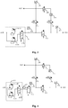
Fig. 1 is a schematic structural diagram of an apparatus for detecting air tightness according to an embodiment of the present application. -
Fig. 2 is a schematic structural diagram of an apparatus for detecting air tightness according to another embodiment of the present application. -
Fig. 3 is a schematic structural diagram of an apparatus for detecting air tightness according to yet another embodiment of the present application. -
Fig. 4 is a schematic structural diagram of an apparatus for detecting air tightness according to yet another embodiment of the present application. -
Fig. 5 is a schematic structural diagram of an apparatus for detecting air tightness according to yet another embodiment of the present application. - Features of various aspects of the present application and exemplary embodiments will be described in detail below. In the following detailed description, many specific details are proposed in order to provide a thorough understanding of this application.
- Embodiments of the present application provide an apparatus for detecting air tightness, which enables a low air pressure sensor to be embedded in an air tightness detector suitable for tests under high air pressure and to be effectively protected in a high air pressure environment, so that leakage tests under different inflation pressures can be implemented by one instrument. Compared with the prior art where the leakage tests under different inflation pressures are implemented by two instruments, the cost is significantly reduced, and it is more convenient to transfer and utilize one instrument than two instruments.
- As shown in
Fig. 1 , the apparatus for detecting air tightness has an air inlet end PI, an inflating end for an object to be tested PO1 and a standard part inflating end PO2. - The apparatus includes: a
pressure regulating component 101, where a first end of thepressure regulating component 101 is connected to the air inlet end PI; amain isolating valve 102, where a first end of themain isolating valve 102 is connected to a second end of thepressure regulating component 101, and a second end of themain isolating valve 102 is connected to the inflating end for the object to be tested PO1; a firstbypass isolating valve 103, where a first end of the firstbypass isolating valve 103 is connected to a gas pipeline that is between the second end of thepressure regulating component 101 and the first end of themain isolating valve 102, and a second end of the firstbypass isolating valve 103 is connected to the standard part inflating end PO2; a secondbypass isolating valve 104, where a first end of the secondbypass isolating valve 104 is connected to a gas pipeline that is between the second end of themain isolating valve 102 and the inflating end for the object to be tested PO1; a thirdbypass isolating valve 105, where a first end of the thirdbypass isolating valve 105 is connected to a gas pipeline that is between the second end of the firstbypass isolating valve 103 and the standard part inflating end PO2; a first highair pressure sensor 106, where a detecting end of the first highair pressure sensor 106 is connected to a gas pipeline that is between the second end of thepressure regulating component 101, the first end of themain isolating valve 102 and the first end of the firstbypass isolating valve 103; a second highair pressure sensor 107, where a detecting end of the second highair pressure sensor 107 is connected to a gas pipeline that is between the second end of themain isolating valve 102, the inflating end for the object to be tested PO1 and a second end of the secondbypass isolating valve 104; a lowair pressure sensor 108, where a detecting end of the lowair pressure sensor 108 is connected to a gas pipeline that is between the second end of the firstbypass isolating valve 103, the standard part inflating end PO2 and the first end of the thirdbypass isolating valve 105; and adifferential pressure sensor 109, where a first detecting end of thedifferential pressure sensor 109 is connected to the second end of the secondbypass isolating valve 104, and a second detecting end of thedifferential pressure sensor 109 is connected to a second end of the thirdbypass isolating valve 105. Themain isolating valve 102 may be a pneumatic control valve, and the firstbypass isolating valve 103, the secondbypass isolating valve 104 and the thirdbypass isolating valve 105 may be solenoid valves. - In order to help those skilled in the art to easily understand the working principles of the apparatus for detecting air tightness, the working processes of the apparatus will be described in detail below. An initial state of the apparatus will now be explained to facilitate subsequent description. The initial state of the apparatus refers to a state where the
main isolating valve 102, the firstbypass isolating valve 103, the secondbypass isolating valve 104 and the thirdbypass isolating valve 105 are all closed. - When it is required to perform a leakage test under high air pressure, the
main isolating valve 102, the firstbypass isolating valve 103, the secondbypass isolating valve 104 and the thirdbypass isolating valve 105 are closed. The pressure regulatingcomponent 101 is adjusted to make a value sensed by the first highair pressure sensor 106 level off at a target inflation pressure value. At this time, an output end of thepressure regulating component 101, the first highair pressure sensor 106, the closedmain isolating valve 102 and the closed firstbypass isolating valve 103 constitute an inflation pressure range-maintaining gas channel. Then, the main isolatingvalve 102 is opened to inflate an object to be tested. After the inflation of the object to be tested is completed, the main isolatingvalve 102 is closed, and air tightness detection is performed on the object to be tested using the second highair pressure sensor 107, where the air tightness detection method may be performed using a direct pressure method. After the test is completed, the apparatus is restored to the initial state. - When it is required to perform a leakage test under low air pressure, the main isolating
valve 102, the firstbypass isolating valve 103, the secondbypass isolating valve 104 and the thirdbypass isolating valve 105 are closed, and thepressure regulating component 101 is adjusted to make the value sensed by the first highair pressure sensor 106 in the above-mentioned inflation pressure range-maintaining gas channel level off at the target inflation pressure value. Since the first highair pressure sensor 106 is of a type that can withstand a relatively high air pressure, it will not be damaged by the high pressure outputted from thepressure regulating component 101 at the beginning of the test. However, the first highair pressure sensor 106 is not precise enough to meet the requirements for pressure precision of leakage test under low air pressure. Then, the firstbypass isolating valve 103 is opened and thepressure regulating component 101 is re-adjusted, so that a value sensed by the lowair pressure sensor 108 reaches the target inflation pressure value. At this time, it is determined whether the target inflation pressure value is reached according to the value sensed by the lowair pressure sensor 108 instead of the value sensed by the highair pressure sensor 106. As the air pressure has been preliminarily adjusted via the first highair pressure sensor 106 in the previous step, after the firstbypass isolating valve 103 is opened, pressure of the gas flowing to the lowair pressure sensor 108 will not cause damage to the low air pressure sensor. At the same time, since the thirdbypass isolating valve 105 is closed, thedifferential pressure sensor 109 will not be damaged by overly high pressure at one end of the differential pressure sensor. Moreover, after the pressure adjustment in this step, the output air pressure meets the precision requirements of the leakage test under low air pressure. Then, the main isolatingvalve 102, the secondbypass isolating valve 104 and the thirdbypass isolating valve 105 are opened to inflate the object to be tested. After the inflation is completed, an air pressure at the standard part inflating end PO2 and an air pressure at the inflating end for the object to be tested PO1 are compared with each other by thedifferential pressure sensor 109, and the leakage test under low air pressure is performed using a pressure differential method. After the test is completed, the apparatus is restored to the initial state. - It can be seen from the description of the above working process that, the apparatus enables that the low air pressure sensor and the high air pressure sensor in the prior art need not to be made into two separate air tightness detectors, and the low air pressure sensor would not be damaged during the leakage test under high pressure, that is to say, leakage tests under different inflation pressures can be implemented using one instrument. Compared with the prior art where the leakage tests under different inflation pressures are implemented by two instruments, the cost is significantly reduced, and it is more convenient to transfer and utilize one instrument than two instruments.
- Further, as shown in
Fig. 2 , the apparatus may further include a first divertingvalve 110. A first end of the first divertingvalve 110 is connected to a gas pipeline that is between the second end of the secondbypass isolating valve 104 and the first detecting end of thedifferential pressure sensor 109, and a second end of the first divertingvalve 110 is connected to a gas pipeline that is between the second detecting end of thedifferential pressure sensor 109 and the second end of the thirdbypass isolating valve 105. During the leakage test under high air pressure, the first divertingvalve 110 is always opened. When the main isolatingvalve 102 is opened to inflate the object to be tested, even if very small leakage occurs to the secondbypass isolating valve 104, since the first divertingvalve 110 is opened, the pressures at the both ends of thedifferential pressure sensor 109 remain the same, which ensures that thedifferential pressure sensor 109 will not be damaged. During the leakage test under low air pressure, the first divertingvalve 110 is also always opened. When the value sensed by the lowair pressure sensor 108 is adjusted to the target inflation pressure value, even if small leakage occurs to the thirdbypass isolating valve 105, since the first divertingvalve 110 is opened state, the pressures at the both ends of thedifferential pressure sensor 109 remain the same, which ensures that thedifferential pressure sensor 109 will not be damaged. The first divertingvalve 110 may be a solenoid valve. - In another optional embodiment, as shown in
Fig. 2 , the apparatus may further include a second divertingvalve 111. A first end of the second divertingvalve 111 is connected to the standard part inflating end PO2, and a second end of the second divertingvalve 111 is connected to a gas pipeline that is between the second end of the firstbypass isolating valve 103, the first end of the thirdbypass isolating valve 105 and the lowair pressure sensor 108. The second divertingvalve 111 may be a solenoid valve. - In addition, another optional example of the
pressure regulating component 101 will be described in detail, to facilitate specific implementation by those skilled in the art. Specifically, as shown inFig. 3 , thepressure regulating component 101 includes a firstpressure regulating valve 101A, a secondpressure regulating valve 101B and a first way-selecting valve 101C. Air pressure regulating ranges of the firstpressure regulating valve 101A and the secondpressure regulating valve 101B are different. For example, the air pressure regulating range of the firstpressure regulating valve 101A is from 100Kpa to 500Kpa, and the air pressure regulating range of the secondpressure regulating valve 101B is from 0 to 100pa. The adjustable range of the firstpressure regulating valve 101A is relatively large, but it is not precise enough in respect of a low air pressure situation. The adjustable range of the secondpressure regulating valve 101B is relatively small, but it is relatively precise in respect of a low air pressure situation. That is to say, coarse air-pressure adjustment can be realized by the firstpressure regulating valve 101A, and fine air-pressure adjustment can be realized by the secondpressure regulating valve 101B. An air outlet of the firstpressure regulating valve 101A is connected to the first end of the first way-selecting valve 101C, and an air outlet of the secondpressure regulating valve 101B is connected to a second end of the first way-selecting valve 101C; and a common end of the first way-selecting valve 101C is connected to the first end of the main isolatingvalve 102. In this situation, the first way-selecting valve 101C is connected to the firstpressure regulating valve 101A when the leakage test under high air pressure is performed, and the first way-selecting valve 101C is connected to the secondpressure regulating valve 101B when the leakage test under low air pressure is performed. The first way-selecting valve 101C may be a two-position three-way solenoid valve. - Furthermore, as shown in
Fig. 4 , the apparatus may further include a second way-selectingvalve 112 and amuffler 113. A first end of the second way-selectingvalve 112 is connected to themuffler 113, a second end of the second way-selectingvalve 112 is connected to the common end of the first way-selecting valve 101C, and a common end of the second way-selectingvalve 112 is connected to the first end of the main isolatingvalve 102. - In a preferable embodiment, an endurable pressure value of the first
bypass isolating valve 103 and/or the secondbypass isolating valve 104 is greater than the highest air pressure that thepressure regulating component 101 is able to output. Therefore, the firstbypass isolating valve 103 and the secondbypass isolating valve 104 are not liable to be damaged during the leakage test under high pressure and the leakage test under low pressure. - In addition,
Fig. 5 illustrates a combination of the foregoing embodiments, which will be described in detail below. - First, an initial state of the system is set. In the initial state, the first way-selecting valve 101C is connected to the second
pressure regulating valve 101B, the second way-selectingvalve 112 is connected to themuffler 113, the main isolatingvalve 102, the firstbypass isolating valve 103, the secondbypass isolating valve 104 and the thirdbypass isolating valve 105 are closed, and the first divertingvalve 110 and the second divertingvalve 111 are opened. - In the leakage test under high air pressure, following steps are taken.
- At step A1, the main isolating
valve 102, the firstbypass isolating valve 103, the secondbypass isolating valve 104 and the thirdbypass isolating valve 105 are closed, the first divertingvalve 110 and the second divertingvalve 111 are opened, the first way-selecting valve 101C is connected to the firstpressure regulating valve 101A, and the second way-selectingvalve 112 is connected to the common end of the first way-selecting valve 101C. - At step A2, the air pressure of the first
pressure regulating valve 101A is adjusted to make the value sensed by the first highair pressure sensor 106 level off at the target inflation pressure. At this time, the first highair pressure sensor 106, the output end of the firstpressure regulating valve 101A, the first way-selecting valve 101C, the second way-selectingvalve 112, the closed firstbypass isolating valve 103, the closed main isolatingvalve 102 and the gas channel between these components constitute the above-mentioned inflation pressure range-maintaining gas channel. The highest output air pressure of the firstpressure regulating valve 101A is Pmax1, and the endurable pressure value of the first highair pressure sensor 106 is greater than Pmax1. - At step A3, the main isolating
valve 102 is opened to inflate the object to be tested, the main isolatingvalve 102 is closed after the inflation is completed, and then air tightness detection is performed on the object to be tested using the second highair pressure sensor 107 through the direct pressure method. The endurable pressure value of the secondbypass isolating valve 104 is greater than Pmax1 and is closed, and the high pressure airflow will not flow into thedifferential pressure sensor 109. Even if a very small leakage occurs to the secondbypass isolating valve 104, since the first divertingvalve 110 is opened, the pressures at the both ends of thedifferential pressure sensor 109 are the same, thus thedifferential pressure sensor 109 will not be damaged. - At step A4, the system is restored to the initial state after the test is completed.
- In the leakage test under low air pressure, following steps are taken.
- At step B1, the main isolating
valve 102, the firstbypass isolating valve 103, the secondbypass isolating valve 104 and the thirdbypass isolating valve 105 are closed, the first divertingvalve 110 and the second divertingvalve 111 are opened, the first way-selecting valve 101C is connected to the secondpressure regulating valve 101B, and the second way-selectingvalve 112 is connected to the common end of the first way-selecting valve 101C. - At step B2, the second
pressure regulating valve 101B is adjusted to make the value presented by the first highair pressure sensor 106 in the above-mentioned inflation pressure range-maintaining gas channel be the target inflation pressure value. Since the first highair pressure sensor 106 is of type than can withstand high pressure, it will not be damaged by the overly high pressure outputted from the secondpressure regulating valve 101B at the beginning of the adjustment. However, the first highair pressure sensor 106 is not precise enough to meet the requirements for pressure precision of the leakage test under low air pressure. - At step B3, the first
bypass isolating valve 103 is opened, and the secondpressure regulating valve 101B is re-adjusted to make the value presented by the lowair pressure sensor 108 be the target inflation pressure value. At this time, the value presented by the first highair pressure sensor 106 is no longer taken into consideration. As the air pressure has been preliminarily adjusted at the previous step, after the first bypass isolating valve is opened, pressure of the gas flowing to the low air pressure sensor will not cause damage to the low air pressure sensor. Moreover, since the lowair pressure sensor 108 is of a high-precision type, after the pressure adjustment at this step, the output air pressure of the apparatus can meet the precision requirements of the leakage test under low air pressure. In addition, at this step, the thirdbypass isolating valve 105 is closed and the first divertingvalve 110 is opened, and therefore, the both ends of thedifferential pressure sensor 109 will not be damaged by overly high pressure at one end. - At step B4, the main isolating
valve 102, the secondbypass isolating valve 104 and the thirdbypass isolating valve 105 are opened, the first divertingvalve 110 is kept not closed for a while, so as to avoid overly large pressure difference between the both ends of thedifferential pressure sensor 109 which otherwise would damage thedifferential pressure sensor 109, then the object to be tested is inflated, after the inflation is completed, the first divertingvalve 110 is closed, and then the leakage test under low air pressure is performed using a pressure differential method through thedifferential pressure sensor 109. - At step B5, the apparatus is restored to the initial state after the test is completed.
- It should be clear that the respective embodiments in the specification are described in a progressive way, and the same or similar parts of each embodiment can be referred to each other. The description of each embodiment focuses on the differences with other embodiments. In the embodiments of the apparatuses, the corresponding parts can refer to the description sections of the embodiments of the methods. The embodiments of present application are not limited to the specific structures described above and shown in the drawings. Those skilled in the art can make various changes, modifications and additions after understanding the gist of the present application. Moreover, for the sake of brevity, the detailed description of known processes and techniques is omitted.
- The embodiments of the present application can be implemented in other specific forms without departing from its gist or essential characteristics. For example, an algorithm described in a specific embodiment can be modified without the system architecture departing from the basic gist of the embodiments of the present application. Therefore, all aspects of the current embodiments are considered to be exemplary rather than limiting. The scope of the embodiments of the present application is defined by the appended claims rather than the above description. All modifications falling within the meaning of the claims and equivalents are included in the scope of the embodiments of the present application.
- Those skilled in the art should understand that the above-mentioned embodiments are all exemplary instead of restrictive. Different technical features appearing in different embodiments can be combined to obtain beneficial effects. Those skilled in the art should be able to understand and implement other modified embodiments of the disclosed embodiments on the basis of studying the drawings, the description, and the claims. In the claims, the term "including" does not exclude other devices or steps; the indefinite article "a" or "an" does not exclude a plurality; the terms "first" and "second" are used to indicate names and not to indicate any particular order. Any reference signs in the claims should not be construed as limiting the scope of protection. The functions of several parts appearing in the claims can be realized by a single hardware or software module. The presence of certain technical features in different dependent claims does not mean that these technical features cannot be combined to obtain beneficial effects.
Claims (10)
- An apparatus for detecting air tightness, having an air inlet end, an inflating end for an object to be tested and a standard part inflating end, the apparatus comprising:a pressure regulating component, wherein a first end of the pressure regulating component is connected to the air inlet end;a main isolating valve, wherein a first end of the main isolating valve is connected to a second end of the pressure regulating component, and a second end of the main isolating valve is connected to the inflating end for the object to be tested;a first bypass isolating valve, wherein a first end of the first bypass isolating valve is connected to a gas pipeline that is between the second end of the pressure regulating component and the first end of the main isolating valve, and a second end of the first bypass isolating valve is connected to the standard part inflating end;a second bypass isolating valve, wherein a first end of the second bypass isolating valve is connected to a gas pipeline that is between the second end of the main isolating valve and the inflating end for the object to be tested;a third bypass isolating valve, wherein a first end of the third bypass isolating valve is connected to a gas pipeline that is between the second end of the first bypass isolating valve and the standard part inflating end;a first high air pressure sensor, wherein a detecting end of the first high air pressure sensor is connected to a gas pipeline that is between the second end of the pressure regulating component, the first end of the main isolating valve and the first end of the first bypass isolating valve;a second high air pressure sensor, wherein a detecting end of the second high air pressure sensor is connected to a gas pipeline that is between the second end of the main isolating valve, the inflating end for the object to be tested and a second end of the second bypass isolating valve;a low air pressure sensor, wherein a detecting end of the low air pressure sensor is connected to a gas pipeline that is between the second end of the first bypass isolating valve, the standard part inflating end and the first end of the third bypass isolating valve; anda differential pressure sensor, wherein a first detecting end of the differential pressure sensor is connected to the second end of the second bypass isolating valve, and a second detecting end of the differential pressure sensor is connected to a second end of the third bypass isolating valve.
- The apparatus according to claim 1, further comprising a first diverting valve, wherein a first end of the first diverting valve is connected to a gas pipeline that is between the second end of the second bypass isolating valve and the first detecting end of the differential pressure sensor, and a second end of the first diverting valve is connected to a gas pipeline that is between the second detecting end of the differential pressure sensor and the second end of the third bypass isolating valve.
- The apparatus according to claim 1, further comprising a second diverting valve, a first end of the second diverting valve is connected to the standard part inflating end, and a second end of the second diverting valve is connected to a gas pipeline that is between the second end of the first bypass isolating valve, the first end of the third bypass isolating valve and the low air pressure sensor.
- The apparatus according to claim 1, wherein the pressure regulating component comprises a first pressure regulating valve, a second pressure regulating valve and a first way-selecting valve;
air pressure regulating ranges of the first pressure regulating valve and the second pressure regulating valve are different;
air inlets of the first pressure regulating valve and the second pressure regulating valve are both connected to the air inlet end;
an air outlet of the first pressure regulating valve is connected to a first end of the first way-selecting valve, and an air outlet of the second pressure regulating valve is connected to a second end of the first way-selecting valve; and
a common end of the first way-selecting valve is connected to the first end of the main isolating valve. - The apparatus according to claim 4, wherein,
the air pressure regulating range of the first pressure regulating valve is from 100Kpa to 500Kpa; and
the air pressure regulating range of the second pressure regulating valve is from 0 to 100pa. - The apparatus according to claim 4, wherein the first way-selecting valve is a two-position three-way solenoid valve.
- The apparatus according to claim 6, further comprising a second way-selecting valve and a muffler, wherein
a first end of the second way-selecting valve is connected to the muffler, a second end of the second way-selecting valve is connected to the common end of the first way-selecting valve, and a common end of the second way-selecting valve is connected to the first end of the main isolating valve. - The apparatus according to claim 1, wherein the main isolating valve is a pneumatic control valve.
- The apparatus according to claim 1, wherein the first bypass isolating valve, the second bypass isolating valve and the third bypass isolating valve are all solenoid valves.
- The apparatus according to claim 1, wherein an endurable pressure value of the first bypass isolating valve and/or the second bypass isolating valve is greater than a highest air pressure that the pressure regulating component is able to output.
Applications Claiming Priority (2)
| Application Number | Priority Date | Filing Date | Title |
|---|---|---|---|
| CN201921291912.3U CN210741775U (en) | 2019-08-09 | 2019-08-09 | Air tightness detection device |
| PCT/CN2020/101675 WO2021027462A1 (en) | 2019-08-09 | 2020-07-13 | Air tightness detection device |
Publications (3)
| Publication Number | Publication Date |
|---|---|
| EP3812731A1 true EP3812731A1 (en) | 2021-04-28 |
| EP3812731A4 EP3812731A4 (en) | 2021-11-03 |
| EP3812731B1 EP3812731B1 (en) | 2022-07-06 |
Family
ID=71008363
Family Applications (1)
| Application Number | Title | Priority Date | Filing Date |
|---|---|---|---|
| EP20824418.6A Active EP3812731B1 (en) | 2019-08-09 | 2020-07-13 | Air tightness detection device |
Country Status (4)
| Country | Link |
|---|---|
| US (1) | US11598690B2 (en) |
| EP (1) | EP3812731B1 (en) |
| CN (1) | CN210741775U (en) |
| WO (1) | WO2021027462A1 (en) |
Cited By (1)
| Publication number | Priority date | Publication date | Assignee | Title |
|---|---|---|---|---|
| EP3812731A4 (en) * | 2019-08-09 | 2021-11-03 | Contemporary Amperex Technology Co., Limited | AIR LEAKAGE DETECTION DEVICE |
Families Citing this family (14)
| Publication number | Priority date | Publication date | Assignee | Title |
|---|---|---|---|---|
| CN113776743A (en) * | 2021-09-16 | 2021-12-10 | 浙江杰奈尔新材料有限公司 | Air tightness detector and air tightness measuring method thereof |
| CN114018504A (en) * | 2021-11-03 | 2022-02-08 | 厦门理工学院 | Air tightness testing device and method |
| CN114414171B (en) * | 2022-01-24 | 2023-07-14 | 中山市铧禧电子科技有限公司 | Water purifier detection method |
| CN114526877A (en) * | 2022-02-22 | 2022-05-24 | 三门核电有限公司 | Check valve low-pressure-difference sealing performance detection system and detection method |
| CN114993572B (en) * | 2022-06-20 | 2024-11-08 | 苏州浪潮智能科技有限公司 | Air tightness detection device, system and detection method |
| CN114791341B (en) * | 2022-06-23 | 2022-09-13 | 北京迈世高科电子技术有限公司 | Air tightness detection method and detector |
| CN218787890U (en) * | 2022-10-26 | 2023-04-04 | 上海韦航装备科技有限公司 | Sealing detection equipment |
| CN115560926B (en) * | 2022-11-30 | 2023-06-06 | 四川欧乐智能技术有限公司 | Mobile phone tightness detection method and device |
| CN116358808B (en) * | 2023-05-31 | 2023-10-27 | 宁德时代新能源科技股份有限公司 | Air tightness testing method and air tightness testing device |
| CN116717721A (en) * | 2023-06-15 | 2023-09-08 | 深圳市凌龙科技有限公司 | Air supply system and air supply method |
| EP4509810A4 (en) * | 2023-06-21 | 2025-02-19 | Contemporary Amperex Technology (Hong Kong) Limited | SEALING PERFORMANCE TEST CABINET FOR BATTERY PACK |
| CN117212706A (en) * | 2023-09-06 | 2023-12-12 | 瑞莱谱(杭州)医疗科技有限公司 | An adjustable pressure control device for gas pressure testing |
| CN118532614A (en) * | 2024-04-28 | 2024-08-23 | 上海空间推进研究所 | Automatic inflation and deflation device and implementation method during air tightness test |
| CN119779597B (en) * | 2024-12-31 | 2026-04-21 | 深圳市希立仪器设备有限公司 | A method for testing the airtightness of tents applicable to multiple scenarios |
Family Cites Families (21)
| Publication number | Priority date | Publication date | Assignee | Title |
|---|---|---|---|---|
| EP0063113A1 (en) * | 1980-10-24 | 1982-10-27 | Nolek System Ab | Method and device for tightness testing of a test object having at least two separate chambers |
| US4441357A (en) * | 1982-03-04 | 1984-04-10 | Meadox Instruments, Inc. | Pressure monitoring and leak detection method and apparatus |
| US4993256A (en) * | 1988-04-20 | 1991-02-19 | Kabushiki Kaisha Fukuda | Leakage test method and apparatus |
| US5059348A (en) * | 1990-12-31 | 1991-10-22 | The United States Of America As Represented By The Secretary Of The Army | Method for measuring the efficiency of gas mask filters |
| US5412978A (en) * | 1993-06-22 | 1995-05-09 | Phase 1 Instruments, Inc. | Leak detection system |
| JP3766997B2 (en) * | 1995-12-18 | 2006-04-19 | 日本ゼオン株式会社 | Medical expansion / contraction drive |
| JP3666209B2 (en) * | 1997-10-21 | 2005-06-29 | 株式会社デンソー | Leak inspection method and inspection apparatus |
| US6435010B1 (en) * | 2001-04-23 | 2002-08-20 | John Leslie Johnson | Leak detection system |
| CN2676170Y (en) * | 2003-05-09 | 2005-02-02 | 浙江三花股份有限公司 | Integrated test system for one-way valve |
| CN201917443U (en) * | 2010-12-21 | 2011-08-03 | 浙江亚太机电股份有限公司 | High-pressure gas precision detecting pipeline system used for detecting product |
| ES2638793T3 (en) * | 2012-06-05 | 2017-10-24 | Sciemetric Instruments Inc. | Methods and systems for leak testing |
| DE102012013521A1 (en) * | 2012-07-06 | 2014-01-09 | Knorr-Bremse Systeme für Schienenfahrzeuge GmbH | Method for detecting leaks in a brake pressure leading brake pressure line of a rail vehicle |
| CN104236820B (en) * | 2014-09-29 | 2017-11-17 | 天津博益气动股份有限公司 | A kind of airtight leak detector of differential pressure type and detection method for big volume measured object |
| CN104406750B (en) * | 2014-12-16 | 2017-06-13 | 深圳市汉斯顿净水设备有限公司 | The device for detecting sealability and detection method of a kind of water purification machine |
| CN106768704B (en) * | 2016-12-22 | 2023-07-21 | 青岛杰瑞工控技术有限公司 | Mobile air tightness detection device and method for overhauling train of motor train unit |
| CN206440441U (en) * | 2017-02-14 | 2017-08-25 | 沈阳金科精密仪器设备有限公司 | A kind of differential pressure type air leakage tester |
| CN206710036U (en) * | 2017-03-16 | 2017-12-05 | 中国商用飞机有限责任公司 | For the equipment for the air-tightness for detecting aircraft air condition pipeline |
| CN107228745B (en) * | 2017-07-14 | 2023-05-09 | 深圳市高晟智能装备有限公司 | Ball valve air tightness testing method and testing system |
| CN107576458A (en) | 2017-09-26 | 2018-01-12 | 安徽安凯汽车股份有限公司 | A kind of brake line of automobile air-tightness automatic detection device and its detection method |
| CN208672248U (en) | 2018-06-29 | 2019-03-29 | 杭州固恒能源科技有限公司 | A kind of air charging system and differential pressure air-leakage detector from high-pressure air source to workpiece |
| CN210741775U (en) * | 2019-08-09 | 2020-06-12 | 宁德时代新能源科技股份有限公司 | Air tightness detection device |
-
2019
- 2019-08-09 CN CN201921291912.3U patent/CN210741775U/en active Active
-
2020
- 2020-07-13 EP EP20824418.6A patent/EP3812731B1/en active Active
- 2020-07-13 WO PCT/CN2020/101675 patent/WO2021027462A1/en not_active Ceased
- 2020-12-28 US US17/134,567 patent/US11598690B2/en active Active
Cited By (2)
| Publication number | Priority date | Publication date | Assignee | Title |
|---|---|---|---|---|
| EP3812731A4 (en) * | 2019-08-09 | 2021-11-03 | Contemporary Amperex Technology Co., Limited | AIR LEAKAGE DETECTION DEVICE |
| US11598690B2 (en) | 2019-08-09 | 2023-03-07 | Contemporary Amperex Technology Co., Limited | Apparatus for detecting air tightness |
Also Published As
| Publication number | Publication date |
|---|---|
| EP3812731A4 (en) | 2021-11-03 |
| US20210116324A1 (en) | 2021-04-22 |
| US11598690B2 (en) | 2023-03-07 |
| WO2021027462A1 (en) | 2021-02-18 |
| CN210741775U (en) | 2020-06-12 |
| EP3812731B1 (en) | 2022-07-06 |
Similar Documents
| Publication | Publication Date | Title |
|---|---|---|
| EP3812731B1 (en) | Air tightness detection device | |
| CN104266803A (en) | Airtight detecting system and method | |
| CN107543661B (en) | The adjustable vacuum leak hunting automated system of sensitivity | |
| CN201532292U (en) | Pneumatic circuit of multifunctional gas-tightness detector | |
| JP2001516047A (en) | Pipe leak detector | |
| KR20090025823A (en) | Vacuum gauge calibration / testing apparatus and method thereof | |
| CN110987324A (en) | A kind of fuel cell air tightness test equipment and test method | |
| JP2000186897A (en) | Automotive heat exchanger leak detection method and apparatus | |
| JP5806462B2 (en) | Leak inspection apparatus and method | |
| CN104215290A (en) | Differential-pressure type volume detection device and detection method | |
| CN109186883B (en) | Air tightness detection system and method for square lithium ion battery | |
| JP3201667B2 (en) | Check valve test apparatus and check valve test method | |
| CN104215408A (en) | Valve air tightness detection system | |
| CN104236820A (en) | Differential pressure type airtightness detecting instrument and device for detecting large-sized objects | |
| CN203275043U (en) | Air-impermeability detection system of valve | |
| CN107257917A (en) | Component and method for the Leakage Test of container | |
| CN217424683U (en) | Differential pressure method gas tightness detection valve | |
| TW202300879A (en) | Leak detection device and method for venting leak detection device | |
| CN115336421B (en) | A helium mass spectrometry leak detection device for single-component thrusters | |
| CN217930750U (en) | Soft bag detection device | |
| CN210036906U (en) | Negative pressure source device and gas meter verification gas circuit system | |
| TWI490673B (en) | Pressure control system and method | |
| JP2018004429A (en) | Leakage inspection device and leakage inspection method | |
| CN117288405A (en) | Soft bag detection method | |
| CN116067589A (en) | Vacuum based leak detection |
Legal Events
| Date | Code | Title | Description |
|---|---|---|---|
| STAA | Information on the status of an ep patent application or granted ep patent |
Free format text: STATUS: UNKNOWN |
|
| STAA | Information on the status of an ep patent application or granted ep patent |
Free format text: STATUS: THE INTERNATIONAL PUBLICATION HAS BEEN MADE |
|
| PUAI | Public reference made under article 153(3) epc to a published international application that has entered the european phase |
Free format text: ORIGINAL CODE: 0009012 |
|
| STAA | Information on the status of an ep patent application or granted ep patent |
Free format text: STATUS: REQUEST FOR EXAMINATION WAS MADE |
|
| 17P | Request for examination filed |
Effective date: 20201223 |
|
| AK | Designated contracting states |
Kind code of ref document: A1 Designated state(s): AL AT BE BG CH CY CZ DE DK EE ES FI FR GB GR HR HU IE IS IT LI LT LU LV MC MK MT NL NO PL PT RO RS SE SI SK SM TR |
|
| AX | Request for extension of the european patent |
Extension state: BA ME |
|
| A4 | Supplementary search report drawn up and despatched |
Effective date: 20211005 |
|
| RIC1 | Information provided on ipc code assigned before grant |
Ipc: G01M 3/32 20060101ALI20210929BHEP Ipc: G01M 3/26 20060101AFI20210929BHEP |
|
| GRAP | Despatch of communication of intention to grant a patent |
Free format text: ORIGINAL CODE: EPIDOSNIGR1 |
|
| STAA | Information on the status of an ep patent application or granted ep patent |
Free format text: STATUS: GRANT OF PATENT IS INTENDED |
|
| INTG | Intention to grant announced |
Effective date: 20220208 |
|
| GRAS | Grant fee paid |
Free format text: ORIGINAL CODE: EPIDOSNIGR3 |
|
| GRAA | (expected) grant |
Free format text: ORIGINAL CODE: 0009210 |
|
| STAA | Information on the status of an ep patent application or granted ep patent |
Free format text: STATUS: THE PATENT HAS BEEN GRANTED |
|
| AK | Designated contracting states |
Kind code of ref document: B1 Designated state(s): AL AT BE BG CH CY CZ DE DK EE ES FI FR GB GR HR HU IE IS IT LI LT LU LV MC MK MT NL NO PL PT RO RS SE SI SK SM TR |
|
| DAV | Request for validation of the european patent (deleted) | ||
| DAX | Request for extension of the european patent (deleted) | ||
| REG | Reference to a national code |
Ref country code: AT Ref legal event code: REF Ref document number: 1503179 Country of ref document: AT Kind code of ref document: T Effective date: 20220715 Ref country code: CH Ref legal event code: EP |
|
| REG | Reference to a national code |
Ref country code: DE Ref legal event code: R096 Ref document number: 602020003925 Country of ref document: DE |
|
| REG | Reference to a national code |
Ref country code: IE Ref legal event code: FG4D |
|
| REG | Reference to a national code |
Ref country code: LT Ref legal event code: MG9D |
|
| REG | Reference to a national code |
Ref country code: NL Ref legal event code: MP Effective date: 20220706 |
|
| PG25 | Lapsed in a contracting state [announced via postgrant information from national office to epo] |
Ref country code: SE Free format text: LAPSE BECAUSE OF FAILURE TO SUBMIT A TRANSLATION OF THE DESCRIPTION OR TO PAY THE FEE WITHIN THE PRESCRIBED TIME-LIMIT Effective date: 20220706 Ref country code: RS Free format text: LAPSE BECAUSE OF FAILURE TO SUBMIT A TRANSLATION OF THE DESCRIPTION OR TO PAY THE FEE WITHIN THE PRESCRIBED TIME-LIMIT Effective date: 20220706 Ref country code: PT Free format text: LAPSE BECAUSE OF FAILURE TO SUBMIT A TRANSLATION OF THE DESCRIPTION OR TO PAY THE FEE WITHIN THE PRESCRIBED TIME-LIMIT Effective date: 20221107 Ref country code: NO Free format text: LAPSE BECAUSE OF FAILURE TO SUBMIT A TRANSLATION OF THE DESCRIPTION OR TO PAY THE FEE WITHIN THE PRESCRIBED TIME-LIMIT Effective date: 20221006 Ref country code: NL Free format text: LAPSE BECAUSE OF FAILURE TO SUBMIT A TRANSLATION OF THE DESCRIPTION OR TO PAY THE FEE WITHIN THE PRESCRIBED TIME-LIMIT Effective date: 20220706 Ref country code: LV Free format text: LAPSE BECAUSE OF FAILURE TO SUBMIT A TRANSLATION OF THE DESCRIPTION OR TO PAY THE FEE WITHIN THE PRESCRIBED TIME-LIMIT Effective date: 20220706 Ref country code: LT Free format text: LAPSE BECAUSE OF FAILURE TO SUBMIT A TRANSLATION OF THE DESCRIPTION OR TO PAY THE FEE WITHIN THE PRESCRIBED TIME-LIMIT Effective date: 20220706 Ref country code: FI Free format text: LAPSE BECAUSE OF FAILURE TO SUBMIT A TRANSLATION OF THE DESCRIPTION OR TO PAY THE FEE WITHIN THE PRESCRIBED TIME-LIMIT Effective date: 20220706 Ref country code: ES Free format text: LAPSE BECAUSE OF FAILURE TO SUBMIT A TRANSLATION OF THE DESCRIPTION OR TO PAY THE FEE WITHIN THE PRESCRIBED TIME-LIMIT Effective date: 20220706 |
|
| REG | Reference to a national code |
Ref country code: AT Ref legal event code: MK05 Ref document number: 1503179 Country of ref document: AT Kind code of ref document: T Effective date: 20220706 |
|
| PG25 | Lapsed in a contracting state [announced via postgrant information from national office to epo] |
Ref country code: PL Free format text: LAPSE BECAUSE OF FAILURE TO SUBMIT A TRANSLATION OF THE DESCRIPTION OR TO PAY THE FEE WITHIN THE PRESCRIBED TIME-LIMIT Effective date: 20220706 Ref country code: IS Free format text: LAPSE BECAUSE OF FAILURE TO SUBMIT A TRANSLATION OF THE DESCRIPTION OR TO PAY THE FEE WITHIN THE PRESCRIBED TIME-LIMIT Effective date: 20221106 Ref country code: HR Free format text: LAPSE BECAUSE OF FAILURE TO SUBMIT A TRANSLATION OF THE DESCRIPTION OR TO PAY THE FEE WITHIN THE PRESCRIBED TIME-LIMIT Effective date: 20220706 Ref country code: GR Free format text: LAPSE BECAUSE OF FAILURE TO SUBMIT A TRANSLATION OF THE DESCRIPTION OR TO PAY THE FEE WITHIN THE PRESCRIBED TIME-LIMIT Effective date: 20221007 |
|
| REG | Reference to a national code |
Ref country code: BE Ref legal event code: MM Effective date: 20220731 |
|
| REG | Reference to a national code |
Ref country code: DE Ref legal event code: R097 Ref document number: 602020003925 Country of ref document: DE |
|
| PG25 | Lapsed in a contracting state [announced via postgrant information from national office to epo] |
Ref country code: SM Free format text: LAPSE BECAUSE OF FAILURE TO SUBMIT A TRANSLATION OF THE DESCRIPTION OR TO PAY THE FEE WITHIN THE PRESCRIBED TIME-LIMIT Effective date: 20220706 Ref country code: RO Free format text: LAPSE BECAUSE OF FAILURE TO SUBMIT A TRANSLATION OF THE DESCRIPTION OR TO PAY THE FEE WITHIN THE PRESCRIBED TIME-LIMIT Effective date: 20220706 Ref country code: MC Free format text: LAPSE BECAUSE OF FAILURE TO SUBMIT A TRANSLATION OF THE DESCRIPTION OR TO PAY THE FEE WITHIN THE PRESCRIBED TIME-LIMIT Effective date: 20220706 Ref country code: LU Free format text: LAPSE BECAUSE OF NON-PAYMENT OF DUE FEES Effective date: 20220713 Ref country code: DK Free format text: LAPSE BECAUSE OF FAILURE TO SUBMIT A TRANSLATION OF THE DESCRIPTION OR TO PAY THE FEE WITHIN THE PRESCRIBED TIME-LIMIT Effective date: 20220706 Ref country code: CZ Free format text: LAPSE BECAUSE OF FAILURE TO SUBMIT A TRANSLATION OF THE DESCRIPTION OR TO PAY THE FEE WITHIN THE PRESCRIBED TIME-LIMIT Effective date: 20220706 Ref country code: AT Free format text: LAPSE BECAUSE OF FAILURE TO SUBMIT A TRANSLATION OF THE DESCRIPTION OR TO PAY THE FEE WITHIN THE PRESCRIBED TIME-LIMIT Effective date: 20220706 |
|
| PLBE | No opposition filed within time limit |
Free format text: ORIGINAL CODE: 0009261 |
|
| STAA | Information on the status of an ep patent application or granted ep patent |
Free format text: STATUS: NO OPPOSITION FILED WITHIN TIME LIMIT |
|
| PG25 | Lapsed in a contracting state [announced via postgrant information from national office to epo] |
Ref country code: SK Free format text: LAPSE BECAUSE OF FAILURE TO SUBMIT A TRANSLATION OF THE DESCRIPTION OR TO PAY THE FEE WITHIN THE PRESCRIBED TIME-LIMIT Effective date: 20220706 Ref country code: EE Free format text: LAPSE BECAUSE OF FAILURE TO SUBMIT A TRANSLATION OF THE DESCRIPTION OR TO PAY THE FEE WITHIN THE PRESCRIBED TIME-LIMIT Effective date: 20220706 Ref country code: BE Free format text: LAPSE BECAUSE OF NON-PAYMENT OF DUE FEES Effective date: 20220731 |
|
| 26N | No opposition filed |
Effective date: 20230411 |
|
| P01 | Opt-out of the competence of the unified patent court (upc) registered |
Effective date: 20230516 |
|
| PG25 | Lapsed in a contracting state [announced via postgrant information from national office to epo] |
Ref country code: AL Free format text: LAPSE BECAUSE OF FAILURE TO SUBMIT A TRANSLATION OF THE DESCRIPTION OR TO PAY THE FEE WITHIN THE PRESCRIBED TIME-LIMIT Effective date: 20220706 |
|
| PG25 | Lapsed in a contracting state [announced via postgrant information from national office to epo] |
Ref country code: IE Free format text: LAPSE BECAUSE OF NON-PAYMENT OF DUE FEES Effective date: 20220713 |
|
| PG25 | Lapsed in a contracting state [announced via postgrant information from national office to epo] |
Ref country code: SI Free format text: LAPSE BECAUSE OF FAILURE TO SUBMIT A TRANSLATION OF THE DESCRIPTION OR TO PAY THE FEE WITHIN THE PRESCRIBED TIME-LIMIT Effective date: 20220706 |
|
| PG25 | Lapsed in a contracting state [announced via postgrant information from national office to epo] |
Ref country code: IT Free format text: LAPSE BECAUSE OF FAILURE TO SUBMIT A TRANSLATION OF THE DESCRIPTION OR TO PAY THE FEE WITHIN THE PRESCRIBED TIME-LIMIT Effective date: 20220706 |
|
| REG | Reference to a national code |
Ref country code: CH Ref legal event code: PL |
|
| PG25 | Lapsed in a contracting state [announced via postgrant information from national office to epo] |
Ref country code: MK Free format text: LAPSE BECAUSE OF FAILURE TO SUBMIT A TRANSLATION OF THE DESCRIPTION OR TO PAY THE FEE WITHIN THE PRESCRIBED TIME-LIMIT Effective date: 20220706 Ref country code: CY Free format text: LAPSE BECAUSE OF FAILURE TO SUBMIT A TRANSLATION OF THE DESCRIPTION OR TO PAY THE FEE WITHIN THE PRESCRIBED TIME-LIMIT Effective date: 20220706 Ref country code: CH Free format text: LAPSE BECAUSE OF NON-PAYMENT OF DUE FEES Effective date: 20230731 |
|
| PG25 | Lapsed in a contracting state [announced via postgrant information from national office to epo] |
Ref country code: HU Free format text: LAPSE BECAUSE OF FAILURE TO SUBMIT A TRANSLATION OF THE DESCRIPTION OR TO PAY THE FEE WITHIN THE PRESCRIBED TIME-LIMIT; INVALID AB INITIO Effective date: 20200713 |
|
| PG25 | Lapsed in a contracting state [announced via postgrant information from national office to epo] |
Ref country code: TR Free format text: LAPSE BECAUSE OF FAILURE TO SUBMIT A TRANSLATION OF THE DESCRIPTION OR TO PAY THE FEE WITHIN THE PRESCRIBED TIME-LIMIT Effective date: 20220706 |
|
| PG25 | Lapsed in a contracting state [announced via postgrant information from national office to epo] |
Ref country code: BG Free format text: LAPSE BECAUSE OF FAILURE TO SUBMIT A TRANSLATION OF THE DESCRIPTION OR TO PAY THE FEE WITHIN THE PRESCRIBED TIME-LIMIT Effective date: 20220706 |
|
| REG | Reference to a national code |
Ref country code: DE Ref legal event code: R081 Ref document number: 602020003925 Country of ref document: DE Owner name: CONTEMPORARY AMPEREX TECHNOLOGY (HONG KONG) LI, HK Free format text: FORMER OWNER: CONTEMPORARY AMPEREX TECHNOLOGY CO., LIMITED, NINGDE CITY, FUJIAN, CN |
|
| REG | Reference to a national code |
Ref country code: GB Ref legal event code: 732E Free format text: REGISTERED BETWEEN 20240829 AND 20240904 |
|
| PG25 | Lapsed in a contracting state [announced via postgrant information from national office to epo] |
Ref country code: MT Free format text: LAPSE BECAUSE OF FAILURE TO SUBMIT A TRANSLATION OF THE DESCRIPTION OR TO PAY THE FEE WITHIN THE PRESCRIBED TIME-LIMIT Effective date: 20220706 |
|
| PGFP | Annual fee paid to national office [announced via postgrant information from national office to epo] |
Ref country code: GB Payment date: 20250522 Year of fee payment: 6 |
|
| PGFP | Annual fee paid to national office [announced via postgrant information from national office to epo] |
Ref country code: FR Payment date: 20250508 Year of fee payment: 6 |
|
| PGFP | Annual fee paid to national office [announced via postgrant information from national office to epo] |
Ref country code: DE Payment date: 20250521 Year of fee payment: 6 |
|
| PG25 | Lapsed in a contracting state [announced via postgrant information from national office to epo] |
Ref country code: CH Free format text: THE PATENT HAS BEEN ANNULLED BY A DECISION OF A NATIONAL AUTHORITY Effective date: 20230731 |