EP3812651A1 - Vehicle lighting fixture - Google Patents
Vehicle lighting fixture Download PDFInfo
- Publication number
- EP3812651A1 EP3812651A1 EP19821997.4A EP19821997A EP3812651A1 EP 3812651 A1 EP3812651 A1 EP 3812651A1 EP 19821997 A EP19821997 A EP 19821997A EP 3812651 A1 EP3812651 A1 EP 3812651A1
- Authority
- EP
- European Patent Office
- Prior art keywords
- light
- low
- separator body
- projection lens
- front surface
- Prior art date
- Legal status (The legal status is an assumption and is not a legal conclusion. Google has not performed a legal analysis and makes no representation as to the accuracy of the status listed.)
- Granted
Links
Images













Classifications
-
- F—MECHANICAL ENGINEERING; LIGHTING; HEATING; WEAPONS; BLASTING
- F21—LIGHTING
- F21S—NON-PORTABLE LIGHTING DEVICES; SYSTEMS THEREOF; VEHICLE LIGHTING DEVICES SPECIALLY ADAPTED FOR VEHICLE EXTERIORS
- F21S41/00—Illuminating devices specially adapted for vehicle exteriors, e.g. headlamps
- F21S41/60—Illuminating devices specially adapted for vehicle exteriors, e.g. headlamps characterised by a variable light distribution
-
- F—MECHANICAL ENGINEERING; LIGHTING; HEATING; WEAPONS; BLASTING
- F21—LIGHTING
- F21S—NON-PORTABLE LIGHTING DEVICES; SYSTEMS THEREOF; VEHICLE LIGHTING DEVICES SPECIALLY ADAPTED FOR VEHICLE EXTERIORS
- F21S41/00—Illuminating devices specially adapted for vehicle exteriors, e.g. headlamps
- F21S41/20—Illuminating devices specially adapted for vehicle exteriors, e.g. headlamps characterised by refractors, transparent cover plates, light guides or filters
- F21S41/25—Projection lenses
- F21S41/255—Lenses with a front view of circular or truncated circular outline
-
- F—MECHANICAL ENGINEERING; LIGHTING; HEATING; WEAPONS; BLASTING
- F21—LIGHTING
- F21S—NON-PORTABLE LIGHTING DEVICES; SYSTEMS THEREOF; VEHICLE LIGHTING DEVICES SPECIALLY ADAPTED FOR VEHICLE EXTERIORS
- F21S41/00—Illuminating devices specially adapted for vehicle exteriors, e.g. headlamps
- F21S41/10—Illuminating devices specially adapted for vehicle exteriors, e.g. headlamps characterised by the light source
- F21S41/14—Illuminating devices specially adapted for vehicle exteriors, e.g. headlamps characterised by the light source characterised by the type of light source
- F21S41/141—Light emitting diodes [LED]
- F21S41/143—Light emitting diodes [LED] the main emission direction of the LED being parallel to the optical axis of the illuminating device
-
- F—MECHANICAL ENGINEERING; LIGHTING; HEATING; WEAPONS; BLASTING
- F21—LIGHTING
- F21S—NON-PORTABLE LIGHTING DEVICES; SYSTEMS THEREOF; VEHICLE LIGHTING DEVICES SPECIALLY ADAPTED FOR VEHICLE EXTERIORS
- F21S41/00—Illuminating devices specially adapted for vehicle exteriors, e.g. headlamps
- F21S41/10—Illuminating devices specially adapted for vehicle exteriors, e.g. headlamps characterised by the light source
- F21S41/14—Illuminating devices specially adapted for vehicle exteriors, e.g. headlamps characterised by the light source characterised by the type of light source
- F21S41/141—Light emitting diodes [LED]
- F21S41/151—Light emitting diodes [LED] arranged in one or more lines
-
- F—MECHANICAL ENGINEERING; LIGHTING; HEATING; WEAPONS; BLASTING
- F21—LIGHTING
- F21S—NON-PORTABLE LIGHTING DEVICES; SYSTEMS THEREOF; VEHICLE LIGHTING DEVICES SPECIALLY ADAPTED FOR VEHICLE EXTERIORS
- F21S41/00—Illuminating devices specially adapted for vehicle exteriors, e.g. headlamps
- F21S41/10—Illuminating devices specially adapted for vehicle exteriors, e.g. headlamps characterised by the light source
- F21S41/19—Attachment of light sources or lamp holders
-
- F—MECHANICAL ENGINEERING; LIGHTING; HEATING; WEAPONS; BLASTING
- F21—LIGHTING
- F21S—NON-PORTABLE LIGHTING DEVICES; SYSTEMS THEREOF; VEHICLE LIGHTING DEVICES SPECIALLY ADAPTED FOR VEHICLE EXTERIORS
- F21S41/00—Illuminating devices specially adapted for vehicle exteriors, e.g. headlamps
- F21S41/20—Illuminating devices specially adapted for vehicle exteriors, e.g. headlamps characterised by refractors, transparent cover plates, light guides or filters
- F21S41/24—Light guides
-
- F—MECHANICAL ENGINEERING; LIGHTING; HEATING; WEAPONS; BLASTING
- F21—LIGHTING
- F21S—NON-PORTABLE LIGHTING DEVICES; SYSTEMS THEREOF; VEHICLE LIGHTING DEVICES SPECIALLY ADAPTED FOR VEHICLE EXTERIORS
- F21S41/00—Illuminating devices specially adapted for vehicle exteriors, e.g. headlamps
- F21S41/20—Illuminating devices specially adapted for vehicle exteriors, e.g. headlamps characterised by refractors, transparent cover plates, light guides or filters
- F21S41/25—Projection lenses
-
- F—MECHANICAL ENGINEERING; LIGHTING; HEATING; WEAPONS; BLASTING
- F21—LIGHTING
- F21S—NON-PORTABLE LIGHTING DEVICES; SYSTEMS THEREOF; VEHICLE LIGHTING DEVICES SPECIALLY ADAPTED FOR VEHICLE EXTERIORS
- F21S41/00—Illuminating devices specially adapted for vehicle exteriors, e.g. headlamps
- F21S41/20—Illuminating devices specially adapted for vehicle exteriors, e.g. headlamps characterised by refractors, transparent cover plates, light guides or filters
- F21S41/29—Attachment thereof
-
- F—MECHANICAL ENGINEERING; LIGHTING; HEATING; WEAPONS; BLASTING
- F21—LIGHTING
- F21S—NON-PORTABLE LIGHTING DEVICES; SYSTEMS THEREOF; VEHICLE LIGHTING DEVICES SPECIALLY ADAPTED FOR VEHICLE EXTERIORS
- F21S41/00—Illuminating devices specially adapted for vehicle exteriors, e.g. headlamps
- F21S41/40—Illuminating devices specially adapted for vehicle exteriors, e.g. headlamps characterised by screens, non-reflecting members, light-shielding members or fixed shades
-
- F—MECHANICAL ENGINEERING; LIGHTING; HEATING; WEAPONS; BLASTING
- F21—LIGHTING
- F21S—NON-PORTABLE LIGHTING DEVICES; SYSTEMS THEREOF; VEHICLE LIGHTING DEVICES SPECIALLY ADAPTED FOR VEHICLE EXTERIORS
- F21S41/00—Illuminating devices specially adapted for vehicle exteriors, e.g. headlamps
- F21S41/60—Illuminating devices specially adapted for vehicle exteriors, e.g. headlamps characterised by a variable light distribution
- F21S41/65—Illuminating devices specially adapted for vehicle exteriors, e.g. headlamps characterised by a variable light distribution by acting on light sources
- F21S41/663—Illuminating devices specially adapted for vehicle exteriors, e.g. headlamps characterised by a variable light distribution by acting on light sources by switching light sources
-
- F—MECHANICAL ENGINEERING; LIGHTING; HEATING; WEAPONS; BLASTING
- F21—LIGHTING
- F21S—NON-PORTABLE LIGHTING DEVICES; SYSTEMS THEREOF; VEHICLE LIGHTING DEVICES SPECIALLY ADAPTED FOR VEHICLE EXTERIORS
- F21S45/00—Arrangements within vehicle lighting devices specially adapted for vehicle exteriors, for purposes other than emission or distribution of light
- F21S45/40—Cooling of lighting devices
- F21S45/47—Passive cooling, e.g. using fins, thermal conductive elements or openings
-
- F—MECHANICAL ENGINEERING; LIGHTING; HEATING; WEAPONS; BLASTING
- F21—LIGHTING
- F21W—INDEXING SCHEME ASSOCIATED WITH SUBCLASSES F21K, F21L, F21S and F21V, RELATING TO USES OR APPLICATIONS OF LIGHTING DEVICES OR SYSTEMS
- F21W2102/00—Exterior vehicle lighting devices for illuminating purposes
- F21W2102/10—Arrangement or contour of the emitted light
- F21W2102/13—Arrangement or contour of the emitted light for high-beam region or low-beam region
Definitions
- the present invention relates to a vehicle lighting fixture, and in particular, to a vehicle lighting fixture capable of preventing the luminous intensity at a portion (e.g., a portion around 4 degrees below the horizontal line) of a low-beam light distribution pattern from becoming relatively high, and also capable of forming a low-beam light distribution pattern with a uniform vertical thickness in a horizontal direction.
- a vehicle lighting fixture capable of preventing the luminous intensity at a portion (e.g., a portion around 4 degrees below the horizontal line) of a low-beam light distribution pattern from becoming relatively high, and also capable of forming a low-beam light distribution pattern with a uniform vertical thickness in a horizontal direction.
- a vehicle lighting fixture including a projection lens constituted by a first lens and a second lens, a light guide lens disposed behind the projection lens, and a low-beam light source that is disposed behind the light guide lens and emits light for forming a low-beam light distribution pattern by being irradiated forward through the light guide lens and the projection lens in this order (e.g., see Patent Literature 1 ( FIG. 1 , etc.)).
- Patent Document 1 Japanese Patent Application Laid-Open No. 2015-79660
- the present inventors have studied the foregoing vehicle lighting fixture made in accordance with the conventional art described above, and found that although the vehicle lighting fixture satisfies the legal requirements for the low-beam light distribution pattern, the luminous intensity at a portion (e.g., a portion around 4 degrees below the horizontal line) of the low-beam light distribution pattern becomes relatively high to cause luminous intensity unevenness (luminance unevenness), and the thickness of the central portion of the low-beam light distribution pattern becomes smaller than those at both left and right ends, and as a result, the light distribution feeling is reduced.
- the present invention has been made in view of the foregoing circumstances, and an object thereof is to provide a vehicle lighting fixture capable of suppressing the luminous intensity at a portion (e.g., a portion around 4 degrees below the horizontal line) of the low-beam light distribution pattern from becoming relatively high, and also capable of forming a low-beam light distribution pattern with a uniform vertical thickness with respect to the horizontal direction (i.e., it is possible to suppress the light distribution feeling from being reduced).
- a portion e.g., a portion around 4 degrees below the horizontal line
- an aspect of the present invention is a vehicle lighting fixture including a projection lens, a separator disposed behind the projection lens, and a low-beam light source that is disposed behind the separator and emits light for forming a low-beam light distribution pattern by being irradiated forward through the separator and the projection lens in this order.
- the separator includes an upper separator body that includes a front surface and a rear surface on the opposite side thereof, and a first light guide portion that extends from a lower portion of the upper separator body toward the low-beam light source and has a first light incident surface located at a tip end thereof and faces the low-beam light source; that the projection lens has a front surface and a rear surface on the opposite side thereof, and the rear surface of the projection lens has an upper light incident surface facing the front surface of the upper separate body; that the low-beam light source, the first light guide portion, the upper separator body, and the upper light incident surface are each disposed above a reference axis passing through the focal point of the projection lens and extending in a vehicle longitudinal direction; that the lower portion of the front surface of the upper separator body is in surface contact with the lower portion of the upper light incident surface of the rear surface of the projection lens; that a space is formed between a portion above the lower portion of the front surface of the upper separator body and a
- a preferable mode is characterized in that a distance between the front surface of the upper separator body and the upper light incident surface of the rear surface of the projection lens becomes wider upward.
- a preferable mode is characterized in that the surface shape of the upper light incident surface of the rear surface of the projection lens is adjusted in such a manner that the luminous intensity distribution of the low-beam light distribution pattern satisfies the legal requirements and the thickness of the low-beam light distribution pattern in the vertical direction is uniform with respect to the horizontal direction.
- a preferable mode is characterized by further including an ADB light source that emits light that is irradiated forward while passing the separator and the projection lens in this order to form an ADB light distribution pattern
- the separator includes a lower separator body that includes a front surface and a rear surface on the opposite side thereof, and a second light guide portion that extends from an upper portion of the lower separator body toward the ADB light source and has a second light incident surface located at a tip end thereof and facing the ABD light source; that the rear surface of the projection lens further has a lower light incident surface facing the front surface of the lower separator body; that the ADB light source, the second light guide portion, the lower separator body, and the lower light incident surface are each disposed below the reference axis; and that the front surface of the lower separator body is in surface contact with the lower light incident surface of the rear surface of the projection lens.
- FIG. 1 is a perspective view of a vehicle lighting fixture 10.
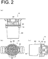
- FIG. 2(a) is a top view of the vehicle lighting fixture 10
- FIG. 2(b) is a front view thereof
- FIG. 2(c) is a side view thereof.
- the vehicle lighting fixture 10 shown in FIGS. 1 and 2 is a vehicle headlamp that is capable of forming a low-beam light distribution pattern P Lo (see FIG. 9(a) ) or a composite light distribution pattern including the low-beam light distribution pattern P Lo and an ADB (Adaptive Driving Beam) light distribution pattern P ADB (see FIG. 9(c) ), and that is mounted on the left and right sides of a front end portion of a vehicle (not shown).
- the low-beam light distribution pattern P Lo and the ADB light distribution pattern P ADB are formed on a virtual vertical screen facing the vehicle front (disposed in front of the vehicle front about 25 m away therefrom).
- XYZ axes are defined. The X-axis extends in the vehicle longitudinal direction, the Y-axis extends in the vehicle width direction, and the Z-axis extends in the vertical direction.
- FIG. 3 is a cross-sectional view of the vehicle lighting fixture 10 shown in FIG. 1 taken along a horizontal plane including a reference axis AX (a plane including the X-axis and Y-axis).
- FIG. 4 is a cross-sectional view of the vehicle lighting fixture 10 shown in FIG. 1 taken along a vertical plane including the reference axis AX (a plane including the X-axis and Z-axis).
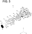
- FIG. 5 is an exploded perspective view of the vehicle lighting fixture 10.
- the vehicle lighting fixture 10 of the present embodiment includes a heat sink 20, a light source module 30, a holder 40, a separator 50, a primary lens 60, a retainer 70, a secondary lens 80, and the like.
- the vehicle lighting fixture 10, although not shown, is disposed in a lamp chamber constituted by an outer lens and a housing, and is attached to the housing or the like.
- the heat sink 20 includes a base 22 made of aluminum die cast and including a front surface 22a and a rear surface 22b on the opposite side.
- the front surface 22a includes a light source module mounting surface 22a1 and a peripheral surface 22a2 surrounding the light source module mounting surface 22a1.
- the light source module mounting surface 22a1 and the peripheral surface 22a2 are each, for example, a plane parallel to a plane including the Y-axis and the Z-axis.
- Screw holes 22a5 are provided in the light source module mounting surface 22a1 (in FIG. 5 , at three portions) in order to screw the light source module 30. Further, positioning pins 22a6 are provided to the light source module mounting surface 22a1 (in FIG. 5 , at two portions) in order to position the light source module 30,.
- the peripheral surface 22a2 includes a holder abutment surface 22a3 against which the holder 40 abuts, and a retainer abutment surface 22a4 against which the retainer 70 abuts.
- the retainer abutment surface 22a4 is provided on each of the left and right sides of the peripheral surface 22a2.
- the thickness between the retainer abutment surface 22a4 and the rear surface 22b is thicker than the thickness between the holder abutment surface 22a3 and the rear surface 22b (thickness in the X-axis direction), so as to constitute a step portion.
- Screw holes 22c into which screw N1 is inserted, are provided in the base 22 (in FIG. 3 , at two portions).
- the screw holes 22c penetrate the base 22 from the retainer abutment surface 22a4 to the rear surface 22b.
- First extension portions 24 are provided to the left and right sides of the base 22 to extend from the left and right sides of the base 22 rearward (X-axis direction). At the tip end portion of the first extension portion 24, a second extension portion 26 extending sideward (Y-axis direction) is provided.
- Heat dissipation fins 28 are provided to the rear surface 22b of the base 22.
- the light source module 30 includes a plurality of low-beam light sources 32a and a plurality of ADB light sources 32b, and a substrate 34 on which the plurality of low-beam light sources 32a, the plurality of ADB light sources 32b, and connectors 34c are mounted.
- FIG. 8(c) is a front view (perspective view) of the plurality of low-beam light sources 32a and the plurality of ADB light sources 32b when seen through the separator 50.
- the plurality of low-beam light sources 32a are mounted on the substrate 34 in a form in which they are arranged in the upper stage and along the Y-axis direction.
- the plurality of ADB light sources 32b are mounted on the substrate 34 in a form in which they are arranged in the lower stage and along the Y-axis direction.
- Each of the light sources 32a, 32b is, for example, a semiconductor light emitting element such as an LED or LD with a light emitting surface of a rectangular (e.g., 1 mm square), and is mounted on the substrate 34 in a state in which the respective light emitting surface is directed forward (front).
- a plurality of rectangles in FIG. 8(c) represent the light emitting surfaces of the respective light sources 32a and 32b.
- the substrate 34 there are provided through holes 34a into which positioning pins 22a6 of the heat sink 20 are inserted (in FIG. 5 , at two portions) and notches S1 in which screws N2 are inserted (in FIG. 5 , at three portions).
- a light source module 30 with the above-described configuration is fixed to the heat sink 20 by screwing the screws N2 inserted into the notches S1 to the screw holes 22a5 of the heat sink 20 (the light source module mounting surface 22a1), while the positioning pins 22a6 of the heat sink 20 are inserted into the through holes 34a of the substrate 34.
- the holder 40 is made of a synthetic resin such as an acrylic resin or a polycarbonate resin, and includes a cup-shaped holder main body 42 in which a front side is opened and a rear side is closed.
- the holder body 42 has a front surface 42a that is configured as a surface with the following shape (or a concave spherical surface to the rear).
- the front surface 42a is formed by inverting the rear surface of the separator 50 so that the rear surface of the separator 50 (rear surface 52b of the upper separator body 52 and the rear surface 53b of the lower separator body 53) is in surface contact with the front surface 42a.
- a through hole 42c in which the first light guide portion 52d and the second light guide portion 53d of the separator 50 are inserted is provided.
- a cylindrical portion 44 extending toward the rear (X-axis direction) from the outer peripheral portion of the holder body 42 is provided. Then, at the tip end portion of the cylindrical portion 44, a flange portion 46 to abut against the holder abutment surface 22a3 of the heat sink 20 is provided.
- a notch S4 is provided in the holder main body 42 (and the cylindrical portion 44).
- projected portions 48 and projected portions 49 are provided on the front side open end surface 40a of the holder 40.
- FIG. 6 is a perspective view of a structure which has the heat sink 20, the light source module 30, the holder 40, and the separator 50 in combination.
- FIG. 7 is a perspective view of the separator 50.
- the separator 50 is a cup-shaped member made of a silicone resin and which has an open front side and a closed rear side.
- the separator 50 includes an upper separator body 52 and a lower separator body 53.
- the upper separator body 52 is disposed above the reference axis AX, and the lower separator body 53 is disposed below the reference axis AX.
- the reference axis AX extends in the X-axis direction.
- the upper separator body 52 has a front surface 52a that is configured as a surface with a shape (concave spherical surface to the rear) that is formed by inverting the upper half of the rear surface 60b of the primary lens 60 so that the upper half, above the reference axis AX, of the rear surface 60b of the primary lens 60 (convex spherical surface to the rear) is in surface contact with the front surface 52a.
- the upper separator body 52 has a rear surface 52b (see FIGS. 3 and 4 ) that is configured as a surface with a shape (convex spherical surface to the rear) that is formed by inverting the upper half of the front surface 42a of the holder 40 (holder body 42) so that the upper half, above the reference axis AX, of the front surface 42a (concave spherical surface to the front) of the holder 40 (holder body 42) is in surface contact with the rear surface 52b.
- the lower edge of the front surface 52a of the upper separator body 52 includes a stepped edge portion 52a1 with the shape corresponding to a cut-off line CL Lo (CL1 to CL3) and extended edge portions 52a2 and 52a3 disposed on both sides of the stepped edge portion 52a1.
- the extended edge portion may be provided on only one side.
- the stepped edge portion 52a1 includes a side e1 corresponding to the left horizontal cut-off line CL1, a side e2 corresponding to the right horizontal cut-off line CL2, and a side e3 corresponding to the oblique cut-off line CL3 connecting the left horizontal cut-off line CL1 and the right horizontal cut-off line CL2.
- the extended edge portion 52a2 is disposed at the same position as the side e1 with respect to the Z-axis direction.
- the extended edge portion 52a3 is disposed at the same position as the side e2 with respect to the Z-axis direction.
- the upper separator body 52 has a lower end surface 52c (see FIG. 4 ).
- the lower end surface 52c is a surface extending from the lower edge of the front surface 52a of the upper separator body 52 toward the rear surface 52b of the upper separator body 52 in the horizontal direction (X-axis direction).
- a first light guide portion 52d is provided to the rear surface 52b of the upper separator body 52.
- the first light guide portion 52d has a proximal end portion that is provided in a partial region including the stepped edge portion 52a1 of the rear surface 52b of the upper separator body 52, and extends toward the light source module 30 (the plurality of low-beam light sources 32a).
- the partial region including the stepped edge portion 52a1 is a region where the light source module 30 (the light emitting surfaces of the plurality of low-beam light sources 32a) faces the rear surface 52b of the upper separator body 52.
- the first light guide portion 52d is inserted into the through hole 42c of the holder 40.
- a first light incident surface 52e is provided at the tip end portion of the first light guide portion 52d.
- the first light incident surface 52e is, for example, a plane parallel to a plane including the Y-axis and the Z-axis.
- the first light incident surface 52e is disposed at a position where it faces the light source module 30 (the light emitting surfaces of the plurality of low-beam light sources 32a) (see FIG. 4 ) in a state in which the first light guide portion 52d is inserted into the through hole 42c of the holder 40.
- the distance between the first light incident surface 52e and the light source module 30 (the light emitting surfaces of the plurality of low-beam light sources 32a) is, for example, 0.2 mm.
- a flange portion 52f is provided to the front side open end surface of the upper separator body 52.
- the flange portion 52f has a through hole 52f1 into which the projected portion 48 of the holder 40 is inserted (in FIGS. 5 and 7 , at one portion), and through holes 52f2 into which the projected portions 49 of the holder 40 are inserted (in FIGS. 5 and 7 , at two portions).
- the lower separator body 53 has a front surface 53a that is configured as a surface with a shape (concave spherical surface to the rear) that is formed by inverting the lower half of the rear surface 60b of the primary lens 60 so that the lower half, below the reference axis AX, of the rear surface 60b of the primary lens 60 (convex spherical surface to the rear) is in surface contact with the front surface 53a.
- the lower separator body 53 has a rear surface 53b (see FIGS. 3 and 4 ) that is configured as a surface with a shape (convex spherical surface to the rear) that is formed by inverting the lower half of the front surface 42a of the holder 40 (holder body 42) so that the lower half, below the reference axis AX, of the front surface 42a (concave spherical surface to the front) of the holder 40 (holder body 42) is in surface contact with the rear surface 53b.
- a shape convex spherical surface to the rear
- the upper edge of the front surface 53a of the lower separator body 53 includes a stepped edge portion 53a1 (sides e1' to e3') with a shape obtained by inverting the stepped edge portion 52a1, and extended edge portions 53a2 and 53a3 disposed on both sides of the stepped edge portion 53a1.
- the extended edge portion may be provided on only one side.
- the extended edge portion 53a2 is disposed at the same position as the side e1' with respect to the Z-axis direction.
- the extended edge portion 53a3 is disposed at the same position as the side e2' with respect to the Z-axis direction.
- the lower separator body 53 has an upper end surface 53c (see FIG. 4 ).
- the upper end surface 53c is a surface extending from the upper edge of the front surface 53a of the lower separator body 53 toward the rear surface 53b of the lower separator body 53 in the horizontal direction (X-axis direction).
- a second light guide portion 53d is provided to the rear surface 53b of the lower separator body 53.
- the second light guide portion 53d has a proximal end portion that is provided in a partial region including the stepped edge portion 53a1 of the rear surface 53b of the lower separator body 53, and extends toward the light source module 30 (the plurality of ADB light sources 32b).
- the partial region including the stepped edge portion 53a1 is a region where the light source module 30 (the light emitting surfaces of the plurality of ADB light sources 32b) faces the rear surface 53b of the lower separator body 53.
- the second light guide portion 53d is inserted into the through hole 42c of the holder 40.
- a second light incident surface 53e is provided at the tip end portion of the second light guide portion 53d.
- the second light incident surface 53e is a surface adjusted such that a plurality of regions constituting the ADB light distribution pattern (e.g., a plurality of regions A1 to A4 which are individually turned on and off) are prevented from becoming circular and overlapping with each other as shown in FIG. 9(d) , and such that, as shown in FIG.9 (b) the regions are formed in a state of being divided by vertical edges.
- FIGS. 9(b) and 9(d) show an ADB light distribution pattern formed when four ADB light sources 32b are provided. The hatched areas in FIGS. 9(b) and 9(d) indicate that the ADB light sources 32b corresponding to the area are turned off.
- the second light incident surface 53e is disposed at a position where it faces the light source module 30 (the light emitting surfaces of the plurality of ADB light sources 32b) (see FIG. 4 ) in a state in which the second light guide portion 53d is inserted into the through hole 42c of the holder 40.
- the distance between the second light incident surface 53e and the light source module 30 (the light emitting surfaces of the plurality of ADB light sources 32b) is, for example, 0.2 mm.
- a flange portion 53f is provided to the front side open end surface of the lower separator body 53.
- the flange portion 53f has through holes 53f1 into which the projected portions 48 of the holder 40 are inserted (in FIGS. 5 and 7 , at two portions).
- the lower separator body 53 has a notch S5 so that the connectors 34c of the light source module 30 do not abut against (interfere with) the lower separator body 53.
- the upper separator body 52 and the lower separator body 53 constitute the separator 50 in combination in a state in which the lower edge of the front surface 52a of the upper separator body 52 and the upper edge of the front surface 53a of the lower separator body 53 are in line contact with each other and the lower end surface 52c of the upper separator body 52 and the upper end surface 53c of the lower separator body 53 are in surface contact with each other.
- the separator 50 with the above-described configuration is disposed in such a manner that the first light guide portion 52d of the upper separator body 52 and the second light guide portion 53d of the upper separator body 52 are inserted into the through holes 42c of the holder 40 (e.g., press-fit or fit), that the first light incident surface 52e of the upper separator body 52 (the first light guide portion 52d) and the light source module 30 (the light emitting surfaces of the plurality of low-beam light sources 32a) face each other and the second light incident surface 53e of the lower separator body 53 (the second light guide portion 53d) and the light source module 30 (the light emitting surfaces of the plurality of ADB light sources 32b) face each other (see FIGS.
- the projected portions 48 of the holder 40 are inserted into the through hole 52f1 of the upper separator body 52 and the through holes 53f1 of the lower separator body 53 (see FIG. 6 ). Furthermore, the projected portions 49 of the holder 40 are also inserted into the through holes 52f2 of the upper separator body 52 (see FIG. 6 ).
- the primary lens 60 is a spherical lens that includes a front surface 60a and a rear surface 60b on an opposite side thereof.
- the front surface 60a is a spherical surface convex to the front
- the rear surface 60b is a spherical surface convex to the rear.
- the primary lens 60 includes a flange portion 62. The flange portion 62 extends between the front surface 60a and the rear surface 60b so as to surround the reference axis AX.
- the retainer 70 includes a retainer body 72 that is made of a synthetic resin such as an acrylic resin or a polycarbonate resin and that includes a cylindrical body that widens in a conical shape from the front side open end surface toward the rear side open end surface.
- a synthetic resin such as an acrylic resin or a polycarbonate resin
- the secondary lens 80 is made of a synthetic resin such as an acrylic resin or a polycarbonate resin, and includes a lens body 82.
- the lens body 82 includes a front surface 82a and a rear surface 82b on the opposite side thereto (see FIGS. 3 and 4 ).
- the front surface 82a is a plane parallel to the plane including the Y-axis and the Z-axis
- the rear surface 82b is a convex spherical surface to the rear.
- a cylindrical portion 84 extending from the outer peripheral portion of the lens body 82 toward the rear (X-axis direction) is provided.
- the primary lens 60 and the secondary lens 80 constitute a projection lens with a focal point F (see FIG. 8 (c) ) located in the vicinity of the lower edge (the stepped edge portion 52a1) of the front surface 52a of the upper separator body 52 and the upper edge (the stepped edge portion 53a1) of the front surface 53a of the lower separator body 53.
- the curvature of field of the projection lens substantially coincides with the lower edge (the stepped edge portion 52a1) of the front surface 52a of the upper separator body 52 and the upper edge (the stepped edge portion 53a1) of the front surface 53a of the lower separator body 53.
- the primary lens 60 and the secondary lens 80 constituting the projection lens for example, a spherical lens and a plano-convex lens described in Japanese Patent Application Laid-Open No. 2015-79660 may be used.
- the secondary lens 80 with the above-described configuration has the lens body 82 disposed in front of the primary lens 60, and a pressing and screw receiving portion 86 disposed in contact with the flange portion 76 of the retainer 70 (see FIGS. 3 and 4 ).
- the luminous intensity distribution corresponding to the low-beam light distribution pattern is formed on the front surface 52a of the upper separator body 52.
- the luminous intensity distribution includes the sides e1 to e3 (see FIG. 8A ) corresponding to the cut-off line CL Lo (CL1 to CL3).
- the projection lens which is constituted by the primary lens 60 and the secondary lens 80, reverses and projects this luminous intensity distribution forward.
- this forms the low-beam light distribution pattern P Lo including the cut-off line CL (CL1 to CL3) at the upper edge.
- the plurality of ADB light sources 32b When the plurality of ADB light sources 32b are turned on, light from the plurality of ADB light sources 32b is incident on the second light incident surface 53e of the second light guide portion 53d of the lower separator body 53, is guided within the second light guide portion 53d, and is outputted from the front surface 53a of the lower separator body 53. As a result, the luminous intensity distribution corresponding to the ADB light distribution pattern is formed on the front surface 53a of the lower separator body 53.
- the luminous intensity distribution includes the sides e1' to e3' (see FIG. 8(b) ) corresponding to the cut-offline CL ADB (CL1' to CL3'.
- the projection lens which is constituted by the primary lens 60 and the secondary lens 80, reverses and projects this luminous intensity distribution forward.
- this forms the ADB light distribution pattern P ADB including the cut-offline CL ADB (CL1' to CL3') at the lower edge.
- FIG. 9(b) shows the ADB light distribution patterns P ADB formed when the number of the plurality of ADB light sources 32b is four. The hatched area in FIG. 9(b) indicates that the ADB light sources 32b corresponding to that area are turned off.
- the composite light distribution pattern including the low-beam light distribution pattern P Lo and the ADB light distribution pattern P ADB is formed as shown in FIG. 9(c) .
- the present inventors have studied and found that the vehicle lighting fixture 10 with the above-described configuration, although satisfying the legal requirements for the low-beam light distribution pattern, forms the low-beam light distribution pattern with a portion (e.g., a portion around 4 degrees below the horizontal line) whose luminous intensity becomes relatively high, and, for example, causes luminous intensity unevenness (luminance unevenness), resulting in reducing the light distribution feeling.
- a portion e.g., a portion around 4 degrees below the horizontal line
- luminous intensity unevenness luminance unevenness
- the reason why the luminous intensity at a portion of the low-beam light distribution pattern (e.g., a portion around 4 degrees below the horizontal line) becomes high is that, of the light from the low-beam light source 32a, light whose luminous intensity is relatively strong (e.g., light in a narrow angle direction with respect to an optical axis AX32a of the low-beam light source 32a (see FIG. 4 )) is projected to a portion (e.g., a portion around 4 degrees below the horizontal line) of the low-beam light distribution pattern P Lo by the projection lens constituted by the primary lens 60 and the secondary lens 80.
- FIG. 10 is a diagram showing an example using a separator without an upper separator body 52 but with only a first light guide portion 52d (the same light guide lens as that used in the above-described conventional art).
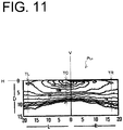
- FIG. 10 when a separator without an upper separator body 52 but with only the first light guide portion 52d is used as the separator 50, it has been found that the luminous intensity at a portion of the low-beam light distribution pattern P Lo (e.g., a portion around 4 degrees below the horizontal line) becomes relatively high, and in addition, as shown in FIG. 11 , the thickness TC of the central portion of the low-beam light distribution pattern P Lo becomes thin as compared with the thicknesses TL and TR of both left and right sides thereof, resulting in reduction in the light distribution feeling.
- FIG. 11 is a diagram showing an example of a low-beam light distribution pattern P Lo formed when a separator without an upper separator body 52 but with only the first light guide portion 52d is used.
- the thickness of the upper separator body 52 along the reference axis AX with respect to the horizontal direction become thicker as it moves away from the reference axis AX (see thicknesses T1 and T2 in FIG. 3 ), and second, as the light from the low-beam light source 32a that transmits the upper separator body 52 through the thicker portion of the upper separator body 52, the optical path length within the upper separator body 52 becomes longer, and thus the light is outputted from the front surface 52a of the upper separator body 52 while being greatly diffused in the vertical direction.
- a portion farther from the reference axis AX is thicker than the portion closer to the reference axis AX (e.g., the portion with the thickness T1 in FIG. 3 ). Therefore, the light from the low-beam light source 32a that transmits the upper separator body 52 through a portion farther from the reference axis AX (e.g., a portion with the thickness T2 in FIG.
- the thickness TC of the central portion of the low-beam light distribution pattern P Lo is smaller than the thicknesses TL and TR of the left and right sides.
- the present inventors have studied this matter and found that: when the low-beam light distribution pattern is required to have a long length in the vertical direction, a lower density (narrow bright range), and a low maximum luminous intensity as compared with the ADB light distribution pattern, as shown in FIG.
- the focal plane FP of the projection lens 90 and the front surface 52a of the separator 50 through which light from the low-beam light source 32a is outputted are each spherical (a spherical surface of constant curvature) and coincide with each other (in surface contact with each other)
- the focal plane FP of the projection lens 90 and the front surface 53a of the separator 50 through which the light from the ADB light source 32b is outputted are each spherical (a spherical surface of constant curvature) and coincide with each other (in surface contact with each other)
- the focal plane FP of the projection lens 90 and the front surface 53a of the separator 50 through which the light from the ADB light source 32b is outputted are each spherical (a spherical surface of constant curvature) and coincide with each other (in surface contact with each other)
- the low-beam light distribution pattern P Lo and the ADB light distribution pattern P ADB have vertically
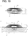
- FIG. 19(a) shows an example of an ADB light distribution pattern and a low-beam light distribution pattern formed when using the separator shown in FIG. 10 (the same light guide lens as that used in the above-described conventional art).
- a vehicle lighting fixture 10A capable of preventing the luminous intensity at a portion (e.g., a portion around 4 degrees below the horizontal line) of the low-beam light distribution pattern from becoming relatively high, and also capable of forming a low-beam light distribution pattern with a uniform vertical thickness with respect to the horizontal direction (i.e., it is possible to suppress the light distribution feeling from being reduced) will be described.
- "uniform” used in this specification is not limited to the meaning of the term uniform in a strict sense. That is, it is considered as being “uniform” as long as it can be visually evaluated as being uniform or substantially uniform.
- the vehicle lighting fixture 10A of the present embodiment is different from the vehicle lighting fixture 10 of the above-described first embodiment in that a separator 50A is used instead of the separator 50, and a primary lens 60A is used instead of the primary lens 60. Except for this, the configuration thereof is the same as that of the above-described first embodiment.
- a separator 50A is used instead of the separator 50
- a primary lens 60A is used instead of the primary lens 60.
- the configuration thereof is the same as that of the above-described first embodiment.
- differences from the above-described first embodiment will be mainly described, and the same components are denoted by the same reference numerals, and descriptions thereof will be omitted as appropriate.
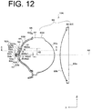
- FIG. 12 is a cross-sectional view of the vehicle lighting fixture 10A taken along a vertical plane including the reference axis AX (plane including the X-axis and Z-axis).
- FIG. 13 is a cross-sectional view of the vehicle lighting fixture 10A shown in FIG. 12 taken along line A-A. It should be noted that the heat sink 20, the holder 40, the retainer 70 and the like are not illustrated in FIGS. 12 and 13 .
- the vehicle lighting fixture 10A includes the secondary lens 80, a primary lens 60A disposed behind the secondary lens 80, a separator 50A disposed behind the primary lens 60A, a plurality of low-beam light sources 32a (hereinafter, which may be simply referred to as low-beam light source(s) 32a) that are disposed behind the separator 50A and emit light for forming a low-beam light distribution pattern by being irradiated forward through the separator 50A, the primary lens 60A, and the secondary lens 80 in this order, and a plurality of ADB light sources 32b (hereinafter, which may be simply referred to as ADB light source(s) 32b) that emit light for forming an ADB light distribution pattern by being irradiated forward through the separator 50A, the primary lens 60A, and the secondary lens 80 in this order.
- ADB light sources 32b hereinafter, which may be simply referred to as ADB light source(s) 32b
- the low-beam light sources 32a, the ADB light sources 32b, the separator 50A, the primary lens 60A, and the secondary lens 80 are held by the heat sink 20, the holder 40, the retainer 70 and the like to maintain the positional relationship shown in FIG. 12 .
- the secondary lens 80 (the front surface 82a and the rear surface 82b) and the primary lens 60A (the front surface 60a) constitute a projection lens 90.
- the projection lens 90 is constituted by, out of one or a plurality of lenses (in this embodiment, the primary lens 60A and the secondary lens 80), the optical surface(s) (in this embodiment, the front surface 60a of the primary lens 60A and the front surface 82a and rear surface 82b of the secondary lens 80) other than the rear surface of the rearmost lens (in this embodiment, the rear surface 60Ab of the primary lens 60A).
- the focal plane FP of the projection lens 90 is, for example, a spherical surface with a constant curvature (see FIG. 20 ).
- the focal point F of the projection lens 90 is located between the lower edge of the front surface 52Aa of the upper separator body 52A and the upper edge of the front surface 53a of the lower separator body 53 in the vertical direction. Further, the focus F of the projection lens 90, although not shown, is located at the center of the lower edge of the front surface 52Aa of the upper separator body 52A (and the upper edge of the front surface 53a of the lower separator body 53) with respect to the horizontal direction.
- the reference axis AX passes through the focal point F, and extends in the vehicle longitudinal direction (X direction).
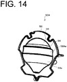
- FIG. 14 is a perspective view of the separator 50A
- FIG. 15(a) is a top view of the separator 50A
- FIG. 15(b) is a rear view thereof
- FIG. 15(c) is a bottom view thereof
- FIG. 15(d) is a side view thereof.
- the separator 50A is made of a silicon resin, and is a cup-shaped member in which a front side is opened and a rear side is closed, as shown in FIG. 14 and the like.
- the separator 50A includes an upper separator body 52A, a first light guide portion 52d, a first extension portion 54, a second extension portion 55, a lower separator body 53, a second light guide portion 53d, and a flange portion 56, which are configured as a single part integrally molded.
- the upper separator body 52A is disposed above the reference axis AX, and the lower separator body 53 is disposed below the reference axis AX.
- the upper separator body 52A is a thin plate-shaped light guide portion including a front surface 52Aa and a rear surface 52Ab on the opposite side thereof.
- the upper separator body 52A is a thin plate-shaped light guide portion, in a horizontal cross-section, curved along the rear surface 60Ab (the upper light incident surface 60Ab1) of the primary lens 60A (see FIG. 13 ), and, in a vertical cross-section, extending upward (see FIG. 12 ).
- the lower edge of the front surface 52Aa of the upper separator body 52A includes a stepped edge portion 52a1 (not shown in FIG. 12 ) with a shape corresponding to the cut-off line CL Lo (CL1 to CL3, as in the first embodiment described above.
- the upper separator body 52A is disposed in a state in which the front surface 52Aa faces the rear surface 60Ab (the upper light incident surface 60Ab1) of the primary lens 60A.
- the lower portion of the front surface 52Aa of the upper separator body 52A is in surface contact with the lower portion of the rear surface 60Ab (the upper light incident surface 60Ab1) of the primary lens 60A. Further, a space S is formed between a portion above the lower portion of the front surface 52Aa of the upper separator body 52A and a portion above the lower portion of the rear surface 60Ab (the upper light incident surface 60Ab1) of the primary lens 60A.
- the distance (space S) between the front surface 52Aa of the upper separator body 52A and the rear surface 60Ab (the upper light incident surface 60Ab1) of the primary lens 60A increases upward.
- a relationship between the front surface 52Aa of the upper separator body 52A and the rear focal plane FP of the projection lens 90 (curvature of field. see FIG. 12 ) is also the same.
- the light from the low-beam light sources 32a outputted from the first light guide portion 52d of the upper separator body 52A becomes diffused light
- the light reaching the rear surface 60Ab (the upper light incident surface 60Ab1) of the primary lens 60A weakens as the distance (space S) between the front surface 52Aa of the upper separator body 52A and the rear surface 60Ab (the upper light incident surface 60Ab1) of the primary lens 60A becomes wider (i.e., upward from the reference axis AX).
- the low-beam light distribution pattern becomes an ideal luminous intensity distribution that decreases in a gradation manner from the upper edge downward.
- the vertical length H1 (see FIG. 12 ) of the portion (surface contact portion) where the lower portion of the front surface 52Aa of the upper separator body 52A and the lower portion of the rear surface 60b (the upper light incident surface 60Ab1) of the primary lens 60A are in surface contact with each other is, for example, 0.7 mm.
- the provision of the surface contact portion can form a high luminous intensity band with a relatively high luminous intensity in the vicinity of the cut-off line of the low-beam light distribution pattern. Further, the adjustment of the length H1 can adjust the vertical length of the high luminous intensity band.
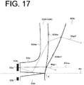
- the front surface 52Aa of the upper separator body 52A is configured to be, for example, a slightly convex curved surface to the front such that the light from the low-beam light sources 32a to be guided through the upper separator body 52A while being repeatedly totally reflected between the front surface 52Aa and the rear surface 52Ab of the upper separator body 52A is outputted from the front surface 52Aa of the upper separator body 52A (see FIG. 17 ).
- the rear surface 52Ab of the upper separator body 52A is also configured to be a slightly convex curved surface similarly to the front.
- the thickness T of the upper separator body 52A is, for example, 2 mm in consideration of moldability and the like.
- the vertical length H2 of the upper separator body 52A is, for example, 7 mm in consideration of the vertical length (thickness) of the low-beam light distribution pattern.
- the adjustment of the length H2 can adjust the vertical length of the low-beam light distribution pattern.
- the first light guide portion 52d is a thin plate-shaped light guide portion including an upper surface 52d1 and a lower surface 52d2 on the opposite side thereof.
- the first light guide portion 52d extends from the lower portion of the upper separator body 52A (rear surface 52Ab) toward the low-beam light sources 32a, and has a first light incident surface 52e provided at the tip end thereof and facing the low-beam light sources 32a.
- the first light incident surface 52e is a surface through which the light from the low-beam light sources 32a enters the separator 50A (the first light guide portion 52d), and is, for example, a plane parallel to a plane including the Y-axis and the Z-axis.
- the first extension portion 54 and the second extension portion 55 are so-called bridging portions for which no optical function is intended.
- the first extension portion 54 extends from the upper end portion of the upper separator body 52A toward the front.
- the second extension portion 55 extends from the front end portion of the first extension portion 54 along the rear surface 60Ab of the primary lens 60A.
- the lower separator body 53 is a thin plate-shaped light guide portion including a front surface 53a and a rear surface 53b on the opposite side thereof.
- the upper edge of the front surface 53a of the lower separator body 53 includes a stepped edge portion 53a1 of the shape obtained by inverting the stepped edge portion 52a1, similarly to the above-described first embodiment (not shown in FIG. 12 ).
- the second light guide portion 53d extends from the upper portion of the lower separator body 53 (rear surface 53b) toward the ADB light sources 32b and has a second light incident surface 53e provided at the tip end thereof and facing the ADB light sources 32b.
- the second light incident surface 53e is a surface through which the light from the ADB light sources 32b enters the separator 50A (the second light guide portion 53d) and is, for example, a plane parallel to a plane including the Y-axis and Z-axis.
- FIG. 16 shows an example of a holding structure for the separator 50A and the primary lens 60A.
- the separator 50A with the above-described configuration is interposed between the holder 40 and the retainer 70 together with the primary lens 60A.
- the first light guide portion 52d and the second light guide portion 53d are inserted into the through holes 42c of the holder 40, and the separator 50A is interposed between the holder 40 and the retainer 70 together with the primary lens 60A in such a state that the first light incident surface 52e and the low-beam light sources 32a (the light emitting surfaces) face each other, the second light incident surface 53e and the ADB light sources 32b (the light emitting surfaces) face each other, and the rear surface (the rear surfaces 52Ab and 53b, etc.) of the separator 50A is in surface contact with the front surface 42a of the holder 40 (the holder body 42).
- the primary lens 60A is made of a transparent resin such as an acrylic resin or a polycarbonate resin, and is a spherical lens including a front surface 60a and a rear surface 60Ab on the opposite side thereof as shown in FIG. 12 .
- the front surface 60a is a spherical surface convex to the front
- the rear surface 60Ab is a spherical surface convex to the rear.
- the primary lens 60A is provided with a flange portion 62, which extends so as to surround the reference axis AX between the front surface 60a and the rear surface 60Ab.
- the rear surface 60Ab of the primary lens 60A includes an upper light incident surface 60Ab1 disposed above the reference axis AX and a lower light incident surface 60Ab2 disposed below the reference axis AX.
- the upper light incident surface 60Ab1 is a surface through which light from the low-beam light sources 32a outputted from the front surface 52Aa of the upper separator body 52A enters the primary lens 60A.
- the upper light incident surface 60Ab1 is provided in a region of the rear surface 60Ab of the primary lens 60A to which the front surface 52Aa of the upper separator body 52A faces.
- the lower portion of the upper light incident surface 60Ab1 coincides with the rear focal plane FP of the projection lens 90.
- the portion above the lower portion of the upper light incident surface 60Ab1 does not coincide with the rear focal plane FP of the projection lens 90, but is inclined forward with respect to the rear focal plane FP.
- the surface shape of the upper light incident surface 60Ab1 is adjusted in such a manner that it satisfies the legal requirements required for the low-beam light distribution pattern, luminous intensity at a portion (e.g., a portion around 4 degrees below the horizontal line) of the low-beam light distribution pattern can be suppressed from becoming relatively high, and the thickness of the pattern in the vertical direction becomes uniform with respect to the horizontal direction (i.e., it is possible to suppress the light distribution feeling from being reduced).
- the surface shape of the upper light incident surface 60Ab1 is adjusted in such a manner that the luminous intensity distribution of the low-beam light distribution pattern decreases in a gradation manner from the upper edge of the low-beam light distribution pattern downward. It should be noted that in some cases, the surface shape of the front surface 52Aa of the upper separator body 52A may be adjusted in the same manner.
- the surface shape of the upper light incident surface 60Ab1 that forms the low-beam light distribution pattern - that satisfies the legal requirements required for the low-beam light distribution pattern, is capable of suppressing luminous intensity at a portion (e.g., a portion around 4 degrees below the horizontal line) of the low-beam light distribution pattern from becoming relatively high, and uniforms the thickness of the pattern in the vertical direction with respect to the horizontal direction, (i.e., it is possible to suppress the light distribution feeling from being reduced) - by, for example, using a predetermined simulation software to adjust the surface shape of the upper light incident surface 60Ab1, and by, each time it is adjusted, confirming the low-beam light distribution pattern (luminous intensity distribution, etc.).
- the lower light incident surface 60Ab2 is a surface through which light from the ADB light sources 32b outputted from the front surface 53a of the lower separator body 53 enters the primary lens 60A.
- the lower light incident surface 60Ab2 is provided in a region of the rear surface 60Ab of the primary lens 60A to which the front surface 53a of the lower separator body 53 faces.
- the lower light incident surface 60Ab2 coincides with the rear focal plane FP of the projection lens 90.
- the primary lens 60A with the above-described configuration is interposed between the holder 40 and the retainer 70 together with the separator 50A.
- the primary lens 60A with the above-described configuration is interposed between the holder 40 and the retainer 70 together with the separator 50A in such a state that the flange portion 62 is in contact with the flange portion 56 of the separator 50A, a portion of the rear surface 60Ab is in surface contact with the second extension portion 55 of the separator 50A, the lower portion of the rear surface 60Ab (the upper light incident surface 60Ab1) is in surface contact with the lower portion of the front surface 52Aa of the upper separator body 52A, the rear surface 60Ab (the lower light incident surface 60Ab2) is in surface contact with the front surface 53a of the lower separator body 53, and a space S is formed between the front surface 52Aa of the upper separator body 52 and the rear surface 60Ab (the upper light incident surface 60Ab1) of the primary lens 60A.
- FIG. 20 is a diagram for describing the relationship between the upper light incident surface 60Ab1 and the lower light incident surface 60Ab2 of the primary lens 60A and the focal plane FP of the projection lens 90.
- the lower portion of the upper light incident surface 60Ab1 of the primary lens 60A and the upper portion of the lower light incident surface 60Ab2 of the primary lens 60A are defined as a first region B1
- a portion above the lower portion of the upper light incident surface 60Ab1 of the primary lens 60A is defined as a second region B2
- a portion below the upper portion of the lower light incident surface 60Ab2 of the primary lens 60A is defined as a third region B3.
- the first region B1 coincides with the focal plane FP of the projection lens 90
- the second region B2 is disposed forward with respect to the focal plane FP of the projection lens 90 (or rearward)
- the third region B3 is disposed rearward with respect to the focal plane FP of the projection lens 90 (or forward).
- the distance between the second region B2 and the focal plane FP of the projection lens 90 becomes wider upward from the reference axis AX.
- the distance between the third region B3 and the focal plane FP of the projection lens 90 becomes wider downward from the reference axis AX.
- the adjustment of the first region B1 can adjust the vertical length of the relatively high luminous intensity band with a relative high luminous intensity near the cut-off line of the low-beam light distribution pattern and the vertical length of the relatively high luminous intensity band with a relative high luminous intensity near the lower edge of the ADB light distribution pattern.
- the adjustment of the second region B2 can adjust the vertical length of the low-beam light distribution pattern.
- the adjustment of the third region B3 can adjust the vertical length of the ADB light distribution pattern.
- the secondary lens 80 is made of a transparent resin such as an acrylic resin or a polycarbonate resin, and is a plano-convex lens including a front surface 82a and a rear surface 82b on the opposite side thereof.
- the front surface 82a is a plane parallel to the plane including the Y-axis and Z-axis
- the rear surface 82b is a convex spherical surface to the rear.
- FIG. 17 is a diagram for explaining an optical path of light from the low-beam light sources 32a.
- a part of light for example, light Ray1 with a relatively strong luminous intensity (e.g., light in the narrow angle direction with respect to the optical axis AX32a of the low-beam light sources 32a) is directly outputted from the lower portion of the front surface 52Aa of the upper separator body 52A, further enters the primary lens 60A through the upper light incident surface 60Ab1 of the primary lens 60A, and is projected by the projection lens 90 constituted by the primary lens 60A and the secondary lens 80, to be used for forming the low-beam light distribution pattern.
- a relatively strong luminous intensity e.g., light in the narrow angle direction with respect to the optical axis AX32a of the low-beam light sources 32a
- another part of light for example, light Ray2 with a relatively weak luminous intensity (e.g., light in the wide angle direction with respect to the optical axis AX32a of the low-beam light sources 32a) is guided within the upper separator body 52A while being repeatedly totally reflected between the front surface 52Aa and the rear surface 52Ab of the upper separator body 52A to be outputted through the front surface 52Aa of the upper separator body 52A, further enters the primary lens 60A through the upper light incident surface 60Ab1 of the primary lens 60A, and is projected by the projection lens 90 constituted by the primary lens 60A and the secondary lens 80, to be used for forming the low-beam light distribution pattern.
- a relatively weak luminous intensity e.g., light in the wide angle direction with respect to the optical axis AX32a of the low-beam light sources 32a
- FIG. 27 is a graph showing the luminous intensity distribution of light that is guided within the upper separator body 52A while being repeatedly totally reflected between the front surface 52Aa and the rear surface 52Ab of the upper separator body 52A to be outputted through the front surface 52Aa of the upper separator body 52A.
- the present inventors have confirmed that the low-beam light distribution pattern formed as described above satisfies the legal requirements for the low-beam light distribution pattern, as shown in FIG. 18 , the luminous intensity at a portion (e.g., a portion around 4 degrees below the horizontal line H) of the low-beam light distribution pattern can be suppressed from becoming relatively high, and the thickness of the pattern in the vertical direction with respect to the horizontal direction becomes uniform (i.e., thicknesses TC, TL, and TR become uniform, so that the light distribution feeling can be prevented from being reduced).
- FIG. 18 shows an example of a low-beam light distribution pattern P Lo formed by the vehicle lighting fixture 10A.
- the space S is formed between the front surface 52Aa of the upper separator body 52A and the rear surface 60Ab (the upper light incident surface 60Ab1) of the primary lens 60A, the light Ray1 with the relatively strong luminous intensity out of the light from the low-beam light sources 32a that has entered the separator 50A (the first light guide portion 52d) is refracted (diffused), and further, Fresnel reflected each time when it is outputted through the front surface 52Aa of the upper separator body 52A and when the light enters the primary lens 60A through the rear surface 60Ab (the upper light incident surface 60Ab1) of the primary lens 60A.
- the portion e.g., a portion around 4 degrees below the horizontal line
- the space S is formed between the front surface 52Aa of the upper separator body 52A and the rear surface 60Ab (the upper light incident surface 60Ab1) of the primary lens 60A, the light Ray1 with the relatively strong luminous intensity out of the light from the low-beam light sources 32a that has entered the separator 50A (the first light guide portion 52d) is refracted (diffused) when entering the primary lens 60A through the rear surface 60Ab (the upper light incident surface 60Ab1) of the primary lens 60A, and a part of the light is projected to a portion (mainly, the lower region of the central portion) with a relatively low luminous intensity in the low-beam light distribution pattern by the projection lens 90 constituted by the primary lens 60A and the secondary lens 80.
- the light from the low-beam light sources 32a guided within the upper separator body 52A while being repeatedly totally reflected between the front surface 52Aa and the rear surface 52Ab of the upper separator body 52A and outputted from the front surface 52Aa of the upper separator body 52A is projected to a portion (mainly, the lower region of the central portion) with a relatively low luminous intensity in the low-beam light distribution pattern by the projection lens 90 constituted by the primary lens 60A and the secondary lens 80.
- the present inventors have confirmed that the low-beam light distribution pattern formed as described above has a longer vertical length (T3 ⁇ T4 in FIG. 19(b) ), a lower density (narrower bright range), and a lower maximum luminous intensity than the ADB light distribution pattern P ADB , as shown in FIG. 19(b).
- FIG. 19(b) shows an example of the ADB light distribution pattern and the low-beam light distribution pattern formed when the separator 50A shown in FIG. 20 is used.
- the reason why the low-beam light distribution pattern becomes long in the vertical direction as compared with the ADB light distribution pattern is considered that the second region B2 is arranged forward with respect to the focal plane FP of the projection lens 90 (or rearward), and thus the light from the low-beam light sources 32a that has outputted from the front surface 52Aa of the upper separator body 52A and entered the primary lens 60A through the upper light incident surface 60Ab1 of the primary lens 60A is projected in a blurred state by the projection lens 90 constituted by the primary lens 60A and the secondary lens 80.
- the reason why the low-beam light distribution pattern has a lower density (narrower bright range) and lower maximum luminous intensity, as compared with the ADB light distribution pattern, is the same reason as the reason why the luminous intensity at a portion (e.g., a portion around 4 degrees below the horizontal line) of the above-described low-beam light distribution pattern is not high.
- the reason why the width W2 of the low-beam light distribution pattern P Lo is wider than the width W1 of the ADB light distribution pattern P ADB in FIG. 19 (b) is that, as shown in FIG. 15 (b) , the width W4 of the first light guide portion 52d through which the light from the low-beam light sources 32a is guided is wider than the width W3 of the second light guide portion 53d through which the light from the ADB light source 32b is guided.
- the present inventors have confirmed that the contour of the ADB light distribution pattern formed as described above is formed in an appropriately blurred state.
- the reason why the contour of the ADB light distribution pattern is formed in an appropriately blurred state is considered that, since the third region B3 is disposed rearward with respect to the focal plane FP of the projection lens 90 (or frontward), the light from the ADB light source 32b outputted from the front surface 53a of the lower separator body 53 and further and entering the primary lens 60A from the lower light incident surface 60Ab2 of the primary lens 60A is projected in a blurred state by the projection lens 90 constituted by the primary lens 60A and the secondary lens 80.
- the vehicle lighting fixture 10A capable of suppressing the luminous intensity at a portion (e.g., a portion around 4 degrees below the horizontal line) of the low-beam light distribution pattern from becoming relatively high, and capable of forming the low-beam light distribution pattern with a uniform thickness in the vertical direction with respect to the horizontal direction (i.e., capable of suppressing the light distribution feeling from being reduced).
- the vehicle lighting fixture 10A capable of forming the low low-beam light distribution pattern with a longer length in the vertical direction, a lower density (narrow bright range), and a low maximum luminous intensity, as compared with the ADB light distribution pattern, and the ADB light distribution pattern whose contour is appropriately blurred.
- a gap S13 is generated in some cases between the front surface 52Aa of the upper separator body 52A, through which the light from the low-beam light sources 32a is outputted, and the front surface 53a of the lower separator body 53, through which the light from the ADB light sources 32b is outputted, as shown in FIG. 22(a) , due to the molding variation of the separator 50A or temperature change, and that when the gap S13 is generated, as shown in FIG. 22(b) , the luminous intensity at an area between the low-beam light distribution pattern P Lo and the ADB light distribution pattern P ADB (see symbol S14 in FIG.
- FIG. 22(a) is a diagram for explaining the gap S13 between the front surface 52Aa of the upper separator body 52A and the front surface 53a of the lower separator body 53 through which the light from the ADB light sources 32b is outputted
- FIG. 22(b) is a diagram showing an example of a composite light distribution pattern including the low-beam light distribution pattern and the ADB light distribution pattern when the gap S13 is formed.
- a vehicle lighting fixture 10B which is capable of smoothening the luminous intensity change between the low-beam light distribution pattern P Lo and the ADB light distribution pattern P ADB and suppressing the light distribution feeling from being reduced, even when a gap S13 is generated between the front surface 52Aa of the upper separator body 52A, through which the light from the low-beam light sources 32a is outputted, and the front surface 53a of the lower separator body 53, through which the light from the ADB light sources 32b is outputted.
- the vehicle lighting fixture 10B of the present embodiment is different from the vehicle lighting fixture 10A of the above-described second embodiment in that a separator 50B is used instead of the separator 50A. Except for this, the configuration is the same as that of the above-described second embodiment.
- a separator 50B is used instead of the separator 50A.
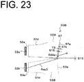
- FIG. 23 is a partial longitudinal cross-sectional view of the separator 50B.
- FIG. 24(a) is a perspective view of an upper separator body 52B, and
- FIG. 24(b) is a perspective view of a lower separator body 53B.
- the separator 50B shown in FIG. 23 is constituted by combining the upper separator body 52B and the lower separator body 53B shown in FIG. 24 .
- the separator 50B is different from the separator 50A of the above-described second embodiment in that, as shown in FIGS. 23 and 24(b) , the upper portion of the front end portion of the lower separator body 53B includes an overlap portion 57 extending upward. Except for this, the structure is the same as that of the separator 50A of the above-described second embodiment.
- differences from the separator 50A of the above-described second embodiment will be mainly described, and similar components are denoted by the same reference numerals and descriptions thereof will be omitted as appropriate.
- the overlap portion 57 is a thin-film light guide portion including a front surface 57a facing the upper light incident surface 60Ab1 of the primary lens 60A (not shown in FIG. 23 ), and a rear surface 57b facing the gap S13 between the lower portion (the front surface 52Aa) of the upper separator body 52B and the upper portion (the front surface 53a) of the lower separator body 53B and the front surface 52Aa of the upper separator body 52B.
- the thickness T3 of the overlap portion 57 is, for example, 0.2 mm. It should be noted that, in order to suppress the transmittance of light from the low-beam light sources 32a outputted through the front surface 52Aa of the upper separator body 52B from being reduced, it is desirable that the thickness T3 of the overlap portion 57 be as thin as possible.
- the overlap portion 57 is disposed with the gap S15 formed between the rear surface 57b of the overlap portion 57 and the front surface 52Aa of the upper separator body 52B so that the light Ray3 from the ADB light sources 32b guided within the overlap portion 57 while being repeatedly totally reflected between the front surface 57a and the rear surface 57b of the overlap portion 57 is outputted through the front surface 57a of the overlap portion 57.
- the gap S15 is, for example, 0.02 mm.
- a part of light for example, light Ray1 with a relatively strong luminous intensity (e.g., see FIG. 17 ) is directly outputted from the lower portion of the front surface 52Aa of the upper separator body 52B, passes through the overlap portion 57, further enters the primary lens 60A through the upper light incident surface 60Ab1 of the primary lens 60A, and is projected by the projection lens 90 constituted by the primary lens 60A and the secondary lens 80, to be used for forming the low-beam light distribution pattern.
- light Ray1 with a relatively strong luminous intensity e.g., see FIG. 17
- another part of light for example, light Ray2 with a relatively weak luminous intensity (e.g., see FIG. 17 ) is guided within the upper separator body 52B while being repeatedly totally reflected between the front surface 52Aa and the rear surface 52Ab of the upper separator body 52B to be outputted through the front surface 52Aa of the upper separator body 52B, passes through the overlap portion 57, further enters the primary lens 60A through the upper light incident surface 60Ab1 of the primary lens 60A, and is projected by the projection lens 90 constituted by the primary lens 60A and the secondary lens 80, to be used for forming the low-beam light distribution pattern.
- light Ray2 with a relatively weak luminous intensity e.g., see FIG. 17
- the light from the ADB light sources 32b enters the separator 50B (the second light guide portion 53d) through the second light incident surface 53e.
- the second light guide portion 53d Of the light from the ADB light sources 32b that has entered the separator 50B (the second light guide portion 53d), a part thereof is directly outputted from the upper portion of the front surface 53a of the lower separator body 53B, further enters the primary lens 60A through the lower light incident surface 60Ab2 of the primary lens 60A, and is projected by the projection lens 90 constituted by the primary lens 60A and the secondary lens 80, to be used for forming the ADB light distribution pattern.
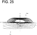
- the present inventors have confirmed that the composite light distribution pattern including the low-beam light distribution pattern and the ADB light distribution pattern formed as described above is configured such that the luminous intensity change between the low-beam light distribution pattern P Lo and the ADB light distribution pattern P ADB becomes smooth, as shown in FIG. 25 , so that it is possible to suppress the light distribution feeling from being reduced.
- FIG. 25 shows an example of a composite light distribution pattern including the low-beam light distribution pattern P Lo and the ADB light distribution pattern P ADB formed by the vehicle lighting fixture 10B.
- a vehicle lighting fixture 10B capable of smoothening the luminous intensity change between the low-beam light distribution pattern P Lo and the ADB light distribution pattern P ADB and suppressing the light distribution feeling from being reduced even when the gap S13 is generated between the front surface 52Aa of the upper separator body 52B, through which the light from the low-beam light sources 32a is outputted, and the front surface 53a of the lower separator body 53B, through which the light from the ADB light sources 32b is outputted.
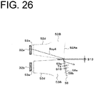
- FIG. 26 is a partial longitudinal cross-sectional view of the separator 50B (modified example).
- the overlap portion 57 in which the upper portion of the front end portion of the lower separator body 53B extends upward is used as the overlap portion, but the present invention is not limited thereto.
- an overlap portion 58 in which the lower portion of the front end portion of the upper separator body 52B extends downward may be used as the overlap portion.
- the overlap portion 58 is a thin-film light guide portion including a front surface 58a facing the lower light incident surface 60Ab2 (not shown in FIG. 26 ) of the primary lens 60A, and a rear surface 58b facing a gap S13 between the lower portion (the front surface 52Aa) of the upper separator body 52B and the upper portion (the front surface 53a) of the lower separator body 53B and the front surface 53a of the lower separator body 53B.
- the thickness T4 of the overlap portion 58 is, for example, 0.2 mm. It should be noted that, in order to suppress the transmittance of light from the ADB light sources 32b outputted through the front surface 53a of the lower separator body 53B from being reduced, it is desirable that the thickness T4 of the overlap portion 58 be as thin as possible.
- the overlap portion 58 is disposed with the gap S16 formed between the rear surface 58b of the overlap portion 58 and the front surface 53a of the lower separator body 53B so that the light from the low-beam light sources 32a guided within the overlap portion 58 while being repeatedly totally reflected between the front surface 58a and the rear surface 58b of the overlap portion 58 is outputted through the front surface 58a of the overlap portion 58.
- the gap S16 is, for example, 0.02 mm.
- light Ray1 with a relatively strong luminous intensity (e.g., see FIG. 17 ) is directly outputted from the lower portion of the front surface 52Aa of the upper separator body 52B, passes through the overlap portion 58, further enters the primary lens 60A through the upper light incident surface 60Ab1 of the primary lens 60A, and is projected by the projection lens 90 constituted by the primary lens 60A and the secondary lens 80, to be used for forming the low-beam light distribution pattern.
- light Ray2 with a relatively weak luminous intensity (e.g., see FIG. 17 ) is guided within the upper separator body 52B while being repeatedly totally reflected between the front surface 52Aa and the rear surface 52Ab of the upper separator body 52B to be outputted through the front surface 52Aa of the upper separator body 52B, further enters the primary lens 60A through the upper light incident surface 60Ab1 of the primary lens 60A, and is projected by the projection lens 90 constituted by the primary lens 60A and the secondary lens 80, to be used for forming the low-beam light distribution pattern.
- a relatively weak luminous intensity e.g., see FIG. 17
- the light from the low-beam light sources 32b that has entered the separator 50B (the first light guide portion 52d)
- another part thereof (refer to a light beam indicated by reference numeral Ray4 in FIG. 26 ) is guided within the overlap portion 58 while being repeatedly totally reflected between the front surface 58a and the rear surface 58b of the overlap portion 58 to be outputted through the front surface 58a of the overlap portion 58, and is further projected between the low-beam light distribution pattern (lower portion) and the ADB light distribution pattern (upper portion) by the projection lens 90 constituted by the primary lens 60A and the secondary lens 80.
- the light from the ADB light sources 32b enters the separator 50B (the second light guide portion 53d) through the second light incident surface 53e.
- the second light guide portion 53d Of the light from the ADB light sources 32b that has entered the separator 50B (the second light guide portion 53d), a part thereof is directly outputted from the upper portion of the front surface 53a of the lower separator body 53B, further enters the primary lens 60A through the lower light incident surface 60Ab2 of the primary lens 60A, and is projected by the projection lens 90 constituted by the primary lens 60A and the secondary lens 80, to be used for forming the ADB light distribution pattern.
- the present inventors have confirmed that the composite light distribution pattern including the low-beam light distribution pattern and the ADB light distribution pattern formed as described above is configured such that the luminous intensity change between the low-beam light distribution pattern P Lo and the ADB light distribution pattern P ADB becomes smooth, as shown in FIG. 25 , so that it is possible to suppress the light distribution feeling from being reduced.
- the overlap portion 57 is applied to the separator 50A of the vehicle lighting fixture 10A of the second embodiment, but the present invention is not limited thereto.
- the overlap portion 57 may be applied to the separator 50 of the vehicle lighting fixture 10A of the first embodiment and the other separators. The same applies to the overlap portion 58.
- the projection lens 90 constituted by two lenses i.e., the primary lens 60A and the secondary lens 80
- the present invention is not limited thereto.
- a projection lens constituted by a single lens or a projection lens constituted by three or more lenses may be used as the projection lens.
- separator 50A including the upper separator body 52A, the first light guide portion 52d, the lower separator body 53, and the second light guide portion 53d is used as the separator
- the present invention is not limited thereto.
- a separator including the upper separator body 52A and the first light guide portion 52d and not including the lower separator body 53 and the second light guide portion 53d may be used as the separator. That is, the lower separator body 53 and the second light guide portion 53d may be omitted.
- FIG. 21 is a modified example of the focal plane FP of the projection lens 90.
Landscapes
- Engineering & Computer Science (AREA)
- General Engineering & Computer Science (AREA)
- Physics & Mathematics (AREA)
- Microelectronics & Electronic Packaging (AREA)
- Optics & Photonics (AREA)
- Non-Portable Lighting Devices Or Systems Thereof (AREA)
Abstract
Description
- The present invention relates to a vehicle lighting fixture, and in particular, to a vehicle lighting fixture capable of preventing the luminous intensity at a portion (e.g., a portion around 4 degrees below the horizontal line) of a low-beam light distribution pattern from becoming relatively high, and also capable of forming a low-beam light distribution pattern with a uniform vertical thickness in a horizontal direction.
- Conventionally, there has been proposed a vehicle lighting fixture including a projection lens constituted by a first lens and a second lens, a light guide lens disposed behind the projection lens, and a low-beam light source that is disposed behind the light guide lens and emits light for forming a low-beam light distribution pattern by being irradiated forward through the light guide lens and the projection lens in this order (e.g., see Patent Literature 1 (
FIG. 1 , etc.)). - Patent Document 1: Japanese Patent Application Laid-Open No.
2015-79660 - However, the present inventors have studied the foregoing vehicle lighting fixture made in accordance with the conventional art described above, and found that although the vehicle lighting fixture satisfies the legal requirements for the low-beam light distribution pattern, the luminous intensity at a portion (e.g., a portion around 4 degrees below the horizontal line) of the low-beam light distribution pattern becomes relatively high to cause luminous intensity unevenness (luminance unevenness), and the thickness of the central portion of the low-beam light distribution pattern becomes smaller than those at both left and right ends, and as a result, the light distribution feeling is reduced.
- The present invention has been made in view of the foregoing circumstances, and an object thereof is to provide a vehicle lighting fixture capable of suppressing the luminous intensity at a portion (e.g., a portion around 4 degrees below the horizontal line) of the low-beam light distribution pattern from becoming relatively high, and also capable of forming a low-beam light distribution pattern with a uniform vertical thickness with respect to the horizontal direction (i.e., it is possible to suppress the light distribution feeling from being reduced).
- To achieve the foregoing object, an aspect of the present invention is a vehicle lighting fixture including a projection lens, a separator disposed behind the projection lens, and a low-beam light source that is disposed behind the separator and emits light for forming a low-beam light distribution pattern by being irradiated forward through the separator and the projection lens in this order. This vehicle lighting fixture is characterized in that: the separator includes an upper separator body that includes a front surface and a rear surface on the opposite side thereof, and a first light guide portion that extends from a lower portion of the upper separator body toward the low-beam light source and has a first light incident surface located at a tip end thereof and faces the low-beam light source; that the projection lens has a front surface and a rear surface on the opposite side thereof, and the rear surface of the projection lens has an upper light incident surface facing the front surface of the upper separate body; that the low-beam light source, the first light guide portion, the upper separator body, and the upper light incident surface are each disposed above a reference axis passing through the focal point of the projection lens and extending in a vehicle longitudinal direction; that the lower portion of the front surface of the upper separator body is in surface contact with the lower portion of the upper light incident surface of the rear surface of the projection lens; that a space is formed between a portion above the lower portion of the front surface of the upper separator body and a portion above the lower portion of the upper light incident surface of the rear surface of the projection lens; and that the light emitted from the low-beam light source enters the first light guide portion through the first light incident portion, and a part of the light is directly outputted from the front surface of the upper separator body, and another part of the light is guided within the upper separator body while being repeatedly totally reflected between the front surface and the rear surface of the upper separator body and then outputted through the front surface of the upper separator body and further enters the projection lens through the upper light incident surface of the projection lens to be projected by the projection lens, so that the light is used for forming the low-beam light distribution pattern.
- In the above-described invention, a preferable mode is characterized in that a distance between the front surface of the upper separator body and the upper light incident surface of the rear surface of the projection lens becomes wider upward.
- In the above-described invention, a preferable mode is characterized in that the surface shape of the upper light incident surface of the rear surface of the projection lens is adjusted in such a manner that the luminous intensity distribution of the low-beam light distribution pattern satisfies the legal requirements and the thickness of the low-beam light distribution pattern in the vertical direction is uniform with respect to the horizontal direction.
- Further, in the above-described invention, a preferable mode is characterized by further including an ADB light source that emits light that is irradiated forward while passing the separator and the projection lens in this order to form an ADB light distribution pattern, and in that the separator includes a lower separator body that includes a front surface and a rear surface on the opposite side thereof, and a second light guide portion that extends from an upper portion of the lower separator body toward the ADB light source and has a second light incident surface located at a tip end thereof and facing the ABD light source; that the rear surface of the projection lens further has a lower light incident surface facing the front surface of the lower separator body; that the ADB light source, the second light guide portion, the lower separator body, and the lower light incident surface are each disposed below the reference axis; and that the front surface of the lower separator body is in surface contact with the lower light incident surface of the rear surface of the projection lens.
-
-
FIG. 1 is a perspective view of avehicle lighting fixture 10. -
FIG. 2(a) is a top view of thevehicle lighting fixture 10, (b) is a front view thereof, and (c) is a side view thereof. -
FIG. 3 is a cross-sectional view of thevehicle lighting fixture 10 shown inFIG. 1 taken along a horizontal plane including a reference axis AX (a plane including the X-axis and Y-axis). -
FIG. 4 is a cross-sectional view of thevehicle lighting fixture 10 shown inFIG. 1 taken along a vertical plane including the reference axis AX (a plane including the X-axis and Z-axis). -
FIG. 5 is an exploded perspective view of thevehicle lighting fixture 10. -
FIG. 6 is a perspective view of a structure in which aheat sink 20, alight source module 30, aholder 40, and aseparator 50 are combined. -
FIG. 7 is a perspective view of theseparator 50. -
FIG. 8(a) is a partial front view of anupper separator body 52, (b) is a partial front view of alower separator body 53, and (c) is a front view (perspective view) of a plurality of low-beam light sources 32a and a plurality ofADB light sources 32b when seen through theseparator 50. -
FIG. 9(a) is a diagram showing an example of a low-beam light distribution pattern PLo, (b) is a diagram showing an example of an ADB light distribution pattern PADB, (c) is a diagram showing an example of a composite light distribution pattern including the low-beam light distribution pattern PLo and the ADB light distribution pattern PADB, and (d) is a diagram showing a state in which a plurality of regions (e.g., a plurality of regions A1 to A4 that are individually turned on and off) constituting the ADB light distribution pattern mutually overlap with one another while being formed in a circle. -
FIG. 10 is a diagram showing an example using a separator without anupper separator body 52 but with only a firstlight guide portion 52d (the same configuration as that of the light guide lens of the above-described conventional art). -
FIG. 11 is a diagram showing an example of a low-beam light distribution pattern PLo formed when using the separator without anupper separator body 52 but with only the firstlight guide portion 52d. -
FIG. 12 is a cross-sectional view of avehicle lighting fixture 10A taken along a vertical plane including the reference axis AX (plane including the X-axis and Z-axis). -
FIG. 13 is a cross-sectional view of thevehicle lighting fixture 10A shown inFIG. 12 taken along line A-A. -
FIG. 14 is a perspective view of aseparator 50A. -
FIG. 15(a) is a top view of theseparator 50A, (b) is a rear view thereof, (c) is a bottom view thereof, and (d) is a side view thereof. -
FIG. 16 is a diagram showing an example of a holding structure of theseparator 50A and aprimary lens 60A. -
FIG. 17 is a diagram for explaining optical paths of the light from the low-beam light source 32a. -
FIG. 18 is a diagram showing an example of a low-beam light distribution pattern PLo formed by thevehicle lighting fixture 10A. -
FIG. 19(a) is a diagram showing an example of an ADB light distribution pattern and a low-beam light distribution pattern formed when using the separator shown inFIG. 10 (the same light guide lens as that used in the above-described conventional art) and (b) is a diagram showing an example of an ADB light distribution pattern and a low-beam light distribution pattern formed when using the separator shown inFIG. 20 (the same light guide lens as that used in the above-described conventional art). -
FIG. 20 is a diagram for explaining the relationship between an upper light incident surface 60Ab1 and a lower light incident surface 60Ab2 of theprimary lens 60A and a focal plane FP of aprojection lens 90. -
FIG. 21 is a modified example of the focal plane FP of theprojection lens 90. -
FIG. 22(a) is a diagram for explaining a gap S13 between the front surface 52Aa of theupper separator body 52A and thefront surface 53a of thelower separator body 53 through which light from theADB light source 32b is outputted and (b) is a diagram showing an example of a composite light distribution pattern including a low-beam light distribution pattern and an ADB light distribution pattern when the gap S13 is formed. -
FIG. 23 is a partial longitudinal cross-sectional view of aseparator 50B. -
FIG. 24(a) is a perspective view of anupper separator body 52B and (b) is a perspective view of alower separator body 53B. -
FIG. 25 is a diagram showing an example of a composite light distribution pattern including a low-beam light distribution pattern PLo and an ADB light distribution pattern PADB formed by the vehicle lighting fixture 10B. -
FIG. 26 is a partial longitudinal cross-sectional view of theseparator 50B (modified example). -
FIG. 27 is a graph showing a luminous intensity distribution of light that has been guided through theupper separator body 52A while being repeatedly totally reflected between the front surface 52Aa and the rear surface 52Ab of theupper separator body 52A, so that the light is outputted from the front surface 52Aa of theupper separator body 52A. - Hereinafter, a
vehicle lighting fixture 10, which is an embodiment of the present invention, will be described with reference to the accompanying drawings. Corresponding components in the respective drawings are denoted by the same reference numerals, and a repetitive description thereof will be omitted. -
FIG. 1 is a perspective view of avehicle lighting fixture 10.FIG. 2(a) is a top view of thevehicle lighting fixture 10,FIG. 2(b) is a front view thereof, andFIG. 2(c) is a side view thereof. - The
vehicle lighting fixture 10 shown inFIGS. 1 and2 is a vehicle headlamp that is capable of forming a low-beam light distribution pattern PLo (seeFIG. 9(a) ) or a composite light distribution pattern including the low-beam light distribution pattern PLo and an ADB (Adaptive Driving Beam) light distribution pattern PADB (seeFIG. 9(c) ), and that is mounted on the left and right sides of a front end portion of a vehicle (not shown). The low-beam light distribution pattern PLo and the ADB light distribution pattern PADB are formed on a virtual vertical screen facing the vehicle front (disposed in front of the vehicle front about 25 m away therefrom). Incidentally, hereinafter, for convenience of description, XYZ axes are defined. The X-axis extends in the vehicle longitudinal direction, the Y-axis extends in the vehicle width direction, and the Z-axis extends in the vertical direction. -
FIG. 3 is a cross-sectional view of thevehicle lighting fixture 10 shown inFIG. 1 taken along a horizontal plane including a reference axis AX (a plane including the X-axis and Y-axis).FIG. 4 is a cross-sectional view of thevehicle lighting fixture 10 shown inFIG. 1 taken along a vertical plane including the reference axis AX (a plane including the X-axis and Z-axis).FIG. 5 is an exploded perspective view of thevehicle lighting fixture 10. - As shown in
FIGS. 3 to 5 , thevehicle lighting fixture 10 of the present embodiment includes aheat sink 20, alight source module 30, aholder 40, aseparator 50, aprimary lens 60, aretainer 70, asecondary lens 80, and the like. Thevehicle lighting fixture 10, although not shown, is disposed in a lamp chamber constituted by an outer lens and a housing, and is attached to the housing or the like. - As shown in
FIG. 5 , theheat sink 20 includes abase 22 made of aluminum die cast and including afront surface 22a and arear surface 22b on the opposite side. - The
front surface 22a includes a light source module mounting surface 22a1 and a peripheral surface 22a2 surrounding the light source module mounting surface 22a1. - The light source module mounting surface 22a1 and the peripheral surface 22a2 are each, for example, a plane parallel to a plane including the Y-axis and the Z-axis.
- Screw holes 22a5 are provided in the light source module mounting surface 22a1 (in
FIG. 5 , at three portions) in order to screw thelight source module 30. Further, positioning pins 22a6 are provided to the light source module mounting surface 22a1 (inFIG. 5 , at two portions) in order to position thelight source module 30,. - The peripheral surface 22a2 includes a holder abutment surface 22a3 against which the
holder 40 abuts, and a retainer abutment surface 22a4 against which theretainer 70 abuts. - The retainer abutment surface 22a4 is provided on each of the left and right sides of the peripheral surface 22a2.
- The thickness between the retainer abutment surface 22a4 and the
rear surface 22b (thickness in the X-axis direction) is thicker than the thickness between the holder abutment surface 22a3 and therear surface 22b (thickness in the X-axis direction), so as to constitute a step portion. - Screw
holes 22c, into which screw N1 is inserted, are provided in the base 22 (inFIG. 3 , at two portions). The screw holes 22c penetrate the base 22 from the retainer abutment surface 22a4 to therear surface 22b. -
First extension portions 24 are provided to the left and right sides of the base 22 to extend from the left and right sides of the base 22 rearward (X-axis direction). At the tip end portion of thefirst extension portion 24, asecond extension portion 26 extending sideward (Y-axis direction) is provided. -
Heat dissipation fins 28 are provided to therear surface 22b of thebase 22. - The
light source module 30 includes a plurality of low-beam light sources 32a and a plurality of ADBlight sources 32b, and asubstrate 34 on which the plurality of low-beam light sources 32a, the plurality of ADBlight sources 32b, and connectors 34c are mounted. -
FIG. 8(c) is a front view (perspective view) of the plurality of low-beam light sources 32a and the plurality of ADBlight sources 32b when seen through theseparator 50. - As shown in
FIG. 8(c) , the plurality of low-beam light sources 32a are mounted on thesubstrate 34 in a form in which they are arranged in the upper stage and along the Y-axis direction. The plurality of ADBlight sources 32b are mounted on thesubstrate 34 in a form in which they are arranged in the lower stage and along the Y-axis direction. - Each of the
light sources substrate 34 in a state in which the respective light emitting surface is directed forward (front). A plurality of rectangles inFIG. 8(c) represent the light emitting surfaces of therespective light sources - In the
substrate 34, there are provided throughholes 34a into which positioning pins 22a6 of theheat sink 20 are inserted (inFIG. 5 , at two portions) and notches S1 in which screws N2 are inserted (inFIG. 5 , at three portions). - A
light source module 30 with the above-described configuration is fixed to theheat sink 20 by screwing the screws N2 inserted into the notches S1 to the screw holes 22a5 of the heat sink 20 (the light source module mounting surface 22a1), while the positioning pins 22a6 of theheat sink 20 are inserted into the throughholes 34a of thesubstrate 34. - As shown in
FIGS. 3 to 5 , theholder 40 is made of a synthetic resin such as an acrylic resin or a polycarbonate resin, and includes a cup-shaped holdermain body 42 in which a front side is opened and a rear side is closed. - The
holder body 42 has afront surface 42a that is configured as a surface with the following shape (or a concave spherical surface to the rear). Thefront surface 42a is formed by inverting the rear surface of theseparator 50 so that the rear surface of the separator 50 (rear surface 52b of theupper separator body 52 and therear surface 53b of the lower separator body 53) is in surface contact with thefront surface 42a. - In the
holder body 42, a throughhole 42c in which the firstlight guide portion 52d and the secondlight guide portion 53d of theseparator 50 are inserted is provided. - To the
holder body 42 , acylindrical portion 44 extending toward the rear (X-axis direction) from the outer peripheral portion of theholder body 42 is provided. Then, at the tip end portion of thecylindrical portion 44, aflange portion 46 to abut against the holder abutment surface 22a3 of theheat sink 20 is provided. - In the holder main body 42 (and the cylindrical portion 44), a notch S4 is provided.
- On the front side
open end surface 40a of theholder 40, projectedportions 48 and projectedportions 49 are provided. -
FIG. 6 is a perspective view of a structure which has theheat sink 20, thelight source module 30, theholder 40, and theseparator 50 in combination. -
FIG. 7 is a perspective view of theseparator 50. - As shown in
FIG. 7 , theseparator 50 is a cup-shaped member made of a silicone resin and which has an open front side and a closed rear side. Theseparator 50 includes anupper separator body 52 and alower separator body 53. - As shown in
FIG. 4 , theupper separator body 52 is disposed above the reference axis AX, and thelower separator body 53 is disposed below the reference axis AX. The reference axis AX extends in the X-axis direction. - The
upper separator body 52 has afront surface 52a that is configured as a surface with a shape (concave spherical surface to the rear) that is formed by inverting the upper half of therear surface 60b of theprimary lens 60 so that the upper half, above the reference axis AX, of therear surface 60b of the primary lens 60 (convex spherical surface to the rear) is in surface contact with thefront surface 52a. - The
upper separator body 52 has arear surface 52b (seeFIGS. 3 and4 ) that is configured as a surface with a shape (convex spherical surface to the rear) that is formed by inverting the upper half of thefront surface 42a of the holder 40 (holder body 42) so that the upper half, above the reference axis AX, of thefront surface 42a (concave spherical surface to the front) of the holder 40 (holder body 42) is in surface contact with therear surface 52b. - As shown in
FIG. 8(a) , the lower edge of thefront surface 52a of theupper separator body 52 includes a stepped edge portion 52a1 with the shape corresponding to a cut-off line CLLo (CL1 to CL3) and extended edge portions 52a2 and 52a3 disposed on both sides of the stepped edge portion 52a1. The extended edge portion may be provided on only one side. - The stepped edge portion 52a1 includes a side e1 corresponding to the left horizontal cut-off line CL1, a side e2 corresponding to the right horizontal cut-off line CL2, and a side e3 corresponding to the oblique cut-off line CL3 connecting the left horizontal cut-off line CL1 and the right horizontal cut-off line CL2.
- The extended edge portion 52a2 is disposed at the same position as the side e1 with respect to the Z-axis direction. The extended edge portion 52a3 is disposed at the same position as the side e2 with respect to the Z-axis direction.
- The
upper separator body 52 has alower end surface 52c (seeFIG. 4 ). Thelower end surface 52c is a surface extending from the lower edge of thefront surface 52a of theupper separator body 52 toward therear surface 52b of theupper separator body 52 in the horizontal direction (X-axis direction). - As shown in
FIGS. 3 and4 , in order to guide the light from the light source module 30 (a plurality of low-beam light sources 32a), a firstlight guide portion 52d is provided to therear surface 52b of theupper separator body 52. The firstlight guide portion 52d has a proximal end portion that is provided in a partial region including the stepped edge portion 52a1 of therear surface 52b of theupper separator body 52, and extends toward the light source module 30 (the plurality of low-beam light sources 32a). It should be noted that the partial region including the stepped edge portion 52a1 is a region where the light source module 30 (the light emitting surfaces of the plurality of low-beam light sources 32a) faces therear surface 52b of theupper separator body 52. The firstlight guide portion 52d is inserted into the throughhole 42c of theholder 40. - A first
light incident surface 52e is provided at the tip end portion of the firstlight guide portion 52d. The firstlight incident surface 52e is, for example, a plane parallel to a plane including the Y-axis and the Z-axis. - The first
light incident surface 52e is disposed at a position where it faces the light source module 30 (the light emitting surfaces of the plurality of low-beam light sources 32a) (seeFIG. 4 ) in a state in which the firstlight guide portion 52d is inserted into the throughhole 42c of theholder 40. The distance between the firstlight incident surface 52e and the light source module 30 (the light emitting surfaces of the plurality of low-beam light sources 32a) is, for example, 0.2 mm. - As shown in
FIGS. 5 and7 , aflange portion 52f is provided to the front side open end surface of theupper separator body 52. Theflange portion 52f has a through hole 52f1 into which the projectedportion 48 of theholder 40 is inserted (inFIGS. 5 and7 , at one portion), and through holes 52f2 into which the projectedportions 49 of theholder 40 are inserted (inFIGS. 5 and7 , at two portions). - The
lower separator body 53 has afront surface 53a that is configured as a surface with a shape (concave spherical surface to the rear) that is formed by inverting the lower half of therear surface 60b of theprimary lens 60 so that the lower half, below the reference axis AX, of therear surface 60b of the primary lens 60 (convex spherical surface to the rear) is in surface contact with thefront surface 53a. - The
lower separator body 53 has arear surface 53b (seeFIGS. 3 and4 ) that is configured as a surface with a shape (convex spherical surface to the rear) that is formed by inverting the lower half of thefront surface 42a of the holder 40 (holder body 42) so that the lower half, below the reference axis AX, of thefront surface 42a (concave spherical surface to the front) of the holder 40 (holder body 42) is in surface contact with therear surface 53b. - As shown in
FIG. 8(b) , the upper edge of thefront surface 53a of thelower separator body 53 includes a stepped edge portion 53a1 (sides e1' to e3') with a shape obtained by inverting the stepped edge portion 52a1, and extended edge portions 53a2 and 53a3 disposed on both sides of the stepped edge portion 53a1. The extended edge portion may be provided on only one side. - The extended edge portion 53a2 is disposed at the same position as the side e1' with respect to the Z-axis direction. The extended edge portion 53a3 is disposed at the same position as the side e2' with respect to the Z-axis direction.
- The
lower separator body 53 has anupper end surface 53c (seeFIG. 4 ). Theupper end surface 53c is a surface extending from the upper edge of thefront surface 53a of thelower separator body 53 toward therear surface 53b of thelower separator body 53 in the horizontal direction (X-axis direction). - As shown in
FIGS. 3 and4 , in order to guide the light from the light source module 30 (a plurality of ADBlight sources 32b), a secondlight guide portion 53d is provided to therear surface 53b of thelower separator body 53. The secondlight guide portion 53d has a proximal end portion that is provided in a partial region including the stepped edge portion 53a1 of therear surface 53b of thelower separator body 53, and extends toward the light source module 30 (the plurality of ADBlight sources 32b). It should be noted that the partial region including the stepped edge portion 53a1 is a region where the light source module 30 (the light emitting surfaces of the plurality of ADBlight sources 32b) faces therear surface 53b of thelower separator body 53. The secondlight guide portion 53d is inserted into the throughhole 42c of theholder 40. - A second
light incident surface 53e is provided at the tip end portion of the secondlight guide portion 53d. The secondlight incident surface 53e is a surface adjusted such that a plurality of regions constituting the ADB light distribution pattern (e.g., a plurality of regions A1 to A4 which are individually turned on and off) are prevented from becoming circular and overlapping with each other as shown inFIG. 9(d) , and such that, as shown inFIG.9 (b) the regions are formed in a state of being divided by vertical edges.FIGS. 9(b) and 9(d) show an ADB light distribution pattern formed when four ADBlight sources 32b are provided. The hatched areas inFIGS. 9(b) and 9(d) indicate that the ADBlight sources 32b corresponding to the area are turned off. - The second
light incident surface 53e is disposed at a position where it faces the light source module 30 (the light emitting surfaces of the plurality of ADBlight sources 32b) (seeFIG. 4 ) in a state in which the secondlight guide portion 53d is inserted into the throughhole 42c of theholder 40. The distance between the secondlight incident surface 53e and the light source module 30 (the light emitting surfaces of the plurality of ADBlight sources 32b) is, for example, 0.2 mm. - As shown in
FIGS. 5 and7 , aflange portion 53f is provided to the front side open end surface of thelower separator body 53. Theflange portion 53f has through holes 53f1 into which the projectedportions 48 of theholder 40 are inserted (inFIGS. 5 and7 , at two portions). - It should be noted that the
lower separator body 53 has a notch S5 so that the connectors 34c of thelight source module 30 do not abut against (interfere with) thelower separator body 53. - As shown in
FIG. 8(c) , theupper separator body 52 and thelower separator body 53 constitute theseparator 50 in combination in a state in which the lower edge of thefront surface 52a of theupper separator body 52 and the upper edge of thefront surface 53a of thelower separator body 53 are in line contact with each other and thelower end surface 52c of theupper separator body 52 and theupper end surface 53c of thelower separator body 53 are in surface contact with each other. - The
separator 50 with the above-described configuration is disposed in such a manner that the firstlight guide portion 52d of theupper separator body 52 and the secondlight guide portion 53d of theupper separator body 52 are inserted into the throughholes 42c of the holder 40 (e.g., press-fit or fit), that the firstlight incident surface 52e of the upper separator body 52 (the firstlight guide portion 52d) and the light source module 30 (the light emitting surfaces of the plurality of low-beam light sources 32a) face each other and the secondlight incident surface 53e of the lower separator body 53 (the secondlight guide portion 53d) and the light source module 30 (the light emitting surfaces of the plurality of ADBlight sources 32b) face each other (seeFIGS. 3 and4 ), and that the rear surface of the separator 50 (therear surface 52b of theupper separator body 52 and therear surface 53b of the lower separator body 53) is in surface contact with thefront surface 42a of the holder 40 (holder body 42) (seeFIGS. 3 and4 ). - At that time, the projected
portions 48 of theholder 40 are inserted into the through hole 52f1 of theupper separator body 52 and the through holes 53f1 of the lower separator body 53 (seeFIG. 6 ). Furthermore, the projectedportions 49 of theholder 40 are also inserted into the through holes 52f2 of the upper separator body 52 (seeFIG. 6 ). - As shown in
FIG. 5 , theprimary lens 60 is a spherical lens that includes afront surface 60a and arear surface 60b on an opposite side thereof. Thefront surface 60a is a spherical surface convex to the front, and therear surface 60b is a spherical surface convex to the rear. Theprimary lens 60 includes aflange portion 62. Theflange portion 62 extends between thefront surface 60a and therear surface 60b so as to surround the reference axis AX. - As shown in
FIG. 5 , theretainer 70 includes aretainer body 72 that is made of a synthetic resin such as an acrylic resin or a polycarbonate resin and that includes a cylindrical body that widens in a conical shape from the front side open end surface toward the rear side open end surface. - As shown in
FIG. 5 , thesecondary lens 80 is made of a synthetic resin such as an acrylic resin or a polycarbonate resin, and includes alens body 82. - The
lens body 82 includes afront surface 82a and arear surface 82b on the opposite side thereto (seeFIGS. 3 and4 ). Thefront surface 82a is a plane parallel to the plane including the Y-axis and the Z-axis, and therear surface 82b is a convex spherical surface to the rear. - To the outer peripheral portion of the
lens body 82, acylindrical portion 84 extending from the outer peripheral portion of thelens body 82 toward the rear (X-axis direction) is provided. - The
primary lens 60 and thesecondary lens 80 constitute a projection lens with a focal point F (seeFIG. 8 (c) ) located in the vicinity of the lower edge (the stepped edge portion 52a1) of thefront surface 52a of theupper separator body 52 and the upper edge (the stepped edge portion 53a1) of thefront surface 53a of thelower separator body 53. The curvature of field of the projection lens (rear focal plane) substantially coincides with the lower edge (the stepped edge portion 52a1) of thefront surface 52a of theupper separator body 52 and the upper edge (the stepped edge portion 53a1) of thefront surface 53a of thelower separator body 53. - As the
primary lens 60 and thesecondary lens 80 constituting the projection lens, for example, a spherical lens and a plano-convex lens described in Japanese Patent Application Laid-Open No.2015-79660 - The
secondary lens 80 with the above-described configuration has thelens body 82 disposed in front of theprimary lens 60, and a pressing andscrew receiving portion 86 disposed in contact with theflange portion 76 of the retainer 70 (seeFIGS. 3 and4 ). - In the
vehicle lighting fixture 10 with the above-described configuration, when the plurality of low-beam light sources 32a are turned on, light from the plurality of low-beam light sources 32a is incident on the firstlight incident surface 52e of the firstlight guide portion 52d of theupper separator body 52, is guided within the firstlight guide portion 52d and is outputted from thefront surface 52a of theupper separator body 52. As a result, the luminous intensity distribution corresponding to the low-beam light distribution pattern is formed on thefront surface 52a of theupper separator body 52. The luminous intensity distribution includes the sides e1 to e3 (seeFIG. 8A ) corresponding to the cut-off line CLLo (CL1 to CL3). The projection lens, which is constituted by theprimary lens 60 and thesecondary lens 80, reverses and projects this luminous intensity distribution forward. Thus, as shown inFIG. 9(a) , this forms the low-beam light distribution pattern PLo including the cut-off line CL (CL1 to CL3) at the upper edge. - When the plurality of ADB
light sources 32b are turned on, light from the plurality of ADBlight sources 32b is incident on the secondlight incident surface 53e of the secondlight guide portion 53d of thelower separator body 53, is guided within the secondlight guide portion 53d, and is outputted from thefront surface 53a of thelower separator body 53. As a result, the luminous intensity distribution corresponding to the ADB light distribution pattern is formed on thefront surface 53a of thelower separator body 53. The luminous intensity distribution includes the sides e1' to e3' (seeFIG. 8(b) ) corresponding to the cut-offline CLADB (CL1' to CL3'. The projection lens, which is constituted by theprimary lens 60 and thesecondary lens 80, reverses and projects this luminous intensity distribution forward. Thus, as shown inFIG. 9(b) , this forms the ADB light distribution pattern PADB including the cut-offline CLADB (CL1' to CL3') at the lower edge.FIG. 9(b) shows the ADB light distribution patterns PADB formed when the number of the plurality of ADBlight sources 32b is four. The hatched area inFIG. 9(b) indicates that the ADBlight sources 32b corresponding to that area are turned off. - When the plurality of low-
beam light sources 32a and the plurality of ADBlight sources 32b are turned on, the composite light distribution pattern including the low-beam light distribution pattern PLo and the ADB light distribution pattern PADB is formed as shown inFIG. 9(c) . - The present inventors have studied and found that the
vehicle lighting fixture 10 with the above-described configuration, although satisfying the legal requirements for the low-beam light distribution pattern, forms the low-beam light distribution pattern with a portion (e.g., a portion around 4 degrees below the horizontal line) whose luminous intensity becomes relatively high, and, for example, causes luminous intensity unevenness (luminance unevenness), resulting in reducing the light distribution feeling. - The reason why the luminous intensity at a portion of the low-beam light distribution pattern (e.g., a portion around 4 degrees below the horizontal line) becomes high is that, of the light from the low-
beam light source 32a, light whose luminous intensity is relatively strong (e.g., light in a narrow angle direction with respect to an optical axis AX32a of the low-beam light source 32a (seeFIG. 4 )) is projected to a portion (e.g., a portion around 4 degrees below the horizontal line) of the low-beam light distribution pattern PLo by the projection lens constituted by theprimary lens 60 and thesecondary lens 80. -
FIG. 10 is a diagram showing an example using a separator without anupper separator body 52 but with only a firstlight guide portion 52d (the same light guide lens as that used in the above-described conventional art). - As shown in
FIG. 10 , when a separator without anupper separator body 52 but with only the firstlight guide portion 52d is used as theseparator 50, it has been found that the luminous intensity at a portion of the low-beam light distribution pattern PLo (e.g., a portion around 4 degrees below the horizontal line) becomes relatively high, and in addition, as shown inFIG. 11 , the thickness TC of the central portion of the low-beam light distribution pattern PLo becomes thin as compared with the thicknesses TL and TR of both left and right sides thereof, resulting in reduction in the light distribution feeling.FIG. 11 is a diagram showing an example of a low-beam light distribution pattern PLo formed when a separator without anupper separator body 52 but with only the firstlight guide portion 52d is used. - Although the detailed reason why the thickness TC of the central portion of the low-beam light distribution pattern PLo becomes thin as compared with the thicknesses TL and TR of both the left and right sides thereof is unknown, it can be considered as follows.
- That is, it is considered to be due to that, first, the thickness of the
upper separator body 52 along the reference axis AX with respect to the horizontal direction become thicker as it moves away from the reference axis AX (see thicknesses T1 and T2 inFIG. 3 ), and second, as the light from the low-beam light source 32a that transmits theupper separator body 52 through the thicker portion of theupper separator body 52, the optical path length within theupper separator body 52 becomes longer, and thus the light is outputted from thefront surface 52a of theupper separator body 52 while being greatly diffused in the vertical direction. - For example, of the
upper separator body 52, a portion farther from the reference axis AX (e.g., the portion with the thickness T2 inFIG. 3 ) is thicker than the portion closer to the reference axis AX (e.g., the portion with the thickness T1 inFIG. 3 ). Therefore, the light from the low-beam light source 32a that transmits theupper separator body 52 through a portion farther from the reference axis AX (e.g., a portion with the thickness T2 inFIG. 3 ) travels along a longer light path within theupper separator body 52 as compared with the light from the low-beam light source 32a that transmits a portion thereof near the reference axis AX (e.g., a portion with the thickness T1 inFIG. 3 ). As a result, it is considered that the thickness TC of the central portion of the low-beam light distribution pattern PLo is smaller than the thicknesses TL and TR of the left and right sides. - Further, the present inventors have studied this matter and found that: when the low-beam light distribution pattern is required to have a long length in the vertical direction, a lower density (narrow bright range), and a low maximum luminous intensity as compared with the ADB light distribution pattern, as shown in
FIG. 10 , if the focal plane FP of the projection lens 90 and the front surface 52a of the separator 50 through which light from the low-beam light source 32a is outputted (and the rear surface 60b of the primary lens 60 on which the light from the low-beam light source 32a outputted from the front surface 52a of the separator 50 is incident) are each spherical (a spherical surface of constant curvature) and coincide with each other (in surface contact with each other), and if the focal plane FP of the projection lens 90 and the front surface 53a of the separator 50 through which the light from the ADB light source 32b is outputted (and the rear surface 60b of the primary lens 60 on which the light from the ADB light source 32b outputted from the front surface 53a of the separator 50 is incident) are each spherical (a spherical surface of constant curvature) and coincide with each other (in surface contact with each other), the low-beam light distribution pattern PLo and the ADB light distribution pattern PADB have vertically symmetrical shapes and vertically symmetrical luminous intensity distributions as shown inFIG.19(a) , so that it is impossible to form the above-mentioned required low-beam light distribution pattern. It has also been found that the contour of the ADB light distribution pattern became clear and the light distribution feeling is reduced.FIG. 19(a) shows an example of an ADB light distribution pattern and a low-beam light distribution pattern formed when using the separator shown inFIG. 10 (the same light guide lens as that used in the above-described conventional art). - Next, as a second embodiment, a
vehicle lighting fixture 10A capable of preventing the luminous intensity at a portion (e.g., a portion around 4 degrees below the horizontal line) of the low-beam light distribution pattern from becoming relatively high, and also capable of forming a low-beam light distribution pattern with a uniform vertical thickness with respect to the horizontal direction (i.e., it is possible to suppress the light distribution feeling from being reduced) will be described. Note that "uniform" used in this specification is not limited to the meaning of the term uniform in a strict sense. That is, it is considered as being "uniform" as long as it can be visually evaluated as being uniform or substantially uniform. - The
vehicle lighting fixture 10A of the present embodiment is different from thevehicle lighting fixture 10 of the above-described first embodiment in that aseparator 50A is used instead of theseparator 50, and aprimary lens 60A is used instead of theprimary lens 60. Except for this, the configuration thereof is the same as that of the above-described first embodiment. Hereinafter, differences from the above-described first embodiment will be mainly described, and the same components are denoted by the same reference numerals, and descriptions thereof will be omitted as appropriate. -
FIG. 12 is a cross-sectional view of thevehicle lighting fixture 10A taken along a vertical plane including the reference axis AX (plane including the X-axis and Z-axis).FIG. 13 is a cross-sectional view of thevehicle lighting fixture 10A shown inFIG. 12 taken along line A-A. It should be noted that theheat sink 20, theholder 40, theretainer 70 and the like are not illustrated inFIGS. 12 and13 . - As shown in
FIGS. 12 and13 , thevehicle lighting fixture 10A includes thesecondary lens 80, aprimary lens 60A disposed behind thesecondary lens 80, aseparator 50A disposed behind theprimary lens 60A, a plurality of low-beam light sources 32a (hereinafter, which may be simply referred to as low-beam light source(s) 32a) that are disposed behind theseparator 50A and emit light for forming a low-beam light distribution pattern by being irradiated forward through theseparator 50A, theprimary lens 60A, and thesecondary lens 80 in this order, and a plurality of ADBlight sources 32b (hereinafter, which may be simply referred to as ADB light source(s) 32b) that emit light for forming an ADB light distribution pattern by being irradiated forward through theseparator 50A, theprimary lens 60A, and thesecondary lens 80 in this order. - As in the first embodiment, the low-
beam light sources 32a, the ADBlight sources 32b, theseparator 50A, theprimary lens 60A, and thesecondary lens 80 are held by theheat sink 20, theholder 40, theretainer 70 and the like to maintain the positional relationship shown inFIG. 12 . - The secondary lens 80 (the
front surface 82a and therear surface 82b) and theprimary lens 60A (thefront surface 60a) constitute aprojection lens 90. Specifically, theprojection lens 90 is constituted by, out of one or a plurality of lenses (in this embodiment, theprimary lens 60A and the secondary lens 80), the optical surface(s) (in this embodiment, thefront surface 60a of theprimary lens 60A and thefront surface 82a andrear surface 82b of the secondary lens 80) other than the rear surface of the rearmost lens (in this embodiment, the rear surface 60Ab of theprimary lens 60A). The focal plane FP of theprojection lens 90 is, for example, a spherical surface with a constant curvature (seeFIG. 20 ). - As shown in
FIG. 12 , the focal point F of theprojection lens 90 is located between the lower edge of the front surface 52Aa of theupper separator body 52A and the upper edge of thefront surface 53a of thelower separator body 53 in the vertical direction. Further, the focus F of theprojection lens 90, although not shown, is located at the center of the lower edge of the front surface 52Aa of theupper separator body 52A (and the upper edge of thefront surface 53a of the lower separator body 53) with respect to the horizontal direction. The reference axis AX passes through the focal point F, and extends in the vehicle longitudinal direction (X direction). -
FIG. 14 is a perspective view of theseparator 50A,FIG. 15(a) is a top view of theseparator 50A,FIG. 15(b) is a rear view thereof,FIG. 15(c) is a bottom view thereof, andFIG. 15(d) is a side view thereof. - The
separator 50A is made of a silicon resin, and is a cup-shaped member in which a front side is opened and a rear side is closed, as shown inFIG. 14 and the like. - As shown in
FIG. 12 , theseparator 50A includes anupper separator body 52A, a firstlight guide portion 52d, afirst extension portion 54, asecond extension portion 55, alower separator body 53, a secondlight guide portion 53d, and aflange portion 56, which are configured as a single part integrally molded. - The
upper separator body 52A is disposed above the reference axis AX, and thelower separator body 53 is disposed below the reference axis AX. - The
upper separator body 52A is a thin plate-shaped light guide portion including a front surface 52Aa and a rear surface 52Ab on the opposite side thereof. Specifically, theupper separator body 52A is a thin plate-shaped light guide portion, in a horizontal cross-section, curved along the rear surface 60Ab (the upper light incident surface 60Ab1) of theprimary lens 60A (seeFIG. 13 ), and, in a vertical cross-section, extending upward (seeFIG. 12 ). The lower edge of the front surface 52Aa of theupper separator body 52A includes a stepped edge portion 52a1 (not shown inFIG. 12 ) with a shape corresponding to the cut-off line CLLo (CL1 to CL3, as in the first embodiment described above. - As shown in
FIG. 12 and the like, theupper separator body 52A is disposed in a state in which the front surface 52Aa faces the rear surface 60Ab (the upper light incident surface 60Ab1) of theprimary lens 60A. - The lower portion of the front surface 52Aa of the
upper separator body 52A is in surface contact with the lower portion of the rear surface 60Ab (the upper light incident surface 60Ab1) of theprimary lens 60A. Further, a space S is formed between a portion above the lower portion of the front surface 52Aa of theupper separator body 52A and a portion above the lower portion of the rear surface 60Ab (the upper light incident surface 60Ab1) of theprimary lens 60A. - The distance (space S) between the front surface 52Aa of the
upper separator body 52A and the rear surface 60Ab (the upper light incident surface 60Ab1) of theprimary lens 60A increases upward. A relationship between the front surface 52Aa of theupper separator body 52A and the rear focal plane FP of the projection lens 90 (curvature of field. seeFIG. 12 ) is also the same. - Incidentally, since the light from the low-
beam light sources 32a outputted from the firstlight guide portion 52d of theupper separator body 52A (the front surface 52Aa) becomes diffused light, the light reaching the rear surface 60Ab (the upper light incident surface 60Ab1) of theprimary lens 60A weakens as the distance (space S) between the front surface 52Aa of theupper separator body 52A and the rear surface 60Ab (the upper light incident surface 60Ab1) of theprimary lens 60A becomes wider (i.e., upward from the reference axis AX). As a result, the low-beam light distribution pattern becomes an ideal luminous intensity distribution that decreases in a gradation manner from the upper edge downward. - The vertical length H1 (see
FIG. 12 ) of the portion (surface contact portion) where the lower portion of the front surface 52Aa of theupper separator body 52A and the lower portion of therear surface 60b (the upper light incident surface 60Ab1) of theprimary lens 60A are in surface contact with each other is, for example, 0.7 mm. The provision of the surface contact portion can form a high luminous intensity band with a relatively high luminous intensity in the vicinity of the cut-off line of the low-beam light distribution pattern. Further, the adjustment of the length H1 can adjust the vertical length of the high luminous intensity band. - The front surface 52Aa of the
upper separator body 52A is configured to be, for example, a slightly convex curved surface to the front such that the light from the low-beam light sources 32a to be guided through theupper separator body 52A while being repeatedly totally reflected between the front surface 52Aa and the rear surface 52Ab of theupper separator body 52A is outputted from the front surface 52Aa of theupper separator body 52A (seeFIG. 17 ). The rear surface 52Ab of theupper separator body 52A is also configured to be a slightly convex curved surface similarly to the front. - The thickness T of the
upper separator body 52A (seeFIG. 12 ) is, for example, 2 mm in consideration of moldability and the like. Further, the vertical length H2 of theupper separator body 52A (seeFIG. 12 ) is, for example, 7 mm in consideration of the vertical length (thickness) of the low-beam light distribution pattern. The adjustment of the length H2 can adjust the vertical length of the low-beam light distribution pattern. - As shown in
FIG. 12 , the firstlight guide portion 52d is a thin plate-shaped light guide portion including an upper surface 52d1 and a lower surface 52d2 on the opposite side thereof. The firstlight guide portion 52d extends from the lower portion of theupper separator body 52A (rear surface 52Ab) toward the low-beam light sources 32a, and has a firstlight incident surface 52e provided at the tip end thereof and facing the low-beam light sources 32a. The firstlight incident surface 52e is a surface through which the light from the low-beam light sources 32a enters theseparator 50A (the firstlight guide portion 52d), and is, for example, a plane parallel to a plane including the Y-axis and the Z-axis. - The
first extension portion 54 and thesecond extension portion 55 are so-called bridging portions for which no optical function is intended. Thefirst extension portion 54 extends from the upper end portion of theupper separator body 52A toward the front. Thesecond extension portion 55 extends from the front end portion of thefirst extension portion 54 along the rear surface 60Ab of theprimary lens 60A. - The
lower separator body 53 is a thin plate-shaped light guide portion including afront surface 53a and arear surface 53b on the opposite side thereof. The upper edge of thefront surface 53a of thelower separator body 53 includes a stepped edge portion 53a1 of the shape obtained by inverting the stepped edge portion 52a1, similarly to the above-described first embodiment (not shown inFIG. 12 ). - The second
light guide portion 53d extends from the upper portion of the lower separator body 53 (rear surface 53b) toward the ADBlight sources 32b and has a secondlight incident surface 53e provided at the tip end thereof and facing the ADBlight sources 32b. The secondlight incident surface 53e is a surface through which the light from the ADBlight sources 32b enters theseparator 50A (the secondlight guide portion 53d) and is, for example, a plane parallel to a plane including the Y-axis and Z-axis. -
FIG. 16 shows an example of a holding structure for theseparator 50A and theprimary lens 60A. - As shown in
FIG. 16 , theseparator 50A with the above-described configuration is interposed between theholder 40 and theretainer 70 together with theprimary lens 60A. Specifically, the firstlight guide portion 52d and the secondlight guide portion 53d are inserted into the throughholes 42c of theholder 40, and theseparator 50A is interposed between theholder 40 and theretainer 70 together with theprimary lens 60A in such a state that the firstlight incident surface 52e and the low-beam light sources 32a (the light emitting surfaces) face each other, the secondlight incident surface 53e and the ADBlight sources 32b (the light emitting surfaces) face each other, and the rear surface (the rear surfaces 52Ab and 53b, etc.) of theseparator 50A is in surface contact with thefront surface 42a of the holder 40 (the holder body 42). - The
primary lens 60A is made of a transparent resin such as an acrylic resin or a polycarbonate resin, and is a spherical lens including afront surface 60a and a rear surface 60Ab on the opposite side thereof as shown inFIG. 12 . Thefront surface 60a is a spherical surface convex to the front, and the rear surface 60Ab is a spherical surface convex to the rear. Theprimary lens 60A is provided with aflange portion 62, which extends so as to surround the reference axis AX between thefront surface 60a and the rear surface 60Ab. - The rear surface 60Ab of the
primary lens 60A includes an upper light incident surface 60Ab1 disposed above the reference axis AX and a lower light incident surface 60Ab2 disposed below the reference axis AX. - The upper light incident surface 60Ab1 is a surface through which light from the low-
beam light sources 32a outputted from the front surface 52Aa of theupper separator body 52A enters theprimary lens 60A. The upper light incident surface 60Ab1 is provided in a region of the rear surface 60Ab of theprimary lens 60A to which the front surface 52Aa of theupper separator body 52A faces. - The lower portion of the upper light incident surface 60Ab1 coincides with the rear focal plane FP of the
projection lens 90. On the other hand, the portion above the lower portion of the upper light incident surface 60Ab1 does not coincide with the rear focal plane FP of theprojection lens 90, but is inclined forward with respect to the rear focal plane FP. - The surface shape of the upper light incident surface 60Ab1 is adjusted in such a manner that it satisfies the legal requirements required for the low-beam light distribution pattern, luminous intensity at a portion (e.g., a portion around 4 degrees below the horizontal line) of the low-beam light distribution pattern can be suppressed from becoming relatively high, and the thickness of the pattern in the vertical direction becomes uniform with respect to the horizontal direction (i.e., it is possible to suppress the light distribution feeling from being reduced). For example, the surface shape of the upper light incident surface 60Ab1 is adjusted in such a manner that the luminous intensity distribution of the low-beam light distribution pattern decreases in a gradation manner from the upper edge of the low-beam light distribution pattern downward. It should be noted that in some cases, the surface shape of the front surface 52Aa of the
upper separator body 52A may be adjusted in the same manner. - Since the surface shape of the thus adjusted upper light incident surface 60Ab1 becomes a complex free curved surface, it is difficult to represent the surface shape of the upper light incident surface 60Ab1 by specific numerical values and the like.
- However, it is possible to find the surface shape of the upper light incident surface 60Ab1 that forms the low-beam light distribution pattern - that satisfies the legal requirements required for the low-beam light distribution pattern, is capable of suppressing luminous intensity at a portion (e.g., a portion around 4 degrees below the horizontal line) of the low-beam light distribution pattern from becoming relatively high, and uniforms the thickness of the pattern in the vertical direction with respect to the horizontal direction, (i.e., it is possible to suppress the light distribution feeling from being reduced) - by, for example, using a predetermined simulation software to adjust the surface shape of the upper light incident surface 60Ab1, and by, each time it is adjusted, confirming the low-beam light distribution pattern (luminous intensity distribution, etc.).
- The lower light incident surface 60Ab2 is a surface through which light from the ADB
light sources 32b outputted from thefront surface 53a of thelower separator body 53 enters theprimary lens 60A. The lower light incident surface 60Ab2 is provided in a region of the rear surface 60Ab of theprimary lens 60A to which thefront surface 53a of thelower separator body 53 faces. The lower light incident surface 60Ab2 coincides with the rear focal plane FP of theprojection lens 90. - As shown in
FIG. 16 , theprimary lens 60A with the above-described configuration is interposed between theholder 40 and theretainer 70 together with theseparator 50A. Specifically, theprimary lens 60A with the above-described configuration is interposed between theholder 40 and theretainer 70 together with theseparator 50A in such a state that theflange portion 62 is in contact with theflange portion 56 of theseparator 50A, a portion of the rear surface 60Ab is in surface contact with thesecond extension portion 55 of theseparator 50A, the lower portion of the rear surface 60Ab (the upper light incident surface 60Ab1) is in surface contact with the lower portion of the front surface 52Aa of theupper separator body 52A, the rear surface 60Ab (the lower light incident surface 60Ab2) is in surface contact with thefront surface 53a of thelower separator body 53, and a space S is formed between the front surface 52Aa of theupper separator body 52 and the rear surface 60Ab (the upper light incident surface 60Ab1) of theprimary lens 60A. -
FIG. 20 is a diagram for describing the relationship between the upper light incident surface 60Ab1 and the lower light incident surface 60Ab2 of theprimary lens 60A and the focal plane FP of theprojection lens 90. - As shown in
FIG. 20 , assume a case in which the lower portion of the upper light incident surface 60Ab1 of theprimary lens 60A and the upper portion of the lower light incident surface 60Ab2 of theprimary lens 60A are defined as a first region B1, a portion above the lower portion of the upper light incident surface 60Ab1 of theprimary lens 60A is defined as a second region B2, and a portion below the upper portion of the lower light incident surface 60Ab2 of theprimary lens 60A is defined as a third region B3. In this case, the first region B1 coincides with the focal plane FP of theprojection lens 90, the second region B2 is disposed forward with respect to the focal plane FP of the projection lens 90 (or rearward), and the third region B3 is disposed rearward with respect to the focal plane FP of the projection lens 90 (or forward). - The distance between the second region B2 and the focal plane FP of the
projection lens 90 becomes wider upward from the reference axis AX. On the other hand, the distance between the third region B3 and the focal plane FP of theprojection lens 90 becomes wider downward from the reference axis AX. - It should be noted that the adjustment of the first region B1 can adjust the vertical length of the relatively high luminous intensity band with a relative high luminous intensity near the cut-off line of the low-beam light distribution pattern and the vertical length of the relatively high luminous intensity band with a relative high luminous intensity near the lower edge of the ADB light distribution pattern. Further, the adjustment of the second region B2 can adjust the vertical length of the low-beam light distribution pattern. In addition, the adjustment of the third region B3 can adjust the vertical length of the ADB light distribution pattern.
- The
secondary lens 80 is made of a transparent resin such as an acrylic resin or a polycarbonate resin, and is a plano-convex lens including afront surface 82a and arear surface 82b on the opposite side thereof. Thefront surface 82a is a plane parallel to the plane including the Y-axis and Z-axis, and therear surface 82b is a convex spherical surface to the rear. -
FIG. 17 is a diagram for explaining an optical path of light from the low-beam light sources 32a. - In the
vehicle lighting fixture 10A with the above-described configuration, when the low-beam light sources 32a are turned on, light from the low-beam light sources 32a enters theseparator 50A (the firstlight guide portion 52d) through the firstlight incident surface 52e. - As shown in
FIG. 17 , of the light from the low-beam light sources 32a that has entered theseparator 50A (the firstlight guide portion 52d), a part of light, for example, light Ray1 with a relatively strong luminous intensity (e.g., light in the narrow angle direction with respect to the optical axis AX32a of the low-beam light sources 32a) is directly outputted from the lower portion of the front surface 52Aa of theupper separator body 52A, further enters theprimary lens 60A through the upper light incident surface 60Ab1 of theprimary lens 60A, and is projected by theprojection lens 90 constituted by theprimary lens 60A and thesecondary lens 80, to be used for forming the low-beam light distribution pattern. - Further, of the light from the low-
beam light source 32a that has entered theseparator 50A (the firstlight guide portion 52d), another part of light, for example, light Ray2 with a relatively weak luminous intensity (e.g., light in the wide angle direction with respect to the optical axis AX32a of the low-beam light sources 32a) is guided within theupper separator body 52A while being repeatedly totally reflected between the front surface 52Aa and the rear surface 52Ab of theupper separator body 52A to be outputted through the front surface 52Aa of theupper separator body 52A, further enters theprimary lens 60A through the upper light incident surface 60Ab1 of theprimary lens 60A, and is projected by theprojection lens 90 constituted by theprimary lens 60A and thesecondary lens 80, to be used for forming the low-beam light distribution pattern.FIG. 27 is a graph showing the luminous intensity distribution of light that is guided within theupper separator body 52A while being repeatedly totally reflected between the front surface 52Aa and the rear surface 52Ab of theupper separator body 52A to be outputted through the front surface 52Aa of theupper separator body 52A. - The present inventors have confirmed that the low-beam light distribution pattern formed as described above satisfies the legal requirements for the low-beam light distribution pattern, as shown in
FIG. 18 , the luminous intensity at a portion (e.g., a portion around 4 degrees below the horizontal line H) of the low-beam light distribution pattern can be suppressed from becoming relatively high, and the thickness of the pattern in the vertical direction with respect to the horizontal direction becomes uniform (i.e., thicknesses TC, TL, and TR become uniform, so that the light distribution feeling can be prevented from being reduced).FIG. 18 shows an example of a low-beam light distribution pattern PLo formed by thevehicle lighting fixture 10A. - Although the detailed reason why the luminous intensity at a portion (e.g., a portion around 4 degrees below the horizontal line) of the low-beam light distribution pattern is not high is unknown, it can be considered as follows.
- That is, since the space S is formed between the front surface 52Aa of the
upper separator body 52A and the rear surface 60Ab (the upper light incident surface 60Ab1) of theprimary lens 60A, the light Ray1 with the relatively strong luminous intensity out of the light from the low-beam light sources 32a that has entered theseparator 50A (the firstlight guide portion 52d) is refracted (diffused), and further, Fresnel reflected each time when it is outputted through the front surface 52Aa of theupper separator body 52A and when the light enters theprimary lens 60A through the rear surface 60Ab (the upper light incident surface 60Ab1) of theprimary lens 60A. As a result, it is considered that light travelling toward the portion (e.g., a portion around 4 degrees below the horizontal line) of the low-beam light distribution pattern is reduced. - The detailed reason why the vertical thickness is uniformly formed with respect to the horizontal direction is unknown, but the following can be considered.
- Specifically, it is considered that, since the space S is formed between the front surface 52Aa of the
upper separator body 52A and the rear surface 60Ab (the upper light incident surface 60Ab1) of theprimary lens 60A, the light Ray1 with the relatively strong luminous intensity out of the light from the low-beam light sources 32a that has entered theseparator 50A (the firstlight guide portion 52d) is refracted (diffused) when entering theprimary lens 60A through the rear surface 60Ab (the upper light incident surface 60Ab1) of theprimary lens 60A, and a part of the light is projected to a portion (mainly, the lower region of the central portion) with a relatively low luminous intensity in the low-beam light distribution pattern by theprojection lens 90 constituted by theprimary lens 60A and thesecondary lens 80. - Further, it is considered to be because the light from the low-
beam light sources 32a guided within theupper separator body 52A while being repeatedly totally reflected between the front surface 52Aa and the rear surface 52Ab of theupper separator body 52A and outputted from the front surface 52Aa of theupper separator body 52A is projected to a portion (mainly, the lower region of the central portion) with a relatively low luminous intensity in the low-beam light distribution pattern by theprojection lens 90 constituted by theprimary lens 60A and thesecondary lens 80. - In addition, the present inventors have confirmed that the low-beam light distribution pattern formed as described above has a longer vertical length (T3 < T4 in
FIG. 19(b) ), a lower density (narrower bright range), and a lower maximum luminous intensity than the ADB light distribution pattern PADB, as shown inFIG. 19(b). FIG. 19(b) shows an example of the ADB light distribution pattern and the low-beam light distribution pattern formed when theseparator 50A shown inFIG. 20 is used. - The reason why the low-beam light distribution pattern becomes long in the vertical direction as compared with the ADB light distribution pattern is considered that the second region B2 is arranged forward with respect to the focal plane FP of the projection lens 90 (or rearward), and thus the light from the low-
beam light sources 32a that has outputted from the front surface 52Aa of theupper separator body 52A and entered theprimary lens 60A through the upper light incident surface 60Ab1 of theprimary lens 60A is projected in a blurred state by theprojection lens 90 constituted by theprimary lens 60A and thesecondary lens 80. - Further, the reason why the low-beam light distribution pattern has a lower density (narrower bright range) and lower maximum luminous intensity, as compared with the ADB light distribution pattern, is the same reason as the reason why the luminous intensity at a portion (e.g., a portion around 4 degrees below the horizontal line) of the above-described low-beam light distribution pattern is not high.
- It should be noted that the reason why the width W2 of the low-beam light distribution pattern PLo is wider than the width W1 of the ADB light distribution pattern PADB in
FIG. 19 (b) is that, as shown inFIG. 15 (b) , the width W4 of the firstlight guide portion 52d through which the light from the low-beam light sources 32a is guided is wider than the width W3 of the secondlight guide portion 53d through which the light from the ADBlight source 32b is guided. - It should be noted that, when the ADB
light sources 32b are turned on, the ADB light distribution pattern PADB is formed, and when the low-beam light sources 32a and the ADBlight sources 32b are turned on, the composite light distribution pattern including the low-beam light distribution pattern PLo and the ADB light distribution pattern PADB is formed. This point of issue is the same as that of the first embodiment, and therefore the description thereof is omitted here. - In addition, the present inventors have confirmed that the contour of the ADB light distribution pattern formed as described above is formed in an appropriately blurred state.
- The reason why the contour of the ADB light distribution pattern is formed in an appropriately blurred state is considered that, since the third region B3 is disposed rearward with respect to the focal plane FP of the projection lens 90 (or frontward), the light from the ADB
light source 32b outputted from thefront surface 53a of thelower separator body 53 and further and entering theprimary lens 60A from the lower light incident surface 60Ab2 of theprimary lens 60A is projected in a blurred state by theprojection lens 90 constituted by theprimary lens 60A and thesecondary lens 80. - As described above, according to the present embodiment, there can be provided the
vehicle lighting fixture 10A capable of suppressing the luminous intensity at a portion (e.g., a portion around 4 degrees below the horizontal line) of the low-beam light distribution pattern from becoming relatively high, and capable of forming the low-beam light distribution pattern with a uniform thickness in the vertical direction with respect to the horizontal direction (i.e., capable of suppressing the light distribution feeling from being reduced). - Further, according to the present embodiment, there can be provided the
vehicle lighting fixture 10A capable of forming the low low-beam light distribution pattern with a longer length in the vertical direction, a lower density (narrow bright range), and a low maximum luminous intensity, as compared with the ADB light distribution pattern, and the ADB light distribution pattern whose contour is appropriately blurred. - The present inventors have studied and found that, in the
vehicle lighting fixture 10A with the above-described configuration, a gap S13 is generated in some cases between the front surface 52Aa of theupper separator body 52A, through which the light from the low-beam light sources 32a is outputted, and thefront surface 53a of thelower separator body 53, through which the light from the ADBlight sources 32b is outputted, as shown inFIG. 22(a) , due to the molding variation of theseparator 50A or temperature change, and that when the gap S13 is generated, as shown inFIG. 22(b) , the luminous intensity at an area between the low-beam light distribution pattern PLo and the ADB light distribution pattern PADB (see symbol S14 inFIG. 22(a) ) is abruptly reduced, so that the light distribution feeling is reduced.FIG. 22(a) is a diagram for explaining the gap S13 between the front surface 52Aa of theupper separator body 52A and thefront surface 53a of thelower separator body 53 through which the light from the ADBlight sources 32b is outputted, andFIG. 22(b) is a diagram showing an example of a composite light distribution pattern including the low-beam light distribution pattern and the ADB light distribution pattern when the gap S13 is formed. - Next, as a third embodiment, a description regarding a vehicle lighting fixture 10B will be described, which is capable of smoothening the luminous intensity change between the low-beam light distribution pattern PLo and the ADB light distribution pattern PADB and suppressing the light distribution feeling from being reduced, even when a gap S13 is generated between the front surface 52Aa of the
upper separator body 52A, through which the light from the low-beam light sources 32a is outputted, and thefront surface 53a of thelower separator body 53, through which the light from the ADBlight sources 32b is outputted. - The vehicle lighting fixture 10B of the present embodiment is different from the
vehicle lighting fixture 10A of the above-described second embodiment in that aseparator 50B is used instead of theseparator 50A. Except for this, the configuration is the same as that of the above-described second embodiment. Hereinafter, differences from the above-described second embodiment will be mainly described, and similar components are denoted by the same reference numerals, and descriptions thereof will be omitted as appropriate. -
FIG. 23 is a partial longitudinal cross-sectional view of theseparator 50B.FIG. 24(a) is a perspective view of anupper separator body 52B, andFIG. 24(b) is a perspective view of alower separator body 53B. - The
separator 50B shown inFIG. 23 is constituted by combining theupper separator body 52B and thelower separator body 53B shown inFIG. 24 . - The
separator 50B is different from theseparator 50A of the above-described second embodiment in that, as shown inFIGS. 23 and24(b) , the upper portion of the front end portion of thelower separator body 53B includes anoverlap portion 57 extending upward. Except for this, the structure is the same as that of theseparator 50A of the above-described second embodiment. Hereinafter, differences from theseparator 50A of the above-described second embodiment will be mainly described, and similar components are denoted by the same reference numerals and descriptions thereof will be omitted as appropriate. - As shown in
FIG. 23 , theoverlap portion 57 is a thin-film light guide portion including afront surface 57a facing the upper light incident surface 60Ab1 of theprimary lens 60A (not shown inFIG. 23 ), and arear surface 57b facing the gap S13 between the lower portion (the front surface 52Aa) of theupper separator body 52B and the upper portion (thefront surface 53a) of thelower separator body 53B and the front surface 52Aa of theupper separator body 52B. - The thickness T3 of the
overlap portion 57 is, for example, 0.2 mm. It should be noted that, in order to suppress the transmittance of light from the low-beam light sources 32a outputted through the front surface 52Aa of theupper separator body 52B from being reduced, it is desirable that the thickness T3 of theoverlap portion 57 be as thin as possible. - The
overlap portion 57 is disposed with the gap S15 formed between therear surface 57b of theoverlap portion 57 and the front surface 52Aa of theupper separator body 52B so that the light Ray3 from the ADBlight sources 32b guided within theoverlap portion 57 while being repeatedly totally reflected between thefront surface 57a and therear surface 57b of theoverlap portion 57 is outputted through thefront surface 57a of theoverlap portion 57. The gap S15 is, for example, 0.02 mm. - In the vehicle lighting fixture 10B with the above-described configuration, when the low-
beam light sources 32a and the ADBlight sources 32b are simultaneously turned on, light from the low-beam light sources 32a enters theseparator 50B (the firstlight guide portion 52d) through the firstlight incident surface 52e. - Of the light from the low-
beam light sources 32a that has entered theseparator 50B (the firstlight guide portion 52d), a part of light, for example, light Ray1 with a relatively strong luminous intensity (e.g., seeFIG. 17 ) is directly outputted from the lower portion of the front surface 52Aa of theupper separator body 52B, passes through theoverlap portion 57, further enters theprimary lens 60A through the upper light incident surface 60Ab1 of theprimary lens 60A, and is projected by theprojection lens 90 constituted by theprimary lens 60A and thesecondary lens 80, to be used for forming the low-beam light distribution pattern. - Further, of the light from the low-
beam light sources 32a which has entered theseparator 50B (the firstlight guide portion 52d), another part of light, for example, light Ray2 with a relatively weak luminous intensity (e.g., seeFIG. 17 ) is guided within theupper separator body 52B while being repeatedly totally reflected between the front surface 52Aa and the rear surface 52Ab of theupper separator body 52B to be outputted through the front surface 52Aa of theupper separator body 52B, passes through theoverlap portion 57, further enters theprimary lens 60A through the upper light incident surface 60Ab1 of theprimary lens 60A, and is projected by theprojection lens 90 constituted by theprimary lens 60A and thesecondary lens 80, to be used for forming the low-beam light distribution pattern. - On the other hand, the light from the ADB
light sources 32b enters theseparator 50B (the secondlight guide portion 53d) through the secondlight incident surface 53e. - Of the light from the ADB
light sources 32b that has entered theseparator 50B (the secondlight guide portion 53d), a part thereof is directly outputted from the upper portion of thefront surface 53a of thelower separator body 53B, further enters theprimary lens 60A through the lower light incident surface 60Ab2 of theprimary lens 60A, and is projected by theprojection lens 90 constituted by theprimary lens 60A and thesecondary lens 80, to be used for forming the ADB light distribution pattern. - As shown in
FIG. 23 , of the light from the ADBlight source 32b that has entered theseparator 50B (the secondlight guide portion 53d), another part thereof (refer to a light beam indicated by reference numeral Ray3 inFIG. 23 ) is guided within theoverlap portion 57 while being repeatedly totally reflected between thefront surface 57a and therear surface 57b of theoverlap portion 57 to be outputted through thefront surface 57a of theoverlap portion 57, and is further projected between the low-beam light distribution pattern (the lower portion) and the ADB light distribution pattern (upper portion) by theprojection lens 90 constituted by theprimary lens 60A and thesecondary lens 80. - The present inventors have confirmed that the composite light distribution pattern including the low-beam light distribution pattern and the ADB light distribution pattern formed as described above is configured such that the luminous intensity change between the low-beam light distribution pattern PLo and the ADB light distribution pattern PADB becomes smooth, as shown in
FIG. 25 , so that it is possible to suppress the light distribution feeling from being reduced.FIG. 25 shows an example of a composite light distribution pattern including the low-beam light distribution pattern PLo and the ADB light distribution pattern PADB formed by the vehicle lighting fixture 10B. - As described above, according to the present embodiment, there can be provided a vehicle lighting fixture 10B capable of smoothening the luminous intensity change between the low-beam light distribution pattern PLo and the ADB light distribution pattern PADB and suppressing the light distribution feeling from being reduced even when the gap S13 is generated between the front surface 52Aa of the
upper separator body 52B, through which the light from the low-beam light sources 32a is outputted, and thefront surface 53a of thelower separator body 53B, through which the light from the ADBlight sources 32b is outputted. - Next, a modified example will be described.
-
FIG. 26 is a partial longitudinal cross-sectional view of theseparator 50B (modified example). - In the third embodiment described above, an example has been described in which the
overlap portion 57 in which the upper portion of the front end portion of thelower separator body 53B extends upward is used as the overlap portion, but the present invention is not limited thereto. For example, as shown inFIG. 26 , anoverlap portion 58 in which the lower portion of the front end portion of theupper separator body 52B extends downward may be used as the overlap portion. - The
overlap portion 58 is a thin-film light guide portion including afront surface 58a facing the lower light incident surface 60Ab2 (not shown inFIG. 26 ) of theprimary lens 60A, and arear surface 58b facing a gap S13 between the lower portion (the front surface 52Aa) of theupper separator body 52B and the upper portion (thefront surface 53a) of thelower separator body 53B and thefront surface 53a of thelower separator body 53B. - The thickness T4 of the
overlap portion 58 is, for example, 0.2 mm. It should be noted that, in order to suppress the transmittance of light from the ADBlight sources 32b outputted through thefront surface 53a of thelower separator body 53B from being reduced, it is desirable that the thickness T4 of theoverlap portion 58 be as thin as possible. - The
overlap portion 58 is disposed with the gap S16 formed between therear surface 58b of theoverlap portion 58 and thefront surface 53a of thelower separator body 53B so that the light from the low-beam light sources 32a guided within theoverlap portion 58 while being repeatedly totally reflected between thefront surface 58a and therear surface 58b of theoverlap portion 58 is outputted through thefront surface 58a of theoverlap portion 58. The gap S16 is, for example, 0.02 mm. - In this modified example, when the low-
beam light sources 32a and the ADBlight sources 32b are simultaneously turned on, light from the low-beam light sources 32a enters theseparator 50B (the firstlight guide portion 52d) through the firstlight incident surface 52e. - Of the light from the low-
beam light sources 32a that has entered theseparator 50B (the firstlight guide portion 52d), light Ray1 with a relatively strong luminous intensity (e.g., seeFIG. 17 ) is directly outputted from the lower portion of the front surface 52Aa of theupper separator body 52B, passes through theoverlap portion 58, further enters theprimary lens 60A through the upper light incident surface 60Ab1 of theprimary lens 60A, and is projected by theprojection lens 90 constituted by theprimary lens 60A and thesecondary lens 80, to be used for forming the low-beam light distribution pattern. - Further, of the light from the low-
beam light sources 32a which has entered theseparator 50B (the firstlight guide portion 52d), light Ray2 with a relatively weak luminous intensity (e.g., seeFIG. 17 ) is guided within theupper separator body 52B while being repeatedly totally reflected between the front surface 52Aa and the rear surface 52Ab of theupper separator body 52B to be outputted through the front surface 52Aa of theupper separator body 52B, further enters theprimary lens 60A through the upper light incident surface 60Ab1 of theprimary lens 60A, and is projected by theprojection lens 90 constituted by theprimary lens 60A and thesecondary lens 80, to be used for forming the low-beam light distribution pattern. - Furthermore, of the light from the low-
beam light sources 32b that has entered theseparator 50B (the firstlight guide portion 52d), another part thereof (refer to a light beam indicated by reference numeral Ray4 inFIG. 26 ) is guided within theoverlap portion 58 while being repeatedly totally reflected between thefront surface 58a and therear surface 58b of theoverlap portion 58 to be outputted through thefront surface 58a of theoverlap portion 58, and is further projected between the low-beam light distribution pattern (lower portion) and the ADB light distribution pattern (upper portion) by theprojection lens 90 constituted by theprimary lens 60A and thesecondary lens 80. - On the other hand, the light from the ADB
light sources 32b enters theseparator 50B (the secondlight guide portion 53d) through the secondlight incident surface 53e. - Of the light from the ADB
light sources 32b that has entered theseparator 50B (the secondlight guide portion 53d), a part thereof is directly outputted from the upper portion of thefront surface 53a of thelower separator body 53B, further enters theprimary lens 60A through the lower light incident surface 60Ab2 of theprimary lens 60A, and is projected by theprojection lens 90 constituted by theprimary lens 60A and thesecondary lens 80, to be used for forming the ADB light distribution pattern. - The present inventors have confirmed that the composite light distribution pattern including the low-beam light distribution pattern and the ADB light distribution pattern formed as described above is configured such that the luminous intensity change between the low-beam light distribution pattern PLo and the ADB light distribution pattern PADB becomes smooth, as shown in
FIG. 25 , so that it is possible to suppress the light distribution feeling from being reduced. - In the above-described third embodiment, an example in which the
overlap portion 57 is applied to theseparator 50A of thevehicle lighting fixture 10A of the second embodiment has been described, but the present invention is not limited thereto. For example, theoverlap portion 57 may be applied to theseparator 50 of thevehicle lighting fixture 10A of the first embodiment and the other separators. The same applies to theoverlap portion 58. - In the above-described embodiment, an example has been described in which the
projection lens 90 constituted by two lenses, i.e., theprimary lens 60A and thesecondary lens 80, is used as the projection lens, but the present invention is not limited thereto. For example, although not shown, a projection lens constituted by a single lens or a projection lens constituted by three or more lenses may be used as the projection lens. - In the above-described embodiment, an example in which the
separator 50A including theupper separator body 52A, the firstlight guide portion 52d, thelower separator body 53, and the secondlight guide portion 53d is used as the separator has been described, but the present invention is not limited thereto. For example, similarly to the above-described conventional art, a separator including theupper separator body 52A and the firstlight guide portion 52d and not including thelower separator body 53 and the secondlight guide portion 53d may be used as the separator. That is, thelower separator body 53 and the secondlight guide portion 53d may be omitted. - In the above-described embodiment, an example in which a spherical surface that has a constant curvature (see
FIG. 20 ) is used as the focal plane FP of theprojection lens 90 has been described, but the present invention is not limited thereto. For example, as shown inFIG. 21 , as the focal plane FP of theprojection lens 90, a spherical surface whose curvature changes unevenly may be used.FIG. 21 is a modified example of the focal plane FP of theprojection lens 90. - All of the numerical values shown in the above-described respective embodiments are illustrative, and it is needless to say that appropriate numerical values different from those may be used.
- The above-described embodiments are merely illustrative in all respects. The present invention is not to be construed as being limited by the description of the above-described respective embodiments. The invention may be embodied in various other modes without departing from the spirit or principal characteristics thereof.
- 10 ... Vehicle lighting fixture, 20 ... Heat sink, 22 ... Base, 22a ... Front surface, 22a1 ... Light source module mounting surface, 22a2 ... Peripheral surface, 22a3 ... Holder abutment surface, 22a4 ... Retainer abutment surface, 22a5 ... Screw hole, 22a6 ... Positioning pin, 22b ... Rear surface, 22c ... Screw hole, 24 ... first extension portion, 26 second extension portion, 28 ... Heat dissipation fin, 30 ... Light source module, 32a ... Low-beam light source, 32b ... ADB light source, 34 ... Substrate, 34a ... Through hole, 34c ... Connector, 40 ... Holder, 40a ... Front side open end surface, 42 ... Holder body, 42a ... Front surface, 42c ... Through hole, 44 ... Cylindrical portion, 46 ... Flange portion, 48 ... Projected portion, 49 ... Projected portion, 50, 50A ... Separator, 52, 52A ... Upper separator portion, 52a, 52Aa ... Front surface, 52a1 ... Stepped edge portion, 52a2 ... Extended edge portion, 52a3 ... Extended edge portion, 52b, 52Ab ... Rear surface, 52c ... Lower end surface, 52d ... First light guide portion, 52e ... First light incident surface, 52f ... Flange portion, 52f1 ... Through hole, 52f2 ... Through hole, 52g ... Light guide portion, 52h ... Light incident surface , 53 ... Lower separator body, 53a ... Front surface, 53a1 ... Stepped edge portion, 53a2 ... Extended edge portion, 53a3 ... Extended edge portion, 53b ... Rear surface, 53c ... Upper end surface, 53d ... Second light guide portion, 53e ... Second light incident surface, 53f ... Flange portion, 53f1 ... Through hole, 53g ... Light guide portion, 53h ... Light incident surface, 60, 60A ... Primary lens, 60a ... Front surface, 60b, 60Ab ... Rear surface, 60Ab1 ... Upper light incident surface , 60Ab2 ... Lower light incident surface, 62 ... Flange portion, 70 ... Retainer, 72 ... Retainer body, 76 ... Flange portion, 80 ... Secondary lens, 82 ... Lens body, 82a ... Front surface, 82b ... Rear surface, 84 ... Cylindrical portion, 86 ... Pressing and screw receiving portion, 88 ... Positioning pin, AX ... Reference axis, CL ... Cut-off line, CL1 ... Left horizontal cut-off line, CL2 ... Right horizontal cut-off line, CL3 ... Cut-off line, CLADB ... Cut-off line, CLLo ... Cut-off line, F ... Focus, N1, N2 ... Screw, PADB ... ADB light distribution pattern, PLo ... Low-beam pattern
Claims (4)
- A vehicle lighting fixture comprising: a projection lens; a separator disposed behind the projection lens; and a low-beam light source that is disposed behind the separator and emits light for forming a low-beam light distribution pattern by being irradiated forward through the separator and the projection lens in this order, wherein
the separator includes an upper separator body that has a front surface and a rear surface on an opposite side thereof, and a first light guide portion that extends from a lower portion of the upper separator body toward the low-beam light source and has a first light incident surface located at a tip end thereof and faces the low-beam light source;
the projection lens has a front surface and a rear surface on an opposite side thereof, and the rear surface of the projection lens has an upper light incident surface facing the front surface of the upper separate body;
the low-beam light source, the first light guide portion, the upper separator body, and the upper light incident surface are each disposed above a reference axis passing through the focal point of the projection lens and extending in a vehicle longitudinal direction;
the lower portion of the front surface of the upper separator body is in surface contact with a lower portion of the upper light incident surface of the rear surface of the projection lens;
a space is formed between a portion above the lower portion of the front surface of the upper separator body and a portion above the lower portion of the upper light incident surface of the rear surface of the projection lens; and
the light emitted from the low-beam light source enters the first light guide portion through the first light incident portion, and a part of the light is directly outputted from the front surface of the upper separator body, and another part of the light is guided within the upper separator body while being repeatedly totally reflected between the front surface and the rear surface of the upper separator body and then outputted through the front surface of the upper separator body and further enters the projection lens through the upper light incident surface of the projection lens to be projected by the projection lens, so that the light is used for forming the low-beam light distribution pattern. - The vehicle lighting fixture according to claim 1, wherein a distance between the front surface of the upper separator body and the upper light incident surface of the rear surface of the projection lens becomes wider upward.
- The vehicle lighting fixture according to claim 1 or 2, wherein a surface shape of the upper light incident surface of the rear surface of the projection lens is adjusted in such a manner that a luminous intensity distribution of the low-beam light distribution pattern satisfies legal requirements and a thickness of the low-beam light distribution pattern in a vertical direction is uniform with respect to a horizontal direction.
- The vehicle lighting fixture according to any one of claims 1 to 3, further comprising an ADB light source that emits light that is irradiated forward while passing the separator and the projection lens in this order to form an ADB light distribution pattern, and wherein
the separator includes a lower separator body that has a front surface and a rear surface on an opposite side thereof, and a second light guide portion that extends from an upper portion of the lower separator body toward the ADB light source and has a second light incident surface located at a tip end thereof and facing the ABD light source;
the rear surface of the projection lens further has a lower light incident surface facing the front surface of the lower separator body;
the ADB light source, the second light guide portion, the lower separator body, and the lower light incident surface are each disposed below the reference axis; and
the front surface of the lower separator body is in surface contact with the lower light incident surface of the rear surface of the projection lens.
Applications Claiming Priority (2)
| Application Number | Priority Date | Filing Date | Title |
|---|---|---|---|
| JP2018118349A JP7051607B2 (en) | 2018-06-21 | 2018-06-21 | Vehicle lighting |
| PCT/JP2019/019271 WO2019244519A1 (en) | 2018-06-21 | 2019-05-15 | Vehicle lighting fixture |
Publications (3)
| Publication Number | Publication Date |
|---|---|
| EP3812651A1 true EP3812651A1 (en) | 2021-04-28 |
| EP3812651A4 EP3812651A4 (en) | 2022-03-09 |
| EP3812651B1 EP3812651B1 (en) | 2023-09-06 |
Family
ID=68983661
Family Applications (1)
| Application Number | Title | Priority Date | Filing Date |
|---|---|---|---|
| EP19821997.4A Active EP3812651B1 (en) | 2018-06-21 | 2019-05-15 | Vehicle lighting fixture |
Country Status (5)
| Country | Link |
|---|---|
| US (1) | US11293617B2 (en) |
| EP (1) | EP3812651B1 (en) |
| JP (1) | JP7051607B2 (en) |
| CN (1) | CN112292562B (en) |
| WO (1) | WO2019244519A1 (en) |
Families Citing this family (3)
| Publication number | Priority date | Publication date | Assignee | Title |
|---|---|---|---|---|
| JP7051607B2 (en) | 2018-06-21 | 2022-04-11 | スタンレー電気株式会社 | Vehicle lighting |
| JP7221319B2 (en) * | 2021-03-03 | 2023-02-13 | 本田技研工業株式会社 | headlight control system |
| KR20250092602A (en) * | 2023-12-15 | 2025-06-24 | 현대자동차주식회사 | Lamp having Decoupling type Multiple Housing and Vehicle thereof |
Family Cites Families (8)
| Publication number | Priority date | Publication date | Assignee | Title |
|---|---|---|---|---|
| JP6222557B2 (en) * | 2013-10-17 | 2017-11-01 | スタンレー電気株式会社 | Vehicle lighting |
| WO2016006138A1 (en) * | 2014-07-08 | 2016-01-14 | 三菱電機株式会社 | Headlight module and headlight device |
| JP2018083533A (en) * | 2016-11-24 | 2018-05-31 | スタンレー電気株式会社 | Vehicle lamp |
| JP2018106837A (en) * | 2016-12-22 | 2018-07-05 | スタンレー電気株式会社 | Vehicle lighting |
| JP2018106889A (en) | 2016-12-26 | 2018-07-05 | スタンレー電気株式会社 | Vehicular lighting tool |
| KR101907372B1 (en) * | 2017-04-26 | 2018-10-12 | 현대모비스 주식회사 | Head lamp apparatus |
| US10648633B2 (en) * | 2017-11-29 | 2020-05-12 | Toyota Motor Engineering & Manufacturing North America, Inc. | Lamp assemblies with multiple lighting functions sharing a cover lens |
| JP7051607B2 (en) | 2018-06-21 | 2022-04-11 | スタンレー電気株式会社 | Vehicle lighting |
-
2018
- 2018-06-21 JP JP2018118349A patent/JP7051607B2/en active Active
-
2019
- 2019-05-15 WO PCT/JP2019/019271 patent/WO2019244519A1/en not_active Ceased
- 2019-05-15 CN CN201980041407.XA patent/CN112292562B/en active Active
- 2019-05-15 EP EP19821997.4A patent/EP3812651B1/en active Active
- 2019-05-15 US US17/254,277 patent/US11293617B2/en active Active
Also Published As
| Publication number | Publication date |
|---|---|
| EP3812651A4 (en) | 2022-03-09 |
| US11293617B2 (en) | 2022-04-05 |
| WO2019244519A1 (en) | 2019-12-26 |
| CN112292562A (en) | 2021-01-29 |
| JP2019220402A (en) | 2019-12-26 |
| JP7051607B2 (en) | 2022-04-11 |
| US20210270440A1 (en) | 2021-09-02 |
| EP3812651B1 (en) | 2023-09-06 |
| CN112292562B (en) | 2023-04-25 |
Similar Documents
| Publication | Publication Date | Title |
|---|---|---|
| US10851959B2 (en) | Vehicle headlight | |
| CN110121616B (en) | Lens holding structure and vehicle lamp | |
| CN108351080B (en) | Vehicle lamps | |
| US20140211493A1 (en) | Vehicle lighting unit | |
| CN113544550A (en) | Optical unit | |
| EP3812651B1 (en) | Vehicle lighting fixture | |
| CN108224352B (en) | Lamp fitting | |
| US11873958B2 (en) | Headlight for vehicle | |
| JP6222557B2 (en) | Vehicle lighting | |
| EP3587904A1 (en) | Vehicular lamp fitting | |
| JP7046730B2 (en) | Vehicle lighting | |
| US12522128B2 (en) | Vehicle lamp | |
| WO2018117230A1 (en) | Vehicle lamp | |
| US10823364B2 (en) | Vehicular lamp | |
| JP7215656B2 (en) | LIGHT GUIDING LENS HOLDING STRUCTURE AND VEHICLE LAMP | |
| CN110114611A (en) | Vehicle Lamps | |
| JP2022053628A (en) | Lighting device | |
| JP7279932B2 (en) | vehicle lamp | |
| US20170038022A1 (en) | Lighting fixture |
Legal Events
| Date | Code | Title | Description |
|---|---|---|---|
| STAA | Information on the status of an ep patent application or granted ep patent |
Free format text: STATUS: THE INTERNATIONAL PUBLICATION HAS BEEN MADE |
|
| PUAI | Public reference made under article 153(3) epc to a published international application that has entered the european phase |
Free format text: ORIGINAL CODE: 0009012 |
|
| STAA | Information on the status of an ep patent application or granted ep patent |
Free format text: STATUS: REQUEST FOR EXAMINATION WAS MADE |
|
| 17P | Request for examination filed |
Effective date: 20210107 |
|
| AK | Designated contracting states |
Kind code of ref document: A1 Designated state(s): AL AT BE BG CH CY CZ DE DK EE ES FI FR GB GR HR HU IE IS IT LI LT LU LV MC MK MT NL NO PL PT RO RS SE SI SK SM TR |
|
| AX | Request for extension of the european patent |
Extension state: BA ME |
|
| DAV | Request for validation of the european patent (deleted) | ||
| DAX | Request for extension of the european patent (deleted) | ||
| A4 | Supplementary search report drawn up and despatched |
Effective date: 20220204 |
|
| RIC1 | Information provided on ipc code assigned before grant |
Ipc: F21Y 115/30 20160101ALI20220131BHEP Ipc: F21Y 115/10 20160101ALI20220131BHEP Ipc: F21W 102/155 20180101ALI20220131BHEP Ipc: F21S 45/47 20180101ALI20220131BHEP Ipc: F21S 41/663 20180101ALI20220131BHEP Ipc: F21S 41/29 20180101ALI20220131BHEP Ipc: F21S 41/255 20180101ALI20220131BHEP Ipc: F21S 41/24 20180101ALI20220131BHEP Ipc: F21S 41/19 20180101ALI20220131BHEP Ipc: F21S 41/16 20180101ALI20220131BHEP Ipc: F21S 41/151 20180101ALI20220131BHEP Ipc: F21S 41/143 20180101ALI20220131BHEP Ipc: F21S 41/20 20180101AFI20220131BHEP |
|
| GRAP | Despatch of communication of intention to grant a patent |
Free format text: ORIGINAL CODE: EPIDOSNIGR1 |
|
| STAA | Information on the status of an ep patent application or granted ep patent |
Free format text: STATUS: GRANT OF PATENT IS INTENDED |
|
| INTG | Intention to grant announced |
Effective date: 20230403 |
|
| GRAS | Grant fee paid |
Free format text: ORIGINAL CODE: EPIDOSNIGR3 |
|
| GRAA | (expected) grant |
Free format text: ORIGINAL CODE: 0009210 |
|
| STAA | Information on the status of an ep patent application or granted ep patent |
Free format text: STATUS: THE PATENT HAS BEEN GRANTED |
|
| AK | Designated contracting states |
Kind code of ref document: B1 Designated state(s): AL AT BE BG CH CY CZ DE DK EE ES FI FR GB GR HR HU IE IS IT LI LT LU LV MC MK MT NL NO PL PT RO RS SE SI SK SM TR |
|
| REG | Reference to a national code |
Ref country code: GB Ref legal event code: FG4D |
|
| REG | Reference to a national code |
Ref country code: CH Ref legal event code: EP |
|
| REG | Reference to a national code |
Ref country code: DE Ref legal event code: R096 Ref document number: 602019036996 Country of ref document: DE |
|
| REG | Reference to a national code |
Ref country code: IE Ref legal event code: FG4D |
|
| REG | Reference to a national code |
Ref country code: LT Ref legal event code: MG9D |
|
| REG | Reference to a national code |
Ref country code: NL Ref legal event code: MP Effective date: 20230906 |
|
| PG25 | Lapsed in a contracting state [announced via postgrant information from national office to epo] |
Ref country code: GR Free format text: LAPSE BECAUSE OF FAILURE TO SUBMIT A TRANSLATION OF THE DESCRIPTION OR TO PAY THE FEE WITHIN THE PRESCRIBED TIME-LIMIT Effective date: 20231207 |
|
| PG25 | Lapsed in a contracting state [announced via postgrant information from national office to epo] |
Ref country code: SE Free format text: LAPSE BECAUSE OF FAILURE TO SUBMIT A TRANSLATION OF THE DESCRIPTION OR TO PAY THE FEE WITHIN THE PRESCRIBED TIME-LIMIT Effective date: 20230906 Ref country code: RS Free format text: LAPSE BECAUSE OF FAILURE TO SUBMIT A TRANSLATION OF THE DESCRIPTION OR TO PAY THE FEE WITHIN THE PRESCRIBED TIME-LIMIT Effective date: 20230906 Ref country code: NO Free format text: LAPSE BECAUSE OF FAILURE TO SUBMIT A TRANSLATION OF THE DESCRIPTION OR TO PAY THE FEE WITHIN THE PRESCRIBED TIME-LIMIT Effective date: 20231206 Ref country code: LV Free format text: LAPSE BECAUSE OF FAILURE TO SUBMIT A TRANSLATION OF THE DESCRIPTION OR TO PAY THE FEE WITHIN THE PRESCRIBED TIME-LIMIT Effective date: 20230906 Ref country code: LT Free format text: LAPSE BECAUSE OF FAILURE TO SUBMIT A TRANSLATION OF THE DESCRIPTION OR TO PAY THE FEE WITHIN THE PRESCRIBED TIME-LIMIT Effective date: 20230906 Ref country code: HR Free format text: LAPSE BECAUSE OF FAILURE TO SUBMIT A TRANSLATION OF THE DESCRIPTION OR TO PAY THE FEE WITHIN THE PRESCRIBED TIME-LIMIT Effective date: 20230906 Ref country code: GR Free format text: LAPSE BECAUSE OF FAILURE TO SUBMIT A TRANSLATION OF THE DESCRIPTION OR TO PAY THE FEE WITHIN THE PRESCRIBED TIME-LIMIT Effective date: 20231207 Ref country code: FI Free format text: LAPSE BECAUSE OF FAILURE TO SUBMIT A TRANSLATION OF THE DESCRIPTION OR TO PAY THE FEE WITHIN THE PRESCRIBED TIME-LIMIT Effective date: 20230906 |
|
| REG | Reference to a national code |
Ref country code: AT Ref legal event code: MK05 Ref document number: 1608980 Country of ref document: AT Kind code of ref document: T Effective date: 20230906 |
|
| PG25 | Lapsed in a contracting state [announced via postgrant information from national office to epo] |
Ref country code: NL Free format text: LAPSE BECAUSE OF FAILURE TO SUBMIT A TRANSLATION OF THE DESCRIPTION OR TO PAY THE FEE WITHIN THE PRESCRIBED TIME-LIMIT Effective date: 20230906 |
|
| PG25 | Lapsed in a contracting state [announced via postgrant information from national office to epo] |
Ref country code: IS Free format text: LAPSE BECAUSE OF FAILURE TO SUBMIT A TRANSLATION OF THE DESCRIPTION OR TO PAY THE FEE WITHIN THE PRESCRIBED TIME-LIMIT Effective date: 20240106 |
|
| PG25 | Lapsed in a contracting state [announced via postgrant information from national office to epo] |
Ref country code: AT Free format text: LAPSE BECAUSE OF FAILURE TO SUBMIT A TRANSLATION OF THE DESCRIPTION OR TO PAY THE FEE WITHIN THE PRESCRIBED TIME-LIMIT Effective date: 20230906 |
|
| PG25 | Lapsed in a contracting state [announced via postgrant information from national office to epo] |
Ref country code: ES Free format text: LAPSE BECAUSE OF FAILURE TO SUBMIT A TRANSLATION OF THE DESCRIPTION OR TO PAY THE FEE WITHIN THE PRESCRIBED TIME-LIMIT Effective date: 20230906 |
|
| PG25 | Lapsed in a contracting state [announced via postgrant information from national office to epo] |
Ref country code: SM Free format text: LAPSE BECAUSE OF FAILURE TO SUBMIT A TRANSLATION OF THE DESCRIPTION OR TO PAY THE FEE WITHIN THE PRESCRIBED TIME-LIMIT Effective date: 20230906 Ref country code: RO Free format text: LAPSE BECAUSE OF FAILURE TO SUBMIT A TRANSLATION OF THE DESCRIPTION OR TO PAY THE FEE WITHIN THE PRESCRIBED TIME-LIMIT Effective date: 20230906 Ref country code: IS Free format text: LAPSE BECAUSE OF FAILURE TO SUBMIT A TRANSLATION OF THE DESCRIPTION OR TO PAY THE FEE WITHIN THE PRESCRIBED TIME-LIMIT Effective date: 20240106 Ref country code: ES Free format text: LAPSE BECAUSE OF FAILURE TO SUBMIT A TRANSLATION OF THE DESCRIPTION OR TO PAY THE FEE WITHIN THE PRESCRIBED TIME-LIMIT Effective date: 20230906 Ref country code: EE Free format text: LAPSE BECAUSE OF FAILURE TO SUBMIT A TRANSLATION OF THE DESCRIPTION OR TO PAY THE FEE WITHIN THE PRESCRIBED TIME-LIMIT Effective date: 20230906 Ref country code: CZ Free format text: LAPSE BECAUSE OF FAILURE TO SUBMIT A TRANSLATION OF THE DESCRIPTION OR TO PAY THE FEE WITHIN THE PRESCRIBED TIME-LIMIT Effective date: 20230906 Ref country code: AT Free format text: LAPSE BECAUSE OF FAILURE TO SUBMIT A TRANSLATION OF THE DESCRIPTION OR TO PAY THE FEE WITHIN THE PRESCRIBED TIME-LIMIT Effective date: 20230906 Ref country code: PT Free format text: LAPSE BECAUSE OF FAILURE TO SUBMIT A TRANSLATION OF THE DESCRIPTION OR TO PAY THE FEE WITHIN THE PRESCRIBED TIME-LIMIT Effective date: 20240108 Ref country code: SK Free format text: LAPSE BECAUSE OF FAILURE TO SUBMIT A TRANSLATION OF THE DESCRIPTION OR TO PAY THE FEE WITHIN THE PRESCRIBED TIME-LIMIT Effective date: 20230906 |
|
| PG25 | Lapsed in a contracting state [announced via postgrant information from national office to epo] |
Ref country code: PL Free format text: LAPSE BECAUSE OF FAILURE TO SUBMIT A TRANSLATION OF THE DESCRIPTION OR TO PAY THE FEE WITHIN THE PRESCRIBED TIME-LIMIT Effective date: 20230906 Ref country code: IT Free format text: LAPSE BECAUSE OF FAILURE TO SUBMIT A TRANSLATION OF THE DESCRIPTION OR TO PAY THE FEE WITHIN THE PRESCRIBED TIME-LIMIT Effective date: 20230906 |
|
| REG | Reference to a national code |
Ref country code: DE Ref legal event code: R097 Ref document number: 602019036996 Country of ref document: DE |
|
| PG25 | Lapsed in a contracting state [announced via postgrant information from national office to epo] |
Ref country code: DK Free format text: LAPSE BECAUSE OF FAILURE TO SUBMIT A TRANSLATION OF THE DESCRIPTION OR TO PAY THE FEE WITHIN THE PRESCRIBED TIME-LIMIT Effective date: 20230906 |
|
| PLBE | No opposition filed within time limit |
Free format text: ORIGINAL CODE: 0009261 |
|
| STAA | Information on the status of an ep patent application or granted ep patent |
Free format text: STATUS: NO OPPOSITION FILED WITHIN TIME LIMIT |
|
| PG25 | Lapsed in a contracting state [announced via postgrant information from national office to epo] |
Ref country code: DK Free format text: LAPSE BECAUSE OF FAILURE TO SUBMIT A TRANSLATION OF THE DESCRIPTION OR TO PAY THE FEE WITHIN THE PRESCRIBED TIME-LIMIT Effective date: 20230906 Ref country code: SI Free format text: LAPSE BECAUSE OF FAILURE TO SUBMIT A TRANSLATION OF THE DESCRIPTION OR TO PAY THE FEE WITHIN THE PRESCRIBED TIME-LIMIT Effective date: 20230906 |
|
| 26N | No opposition filed |
Effective date: 20240607 |
|
| PG25 | Lapsed in a contracting state [announced via postgrant information from national office to epo] |
Ref country code: BG Free format text: LAPSE BECAUSE OF FAILURE TO SUBMIT A TRANSLATION OF THE DESCRIPTION OR TO PAY THE FEE WITHIN THE PRESCRIBED TIME-LIMIT Effective date: 20230906 |
|
| PG25 | Lapsed in a contracting state [announced via postgrant information from national office to epo] |
Ref country code: BG Free format text: LAPSE BECAUSE OF FAILURE TO SUBMIT A TRANSLATION OF THE DESCRIPTION OR TO PAY THE FEE WITHIN THE PRESCRIBED TIME-LIMIT Effective date: 20230906 |
|
| REG | Reference to a national code |
Ref country code: CH Ref legal event code: PL |
|
| PG25 | Lapsed in a contracting state [announced via postgrant information from national office to epo] |
Ref country code: MC Free format text: LAPSE BECAUSE OF FAILURE TO SUBMIT A TRANSLATION OF THE DESCRIPTION OR TO PAY THE FEE WITHIN THE PRESCRIBED TIME-LIMIT Effective date: 20230906 |
|
| PG25 | Lapsed in a contracting state [announced via postgrant information from national office to epo] |
Ref country code: LU Free format text: LAPSE BECAUSE OF NON-PAYMENT OF DUE FEES Effective date: 20240515 |
|
| PG25 | Lapsed in a contracting state [announced via postgrant information from national office to epo] |
Ref country code: MC Free format text: LAPSE BECAUSE OF FAILURE TO SUBMIT A TRANSLATION OF THE DESCRIPTION OR TO PAY THE FEE WITHIN THE PRESCRIBED TIME-LIMIT Effective date: 20230906 Ref country code: LU Free format text: LAPSE BECAUSE OF NON-PAYMENT OF DUE FEES Effective date: 20240515 Ref country code: CH Free format text: LAPSE BECAUSE OF NON-PAYMENT OF DUE FEES Effective date: 20240531 |
|
| REG | Reference to a national code |
Ref country code: BE Ref legal event code: MM Effective date: 20240531 |
|
| PG25 | Lapsed in a contracting state [announced via postgrant information from national office to epo] |
Ref country code: IE Free format text: LAPSE BECAUSE OF NON-PAYMENT OF DUE FEES Effective date: 20240515 |
|
| PG25 | Lapsed in a contracting state [announced via postgrant information from national office to epo] |
Ref country code: BE Free format text: LAPSE BECAUSE OF NON-PAYMENT OF DUE FEES Effective date: 20240531 |
|
| PG25 | Lapsed in a contracting state [announced via postgrant information from national office to epo] |
Ref country code: CY Free format text: LAPSE BECAUSE OF FAILURE TO SUBMIT A TRANSLATION OF THE DESCRIPTION OR TO PAY THE FEE WITHIN THE PRESCRIBED TIME-LIMIT; INVALID AB INITIO Effective date: 20190515 |
|
| PG25 | Lapsed in a contracting state [announced via postgrant information from national office to epo] |
Ref country code: HU Free format text: LAPSE BECAUSE OF FAILURE TO SUBMIT A TRANSLATION OF THE DESCRIPTION OR TO PAY THE FEE WITHIN THE PRESCRIBED TIME-LIMIT; INVALID AB INITIO Effective date: 20190515 |
|
| PG25 | Lapsed in a contracting state [announced via postgrant information from national office to epo] |
Ref country code: TR Free format text: LAPSE BECAUSE OF FAILURE TO SUBMIT A TRANSLATION OF THE DESCRIPTION OR TO PAY THE FEE WITHIN THE PRESCRIBED TIME-LIMIT Effective date: 20230906 |
|
| PGFP | Annual fee paid to national office [announced via postgrant information from national office to epo] |
Ref country code: GB Payment date: 20260409 Year of fee payment: 8 |
|
| PGFP | Annual fee paid to national office [announced via postgrant information from national office to epo] |
Ref country code: DE Payment date: 20260402 Year of fee payment: 8 |
|
| PGFP | Annual fee paid to national office [announced via postgrant information from national office to epo] |
Ref country code: FR Payment date: 20260401 Year of fee payment: 8 |