EP3812621B1 - Engrenage, utilisation d'un engrenage et procédé pour un engrenage - Google Patents
Engrenage, utilisation d'un engrenage et procédé pour un engrenage Download PDFInfo
- Publication number
- EP3812621B1 EP3812621B1 EP20198068.7A EP20198068A EP3812621B1 EP 3812621 B1 EP3812621 B1 EP 3812621B1 EP 20198068 A EP20198068 A EP 20198068A EP 3812621 B1 EP3812621 B1 EP 3812621B1
- Authority
- EP
- European Patent Office
- Prior art keywords
- switching
- power
- shaft
- switching group
- gear mechanism
- Prior art date
- Legal status (The legal status is an assumption and is not a legal conclusion. Google has not performed a legal analysis and makes no representation as to the accuracy of the status listed.)
- Active
Links
- 230000005540 biological transmission Effects 0.000 title claims description 97
- 238000000034 method Methods 0.000 title claims description 7
- 239000000969 carrier Substances 0.000 claims description 5
- 230000008878 coupling Effects 0.000 claims description 4
- 238000010168 coupling process Methods 0.000 claims description 4
- 238000005859 coupling reaction Methods 0.000 claims description 4
- 239000011159 matrix material Substances 0.000 description 3
- 238000002485 combustion reaction Methods 0.000 description 1
- 230000009977 dual effect Effects 0.000 description 1
- 238000009434 installation Methods 0.000 description 1
- 230000010354 integration Effects 0.000 description 1
- 230000001360 synchronised effect Effects 0.000 description 1
- 230000007704 transition Effects 0.000 description 1
Images


Classifications
-
- F—MECHANICAL ENGINEERING; LIGHTING; HEATING; WEAPONS; BLASTING
- F16—ENGINEERING ELEMENTS AND UNITS; GENERAL MEASURES FOR PRODUCING AND MAINTAINING EFFECTIVE FUNCTIONING OF MACHINES OR INSTALLATIONS; THERMAL INSULATION IN GENERAL
- F16H—GEARING
- F16H37/00—Combinations of mechanical gearings, not provided for in groups F16H1/00 - F16H35/00
- F16H37/02—Combinations of mechanical gearings, not provided for in groups F16H1/00 - F16H35/00 comprising essentially only toothed or friction gearings
- F16H37/06—Combinations of mechanical gearings, not provided for in groups F16H1/00 - F16H35/00 comprising essentially only toothed or friction gearings with a plurality of driving or driven shafts; with arrangements for dividing torque between two or more intermediate shafts
- F16H37/08—Combinations of mechanical gearings, not provided for in groups F16H1/00 - F16H35/00 comprising essentially only toothed or friction gearings with a plurality of driving or driven shafts; with arrangements for dividing torque between two or more intermediate shafts with differential gearing
- F16H37/0833—Combinations of mechanical gearings, not provided for in groups F16H1/00 - F16H35/00 comprising essentially only toothed or friction gearings with a plurality of driving or driven shafts; with arrangements for dividing torque between two or more intermediate shafts with differential gearing with arrangements for dividing torque between two or more intermediate shafts, i.e. with two or more internal power paths
-
- F—MECHANICAL ENGINEERING; LIGHTING; HEATING; WEAPONS; BLASTING
- F16—ENGINEERING ELEMENTS AND UNITS; GENERAL MEASURES FOR PRODUCING AND MAINTAINING EFFECTIVE FUNCTIONING OF MACHINES OR INSTALLATIONS; THERMAL INSULATION IN GENERAL
- F16H—GEARING
- F16H37/00—Combinations of mechanical gearings, not provided for in groups F16H1/00 - F16H35/00
- F16H37/02—Combinations of mechanical gearings, not provided for in groups F16H1/00 - F16H35/00 comprising essentially only toothed or friction gearings
- F16H37/04—Combinations of toothed gearings only
- F16H37/042—Combinations of toothed gearings only change gear transmissions in group arrangement
- F16H37/046—Combinations of toothed gearings only change gear transmissions in group arrangement with an additional planetary gear train, e.g. creep gear, overdrive
-
- F—MECHANICAL ENGINEERING; LIGHTING; HEATING; WEAPONS; BLASTING
- F16—ENGINEERING ELEMENTS AND UNITS; GENERAL MEASURES FOR PRODUCING AND MAINTAINING EFFECTIVE FUNCTIONING OF MACHINES OR INSTALLATIONS; THERMAL INSULATION IN GENERAL
- F16H—GEARING
- F16H37/00—Combinations of mechanical gearings, not provided for in groups F16H1/00 - F16H35/00
- F16H37/02—Combinations of mechanical gearings, not provided for in groups F16H1/00 - F16H35/00 comprising essentially only toothed or friction gearings
- F16H37/04—Combinations of toothed gearings only
- F16H37/042—Combinations of toothed gearings only change gear transmissions in group arrangement
-
- B—PERFORMING OPERATIONS; TRANSPORTING
- B60—VEHICLES IN GENERAL
- B60Y—INDEXING SCHEME RELATING TO ASPECTS CROSS-CUTTING VEHICLE TECHNOLOGY
- B60Y2200/00—Type of vehicle
- B60Y2200/20—Off-Road Vehicles
- B60Y2200/22—Agricultural vehicles
- B60Y2200/221—Tractors
-
- F—MECHANICAL ENGINEERING; LIGHTING; HEATING; WEAPONS; BLASTING
- F16—ENGINEERING ELEMENTS AND UNITS; GENERAL MEASURES FOR PRODUCING AND MAINTAINING EFFECTIVE FUNCTIONING OF MACHINES OR INSTALLATIONS; THERMAL INSULATION IN GENERAL
- F16H—GEARING
- F16H37/00—Combinations of mechanical gearings, not provided for in groups F16H1/00 - F16H35/00
- F16H37/02—Combinations of mechanical gearings, not provided for in groups F16H1/00 - F16H35/00 comprising essentially only toothed or friction gearings
- F16H37/04—Combinations of toothed gearings only
- F16H2037/049—Forward-reverse units with forward and reverse gears for achieving multiple forward and reverse gears, e.g. for working machines
-
- F—MECHANICAL ENGINEERING; LIGHTING; HEATING; WEAPONS; BLASTING
- F16—ENGINEERING ELEMENTS AND UNITS; GENERAL MEASURES FOR PRODUCING AND MAINTAINING EFFECTIVE FUNCTIONING OF MACHINES OR INSTALLATIONS; THERMAL INSULATION IN GENERAL
- F16H—GEARING
- F16H2200/00—Transmissions for multiple ratios
- F16H2200/003—Transmissions for multiple ratios characterised by the number of forward speeds
- F16H2200/0078—Transmissions for multiple ratios characterised by the number of forward speeds the gear ratio comprising twelve or more forward speeds
-
- F—MECHANICAL ENGINEERING; LIGHTING; HEATING; WEAPONS; BLASTING
- F16—ENGINEERING ELEMENTS AND UNITS; GENERAL MEASURES FOR PRODUCING AND MAINTAINING EFFECTIVE FUNCTIONING OF MACHINES OR INSTALLATIONS; THERMAL INSULATION IN GENERAL
- F16H—GEARING
- F16H2200/00—Transmissions for multiple ratios
- F16H2200/20—Transmissions using gears with orbital motion
- F16H2200/2002—Transmissions using gears with orbital motion characterised by the number of sets of orbital gears
- F16H2200/2007—Transmissions using gears with orbital motion characterised by the number of sets of orbital gears with two sets of orbital gears
Definitions
- the invention relates to a transmission with at least a first and a second shaft, with at least a first and a second shift group being arranged between the first and the second shaft, with each of the shift groups having at least two individually switchable transmission units for transmitting a torque, which differ in terms of differ from each other in terms of their transmission ratio.
- Transmissions of this type are usually used as so-called power shift transmissions in agricultural machines and are used to transmit mechanical power from a drive motor to a drive train of the corresponding vehicle. It is crucial here that the gears are designed in such a way that on the one hand a large spread is guaranteed and at the same time the mass inertia to be synchronized is as low as possible. For this reason, such transmissions usually have a large number of gears in order to be able to bridge the large spread.
- These individual gears are realized by shifting the two groupsets to one another, with the first group usually also being referred to as a gear group and the second group being referred to as a range group. If at least both groupsets have at least two transmission units, a total of four gears can be realized, with the minimum number of gears resulting from the product of the number of two groupsets.
- EP3109509 discloses a transmission which, according to the Examining Division of the European Patent Office, falls within the wording of the preamble of claim 1.
- DE102014226469A1 describes an epicyclic gear with several output shafts.
- DE102011084037A1 shows a motor vehicle transmission with a planetary gear to couple two pairs of gears together.
- a gear is always understood to mean a combination of activated transmission units of the first and second gear groups, which together produce a specific transmission ratio between the first and second shaft.
- the present invention is based on the object of specifying a transmission which, compared to the transmissions known hitherto, is distinguished by a large number of gears and, at the same time, a small number of clutches.
- the first switching group can be brought into operative connection via a planetary stage with the first shaft, the planetary group being designed in such a way that mechanical power introduced via the first shaft is transmitted via a first and/or about a second power path that can be coupled or uncoupled can be transmitted to the second wave, with each power path being assigned at least one transmission unit of the first switching group and wherein in at least one switching state of the first switching group the power flow runs via at least one transmission unit of the first and second power path.
- the first switching group is designed in such a way that the power can be transmitted not just via just one, but via at least two power paths, with the power being transmitted correspondingly via an associated transmission unit in each case.
- Pairs of gears for example, can be used as the transmission unit, with the transmission ratio of such a pair of gears being obtained from the difference in diameter of the individual gears relative to one another.
- the gears of these pairs of gears are also referred to as the drive gear and the driven gear, with a torque being transmitted from the drive gear to the driven gear.
- a transmission ratio can of course also be realized with a gear pair.
- the first switching group has at least two outer shaft sections that coaxially surround the first shaft, with at least one of the transmission units being arranged on one of the outer shaft sections and with a first outer shaft section being assigned to the first power path and a second outer shaft section being assigned to the second power path. Accordingly, at least two transmission units are arranged on two external shaft sections that can be rotated independently of one another. This makes it possible for both power paths to be switched on at the same time, since the rotational speed of both outer shaft sections can be decoupled from one another.
- the planetary stage preferably has a power input and at least two power outputs, which are each connected to one of the power paths, with a planetary clutch being arranged between the two power outputs of the planetary stage, which in a coupled state connects the two Power outputs directly to each other connects.
- Planetary stages usually have a large number of gears rotating around one another, which can serve either as a power input or as a power output.
- the gears can be equipped as sun gears, planetary gears and ring gears, with ring gears in particular not being a mandatory part of such a planetary gear set.
- the sun gear is located in the center of the planetary stage and is revolved by the planet gears, with the planet gears being connected to one another via a planet carrier. Accordingly, the sun gear, the planet carrier and also the ring gear can serve as a power input or as a power output.
- a connection is made to the corresponding shaft, with two power outputs of the planetary stage being or can be connected to an outer shaft section within the scope of the invention, and the power input being connected to the first shaft directly or with the involvement of an additional transmission unit.
- This additional transmission unit can be used, for example, to implement a reduction or a translation.
- a preferred embodiment of the planetary stage provides at least two sun gears arranged next to one another and two planetary gear sets arranged next to one another, each planetary gear set consisting of a planet carrier and individual planet gears.
- the planetary carriers are coupled directly to one another and are also connected to one of the outer shaft sections as a first power output.
- the second power output is realized via a sun gear which is correspondingly connected to the other outer shaft section.
- the other sun wheel serves as the power input, so that one sun wheel is provided as the power input and one sun wheel as the power output.
- the two sun gears and planetary gear sets arranged next to one another are also preferably designed in such a way that they differ from one another in terms of their transmission ratio.
- the sun wheel in the power input is preferably made larger than in the power output and the planet wheels in the power input are made correspondingly smaller than in the power output.
- both power outputs and thus both outer shaft sections have the same speed. Accordingly, a coupling only takes place if only one transmission unit is switched on or if the power is only to be transmitted via one power path. If a transmission unit is to be coupled in each of the two power paths, the planetary clutch must be decoupled so that the two speeds of the outer shaft sections or in the two power paths are independent of one another.
- the planetary clutch is designed as a disk clutch with an inner and an outer disk carrier, the disk carriers being connected to one of the power outputs of the planetary stage and one of the power paths, in particular to one of the outer shaft sections.
- the outer disk carrier is preferably connected to the planetary carrier of the planetary stage and the inner disk carrier is connected to the sun gear of the planetary stage, which acts as a power output.
- Each transmission unit of the first switching group is also preferably assigned a clutch, which is also preferably designed as a multi-plate clutch and via which the transmission unit can be coupled or decoupled.
- a clutch in particular a multi-plate clutch, is also preferably provided between the first shaft and the power input of the planetary stage.
- This has the advantage that a reversing unit can be arranged between the first shaft and the planetary stage in a simple manner, which is also designed to be coupled and which causes a reversal of the direction of rotation of the planetary stage when coupled.
- the clutch between the first shaft and the power input of the planetary stage is released, preferably also the power input, z. B. on the sun gear of the planetary stage, is connected to an outer shaft portion which encloses the first shaft coaxially.
- this outer shaft section is not only connected to the clutch, which brings about a connection between the first shaft and the power input, but also a reversing transmission unit, which is part of the reversing unit and causes a reversal of the direction of rotation.
- This reversing transmission unit can be designed, for example, in the form of a three-part gear set and can accordingly have a reversing clutch, e.g. B. a multi-plate clutch, to be connected or decoupled. Accordingly, this reversing clutch is only actuated when a reversal of the direction of rotation is required, the clutch between the first shaft and the power input or the outer shaft section of the first power input then being decoupled at the same time.
- the reversing unit is arranged in front of the planetary stage and thus also in front of the two switching groups, so that even when the direction of rotation is reversed, e.g. B. when reversing the full number gears is available and thus the gear spread is filled as completely as possible even in reverse operation.
- a third shaft is arranged between the first and the second shaft, with the second shift group being arranged between the second and the third shaft.
- the second and the third shaft can be arranged coaxially next to one another or parallel to one another, for example.
- An arrangement coaxial to one another is referred to as a so-called two-shaft arrangement and a parallel arrangement is referred to as a three-shaft arrangement, since all three shafts are aligned parallel to one another, so that they extend in a direction perpendicular to the axis of rotation of the individual shafts the installation space is larger compared to a two-shaft arrangement.
- the second switching group is preferably designed with at least one synchronizing unit.
- the power path of the second vector group can be preselected with the aid of such a synchronization unit.
- the synchronization units determine which power path of the second switching group is to be used for transmission.
- the second switching group is preferably designed in the form of a double-clutch transmission, so that the transmission units are divided into two separate sub-transmissions.
- the translation units are then switched via the switching of the synchronizing units, the sub-transmissions each having a clutch, e.g. B. a multi-plate clutch can be switched on.
- the switching of the synchronization units is also referred to as preselection.
- a synchronizing unit similar to a multi-plate clutch, two rotatable shafts arranged coaxially with one another are contacted on the face side via a synchronizing ring, with the synchronizing ring forming a frictional connection between the individual shafts and synchronizing the rotational speeds.
- the synchronization units can also be designed so that they each have several z. B. can select two power paths. Accordingly, the synchronization units then z. B. three switching states, in a first switching state, a first transmission unit, in a second switching state, a second transmission unit and in a third switching state, no transmission unit can be coupled.
- the first and/or the second switching group preferably has at least three, preferably at least four, transmission units, but further transmission units, e.g. B. five, six or more transmission units can be provided.
- transmission units e.g. B. five, six or more transmission units can be provided.
- the second switching group transmits the mechanical power preferably only via one power path, so that a total of 28 gears are possible with four transmission units in the second switching group. This number of gears is preferably available both when driving forwards and when driving in reverse. With only three transmission units in both the first and second gear groups, there are a total of 15 gears in both forward and reverse travel.
- the invention also relates to the use of a transmission according to the invention in an agricultural machine, in particular a tractor according to patent claim 12 and a method for operating a transmission according to claim 13 according to the invention.
- the switching states of the first switching group are run through in such a way that either only one transmission unit of the first power path or one transmission unit each in both the first and at least the second power path are switched on alternately.
- the planetary clutch between the power outputs of the planetary stage is preferably not coupled.
- first the switching states of the first switching group and only then the switching states of the second switching group are run through one after the other. This means that when the transmission is shifted up, all switching states of the first switching group are run through first, only then is the second switching group brought into a new switching state and the individual switching states of the first switching group are run through again. This sequence is maintained until the last switching state in the second switching group is reached.
- the 1 1 shows an agricultural machine 1 in the form of a tractor with a cab 2 and a drive train 3 , the drive train 3 comprising a drive motor 4 and a transmission 5 .
- the drive motor 4 is designed as an internal combustion engine.
- a travel drive 8 is also provided, which has an axle drive 9 and a permanently driven rear vehicle axle 6 .
- the travel drive 8 includes a front vehicle axle 7 that is driven as required.
- the transmission 5 according to the invention is in the 2 and 3 shown, which is in the in the 2 illustrated embodiment to a so-called two-shaft design and in the 3 is a so-called three-wave design.
- the 2 three shafts 10, 20, 30 are provided, which are arranged parallel to one another and in each case the first shaft 10 and the second shaft 20 are connected to one another via a first switching group 40 and the second shaft 20 and the third shaft 30 are connected to one another via a second switching group 50 stand.
- the first shaft 10 is driven by the drive motor 4 and accordingly has a speed that is matched to the drive motor 4 .
- At the rear end of the first shaft 10 there is a multi-plate clutch FWD, via which the first shaft 10 can be coupled directly to an input outer shaft section 11 .
- This input outer shaft section 11 encloses the first shaft 10 on the circumference and has the same rotational speed as the first shaft 10 when the multi-plate clutch FWD is coupled.
- output outer shaft sections 45, 46 two further outer shaft sections are provided on the first shaft 10, which are referred to below as output outer shaft sections 45, 46.
- the second output outer shaft section 46 encloses both the first shaft 10 and the first output outer shaft section 45.
- the output outer shaft sections 45, 46 can be connected to the input outer shaft section 11 via a planetary arrangement 60, so that each of the two output outer shaft sections 45, 46 form a separate power path of the first switching group 40 can, via which mechanical power can be transmitted to the second shaft 20 in each case or together.
- the planetary arrangement 60 consists on the one hand of a planetary stage 61 and a planetary clutch 62, the planetary stage 61 having two sun gears arranged next to one another and two planet gears arranged next to one another, each with a planet carrier.
- the two planet carriers are directly coupled to each other and connected to the input outer shaft section 11 via a first sun gear.
- the planet carriers are connected to the outer disk carrier of the planetary clutch 62 and the sun gear on the output side is connected to the inner disk carrier of the planetary clutch 62 .
- the inner disk carrier of the planetary clutch 62 is again connected to the first output outer shaft section 45 and the outer disk carrier is connected to the second output outer shaft section 46 .
- Both output outer shaft sections 45, 46 each have two transmission units 41, 42, 43, 44 in the form of gear pairs, the drive gears of the transmission units 41, 42 being arranged on the first output outer shaft section 45 and the drive gears of the transmission units 43, 44 being arranged on the second output outer shaft section 46 .
- the output gears of the transmission units 41, 42, 43, 44 are arranged on the second shaft 20.
- either the transmission units 41, 42, 43, 44 can be switched individually or in combination with a transmission unit 41, 42 of the first output outer shaft section 45 and a transmission unit 43, 44 of the second output outer shaft section 46, in which case the mechanical power is transmitted to the second shaft 20 via two power paths.
- each transmission unit 41, 42, 43, 44 is assigned a multi-plate clutch 41', 42', 43', 44'.
- the second switching group 50 is designed as a classic spur gear set in the form of a dual clutch transmission.
- the double shift transmission includes two sub-transmissions, on each of which different transmission units 53, 55, 57 are arranged.
- Auxiliary shafts 51a, 51b are also provided to implement the sub-transmissions.
- the auxiliary shaft 51b coincides with the output shaft 30 in this case.
- the secondary shaft 51a is driven via the output gear of the transmission unit with the drive gear 44, with this drive gear 44 always rotating regardless of the position of the planetary clutch 62 and thus the secondary shaft 51 can always be driven.
- the individual sub-transmissions can be switched on by the multi-plate clutches 56a, 56b.
- synchronizing units 54, 58 are provided which, on the one hand, provide a gear as a direct clutch and, at the same time, also enable the individual transmission units 53, 55, 57 to be connected.
- the 3 shows the transmission according to the invention 2 in a three-shaft arrangement, the third shaft 30 now no longer being coaxial with the second shaft 20, but being arranged parallel to the first and second shafts 10,20.
- an auxiliary shaft 51 is no longer required.
- the essential components remain essentially the same.
- the switching of the transmission unit 57 also requires the switching of the synchronization unit 58 into the corresponding position, so that the mechanical power can be transmitted to the secondary shaft 51b or the output shaft 30. According to the 3 this is not necessary.
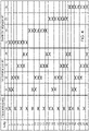
- the 4 shows the switching matrix for forward operation of the agricultural machine 1 with a transmission according to FIG 2 .
- the switching matrix shows that only one transmission unit 41, 42, 43, 44 is alternately switched in the first switching group 40 and in a subsequent gear two transmission units 41, 42, 43, 44, with the two transmission units 41, 42, 43, 44 are assigned to different output outer shaft sections 45, 46 and thus to two different power paths. A total of seven gears are thus possible with four transmission units 41, 42, 43, 44.
- the circuit of the second switching group 50 is arranged after the first switching group 40 .
- the synchronization unit 58 can connect either the transmission unit 53 or the transmission unit 57 .
- the synchronization unit 59 shifts either the transmission unit 57 or, in a direct gear, the auxiliary shaft 51b or the output shaft 30.
Landscapes
- Engineering & Computer Science (AREA)
- General Engineering & Computer Science (AREA)
- Mechanical Engineering (AREA)
- Structure Of Transmissions (AREA)
Claims (14)
- Transmission (5) comportant au moins un premier et un deuxième arbre (10, 30), au moins un premier et un deuxième groupe de commutation (40, 50) étant disposés entre le premier et le deuxième arbre (10, 30), chacun des groupes de commutation (40, 50) présentant au moins deux unités de transfert pouvant être commutées individuellement, lesquelles sont différentes les unes des autres en ce qui concerne leur rapport de démultiplication,le premier groupe de commutation (40) pouvant être amené en liaison fonctionnelle avec le premier arbre (10) par le biais d'un étage planétaire (60), qui est réalisé de telle sorte qu'une puissance mécanique introduite par le biais du premier arbre (10) peut être transférée au deuxième arbre (30) par le biais d'un premier et/ou par le biais d'un deuxième trajet de puissance pouvant être accouplé ou désaccouplé,au moins une unité de transfert du premier groupe de commutation (40) étant associée à chaque trajet de puissance et, dans au moins un état de commutation du premier groupe de commutation (40), le flux de puissance s'étendant sur au moins respectivement une unité de transfert du premier et du deuxième trajet de puissance, caractérisée en ce que le premier groupe de commutation (40) présente au moins deux parties d'arbre extérieur (45, 46) qui entourent coaxialement le premier arbre (10),au moins l'une des unités de transfert étant associée respectivement à l'une des parties d'arbre extérieur (45, 46), etune première partie d'arbre extérieur (45) étant associée au premier trajet de puissance et une deuxième partie d'arbre extérieur (46) étant associée au deuxième trajet de puissance.
- Transmission selon la revendication 1,l'étage planétaire présentant une entrée de puissance et au moins deux sorties de puissance qui sont respectivement en liaison avec l'un des trajets de puissance,un embrayage planétaire (62) étant disposé entre les deux sorties de puissance de l'étage planétaire (60), lequel embrayage relie directement l'une à l'autre les deux sorties de puissance dans un état accouplé.
- Transmission selon la revendication 2,
la première sortie de puissance étant reliée à la première partie d'arbre extérieur (45) et la deuxième sortie de puissance étant reliée à la deuxième partie d'arbre extérieur (46). - Transmission selon la revendication 2 ou 3, l'embrayage planétaire (62) étant un embrayage à disques doté d'un porte-disques intérieur et d'un porte-disques extérieur,
les porte-disques étant en liaison respectivement avec l'une des sorties de puissance de l'étage planétaire (62) et l'un des trajets de puissance, en particulier avec l'une des parties d'arbre extérieur (45, 46). - Transmission selon l'une des revendications 1 à 4,
les unités de transfert étant réalisées au moins partiellement sous forme de paires de roue dentées et/ou sous forme d'embrayage direct. - Transmission selon l'une des revendications 1 à 5, une unité d'inversion (70) pouvant être accouplée étant disposée entre le premier arbre (10) et l'étage planétaire (60), laquelle provoque une inversion du sens de rotation de l'étage planétaire (60) dans l'état accouplé.
- Transmission selon l'une des revendications 1 à 6, un troisième arbre (20) étant disposé entre le premier (10) et le deuxième arbre (30), le deuxième groupe de commutation (50) étant disposé entre le deuxième et le troisième arbre (20, 30).
- Transmission selon l'une des revendications 1 à 7, un embrayage, en particulier un embrayage à disques, étant associée au moins à chaque unité de transfert du premier groupe de commutation (40), embrayage par le biais duquel l'unité de transfert peut être accouplée ou désaccouplée.
- Transmission selon l'une des revendications 1 à 8, les unités de transfert du deuxième groupe de commutation (50) pouvant être accouplées ou désaccouplées au moins partiellement par le biais d'une unité de synchronisation (59, 58).
- Transmission selon l'une des revendications 1 à 9, le premier et/ou le deuxième groupe de commutation (40, 50) présentant au moins trois, de préférence au moins quatre unités de transfert.
- Utilisation d'une transmission (5) selon l'une des revendications 1 à 10 dans une machine agricole (1), en particulier un tracteur.
- Procédé de fonctionnement d'une transmission (5) selon l'une des revendications 1 à 10,
selon lequel on passe par les états de commutation du premier groupe de commutation (40) de telle sorte qu'en alternance soit seulement une unité de transfert du premier trajet de puissance soit respectivement une unité de transfert est raccordée à la fois dans le premier et également au moins dans le deuxième trajet de puissance. - Procédé selon la revendication 12, selon lequel l'embrayage planétaire (62) entre les sorties de puissance de l'étage planétaire n'est pas accouplé en cas de commutation commune du premier et du deuxième trajet de puissance.
- Procédé selon la revendication 12 ou 13, selon lequel on passe tour à tour tout seulement par les états de commutation du premier groupe de commutation (40) et ensuite seulement par les états de commutation du deuxième groupe de commutation (50),selon lequel lors d'un passage de vitesse supérieure de la transmission, on passe tout d'abord seulement par tous les états de commutation du premier groupe de commutation, ensuite seulement le deuxième groupe de commutation est amené à un nouvel état de commutation et on passe encore une fois par les états de commutation individuels du premier groupe de commutation, etselon lequel cette séquence est maintenue jusqu'à ce que le dernier état de commutation dans le deuxième groupe de commutation soit également atteint.
Applications Claiming Priority (1)
| Application Number | Priority Date | Filing Date | Title |
|---|---|---|---|
| DE102019216300.9A DE102019216300A1 (de) | 2019-10-23 | 2019-10-23 | Getriebe, Verwendung eines Getriebes und Verfahren für ein Getriebe |
Publications (2)
| Publication Number | Publication Date |
|---|---|
| EP3812621A1 EP3812621A1 (fr) | 2021-04-28 |
| EP3812621B1 true EP3812621B1 (fr) | 2022-09-28 |
Family
ID=72658966
Family Applications (1)
| Application Number | Title | Priority Date | Filing Date |
|---|---|---|---|
| EP20198068.7A Active EP3812621B1 (fr) | 2019-10-23 | 2020-09-24 | Engrenage, utilisation d'un engrenage et procédé pour un engrenage |
Country Status (3)
| Country | Link |
|---|---|
| US (1) | US11187310B2 (fr) |
| EP (1) | EP3812621B1 (fr) |
| DE (1) | DE102019216300A1 (fr) |
Families Citing this family (3)
| Publication number | Priority date | Publication date | Assignee | Title |
|---|---|---|---|---|
| DE102019216303A1 (de) * | 2019-10-23 | 2021-04-29 | Deere & Company | Getriebe |
| DE102019216299A1 (de) | 2019-10-23 | 2021-04-29 | Deere & Company | Schaltgruppe für Lastschaltgetriebe |
| DE102021207657B4 (de) | 2021-07-19 | 2023-03-16 | Zf Friedrichshafen Ag | Getriebeanordnung und Hybridgetriebeanordnung für ein Kraftfahrzeug |
Family Cites Families (12)
| Publication number | Priority date | Publication date | Assignee | Title |
|---|---|---|---|---|
| JP4968494B2 (ja) | 2001-03-05 | 2012-07-04 | アイシン・エィ・ダブリュ株式会社 | 車両用変速機 |
| DE10260179A1 (de) | 2002-12-20 | 2004-07-01 | Zf Friedrichshafen Ag | Mehrganggetriebe in Vorgelenebauweise mit Leistungsverzweigung |
| US8596157B2 (en) | 2010-08-25 | 2013-12-03 | Deere & Company | Powershift transmission with twenty-four forward modes |
| DE102011084037A1 (de) * | 2011-09-02 | 2013-03-07 | Schaeffler Technologies AG & Co. KG | Kraftfahrzeuggetriebe |
| DE102012021599B4 (de) * | 2012-10-30 | 2018-10-04 | Audi Ag | Schaltvorrichtung für ein Doppelkupplungsgetriebe |
| DE102012220829A1 (de) * | 2012-11-15 | 2014-05-15 | Zf Friedrichshafen Ag | Verfahren zum Betreiben einer Antriebseinheit für ein Hybridfahrzeug |
| US9879761B2 (en) | 2014-10-30 | 2018-01-30 | Deere & Company | Powershift transmission with twenty-seven forward modes |
| DE102014226469B4 (de) * | 2014-12-18 | 2023-06-07 | Airbus Helicopters Technik Gmbh | Umlaufrädergetriebe mit mehreren Lastpfaden und mechanisch begrenztem Verdrehwinkel der Pfade |
| DE102015208166A1 (de) | 2015-05-04 | 2016-11-10 | Deere & Company | Getriebeanordnung |
| DE102015208164A1 (de) | 2015-05-04 | 2016-11-10 | Deere & Company | Getriebeanordnung |
| DE102015211809A1 (de) | 2015-06-25 | 2016-12-29 | Deere & Company | Getriebeanordnung |
| US10086686B2 (en) | 2016-01-14 | 2018-10-02 | Deere & Company | Transmission with a mode selection apparatus |
-
2019
- 2019-10-23 DE DE102019216300.9A patent/DE102019216300A1/de active Pending
-
2020
- 2020-09-24 EP EP20198068.7A patent/EP3812621B1/fr active Active
- 2020-10-12 US US17/068,178 patent/US11187310B2/en active Active
Also Published As
| Publication number | Publication date |
|---|---|
| US20210123511A1 (en) | 2021-04-29 |
| US11187310B2 (en) | 2021-11-30 |
| EP3812621A1 (fr) | 2021-04-28 |
| DE102019216300A1 (de) | 2021-05-12 |
Similar Documents
| Publication | Publication Date | Title |
|---|---|---|
| DE102006058831B4 (de) | Mehrganggetriebe mit Differentialzahnradsatz und Vorgelegewellen-Zahnradanordnung | |
| EP3812621B1 (fr) | Engrenage, utilisation d'un engrenage et procédé pour un engrenage | |
| EP2742258B1 (fr) | Transmission de véhicule automobile | |
| EP2914874B1 (fr) | Transmission à double embrayage | |
| EP3532325A1 (fr) | Groupe motopropulseur hybride d'un véhicule automobile à propulsion hybride | |
| WO2016131597A1 (fr) | Boîte de vitesses à double embrayage pour véhicule à moteur | |
| DE102014004691B4 (de) | Geschwindigkeits-Wechselgetriebe für ein Kraftfahrzeug | |
| EP3812622B1 (fr) | Boîte de vitesses | |
| DE102016111282B4 (de) | Doppelkupplungsgetriebe mit Brückenkupplung | |
| DE102020202008B4 (de) | Leistungsverzweigtes stufenloses Getriebe | |
| EP3770465A1 (fr) | Boîte de vitesses | |
| EP3472490B1 (fr) | Transmission à embrayage double à embrayage de pontage | |
| DE102021211734B3 (de) | Drei- oder Vierganggetriebe für einen elektrischen Antrieb | |
| DE102020203795A1 (de) | Doppelkupplungsgetriebe und Hybrid-Antriebsstrang | |
| DE102019207925A1 (de) | Nebenabtriebsgetriebe und landwirtschaftliche Arbeitsmaschine | |
| DE102015204600B4 (de) | Getriebe für ein Kraftfahrzeug und Verfahren zum Betreiben eines solchen | |
| AT525268B1 (de) | Getriebeanordnung mit 5 losrädern im power-shift-getriebe | |
| AT525267B1 (de) | Getriebeanordnung mit 6 losrädern im power-shift-getriebe | |
| EP2864661B1 (fr) | Unité comprenant une boîte de vitesses et des embrayages et procédé de contrôle pour un agencement de transmission la comprenant | |
| DE102020201775B3 (de) | Leistungsverzweigtes stufenloses Getriebe | |
| WO2016128156A1 (fr) | Boîte de vitesses à double embrayage et procédé permettant de faire fonctionner une boîte de vitesses à double embrayage | |
| DE10238419A1 (de) | Antriebssystem | |
| DE102020203791A1 (de) | Doppelkupplungsgetriebe und Hybrid-Antriebsstrang | |
| DE102021205932A1 (de) | Getriebe und Antriebsstrang für ein Kraftfahrzeug | |
| DE102020203793A1 (de) | Doppelkupplungsgetriebe |
Legal Events
| Date | Code | Title | Description |
|---|---|---|---|
| PUAI | Public reference made under article 153(3) epc to a published international application that has entered the european phase |
Free format text: ORIGINAL CODE: 0009012 |
|
| STAA | Information on the status of an ep patent application or granted ep patent |
Free format text: STATUS: THE APPLICATION HAS BEEN PUBLISHED |
|
| AK | Designated contracting states |
Kind code of ref document: A1 Designated state(s): AL AT BE BG CH CY CZ DE DK EE ES FI FR GB GR HR HU IE IS IT LI LT LU LV MC MK MT NL NO PL PT RO RS SE SI SK SM TR |
|
| AX | Request for extension of the european patent |
Extension state: BA ME |
|
| STAA | Information on the status of an ep patent application or granted ep patent |
Free format text: STATUS: REQUEST FOR EXAMINATION WAS MADE |
|
| 17P | Request for examination filed |
Effective date: 20211028 |
|
| RBV | Designated contracting states (corrected) |
Designated state(s): AL AT BE BG CH CY CZ DE DK EE ES FI FR GB GR HR HU IE IS IT LI LT LU LV MC MK MT NL NO PL PT RO RS SE SI SK SM TR |
|
| RIC1 | Information provided on ipc code assigned before grant |
Ipc: F16H 37/08 20060101ALI20220328BHEP Ipc: F16H 37/04 20060101AFI20220328BHEP |
|
| GRAP | Despatch of communication of intention to grant a patent |
Free format text: ORIGINAL CODE: EPIDOSNIGR1 |
|
| STAA | Information on the status of an ep patent application or granted ep patent |
Free format text: STATUS: GRANT OF PATENT IS INTENDED |
|
| INTG | Intention to grant announced |
Effective date: 20220510 |
|
| GRAS | Grant fee paid |
Free format text: ORIGINAL CODE: EPIDOSNIGR3 |
|
| GRAA | (expected) grant |
Free format text: ORIGINAL CODE: 0009210 |
|
| STAA | Information on the status of an ep patent application or granted ep patent |
Free format text: STATUS: THE PATENT HAS BEEN GRANTED |
|
| AK | Designated contracting states |
Kind code of ref document: B1 Designated state(s): AL AT BE BG CH CY CZ DE DK EE ES FI FR GB GR HR HU IE IS IT LI LT LU LV MC MK MT NL NO PL PT RO RS SE SI SK SM TR |
|
| REG | Reference to a national code |
Ref country code: GB Ref legal event code: FG4D Free format text: NOT ENGLISH |
|
| REG | Reference to a national code |
Ref country code: CH Ref legal event code: EP |
|
| REG | Reference to a national code |
Ref country code: AT Ref legal event code: REF Ref document number: 1521418 Country of ref document: AT Kind code of ref document: T Effective date: 20221015 |
|
| REG | Reference to a national code |
Ref country code: DE Ref legal event code: R096 Ref document number: 502020001770 Country of ref document: DE |
|
| REG | Reference to a national code |
Ref country code: IE Ref legal event code: FG4D Free format text: LANGUAGE OF EP DOCUMENT: GERMAN |
|
| REG | Reference to a national code |
Ref country code: LT Ref legal event code: MG9D |
|
| PG25 | Lapsed in a contracting state [announced via postgrant information from national office to epo] |
Ref country code: SE Free format text: LAPSE BECAUSE OF FAILURE TO SUBMIT A TRANSLATION OF THE DESCRIPTION OR TO PAY THE FEE WITHIN THE PRESCRIBED TIME-LIMIT Effective date: 20220928 Ref country code: RS Free format text: LAPSE BECAUSE OF FAILURE TO SUBMIT A TRANSLATION OF THE DESCRIPTION OR TO PAY THE FEE WITHIN THE PRESCRIBED TIME-LIMIT Effective date: 20220928 Ref country code: NO Free format text: LAPSE BECAUSE OF FAILURE TO SUBMIT A TRANSLATION OF THE DESCRIPTION OR TO PAY THE FEE WITHIN THE PRESCRIBED TIME-LIMIT Effective date: 20221228 Ref country code: LV Free format text: LAPSE BECAUSE OF FAILURE TO SUBMIT A TRANSLATION OF THE DESCRIPTION OR TO PAY THE FEE WITHIN THE PRESCRIBED TIME-LIMIT Effective date: 20220928 Ref country code: LT Free format text: LAPSE BECAUSE OF FAILURE TO SUBMIT A TRANSLATION OF THE DESCRIPTION OR TO PAY THE FEE WITHIN THE PRESCRIBED TIME-LIMIT Effective date: 20220928 Ref country code: FI Free format text: LAPSE BECAUSE OF FAILURE TO SUBMIT A TRANSLATION OF THE DESCRIPTION OR TO PAY THE FEE WITHIN THE PRESCRIBED TIME-LIMIT Effective date: 20220928 |
|
| REG | Reference to a national code |
Ref country code: NL Ref legal event code: MP Effective date: 20220928 |
|
| PG25 | Lapsed in a contracting state [announced via postgrant information from national office to epo] |
Ref country code: HR Free format text: LAPSE BECAUSE OF FAILURE TO SUBMIT A TRANSLATION OF THE DESCRIPTION OR TO PAY THE FEE WITHIN THE PRESCRIBED TIME-LIMIT Effective date: 20220928 Ref country code: GR Free format text: LAPSE BECAUSE OF FAILURE TO SUBMIT A TRANSLATION OF THE DESCRIPTION OR TO PAY THE FEE WITHIN THE PRESCRIBED TIME-LIMIT Effective date: 20221229 |
|
| PG25 | Lapsed in a contracting state [announced via postgrant information from national office to epo] |
Ref country code: SM Free format text: LAPSE BECAUSE OF FAILURE TO SUBMIT A TRANSLATION OF THE DESCRIPTION OR TO PAY THE FEE WITHIN THE PRESCRIBED TIME-LIMIT Effective date: 20220928 Ref country code: RO Free format text: LAPSE BECAUSE OF FAILURE TO SUBMIT A TRANSLATION OF THE DESCRIPTION OR TO PAY THE FEE WITHIN THE PRESCRIBED TIME-LIMIT Effective date: 20220928 Ref country code: PT Free format text: LAPSE BECAUSE OF FAILURE TO SUBMIT A TRANSLATION OF THE DESCRIPTION OR TO PAY THE FEE WITHIN THE PRESCRIBED TIME-LIMIT Effective date: 20230130 Ref country code: ES Free format text: LAPSE BECAUSE OF FAILURE TO SUBMIT A TRANSLATION OF THE DESCRIPTION OR TO PAY THE FEE WITHIN THE PRESCRIBED TIME-LIMIT Effective date: 20220928 Ref country code: CZ Free format text: LAPSE BECAUSE OF FAILURE TO SUBMIT A TRANSLATION OF THE DESCRIPTION OR TO PAY THE FEE WITHIN THE PRESCRIBED TIME-LIMIT Effective date: 20220928 |
|
| PG25 | Lapsed in a contracting state [announced via postgrant information from national office to epo] |
Ref country code: SK Free format text: LAPSE BECAUSE OF FAILURE TO SUBMIT A TRANSLATION OF THE DESCRIPTION OR TO PAY THE FEE WITHIN THE PRESCRIBED TIME-LIMIT Effective date: 20220928 Ref country code: PL Free format text: LAPSE BECAUSE OF FAILURE TO SUBMIT A TRANSLATION OF THE DESCRIPTION OR TO PAY THE FEE WITHIN THE PRESCRIBED TIME-LIMIT Effective date: 20220928 Ref country code: IS Free format text: LAPSE BECAUSE OF FAILURE TO SUBMIT A TRANSLATION OF THE DESCRIPTION OR TO PAY THE FEE WITHIN THE PRESCRIBED TIME-LIMIT Effective date: 20230128 Ref country code: EE Free format text: LAPSE BECAUSE OF FAILURE TO SUBMIT A TRANSLATION OF THE DESCRIPTION OR TO PAY THE FEE WITHIN THE PRESCRIBED TIME-LIMIT Effective date: 20220928 |
|
| REG | Reference to a national code |
Ref country code: DE Ref legal event code: R097 Ref document number: 502020001770 Country of ref document: DE |
|
| PG25 | Lapsed in a contracting state [announced via postgrant information from national office to epo] |
Ref country code: NL Free format text: LAPSE BECAUSE OF FAILURE TO SUBMIT A TRANSLATION OF THE DESCRIPTION OR TO PAY THE FEE WITHIN THE PRESCRIBED TIME-LIMIT Effective date: 20220928 Ref country code: AL Free format text: LAPSE BECAUSE OF FAILURE TO SUBMIT A TRANSLATION OF THE DESCRIPTION OR TO PAY THE FEE WITHIN THE PRESCRIBED TIME-LIMIT Effective date: 20220928 |
|
| PG25 | Lapsed in a contracting state [announced via postgrant information from national office to epo] |
Ref country code: DK Free format text: LAPSE BECAUSE OF FAILURE TO SUBMIT A TRANSLATION OF THE DESCRIPTION OR TO PAY THE FEE WITHIN THE PRESCRIBED TIME-LIMIT Effective date: 20220928 |
|
| PLBE | No opposition filed within time limit |
Free format text: ORIGINAL CODE: 0009261 |
|
| STAA | Information on the status of an ep patent application or granted ep patent |
Free format text: STATUS: NO OPPOSITION FILED WITHIN TIME LIMIT |
|
| 26N | No opposition filed |
Effective date: 20230629 |
|
| PG25 | Lapsed in a contracting state [announced via postgrant information from national office to epo] |
Ref country code: SI Free format text: LAPSE BECAUSE OF FAILURE TO SUBMIT A TRANSLATION OF THE DESCRIPTION OR TO PAY THE FEE WITHIN THE PRESCRIBED TIME-LIMIT Effective date: 20220928 |
|
| PGFP | Annual fee paid to national office [announced via postgrant information from national office to epo] |
Ref country code: DE Payment date: 20230821 Year of fee payment: 4 Ref country code: FR Payment date: 20230925 Year of fee payment: 4 |
|
| REG | Reference to a national code |
Ref country code: CH Ref legal event code: PL |
|
| PG25 | Lapsed in a contracting state [announced via postgrant information from national office to epo] |
Ref country code: LU Free format text: LAPSE BECAUSE OF NON-PAYMENT OF DUE FEES Effective date: 20230924 |