EP3812570B1 - Gas turbine engine with low fan pressure ratio - Google Patents
Gas turbine engine with low fan pressure ratio Download PDFInfo
- Publication number
- EP3812570B1 EP3812570B1 EP20210919.5A EP20210919A EP3812570B1 EP 3812570 B1 EP3812570 B1 EP 3812570B1 EP 20210919 A EP20210919 A EP 20210919A EP 3812570 B1 EP3812570 B1 EP 3812570B1
- Authority
- EP
- European Patent Office
- Prior art keywords
- fan
- engine
- nacelle
- core
- recited
- Prior art date
- Legal status (The legal status is an assumption and is not a legal conclusion. Google has not performed a legal analysis and makes no representation as to the accuracy of the status listed.)
- Active
Links
Images


Classifications
-
- F—MECHANICAL ENGINEERING; LIGHTING; HEATING; WEAPONS; BLASTING
- F04—POSITIVE - DISPLACEMENT MACHINES FOR LIQUIDS; PUMPS FOR LIQUIDS OR ELASTIC FLUIDS
- F04D—NON-POSITIVE-DISPLACEMENT PUMPS
- F04D29/00—Details, component parts, or accessories
- F04D29/40—Casings; Connections of working fluid
- F04D29/52—Casings; Connections of working fluid for axial pumps
- F04D29/54—Fluid-guiding means, e.g. diffusers
- F04D29/56—Fluid-guiding means, e.g. diffusers adjustable
- F04D29/563—Fluid-guiding means, e.g. diffusers adjustable specially adapted for elastic fluid pumps
-
- F—MECHANICAL ENGINEERING; LIGHTING; HEATING; WEAPONS; BLASTING
- F01—MACHINES OR ENGINES IN GENERAL; ENGINE PLANTS IN GENERAL; STEAM ENGINES
- F01D—NON-POSITIVE DISPLACEMENT MACHINES OR ENGINES, e.g. STEAM TURBINES
- F01D17/00—Regulating or controlling by varying flow
- F01D17/10—Final actuators
- F01D17/12—Final actuators arranged in stator parts
- F01D17/14—Final actuators arranged in stator parts varying effective cross-sectional area of nozzles or guide conduits
- F01D17/16—Final actuators arranged in stator parts varying effective cross-sectional area of nozzles or guide conduits by means of nozzle vanes
- F01D17/162—Final actuators arranged in stator parts varying effective cross-sectional area of nozzles or guide conduits by means of nozzle vanes for axial flow, i.e. the vanes turning around axes which are essentially perpendicular to the rotor centre line
-
- F—MECHANICAL ENGINEERING; LIGHTING; HEATING; WEAPONS; BLASTING
- F02—COMBUSTION ENGINES; HOT-GAS OR COMBUSTION-PRODUCT ENGINE PLANTS
- F02K—JET-PROPULSION PLANTS
- F02K1/00—Plants characterised by the form or arrangement of the jet pipe or nozzle; Jet pipes or nozzles peculiar thereto
- F02K1/06—Varying effective area of jet pipe or nozzle
- F02K1/15—Control or regulation
- F02K1/16—Control or regulation conjointly with another control
-
- F—MECHANICAL ENGINEERING; LIGHTING; HEATING; WEAPONS; BLASTING
- F02—COMBUSTION ENGINES; HOT-GAS OR COMBUSTION-PRODUCT ENGINE PLANTS
- F02K—JET-PROPULSION PLANTS
- F02K3/00—Plants including a gas turbine driving a compressor or a ducted fan
- F02K3/02—Plants including a gas turbine driving a compressor or a ducted fan in which part of the working fluid by-passes the turbine and combustion chamber
- F02K3/04—Plants including a gas turbine driving a compressor or a ducted fan in which part of the working fluid by-passes the turbine and combustion chamber the plant including ducted fans, i.e. fans with high volume, low pressure outputs, for augmenting the jet thrust, e.g. of double-flow type
- F02K3/075—Plants including a gas turbine driving a compressor or a ducted fan in which part of the working fluid by-passes the turbine and combustion chamber the plant including ducted fans, i.e. fans with high volume, low pressure outputs, for augmenting the jet thrust, e.g. of double-flow type controlling flow ratio between flows
-
- F—MECHANICAL ENGINEERING; LIGHTING; HEATING; WEAPONS; BLASTING
- F01—MACHINES OR ENGINES IN GENERAL; ENGINE PLANTS IN GENERAL; STEAM ENGINES
- F01D—NON-POSITIVE DISPLACEMENT MACHINES OR ENGINES, e.g. STEAM TURBINES
- F01D5/00—Blades; Blade-carrying members; Heating, heat-insulating, cooling or antivibration means on the blades or the members
- F01D5/12—Blades
- F01D5/14—Form or construction
- F01D5/141—Shape, i.e. outer, aerodynamic form
- F01D5/146—Shape, i.e. outer, aerodynamic form of blades with tandem configuration, split blades or slotted blades
-
- F—MECHANICAL ENGINEERING; LIGHTING; HEATING; WEAPONS; BLASTING
- F05—INDEXING SCHEMES RELATING TO ENGINES OR PUMPS IN VARIOUS SUBCLASSES OF CLASSES F01-F04
- F05D—INDEXING SCHEME FOR ASPECTS RELATING TO NON-POSITIVE-DISPLACEMENT MACHINES OR ENGINES, GAS-TURBINES OR JET-PROPULSION PLANTS
- F05D2220/00—Application
- F05D2220/30—Application in turbines
- F05D2220/36—Application in turbines specially adapted for the fan of turbofan engines
-
- F—MECHANICAL ENGINEERING; LIGHTING; HEATING; WEAPONS; BLASTING
- F05—INDEXING SCHEMES RELATING TO ENGINES OR PUMPS IN VARIOUS SUBCLASSES OF CLASSES F01-F04
- F05D—INDEXING SCHEME FOR ASPECTS RELATING TO NON-POSITIVE-DISPLACEMENT MACHINES OR ENGINES, GAS-TURBINES OR JET-PROPULSION PLANTS
- F05D2260/00—Function
- F05D2260/40—Transmission of power
- F05D2260/403—Transmission of power through the shape of the drive components
- F05D2260/4031—Transmission of power through the shape of the drive components as in toothed gearing
- F05D2260/40311—Transmission of power through the shape of the drive components as in toothed gearing of the epicyclical, planetary or differential type
-
- F—MECHANICAL ENGINEERING; LIGHTING; HEATING; WEAPONS; BLASTING
- F05—INDEXING SCHEMES RELATING TO ENGINES OR PUMPS IN VARIOUS SUBCLASSES OF CLASSES F01-F04
- F05D—INDEXING SCHEME FOR ASPECTS RELATING TO NON-POSITIVE-DISPLACEMENT MACHINES OR ENGINES, GAS-TURBINES OR JET-PROPULSION PLANTS
- F05D2270/00—Control
- F05D2270/30—Control parameters, e.g. input parameters
- F05D2270/301—Pressure
- F05D2270/3015—Pressure differential pressure
Definitions
- the present invention relates to a gas turbine engine, and more particularly to a turbofan engine having a variable geometry fan exit guide vane (FEGV) system to change a fan bypass flow path area thereof.
- FEGV variable geometry fan exit guide vane
- Conventional gas turbine engines generally include a fan section and a core section with the fan section having a larger diameter than that of the core section.
- the fan section and the core section are disposed about a longitudinal axis and are enclosed within an engine nacelle assembly.
- Combustion gases are discharged from the core section through a core exhaust nozzle while an annular fan bypass flow, disposed radially outward of the primary core exhaust path, is discharged along a fan bypass flow path and through an annular fan exhaust nozzle.
- a majority of thrust is produced by the bypass flow while the remainder is provided from the combustion gases.
- the fan bypass flow path is a compromise suitable for take-off and landing conditions as well as for cruise conditions.
- a minimum area along the fan bypass flow path determines the maximum mass flow of air.
- insufficient flow area along the bypass flow path may result in significant flow spillage and associated drag.
- the fan nacelle diameter is typically sized to minimize drag during these engine-out conditions which results in a fan nacelle diameter that is larger than necessary at normal cruise conditions with less than optimal drag during portions of an aircraft mission.
- the multiple of fan exit guide vanes may be simultaneously rotatable. Additionally or alternatively, the multiple of fan exit guide vanes may be mounted within an intermediate engine case structure. Additionally or alternatively, each of the multiple of fan exit guide vanes may include a pivotable portion rotatable about the axis of rotation relative a fixed portion.
- the pivotable portion may include a leading edge flap.
- the controller may be operable to control the fan nozzle exit area to reduce a fan instability.
- the engine may further include a gear system driven by a core engine within the core nacelle to drive a fan within the fan nacelle, the fan defines a corrected fan tip speed less than about 1150 ft / second (350.5 m/s).
- the engine may further include a gear system driven by a core engine within the core nacelle to drive a fan within the fan nacelle, the gear system defines a gear reduction ratio of greater than or equal to about 2.3.
- the engine may further include a gear system driven by a core engine within the core nacelle to drive a fan within the fan nacelle, the gear system defines a gear reduction ratio of greater than or equal to about 2.5.
- the engine may further include a gear system driven by the core engine to drive the fan, the gear system defines a gear reduction ratio of greater than or equal to 2.5.
- the engine bypass flow may define a bypass ratio greater than about ten (10). Additionally or alternatively, the bypass flow may define a bypass ratio greater than ten (10).
- Figure 1 illustrates a general partial fragmentary schematic view of a gas turbofan engine 10 suspended from an engine pylon P within an engine nacelle assembly N as is typical of an aircraft designed for subsonic operation.
- the turbofan engine 10 includes a core section within a core nacelle 12 that houses a low spool 14 and high spool 24.
- the low spool 14 includes a low pressure compressor 16 and low pressure turbine 18.
- the low spool 14 drives a fan section 20 directly or through a gear train 22.
- the high spool 24 includes a high pressure compressor 26 and high pressure turbine 28.
- a combustor 30 is arranged between the high pressure compressor 26 and high pressure turbine 28.
- the low and high spools 14, 24 rotate about an engine axis of rotation A.
- the engine 10 is a high-bypass geared architecture aircraft engine.
- the engine 10 bypass ratio is greater than six, with an example embodiment being greater than about ten
- the gear train 22 is an epicyclic gear train such as a planetary gear system or other gear system with a gear reduction ratio of greater than about 2.3
- the low pressure turbine 18 has a pressure ratio that is greater than about five.
- the engine 10 in the disclosed embodiment is a high-bypass geared turbofan aircraft engine in which the engine 10 bypass ratio is greater than ten, the turbofan diameter is significantly larger than that of the low pressure compressor 16, and the low pressure turbine 18 has a pressure ratio greater than five.
- Low pressure turbine 18 pressure ratio is pressure measured prior to inlet of low pressure turbine 18 as related to the pressure at the outlet of the low pressure turbine 18 prior to exhaust nozzle.
- the gear train 22 may be an epicycle gear train such as a planetary gear system or other gear system with a gear reduction ratio of greater than about 2.5. It should be understood, however, that the above parameters are exemplary of only one geared turbofan engine and that the present invention is likewise applicable to other gas turbine engines including direct drive turbofans.
- the fan section 20 communicates airflow into the core nacelle 12 for compression by the low pressure compressor 16 and the high pressure compressor 26. Core airflow compressed by the low pressure compressor 16 and the high pressure compressor 26 is mixed with the fuel in the combustor 30 then expanded over the high pressure turbine 28 and low pressure turbine 18.
- the turbines 28, 18 are coupled for rotation with respective spools 24, 14 to rotationally drive the compressors 26, 16 and, through the gear train 22, the fan section 20 in response to the expansion.
- a core engine exhaust E exits the core nacelle 12 through a core nozzle 43 defined between the core nacelle 12 and a tail cone 32.
- a bypass flow path 40 is defined between the core nacelle 12 and the fan nacelle 34.
- the engine 10 generates a high bypass flow arrangement with a bypass ratio in which approximately 80 percent of the airflow entering the fan nacelle 34 becomes bypass flow B.
- the bypass flow B communicates through the generally annular bypass flow path 40 and may be discharged from the engine 10 through a fan variable area nozzle (FVAN) 42 which defines a variable fan nozzle exit area 44 between the fan nacelle 34 and the core nacelle 12 at an aft segment 34S of the fan nacelle 34 downstream of the fan section 20.
- FVAN fan variable area nozzle
- the core nacelle 12 is generally supported upon a core engine case structure 46.
- a fan case structure 48 is defined about the core engine case structure 46 to support the fan nacelle 34.
- the core engine case structure 46 is secured to the fan case 48 through a multiple of circumferentially spaced radially extending fan exit guide vanes (FEGV) 50.
- the fan case structure 48, the core engine case structure 46, and the multiple of circumferentially spaced radially extending fan exit guide vanes 50 which extend therebetween is typically a complete unit often referred to as an intermediate case. It should be understood that the fan exit guide vanes 50 may be of various forms.
- the intermediate case structure in the disclosed embodiment includes a variable geometry fan exit guide vane (FEGV) system 36.
- Thrust is a function of density, velocity, and area. One or more of these parameters can be manipulated to vary the amount and direction of thrust provided by the bypass flow B. A significant amount of thrust is provided by the bypass flow B due to the high bypass ratio.
- the fan section 20 of the engine 10 is nominally designed for a particular flight condition - - typically cruise at about 0.8 Mach and about 35,000 feet (10,668 m).
- the flight condition of 0.8 Mach and 35,000 ft (10,668 m) with the engine at its best fuel consumption - also known as "bucket cruise Thrust Specific Fuel Consumption ('TSFC')" - is the industry standard parameter of lbm of fuel being burned divided by lbf of thrust the engine produces at that minimum point.
- Low fan pressure ratio is the pressure ratio across the fan blade alone, without the fan exit guide vane (FEGV) system 36.
- the low fan pressure ratio is less than 1.45.
- the "Low corrected fan tip speed” as disclosed herein according to one non-limiting embodiment is less than about 1150 ft / second (350.5 m/s).
- the FEGV system 36 and/or the FVAN 42 is operated to adjust fan bypass air flow such that the angle of attack or incidence of the fan blades is maintained close to the design incidence for efficient engine operation at other flight conditions, such as landing and takeoff.
- the FEGV system 36 and/or the FVAN 42 may be adjusted to selectively adjust the pressure ratio of the bypass flow B in response to a controller C. For example, increased mass flow during windmill or engine-out, and spoiling thrust at landing.
- the FEGV system 36 will facilitate and in some instances replace the FVAN 42, such as, for example, variable flow area is utilized to manage and optimize the fan operating lines which provides operability margin and allows the fan to be operated near peak efficiency which enables a low fan pressure-ratio and low fan tip speed design; and the variable area reduces noise by improving fan blade aerodynamics by varying blade incidence.
- the FEGV system 36 thereby provides optimized engine operation over a range of flight conditions with respect to performance and other operational parameters such as noise levels.
- each fan exit guide vane 50 includes a respective airfoil portion 52 defined by an outer airfoil wall surface 54 between the leading edge 56 and a trailing edge 58.
- the outer airfoil wall 54 typically has a generally concave shaped portion forming a pressure side and a generally convex shaped portion forming a suction side.
- respective airfoil portion 52 defined by the outer airfoil wall surface 54 may be generally equivalent or separately tailored to optimize flow characteristics.
- Each fan exit guide vane 50 is mounted about a vane longitudinal axis of rotation 60.
- the vane axis of rotation 60 is typically transverse to the engine axis A, or at an angle to engine axis A.
- various support struts 61 or other such members may be located through the airfoil portion 52 to provide fixed support structure between the core engine case structure 46 and the fan case structure 48.
- the axis of rotation 60 may be located about the geometric center of gravity (CG) of the airfoil cross section.
- An actuator system 62 illustrated schematically; Figure 1A ), for example only, a unison ring operates to rotate each fan exit guide vane 50 to selectively vary the fan nozzle throat area ( Figure 2B ).
- the unison ring may be located, for example, in the intermediate case structure such as within either or both of the core engine case structure 46 or the fan case 48 ( Figure 1A ).
- the FEGV system 36 communicates with the controller C to rotate the fan exit guide vanes 50 and effectively vary the fan nozzle exit area 44.
- Other control systems including an engine controller or an aircraft flight control system may also be usable with the present invention.
- Rotation of the fan exit guide vanes 50 between a nominal position and a rotated position selectively changes the fan bypass flow path 40. That is, both the throat area ( Figure 2B ) and the projected area ( Figure 2C ) are varied through adjustment of the fan exit guide vanes 50.
- bypass flow B is increased for particular flight conditions such as during an engine-out condition.
- engine bypass flow may be selectively vectored to provide, for example only, trim balance, thrust controlled maneuvering, enhanced ground operations and short field performance.
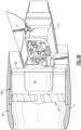
- FIG. 3A another embodiment of the FEGV system 36' includes a multiple of fan exit guide vane 50' which each includes a fixed airfoil portion 66F and pivoting airfoil portion 66P which pivots relative to the fixed airfoil portion 66F.
- the pivoting airfoil portion 66P may include a leading edge flap which is actuatable by an actuator system 62' as described above to vary both the throat area ( Figure 3B ) and the projected area ( Figure 3C ).
- FIG. 4A another embodiment of the FEGV system 36" includes a multiple of slotted fan exit guide vane 50" which each includes a fixed airfoil portion 68F and pivoting and sliding airfoil portion 68P which pivots and slides relative to the fixed airfoil portion 68F to create a slot 70 vary both the throat area ( Figure 4B ) and the projected area ( Figure 4C ) as generally described above.
- This slatted vane method not only increases the flow area but also provides the additional benefit that when there is a negative incidence on the fan exit guide vane 50" allows air flow from the high-pressure, convex side of the fan exit guide vane 50" to the lowerpressure, concave side of the fan exit guide vane 50" which delays flow separation.
Landscapes
- Engineering & Computer Science (AREA)
- Mechanical Engineering (AREA)
- General Engineering & Computer Science (AREA)
- Chemical & Material Sciences (AREA)
- Combustion & Propulsion (AREA)
- Structures Of Non-Positive Displacement Pumps (AREA)
Description
- The present invention relates to a gas turbine engine, and more particularly to a turbofan engine having a variable geometry fan exit guide vane (FEGV) system to change a fan bypass flow path area thereof.
- Conventional gas turbine engines generally include a fan section and a core section with the fan section having a larger diameter than that of the core section. The fan section and the core section are disposed about a longitudinal axis and are enclosed within an engine nacelle assembly. Combustion gases are discharged from the core section through a core exhaust nozzle while an annular fan bypass flow, disposed radially outward of the primary core exhaust path, is discharged along a fan bypass flow path and through an annular fan exhaust nozzle. A majority of thrust is produced by the bypass flow while the remainder is provided from the combustion gases.
- The fan bypass flow path is a compromise suitable for take-off and landing conditions as well as for cruise conditions. A minimum area along the fan bypass flow path determines the maximum mass flow of air. During engine-out conditions, insufficient flow area along the bypass flow path may result in significant flow spillage and associated drag. The fan nacelle diameter is typically sized to minimize drag during these engine-out conditions which results in a fan nacelle diameter that is larger than necessary at normal cruise conditions with less than optimal drag during portions of an aircraft mission.
- A prior art gas turbine engine having the features of the preamble of
claim 1 is disclosed inUS 2009/277155 A1 .EP 2 022 949 A2 discloses another prior art gas turbine engine. - According to the present invention, there is provided a gas turbine engine as claimed in
claim 1. - In a non-limiting embodiment, the multiple of fan exit guide vanes may be simultaneously rotatable. Additionally or alternatively, the multiple of fan exit guide vanes may be mounted within an intermediate engine case structure. Additionally or alternatively, each of the multiple of fan exit guide vanes may include a pivotable portion rotatable about the axis of rotation relative a fixed portion.
- In a further non-limiting embodiment of any of the foregoing gas turbine engine embodiments, the pivotable portion may include a leading edge flap.
- In a further non-limiting embodiment, the controller may be operable to control the fan nozzle exit area to reduce a fan instability.
- In a further non-limiting embodiment of any of the foregoing gas turbine engine embodiments, the engine may further include a gear system driven by a core engine within the core nacelle to drive a fan within the fan nacelle, the fan defines a corrected fan tip speed less than about 1150 ft / second (350.5 m/s).
- In a further non-limiting embodiment of any of the foregoing gas turbine engine embodiments, the engine may further include a gear system driven by a core engine within the core nacelle to drive a fan within the fan nacelle, the gear system defines a gear reduction ratio of greater than or equal to about 2.3.
- In a further non-limiting embodiment of any of the foregoing gas turbine engine embodiments, the engine may further include a gear system driven by a core engine within the core nacelle to drive a fan within the fan nacelle, the gear system defines a gear reduction ratio of greater than or equal to about 2.5.
- In a further non-limiting embodiment of any of the foregoing gas turbine engine embodiments, the engine may further include a gear system driven by the core engine to drive the fan, the gear system defines a gear reduction ratio of greater than or equal to 2.5.
- In a further non-limiting embodiment of any of the foregoing gas turbine engine embodiments, the engine bypass flow may define a bypass ratio greater than about ten (10). Additionally or alternatively, the bypass flow may define a bypass ratio greater than ten (10).
- The various features and advantages of this invention will become apparent to those skilled in the art from the following detailed description of the currently preferred embodiment. The drawings that accompany the detailed description can be briefly described as follows:
-
Figure 1A is a general schematic partial fragmentary view of an exemplary gas turbine engine embodiment for use with the present invention; -
Figure 1B is a perspective side partial fragmentary view of a FEGV system which provides a fan variable area nozzle; -
Figure 2A is a sectional view of a single FEGV airfoil; -
Figure 2B is a sectional view of the FEGV illustrated inFigure 2A shown in a first position; -
Figure 2C is a sectional view of the FEGV illustrated inFigure 2A shown in a rotated position; -
Figure 3A is a sectional view of another embodiment of a single FEGV airfoil; -
Figures 3B is a sectional view of the FEGV illustrated inFigure 3A shown in a first position; -
Figure 3C is a sectional view of the FEGV illustrated inFigure 3A shown in a rotated position; -
Figure 4A is a sectional view of another embodiment of a single FEGV slatted airfoil with a ; -
Figures 4B is a sectional view of the FEGV illustrated inFigure 4A shown in a first position; and -
Figure 4C is a sectional view of the FEGV illustrated inFigure 4A shown in a rotated position. -
Figure 1 illustrates a general partial fragmentary schematic view of agas turbofan engine 10 suspended from an engine pylon P within an engine nacelle assembly N as is typical of an aircraft designed for subsonic operation. - The
turbofan engine 10 includes a core section within acore nacelle 12 that houses a low spool 14 andhigh spool 24. The low spool 14 includes alow pressure compressor 16 andlow pressure turbine 18. The low spool 14 drives afan section 20 directly or through agear train 22. Thehigh spool 24 includes ahigh pressure compressor 26 andhigh pressure turbine 28. Acombustor 30 is arranged between thehigh pressure compressor 26 andhigh pressure turbine 28. The low andhigh spools 14, 24 rotate about an engine axis of rotation A. - The
engine 10 is a high-bypass geared architecture aircraft engine. Theengine 10 bypass ratio is greater than six, with an example embodiment being greater than about ten, thegear train 22 is an epicyclic gear train such as a planetary gear system or other gear system with a gear reduction ratio of greater than about 2.3 and thelow pressure turbine 18 has a pressure ratio that is greater than about five. Theengine 10 in the disclosed embodiment is a high-bypass geared turbofan aircraft engine in which theengine 10 bypass ratio is greater than ten, the turbofan diameter is significantly larger than that of thelow pressure compressor 16, and thelow pressure turbine 18 has a pressure ratio greater than five.Low pressure turbine 18 pressure ratio is pressure measured prior to inlet oflow pressure turbine 18 as related to the pressure at the outlet of thelow pressure turbine 18 prior to exhaust nozzle. Thegear train 22 may be an epicycle gear train such as a planetary gear system or other gear system with a gear reduction ratio of greater than about 2.5. It should be understood, however, that the above parameters are exemplary of only one geared turbofan engine and that the present invention is likewise applicable to other gas turbine engines including direct drive turbofans. - Airflow enters a
fan nacelle 34, which may at least partially surround thecore nacelle 12. Thefan section 20 communicates airflow into thecore nacelle 12 for compression by thelow pressure compressor 16 and thehigh pressure compressor 26. Core airflow compressed by thelow pressure compressor 16 and thehigh pressure compressor 26 is mixed with the fuel in thecombustor 30 then expanded over thehigh pressure turbine 28 andlow pressure turbine 18. Theturbines respective spools 24, 14 to rotationally drive thecompressors gear train 22, thefan section 20 in response to the expansion. A core engine exhaust E exits thecore nacelle 12 through acore nozzle 43 defined between thecore nacelle 12 and atail cone 32. - A
bypass flow path 40 is defined between thecore nacelle 12 and thefan nacelle 34. Theengine 10 generates a high bypass flow arrangement with a bypass ratio in which approximately 80 percent of the airflow entering thefan nacelle 34 becomes bypass flow B. The bypass flow B communicates through the generally annularbypass flow path 40 and may be discharged from theengine 10 through a fan variable area nozzle (FVAN) 42 which defines a variable fannozzle exit area 44 between thefan nacelle 34 and thecore nacelle 12 at anaft segment 34S of thefan nacelle 34 downstream of thefan section 20. - Referring to
Figure 1B , thecore nacelle 12 is generally supported upon a coreengine case structure 46. Afan case structure 48 is defined about the coreengine case structure 46 to support thefan nacelle 34. The coreengine case structure 46 is secured to thefan case 48 through a multiple of circumferentially spaced radially extending fan exit guide vanes (FEGV) 50. Thefan case structure 48, the coreengine case structure 46, and the multiple of circumferentially spaced radially extending fanexit guide vanes 50 which extend therebetween is typically a complete unit often referred to as an intermediate case. It should be understood that the fanexit guide vanes 50 may be of various forms. The intermediate case structure in the disclosed embodiment includes a variable geometry fan exit guide vane (FEGV)system 36. - Thrust is a function of density, velocity, and area. One or more of these parameters can be manipulated to vary the amount and direction of thrust provided by the bypass flow B. A significant amount of thrust is provided by the bypass flow B due to the high bypass ratio. The
fan section 20 of theengine 10 is nominally designed for a particular flight condition - - typically cruise at about 0.8 Mach and about 35,000 feet (10,668 m). The flight condition of 0.8 Mach and 35,000 ft (10,668 m), with the engine at its best fuel consumption - also known as "bucket cruise Thrust Specific Fuel Consumption ('TSFC')" - is the industry standard parameter of lbm of fuel being burned divided by lbf of thrust the engine produces at that minimum point. "Low fan pressure ratio" is the pressure ratio across the fan blade alone, without the fan exit guide vane (FEGV)system 36. The low fan pressure ratio is less than 1.45. "Low corrected fan tip speed" is the actual fan tip speed in ft/sec divided by an industry standard temperature correction of [(Tambient deg R) / 518.7)^0.5] (where deg R = K x 9/5). The "Low corrected fan tip speed" as disclosed herein according to one non-limiting embodiment is less than about 1150 ft / second (350.5 m/s). - As the
fan section 20 is efficiently designed at a particular fixed stagger angle for an efficient cruise condition, theFEGV system 36 and/or theFVAN 42 is operated to adjust fan bypass air flow such that the angle of attack or incidence of the fan blades is maintained close to the design incidence for efficient engine operation at other flight conditions, such as landing and takeoff. TheFEGV system 36 and/or theFVAN 42 may be adjusted to selectively adjust the pressure ratio of the bypass flow B in response to a controller C. For example, increased mass flow during windmill or engine-out, and spoiling thrust at landing. Furthermore, theFEGV system 36 will facilitate and in some instances replace theFVAN 42, such as, for example, variable flow area is utilized to manage and optimize the fan operating lines which provides operability margin and allows the fan to be operated near peak efficiency which enables a low fan pressure-ratio and low fan tip speed design; and the variable area reduces noise by improving fan blade aerodynamics by varying blade incidence. TheFEGV system 36 thereby provides optimized engine operation over a range of flight conditions with respect to performance and other operational parameters such as noise levels. - Referring to
Figure 2A , each fanexit guide vane 50 includes arespective airfoil portion 52 defined by an outerairfoil wall surface 54 between theleading edge 56 and a trailingedge 58. Theouter airfoil wall 54 typically has a generally concave shaped portion forming a pressure side and a generally convex shaped portion forming a suction side. It should be understood thatrespective airfoil portion 52 defined by the outerairfoil wall surface 54 may be generally equivalent or separately tailored to optimize flow characteristics. - Each fan
exit guide vane 50 is mounted about a vane longitudinal axis ofrotation 60. The vane axis ofrotation 60 is typically transverse to the engine axis A, or at an angle to engine axis A. It should be understood that various support struts 61 or other such members may be located through theairfoil portion 52 to provide fixed support structure between the coreengine case structure 46 and thefan case structure 48. The axis ofrotation 60 may be located about the geometric center of gravity (CG) of the airfoil cross section. An actuator system 62 (illustrated schematically;Figure 1A ), for example only, a unison ring operates to rotate each fanexit guide vane 50 to selectively vary the fan nozzle throat area (Figure 2B ). The unison ring may be located, for example, in the intermediate case structure such as within either or both of the coreengine case structure 46 or the fan case 48 (Figure 1A ). - In operation, the
FEGV system 36 communicates with the controller C to rotate the fanexit guide vanes 50 and effectively vary the fannozzle exit area 44. Other control systems including an engine controller or an aircraft flight control system may also be usable with the present invention. Rotation of the fanexit guide vanes 50 between a nominal position and a rotated position selectively changes the fanbypass flow path 40. That is, both the throat area (Figure 2B ) and the projected area (Figure 2C ) are varied through adjustment of the fan exit guide vanes 50. By adjusting the fan exit guide vanes 50 (Figure 2C ), bypass flow B is increased for particular flight conditions such as during an engine-out condition. Since less bypass flow will spill around the outside of thefan nacelle 34, the maximum diameter of the fan nacelle required to avoid flow separation may be decreased. This will thereby decrease fan nacelle drag during normal cruise conditions and reduce weight of the nacelle assembly. Conversely, by closing theFEGV system 36 to decrease flow area relative to a given bypass flow, engine thrust is significantly spoiled to thereby minimize or eliminate thrust reverser requirements and further decrease weight and packaging requirements. It should be understood that other arrangements as well as essentially infinite intermediate positions are likewise usable with the present invention. - By adjusting the
FEGV system 36 in which all the fanexit guide vanes 50 are moved simultaneously, engine thrust and fuel economy are maximized during each flight regime. By separately adjusting only particular fanexit guide vanes 50 to provide an asymmetrical fanbypass flow path 40, engine bypass flow may be selectively vectored to provide, for example only, trim balance, thrust controlled maneuvering, enhanced ground operations and short field performance. - Referring to
Figure 3A , another embodiment of the FEGV system 36' includes a multiple of fan exit guide vane 50' which each includes a fixedairfoil portion 66F and pivotingairfoil portion 66P which pivots relative to the fixedairfoil portion 66F. The pivotingairfoil portion 66P may include a leading edge flap which is actuatable by an actuator system 62' as described above to vary both the throat area (Figure 3B ) and the projected area (Figure 3C ). - Referring to
Figure 4A , another embodiment of theFEGV system 36" includes a multiple of slotted fanexit guide vane 50" which each includes a fixed airfoil portion 68F and pivoting and slidingairfoil portion 68P which pivots and slides relative to the fixed airfoil portion 68F to create aslot 70 vary both the throat area (Figure 4B ) and the projected area (Figure 4C ) as generally described above. This slatted vane method not only increases the flow area but also provides the additional benefit that when there is a negative incidence on the fanexit guide vane 50" allows air flow from the high-pressure, convex side of the fanexit guide vane 50" to the lowerpressure, concave side of the fanexit guide vane 50" which delays flow separation. - The foregoing description is exemplary rather than defined by the limitations within. Many modifications and variations of the present invention are possible in light of the above teachings. The preferred embodiments of this invention have been disclosed, however, one of ordinary skill in the art would recognize that certain modifications would come within the scope of this invention. It is, therefore, to be understood that within the scope of the appended claims, the invention may be practiced otherwise than as specifically described. For that reason the following claims should be studied to determine the true scope and content of this invention.
Claims (11)
- A gas turbine engine (10) comprising:a core nacelle (12) defined about an engine centerline axis (A);a fan nacelle (34) mounted at least partially around said core nacelle (12) to define a fan bypass airflow path (B) for a fan bypass airflow (B) having a bypass ratio greater than six;
a fan variable area nozzle (42) axially movable relative said fan nacelle (34) to vary a fan nozzle exit area (44) and adjust a pressure ratio of the fan bypass airflow (B) during engine operation; anda controller (C) operable to control said fan variable area nozzle (42) to vary said fan nozzle exit area (44) and adjust the pressure ratio of the fan bypass airflow (B),characterized in that:the engine further comprises a multiple of fan exit guide vanes (50) in communication with said fan bypass flow path (B), said multiple of fan exit guide vanes (50) rotatable about an axis of rotation (A);the fan pressure ratio is less than 1.45 at cruise at 0.8 Mach and 35,000 ft (10,668 m); andsaid controller (C) is operable to reduce said fan nozzle exit area (44) at a cruise flight condition. - The engine as recited in claim 1, wherein said multiple of fan exit guide vanes (50) are simultaneously rotatable.
- The engine as recited in claim 1 or 2, wherein said multiple of fan exit guide vanes (50) are mounted within an intermediate engine case structure.
- The engine as recited in claim 1, 2 or 3, wherein each of said multiple of fan exit guide vanes (50) include a pivotable portion (66P) rotatable about said axis of rotation (A) relative to a fixed portion (66F).
- The engine as recited in claim 4, wherein said pivotable portion (66P) includes a leading edge flap.
- The engine (10) as recited in any preceding claim, wherein said controller (C) is operable to control said fan nozzle exit area (44) to reduce a fan instability.
- The engine (10) as recited in any preceding claim, further comprising a gear system (22) driven by a core engine within the core nacelle (12) to drive a fan (20) within said fan nacelle (34), said fan (20) defines a corrected fan tip speed less than 1150 ft / second (350.5 m/s).
- The engine (10) as recited in any of claims 1 to 6, further comprising a gear system driven by a core engine within the core nacelle (12) to drive a fan (20) within the fan nacelle (34), said gear system (22) defines a gear reduction ratio of greater than or equal to 2.3.
- The engine as recited in any of claims 1 to 6, further comprising a gear system (22) driven by a core engine within the core nacelle (12) to drive a fan within the fan nacelle (34), said gear system (22) defines a gear reduction ratio of greater than or equal to 2.5.
- The engine as recited in any of claims 1 to 6, further comprising a gear system driven by a core engine to drive a fan (20), said gear system (22) defines a gear reduction ratio of greater than or equal to 2.5.
- The engine as recited in any preceding claim, wherein said fan bypass airflow (B) defines a bypass ratio greater than ten.
Applications Claiming Priority (3)
| Application Number | Priority Date | Filing Date | Title |
|---|---|---|---|
| US13/340,761 US8459035B2 (en) | 2007-07-27 | 2011-12-30 | Gas turbine engine with low fan pressure ratio |
| PCT/US2012/071901 WO2013141930A1 (en) | 2011-12-30 | 2012-12-28 | Gas turbine engine with low fan pressure ratio |
| EP12872281.6A EP2798183B8 (en) | 2011-12-30 | 2012-12-28 | Gas turbine engine with low fan pressure ratio |
Related Parent Applications (2)
| Application Number | Title | Priority Date | Filing Date |
|---|---|---|---|
| EP12872281.6A Division EP2798183B8 (en) | 2011-12-30 | 2012-12-28 | Gas turbine engine with low fan pressure ratio |
| EP12872281.6A Division-Into EP2798183B8 (en) | 2011-12-30 | 2012-12-28 | Gas turbine engine with low fan pressure ratio |
Publications (2)
| Publication Number | Publication Date |
|---|---|
| EP3812570A1 EP3812570A1 (en) | 2021-04-28 |
| EP3812570B1 true EP3812570B1 (en) | 2024-02-21 |
Family
ID=49223143
Family Applications (2)
| Application Number | Title | Priority Date | Filing Date |
|---|---|---|---|
| EP20210919.5A Active EP3812570B1 (en) | 2011-12-30 | 2012-12-28 | Gas turbine engine with low fan pressure ratio |
| EP12872281.6A Active EP2798183B8 (en) | 2011-12-30 | 2012-12-28 | Gas turbine engine with low fan pressure ratio |
Family Applications After (1)
| Application Number | Title | Priority Date | Filing Date |
|---|---|---|---|
| EP12872281.6A Active EP2798183B8 (en) | 2011-12-30 | 2012-12-28 | Gas turbine engine with low fan pressure ratio |
Country Status (4)
| Country | Link |
|---|---|
| EP (2) | EP3812570B1 (en) |
| CN (1) | CN104011358B (en) |
| SG (1) | SG11201402895RA (en) |
| WO (1) | WO2013141930A1 (en) |
Families Citing this family (8)
| Publication number | Priority date | Publication date | Assignee | Title |
|---|---|---|---|---|
| WO2013154639A2 (en) * | 2012-01-31 | 2013-10-17 | United Technologies Corporation | Gas turbine engine with improved fuel efficiency |
| US20160186657A1 (en) * | 2014-11-21 | 2016-06-30 | General Electric Company | Turbine engine assembly and method of manufacturing thereof |
| US20160333729A1 (en) * | 2015-05-11 | 2016-11-17 | General Electric Company | Turbine engine having variable pitch outlet guide vanes |
| CN106934074B (en) * | 2015-12-29 | 2020-07-31 | 中国航发商用航空发动机有限责任公司 | Global optimal turbofan engine air inlet channel noise reduction design method |
| CN105673251A (en) * | 2016-01-13 | 2016-06-15 | 中国航空动力机械研究所 | Fan pressure boosting stage and turbofan engine |
| US20180208297A1 (en) | 2017-01-20 | 2018-07-26 | General Electric Company | Nacelle for an aircraft aft fan |
| CN108626023B (en) * | 2017-03-23 | 2019-12-10 | 中国航发商用航空发动机有限责任公司 | turbofan engine with large bypass ratio and exhaust device with variable bypass exhaust area |
| FR3083260B1 (en) | 2018-06-28 | 2020-06-19 | Safran Aircraft Engines | MODULE OF A DOUBLE FLOW AIRCRAFT ENGINE WITH AN INTEGRATED ARM OF A STATOR VANE |
Family Cites Families (12)
| Publication number | Priority date | Publication date | Assignee | Title |
|---|---|---|---|---|
| US5655360A (en) * | 1995-05-31 | 1997-08-12 | General Electric Company | Thrust reverser with variable nozzle |
| CN1453446A (en) * | 2002-04-23 | 2003-11-05 | 闵瑜 | Intelligent lock system |
| GB2420157B (en) * | 2003-05-14 | 2006-06-28 | Rolls Royce Plc | A stator vane assembly for a turbomachine |
| US7845902B2 (en) * | 2005-02-15 | 2010-12-07 | Massachusetts Institute Of Technology | Jet engine inlet-fan system and design method |
| US7374403B2 (en) * | 2005-04-07 | 2008-05-20 | General Electric Company | Low solidity turbofan |
| US8601786B2 (en) * | 2006-10-12 | 2013-12-10 | United Technologies Corporation | Operational line management of low pressure compressor in a turbofan engine |
| US7877980B2 (en) * | 2006-12-28 | 2011-02-01 | General Electric Company | Convertible gas turbine engine |
| FR2910937B1 (en) | 2007-01-02 | 2009-04-03 | Airbus France Sas | AIRCRAFT REACTOR NACELLE AND AIRCRAFT COMPRISING SUCH A NACELLE |
| US7721549B2 (en) * | 2007-02-08 | 2010-05-25 | United Technologies Corporation | Fan variable area nozzle for a gas turbine engine fan nacelle with cam drive ring actuation system |
| US7950237B2 (en) * | 2007-06-25 | 2011-05-31 | United Technologies Corporation | Managing spool bearing load using variable area flow nozzle |
| US8347633B2 (en) | 2007-07-27 | 2013-01-08 | United Technologies Corporation | Gas turbine engine with variable geometry fan exit guide vane system |
| US20110120078A1 (en) * | 2009-11-24 | 2011-05-26 | Schwark Jr Fred W | Variable area fan nozzle track |
-
2012
- 2012-12-28 EP EP20210919.5A patent/EP3812570B1/en active Active
- 2012-12-28 CN CN201280065386.3A patent/CN104011358B/en active Active
- 2012-12-28 EP EP12872281.6A patent/EP2798183B8/en active Active
- 2012-12-28 SG SG11201402895RA patent/SG11201402895RA/en unknown
- 2012-12-28 WO PCT/US2012/071901 patent/WO2013141930A1/en active Application Filing
Also Published As
| Publication number | Publication date |
|---|---|
| SG11201402895RA (en) | 2014-10-30 |
| EP2798183A4 (en) | 2015-08-05 |
| EP2798183B1 (en) | 2020-12-02 |
| EP3812570A1 (en) | 2021-04-28 |
| WO2013141930A1 (en) | 2013-09-26 |
| CN104011358A (en) | 2014-08-27 |
| EP2798183A1 (en) | 2014-11-05 |
| EP2798183B8 (en) | 2021-01-20 |
| CN104011358B (en) | 2017-05-03 |
Similar Documents
| Publication | Publication Date | Title |
|---|---|---|
| US8459035B2 (en) | Gas turbine engine with low fan pressure ratio | |
| EP3165718B1 (en) | Gas turbine engine and method of varying an effective fan nozzle exit area of a gas turbine engine | |
| CA2853694C (en) | Gas turbine engine with geared architecture | |
| EP2074311B1 (en) | Nacelle assembly for a high-bypass gas turbine engine, corresponding high-bypass gas turbine engine and method of varying a fan nozzle exit area | |
| US20120124964A1 (en) | Gas turbine engine with improved fuel efficiency | |
| EP3812570B1 (en) | Gas turbine engine with low fan pressure ratio | |
| EP2074321B1 (en) | Fan variable area nozzle with adaptive structure and method of varying a fan exit area of a gas turbine engine | |
| EP2138696B1 (en) | Gas turbine engine with noise attenuating variable area fan nozzle | |
| EP2069629B1 (en) | Gas turbine engine fan variable area nozzle with swivalable insert system | |
| EP2069630B1 (en) | Nacelle assembly and corresponding method | |
| EP2420665A1 (en) | Variable area fan nozzle | |
| US20120222398A1 (en) | Gas turbine engine with geared architecture | |
| US20150192298A1 (en) | Gas turbine engine with improved fuel efficiency | |
| US20150132106A1 (en) | Gas turbine engine with low fan pressure ratio | |
| EP2809936B1 (en) | Gas turbine engine with improved fuel efficiency | |
| EP2798184A1 (en) | Gas turbine engine with fan variable area nozzle for low fan pressure ratio | |
| EP3043033A1 (en) | Gas turbine engine with improved fuel efficiency | |
| EP3048266A1 (en) | Gas turbine engine with low fan pressure ratio |
Legal Events
| Date | Code | Title | Description |
|---|---|---|---|
| PUAI | Public reference made under article 153(3) epc to a published international application that has entered the european phase |
Free format text: ORIGINAL CODE: 0009012 |
|
| STAA | Information on the status of an ep patent application or granted ep patent |
Free format text: STATUS: THE APPLICATION HAS BEEN PUBLISHED |
|
| AC | Divisional application: reference to earlier application |
Ref document number: 2798183 Country of ref document: EP Kind code of ref document: P |
|
| AK | Designated contracting states |
Kind code of ref document: A1 Designated state(s): AL AT BE BG CH CY CZ DE DK EE ES FI FR GB GR HR HU IE IS IT LI LT LU LV MC MK MT NL NO PL PT RO RS SE SI SK SM TR |
|
| AX | Request for extension of the european patent |
Extension state: BA ME |
|
| STAA | Information on the status of an ep patent application or granted ep patent |
Free format text: STATUS: REQUEST FOR EXAMINATION WAS MADE |
|
| 17P | Request for examination filed |
Effective date: 20211027 |
|
| RBV | Designated contracting states (corrected) |
Designated state(s): AL AT BE BG CH CY CZ DE DK EE ES FI FR GB GR HR HU IE IS IT LI LT LU LV MC MK MT NL NO PL PT RO RS SE SI SK SM TR |
|
| GRAP | Despatch of communication of intention to grant a patent |
Free format text: ORIGINAL CODE: EPIDOSNIGR1 |
|
| STAA | Information on the status of an ep patent application or granted ep patent |
Free format text: STATUS: GRANT OF PATENT IS INTENDED |
|
| INTG | Intention to grant announced |
Effective date: 20230901 |
|
| RAP3 | Party data changed (applicant data changed or rights of an application transferred) |
Owner name: RTX CORPORATION |
|
| GRAS | Grant fee paid |
Free format text: ORIGINAL CODE: EPIDOSNIGR3 |
|
| GRAA | (expected) grant |
Free format text: ORIGINAL CODE: 0009210 |
|
| STAA | Information on the status of an ep patent application or granted ep patent |
Free format text: STATUS: THE PATENT HAS BEEN GRANTED |
|
| AC | Divisional application: reference to earlier application |
Ref document number: 2798183 Country of ref document: EP Kind code of ref document: P |
|
| AK | Designated contracting states |
Kind code of ref document: B1 Designated state(s): AL AT BE BG CH CY CZ DE DK EE ES FI FR GB GR HR HU IE IS IT LI LT LU LV MC MK MT NL NO PL PT RO RS SE SI SK SM TR |
|
| REG | Reference to a national code |
Ref country code: GB Ref legal event code: FG4D |
|
| REG | Reference to a national code |
Ref country code: CH Ref legal event code: EP |
|
| REG | Reference to a national code |
Ref country code: IE Ref legal event code: FG4D |
|
| REG | Reference to a national code |
Ref country code: DE Ref legal event code: R096 Ref document number: 602012080573 Country of ref document: DE |
|
| REG | Reference to a national code |
Ref country code: LT Ref legal event code: MG9D |
|
| REG | Reference to a national code |
Ref country code: NL Ref legal event code: MP Effective date: 20240221 |
|
| PG25 | Lapsed in a contracting state [announced via postgrant information from national office to epo] |
Ref country code: IS Free format text: LAPSE BECAUSE OF FAILURE TO SUBMIT A TRANSLATION OF THE DESCRIPTION OR TO PAY THE FEE WITHIN THE PRESCRIBED TIME-LIMIT Effective date: 20240621 |
|
| PG25 | Lapsed in a contracting state [announced via postgrant information from national office to epo] |
Ref country code: LT Free format text: LAPSE BECAUSE OF FAILURE TO SUBMIT A TRANSLATION OF THE DESCRIPTION OR TO PAY THE FEE WITHIN THE PRESCRIBED TIME-LIMIT Effective date: 20240221 |
|
| PG25 | Lapsed in a contracting state [announced via postgrant information from national office to epo] |
Ref country code: GR Free format text: LAPSE BECAUSE OF FAILURE TO SUBMIT A TRANSLATION OF THE DESCRIPTION OR TO PAY THE FEE WITHIN THE PRESCRIBED TIME-LIMIT Effective date: 20240522 |
|
| REG | Reference to a national code |
Ref country code: AT Ref legal event code: MK05 Ref document number: 1659318 Country of ref document: AT Kind code of ref document: T Effective date: 20240221 |
|
| PG25 | Lapsed in a contracting state [announced via postgrant information from national office to epo] |
Ref country code: NL Free format text: LAPSE BECAUSE OF FAILURE TO SUBMIT A TRANSLATION OF THE DESCRIPTION OR TO PAY THE FEE WITHIN THE PRESCRIBED TIME-LIMIT Effective date: 20240221 Ref country code: RS Free format text: LAPSE BECAUSE OF FAILURE TO SUBMIT A TRANSLATION OF THE DESCRIPTION OR TO PAY THE FEE WITHIN THE PRESCRIBED TIME-LIMIT Effective date: 20240521 Ref country code: HR Free format text: LAPSE BECAUSE OF FAILURE TO SUBMIT A TRANSLATION OF THE DESCRIPTION OR TO PAY THE FEE WITHIN THE PRESCRIBED TIME-LIMIT Effective date: 20240221 |
|
| PG25 | Lapsed in a contracting state [announced via postgrant information from national office to epo] |
Ref country code: ES Free format text: LAPSE BECAUSE OF FAILURE TO SUBMIT A TRANSLATION OF THE DESCRIPTION OR TO PAY THE FEE WITHIN THE PRESCRIBED TIME-LIMIT Effective date: 20240221 |
|
| PG25 | Lapsed in a contracting state [announced via postgrant information from national office to epo] |
Ref country code: AT Free format text: LAPSE BECAUSE OF FAILURE TO SUBMIT A TRANSLATION OF THE DESCRIPTION OR TO PAY THE FEE WITHIN THE PRESCRIBED TIME-LIMIT Effective date: 20240221 |
|
| PG25 | Lapsed in a contracting state [announced via postgrant information from national office to epo] |
Ref country code: RS Free format text: LAPSE BECAUSE OF FAILURE TO SUBMIT A TRANSLATION OF THE DESCRIPTION OR TO PAY THE FEE WITHIN THE PRESCRIBED TIME-LIMIT Effective date: 20240521 Ref country code: NO Free format text: LAPSE BECAUSE OF FAILURE TO SUBMIT A TRANSLATION OF THE DESCRIPTION OR TO PAY THE FEE WITHIN THE PRESCRIBED TIME-LIMIT Effective date: 20240521 Ref country code: NL Free format text: LAPSE BECAUSE OF FAILURE TO SUBMIT A TRANSLATION OF THE DESCRIPTION OR TO PAY THE FEE WITHIN THE PRESCRIBED TIME-LIMIT Effective date: 20240221 Ref country code: LT Free format text: LAPSE BECAUSE OF FAILURE TO SUBMIT A TRANSLATION OF THE DESCRIPTION OR TO PAY THE FEE WITHIN THE PRESCRIBED TIME-LIMIT Effective date: 20240221 Ref country code: IS Free format text: LAPSE BECAUSE OF FAILURE TO SUBMIT A TRANSLATION OF THE DESCRIPTION OR TO PAY THE FEE WITHIN THE PRESCRIBED TIME-LIMIT Effective date: 20240621 Ref country code: HR Free format text: LAPSE BECAUSE OF FAILURE TO SUBMIT A TRANSLATION OF THE DESCRIPTION OR TO PAY THE FEE WITHIN THE PRESCRIBED TIME-LIMIT Effective date: 20240221 Ref country code: GR Free format text: LAPSE BECAUSE OF FAILURE TO SUBMIT A TRANSLATION OF THE DESCRIPTION OR TO PAY THE FEE WITHIN THE PRESCRIBED TIME-LIMIT Effective date: 20240522 Ref country code: FI Free format text: LAPSE BECAUSE OF FAILURE TO SUBMIT A TRANSLATION OF THE DESCRIPTION OR TO PAY THE FEE WITHIN THE PRESCRIBED TIME-LIMIT Effective date: 20240221 Ref country code: ES Free format text: LAPSE BECAUSE OF FAILURE TO SUBMIT A TRANSLATION OF THE DESCRIPTION OR TO PAY THE FEE WITHIN THE PRESCRIBED TIME-LIMIT Effective date: 20240221 Ref country code: BG Free format text: LAPSE BECAUSE OF FAILURE TO SUBMIT A TRANSLATION OF THE DESCRIPTION OR TO PAY THE FEE WITHIN THE PRESCRIBED TIME-LIMIT Effective date: 20240221 Ref country code: AT Free format text: LAPSE BECAUSE OF FAILURE TO SUBMIT A TRANSLATION OF THE DESCRIPTION OR TO PAY THE FEE WITHIN THE PRESCRIBED TIME-LIMIT Effective date: 20240221 |
|
| PG25 | Lapsed in a contracting state [announced via postgrant information from national office to epo] |
Ref country code: PL Free format text: LAPSE BECAUSE OF FAILURE TO SUBMIT A TRANSLATION OF THE DESCRIPTION OR TO PAY THE FEE WITHIN THE PRESCRIBED TIME-LIMIT Effective date: 20240221 Ref country code: PT Free format text: LAPSE BECAUSE OF FAILURE TO SUBMIT A TRANSLATION OF THE DESCRIPTION OR TO PAY THE FEE WITHIN THE PRESCRIBED TIME-LIMIT Effective date: 20240621 |
|
| PG25 | Lapsed in a contracting state [announced via postgrant information from national office to epo] |
Ref country code: SE Free format text: LAPSE BECAUSE OF FAILURE TO SUBMIT A TRANSLATION OF THE DESCRIPTION OR TO PAY THE FEE WITHIN THE PRESCRIBED TIME-LIMIT Effective date: 20240221 Ref country code: PT Free format text: LAPSE BECAUSE OF FAILURE TO SUBMIT A TRANSLATION OF THE DESCRIPTION OR TO PAY THE FEE WITHIN THE PRESCRIBED TIME-LIMIT Effective date: 20240621 Ref country code: PL Free format text: LAPSE BECAUSE OF FAILURE TO SUBMIT A TRANSLATION OF THE DESCRIPTION OR TO PAY THE FEE WITHIN THE PRESCRIBED TIME-LIMIT Effective date: 20240221 Ref country code: LV Free format text: LAPSE BECAUSE OF FAILURE TO SUBMIT A TRANSLATION OF THE DESCRIPTION OR TO PAY THE FEE WITHIN THE PRESCRIBED TIME-LIMIT Effective date: 20240221 |
|
| PG25 | Lapsed in a contracting state [announced via postgrant information from national office to epo] |
Ref country code: DK Free format text: LAPSE BECAUSE OF FAILURE TO SUBMIT A TRANSLATION OF THE DESCRIPTION OR TO PAY THE FEE WITHIN THE PRESCRIBED TIME-LIMIT Effective date: 20240221 |
|
| PG25 | Lapsed in a contracting state [announced via postgrant information from national office to epo] |
Ref country code: SM Free format text: LAPSE BECAUSE OF FAILURE TO SUBMIT A TRANSLATION OF THE DESCRIPTION OR TO PAY THE FEE WITHIN THE PRESCRIBED TIME-LIMIT Effective date: 20240221 |
|
| PG25 | Lapsed in a contracting state [announced via postgrant information from national office to epo] |
Ref country code: EE Free format text: LAPSE BECAUSE OF FAILURE TO SUBMIT A TRANSLATION OF THE DESCRIPTION OR TO PAY THE FEE WITHIN THE PRESCRIBED TIME-LIMIT Effective date: 20240221 Ref country code: CZ Free format text: LAPSE BECAUSE OF FAILURE TO SUBMIT A TRANSLATION OF THE DESCRIPTION OR TO PAY THE FEE WITHIN THE PRESCRIBED TIME-LIMIT Effective date: 20240221 |
|
| PG25 | Lapsed in a contracting state [announced via postgrant information from national office to epo] |
Ref country code: SK Free format text: LAPSE BECAUSE OF FAILURE TO SUBMIT A TRANSLATION OF THE DESCRIPTION OR TO PAY THE FEE WITHIN THE PRESCRIBED TIME-LIMIT Effective date: 20240221 |
|
| PG25 | Lapsed in a contracting state [announced via postgrant information from national office to epo] |
Ref country code: SM Free format text: LAPSE BECAUSE OF FAILURE TO SUBMIT A TRANSLATION OF THE DESCRIPTION OR TO PAY THE FEE WITHIN THE PRESCRIBED TIME-LIMIT Effective date: 20240221 Ref country code: SK Free format text: LAPSE BECAUSE OF FAILURE TO SUBMIT A TRANSLATION OF THE DESCRIPTION OR TO PAY THE FEE WITHIN THE PRESCRIBED TIME-LIMIT Effective date: 20240221 Ref country code: RO Free format text: LAPSE BECAUSE OF FAILURE TO SUBMIT A TRANSLATION OF THE DESCRIPTION OR TO PAY THE FEE WITHIN THE PRESCRIBED TIME-LIMIT Effective date: 20240221 Ref country code: EE Free format text: LAPSE BECAUSE OF FAILURE TO SUBMIT A TRANSLATION OF THE DESCRIPTION OR TO PAY THE FEE WITHIN THE PRESCRIBED TIME-LIMIT Effective date: 20240221 Ref country code: DK Free format text: LAPSE BECAUSE OF FAILURE TO SUBMIT A TRANSLATION OF THE DESCRIPTION OR TO PAY THE FEE WITHIN THE PRESCRIBED TIME-LIMIT Effective date: 20240221 Ref country code: CZ Free format text: LAPSE BECAUSE OF FAILURE TO SUBMIT A TRANSLATION OF THE DESCRIPTION OR TO PAY THE FEE WITHIN THE PRESCRIBED TIME-LIMIT Effective date: 20240221 |
|
| REG | Reference to a national code |
Ref country code: DE Ref legal event code: R097 Ref document number: 602012080573 Country of ref document: DE |
|
| PG25 | Lapsed in a contracting state [announced via postgrant information from national office to epo] |
Ref country code: IT Free format text: LAPSE BECAUSE OF FAILURE TO SUBMIT A TRANSLATION OF THE DESCRIPTION OR TO PAY THE FEE WITHIN THE PRESCRIBED TIME-LIMIT Effective date: 20240221 |
|
| PLBE | No opposition filed within time limit |
Free format text: ORIGINAL CODE: 0009261 |
|
| STAA | Information on the status of an ep patent application or granted ep patent |
Free format text: STATUS: NO OPPOSITION FILED WITHIN TIME LIMIT |
|
| PG25 | Lapsed in a contracting state [announced via postgrant information from national office to epo] |
Ref country code: IT Free format text: LAPSE BECAUSE OF FAILURE TO SUBMIT A TRANSLATION OF THE DESCRIPTION OR TO PAY THE FEE WITHIN THE PRESCRIBED TIME-LIMIT Effective date: 20240221 |
|
| PGFP | Annual fee paid to national office [announced via postgrant information from national office to epo] |
Ref country code: DE Payment date: 20241121 Year of fee payment: 13 |
|
| PGFP | Annual fee paid to national office [announced via postgrant information from national office to epo] |
Ref country code: GB Payment date: 20241122 Year of fee payment: 13 |
|
| PGFP | Annual fee paid to national office [announced via postgrant information from national office to epo] |
Ref country code: FR Payment date: 20241121 Year of fee payment: 13 |
|
| 26N | No opposition filed |
Effective date: 20241122 |
|
| PG25 | Lapsed in a contracting state [announced via postgrant information from national office to epo] |
Ref country code: SI Free format text: LAPSE BECAUSE OF FAILURE TO SUBMIT A TRANSLATION OF THE DESCRIPTION OR TO PAY THE FEE WITHIN THE PRESCRIBED TIME-LIMIT Effective date: 20240221 |
|
| PG25 | Lapsed in a contracting state [announced via postgrant information from national office to epo] |
Ref country code: MC Free format text: LAPSE BECAUSE OF FAILURE TO SUBMIT A TRANSLATION OF THE DESCRIPTION OR TO PAY THE FEE WITHIN THE PRESCRIBED TIME-LIMIT Effective date: 20240221 |