EP3812293A1 - Tab for opening can lid - Google Patents
Tab for opening can lid Download PDFInfo
- Publication number
- EP3812293A1 EP3812293A1 EP19827267.6A EP19827267A EP3812293A1 EP 3812293 A1 EP3812293 A1 EP 3812293A1 EP 19827267 A EP19827267 A EP 19827267A EP 3812293 A1 EP3812293 A1 EP 3812293A1
- Authority
- EP
- European Patent Office
- Prior art keywords
- tab
- pulling
- lid
- opening
- shaped
- Prior art date
- Legal status (The legal status is an assumption and is not a legal conclusion. Google has not performed a legal analysis and makes no representation as to the accuracy of the status listed.)
- Withdrawn
Links
Images




Classifications
-
- B—PERFORMING OPERATIONS; TRANSPORTING
- B65—CONVEYING; PACKING; STORING; HANDLING THIN OR FILAMENTARY MATERIAL
- B65D—CONTAINERS FOR STORAGE OR TRANSPORT OF ARTICLES OR MATERIALS, e.g. BAGS, BARRELS, BOTTLES, BOXES, CANS, CARTONS, CRATES, DRUMS, JARS, TANKS, HOPPERS, FORWARDING CONTAINERS; ACCESSORIES, CLOSURES, OR FITTINGS THEREFOR; PACKAGING ELEMENTS; PACKAGES
- B65D17/00—Rigid or semi-rigid containers specially constructed to be opened by cutting or piercing, or by tearing of frangible members or portions
- B65D17/28—Rigid or semi-rigid containers specially constructed to be opened by cutting or piercing, or by tearing of frangible members or portions at lines or points of weakness
- B65D17/401—Rigid or semi-rigid containers specially constructed to be opened by cutting or piercing, or by tearing of frangible members or portions at lines or points of weakness characterised by having the line of weakness provided in an end wall
- B65D17/4012—Rigid or semi-rigid containers specially constructed to be opened by cutting or piercing, or by tearing of frangible members or portions at lines or points of weakness characterised by having the line of weakness provided in an end wall for opening partially by means of a tearing tab
-
- B—PERFORMING OPERATIONS; TRANSPORTING
- B21—MECHANICAL METAL-WORKING WITHOUT ESSENTIALLY REMOVING MATERIAL; PUNCHING METAL
- B21D—WORKING OR PROCESSING OF SHEET METAL OR METAL TUBES, RODS OR PROFILES WITHOUT ESSENTIALLY REMOVING MATERIAL; PUNCHING METAL
- B21D51/00—Making hollow objects
- B21D51/16—Making hollow objects characterised by the use of the objects
- B21D51/38—Making inlet or outlet arrangements of cans, tins, baths, bottles, or other vessels; Making can ends; Making closures
- B21D51/383—Making inlet or outlet arrangements of cans, tins, baths, bottles, or other vessels; Making can ends; Making closures scoring lines, tear strips or pulling tabs
-
- B—PERFORMING OPERATIONS; TRANSPORTING
- B65—CONVEYING; PACKING; STORING; HANDLING THIN OR FILAMENTARY MATERIAL
- B65D—CONTAINERS FOR STORAGE OR TRANSPORT OF ARTICLES OR MATERIALS, e.g. BAGS, BARRELS, BOTTLES, BOXES, CANS, CARTONS, CRATES, DRUMS, JARS, TANKS, HOPPERS, FORWARDING CONTAINERS; ACCESSORIES, CLOSURES, OR FITTINGS THEREFOR; PACKAGING ELEMENTS; PACKAGES
- B65D2517/00—Containers specially constructed to be opened by cutting, piercing or tearing of wall portions, e.g. preserving cans or tins
- B65D2517/0001—Details
- B65D2517/001—Action for opening container
- B65D2517/0014—Action for opening container pivot tab and push-down tear panel
-
- B—PERFORMING OPERATIONS; TRANSPORTING
- B65—CONVEYING; PACKING; STORING; HANDLING THIN OR FILAMENTARY MATERIAL
- B65D—CONTAINERS FOR STORAGE OR TRANSPORT OF ARTICLES OR MATERIALS, e.g. BAGS, BARRELS, BOTTLES, BOXES, CANS, CARTONS, CRATES, DRUMS, JARS, TANKS, HOPPERS, FORWARDING CONTAINERS; ACCESSORIES, CLOSURES, OR FITTINGS THEREFOR; PACKAGING ELEMENTS; PACKAGES
- B65D2517/00—Containers specially constructed to be opened by cutting, piercing or tearing of wall portions, e.g. preserving cans or tins
- B65D2517/0001—Details
- B65D2517/0047—Provided with additional elements other than for closing the opening
- B65D2517/0052—Prizes, tokens, badges or other information carrying devices
- B65D2517/0053—Prizes, tokens, badges or other information carrying devices forming part of, or connected to, the tab
Definitions
- the present invention relates to a tab for opening a can lid.
- a can lid having an opening tab of stay-on type is commonly known.
- Such a can lid has a tab fixed to a panel of a can lid body, and the tab includes: a fixed part fixed to the can lid body by a rivet; a pulling-up part separated from the fixed part due to a slit and pulled up by a finger; and a pressing-down part pressed down in accordance with pulling up of the pulling-up part, with the fixed part serving as a fulcrum, and moreover the can lid opens as a score formed at the panel is ruptured by the pressing-down part of the tab so that an opening piece demarcated by the score sinks into the can.
- a tab for opening a can lid force that is exerted on a finger during opening operation is reduced by making use of principle of leverage, according to which the fixed part serves as a fulcrum, the pulling-up part serves as a point of lever, and the pressing-down part serves as a point of action.
- the length from the fixed part to the pulling-up part is greater than the length from the fixed part to the pressing-down part.
- a curl part is formed for increasing rigidity at a peripheral edge of the tab, which connects the pulling-up part and the pressing-down part, so that the pressing-down part is pressed down synchronously with pulling up of the pull ing-up part.
- a hole which is called a finger hole
- a tab with no finger hole between the pulling-up part and the fixed part is also known (see PTL 1).
- Such a tab may be provided with a tab panel between the fixed part and the pulling-up part, whereby information or a picture is indicated at a part thereof to be able to enhance decorativeness.
- the abovementioned tab is produced from a strip-shaped coil on which a plurality of tabs are continuously arranged.
- the tabs are shaped by blanking from the strip-shaped coil through multiple steps, in which the coil is, first, subjected to necessary hole machining, then, the contour shape of each tab is blanked along an annular cut line excluding a connected-piece, which is to be a so-called carry-point, and, thereafter, necessary tab shape processing, such as irregularity shaping or curl shaping that is implemented to peripheral edges, is performed in a state where the plurality of tabs are continuously arranged on the coil, and eventually the connected-piece is severed so that the tab is attached to a can lid body.
- the connected-piece which is to be the carry point
- the curl part provided at the peripheral edge is interrupted in the position of the connected-piece, and the rigidity of the tab is reduced in the interrupted position. Therefore, in the abovementioned conventional case with no finger hole between the fixed part and the pulling-up part, when the pulling-up part is pulled up during opening operation, the interrupted part of the curl part in the position of the connected-piece becomes a bending point, which causes the tab to be easily bent, whereby the tab may not have enough rigidity necessary for opening.
- the opening tab of stay-on tab-type is a part to which a person holding a can pays particular attention during opening operation, and the tab is not severed from a can lid body after opening, hence, by providing to a part of the tab an indication of information or a picture, it is possible to enhance decorativeness as described above and provide information or advertisement effectively.
- the indication at the tab may be implemented effectively in a case where a finger hole between the fixed part and the pulling-up part is removed.
- indication is implemented between the fixed part and the pulling-up part by, for example, laser marking or ink jet printing and a tab panel is shaped to have a downwardly convex surface as in the conventional case
- the tool surface of a shaping tool contacts a surface that is provided with the indication, and dust generated during laser marking or ink from ink jet printing is transferred onto the tool surface, and this may disturb the indication on the tab itself or, during processing on other tabs arranged continuously on the strip-shaped coil, dust or ink transferred onto the tool surface of the shaping tool may be transferred to the other tabs, which results in disturbing the indication on the other tabs.
- the peripheral edge of the tab is subjected to curl shaping as described above, and during this processing, a curve may be created in the fixed part of the tab and the pulling-up part of the tab, hence the curve needs to be subjected to reform shaping to flatten the same.
- the dust or ink is transferred to the tool surface of a shaping tool that performs reform shaping, and this may cause a problem same as described above.
- the present invention has been proposed to address such problem. More specifically, it is an object of the present invention that, in a case where an indication is provided between a fixed part and a pulling-up part of a tab, the tab is provided with necessary rigidity, indication disturbance is reduced, and favorable operational feeling is provided during opening.
- a tab for opening a can lid according to the present invention includes the following configuration.
- a tab for opening a can lid including a pulling-up part provided on one end side in a longitudinal direction of the tab, a pressing-down part provided on another end side in the longitudinal direction, a fixed part provided between the pulling-up part and the pressing-down part and formed by being demarcated by a U-shaped slot and fixed to a can lid body, and a curl part formed continuously at a peripheral edge excluding a connected-piece-cutting trace at the pressing-down part, wherein a surface between the fixed part and the pulling-up part is a display surface, and a back surface side of the display surface is an abutted surface against which a shaping tool is abutted.
- the direction of the arrow X in Figs. 1 to 3 indicates the longitudinal direction of the tab for opening a can lid
- the direction of the arrow Y indicates the direction orthogonal to the X direction when viewed in a plan view
- the arrow Z indicates the thickness-wise direction of the tab for opening a can lid.
- the tab for opening a can lid (hereinafter as a tab) 1 (1A, 1B, or 1C) has a pulling-up part 2 provided on one end side in the longitudinal direction (in the X direction in illustrations), a pressing-down part 3 on the other end side in the longitudinal direction (in the X direction in illustrations) and a fixed part 4 between the pulling-up part 2 and the pressing-down part 3.
- a person engaged in opening operation puts a finger on the pulling-up part 2, and the opening operation is performed by pulling up the part in the Z direction in illustrations.
- the pulling-up part 2 is pulled up, the pressing-down part 3 is pressed down in the opposite direction, and when the pressing-down part is pressed down in abutment against the panel of the can lid body, the score of the can lid is ruptured.
- the fixed part 4 is formed by being demarcated by a U-shaped slot 5 and includes a rivet hole 6 through which a rivet to be provided on the panel of the can lid body is inserted, and the fixed part 4 is fixed to the can lid body as the rivet is inserted into the rivet hole 6 and crimped.
- a connected-piece-cutting trace 7 is provided in the center of the pressing-down part 3. Then, a curl part 8 is formed on the outer peripheral edge of the tab 1 excluding the connected-piece-cutting trace 7.
- the curl part 8 increases the flexural rigidity of the tab 1 because the tab 1 serves as a lever having the pulling-up part 2 as a point of effort, the fixed part 4 as a fulcrum point, and the pressing-down part 3 as a point of load.
- the connected-piece-cutting trace 7 is provided at the pressing-down part 3, so that the interrupted part of the curl part 8 is in a position free from bending force caused when the pulling-up part 2 is pulled up during opening operation, and the tab 1 has rigidity necessary for opening the can lid.
- the tab 1 (1A, 1B, or 1C) is shaped.
- a shaped part 10 having a convex shape in the direction opposite to the Z direction is provided on the periphery of the fixed part 4, and the region between the pulling-up part 2 and the fixed part 4 is shaped.
- the tab 1 (1A) shown in Fig. 1 is provided with a shaped part 11 in a convex shape (i.e., shaped to have a convex shape on the surface side and a concave shape on the back surface side) in the Z direction in illustrations between the pulling-up part 2 and the fixed part 4.
- the tab 1 (1C) shown in Fig. 3 has a region between the pulling-up part 2 and the fixed part 4 flattened by reform shaping.
- Tab 1 (1A, 1B, or 1C) includes a display surface 20.
- the display surface 20 is the surface between the pulling-up part 2 and the fixed part 4 which is formed with a display part for example for a two-dimensional code, a logo, a picture, letters, and numbers drawn by laser marking or ink jet printing.
- the back surface side of the display surface 20 is an abutted surface 21 for performing the shaping processing as described above.
- a shaping tool for shaping the shaped parts 11 and 12 or reform shaping in Fig. 3 abuts against the abutted surface 21.
- Figs. 4 and 5 illustrate other examples (tabs 1 (1D and 1E)).
- the portions identical to those described above are designated by the same reference characters and their description will not be provided.
- the tab 1 (1D) shown in Fig. 4 includes a shaped part 13 on the display surface 20 (or the abutted surface 21) between the pulling-up part 2 and the fixed part 4 and a bead shape part 15 therearound.
- the shaped part 13 is formed to have a convex shape (upwardly convex shape) on the surface side, and the bead shape part 15 is shaped to have a wavy cross-section around the shaped part 13.
- the 5 includes a shaped part 14 on the display surface 20 (or the abutted surface 21) between the pulling-up part 2 and the fixed part 4, and a stepped part 16 is formed between the shaped part 14 and the fixed part 4 to provide a tip up shape part 17 including the shaped part 14, the display part 20, and the pulling-up part 2.
- the shaped part 14 is formed to have a convex shape (upwardly convex shape) on the surface side, and the stepped part 16 has a step between the shaped part 14 and the fixed part 4.
- Fig. 6 shows the positions of the display part 20A on the display surface 20 of the tab 1.
- the display part 20A is provided within the range of the shaped part 11 provided at the display surface 20, and in the example shown in Fig. 6(b) , the display part 20A is provided in a prescribed range of the display surface 20 shaped to be flat.
- the size L1 ⁇ L2 of the display part 20A can be set as appropriate (for example, L1 is from 4.5 mm to 8.8 mm and L2 is from 7.0 mm to 11.6 mm).
- the can lid to which the tab 1 is attached is produced as shown in Fig. 7 .
- a tab material T unwound from the coil C is first passed through a drawing device (for example, a laser marker) 30 and a display part drawn for example by laser marking is formed on the surface of the tab material T.
- the tab material T having the display part formed thereon is passed through a tab shaping machine 31 and formed into the tab 1.
- Figs. 8 and 9 show the process for forming the tab as the tab material T is passed through the drawing device 30 and the tab shaping machine 31.
- Fig. 8(a) shows a state in which the display part T1 is drawn on the surface of the tab material T. The display part T1 is formed in the drawing device 30 shown in Fig. 7 .
- Fig. 8(b) shows a state in which the tab material T is subjected to hole machining in the tab shaping machine 31.
- the rivet hole 6 and the U-shaped slot 5 are formed in set positions, and holes T2 and T3 for forming a connected-piece (carry point) T4 are formed.
- a cut line T5 which defines a further outer side of the outer peripheral edge of the tab is formed by blanking.
- Fig. 9(a) shows a state in which shaped parts are formed inside the cut line T5 and near the rivet hole 6 and the slot 5
- Fig. 9(b) shows how the shaped part 10 is formed outside the slot 5 and the shaped part 11 is formed.
- the shaped part 11 is shaped using a shaping die 40 and a shaping tool 41 provided in the tab shaping machine 31.
- the display surface 20 having the display part T1 of the tab material T formed thereon is provided toward the die hole 40A of the shaping die 40, so that the shaping tool 41 is provided to oppose the abutted surface 21 of the back surface of the tab material T.
- the shaping tool 41 is made to abut against the abutted surface 21 of the tab material T, and the shaping tool 41 is pressed into the die hole 40A, so that the shaped part 11 is shaped inside the die hole 40A as shown in Fig. 10(b) .
- shaping is performed while keeping the shaping tool 41 in abutment against the abutted surface 21 on the back surface side of the display surface 20, and therefore the display part T1 formed on the display surface 20 can be prevented from contacting the shaping tool 41.
- the shaped part 11 can be shaped without disturbing the display state of the display part T1 and causing dust or ink at the display part T1 to be transferred onto the shaping tool 41.
- the tab 1 (1C) has the abutted surface 21 formed to be flat, and therefore the area of the display part T1 can be greater than that of any of the other tabs 1 (1A and 1B).
- the tab material T passed through the tab shaping machine 31 is sent to a conversion press 32 shown in Fig. 7 while the tab 1 is connected to the tab material T by the connected-piece T4 as shown in Fig. 9(c) .
- Th can lid body is shaped at the conversion press 32, the rivet hole 6 of the tab 1 is positioned with respect to the position of the rivet of the can lid body, the connected-piece T4 is severed, and the tab 1 is removed from the tab material T and then the rivet is inserted into the rivet hole 6 and crimped, so that the tab 1 is attached to the can lid body. In this way, the can lid P is obtained.
- Table 1 gives a sensory evaluation result about opening operation according to the embodiment illustrated in Fig. 1 (in which the display surface 20 is on the surface side, the abutted surface 21 is on the back surface side, and the upwardly convex shaped part 11 is formed).
- a can lid provided with a tab 1 according to the embodiment was designated as example 1 (the can lid provided with the tab 1 having the display surface 20 on the surface side, the abutted surface 21 on the back surface side, and the upwardly convex shaped part 11 formed), a can lid identical to example 1 except for the flat shaped part 11 was designated as example 2, and a can lid identical to example 1 except for the downwardly convex shaped part 11 was designated as example 3.
- the finger is first inserted into the gap between the tab 1 and the lid surface while the finger tip touches the tab 1, then the finger is guided toward the abutted surface 21 of the tab 1 while, at the same time, the tab 1 is lifted by the finger to initially open the can. Then, the inside of the finger is firmly pressed against the abutted surface 21 of the tab 1 and the tab 1 is lifted by the inside of the finger, so that the opening piece defined by the score of the can lid body is pressed down.
- the tab 1 was lifted up by the inside of the finger in each of examples 1 to 3, and awkward feeling experienced when pressing down the opening piece defined by the score of the can lid body was relatively evaluated.
- the distance S1 (see Fig. 1 ) from the surface of the pulling-up part on the lower surface side to the abutted surface 21 is greater on the upper side (in the Z direction) than that in example 3 having the downwardly convex shaped part 11, and therefore it is considered that the finger tip is easily moved on the upper side (in the Z direction) when guided to the abutted surface 21 of the tab 1, and the operational feeling experienced when pulling up the tab 1 improves.
- the evaluation indexes with reference to example 3 include " ⁇ " which represents very good operational feeling in pulling up the tab with less awkwardness than example 3, "0” which represents good operational feeling in pulling up the tab with less awkwardness than example 3, and " ⁇ ” which represents feeling with a little more awkwardness than example 3.
- example 1 with the upwardly convex shaped part 11
- example 2 with the flat shaped part 11
- Example 3 with the downward convex shaped part 11
- the display part T1 when the display part T1 is provided on the surface side in the tab 1 and the upwardly convex shaped part 11 is shaped while the shaping tool is abutted thereupon from the back surface side or when the part between the pulling-up part and the fixed part is shaped to be flat, the display part T1 with no disturbance as well as good operational feeling in opening operation can be obtained.
- the connected-piece T4 is positioned at the pressing-down part, and necessary rigidity for the tab 1 can be obtained.
- Example 1 Example 2
- Example 3 Evaluator 1 ⁇ ⁇ - Evaluator 2 ⁇ ⁇ - Evaluator 3 ⁇ ⁇ - Evaluator 4 ⁇ ⁇ - Evaluator 5 ⁇ ⁇ - Evaluator 6 ⁇ ⁇ - Evaluator 7 ⁇ ⁇ - Evaluator 8 ⁇ ⁇ - Evaluator 9 ⁇ ⁇ -
Landscapes
- Engineering & Computer Science (AREA)
- Mechanical Engineering (AREA)
- Containers Opened By Tearing Frangible Portions (AREA)
Abstract
Description
- The present invention relates to a tab for opening a can lid.
- A can lid having an opening tab of stay-on type is commonly known. Such a can lid has a tab fixed to a panel of a can lid body, and the tab includes: a fixed part fixed to the can lid body by a rivet; a pulling-up part separated from the fixed part due to a slit and pulled up by a finger; and a pressing-down part pressed down in accordance with pulling up of the pulling-up part, with the fixed part serving as a fulcrum, and moreover the can lid opens as a score formed at the panel is ruptured by the pressing-down part of the tab so that an opening piece demarcated by the score sinks into the can.
- In such a tab for opening a can lid, force that is exerted on a finger during opening operation is reduced by making use of principle of leverage, according to which the fixed part serves as a fulcrum, the pulling-up part serves as a point of lever, and the pressing-down part serves as a point of action. The length from the fixed part to the pulling-up part is greater than the length from the fixed part to the pressing-down part. Moreover, a curl part is formed for increasing rigidity at a peripheral edge of the tab, which connects the pulling-up part and the pressing-down part, so that the pressing-down part is pressed down synchronously with pulling up of the pull ing-up part.
- In general, a hole, which is called a finger hole, is formed between the fixed part and
the pulling-up part of the tab. Meanwhile, a tab with no finger hole between the pulling-up part and the fixed part is also known (see PTL 1). Such a tab may be provided with a tab panel between the fixed part and the pulling-up part, whereby information or a picture is indicated at a part thereof to be able to enhance decorativeness. - [PTL 1] Japanese Patent Application Publication No.
2017-121967 - The abovementioned tab is produced from a strip-shaped coil on which a plurality of tabs are continuously arranged. At the time of producing the same, the tabs are shaped by blanking from the strip-shaped coil through multiple steps, in which the coil is, first, subjected to necessary hole machining, then, the contour shape of each tab is blanked along an annular cut line excluding a connected-piece, which is to be a so-called carry-point, and, thereafter, necessary tab shape processing, such as irregularity shaping or curl shaping that is implemented to peripheral edges, is performed in a state where the plurality of tabs are continuously arranged on the coil, and eventually the connected-piece is severed so that the tab is attached to a can lid body.
- In this case, if the connected-piece, which is to be the carry point is present both on the left and right sides of the fixed part, the curl part provided at the peripheral edge is interrupted in the position of the connected-piece, and the rigidity of the tab is reduced in the interrupted position. Therefore, in the abovementioned conventional case with no finger hole between the fixed part and the pulling-up part, when the pulling-up part is pulled up during opening operation, the interrupted part of the curl part in the position of the connected-piece becomes a bending point, which causes the tab to be easily bent, whereby the tab may not have enough rigidity necessary for opening.
- The opening tab of stay-on tab-type is a part to which a person holding a can pays particular attention during opening operation, and the tab is not severed from a can lid body after opening, hence, by providing to a part of the tab an indication of information or a picture, it is possible to enhance decorativeness as described above and provide information or advertisement effectively.
- The indication at the tab may be implemented effectively in a case where a finger hole between the fixed part and the pulling-up part is removed. However, when indication is implemented between the fixed part and the pulling-up part by, for example, laser marking or ink jet printing and a tab panel is shaped to have a downwardly convex surface as in the conventional case, the tool surface of a shaping tool contacts a surface that is provided with the indication, and dust generated during laser marking or ink from ink jet printing is transferred onto the tool surface, and this may disturb the indication on the tab itself or, during processing on other tabs arranged continuously on the strip-shaped coil, dust or ink transferred onto the tool surface of the shaping tool may be transferred to the other tabs, which results in disturbing the indication on the other tabs.
- Moreover, in tab production, the peripheral edge of the tab is subjected to curl shaping as described above, and during this processing, a curve may be created in the fixed part of the tab and the pulling-up part of the tab, hence the curve needs to be subjected to reform shaping to flatten the same. At that time, when there is an indication made by laser marking or ink jet printing between the curved fixed part and the curved pulling-up part, the dust or ink is transferred to the tool surface of a shaping tool that performs reform shaping, and this may cause a problem same as described above.
- In a case where no finger hole is provided, and the upper surface is formed having a downwardly convex shape, a finger contacts the tab panel when pulling up the pulling-up part during opening operation, hence favorable operational feeling cannot be obtained.
- The present invention has been proposed to address such problem. More specifically, it is an object of the present invention that, in a case where an indication is provided between a fixed part and a pulling-up part of a tab, the tab is provided with necessary rigidity, indication disturbance is reduced, and favorable operational feeling is provided during opening.
- In order to solve the problems, a tab for opening a can lid according to the present invention includes the following configuration.
- A tab for opening a can lid, the tab including a pulling-up part provided on one end side in a longitudinal direction of the tab, a pressing-down part provided on another end side in the longitudinal direction, a fixed part provided between the pulling-up part and the pressing-down part and formed by being demarcated by a U-shaped slot and fixed to a can lid body, and a curl part formed continuously at a peripheral edge excluding a connected-piece-cutting trace at the pressing-down part, wherein a surface between the fixed part and the pulling-up part is a display surface, and a back surface side of the display surface is an abutted surface against which a shaping tool is abutted.
-
- [
Fig. 1 ]
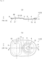
Fig. 1 illustrates a tab for opening a can lid according to an embodiment of the invention ((a) is a sectional view taken along line A-A, (b) is a plan view, and (c) is a rear view). - [
Fig. 2 ]
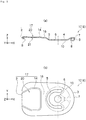
Fig. 2 illustrates a tab for opening a can lid according to another embodiment of the invention ((a) is a sectional view taken along line A-A, (b) is a plan view, and (c) is a rear view). - [
Fig. 3 ]
Fig. 3 illustrates a tab for opening a can lid according to another embodiment of the invention ((a) is a sectional view taken along line A-A, (b) is a plan view, and (c) is a rear view). - [
Fig. 4 ]
Fig. 4 illustrates a tab for opening a can lid according to another embodiment of the invention ((a) is a sectional view taken along line A-A, and (b) is a plan view). - [
Fig. 5 ]
Fig. 5 illustrates a tab for opening a can lid according to another embodiment of the invention ((a) is a sectional view taken along line A-A, and (b) is a plan view). - [
Fig. 6 ]
Fig. 6 illustrate the position of a display part in a tab for opening a can lid according to the embodiment of the invention ((a) corresponds to the example shown inFig. 1 and (b) corresponds to the example shown inFig. 3 ). - [
Fig. 7 ]
Fig. 7 is a view for illustrating a method for manufacturing a can lid to which a tab for opening the can lid is attached. - [
Fig. 8 ]
Fig. 8 is a view for illustrating a process for forming a tab for opening a can lid ((a) corresponds to a state after a display part is drawn, (b) corresponds to a state after hole machining, and (c) corresponds to a state after the outer peripheral part is blanked). - [
Fig. 9 ]
Fig. 9 illustrates a process for forming a tab for opening a can lid ((a) and (b) correspond to states after irregularity shaping and (c) is a state after curl shaping). - [
Fig. 10 ]
Fig. 10 illustrates irregularity shaping processing to a tab panel ((a) corresponds to a state before shaping and (b) corresponds to a state after shaping). - Hereinafter, embodiments of the present invention will be described with reference to the drawings. In the following description, the same reference characters among different figures indicate portions having the same functions, and their description in connection with the drawings will not be repeated as appropriate. The direction of the arrow X in
Figs. 1 to 3 indicates the longitudinal direction of the tab for opening a can lid, the direction of the arrow Y indicates the direction orthogonal to the X direction when viewed in a plan view, and the arrow Z indicates the thickness-wise direction of the tab for opening a can lid. - As shown in
Figs. 1 to 3 , the tab for opening a can lid (hereinafter as a tab) 1 (1A, 1B, or 1C) has a pulling-uppart 2 provided on one end side in the longitudinal direction (in the X direction in illustrations), a pressing-down part 3 on the other end side in the longitudinal direction (in the X direction in illustrations) and afixed part 4 between the pulling-uppart 2 and the pressing-down part 3. - A person engaged in opening operation puts a finger on the pulling-up
part 2, and the opening operation is performed by pulling up the part in the Z direction in illustrations. As the pulling-uppart 2 is pulled up, the pressing-down part 3 is pressed down in the opposite direction, and when the pressing-down part is pressed down in abutment against the panel of the can lid body, the score of the can lid is ruptured. - The
fixed part 4 is formed by being demarcated by aU-shaped slot 5 and includes arivet hole 6 through which a rivet to be provided on the panel of the can lid body is inserted, and thefixed part 4 is fixed to the can lid body as the rivet is inserted into therivet hole 6 and crimped. - A connected-piece-
cutting trace 7 is provided in the center of the pressing-down part 3. Then, acurl part 8 is formed on the outer peripheral edge of thetab 1 excluding the connected-piece-cutting trace 7. Thecurl part 8 increases the flexural rigidity of thetab 1 because thetab 1 serves as a lever having the pulling-uppart 2 as a point of effort, thefixed part 4 as a fulcrum point, and the pressing-down part 3 as a point of load. Here, the connected-piece-cutting trace 7 is provided at the pressing-down part 3, so that the interrupted part of thecurl part 8 is in a position free from bending force caused when the pulling-uppart 2 is pulled up during opening operation, and thetab 1 has rigidity necessary for opening the can lid. - The tab 1 (1A, 1B, or 1C) is shaped. In one case, a
shaped part 10 having a convex shape in the direction opposite to the Z direction is provided on the periphery of thefixed part 4, and the region between the pulling-uppart 2 and thefixed part 4 is shaped. The tab 1 (1A) shown inFig. 1 is provided with ashaped part 11 in a convex shape (i.e., shaped to have a convex shape on the surface side and a concave shape on the back surface side) in the Z direction in illustrations between the pulling-uppart 2 and thefixed part 4. The tab 1 (1B) shown inFig. 2 is provided with ashaped part 12 shaped to have a convex dome shape in the Z direction in illustrations between the pulling-uppart 2 and thefixed part 4. The tab 1 (1C) shown inFig. 3 has a region between the pulling-uppart 2 and thefixed part 4 flattened by reform shaping. - Tab 1 (1A, 1B, or 1C) includes a
display surface 20. Although not shown, thedisplay surface 20 is the surface between the pulling-uppart 2 and thefixed part 4 which is formed with a display part for example for a two-dimensional code, a logo, a picture, letters, and numbers drawn by laser marking or ink jet printing. The back surface side of thedisplay surface 20 is an abuttedsurface 21 for performing the shaping processing as described above. A shaping tool for shaping the shapedparts Fig. 3 abuts against the abuttedsurface 21. -
Figs. 4 and5 illustrate other examples (tabs 1 (1D and 1E)). The portions identical to those described above are designated by the same reference characters and their description will not be provided. The tab 1 (1D) shown inFig. 4 includes ashaped part 13 on the display surface 20 (or the abutted surface 21) between the pulling-uppart 2 and thefixed part 4 and abead shape part 15 therearound. Theshaped part 13 is formed to have a convex shape (upwardly convex shape) on the surface side, and thebead shape part 15 is shaped to have a wavy cross-section around theshaped part 13. The tab 1 (1E) shown inFig. 5 includes ashaped part 14 on the display surface 20 (or the abutted surface 21) between the pulling-uppart 2 and thefixed part 4, and a steppedpart 16 is formed between theshaped part 14 and thefixed part 4 to provide a tip upshape part 17 including the shapedpart 14, thedisplay part 20, and the pulling-uppart 2. Theshaped part 14 is formed to have a convex shape (upwardly convex shape) on the surface side, and the steppedpart 16 has a step between theshaped part 14 and thefixed part 4. -
Fig. 6 shows the positions of thedisplay part 20A on thedisplay surface 20 of thetab 1. In the example shown inFig. 6(a) , thedisplay part 20A is provided within the range of the shapedpart 11 provided at thedisplay surface 20, and in the example shown inFig. 6(b) , thedisplay part 20A is provided in a prescribed range of thedisplay surface 20 shaped to be flat. The size L1×L2 of thedisplay part 20A can be set as appropriate (for example, L1 is from 4.5 mm to 8.8 mm and L2 is from 7.0 mm to 11.6 mm). - The can lid to which the
tab 1 is attached is produced as shown inFig. 7 . In other words, a tab material T unwound from the coil C is first passed through a drawing device (for example, a laser marker) 30 and a display part drawn for example by laser marking is formed on the surface of the tab material T. Then, the tab material T having the display part formed thereon is passed through atab shaping machine 31 and formed into thetab 1. -
Figs. 8 and9 show the process for forming the tab as the tab material T is passed through thedrawing device 30 and thetab shaping machine 31.Fig. 8(a) shows a state in which the display part T1 is drawn on the surface of the tab material T. The display part T1 is formed in thedrawing device 30 shown inFig. 7 .Fig. 8(b) shows a state in which the tab material T is subjected to hole machining in thetab shaping machine 31. Here, therivet hole 6 and theU-shaped slot 5 are formed in set positions, and holes T2 and T3 for forming a connected-piece (carry point) T4 are formed. InFig. 9(c) , a cut line T5 which defines a further outer side of the outer peripheral edge of the tab is formed by blanking. -
Fig. 9(a) shows a state in which shaped parts are formed inside the cut line T5 and near therivet hole 6 and theslot 5, andFig. 9(b) shows how theshaped part 10 is formed outside theslot 5 and theshaped part 11 is formed. - As shown in
Fig. 10 , theshaped part 11 is shaped using ashaping die 40 and ashaping tool 41 provided in thetab shaping machine 31. Here, as shown inFig. 10(a) , thedisplay surface 20 having the display part T1 of the tab material T formed thereon is provided toward thedie hole 40A of the shaping die 40, so that theshaping tool 41 is provided to oppose the abuttedsurface 21 of the back surface of the tab material T. - The
shaping tool 41 is made to abut against the abuttedsurface 21 of the tab material T, and theshaping tool 41 is pressed into thedie hole 40A, so that theshaped part 11 is shaped inside thedie hole 40A as shown inFig. 10(b) . At the time, shaping is performed while keeping theshaping tool 41 in abutment against the abuttedsurface 21 on the back surface side of thedisplay surface 20, and therefore the display part T1 formed on thedisplay surface 20 can be prevented from contacting theshaping tool 41. In this way, theshaped part 11 can be shaped without disturbing the display state of the display part T1 and causing dust or ink at the display part T1 to be transferred onto theshaping tool 41. The tab 1 (1C) has the abuttedsurface 21 formed to be flat, and therefore the area of the display part T1 can be greater than that of any of the other tabs 1 (1A and 1B). - The tab material T passed through the
tab shaping machine 31 is sent to aconversion press 32 shown inFig. 7 while thetab 1 is connected to the tab material T by the connected-piece T4 as shown inFig. 9(c) . Th can lid body is shaped at theconversion press 32, therivet hole 6 of thetab 1 is positioned with respect to the position of the rivet of the can lid body, the connected-piece T4 is severed, and thetab 1 is removed from the tab material T and then the rivet is inserted into therivet hole 6 and crimped, so that thetab 1 is attached to the can lid body. In this way, the can lid P is obtained. - Table 1 gives a sensory evaluation result about opening operation according to the embodiment illustrated in
Fig. 1 (in which thedisplay surface 20 is on the surface side, the abuttedsurface 21 is on the back surface side, and the upwardly convexshaped part 11 is formed). - The sensory evaluation test about opening operation was performed, and in the test, a can lid provided with a
tab 1 according to the embodiment was designated as example 1 (the can lid provided with thetab 1 having thedisplay surface 20 on the surface side, the abuttedsurface 21 on the back surface side, and the upwardly convexshaped part 11 formed), a can lid identical to example 1 except for the flat shapedpart 11 was designated as example 2, and a can lid identical to example 1 except for the downwardly convexshaped part 11 was designated as example 3. - During opening operation in the sensory evaluation test, the finger is first inserted into the gap between the
tab 1 and the lid surface while the finger tip touches thetab 1, then the finger is guided toward the abuttedsurface 21 of thetab 1 while, at the same time, thetab 1 is lifted by the finger to initially open the can. Then, the inside of the finger is firmly pressed against the abuttedsurface 21 of thetab 1 and thetab 1 is lifted by the inside of the finger, so that the opening piece defined by the score of the can lid body is pressed down. - In the sensory evaluation test, the
tab 1 was lifted up by the inside of the finger in each of examples 1 to 3, and awkward feeling experienced when pressing down the opening piece defined by the score of the can lid body was relatively evaluated. In example 1 with the tab formed with the upwardly convexshaped part 11 or example 2 with the tab formed with the flat shapedpart 11, the distance S1 (seeFig. 1 ) from the surface of the pulling-up part on the lower surface side to the abuttedsurface 21 is greater on the upper side (in the Z direction) than that in example 3 having the downwardly convexshaped part 11, and therefore it is considered that the finger tip is easily moved on the upper side (in the Z direction) when guided to the abuttedsurface 21 of thetab 1, and the operational feeling experienced when pulling up thetab 1 improves. - In the sensory evaluation test the evaluation indexes with reference to example 3 include "⊚" which represents very good operational feeling in pulling up the tab with less awkwardness than example 3, "0" which represents good operational feeling in pulling up the tab with less awkwardness than example 3, and "Δ" which represents feeling with a little more awkwardness than example 3.
- As can be clearly understood from Table 1, in example 1 (with the upwardly convex shaped part 11) and example 2 (with the flat shaped part 11), generally good operational feeling with less awkwardness resulted than that in example 3 (with the downward convex shaped part 11). More specifically, when the display part T1 is provided on the surface side in the
tab 1 and the upwardly convexshaped part 11 is shaped while the shaping tool is abutted thereupon from the back surface side or when the part between the pulling-up part and the fixed part is shaped to be flat, the display part T1 with no disturbance as well as good operational feeling in opening operation can be obtained. The connected-piece T4 is positioned at the pressing-down part, and necessary rigidity for thetab 1 can be obtained.[Table 1] Example 1 Example 2 Example 3 Evaluator 1Δ ○ - Evaluator 2○ ○ - Evaluator 3 ○ ○ - Evaluator 4○ Δ - Evaluator 5○ ○ - Evaluator 6⊚ Δ - Evaluator 7○ ○ - Evaluator 8○ ○ - Evaluator 9 ○ ○ - - The embodiments of the present invention have been described in detail with reference to the drawings, while specific configurations are not limited by these embodiments and design changes not departing from the gist of the present invention are encompassed by the present invention. These embodiments can divert and combine their features with one another if there is no particular inconsistency or problem in relation to the purposes and structures of the features.
-
- 1 (1A, 1B, 1C)
- Tab for opening can lid (tab)
- 2
- Pulling-up part
- 3
- Pressing-down part
- 4
- Fixed part
- 5
- Slot
- 6
- Rivet hole
- 7
- Connected-piece-cutting trace
- 8
- Curl part
- 10, 11, 12, 13, 14
- Shaped part
- 15
- Bead shape part
- 16
- Stepped part
- 17
- Tip up shape part
- 20
- Display surface
- 20A
- Display part
- 21
- Abutted surface
- 30
- Drawing device
- 31
- Tab shaping machine
- 32
- Conversion press
- T
- Tab material
- T1
- Display part
- T2, T3
- Hole
- T4
- Connected-piece
- T5
- Cut line
- P
- Can lid
Claims (4)
- A tab for opening a can lid, the tab comprising:a pulling-up part provided on one end side in a longitudinal direction of the tab;a pressing-down part provided on another end side in the longitudinal direction,a fixed part provided between the pulling-up part and the pressing-down part and formed by being demarcated by a U-shaped slot and fixed to a can lid body; anda curl part formed continuously at a peripheral edge excluding a connected-piece-cutting trace provided at the pressing-down part, whereina surface between the fixed part and the pulling-up part is a display surface, and a back surface side of the display surface is an abutted surface against which a shaping tool is abutted.
- The tab for opening a can lid according to claim 1, wherein
a display part drawn by laser marking or ink jet printing is formed at the display surface, and
a shaped part shaped to have a convex shape on the display surface side and to have a concave shape on the abutted surface side is provided between the fixed part and the pulling-up part. - The tab for opening a can lid according to claim 1, wherein the abutted surface is shaped to be flat.
- A can lid comprising:the tab for opening a can lid according to any one of claims 1 to 3; anda can lid body to which the fixed part is fixed and which has an opening piece demarcated by a score which is ruptured by pressing down the pressing-down part.
Applications Claiming Priority (2)
| Application Number | Priority Date | Filing Date | Title |
|---|---|---|---|
| JP2018119888A JP7210821B2 (en) | 2018-06-25 | 2018-06-25 | Tab for can lid opening |
| PCT/JP2019/023529 WO2020004066A1 (en) | 2018-06-25 | 2019-06-13 | Tab for opening can lid |
Publications (2)
| Publication Number | Publication Date |
|---|---|
| EP3812293A1 true EP3812293A1 (en) | 2021-04-28 |
| EP3812293A4 EP3812293A4 (en) | 2022-03-09 |
Family
ID=68986444
Family Applications (1)
| Application Number | Title | Priority Date | Filing Date |
|---|---|---|---|
| EP19827267.6A Withdrawn EP3812293A4 (en) | 2018-06-25 | 2019-06-13 | LATCH TO OPEN A CAN LID |
Country Status (5)
| Country | Link |
|---|---|
| US (1) | US20210261290A1 (en) |
| EP (1) | EP3812293A4 (en) |
| JP (1) | JP7210821B2 (en) |
| CN (1) | CN112368218A (en) |
| WO (1) | WO2020004066A1 (en) |
Cited By (1)
| Publication number | Priority date | Publication date | Assignee | Title |
|---|---|---|---|---|
| US20210206186A1 (en) * | 2015-05-13 | 2021-07-08 | Crown Packaging Technology, Inc. | Marking tabs with a two dimensional code |
Families Citing this family (3)
| Publication number | Priority date | Publication date | Assignee | Title |
|---|---|---|---|---|
| JP7497598B2 (en) | 2020-03-31 | 2024-06-11 | 東洋製罐株式会社 | Can lid opening tab, can lid, and method for manufacturing the can lid opening tab |
| WO2022183054A1 (en) | 2021-02-26 | 2022-09-01 | Ball Corporation | Container with mark or markings for tracking and tracing |
| WO2026115301A1 (en) * | 2024-11-26 | 2026-06-04 | Intellectual Capital Management | Progressive die manufacturing method and associated tooling assemblies for ergonomic pull tabs |
Family Cites Families (23)
| Publication number | Priority date | Publication date | Assignee | Title |
|---|---|---|---|---|
| US4051976A (en) * | 1974-10-17 | 1977-10-04 | Walter Merton Perry | Container with attached closure |
| US4951835A (en) * | 1990-01-16 | 1990-08-28 | Demars Robert A | Beverage container opening and resealing device |
| JPH0594121U (en) * | 1992-05-23 | 1993-12-21 | 東洋製罐株式会社 | Tab for opening the lid of the can body container |
| JP3837961B2 (en) * | 1999-06-07 | 2006-10-25 | 東洋製罐株式会社 | Simple opening can lid, tab forming method and tab forming apparatus |
| KR100414528B1 (en) * | 2001-04-20 | 2004-01-07 | 주식회사 씨솔루션 | Method of manufacturing an aluminum design tab end for a beverage can |
| JP2002336925A (en) * | 2001-05-11 | 2002-11-26 | Mitsubishi Materials Corp | Method of manufacturing can opening tab |
| JP4436988B2 (en) * | 2001-05-22 | 2010-03-24 | ユニバーサル製缶株式会社 | Manufacturing method of can opening tab and manufacturing method of can lid |
| US6968724B2 (en) * | 2002-03-27 | 2005-11-29 | Metal Container Corporation | Method and apparatus for making a can lid shell |
| KR20040017006A (en) * | 2002-08-20 | 2004-02-26 | 주식회사 봉정캔텍 | Improvements in can opening tab for use in beverage can |
| MY147847A (en) * | 2003-01-15 | 2013-01-31 | Kian Joo Packaging Sdn Bhd | Can end logo stabbing system |
| US20050045637A1 (en) * | 2003-08-28 | 2005-03-03 | Rainer Rohr | Containers having distinctive tabs with laser etching and void forming a promotional image |
| US7617945B2 (en) * | 2003-09-19 | 2009-11-17 | Gabe Cherian | Pull tab |
| JP2007021564A (en) * | 2005-07-20 | 2007-02-01 | Universal Seikan Kk | Tab manufacturing method, tab and can lid |
| CN2827905Y (en) * | 2005-07-22 | 2006-10-18 | 陈国安 | Improved structure of lid of pop-top can |
| CN101445170B (en) * | 2008-11-24 | 2012-09-05 | 波尔亚太(佛山)金属容器有限公司 | Method for preparing printed lid of aluminum easy open can |
| JP5411520B2 (en) * | 2009-02-03 | 2014-02-12 | 大和製罐株式会社 | Steion tab type tab for can lid |
| US8146768B2 (en) * | 2009-02-04 | 2012-04-03 | Rexam Beverage Can Company | Tab with emboss and deboss beads |
| JP5475556B2 (en) * | 2010-06-09 | 2014-04-16 | ユニバーサル製缶株式会社 | Method for manufacturing can lid and tab |
| JP2012197103A (en) * | 2011-03-22 | 2012-10-18 | Daiwa Can Co Ltd | Tab for easy-to-open can lid |
| US20130075401A1 (en) * | 2011-09-23 | 2013-03-28 | Rexam Beverage Can Company | Stay-on tab for a beverage container |
| US9114451B2 (en) * | 2013-03-15 | 2015-08-25 | Ball Corporation | Container end closure with buckle control feature |
| JP6779043B2 (en) | 2016-01-05 | 2020-11-04 | ユニバーサル製缶株式会社 | Manufacturing method of can opening tabs, can lids, cans, and can opening tabs |
| CN107010300B (en) * | 2017-04-26 | 2018-12-28 | 珠海鼎立包装制品有限公司 | A kind of laborsaving cover of pop can equipped with two dimensional code |
-
2018
- 2018-06-25 JP JP2018119888A patent/JP7210821B2/en active Active
-
2019
- 2019-06-13 EP EP19827267.6A patent/EP3812293A4/en not_active Withdrawn
- 2019-06-13 WO PCT/JP2019/023529 patent/WO2020004066A1/en not_active Ceased
- 2019-06-13 CN CN201980041588.6A patent/CN112368218A/en active Pending
- 2019-06-13 US US17/255,325 patent/US20210261290A1/en not_active Abandoned
Cited By (1)
| Publication number | Priority date | Publication date | Assignee | Title |
|---|---|---|---|---|
| US20210206186A1 (en) * | 2015-05-13 | 2021-07-08 | Crown Packaging Technology, Inc. | Marking tabs with a two dimensional code |
Also Published As
| Publication number | Publication date |
|---|---|
| JP7210821B2 (en) | 2023-01-24 |
| CN112368218A (en) | 2021-02-12 |
| EP3812293A4 (en) | 2022-03-09 |
| US20210261290A1 (en) | 2021-08-26 |
| JP2020001710A (en) | 2020-01-09 |
| WO2020004066A1 (en) | 2020-01-02 |
Similar Documents
| Publication | Publication Date | Title |
|---|---|---|
| US20210261290A1 (en) | Tab for opening can lid | |
| CN101583541A (en) | Tab, tooling for making the tab and method of making the tab | |
| CN104955589B (en) | Manufacturing method of can lid, can lid and can body | |
| JP2017121657A (en) | Manufacturing method of tab for opening can | |
| JP7497598B2 (en) | Can lid opening tab, can lid, and method for manufacturing the can lid opening tab | |
| US3060992A (en) | Means and method for forming non-planar articles | |
| US4424698A (en) | Tool for coining | |
| JPH06154895A (en) | Drawing method by stamping | |
| JP3837961B2 (en) | Simple opening can lid, tab forming method and tab forming apparatus | |
| KR102424838B1 (en) | How to mark a witness on the tap body and tap press | |
| JP5411520B2 (en) | Steion tab type tab for can lid | |
| JP6928502B2 (en) | Can opening tab and can lid | |
| CN111278584B (en) | Method for manufacturing fastener element | |
| JPH0635019B2 (en) | Hemming method for drawing products | |
| JP6990050B2 (en) | Tabs for opening cans and can lids | |
| JP5076540B2 (en) | Embossing method and blank sheet produced thereby | |
| JP2512923B2 (en) | Bending method for punched holes in pressed products | |
| JPH02151322A (en) | Method and device for deep drawing | |
| JP2002336925A (en) | Method of manufacturing can opening tab | |
| JP2007021564A (en) | Tab manufacturing method, tab and can lid | |
| JPH06170448A (en) | Bending die | |
| JP2000317536A (en) | Press molding die equipment | |
| JP2002346673A (en) | Method for manufacturing can opening tab and method for manufacturing can lid | |
| JPS6133720A (en) | Forming method of plate component | |
| JP2002234536A (en) | Tab and manufacturing method thereof |
Legal Events
| Date | Code | Title | Description |
|---|---|---|---|
| STAA | Information on the status of an ep patent application or granted ep patent |
Free format text: STATUS: THE INTERNATIONAL PUBLICATION HAS BEEN MADE |
|
| PUAI | Public reference made under article 153(3) epc to a published international application that has entered the european phase |
Free format text: ORIGINAL CODE: 0009012 |
|
| STAA | Information on the status of an ep patent application or granted ep patent |
Free format text: STATUS: REQUEST FOR EXAMINATION WAS MADE |
|
| 17P | Request for examination filed |
Effective date: 20210120 |
|
| AK | Designated contracting states |
Kind code of ref document: A1 Designated state(s): AL AT BE BG CH CY CZ DE DK EE ES FI FR GB GR HR HU IE IS IT LI LT LU LV MC MK MT NL NO PL PT RO RS SE SI SK SM TR |
|
| AX | Request for extension of the european patent |
Extension state: BA ME |
|
| DAV | Request for validation of the european patent (deleted) | ||
| DAX | Request for extension of the european patent (deleted) | ||
| A4 | Supplementary search report drawn up and despatched |
Effective date: 20220209 |
|
| RIC1 | Information provided on ipc code assigned before grant |
Ipc: B21D 51/44 20060101ALI20220203BHEP Ipc: B65D 17/34 20060101AFI20220203BHEP |
|
| STAA | Information on the status of an ep patent application or granted ep patent |
Free format text: STATUS: EXAMINATION IS IN PROGRESS |
|
| 17Q | First examination report despatched |
Effective date: 20240405 |
|
| STAA | Information on the status of an ep patent application or granted ep patent |
Free format text: STATUS: THE APPLICATION IS DEEMED TO BE WITHDRAWN |
|
| 18D | Application deemed to be withdrawn |
Effective date: 20240806 |