EP3812272A1 - Aircraft passenger reading light - Google Patents
Aircraft passenger reading light Download PDFInfo
- Publication number
- EP3812272A1 EP3812272A1 EP19205360.1A EP19205360A EP3812272A1 EP 3812272 A1 EP3812272 A1 EP 3812272A1 EP 19205360 A EP19205360 A EP 19205360A EP 3812272 A1 EP3812272 A1 EP 3812272A1
- Authority
- EP
- European Patent Office
- Prior art keywords
- reading light
- passenger
- light sources
- aircraft
- rows
- Prior art date
- Legal status (The legal status is an assumption and is not a legal conclusion. Google has not performed a legal analysis and makes no representation as to the accuracy of the status listed.)
- Granted
Links
- 238000005286 illumination Methods 0.000 claims abstract description 31
- 238000010168 coupling process Methods 0.000 claims abstract description 12
- 238000005859 coupling reaction Methods 0.000 claims abstract description 12
- 230000008878 coupling Effects 0.000 claims abstract description 11
- 230000003287 optical effect Effects 0.000 claims description 8
- 238000001514 detection method Methods 0.000 claims description 6
- 238000000034 method Methods 0.000 claims description 5
- 238000012423 maintenance Methods 0.000 description 5
- 229920002492 poly(sulfone) Polymers 0.000 description 4
- 238000013459 approach Methods 0.000 description 2
- 238000010586 diagram Methods 0.000 description 2
- QVGXLLKOCUKJST-UHFFFAOYSA-N atomic oxygen Chemical compound [O] QVGXLLKOCUKJST-UHFFFAOYSA-N 0.000 description 1
- 230000009286 beneficial effect Effects 0.000 description 1
- 230000001419 dependent effect Effects 0.000 description 1
- 230000000694 effects Effects 0.000 description 1
- 238000009434 installation Methods 0.000 description 1
- 238000004519 manufacturing process Methods 0.000 description 1
- 239000000463 material Substances 0.000 description 1
- 239000011159 matrix material Substances 0.000 description 1
- 238000012986 modification Methods 0.000 description 1
- 230000004048 modification Effects 0.000 description 1
- 229910052760 oxygen Inorganic materials 0.000 description 1
- 239000001301 oxygen Substances 0.000 description 1
- 230000000007 visual effect Effects 0.000 description 1
Images


Classifications
-
- B—PERFORMING OPERATIONS; TRANSPORTING
- B60—VEHICLES IN GENERAL
- B60Q—ARRANGEMENT OF SIGNALLING OR LIGHTING DEVICES, THE MOUNTING OR SUPPORTING THEREOF OR CIRCUITS THEREFOR, FOR VEHICLES IN GENERAL
- B60Q3/00—Arrangement of lighting devices for vehicle interiors; Lighting devices specially adapted for vehicle interiors
- B60Q3/40—Arrangement of lighting devices for vehicle interiors; Lighting devices specially adapted for vehicle interiors specially adapted for specific vehicle types
- B60Q3/41—Arrangement of lighting devices for vehicle interiors; Lighting devices specially adapted for vehicle interiors specially adapted for specific vehicle types for mass transit vehicles, e.g. buses
- B60Q3/44—Spotlighting, e.g. reading lamps
-
- B—PERFORMING OPERATIONS; TRANSPORTING
- B60—VEHICLES IN GENERAL
- B60Q—ARRANGEMENT OF SIGNALLING OR LIGHTING DEVICES, THE MOUNTING OR SUPPORTING THEREOF OR CIRCUITS THEREFOR, FOR VEHICLES IN GENERAL
- B60Q3/00—Arrangement of lighting devices for vehicle interiors; Lighting devices specially adapted for vehicle interiors
- B60Q3/40—Arrangement of lighting devices for vehicle interiors; Lighting devices specially adapted for vehicle interiors specially adapted for specific vehicle types
- B60Q3/41—Arrangement of lighting devices for vehicle interiors; Lighting devices specially adapted for vehicle interiors specially adapted for specific vehicle types for mass transit vehicles, e.g. buses
- B60Q3/47—Circuits; Control arrangements
-
- B—PERFORMING OPERATIONS; TRANSPORTING
- B60—VEHICLES IN GENERAL
- B60Q—ARRANGEMENT OF SIGNALLING OR LIGHTING DEVICES, THE MOUNTING OR SUPPORTING THEREOF OR CIRCUITS THEREFOR, FOR VEHICLES IN GENERAL
- B60Q3/00—Arrangement of lighting devices for vehicle interiors; Lighting devices specially adapted for vehicle interiors
- B60Q3/70—Arrangement of lighting devices for vehicle interiors; Lighting devices specially adapted for vehicle interiors characterised by the purpose
- B60Q3/76—Arrangement of lighting devices for vehicle interiors; Lighting devices specially adapted for vehicle interiors characterised by the purpose for spotlighting, e.g. reading lamps
-
- B—PERFORMING OPERATIONS; TRANSPORTING
- B60—VEHICLES IN GENERAL
- B60Q—ARRANGEMENT OF SIGNALLING OR LIGHTING DEVICES, THE MOUNTING OR SUPPORTING THEREOF OR CIRCUITS THEREFOR, FOR VEHICLES IN GENERAL
- B60Q3/00—Arrangement of lighting devices for vehicle interiors; Lighting devices specially adapted for vehicle interiors
- B60Q3/80—Circuits; Control arrangements
- B60Q3/82—Switches specially adapted for vehicle interior lighting, e.g. switching by tilting the lens
-
- B—PERFORMING OPERATIONS; TRANSPORTING
- B64—AIRCRAFT; AVIATION; COSMONAUTICS
- B64D—EQUIPMENT FOR FITTING IN OR TO AIRCRAFT; FLIGHT SUITS; PARACHUTES; ARRANGEMENTS OR MOUNTING OF POWER PLANTS OR PROPULSION TRANSMISSIONS IN AIRCRAFT
- B64D11/00—Passenger or crew accommodation; Flight-deck installations not otherwise provided for
- B64D11/06—Arrangements of seats, or adaptations or details specially adapted for aircraft seats
-
- B—PERFORMING OPERATIONS; TRANSPORTING
- B64—AIRCRAFT; AVIATION; COSMONAUTICS
- B64D—EQUIPMENT FOR FITTING IN OR TO AIRCRAFT; FLIGHT SUITS; PARACHUTES; ARRANGEMENTS OR MOUNTING OF POWER PLANTS OR PROPULSION TRANSMISSIONS IN AIRCRAFT
- B64D11/00—Passenger or crew accommodation; Flight-deck installations not otherwise provided for
- B64D2011/0053—Cabin passenger reading lights
-
- B—PERFORMING OPERATIONS; TRANSPORTING
- B64—AIRCRAFT; AVIATION; COSMONAUTICS
- B64D—EQUIPMENT FOR FITTING IN OR TO AIRCRAFT; FLIGHT SUITS; PARACHUTES; ARRANGEMENTS OR MOUNTING OF POWER PLANTS OR PROPULSION TRANSMISSIONS IN AIRCRAFT
- B64D2203/00—Aircraft or airfield lights using LEDs
Definitions
- the present invention is in the field of aircraft passenger reading lights.
- the present invention is in particular related to aircraft passenger reading lights which may be employed in different types of aircraft.
- Passenger aircraft such as commercial airplanes usually have a passenger cabin comprising a plurality of passenger seats and passenger reading lights arranged above the passenger seats, in order to allow passengers sitting in the passenger seats to read even if the illumination within the passenger cabin is dimmed low or switched off.
- the aircraft passenger reading lights are adapted to the geometry of the passenger cabin of the aircraft in which they are to be installed. They are in particular adapted to the spatial relation between the aircraft passenger reading light and the passenger seat which is to be illuminated.
- aircraft passenger reading lights which may be adapted easily to different geometries of the passenger cabin, in order to allow using a single type of aircraft passenger reading light in different types of passenger cabins, in particular in passenger cabins with different passenger seat configurations.
- an aircraft passenger reading light comprises a light source arrangement having a plurality of rows of reading light sources, with each of the rows having a plurality of reading light sources for passenger-specific illumination of a plurality of seats of a seating row of an aircraft and with the plurality of rows having different illumination directions in a longitudinal direction of the aircraft.
- Each of the plurality of reading light sources comprises a first electrical terminal and a second electrical terminal.
- the aircraft passenger reading light further comprises a first power supply connector and a second power supply connector for coupling the aircraft passenger reading light to an aircraft on-board power supply; and a multi-state switching arrangement having a plurality of switching states.
- the first power supply connector is coupled to the first electrical terminals of the plurality of reading light sources
- the second power supply connector is coupled to the second electrical terminals of the plurality of reading light sources via the multi-state switching arrangement.
- Each of the plurality of switching states permanently couples the second electrical terminals of the reading light sources of a single one of the plurality of rows to the second power supply connector and permanently de-couples the second electrical terminals of the reading light sources of the other rows from the second power supply connector.
- Exemplary embodiments of the invention also include a method of configuring an aircraft passenger reading light according to an exemplary embodiment of the invention, wherein the method includes establishing a permanent coupling configuration between the second power supply connector and the second electrical terminals of the plurality of reading light sources via selecting a particular one of the plurality of switching states of the multi-state switching arrangement.
- Each of the plurality of switching states permanently couples the second electrical terminals of the reading light sources of a single one of the plurality of rows to the second power supply connector and permanently de-couples the second electrical terminals of the reading light sources of the other rows from the second power supply connector.
- the light emission provided by the aircraft passenger reading light may be modified and adjusted to different geometries within the passenger cabin.
- the light emission provided by the aircraft passenger reading light may in particular be adjusted to different seat configurations within the passenger cabin, in particular to different distances between adjacent rows of passenger seats.
- the same type of aircraft passenger reading light may be employed in combination with a plurality of different passenger cabin configurations.
- a single type of aircraft passenger reading light may be produced in large numbers and be installed in different types of aircraft. As a result, the production costs for each aircraft passenger reading light may be reduced, as compared to a situation in which individual types of aircraft passenger reading lights need to be produced for ever type of passenger cabin configuration.
- the switching state of the multi-state switching arrangement may be set or changed only before the aircraft passenger reading light is installed within the passenger cabin of an aircraft or after the reading light has been de-installed from the passenger cabin or in specialized maintenance procedures.
- the switching state of the multi-state switching arrangement may be set or changed only in the factory, when the aircraft is assembled, or during maintenance of the aircraft, in particular when the configuration of the passenger cabin in modified.
- the switching state of the multi-state switching arrangement cannot be changed by passengers or the aircraft crew, as long as the aircraft passenger reading light is installed within the aircraft cabin. This prevents the aircraft passenger reading light from being switched accidentally into a state which does not correspond to the actual configuration of the passenger cabin.
- a switching tool such as a screwdriver or a specifically designed switching tool, may be necessary for changing the switching state of the multi-state switching arrangement. Such a switching tool may be available only in the factory and/or the hangar where the aircraft is assembled and/or maintained.
- the expression of the second electrical terminals of the reading light sources of a single one of the plurality of rows being permanently coupled to the second power supply connector does not require an ongoing current flow through the reading light sources of said single one of the plurality of rows. Rather, it means that a permanent circuit configuration is established that generally enables current flow through the reading light sources of said one row, which current flow may for example be additionally dependent on the passenger-specific illumination commands, as will be explained in more details below.
- the second terminals of the reading light sources of the other rows being permanently de-coupled from the second power supply connector means that a current flow through those reading light sources is not possible in regular operation of the aircraft.
- neither the passenger nor the crew nor any on-board control instance can effect power flow through the reading light sources of said other rows in regular operation of the aircraft.
- a re-configuration of the multi-state switching arrangement would be required for coupling a different row of reading light sources to the second power supply connector.
- An aircraft passenger reading light does in particular not comprise a seat position detection sensor or a seat position detection system, which is configured for detecting the current position of the passenger seat while the aircraft is operated.
- the switching state of the multi-state switching arrangement is set permanently, as it has been discussed before. The switching state is in particular not changed when the passenger seat, in particular the back rest of the passenger seat, is moved by a passenger in flight. Thus, there is no reason for providing a seat position detection sensor or a seat position detection system, detecting the current position of the passenger seat.
- the number of reading light sources in each row of reading light sources corresponds to the number of seats to be illuminated by a single aircraft passenger reading light.
- the number of reading light sources in each row may be two, three, four or five, corresponding to two, three, four or five passenger seats arranged next to each other in a single row, respectively.
- Such a configuration allows for illuminating all passenger seats arranged next to each other within a single row, i.e. all passengers seats between the outer wall of the passenger cabin and an aisle or all passenger seats between two aisles, with a single aircraft passenger reading light. In consequence, a small number of passenger reading lights is needed.
- the single aircraft passenger reading light further comprises a plurality of passenger command input terminals for receiving passenger-specific illumination commands.
- Each passenger command input terminal is functionally coupled to at least one associated reading light source per row of reading light sources.
- the power flow through the reading light sources depends on the switching state of the multi-state switching arrangement and the passenger-specific illumination commands.
- the at least one associated reading light source may be a single light source or a group of light sources, in particular a group of light sources arranged next to each other.
- the passenger-specific illumination commands establish or interrupt an electrical connection between the first power supply connector and the second power supply connector through the associated reading light source within the row of reading light sources "activated" by the multi-state switching arrangement.
- the associated at least one reading light source is addressed by the particular illumination command, in order to selectively activate or deactivate the at least one associated reading light source.
- the multi-state switching arrangement comprises a multi-way mechanical switch or a plug-connector, which is configured for selecting a particular one of the plurality of switching states.
- a multi-way mechanical switch and a plug-connector provide reliable multi-state switching arrangements which may be realized with low complexity and at low costs.
- the multi-state switching arrangement comprises at least one signal input terminal which allows selecting the switching state of the multi-state switching arrangement by delivering an appropriate control signal to the at least one signal input terminal.
- the multi-state switching arrangement may in particular be an electromechanical and/or electronic multi-state switching arrangement.
- the control signal is provided by an appropriate set-up tool, which is electrically connected to the at least one signal input terminal.
- the reading light sources are arranged on a common mounting plane.
- the plurality of rows of reading light sources may in particular be arranged on a common circuit board, for example on a common printed circuit board.
- Such a configuration allows for an easy assembly and installation of the reading light sources.
- the reading light sources may in particular be soldered to the circuit board for providing the necessary electrical connections.
- the aircraft passenger reading light further comprises a common optical system, in particular a common lens, which is arranged over the plurality of rows of reading light sources, i.e. on the side of the reading light sources opposite to the common mounting plane, so that the light emitted by the plurality of reading light sources passes though the optical system.
- the common optical system is arranged below the reading light sources, in particular between the reading light sources and the passenger seats.
- the common optical system modifies the light emitted by the reading light sources, it in particular focuses the light emitted by the reading light sources, in order to provide a convenient illumination to the passengers sitting on the passenger seats and using the aircraft passenger reading light.
- the plurality of rows of reading light sources are spaced apart in the longitudinal direction of the aircraft.
- the different illumination directions of the plurality of rows of reading light sources in particular correspond to distances of between 20 cm and 40 cm on a seat pan height of the seating row of the aircraft. This allows adjusting the illumination provided by the aircraft passenger reading light to different distances between adjacent seat rows.
- the plurality of rows of reading light sources are three rows of reading light sources.
- Three rows of reading light sources provide a good compromise between the range, in which the illumination provided by the aircraft passenger reading light may be adjusted, and the complexity of the aircraft passenger reading light.
- the aircraft passenger reading light may comprise more, e.g. four or five, or fewer, i.e. two, rows of reading light sources.
- each of the reading light sources is an LED or comprises one or more LEDs, such as a group of LEDs, respectively. LEDs provide reliable and efficient light sources at low costs.
- Exemplary embodiments of the invention further include an aircraft with a passenger cabin, comprising a plurality of passenger seats and a plurality of aircraft passenger reading lights, as described in any of the embodiments above, arranged above the passenger seats.
- the plurality of passenger seats are arranged in a plurality of rows and the second power supply connector of each aircraft passenger reading light is coupled to the second terminals of the reading light sources of only a single row of reading light sources, in order to select the reading light sources of this row as the only reading light sources to be switched on when the aircraft passenger reading light is operated.
- the row of reading light sources coupled to the second power supply connector, is selected based on the distance between the respective aircraft passenger reading light and an associated row of passenger seats in the longitudinal direction, in order to adjust the characteristics of the light emitted by the aircraft passenger reading light to the distance between the respective aircraft passenger reading light and an associated row of passenger seats for providing a convenient illumination to the passengers.
- each row of reading light sources comprises a plurality of reading light sources and each of said reading light sources is associated with one of the seats of an associated row of passengers seats, in order to act as a reading light for the respectively associated passenger seat.
- Figure 1 shows a schematic side view of an aircraft 100 with a passenger cabin 102.
- Figure 2A shows a longitudinal cross-sectional view of a portion of the passenger cabin 102 of the aircraft 100.
- Figure 2B shows a partial cross-sectional view of the passenger cabin 102 in a plane which is oriented orthogonally to the longitudinal direction L.
- Each of the depicted passenger seats 80a belongs to a different seating row 80.
- Each seating row 80 includes three passenger seats 80a, 80b, 80c (see Figure 2B ).
- the second and third passenger seats 80b, 80c are not visible in Figure 2A , as they are arranged behind and therefore hidden by the depicted first passenger seats 80a.
- a window 108 is provided, which allows the passengers to view the outside of the aircraft 100. Further, a plurality of overhead baggage compartments 112 are shown, which provide storage space for baggage.
- Each of the passenger seats 80a has a seat back (backrest) 82, a seat pan 84, a seat base 86, and an arm rest 87.
- the arm rest 87 may be pivotable around a horizontal axis.
- the seat base 86 supports the seat back 82 and the seat pan 84.
- a passenger service unit (PSU) 120 is arranged above each of the seat rows 80, respectively.
- Each PSU 120 may comprise gaspers, loudspeakers, emergency oxygen masks and service call buttons, which are not shown in Figures 2A and 2B .
- Each PSU 120 further comprises at least one switchable aircraft passenger reading light 2, providing individual reading illumination for each passenger sitting in one of the passenger seats 80a-80c, in order to allow the passengers to read even if the cabin light is dimmed down or switched-off.
- the distance a between the rows 80 of passenger seats 80a-80c in the longitudinal direction L of the passenger cabin 102 may be different, depending on the demands of the airline operating the respective aircraft 100.
- the rows 80 may be arranged in small distances a, in order to maximize the number of passengers fitting into the passenger cabin 102, when the aircraft is operated by a low cost airline.
- the distances a between the rows 80 of passenger seats 80a-80c may be set larger, in order to provide more comfort to the passengers, when the aircraft is operated by a premium airline.
- the light outputs of the aircraft passenger reading lights 2 are adjusted to the positions of the passenger seats 80a-80c.
- the possible positions of the PSUs 120 and thus the positions of the reading lights 2 being part of the PSUs 120 in the longitudinal direction L may be restricted by the ceiling structure of the passenger cabin 102.
- the ceiling structure may in particular not allow positioning the PSUs 120 at arbitrary positions along the longitudinal direction L, but only at a restricted number of predetermined positions.
- different types of reading lights 2 having different light emission characteristics have been used.
- different types of reading lights 2 have been used for providing convenient reading illumination for each of the different passenger seats 80a-80c in each seating row 80.
- the PSUs 120 have been moved and/or the reading lights have been replaced with different types of reading lights in prior approaches.
- an aircraft passenger reading light 2 comprises a plurality of reading light sources 6 arranged in a plurality of rows 61, 62, 63, wherein each of the rows 61, 62, 63 corresponds to a different distance a between adjacent rows 80 of passenger seats 80a-80c.
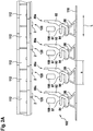
- Figure 3 depicts a cross-sectional view of an exemplary embodiment of such an aircraft passenger reading light 2.
- the cross-sectional plane is oriented basically horizontally, i.e. parallel to the floor 110 of the passenger cabin 102 when the aircraft passenger reading light 2 is installed within the passenger cabin 102 above the passenger seats 80a-80c, as it is depicted in Figures 2A and 2B .
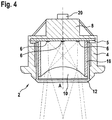
- Figure 4 depicts a cross-sectional view of the aircraft passenger reading light 2 shown in Figure 3 , wherein the cross-sectional plane is oriented vertically, i.e. orthogonally to the cross-sectional plane of Figure 3 .
- the aircraft passenger reading light 2 has a cylindrical housing 4 extending with a diameter D of, for example, 40 mm to 50 mm, in particular a diameter D of 45 mm, around a central axis A.
- the central axis A is oriented basically vertically, i.e. orthogonally to the floor 110.
- the circuit board 5 extends basically orthogonally to the central axis A and supports a plurality of reading light sources 6.
- the reading light sources 6 are arranged in a rectangular matrix configuration, comprising three rows 61, 62, 63 and three columns 6a, 6b, 6c, respectively.
- the distance d1 between the rows 61, 62, 63 may be in the range from 2 mm to 5 mm, it in particular may be 3 mm; and the distance d2 between the columns 6a, 6b, 6c may be in the range from 9 mm to 15 mm, it in particular may be 11 mm.
- Each of the columns 6a, 6b, 6c is associated with one of the passenger seats 80a-80c in each seating row 80; i.e. in an exemplary configuration, the reading light sources 6 in the first column 6a are configured for providing reading illumination 60a for an aisle seat 80a, the reading light sources 6 in the second column 6b are configured for providing reading illumination 60b for a middle seat 80b, and the reading light sources 6 in the third column 6c are configured for providing reading illumination 60c for a window seat 80c (cf. Figure 2B ).
- each of the rows 61, 62, 63 of reading light sources 6 is associated with a different distance in the longitudinal direction L between the aircraft passenger reading light 2 and the corresponding seating row 80, corresponding to a different distance a between adjacent rows 80 of passengers seats 80a-80c.
- Providing a plurality of rows 61, 62, 63 of reading light sources 6 allows for using the same aircraft passenger reading light 2 for different passenger seat arrangements. It in particular allows for using the same aircraft passenger reading light 2 in combination with passenger seat arrangements having different distances a between adjacent rows 80 of passenger seats 80a-80c. This feature will be discussed in more detail further below.
- the different rows 61, 62, 63 of reading light sources 6 may allow for using the same aircraft passenger reading light 2 in cases where the mounting position of the PSU is constrained to somewhat in front of or somewhat behind the seating row in the longitudinal direction L of the aircraft. Further, the different rows 61, 62, 63 of reading light sources 6 may allow for leaving the aircraft passenger reading light 2 in the same position, when the seating rows are re-arranged at some point during the life cycle of the aircraft, thus keeping the re-configuration efforts low.
- a heat sink 8 which is configured for dissipating the heat generated by operating the reading light sources 6, is mounted to the circuit board 5.
- the heat sink 8 is in particular attached to a rear side of the circuit board 5, i.e. to the side opposite to the reading light sources 6.
- An optical system 10, including at least one optical lens, is arranged within the path of light emitted by the reading light sources 6.
- a transparent cover 12 closes the housing 4, but allows the light emitted by the reading light sources 6 to pass through.
- the exemplary embodiment of the aircraft passenger reading light 2 depicted in Figures 3 and 4 further comprises a plurality of, in particular four, optional ambient light sources 14.
- the ambient light sources 14 are arranged outside the reading light sources 6, i.e. at a larger distance from the central axis A of the circuit board 5 than the reading light sources 6.
- four ambient light sources 14 are arranged in equal angular distances of 90° on a virtual circle C, centered around the central axis A of the circuit board 5.
- a cylindrical shutter 16 is arranged between the reading light sources 6 and the ambient light sources 14, separating light emitted by the reading light sources 6 from light emitted by the ambient light sources 14.
- the shutter 16 further prevents the light, emitted by the ambient light sources 14, from passing through the optical system 10.
- the ambient light sources 14 are controlled independently of the reading light sources 6 and allow using the aircraft passenger reading light 2 for providing ambient illumination within the passenger cabin 102.
- the ambient light sources 14 may also be used for additional functionality of the aircraft passenger reading light 2, such as for implementing a visual crew call signal.
- the ambient light sources 14 are optional and do not necessarily need to be included in aircraft passenger reading lights 2 according to exemplary embodiments of the invention.
- An aircraft passenger reading light 2 further comprises a multi-stage switching arrangement 20.
- the multi-stage switching arrangement 20 allows for configuring the aircraft passenger reading light 2 to selectively operate only one of the plurality of rows 61, 62, 63 of reading light sources 6, e.g. depending on the distances a between adjacent rows 80 of passenger seats 80a-80c in the longitudinal direction L.
- the multi-stage switching arrangement 20 may be arranged on the circuit board 5, or may be arranged entirely or in part outside the housing 4, as exemplarily depicted in Figure 4 .
- Figure 5 shows a schematic circuit diagram of an aircraft passenger reading light 2 according to an exemplary embodiment of the invention.
- the aircraft passenger reading light 2 comprise a first power supply connector 22 and a second power supply connector 24 which are configured for being connected with an electrical aircraft on-board power supply 21 of the aircraft 100.
- Each of the reading light sources 6 comprises a first electrical terminal 7 and a second electrical terminal 9, respectively.
- the first electrical terminals 7 of all reading light sources 6 are electrically connected to the first power supply connector 22.
- the second electrical terminals 9 of the reading light sources 6 are connected to the second power supply connector 24 via the multi-stage switching arrangement 20.
- the multi-stage switching arrangement 20 is configured for selectively connecting only the second electrical terminals 9 of the reading light sources 6 of a selected single row 61, 62, 62 of reading light sources 6 electrically with the second power supply connector 24.
- This selection of a single row 61, 62, 62 of reading light sources 6 is done before or at the time the aircraft passenger reading light 2 is installed within the passenger cabin 102 of the aircraft 100.
- the single one of the rows 61, 62, 62 of reading light sources 6 is selected in dependence of the position of the aircraft passenger reading light 2 with respect to the associated seating row 80.
- the selection is in particular made in dependence of the distance between the aircraft passenger reading light 2 and the associated seating row 80 in the longitudinal direction L of the passenger cabin 102, in order to provide an optimized illumination of the associated passenger seats 80a-80c.
- Figure 6 schematically shows three light cones 31, 32, 33, which are emitted by the reading light sources 6 of the respective rows 61, 62, 63 of the aircraft passenger reading light 2 according to an exemplary embodiment of the invention.
- all three light cones 31, 32, 33 are shown in Figure 6 .
- the reading light source 6 generating one of the light cones 31, 32, 33, in particular the light cone 31, 32, 33 providing the best illumination for the respective configuration of passenger seats 80a-80c, will be activated. I.e., only one of the light cones 31, 32, 33 will be generated, when the aircraft passenger reading light 2 is installed and operated within the passenger cabin 102 of an aircraft 100.
- the multi-state switching arrangement 20 is configured for permanently coupling the second power supply connector 22 of the aircraft passenger reading light 2 to the second electrical terminals 9 of the reading light sources 6 of the selected row 61, 62, 63 of reading light sources 6.
- "permanently coupling” means that the selected connections are established once before or when the aircraft passenger reading lights 2 are installed in the passenger cabin 102 of the aircraft 100 and that they are usually not changed after the aircraft passenger reading lights 2 have been installed in the passenger cabin 102.
- the selected connections in particular cannot be changed by passengers and/or the crew of the aircraft 100 during normal operation of the aircraft 100.
- the established connections may be changed during maintenance of the aircraft 100, in particular when the seat configuration within the passenger cabin 102 is changed, resulting in different distances between the aircraft passenger reading lights 2 and the associated passenger seats 80a-80c in the longitudinal direction of the aircraft.
- the multi-state switching arrangement 20 may include a mechanical switch or a plurality of mechanical switches, which is/are switchable before or when the aircraft passenger reading light 2 is installed within the passenger cabin 102, but which is/are not readily accessible after the aircraft passenger reading light 2 has been installed within the passenger cabin 102.
- the mechanical switch(es) in particular may be operable only with the assistance of an appropriate switching tool, such as a screwdriver or a specific switching tool, similar to a key, which is specifically designed for switching the mechanical switch(es).
- the multi-state switching arrangement 20 may comprise a plurality of pins 23, electrically connected with the second electrical terminals 9 and the second power supply connector 24, respectively, and at least one plugable electrical plug-connector ("jumper") 25, which is configured to be put onto two adjacent pins 23 for providing an electrical connecting between these two pins 23.
- the multi-state switching arrangement 20 may be an electrically switchable multi-state switching arrangement 20, in particular an electromechanical and/or electronic multi-state switching arrangement 20, which may be switched into the desired configuration by applying an appropriate control signal ("configuration signal") to the multi-state switching arrangement 20 before or when the aircraft passenger reading light 2 is installed within the passenger cabin 102.
- configuration signal an appropriate control signal
- Said configuration signal may be provided by an appropriate set-up tool, which is available in the factory and during maintenance of the aircraft 100, but not in the course of normal operation of the aircraft 100.
- the configuration of the multi-state switching arrangement 20 may be set and changed only in the factory and/or during maintenance/reconfiguration of the aircraft 100.
- the aircraft passenger reading light 2 further comprises a plurality of switching devices 26a, 26b, 26c, which allow selectively switching the individual reading light sources 6 of the selected row 61, 62, 63 of reading light sources 6.
- a switching device 26a, 26b, 26c is associated with each of the columns 6a, 6b, 6c of reading light sources 6, respectively.
- the reading light sources 6 of each column 6a, 6b, 6c may be switched on and off by operating the respectively associated switching device 26a, 26b, 26c.
- Each switching device 26a, 26b, 26c comprises a passenger command input terminal 28a, 28b, 28c for receiving an input command from a passenger switch 30a, 30b, 30c associated with the respective passenger seat 80a, 80b, 80c.
- the passenger switches 30a, 30b, 30c may be located next to the aircraft passenger reading light 2 within the PSU 120 above the passenger seats 80a, 80b, 80c, or in the armrests 87 of the respective passenger seat 80a, 80b, 80c, or on a touch screen on the back side of a passenger seat in front of the respective passenger seat 80a, 80b, 80c, or in any other location that is conveniently accessible for the passenger.
- the reading light sources 6 are controlled by the multi-state switching arrangement 20 in combination with the passenger switches 30a, 30b, 30c as follows: Before or when the aircraft passenger reading light 2 is installed within the passenger cabin 102 of the aircraft 100, one of the rows 61, 62, 63 of reading light sources 6 is selected by configuring the multi-state switching arrangement 20, so that it couples only the second electrical terminals 9 of the reading light sources 6 of a single one of the rows 61, 62, 63 with the second power supply connector 24. The configuration of the multi-state switching arrangement 20 remains in this established configuration, after the aircraft passenger reading light 2 has been installed within the passenger cabin 102 of the aircraft 100.
- the columns 6a, 6b, 6c of the arrangement of reading light sources 6 correspond to the different passenger seats 80a, 80b, 80c within a single seating row 80.
- the reading light sources 6 of the previously selected row 61, 62, 63 of reading light sources 6 may be selectively and individually switched on and off by the passengers by operating the corresponding passenger switches 30a, 30b, 30c. Every passenger controls only the reading light sources 6 arranged in the column 6a, 6b, 6c associated with his/her passenger seat 80a, 80b, 80c.
- Aircraft passenger reading lights 2 may be adjusted to different longitudinal distances between the aircraft passenger reading lights 2 and the associated passenger seats 80 by setting the multi-state switching arrangement 20 appropriately.
- aircraft passenger reading lights 2 according to exemplary embodiments of the invention may be adjusted to different distances between adjacent rows of passenger seats 80 within a passenger cabin 102 of an aircraft 100, without having to change the positions of the aircraft passenger reading lights 2.
- the same type of aircraft passenger reading lights 2 may be employed in different types of passenger cabins 102, so that the number of different types of aircraft passenger reading lights 2, which need to be produced, may be reduced.
- the same type of aircraft passenger reading lights 2 may be produced in large numbers at low costs.
- re-configurations of the seating layout of aircraft cabins may be made without having to change the positions of the aircraft passenger reading lights 2.
Abstract
Description
- The present invention is in the field of aircraft passenger reading lights. The present invention is in particular related to aircraft passenger reading lights which may be employed in different types of aircraft.
- Passenger aircraft, such as commercial airplanes, usually have a passenger cabin comprising a plurality of passenger seats and passenger reading lights arranged above the passenger seats, in order to allow passengers sitting in the passenger seats to read even if the illumination within the passenger cabin is dimmed low or switched off.
- In order to provide a convenient illumination to the passengers, the aircraft passenger reading lights are adapted to the geometry of the passenger cabin of the aircraft in which they are to be installed. They are in particular adapted to the spatial relation between the aircraft passenger reading light and the passenger seat which is to be illuminated.
- It would be beneficial to provide aircraft passenger reading lights which may be adapted easily to different geometries of the passenger cabin, in order to allow using a single type of aircraft passenger reading light in different types of passenger cabins, in particular in passenger cabins with different passenger seat configurations.
- According to an exemplary embodiment of the invention, an aircraft passenger reading light comprises a light source arrangement having a plurality of rows of reading light sources, with each of the rows having a plurality of reading light sources for passenger-specific illumination of a plurality of seats of a seating row of an aircraft and with the plurality of rows having different illumination directions in a longitudinal direction of the aircraft. Each of the plurality of reading light sources comprises a first electrical terminal and a second electrical terminal. The aircraft passenger reading light further comprises a first power supply connector and a second power supply connector for coupling the aircraft passenger reading light to an aircraft on-board power supply; and a multi-state switching arrangement having a plurality of switching states. The first power supply connector is coupled to the first electrical terminals of the plurality of reading light sources, and the second power supply connector is coupled to the second electrical terminals of the plurality of reading light sources via the multi-state switching arrangement. Each of the plurality of switching states permanently couples the second electrical terminals of the reading light sources of a single one of the plurality of rows to the second power supply connector and permanently de-couples the second electrical terminals of the reading light sources of the other rows from the second power supply connector.
- Exemplary embodiments of the invention also include a method of configuring an aircraft passenger reading light according to an exemplary embodiment of the invention, wherein the method includes establishing a permanent coupling configuration between the second power supply connector and the second electrical terminals of the plurality of reading light sources via selecting a particular one of the plurality of switching states of the multi-state switching arrangement. Each of the plurality of switching states permanently couples the second electrical terminals of the reading light sources of a single one of the plurality of rows to the second power supply connector and permanently de-couples the second electrical terminals of the reading light sources of the other rows from the second power supply connector.
- By coupling only the reading light sources of a single one of the plurality of rows to the second power supply connector, the light emission provided by the aircraft passenger reading light may be modified and adjusted to different geometries within the passenger cabin. The light emission provided by the aircraft passenger reading light may in particular be adjusted to different seat configurations within the passenger cabin, in particular to different distances between adjacent rows of passenger seats. Thus, the same type of aircraft passenger reading light may be employed in combination with a plurality of different passenger cabin configurations. A single type of aircraft passenger reading light may be produced in large numbers and be installed in different types of aircraft. As a result, the production costs for each aircraft passenger reading light may be reduced, as compared to a situation in which individual types of aircraft passenger reading lights need to be produced for ever type of passenger cabin configuration.
- The switching state of the multi-state switching arrangement may be set or changed only before the aircraft passenger reading light is installed within the passenger cabin of an aircraft or after the reading light has been de-installed from the passenger cabin or in specialized maintenance procedures. Thus, the switching state of the multi-state switching arrangement may be set or changed only in the factory, when the aircraft is assembled, or during maintenance of the aircraft, in particular when the configuration of the passenger cabin in modified. The switching state of the multi-state switching arrangement cannot be changed by passengers or the aircraft crew, as long as the aircraft passenger reading light is installed within the aircraft cabin. This prevents the aircraft passenger reading light from being switched accidentally into a state which does not correspond to the actual configuration of the passenger cabin. A switching tool, such as a screwdriver or a specifically designed switching tool, may be necessary for changing the switching state of the multi-state switching arrangement. Such a switching tool may be available only in the factory and/or the hangar where the aircraft is assembled and/or maintained.
- The expression of the second electrical terminals of the reading light sources of a single one of the plurality of rows being permanently coupled to the second power supply connector does not require an ongoing current flow through the reading light sources of said single one of the plurality of rows. Rather, it means that a permanent circuit configuration is established that generally enables current flow through the reading light sources of said one row, which current flow may for example be additionally dependent on the passenger-specific illumination commands, as will be explained in more details below. The second terminals of the reading light sources of the other rows being permanently de-coupled from the second power supply connector means that a current flow through those reading light sources is not possible in regular operation of the aircraft. In particular, neither the passenger nor the crew nor any on-board control instance can effect power flow through the reading light sources of said other rows in regular operation of the aircraft. As discussed above, a re-configuration of the multi-state switching arrangement would be required for coupling a different row of reading light sources to the second power supply connector.
- An aircraft passenger reading light according to an exemplary embodiment of the invention does in particular not comprise a seat position detection sensor or a seat position detection system, which is configured for detecting the current position of the passenger seat while the aircraft is operated. According to exemplary embodiments of the present invention, the switching state of the multi-state switching arrangement is set permanently, as it has been discussed before. The switching state is in particular not changed when the passenger seat, in particular the back rest of the passenger seat, is moved by a passenger in flight. Thus, there is no reason for providing a seat position detection sensor or a seat position detection system, detecting the current position of the passenger seat.
- In an embodiment, the number of reading light sources in each row of reading light sources corresponds to the number of seats to be illuminated by a single aircraft passenger reading light. In particular, the number of reading light sources in each row may be two, three, four or five, corresponding to two, three, four or five passenger seats arranged next to each other in a single row, respectively. Such a configuration allows for illuminating all passenger seats arranged next to each other within a single row, i.e. all passengers seats between the outer wall of the passenger cabin and an aisle or all passenger seats between two aisles, with a single aircraft passenger reading light. In consequence, a small number of passenger reading lights is needed.
- In an embodiment, the single aircraft passenger reading light further comprises a plurality of passenger command input terminals for receiving passenger-specific illumination commands. Each passenger command input terminal is functionally coupled to at least one associated reading light source per row of reading light sources. The power flow through the reading light sources depends on the switching state of the multi-state switching arrangement and the passenger-specific illumination commands. Such a configuration allows each passenger to switch the associated aircraft passenger reading light on and off according to his/her individual demands.
- The at least one associated reading light source may be a single light source or a group of light sources, in particular a group of light sources arranged next to each other.
- In an embodiment, the passenger-specific illumination commands establish or interrupt an electrical connection between the first power supply connector and the second power supply connector through the associated reading light source within the row of reading light sources "activated" by the multi-state switching arrangement. The associated at least one reading light source is addressed by the particular illumination command, in order to selectively activate or deactivate the at least one associated reading light source.
- In an embodiment, the multi-state switching arrangement comprises a multi-way mechanical switch or a plug-connector, which is configured for selecting a particular one of the plurality of switching states. A multi-way mechanical switch and a plug-connector provide reliable multi-state switching arrangements which may be realized with low complexity and at low costs.
- In an embodiment, the multi-state switching arrangement comprises at least one signal input terminal which allows selecting the switching state of the multi-state switching arrangement by delivering an appropriate control signal to the at least one signal input terminal. The multi-state switching arrangement may in particular be an electromechanical and/or electronic multi-state switching arrangement. In an embodiment, the control signal is provided by an appropriate set-up tool, which is electrically connected to the at least one signal input terminal.
- In an embodiment, the reading light sources are arranged on a common mounting plane. The plurality of rows of reading light sources may in particular be arranged on a common circuit board, for example on a common printed circuit board. Such a configuration allows for an easy assembly and installation of the reading light sources. The reading light sources may in particular be soldered to the circuit board for providing the necessary electrical connections.
- In an embodiment, the aircraft passenger reading light further comprises a common optical system, in particular a common lens, which is arranged over the plurality of rows of reading light sources, i.e. on the side of the reading light sources opposite to the common mounting plane, so that the light emitted by the plurality of reading light sources passes though the optical system. When the aircraft passenger reading light is installed above the passenger seats within the passenger cabin of an aircraft, the common optical system is arranged below the reading light sources, in particular between the reading light sources and the passenger seats. The common optical system modifies the light emitted by the reading light sources, it in particular focuses the light emitted by the reading light sources, in order to provide a convenient illumination to the passengers sitting on the passenger seats and using the aircraft passenger reading light.
- In an embodiment, the plurality of rows of reading light sources are spaced apart in the longitudinal direction of the aircraft. The different illumination directions of the plurality of rows of reading light sources in particular correspond to distances of between 20 cm and 40 cm on a seat pan height of the seating row of the aircraft. This allows adjusting the illumination provided by the aircraft passenger reading light to different distances between adjacent seat rows.
- In an embodiment, the plurality of rows of reading light sources are three rows of reading light sources. Three rows of reading light sources provide a good compromise between the range, in which the illumination provided by the aircraft passenger reading light may be adjusted, and the complexity of the aircraft passenger reading light. Depending on the individual circumstances, the aircraft passenger reading light may comprise more, e.g. four or five, or fewer, i.e. two, rows of reading light sources.
- In an embodiment, each of the reading light sources is an LED or comprises one or more LEDs, such as a group of LEDs, respectively. LEDs provide reliable and efficient light sources at low costs.
- Exemplary embodiments of the invention further include an aircraft with a passenger cabin, comprising a plurality of passenger seats and a plurality of aircraft passenger reading lights, as described in any of the embodiments above, arranged above the passenger seats.
- In an embodiment, the plurality of passenger seats are arranged in a plurality of rows and the second power supply connector of each aircraft passenger reading light is coupled to the second terminals of the reading light sources of only a single row of reading light sources, in order to select the reading light sources of this row as the only reading light sources to be switched on when the aircraft passenger reading light is operated.
- In an embodiment, the row of reading light sources, coupled to the second power supply connector, is selected based on the distance between the respective aircraft passenger reading light and an associated row of passenger seats in the longitudinal direction, in order to adjust the characteristics of the light emitted by the aircraft passenger reading light to the distance between the respective aircraft passenger reading light and an associated row of passenger seats for providing a convenient illumination to the passengers.
- In an embodiment, each row of reading light sources comprises a plurality of reading light sources and each of said reading light sources is associated with one of the seats of an associated row of passengers seats, in order to act as a reading light for the respectively associated passenger seat. Such a configuration allows illuminating multiple passenger seats arranged in a common row using only a single aircraft passenger reading light.
- Further exemplary embodiments of the invention will be described with respect to the accompanying drawings, wherein:
-
Figure 1 shows a schematic side view of an aircraft in accordance with an exemplary embodiment of the invention having a passenger cabin. -
Figure 2A shows a longitudinal cross-sectional view of a portion of the passenger cabin of the aircraft shown inFigure 1 . -
Figure 2B shows a lateral cross-sectional view of a portion of the passenger cabin of the aircraft shown inFigure 1 . -
Figure 3 shows a cross-sectional view of an aircraft passenger reading light according to an exemplary embodiment of the invention. -
Figure 4 shows another cross-sectional view of the aircraft passenger reading light shown inFigure 3 . -
Figure 5 shows a schematic circuit diagram of an aircraft passenger reading light according to an exemplary embodiment of the invention. -
Figure 6 schematically shows a cross-sectional view through the passenger cabin with three light cones emitted by an aircraft passenger reading light according to an exemplary embodiment of the invention. -
Figure 1 shows a schematic side view of an aircraft 100 with apassenger cabin 102. -
Figure 2A shows a longitudinal cross-sectional view of a portion of thepassenger cabin 102 of the aircraft 100.Figure 2B shows a partial cross-sectional view of thepassenger cabin 102 in a plane which is oriented orthogonally to the longitudinal direction L. - Four
seats 80a, also referred to aspassenger seats 80a, are depicted inFigure 2A . The passenger seats 80a are mounted to afloor 110 of thepassenger cabin 102. Each of the depictedpassenger seats 80a belongs to adifferent seating row 80. Eachseating row 80 includes threepassenger seats Figure 2B ). The second andthird passenger seats Figure 2A , as they are arranged behind and therefore hidden by the depictedfirst passenger seats 80a. - For each of the
seat rows 80, awindow 108 is provided, which allows the passengers to view the outside of the aircraft 100. Further, a plurality of overhead baggage compartments 112 are shown, which provide storage space for baggage. - Each of the
passenger seats 80a has a seat back (backrest) 82, aseat pan 84, aseat base 86, and anarm rest 87. Thearm rest 87 may be pivotable around a horizontal axis. Theseat base 86 supports the seat back 82 and theseat pan 84. - A passenger service unit (PSU) 120 is arranged above each of the
seat rows 80, respectively. EachPSU 120 may comprise gaspers, loudspeakers, emergency oxygen masks and service call buttons, which are not shown inFigures 2A and2B . - Each
PSU 120 further comprises at least one switchable aircraftpassenger reading light 2, providing individual reading illumination for each passenger sitting in one of thepassenger seats 80a-80c, in order to allow the passengers to read even if the cabin light is dimmed down or switched-off. - The distance a between the
rows 80 ofpassenger seats 80a-80c in the longitudinal direction L of thepassenger cabin 102 may be different, depending on the demands of the airline operating the respective aircraft 100. For example, therows 80 may be arranged in small distances a, in order to maximize the number of passengers fitting into thepassenger cabin 102, when the aircraft is operated by a low cost airline. On the other hand, the distances a between therows 80 ofpassenger seats 80a-80c may be set larger, in order to provide more comfort to the passengers, when the aircraft is operated by a premium airline. - For providing a convenient illumination to the passengers, the light outputs of the aircraft
passenger reading lights 2 are adjusted to the positions of thepassenger seats 80a-80c. - The possible positions of the
PSUs 120 and thus the positions of thereading lights 2 being part of thePSUs 120 in the longitudinal direction L may be restricted by the ceiling structure of thepassenger cabin 102. The ceiling structure may in particular not allow positioning thePSUs 120 at arbitrary positions along the longitudinal direction L, but only at a restricted number of predetermined positions. In prior approaches, in order to provide a convenient reading illumination for different distances a betweenadjacent rows 80 ofpassenger seats 80a-80c, different types of readinglights 2 having different light emission characteristics have been used. Also, different types of readinglights 2 have been used for providing convenient reading illumination for each of thedifferent passenger seats 80a-80c in eachseating row 80. Further, in cases where the seating rows were re-configured, thePSUs 120 have been moved and/or the reading lights have been replaced with different types of reading lights in prior approaches. - In order to reduce the number of different types of reading
lights 2, an aircraft passenger reading light 2 according to an exemplary embodiment of the invention comprises a plurality of readinglight sources 6 arranged in a plurality ofrows rows adjacent rows 80 ofpassenger seats 80a-80c. -
Figure 3 depicts a cross-sectional view of an exemplary embodiment of such an aircraftpassenger reading light 2. In the illustration depicted inFigure 3 , the cross-sectional plane is oriented basically horizontally, i.e. parallel to thefloor 110 of thepassenger cabin 102 when the aircraftpassenger reading light 2 is installed within thepassenger cabin 102 above thepassenger seats 80a-80c, as it is depicted inFigures 2A and2B . -
Figure 4 depicts a cross-sectional view of the aircraft passenger reading light 2 shown inFigure 3 , wherein the cross-sectional plane is oriented vertically, i.e. orthogonally to the cross-sectional plane ofFigure 3 . - The aircraft
passenger reading light 2 has acylindrical housing 4 extending with a diameter D of, for example, 40 mm to 50 mm, in particular a diameter D of 45 mm, around a central axis A. When the aircraftpassenger reading light 2 is installed within thepassenger cabin 102, the central axis A is oriented basically vertically, i.e. orthogonally to thefloor 110. - A
planar circuit board 5, in particular a printed circuit board (PCB) 5, is arranged within thehousing 4. Thecircuit board 5 extends basically orthogonally to the central axis A and supports a plurality of readinglight sources 6. The readinglight sources 6 are arranged in a rectangular matrix configuration, comprising threerows columns - The distance d1 between the
rows columns - Each of the
columns passenger seats 80a-80c in eachseating row 80; i.e. in an exemplary configuration, the readinglight sources 6 in thefirst column 6a are configured for providingreading illumination 60a for anaisle seat 80a, the readinglight sources 6 in thesecond column 6b are configured for providingreading illumination 60b for amiddle seat 80b, and the readinglight sources 6 in thethird column 6c are configured for providingreading illumination 60c for awindow seat 80c (cf.Figure 2B ). - Further, each of the
rows light sources 6 is associated with a different distance in the longitudinal direction L between the aircraftpassenger reading light 2 and thecorresponding seating row 80, corresponding to a different distance a betweenadjacent rows 80 of passengers seats 80a-80c. Providing a plurality ofrows light sources 6 allows for using the same aircraftpassenger reading light 2 for different passenger seat arrangements. It in particular allows for using the same aircraft passenger reading light 2 in combination with passenger seat arrangements having different distances a betweenadjacent rows 80 ofpassenger seats 80a-80c. This feature will be discussed in more detail further below. Also, thedifferent rows light sources 6 may allow for using the same aircraft passenger reading light 2 in cases where the mounting position of the PSU is constrained to somewhat in front of or somewhat behind the seating row in the longitudinal direction L of the aircraft. Further, thedifferent rows light sources 6 may allow for leaving the aircraft passenger reading light 2 in the same position, when the seating rows are re-arranged at some point during the life cycle of the aircraft, thus keeping the re-configuration efforts low. - Referring to the cross-sectional view depicted in
Figure 4 , aheat sink 8, which is configured for dissipating the heat generated by operating the readinglight sources 6, is mounted to thecircuit board 5. Theheat sink 8 is in particular attached to a rear side of thecircuit board 5, i.e. to the side opposite to the readinglight sources 6. - An
optical system 10, including at least one optical lens, is arranged within the path of light emitted by the readinglight sources 6. Atransparent cover 12 closes thehousing 4, but allows the light emitted by the readinglight sources 6 to pass through. - The exemplary embodiment of the aircraft passenger reading light 2 depicted in
Figures 3 and4 further comprises a plurality of, in particular four, optional ambientlight sources 14. The ambientlight sources 14 are arranged outside the readinglight sources 6, i.e. at a larger distance from the central axis A of thecircuit board 5 than the readinglight sources 6. In the depicted embodiment, fourambient light sources 14 are arranged in equal angular distances of 90° on a virtual circle C, centered around the central axis A of thecircuit board 5. - As shown in
Figure 4 , acylindrical shutter 16 is arranged between the readinglight sources 6 and the ambientlight sources 14, separating light emitted by the readinglight sources 6 from light emitted by the ambientlight sources 14. Theshutter 16 further prevents the light, emitted by the ambientlight sources 14, from passing through theoptical system 10. The ambientlight sources 14 are controlled independently of the readinglight sources 6 and allow using the aircraftpassenger reading light 2 for providing ambient illumination within thepassenger cabin 102. The ambientlight sources 14 may also be used for additional functionality of the aircraftpassenger reading light 2, such as for implementing a visual crew call signal. The ambientlight sources 14 , however, are optional and do not necessarily need to be included in aircraftpassenger reading lights 2 according to exemplary embodiments of the invention. - An aircraft passenger reading light 2 according to an exemplary embodiment of the invention further comprises a
multi-stage switching arrangement 20. Themulti-stage switching arrangement 20 allows for configuring the aircraft passenger reading light 2 to selectively operate only one of the plurality ofrows light sources 6, e.g. depending on the distances a betweenadjacent rows 80 ofpassenger seats 80a-80c in the longitudinal direction L. Themulti-stage switching arrangement 20 may be arranged on thecircuit board 5, or may be arranged entirely or in part outside thehousing 4, as exemplarily depicted inFigure 4 . -
Figure 5 shows a schematic circuit diagram of an aircraft passenger reading light 2 according to an exemplary embodiment of the invention. - The aircraft passenger reading light 2 comprise a first
power supply connector 22 and a secondpower supply connector 24 which are configured for being connected with an electrical aircraft on-board power supply 21 of the aircraft 100. Each of the readinglight sources 6 comprises a first electrical terminal 7 and a secondelectrical terminal 9, respectively. The first electrical terminals 7 of all readinglight sources 6 are electrically connected to the firstpower supply connector 22. - The second
electrical terminals 9 of the readinglight sources 6 are connected to the secondpower supply connector 24 via themulti-stage switching arrangement 20. Themulti-stage switching arrangement 20 is configured for selectively connecting only the secondelectrical terminals 9 of the readinglight sources 6 of a selectedsingle row light sources 6 electrically with the secondpower supply connector 24. - This selection of a
single row light sources 6 is done before or at the time the aircraftpassenger reading light 2 is installed within thepassenger cabin 102 of the aircraft 100. The single one of therows light sources 6 is selected in dependence of the position of the aircraft passenger reading light 2 with respect to the associatedseating row 80. The selection is in particular made in dependence of the distance between the aircraftpassenger reading light 2 and the associatedseating row 80 in the longitudinal direction L of thepassenger cabin 102, in order to provide an optimized illumination of the associatedpassenger seats 80a-80c. -
Figure 6 schematically shows threelight cones light sources 6 of therespective rows light cones Figure 6 . However, in reality, only the readinglight source 6 generating one of thelight cones light cone passenger seats 80a-80c, will be activated. I.e., only one of thelight cones passenger reading light 2 is installed and operated within thepassenger cabin 102 of an aircraft 100. - The
multi-state switching arrangement 20 is configured for permanently coupling the secondpower supply connector 22 of the aircraft passenger reading light 2 to the secondelectrical terminals 9 of the readinglight sources 6 of the selectedrow light sources 6. In the context of the present invention, "permanently coupling" means that the selected connections are established once before or when the aircraftpassenger reading lights 2 are installed in thepassenger cabin 102 of the aircraft 100 and that they are usually not changed after the aircraftpassenger reading lights 2 have been installed in thepassenger cabin 102. The selected connections in particular cannot be changed by passengers and/or the crew of the aircraft 100 during normal operation of the aircraft 100. The established connections, however, may be changed during maintenance of the aircraft 100, in particular when the seat configuration within thepassenger cabin 102 is changed, resulting in different distances between the aircraftpassenger reading lights 2 and the associatedpassenger seats 80a-80c in the longitudinal direction of the aircraft. - The
multi-state switching arrangement 20 may include a mechanical switch or a plurality of mechanical switches, which is/are switchable before or when the aircraftpassenger reading light 2 is installed within thepassenger cabin 102, but which is/are not readily accessible after the aircraftpassenger reading light 2 has been installed within thepassenger cabin 102. The mechanical switch(es) in particular may be operable only with the assistance of an appropriate switching tool, such as a screwdriver or a specific switching tool, similar to a key, which is specifically designed for switching the mechanical switch(es). - In an alternative configuration, the
multi-state switching arrangement 20 may comprise a plurality ofpins 23, electrically connected with the secondelectrical terminals 9 and the secondpower supply connector 24, respectively, and at least one plugable electrical plug-connector ("jumper") 25, which is configured to be put onto twoadjacent pins 23 for providing an electrical connecting between these twopins 23. - In another alternative configuration, the
multi-state switching arrangement 20 may be an electrically switchablemulti-state switching arrangement 20, in particular an electromechanical and/or electronicmulti-state switching arrangement 20, which may be switched into the desired configuration by applying an appropriate control signal ("configuration signal") to themulti-state switching arrangement 20 before or when the aircraftpassenger reading light 2 is installed within thepassenger cabin 102. - Said configuration signal may be provided by an appropriate set-up tool, which is available in the factory and during maintenance of the aircraft 100, but not in the course of normal operation of the aircraft 100. In consequence, the configuration of the
multi-state switching arrangement 20 may be set and changed only in the factory and/or during maintenance/reconfiguration of the aircraft 100. - The aircraft passenger reading light 2 further comprises a plurality of switching
devices reading light sources 6 of the selectedrow light sources 6. - A
switching device columns light sources 6, respectively. In consequence, the readinglight sources 6 of eachcolumn switching device switching device command input terminal 28a, 28b, 28c for receiving an input command from apassenger switch respective passenger seat - The passenger switches 30a, 30b, 30c may be located next to the aircraft
passenger reading light 2 within thePSU 120 above thepassenger seats armrests 87 of therespective passenger seat respective passenger seat - In an aircraft passenger reading light 2 according to the present invention, as it has been described before, the reading
light sources 6 are controlled by themulti-state switching arrangement 20 in combination with thepassenger switches
Before or when the aircraftpassenger reading light 2 is installed within thepassenger cabin 102 of the aircraft 100, one of therows light sources 6 is selected by configuring themulti-state switching arrangement 20, so that it couples only the secondelectrical terminals 9 of the readinglight sources 6 of a single one of therows power supply connector 24. The configuration of themulti-state switching arrangement 20 remains in this established configuration, after the aircraftpassenger reading light 2 has been installed within thepassenger cabin 102 of the aircraft 100. - The
columns light sources 6 correspond to thedifferent passenger seats single seating row 80. The readinglight sources 6 of the previously selectedrow light sources 6 may be selectively and individually switched on and off by the passengers by operating the correspondingpassenger switches light sources 6 arranged in thecolumn passenger seat light source 6 arranged in thepre-selected row respective passenger switch passenger switches - Aircraft
passenger reading lights 2 according to exemplary embodiments of the invention may be adjusted to different longitudinal distances between the aircraftpassenger reading lights 2 and the associatedpassenger seats 80 by setting themulti-state switching arrangement 20 appropriately. In consequence, aircraftpassenger reading lights 2 according to exemplary embodiments of the invention may be adjusted to different distances between adjacent rows ofpassenger seats 80 within apassenger cabin 102 of an aircraft 100, without having to change the positions of the aircraft passenger reading lights 2. - As a result, the same type of aircraft
passenger reading lights 2 may be employed in different types ofpassenger cabins 102, so that the number of different types of aircraftpassenger reading lights 2, which need to be produced, may be reduced. Thus, the same type of aircraftpassenger reading lights 2 may be produced in large numbers at low costs. Also, re-configurations of the seating layout of aircraft cabins may be made without having to change the positions of the aircraft passenger reading lights 2. - While the invention has been described with reference to exemplary embodiments, it will be understood by those skilled in the art that various changes may be made and equivalents may be substituted for elements thereof without departing from the scope of the invention. In addition many modifications may be made to adopt a particular situation or material to the teachings of the invention without departing from the essential scope thereof. Therefore, it is intended that the invention not be limited to the particular embodiment disclosed, but that the invention include all embodiments falling within the scope of the following claims.
Claims (15)
- Aircraft passenger reading light (2), comprising:a light source arrangement having a plurality of rows (61, 62, 63) of reading light sources (6), with each of the rows (61, 62, 63) having a plurality of reading light sources (6) for passenger-specific illumination of a plurality of seats (80a, 80b, 80c) of a seating row of an aircraft (100) and with the plurality of rows (61, 62, 63) having different illumination directions in a longitudinal direction (L) of the aircraft (100), wherein each of the plurality of reading light sources (6) comprises a first electrical terminal (7) and a second electrical terminal (9);a first power supply connector (22) and a second power supply connector (24) for coupling the aircraft passenger reading light (2) to an aircraft on-board power supply (21); anda multi-state switching arrangement (20) having a plurality of switching states;wherein the first power supply connector (22) is coupled to the first electrical terminals (7) of the plurality of reading light sources (6); andwherein the second power supply connector (24) is coupled to the second electrical terminals (9) of the plurality of reading light sources (6) via the multi-state switching arrangement (20), with each of the plurality of switching states permanently coupling the second electrical terminals (9) of the reading light sources (6) of a single one of the plurality of rows (61, 62, 63) to the second power supply connector (24) and permanently de-coupling the second electrical terminals (9) of the reading light sources (6) of the other rows (61, 62, 63) from the second power supply connector (24).
- Aircraft passenger reading light (2) according to claim 1, further comprising a plurality of passenger command input terminals (28a, 28b, 28c) for receiving passenger-specific illumination commands, with each passenger command input terminal (28a, 28b, 28c) being coupled to an associated reading light source (6) per row (61, 62, 63) of reading light sources (61, 62, 63), with power flow through the reading light sources (6) depending on the switching state of the multi-state switching arrangement (20) and the passenger-specific illumination commands.
- Aircraft passenger reading light (2) according to claim 1 or 2, the multi-state switching arrangement (20) comprises a multi-way mechanical switch or a plug-connector (25), which is configured for selecting a particular one of the plurality of switching states.
- Aircraft passenger reading light (2) according to any of the preceding claims, wherein the plurality of rows (61, 62, 63) of reading light sources (6) are arranged on a common mounting plane, in particular arranged on a common circuit board (5), further in particular arranged on a common printed circuit board (5).
- Aircraft passenger reading light (2) according to any of the preceding claims, further comprising a common optical system (10), in particular a common lens, arranged over the plurality of rows (61, 62, 63) of reading light sources (6).
- Aircraft passenger reading light (2) according to any of the preceding claims, wherein the plurality of rows (61, 62, 63) of reading light sources (6) are spaced apart in the longitudinal direction (L) of the aircraft (100).
- Aircraft passenger reading light (2) according to any of the preceding claims, wherein the different illumination directions of the plurality of rows (61, 62, 63) of aircraft passenger reading lights (2) correspond to distances of between 20 cm and 40 cm on a seat pan height of the seating row (80) of the aircraft (100).
- Aircraft passenger reading light (2) according to any of the preceding claims, wherein the plurality of rows (61, 62, 63) of reading light sources (6) are three rows (61, 62, 63) of reading light sources (6), and/or wherein each of the rows (61, 62, 63) of reading light sources (6) has between two and four reading light sources (6), in particular three reading light sources (6).
- Aircraft passenger reading light (2) according to any of the preceding claims, wherein the reading light sources (6) are LEDs.
- Aircraft passenger reading light (2) according to any of the preceding claims, wherein the aircraft passenger reading light (2) is free of a seat position detection sensor or a seat position detection system.
- Aircraft with a passenger cabin comprising a plurality of passenger seats (80a, 80b, 80c) and a plurality of aircraft passenger reading lights (2) in accordance with any of the preceding claims, arranged above the passenger seats (80a, 80b, 80c).
- Aircraft according to claim 11, wherein the plurality of passenger seats (80a, 80b, 80c) arranged in a plurality of rows (61, 62, 63) and wherein the second power supply connector (24) of each aircraft passenger reading light (2) is coupled to the second terminals of the reading light sources (6) of only a single row of reading light sources (6).
- Aircraft with a passenger cabin according to claim 12, wherein the row of reading light sources (6), coupled to the second power supply connector (24), is selected based on the distance between the respective aircraft passenger reading light (2) and an associated row of passenger seats (80a, 80b, 80c).
- Aircraft with a passenger cabin according to any of claims 11 to 13, wherein each row (61, 62, 63) of reading light sources (6) comprises a plurality of reading light sources (6) and each of said reading light sources (6) is associated with one of the seats (80a, 80b, 80c) of an associated row (80) of passengers seats (80a, 80b, 80c), in order to act as a reading light for the respectively associated passenger seat (80a, 80b, 80c).
- A method of configuring an aircraft passenger reading light (2) according to any of claims 1 to 9, wherein the method includes establishing a permanent coupling configuration between the second power supply connector (24) and the second electrical terminals (9) of the plurality of reading light sources (6) via selecting a particular one of the plurality of switching states of the multi-state switching arrangement (20), wherein each of the plurality of switching states permanently couples the second electrical terminals (9) of the reading light sources (6) of a single one of the plurality of rows (61, 62, 63) to the second power supply connector (24) and permanently de-couples the second electrical terminals (9) of the reading light sources (6) of the other rows (61, 62, 63) from the second power supply connector (24).
Priority Applications (2)
| Application Number | Priority Date | Filing Date | Title |
|---|---|---|---|
| EP19205360.1A EP3812272B1 (en) | 2019-10-25 | 2019-10-25 | Aircraft passenger reading light |
| US17/077,297 US11305689B2 (en) | 2019-10-25 | 2020-10-22 | Aircraft passenger reading light |
Applications Claiming Priority (1)
| Application Number | Priority Date | Filing Date | Title |
|---|---|---|---|
| EP19205360.1A EP3812272B1 (en) | 2019-10-25 | 2019-10-25 | Aircraft passenger reading light |
Publications (2)
| Publication Number | Publication Date |
|---|---|
| EP3812272A1 true EP3812272A1 (en) | 2021-04-28 |
| EP3812272B1 EP3812272B1 (en) | 2023-06-07 |
Family
ID=68344737
Family Applications (1)
| Application Number | Title | Priority Date | Filing Date |
|---|---|---|---|
| EP19205360.1A Active EP3812272B1 (en) | 2019-10-25 | 2019-10-25 | Aircraft passenger reading light |
Country Status (2)
| Country | Link |
|---|---|
| US (1) | US11305689B2 (en) |
| EP (1) | EP3812272B1 (en) |
Families Citing this family (3)
| Publication number | Priority date | Publication date | Assignee | Title |
|---|---|---|---|---|
| EP3792140A1 (en) * | 2019-09-13 | 2021-03-17 | Televic Rail NV | Reconfigurable overhead unit, system and method |
| US11490484B1 (en) | 2021-10-15 | 2022-11-01 | Aircraft Lighting International Inc. | Retrofit light-emitting diode lamp and circuit thereof |
| EP4279334A1 (en) * | 2022-05-20 | 2023-11-22 | Goodrich Lighting Systems GmbH & Co. KG | Aircraft passenger service unit, aircraft passenger service unit assembly, and method of adapting an aircraft passenger service unit |
Citations (2)
| Publication number | Priority date | Publication date | Assignee | Title |
|---|---|---|---|---|
| US20070236926A1 (en) * | 2006-04-10 | 2007-10-11 | Guard Peter S | Vehicle lighting fixture |
| US8348455B2 (en) * | 2008-11-04 | 2013-01-08 | Airbus Operations Gmbh | Overhead reading lamp for a passenger seat |
Family Cites Families (9)
| Publication number | Priority date | Publication date | Assignee | Title |
|---|---|---|---|---|
| US6796690B2 (en) | 2002-03-14 | 2004-09-28 | The Boeing Company | LED light source |
| JP4870676B2 (en) | 2004-10-14 | 2012-02-08 | シンガポール エアラインズ リミテッド | Aircraft seat with display monitor with reading light |
| US7253744B2 (en) | 2005-05-23 | 2007-08-07 | The Boeing Company | Automatically adjusting passenger reading light system and method |
| DE102006048711B4 (en) | 2006-10-14 | 2009-05-07 | Dae Systems Gmbh | recessed light |
| DE102009010553A1 (en) | 2009-02-25 | 2010-09-09 | Airbus Deutschland Gmbh | Lighting device for several people in the aircraft |
| DE102011076777A1 (en) | 2011-05-31 | 2012-12-06 | Flextronics Automotive Gmbh & Co.Kg | Adaptive vehicle roof interior light |
| EP2546102A1 (en) | 2011-07-11 | 2013-01-16 | Intertechnique | Reading light unit and system of a light control unit and a reading light unit |
| DE102013013106B4 (en) | 2013-08-06 | 2023-01-05 | Diehl Aerospace Gmbh | lighting device and vehicle |
| DE102017004579A1 (en) | 2017-05-12 | 2018-11-15 | Diehl Aerospace Gmbh | Light and luminaire module |
-
2019
- 2019-10-25 EP EP19205360.1A patent/EP3812272B1/en active Active
-
2020
- 2020-10-22 US US17/077,297 patent/US11305689B2/en active Active
Patent Citations (2)
| Publication number | Priority date | Publication date | Assignee | Title |
|---|---|---|---|---|
| US20070236926A1 (en) * | 2006-04-10 | 2007-10-11 | Guard Peter S | Vehicle lighting fixture |
| US8348455B2 (en) * | 2008-11-04 | 2013-01-08 | Airbus Operations Gmbh | Overhead reading lamp for a passenger seat |
Also Published As
| Publication number | Publication date |
|---|---|
| US11305689B2 (en) | 2022-04-19 |
| EP3812272B1 (en) | 2023-06-07 |
| US20210122290A1 (en) | 2021-04-29 |
Similar Documents
| Publication | Publication Date | Title |
|---|---|---|
| US11305689B2 (en) | Aircraft passenger reading light | |
| US20120230530A1 (en) | Passenger service unit, passenger service channel and means of transport | |
| US6929218B1 (en) | Modularized integrated aircraft seat structure | |
| RU2713260C2 (en) | Seat back light module | |
| US10715911B2 (en) | Smart passenger service unit | |
| US9499270B2 (en) | Supply module for passenger transport vehicles | |
| US20100093267A1 (en) | Service apparatus for a transportation means | |
| US20070061847A1 (en) | Simplified cabin services system for an aircraft | |
| US20070057121A1 (en) | Simplified power system for a cabin services system for an aircraft | |
| EP3000658B1 (en) | Reading light assembly and reading light system for a vehicle | |
| US20180327096A1 (en) | Luminaire and luminaire module | |
| US20230286653A1 (en) | Aircraft passenger reading light | |
| EP3572334B1 (en) | Multi-mode aircraft navigation light and aircraft comprising the same | |
| US7327283B2 (en) | System and apparatus for flight deck module integration | |
| CA2794527A1 (en) | Apparatus for aircraft dual channel display | |
| JP7353838B2 (en) | Optical fiber stellar blinking pattern using light engine and special optical elements | |
| EP3323722B1 (en) | Lighting system of an aircraft cabin and aircraft comprising the same | |
| GB2532318A (en) | Wireless equipment for airplane seat | |
| US9789962B2 (en) | Passenger service module with integrated cabin lighting | |
| US9481463B2 (en) | Panel and system for aircraft cabin management | |
| US8348451B2 (en) | Invisible emergency illumination for an aircraft cabin | |
| GB2506380A (en) | Lighting module for aircraft galley with variable brightness and colour | |
| EP4063186B1 (en) | Aircraft passenger service unit | |
| US20230348097A1 (en) | Aircraft passenger cabin light, aircraft passenger cabin lighting system, and method of installing an aircraft passenger cabin lighting system | |
| US11524794B2 (en) | Illuminated aircraft passenger cabin gasper |
Legal Events
| Date | Code | Title | Description |
|---|---|---|---|
| PUAI | Public reference made under article 153(3) epc to a published international application that has entered the european phase |
Free format text: ORIGINAL CODE: 0009012 |
|
| STAA | Information on the status of an ep patent application or granted ep patent |
Free format text: STATUS: THE APPLICATION HAS BEEN PUBLISHED |
|
| AK | Designated contracting states |
Kind code of ref document: A1 Designated state(s): AL AT BE BG CH CY CZ DE DK EE ES FI FR GB GR HR HU IE IS IT LI LT LU LV MC MK MT NL NO PL PT RO RS SE SI SK SM TR |
|
| AX | Request for extension of the european patent |
Extension state: BA ME |
|
| RAP3 | Party data changed (applicant data changed or rights of an application transferred) |
Owner name: GOODRICH LIGHTING SYSTEMS GMBH & CO. KG |
|
| STAA | Information on the status of an ep patent application or granted ep patent |
Free format text: STATUS: REQUEST FOR EXAMINATION WAS MADE |
|
| 17P | Request for examination filed |
Effective date: 20211027 |
|
| RBV | Designated contracting states (corrected) |
Designated state(s): AL AT BE BG CH CY CZ DE DK EE ES FI FR GB GR HR HU IE IS IT LI LT LU LV MC MK MT NL NO PL PT RO RS SE SI SK SM TR |
|
| GRAP | Despatch of communication of intention to grant a patent |
Free format text: ORIGINAL CODE: EPIDOSNIGR1 |
|
| STAA | Information on the status of an ep patent application or granted ep patent |
Free format text: STATUS: GRANT OF PATENT IS INTENDED |
|
| INTG | Intention to grant announced |
Effective date: 20221005 |
|
| RIN1 | Information on inventor provided before grant (corrected) |
Inventor name: LEUSCHNER, JENS Inventor name: JHA, ANIL KUMAR |
|
| GRAS | Grant fee paid |
Free format text: ORIGINAL CODE: EPIDOSNIGR3 |
|
| GRAA | (expected) grant |
Free format text: ORIGINAL CODE: 0009210 |
|
| STAA | Information on the status of an ep patent application or granted ep patent |
Free format text: STATUS: THE PATENT HAS BEEN GRANTED |
|
| AK | Designated contracting states |
Kind code of ref document: B1 Designated state(s): AL AT BE BG CH CY CZ DE DK EE ES FI FR GB GR HR HU IE IS IT LI LT LU LV MC MK MT NL NO PL PT RO RS SE SI SK SM TR |
|
| REG | Reference to a national code |
Ref country code: GB Ref legal event code: FG4D |
|
| REG | Reference to a national code |
Ref country code: CH Ref legal event code: EP Ref country code: AT Ref legal event code: REF Ref document number: 1574286 Country of ref document: AT Kind code of ref document: T Effective date: 20230615 |
|
| REG | Reference to a national code |
Ref country code: DE Ref legal event code: R096 Ref document number: 602019029916 Country of ref document: DE |
|
| REG | Reference to a national code |
Ref country code: LT Ref legal event code: MG9D |
|
| REG | Reference to a national code |
Ref country code: NL Ref legal event code: MP Effective date: 20230607 |
|
| PG25 | Lapsed in a contracting state [announced via postgrant information from national office to epo] |
Ref country code: SE Free format text: LAPSE BECAUSE OF FAILURE TO SUBMIT A TRANSLATION OF THE DESCRIPTION OR TO PAY THE FEE WITHIN THE PRESCRIBED TIME-LIMIT Effective date: 20230607 Ref country code: NO Free format text: LAPSE BECAUSE OF FAILURE TO SUBMIT A TRANSLATION OF THE DESCRIPTION OR TO PAY THE FEE WITHIN THE PRESCRIBED TIME-LIMIT Effective date: 20230907 Ref country code: ES Free format text: LAPSE BECAUSE OF FAILURE TO SUBMIT A TRANSLATION OF THE DESCRIPTION OR TO PAY THE FEE WITHIN THE PRESCRIBED TIME-LIMIT Effective date: 20230607 |
|
| PGFP | Annual fee paid to national office [announced via postgrant information from national office to epo] |
Ref country code: GB Payment date: 20230920 Year of fee payment: 5 |
|
| REG | Reference to a national code |
Ref country code: AT Ref legal event code: MK05 Ref document number: 1574286 Country of ref document: AT Kind code of ref document: T Effective date: 20230607 |
|
| PG25 | Lapsed in a contracting state [announced via postgrant information from national office to epo] |
Ref country code: RS Free format text: LAPSE BECAUSE OF FAILURE TO SUBMIT A TRANSLATION OF THE DESCRIPTION OR TO PAY THE FEE WITHIN THE PRESCRIBED TIME-LIMIT Effective date: 20230607 Ref country code: NL Free format text: LAPSE BECAUSE OF FAILURE TO SUBMIT A TRANSLATION OF THE DESCRIPTION OR TO PAY THE FEE WITHIN THE PRESCRIBED TIME-LIMIT Effective date: 20230607 Ref country code: LV Free format text: LAPSE BECAUSE OF FAILURE TO SUBMIT A TRANSLATION OF THE DESCRIPTION OR TO PAY THE FEE WITHIN THE PRESCRIBED TIME-LIMIT Effective date: 20230607 Ref country code: LT Free format text: LAPSE BECAUSE OF FAILURE TO SUBMIT A TRANSLATION OF THE DESCRIPTION OR TO PAY THE FEE WITHIN THE PRESCRIBED TIME-LIMIT Effective date: 20230607 Ref country code: HR Free format text: LAPSE BECAUSE OF FAILURE TO SUBMIT A TRANSLATION OF THE DESCRIPTION OR TO PAY THE FEE WITHIN THE PRESCRIBED TIME-LIMIT Effective date: 20230607 Ref country code: GR Free format text: LAPSE BECAUSE OF FAILURE TO SUBMIT A TRANSLATION OF THE DESCRIPTION OR TO PAY THE FEE WITHIN THE PRESCRIBED TIME-LIMIT Effective date: 20230908 |
|
| PGFP | Annual fee paid to national office [announced via postgrant information from national office to epo] |
Ref country code: FR Payment date: 20230920 Year of fee payment: 5 |
|
| PG25 | Lapsed in a contracting state [announced via postgrant information from national office to epo] |
Ref country code: FI Free format text: LAPSE BECAUSE OF FAILURE TO SUBMIT A TRANSLATION OF THE DESCRIPTION OR TO PAY THE FEE WITHIN THE PRESCRIBED TIME-LIMIT Effective date: 20230607 |
|
| PG25 | Lapsed in a contracting state [announced via postgrant information from national office to epo] |
Ref country code: SK Free format text: LAPSE BECAUSE OF FAILURE TO SUBMIT A TRANSLATION OF THE DESCRIPTION OR TO PAY THE FEE WITHIN THE PRESCRIBED TIME-LIMIT Effective date: 20230607 |
|
| PG25 | Lapsed in a contracting state [announced via postgrant information from national office to epo] |
Ref country code: IS Free format text: LAPSE BECAUSE OF FAILURE TO SUBMIT A TRANSLATION OF THE DESCRIPTION OR TO PAY THE FEE WITHIN THE PRESCRIBED TIME-LIMIT Effective date: 20231007 |
|
| PG25 | Lapsed in a contracting state [announced via postgrant information from national office to epo] |
Ref country code: SM Free format text: LAPSE BECAUSE OF FAILURE TO SUBMIT A TRANSLATION OF THE DESCRIPTION OR TO PAY THE FEE WITHIN THE PRESCRIBED TIME-LIMIT Effective date: 20230607 Ref country code: SK Free format text: LAPSE BECAUSE OF FAILURE TO SUBMIT A TRANSLATION OF THE DESCRIPTION OR TO PAY THE FEE WITHIN THE PRESCRIBED TIME-LIMIT Effective date: 20230607 Ref country code: RO Free format text: LAPSE BECAUSE OF FAILURE TO SUBMIT A TRANSLATION OF THE DESCRIPTION OR TO PAY THE FEE WITHIN THE PRESCRIBED TIME-LIMIT Effective date: 20230607 Ref country code: PT Free format text: LAPSE BECAUSE OF FAILURE TO SUBMIT A TRANSLATION OF THE DESCRIPTION OR TO PAY THE FEE WITHIN THE PRESCRIBED TIME-LIMIT Effective date: 20231009 Ref country code: IS Free format text: LAPSE BECAUSE OF FAILURE TO SUBMIT A TRANSLATION OF THE DESCRIPTION OR TO PAY THE FEE WITHIN THE PRESCRIBED TIME-LIMIT Effective date: 20231007 Ref country code: EE Free format text: LAPSE BECAUSE OF FAILURE TO SUBMIT A TRANSLATION OF THE DESCRIPTION OR TO PAY THE FEE WITHIN THE PRESCRIBED TIME-LIMIT Effective date: 20230607 Ref country code: CZ Free format text: LAPSE BECAUSE OF FAILURE TO SUBMIT A TRANSLATION OF THE DESCRIPTION OR TO PAY THE FEE WITHIN THE PRESCRIBED TIME-LIMIT Effective date: 20230607 Ref country code: AT Free format text: LAPSE BECAUSE OF FAILURE TO SUBMIT A TRANSLATION OF THE DESCRIPTION OR TO PAY THE FEE WITHIN THE PRESCRIBED TIME-LIMIT Effective date: 20230607 |
|
| PGFP | Annual fee paid to national office [announced via postgrant information from national office to epo] |
Ref country code: DE Payment date: 20230920 Year of fee payment: 5 |
|
| PG25 | Lapsed in a contracting state [announced via postgrant information from national office to epo] |
Ref country code: PL Free format text: LAPSE BECAUSE OF FAILURE TO SUBMIT A TRANSLATION OF THE DESCRIPTION OR TO PAY THE FEE WITHIN THE PRESCRIBED TIME-LIMIT Effective date: 20230607 |