EP3812055A1 - A welding machine and relative method - Google Patents
A welding machine and relative method Download PDFInfo
- Publication number
- EP3812055A1 EP3812055A1 EP20203200.9A EP20203200A EP3812055A1 EP 3812055 A1 EP3812055 A1 EP 3812055A1 EP 20203200 A EP20203200 A EP 20203200A EP 3812055 A1 EP3812055 A1 EP 3812055A1
- Authority
- EP
- European Patent Office
- Prior art keywords
- metal product
- feeding direction
- tail
- rollers
- head
- Prior art date
- Legal status (The legal status is an assumption and is not a legal conclusion. Google has not performed a legal analysis and makes no representation as to the accuracy of the status listed.)
- Granted
Links
Images



Classifications
-
- B—PERFORMING OPERATIONS; TRANSPORTING
- B21—MECHANICAL METAL-WORKING WITHOUT ESSENTIALLY REMOVING MATERIAL; PUNCHING METAL
- B21B—ROLLING OF METAL
- B21B15/00—Arrangements for performing additional metal-working operations specially combined with or arranged in, or specially adapted for use in connection with, metal-rolling mills
- B21B15/0085—Joining ends of material to continuous strip, bar or sheet
-
- B—PERFORMING OPERATIONS; TRANSPORTING
- B23—MACHINE TOOLS; METAL-WORKING NOT OTHERWISE PROVIDED FOR
- B23K—SOLDERING OR UNSOLDERING; WELDING; CLADDING OR PLATING BY SOLDERING OR WELDING; CUTTING BY APPLYING HEAT LOCALLY, e.g. FLAME CUTTING; WORKING BY LASER BEAM
- B23K11/00—Resistance welding; Severing by resistance heating
- B23K11/04—Flash butt welding
- B23K11/046—Apparatus therefor
-
- B—PERFORMING OPERATIONS; TRANSPORTING
- B23—MACHINE TOOLS; METAL-WORKING NOT OTHERWISE PROVIDED FOR
- B23K—SOLDERING OR UNSOLDERING; WELDING; CLADDING OR PLATING BY SOLDERING OR WELDING; CUTTING BY APPLYING HEAT LOCALLY, e.g. FLAME CUTTING; WORKING BY LASER BEAM
- B23K37/00—Auxiliary devices or processes, not specially adapted for a procedure covered by only one of the other main groups of this subclass
- B23K37/04—Auxiliary devices or processes, not specially adapted for a procedure covered by only one of the other main groups of this subclass for holding or positioning work
- B23K37/0426—Fixtures for other work
- B23K37/0435—Clamps
- B23K37/0443—Jigs
-
- B—PERFORMING OPERATIONS; TRANSPORTING
- B23—MACHINE TOOLS; METAL-WORKING NOT OTHERWISE PROVIDED FOR
- B23K—SOLDERING OR UNSOLDERING; WELDING; CLADDING OR PLATING BY SOLDERING OR WELDING; CUTTING BY APPLYING HEAT LOCALLY, e.g. FLAME CUTTING; WORKING BY LASER BEAM
- B23K11/00—Resistance welding; Severing by resistance heating
- B23K11/04—Flash butt welding
-
- B—PERFORMING OPERATIONS; TRANSPORTING
- B23—MACHINE TOOLS; METAL-WORKING NOT OTHERWISE PROVIDED FOR
- B23K—SOLDERING OR UNSOLDERING; WELDING; CLADDING OR PLATING BY SOLDERING OR WELDING; CUTTING BY APPLYING HEAT LOCALLY, e.g. FLAME CUTTING; WORKING BY LASER BEAM
- B23K11/00—Resistance welding; Severing by resistance heating
- B23K11/16—Resistance welding; Severing by resistance heating taking account of the properties of the material to be welded
-
- B—PERFORMING OPERATIONS; TRANSPORTING
- B23—MACHINE TOOLS; METAL-WORKING NOT OTHERWISE PROVIDED FOR
- B23K—SOLDERING OR UNSOLDERING; WELDING; CLADDING OR PLATING BY SOLDERING OR WELDING; CUTTING BY APPLYING HEAT LOCALLY, e.g. FLAME CUTTING; WORKING BY LASER BEAM
- B23K11/00—Resistance welding; Severing by resistance heating
- B23K11/36—Auxiliary equipment
-
- B—PERFORMING OPERATIONS; TRANSPORTING
- B23—MACHINE TOOLS; METAL-WORKING NOT OTHERWISE PROVIDED FOR
- B23K—SOLDERING OR UNSOLDERING; WELDING; CLADDING OR PLATING BY SOLDERING OR WELDING; CUTTING BY APPLYING HEAT LOCALLY, e.g. FLAME CUTTING; WORKING BY LASER BEAM
- B23K37/00—Auxiliary devices or processes, not specially adapted for a procedure covered by only one of the other main groups of this subclass
- B23K37/02—Carriages for supporting the welding or cutting element
- B23K37/0294—Transport carriages or vehicles
-
- B—PERFORMING OPERATIONS; TRANSPORTING
- B23—MACHINE TOOLS; METAL-WORKING NOT OTHERWISE PROVIDED FOR
- B23K—SOLDERING OR UNSOLDERING; WELDING; CLADDING OR PLATING BY SOLDERING OR WELDING; CUTTING BY APPLYING HEAT LOCALLY, e.g. FLAME CUTTING; WORKING BY LASER BEAM
- B23K37/00—Auxiliary devices or processes, not specially adapted for a procedure covered by only one of the other main groups of this subclass
- B23K37/04—Auxiliary devices or processes, not specially adapted for a procedure covered by only one of the other main groups of this subclass for holding or positioning work
- B23K37/0426—Fixtures for other work
- B23K37/0435—Clamps
Definitions
- the present invention relates to a welding machine of the flash welding type for longitudinal metal products, for example billets, bars or blooms, suitable for welding head and tail of two consecutive longitudinal products along a roller table, which is usually arranged upstream of a rolling mill.
- the invention also relates to a welding method, which can be performed by means of the aforesaid machine.
- metal products from the casting machine or from external warehouses are welded together and then rolled.
- Metal products, which are welded, are typically semi-finished metal products, such as billets, bars or booms.
- the welding is carried out by joining the tail of one product to the head of the successive product.
- Welding is achieved by means of an electric shock produced by power supplies, which supply the products to be welded.
- This technology is known as flash welding.
- clamping means are provided, which serve to keep the products in place during the welding and often to transmit the electric current to the products to be welded.
- Such clamping means typically comprise elements, in particular clamps, which come directly into contact with the products to be welded. As the welding is gradually carried out, the clamps, which hold the head and tail of the products to be welded, are brought close by means of cylinders, referred to as upsetting cylinders. This operation is necessary to compensate the loss of material caused by the melting and to allow the effective adhesion between the two components being welded, which form a joint. However, a string of burr is formed around the joint, due to the outward expulsion of the molten material during welding, which must be removed (or reduced), if in excess, so as not to cause problems during rolling.
- known welding machines are not capable of perfectly aligning the head and tail of the two products to be welded.
- the head and tail of the two products reach the welder folded, for example, because of conduction in the heating furnace (RHF) and/or due to the fact that the welding machine itself folds or misaligns the billets as a result of the wear of the clamps, the dirty state thereof, or an incorrect assembly thereof.
- RHF heating furnace
- the present invention achieves at least one of such objects, and other objects, which will become clear in the light of the present description, by means of a welding machine of the flash welding type for welding the tail of a first longitudinal metal product to the head of a second longitudinal metal product along a feeding direction of said longitudinal metal products, the machine comprising a carriage adapted to slide along the feeding direction, said carriage supporting
- a welding method of the flash welding type for welding the tail of a first longitudinal metal product to the head of a second longitudinal metal product fed along a feeding direction of said longitudinal metal products, the method being performable by means of the aforesaid machine and comprising the following steps:
- the welding machine of the invention is provided with an aligning system designed to lift, when required, the head of the metal product, for example a billet, entering the machine (or vice versa the tail of the metal product exiting the machine), so as to align the two head and tail surfaces with the same position.
- an aligning system designed to lift, when required, the head of the metal product, for example a billet, entering the machine (or vice versa the tail of the metal product exiting the machine), so as to align the two head and tail surfaces with the same position.
- the two structures or parts of the welding machine one, which retains the tail of a first product, and the other, which retains the head of a second product, are slidably constrained to each other by means of beams: one part of the machine is fixed to the carriage, instead, the other part is suspended in a cantilever manner by means of the beams.
- the lifting of the clamping means of the cantilevered suspended part occurs by means of a pushing device, for example a hydraulic system, which causes a roller to rotate, which is mounted onto an eccentric portion of a rotating shaft and which is in contact with the lower cantilevered beam.
- a pushing device for example a hydraulic system
- a roller to rotate which is mounted onto an eccentric portion of a rotating shaft and which is in contact with the lower cantilevered beam.
- the sliding rollers allow the movable part to slide with respect to the fixed part, and the aforesaid movable part can be lifted by means of a slight rotation upwards about a horizontal rotation axis, causing a lifting of the clamping means of the movable part until the head and tail of the two metal products are aligned.
- the slight movement of the movable part along an arc-of-a circle causes a substantially vertical movement of the metal product, for example a billet, which is sustained by said movable part.
- this lifting is facilitated by a particular configuration of the upsetting cylinder ends.
- At least one sensor is provided, for example a camera, a probe, a laser sensor or another suitable sensor, adapted to detect the difference in height between the position of the head of the metal product entering the welding machine with respect to the tail of the preceding metal product .
- a software acquires the value of this difference in height and sends a command to the second adjustment means to adjust the position of the movable part with respect to the fixed part by means of an oscillation along a plane, which is transversal, preferably orthogonal, to the feeding direction of the metal products.
- the welding machine which is suitable for welding the tail of a first longitudinal metal product to the head of a second longitudinal metal product along a feeding direction of said longitudinal metal products, comprises a carriage 1, adapted to slide along said feeding direction above a roller table (not shown) on which the longitudinal metal products, such as billets, blooms or bars, advance.
- the carriage 1 supports:
- the first structure 2 is fixed to the carriage 1 by means of at least one constraint 33, preferably only one constraint.
- the constraint 33 can allow a slight oscillation of the first structure 2 thereabout.
- the second structure 5, also being connected to the first structure 2 can oscillate slightly about the constraint 33.
- the first structure 2 defines a longitudinal axis Z ( Figure 1 ), which is inclined, with respect to the horizontal plane defined by the carriage 1, by an acute angle, preferably between 30° and 50°, for example 45°.
- the second structure 5, defining a longitudinal axis Z' thereof ( Figure 2 ), is arranged substantially parallel to the first structure 2 and spaced apart from the latter along the feeding direction of the products to be welded.
- the first structure 2 defines a substantially horizontal longitudinal axis Z (not shown).
- the second structure 5, defining a longitudinal axis Z' thereof ( Figure 9 ) is arranged substantially parallel to the first structure 2 and spaced apart from the latter along the feeding direction of the products to be welded.
- the first clamping means 3, 4 of the first structure 2 comprise respective upper clamps and lower clamps. While the lower clamps are fixed clamps, the upper clamps can be moved by a respective movement cylinder 34 ( Figure 1 ).
- the second clamping means 6, 7 of the second structure 5 comprise respective upper clamps and lower clamps.
- the upper clamps can be moved by a respective movement cylinder 35 ( Figures 2 and 9 ).
- the welding machine is provided with a transformer 36 and conductors 37 connected to the structure 2 and to the structure 5, respectively, to supply current, in a known manner, to the products to be welded.
- second adjustment means are provided, for adjusting the position of the second structure 5 with respect to the first structure 2 by means of a lifting of the second structure 5 along a plane transversal, preferably orthogonal, to said feeding direction, so as to align the tail and the head of the two products along the feeding direction.
- This lifting can occur by means of a slight rotation of the second structure 5 about a rotation axis C parallel to the feeding direction ( Figures 2 and 9 ).
- said rotation axis C is preferably arranged on the side opposite to the side where the transformer 36 is present ( Figure 2 ).
- the second structure 5 is connected in a cantilever manner to the first structure 2, said second structure 5 being sliding on at least two supports 8, 9, preferably cantilevered beams, fixed to the first structure 2 and having longitudinal axes parallel to each other and to the feeding direction of the products.
- the second adjustment means are integrated into the second structure 5 and comprise a pushing device 20 configured to push on at least one of the cantilevered beams 8,9 to lift the second structure 5 slightly with respect to the first structure 2.
- first cantilevered beam 8 and one second cantilevered beam 9 are provided, fixed to a first end and to a second end of the first structure 2, respectively.
- the first end of the second structure 5 (which is the upper end in the case of the welding machine being inclined in Figure 2 ) can be slidably connected to a first end of the first structure 2 by means of the first cantilevered beam 8, or upper cantilevered beam.
- the second end of the second structure 5 (which is the lower end in the case of the welding machine being inclined in Figure 2 ) can be slidably connected to a second end of the first structure 2 by means of the second cantilevered beam 9, or lower cantilevered beam.
- the second structure 5 is sliding on the upper and lower cantilevered beams 8, 9 so as to move close to, or away from, the first structure 2.
- the pushing device 20 is configured to push on the lower cantilevered beam 9 to lift the second structure 5.
- the upper cantilevered beam 8 has a first portion 8' thereof having a quadrangular section, which is distal from the first structure 2 and inserted into a through hole 10 ( Figure 5 ), having a quadrangular section, of the second structure 5.
- the upper cantilevered beam 8 has a second portion thereof that is proximal and fixed integrally to the first structure 2, while the first portion 8' is cantilevered and, optionally, there is provided a shoulder between said first portion 8' and the adjacent second portion.
- the second portion of the cantilevered beam 8 has a quadrangular section, and, preferably, the side surfaces of said second portion are parallel to the corresponding side surfaces of the first portion 8'.
- the through hole 10 is provided, on at least two opposite side surfaces, with first rollers 12 ( Figures 4 and 5 ) for a sliding of the second structure 5 on the cantilevered beam 8, in particular on the portion 8' thereof.
- a pair of first rollers 12 is provided on each of said two opposite side surfaces of the through hole 10. It is not excluded that only one roller 12, or three or more rollers 12, can be provided, on each of said two opposite side surfaces, inside the through hole 10.
- the first rollers 12 have a convex side surface 30, i.e. slightly convex, in contact with a respective side surface of the upper cantilevered beam 8 to facilitate a small rotation, about the axis C, of the second structure 5 along a plane, which is transversal, preferably orthogonal, to the feeding direction.
- the first rollers 12 are idle rollers, accommodated in respective seats obtained in the second structure 5, i.e. seats obtained in said two inner and opposite side surfaces of the through hole 10. Such rollers 12 protrude slightly into said through hole 10 to come into contact with mutually opposite surfaces of the upper cantilevered beam 8.
- the lower cantilevered beam 9 has a first portion 9' thereof having a quadrangular section, distal from the first structure 2 and inserted into a through hole 11 ( Figure 6 ), having a quadrangular section, of the second structure 5.
- the lower cantilevered beam 9 has a second portion thereof which is proximal and fixed integrally to the first structure 2, while the first portion 9' is cantilevered and, optionally, there is provided a shoulder between said first portion 9' and the adjacent second portion.
- the second portion of the cantilevered beam 9 has a quadrangular section, and preferably the side surfaces of said second portion are not parallel to the corresponding side surfaces of the first portion 9' ( Figure 3a ).
- the shape of the cross-section of the first portion 9' of the lower cantilevered beam 9 can be different from quadrangular, for example round.
- the through hole 11 is provided with four second rollers 13, 14, 17, 18.
- Each second roller 13, 14, 17, 18 is arranged at a respective inner side surface of the through hole 11, for a sliding of the second structure 5 on the cantilevered beam 9.
- each second roller 13, 14, 17, 18 is accommodated in a respective seat obtained in the second structure 5, i.e. in a respective seat obtained in a corresponding inner side surface of the through hole 11, and protruding into said through hole 11 for possibly coming into contact with a respective side surface of the lower cantilevered beam 8.
- the two side rollers 13, 18 and the lower roller 17 are idle rollers, while the upper roller 14 is a controlled roller, which however is idle on rotation.
- the upper roller 14 of said four second rollers is mounted on an eccentric portion of a rotating shaft 21, and the pushing device 20 is adapted to rotate said rotating shaft 21 so that the upper roller 14, protruding more from the seat thereof, pushes on the underlying lower cantilevered beam 9 in order to lift the second structure 5.
- the first portion 9' of the lower cantilevered beam 9 is in contact with the upper roller 14, which is in a partially retracted position inside the seat thereof, and in contact with two side rollers 13, 18 of said second rollers, while a gap 19 can be present between the lower roller 17 of said second rollers and the first portion 9' of the lower cantilevered beam 9.
- the upper roller 14 is in a more protruding position from the seat thereof, with respect to the rest position, so that the second structure 5 is lifted until possibly making contact between the lower roller 17 and the first portion 9'.
- the lower roller 17 is not provided and, in the thrust position, the second structure 5 is lifted without making contact between the lower inner side surface of the through hole 11, i.e. the inner side surface not provided with a roller, and the first portion 9'.
- the pushing device 20 comprises an actuator 16, preferably a hydraulic cylinder, adapted to actuate, for example by means of a stem 31 connected to the piston (not visible), a lever 15 at a first end thereof, said lever 15 being integral at a second end thereof with the rotating shaft 21 onto whose eccentric portion the upper roller 14 is keyed.
- an actuator 16 preferably a hydraulic cylinder, adapted to actuate, for example by means of a stem 31 connected to the piston (not visible), a lever 15 at a first end thereof, said lever 15 being integral at a second end thereof with the rotating shaft 21 onto whose eccentric portion the upper roller 14 is keyed.
- the stem 31 moves downwards along the arrow A lowering the first end of the lever 15 connected to the stem 31 and, thus, causing the second end of the lever 15, for example keyed to the shaft 21, to rotate around the same rotation axis as the shaft 21.
- the shaft 21 will rotate, also causing the upper roller 14 to rotate.
- the maximum rotation of the shaft 21 about the axis thereof, and thus the maximum rotation of the upper roller 14, is by an angle of less than, or equal to 180°, for example between 45° to 135°.
- the upper cantilevered beam 8 is configured so that the first portion 8' thereof has a plane of symmetry X, which is perpendicular to the mutually opposite two side surfaces thereof in contact with the first rollers 12; while the lower cantilevered beam 9 is configured so that the first portion 9' thereof has a plane of symmetry Y parallel to the side surface thereof in contact with the upper roller 14.
- the plane of symmetry X and the plane of symmetry Y are incident, defining an axis C, which is parallel to the feeding direction and about which the second structure 5 can rotate slightly.
- the acute angle ⁇ defined by the planes X and Y, in the rest position i.e. when the second structure 5 is not lifted
- the rotation of the second structure 5 about the axis C can occur in a range between 1° and 5°, preferably between 1° and 3°.
- the plane of symmetry X forms an acute angle between 25° and 45° with a horizontal plane defined by the carriage 1; while the plane of symmetry Y forms an acute angle between 15° and 20° with said horizontal plane.
- the sum of these two acute angles is equal to the acute angle ⁇ ( Figure 2 ).
- the axis C is arranged, with respect to the welding machine, on side opposite to where the transformer 36 is present ( Figure 2 ).
- the acute angle ⁇ ' defined by the planes X and Y, in the rest position can be between 5° and 85°, preferably between 30° and 60°.
- the rotation of the second structure 5 about the axis C can occur in a range between 1° and 5°, preferably between 1° and 3°.
- the plane of symmetry Y is substantially horizontal and, in the rest position, also parallel to the longitudinal axis Z' of the second structure 5.
- the axis C is an axis external to the welding machine, i.e. an axis which does not intersect any component of the welding machine.
- the first adjustment means are upsetting cylinders 22, 23, preferably only two in number.
- the upsetting cylinders 22, 23 are hinged, at a first end thereof, to the first structure 2 and, at a second end thereof, to the second structure 5 by means of respective pins 24, 25.
- both the first end and the second end of each upsetting cylinder 22, 23 are provided with a respective ball joint 26, 27.
- These ball joints at the two ends of each upsetting cylinder allow the second structure 5 to be lifted with respect to the first structure 2 fixed to the carriage 1, facilitating a slight inclination of the same upsetting cylinders with respect to the normally horizontal position thereof, which is parallel to the feeding direction of the products.
- a first upsetting cylinder 22 is arranged at the bottom behind the welding machine, i.e. at the bottom behind both of the first structure 2 and of the second structure 5, on the side opposite to the side on which the upper cantilevered beam 8 is fixed and/or on which the transformer 36 is provided.
- the second upsetting cylinder 23 is arranged at one end of the welding machine, for example, at the foot both of the first structure 2 and of the second structure 5 in the case of the variant in Figure 1 .
- the second upsetting cylinder 23 is arranged close to the side opposite to the side on which the first upsetting cylinder 22 is provided.
- the axes of the pins 24, 25 of the upsetting cylinder 22 define a plane, which is transversal ( Figures 1 and 9 ), for example substantially orthogonal, to the plane defined by the axes of the pins of the upsetting cylinder 23.
- At least one sensor 32 is provided, for example a camera, a probe, a laser sensor or another suitable sensor, which is adapted to detect the difference in height between the head of the metal product entering the welding machine and the tail of the preceding metal product.
- a suitable software acquires the value of said difference in height and sends a command to the second adjustment means, preferably the pushing device 20, to automatically adjust the position of the second structure 5 with respect to the first structure 2.
- the welding method which can be performed by means of the machine described above, comprises the following steps:
- step b) the rotation of the second structure 5 occurs about the axis C, parallel to the feeding direction, in a range between 1° and 5°, preferably between 1° and 3°.
- the following steps are comprised between step a) and step b):
Landscapes
- Engineering & Computer Science (AREA)
- Mechanical Engineering (AREA)
- Physics & Mathematics (AREA)
- Optics & Photonics (AREA)
- Laser Beam Processing (AREA)
- Butt Welding And Welding Of Specific Article (AREA)
Abstract
Description
- The present invention relates to a welding machine of the flash welding type for longitudinal metal products, for example billets, bars or blooms, suitable for welding head and tail of two consecutive longitudinal products along a roller table, which is usually arranged upstream of a rolling mill. The invention also relates to a welding method, which can be performed by means of the aforesaid machine.
- In rolling mills, in particular, of the endless operating type, metal products from the casting machine or from external warehouses are welded together and then rolled. Metal products, which are welded, are typically semi-finished metal products, such as billets, bars or booms.
- The welding is carried out by joining the tail of one product to the head of the successive product.
- Welding is achieved by means of an electric shock produced by power supplies, which supply the products to be welded. This technology is known as flash welding. During welding the products must be effectively locked. To this end, clamping means are provided, which serve to keep the products in place during the welding and often to transmit the electric current to the products to be welded.
- Such clamping means typically comprise elements, in particular clamps, which come directly into contact with the products to be welded. As the welding is gradually carried out, the clamps, which hold the head and tail of the products to be welded, are brought close by means of cylinders, referred to as upsetting cylinders. This operation is necessary to compensate the loss of material caused by the melting and to allow the effective adhesion between the two components being welded, which form a joint. However, a string of burr is formed around the joint, due to the outward expulsion of the molten material during welding, which must be removed (or reduced), if in excess, so as not to cause problems during rolling.
- Disadvantageously, known welding machines are not capable of perfectly aligning the head and tail of the two products to be welded.
- Often, the head and tail of the two products reach the welder folded, for example, because of conduction in the heating furnace (RHF) and/or due to the fact that the welding machine itself folds or misaligns the billets as a result of the wear of the clamps, the dirty state thereof, or an incorrect assembly thereof.
- This causes steps or depressions in the welded joint, making it difficult to clean in the successive machinings, also causing further difficulties in the successive rolling. Thus, the need is felt to overcome the stated drawbacks.
- It is an object of the present invention to produce a welding machine of the flash welding type provided with an effective aligning system for aligning the head and tail of the two products to be welded.
- It is another object of the present invention to produce a welding machine provided with an aligning system, which is simple from a structural point of view, and which nonetheless allows to perform the necessary movements of the known welding machines.
- It is a further object of the present invention to produce a welding machine provided with an automatic aligning system, which allows increased operator safety.
- The present invention achieves at least one of such objects, and other objects, which will become clear in the light of the present description, by means of a welding machine of the flash welding type for welding the tail of a first longitudinal metal product to the head of a second longitudinal metal product along a feeding direction of said longitudinal metal products, the machine comprising a carriage adapted to slide along the feeding direction, said carriage supporting
- a first structure fixed to said carriage;
- first clamping means, provided on said first structure, for clamping the tail of the first metal product or the head of the second metal product;
- a second structure connected to said first structure so as to slide, parallel to the feeding direction, with respect both to the first structure and the carriage;
- second clamping means, provided on said second structure, for clamping the head of the second metal product or the tail of the first metal product;
- According to a further aspect of the invention, a welding method of the flash welding type is provided for welding the tail of a first longitudinal metal product to the head of a second longitudinal metal product fed along a feeding direction of said longitudinal metal products, the method being performable by means of the aforesaid machine and comprising the following steps:
- a) clamping the tail of the first metal product or the head of the second metal product by means of first clamping means provided on said first structure, and clamping the head of the second metal product or the tail of the first metal product by means of second clamping means provided on said second structure;
- b) adjusting, by means of said second adjustment means, the position of the second structure with respect to the first structure by means of a lifting of the second structure along a plane transversal to said feeding direction, so as to align said tail and said head;
- c) welding said tail and said head by moving the second structure close to the first structure along said feeding direction, by means of said first adjustment means.
- Advantageously, the welding machine of the invention is provided with an aligning system designed to lift, when required, the head of the metal product, for example a billet, entering the machine (or vice versa the tail of the metal product exiting the machine), so as to align the two head and tail surfaces with the same position.
- In particular, the two structures or parts of the welding machine, one, which retains the tail of a first product, and the other, which retains the head of a second product, are slidably constrained to each other by means of beams: one part of the machine is fixed to the carriage, instead, the other part is suspended in a cantilever manner by means of the beams.
- In one embodiment of the invention, the lifting of the clamping means of the cantilevered suspended part occurs by means of a pushing device, for example a hydraulic system, which causes a roller to rotate, which is mounted onto an eccentric portion of a rotating shaft and which is in contact with the lower cantilevered beam. In a variant of the invention, due to a particular configuration of the sliding rollers of the structure or movable part, i.e. the slidable and liftable part of the machine which is not integrally constrained to the carriage, said sliding rollers allow the movable part to slide with respect to the fixed part, and the aforesaid movable part can be lifted by means of a slight rotation upwards about a horizontal rotation axis, causing a lifting of the clamping means of the movable part until the head and tail of the two metal products are aligned. In fact, the slight movement of the movable part along an arc-of-a circle, causes a substantially vertical movement of the metal product, for example a billet, which is sustained by said movable part.
- In a further variant, this lifting is facilitated by a particular configuration of the upsetting cylinder ends.
- In another variant of the invention, at least one sensor is provided, for example a camera, a probe, a laser sensor or another suitable sensor, adapted to detect the difference in height between the position of the head of the metal product entering the welding machine with respect to the tail of the preceding metal product . A software acquires the value of this difference in height and sends a command to the second adjustment means to adjust the position of the movable part with respect to the fixed part by means of an oscillation along a plane, which is transversal, preferably orthogonal, to the feeding direction of the metal products.
- In the case of using a camera, it is possible to transmit the images to a monitor, allowing an operator, at a safe distance from the machine, to check the alignment of the metal products, and thus, the centering position of the welding joint.
- Further features and advantages of the invention will become more apparent in light of the detailed description of exemplary but not exclusive embodiments.
- The dependent claims describe particular embodiments of the invention.
- Reference is made to the accompanying drawing tables in the description of the invention, which is provided by way of a non-limiting example, in which:
-
Figure 1 shows a first side view of a first embodiment of the welding machine according to the invention; -
Figure 2 shows a second side view of the machine inFigure 1 ; -
Figure 3a shows a third side view of the machine inFigure 1 ; -
Figure 3b shows the aforesaid third side view in a different operating position; -
Figure 4 shows a cross-section along a plane A-A of the machine inFigure 3a ; -
Figure 5 shows an enlargement of a first part inFigure 4 ; -
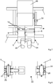
Figure 6 shows an enlargement of a second part inFigure 4 ; -
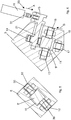
Figure 7 shows a view from above of the machine inFigure 1 ; -
Figure 8 shows a cross-section of a component of the machine inFigure 3b ; -
Figure 9 shows a side view of a second embodiment of the welding machine according to the invention. - The same numerals and letters of reference in the figures identify the same elements or components.
- Some examples of a welding machine of the flash welding type according to the invention are illustrated with reference to the Figures.
- In all of the embodiments of the invention, the welding machine, which is suitable for welding the tail of a first longitudinal metal product to the head of a second longitudinal metal product along a feeding direction of said longitudinal metal products, comprises a
carriage 1, adapted to slide along said feeding direction above a roller table (not shown) on which the longitudinal metal products, such as billets, blooms or bars, advance. - The
carriage 1 supports: - a first structure, or body, 2 connected, for example fixed, to said
carriage 1; - first clamping means 3, 4, provided on the
first structure 2, for clamping the tail of the first metal product, or the head of the second metal product; - a second structure, or body, 5 connected to the
first structure 2 so as to slide, parallel to the feeding direction, with respect both to thefirst structure 2 and thecarriage 1; - second clamping means 6, 7, provided on the
second structure 5, for clamping the head of the second metal product, or the tail of the first metal product; - first adjustment means 22, 23 for moving the
second structure 5 close to, or away from thefirst structure 2 along the feeding direction, i.e. to adjust the distance of thesecond structure 5 from thefirst structure 2 along said feeding direction. - The
first structure 2 is fixed to thecarriage 1 by means of at least oneconstraint 33, preferably only one constraint. Theconstraint 33 can allow a slight oscillation of thefirst structure 2 thereabout. Thus, thesecond structure 5, also being connected to thefirst structure 2, can oscillate slightly about theconstraint 33. - In a first embodiment of the welding machine, shown in
Figures 1-8 , thefirst structure 2 defines a longitudinal axis Z (Figure 1 ), which is inclined, with respect to the horizontal plane defined by thecarriage 1, by an acute angle, preferably between 30° and 50°, for example 45°. Thesecond structure 5, defining a longitudinal axis Z' thereof (Figure 2 ), is arranged substantially parallel to thefirst structure 2 and spaced apart from the latter along the feeding direction of the products to be welded. - In a second embodiment of the welding machine, shown in
Figure 9 , thefirst structure 2 defines a substantially horizontal longitudinal axis Z (not shown). Similarly, thesecond structure 5, defining a longitudinal axis Z' thereof (Figure 9 ), is arranged substantially parallel to thefirst structure 2 and spaced apart from the latter along the feeding direction of the products to be welded. - In all of the embodiments, the first clamping means 3, 4 of the
first structure 2 comprise respective upper clamps and lower clamps. While the lower clamps are fixed clamps, the upper clamps can be moved by a respective movement cylinder 34 (Figure 1 ). - The second clamping means 6, 7 of the
second structure 5 comprise respective upper clamps and lower clamps. In this case, too, while the lower clamps are fixed clamps, the upper clamps can be moved by a respective movement cylinder 35 (Figures 2 and9 ). - Alternatively, it is nonetheless also possible to make the lower clamps movable. The welding machine is provided with a
transformer 36 andconductors 37 connected to thestructure 2 and to thestructure 5, respectively, to supply current, in a known manner, to the products to be welded. - Advantageously, second adjustment means are provided, for adjusting the position of the
second structure 5 with respect to thefirst structure 2 by means of a lifting of thesecond structure 5 along a plane transversal, preferably orthogonal, to said feeding direction, so as to align the tail and the head of the two products along the feeding direction. This lifting can occur by means of a slight rotation of thesecond structure 5 about a rotation axis C parallel to the feeding direction (Figures 2 and9 ). In the first embodiment (Figure 2 ) said rotation axis C is preferably arranged on the side opposite to the side where thetransformer 36 is present (Figure 2 ). - In particular, the
second structure 5 is connected in a cantilever manner to thefirst structure 2, saidsecond structure 5 being sliding on at least twosupports first structure 2 and having longitudinal axes parallel to each other and to the feeding direction of the products. - Preferably, the second adjustment means are integrated into the
second structure 5 and comprise a pushingdevice 20 configured to push on at least one of the cantileveredbeams second structure 5 slightly with respect to thefirst structure 2. - In the embodiments shown in the Figures, only one first
cantilevered beam 8 and one secondcantilevered beam 9 are provided, fixed to a first end and to a second end of thefirst structure 2, respectively. - Optionally, the first end of the second structure 5 (which is the upper end in the case of the welding machine being inclined in
Figure 2 ) can be slidably connected to a first end of thefirst structure 2 by means of the firstcantilevered beam 8, or upper cantilevered beam. Whereas, the second end of the second structure 5 (which is the lower end in the case of the welding machine being inclined inFigure 2 ) can be slidably connected to a second end of thefirst structure 2 by means of the secondcantilevered beam 9, or lower cantilevered beam. - Therefore, the
second structure 5 is sliding on the upper and lowercantilevered beams first structure 2. - Preferably, the pushing
device 20 is configured to push on the lowercantilevered beam 9 to lift thesecond structure 5. - As shown in the variant in
Figures 3a and 3b , but which can be valid for both embodiments described herein, the uppercantilevered beam 8 has a first portion 8' thereof having a quadrangular section, which is distal from thefirst structure 2 and inserted into a through hole 10 (Figure 5 ), having a quadrangular section, of thesecond structure 5. Preferably, the uppercantilevered beam 8 has a second portion thereof that is proximal and fixed integrally to thefirst structure 2, while the first portion 8' is cantilevered and, optionally, there is provided a shoulder between said first portion 8' and the adjacent second portion. Optionally, also the second portion of the cantileveredbeam 8 has a quadrangular section, and, preferably, the side surfaces of said second portion are parallel to the corresponding side surfaces of the first portion 8'. - The through
hole 10 is provided, on at least two opposite side surfaces, with first rollers 12 (Figures 4 and5 ) for a sliding of thesecond structure 5 on the cantileveredbeam 8, in particular on the portion 8' thereof. - Preferably, a pair of
first rollers 12 is provided on each of said two opposite side surfaces of the throughhole 10. It is not excluded that only oneroller 12, or three ormore rollers 12, can be provided, on each of said two opposite side surfaces, inside the throughhole 10. - Advantageously, the
first rollers 12 have aconvex side surface 30, i.e. slightly convex, in contact with a respective side surface of the uppercantilevered beam 8 to facilitate a small rotation, about the axis C, of thesecond structure 5 along a plane, which is transversal, preferably orthogonal, to the feeding direction. - The
first rollers 12 are idle rollers, accommodated in respective seats obtained in thesecond structure 5, i.e. seats obtained in said two inner and opposite side surfaces of the throughhole 10.Such rollers 12 protrude slightly into said throughhole 10 to come into contact with mutually opposite surfaces of the uppercantilevered beam 8. - Similarly, the lower
cantilevered beam 9 has a first portion 9' thereof having a quadrangular section, distal from thefirst structure 2 and inserted into a through hole 11 (Figure 6 ), having a quadrangular section, of thesecond structure 5. Preferably, the lowercantilevered beam 9 has a second portion thereof which is proximal and fixed integrally to thefirst structure 2, while the first portion 9' is cantilevered and, optionally, there is provided a shoulder between said first portion 9' and the adjacent second portion. Optionally, also the second portion of the cantileveredbeam 9 has a quadrangular section, and preferably the side surfaces of said second portion are not parallel to the corresponding side surfaces of the first portion 9' (Figure 3a ). - Alternatively, the shape of the cross-section of the first portion 9' of the lower
cantilevered beam 9 can be different from quadrangular, for example round. - In a variant, the through
hole 11 is provided with foursecond rollers second roller hole 11, for a sliding of thesecond structure 5 on the cantileveredbeam 9. - In particular, each
second roller second structure 5, i.e. in a respective seat obtained in a corresponding inner side surface of the throughhole 11, and protruding into said throughhole 11 for possibly coming into contact with a respective side surface of the lowercantilevered beam 8. The twoside rollers lower roller 17 are idle rollers, while theupper roller 14 is a controlled roller, which however is idle on rotation. - Advantageously, the
upper roller 14 of said four second rollers is mounted on an eccentric portion of arotating shaft 21, and the pushingdevice 20 is adapted to rotate saidrotating shaft 21 so that theupper roller 14, protruding more from the seat thereof, pushes on the underlying lowercantilevered beam 9 in order to lift thesecond structure 5. - In fact, in a rest position, the first portion 9' of the lower
cantilevered beam 9 is in contact with theupper roller 14, which is in a partially retracted position inside the seat thereof, and in contact with twoside rollers gap 19 can be present between thelower roller 17 of said second rollers and the first portion 9' of the lowercantilevered beam 9. - Whereas, in a thrust position, the
upper roller 14 is in a more protruding position from the seat thereof, with respect to the rest position, so that thesecond structure 5 is lifted until possibly making contact between thelower roller 17 and the first portion 9'. - In an alternative variant, the
lower roller 17 is not provided and, in the thrust position, thesecond structure 5 is lifted without making contact between the lower inner side surface of the throughhole 11, i.e. the inner side surface not provided with a roller, and the first portion 9'. - In a preferred variant of the invention, shown in
Figure 6 , the pushingdevice 20 comprises anactuator 16, preferably a hydraulic cylinder, adapted to actuate, for example by means of astem 31 connected to the piston (not visible), alever 15 at a first end thereof, saidlever 15 being integral at a second end thereof with the rotatingshaft 21 onto whose eccentric portion theupper roller 14 is keyed. - Therefore, by actuating the
actuator 16, thestem 31 moves downwards along the arrow A lowering the first end of thelever 15 connected to thestem 31 and, thus, causing the second end of thelever 15, for example keyed to theshaft 21, to rotate around the same rotation axis as theshaft 21. In this way, theshaft 21 will rotate, also causing theupper roller 14 to rotate. Preferably, the maximum rotation of theshaft 21 about the axis thereof, and thus the maximum rotation of theupper roller 14, is by an angle of less than, or equal to 180°, for example between 45° to 135°. Following the rotation of theupper roller 14, the latter will be more protruding from the seat thereof, causing a lifting of the lower part of thesecond structure 5 along the arrow B (Figure 6 ) until possibly also bringing thelower roller 17 into contact with the portion 9' of the lowercantilevered beam 9. - Preferably, as visible in
Figure 2 and9 , the uppercantilevered beam 8 is configured so that the first portion 8' thereof has a plane of symmetry X, which is perpendicular to the mutually opposite two side surfaces thereof in contact with thefirst rollers 12; while the lowercantilevered beam 9 is configured so that the first portion 9' thereof has a plane of symmetry Y parallel to the side surface thereof in contact with theupper roller 14. The plane of symmetry X and the plane of symmetry Y are incident, defining an axis C, which is parallel to the feeding direction and about which thesecond structure 5 can rotate slightly. In the first embodiment, shown inFigure 2 , the acute angle α defined by the planes X and Y, in the rest position (i.e. when thesecond structure 5 is not lifted), can be between 40° and 90°, preferably between 45° and 65°. The rotation of thesecond structure 5 about the axis C can occur in a range between 1° and 5°, preferably between 1° and 3°. - This rotation is facilitated by the presence of the
convex side surface 30 of thefirst rollers 12 in contact with the respective side surface of the uppercantilevered beam 8. - In one variant, the plane of symmetry X forms an acute angle between 25° and 45° with a horizontal plane defined by the
carriage 1; while the plane of symmetry Y forms an acute angle between 15° and 20° with said horizontal plane. The sum of these two acute angles is equal to the acute angle α (Figure 2 ). - Furthermore, the axis C is arranged, with respect to the welding machine, on side opposite to where the
transformer 36 is present (Figure 2 ). - In the second embodiment, shown in
Figure 9 , the acute angle α' defined by the planes X and Y, in the rest position, can be between 5° and 85°, preferably between 30° and 60°. The rotation of thesecond structure 5 about the axis C can occur in a range between 1° and 5°, preferably between 1° and 3°. - This rotation is facilitated by the presence of the
convex side surface 30 of thefirst rollers 12 in contact with the respective side surface of the uppercantilevered beam 8. - In this embodiment, the plane of symmetry Y is substantially horizontal and, in the rest position, also parallel to the longitudinal axis Z' of the
second structure 5. Preferably, in both embodiments, the axis C is an axis external to the welding machine, i.e. an axis which does not intersect any component of the welding machine. - Optionally, the first adjustment means are upsetting
cylinders - The upsetting
cylinders first structure 2 and, at a second end thereof, to thesecond structure 5 by means ofrespective pins cylinder second structure 5 to be lifted with respect to thefirst structure 2 fixed to thecarriage 1, facilitating a slight inclination of the same upsetting cylinders with respect to the normally horizontal position thereof, which is parallel to the feeding direction of the products. - Preferably, in the variants shown in the Figures, a first upsetting
cylinder 22 is arranged at the bottom behind the welding machine, i.e. at the bottom behind both of thefirst structure 2 and of thesecond structure 5, on the side opposite to the side on which the uppercantilevered beam 8 is fixed and/or on which thetransformer 36 is provided. Instead, the second upsettingcylinder 23 is arranged at one end of the welding machine, for example, at the foot both of thefirst structure 2 and of thesecond structure 5 in the case of the variant inFigure 1 . Preferably, in all of the embodiments, the second upsettingcylinder 23 is arranged close to the side opposite to the side on which the first upsettingcylinder 22 is provided. - Preferably, the axes of the
pins cylinder 22 define a plane, which is transversal (Figures 1 and9 ), for example substantially orthogonal, to the plane defined by the axes of the pins of the upsettingcylinder 23. - In one advantageous variant of the invention, at least one
sensor 32 is provided, for example a camera, a probe, a laser sensor or another suitable sensor, which is adapted to detect the difference in height between the head of the metal product entering the welding machine and the tail of the preceding metal product. A suitable software acquires the value of said difference in height and sends a command to the second adjustment means, preferably the pushingdevice 20, to automatically adjust the position of thesecond structure 5 with respect to thefirst structure 2. - In the case of using a camera, it is possible to transmit the images to a monitor, allowing an operator, at a safe distance from the machine, to check and adjust the alignment of the metal products, and thus, the centering position of the welding joint. Described below are the steps of a flash welding method according to the present invention.
- The welding method, which can be performed by means of the machine described above, comprises the following steps:
- a) clamping the tail of the first metal product or the head of the second metal product by means of first clamping means 3, 4 provided on the
first structure 2, and clamping the head of the second metal product or the tail of the first metal product by means of second clamping means 6, 7 provided on thesecond structure 5; - b) adjusting, by means of the second adjustment means, the position of the
second structure 5 with respect to thefirst structure 2 by means of a lifting, preferably by means of a rotation, of thesecond structure 5 along a plane transversal to said feeding direction, so as to align the tail and the head along the feeding direction; - c) welding the tail and the head by moving the
second structure 5 close to thefirst structure 2 along said feeding direction, by means of the first adjustment means. - In step b) the rotation of the
second structure 5 occurs about the axis C, parallel to the feeding direction, in a range between 1° and 5°, preferably between 1° and 3°. Preferably, the following steps are comprised between step a) and step b): - detecting a difference in height, by means of at least one
sensor 32, between the head of the metal product entering the welding machine and the tail of the preceding metal product; - acquiring the value of said difference in height by means of a software and sending a command to the second adjustment means, to adjust the position of the
second structure 5 with respect to thefirst structure 2.
and wherein second adjustment means are provided for adjusting, along a plane transversal to said feeding direction, the position of the second structure with respect to the first structure by means of a lifting of the second structure, in order to align said head and said tail.
Claims (16)
- A welding machine of the flash welding type for welding a tail of a first longitudinal metal product to a head of a second longitudinal metal product along a feeding direction of said longitudinal metal products, the machine comprising a carriage (1) adapted to slide along the feeding direction, said carriage (1) supporting- a first structure (2) fixed to said carriage (1);- first clamping means (3, 4), provided on said first structure (2), for clamping the tail of the first metal product or the head of the second metal product;- a second structure (5) connected to said first structure (2) so as to slide, parallel to the feeding direction, with respect both to the first structure (2) and the carriage (1);- second clamping means (6, 7), provided on said second structure (5), for clamping the head of the second metal product or the tail of the first metal product;wherein first adjustment means are provided for moving the second structure (5) close to, or away from the first structure (2) along said feeding direction;
and wherein second adjustment means are provided for adjusting, along a plane transversal to said feeding direction, the position of the second structure (5) with respect to the first structure (2) by means of a lifting of the second structure (5), in order to align said tail and said head. - A machine according to claim 1, wherein said first adjustment means are upsetting cylinders (22, 23), preferably only two in number; wherein said upsetting cylinders (22, 23) are hinged at a first end thereof to the first structure (2) and at a second end thereof to the second structure (5) by means of respective pins (24, 25); and wherein both the first end and the second end of each upsetting cylinder (22, 23) are provided with a respective ball joint.
- A machine according to claim 1 or 2, wherein the second structure (5) is connected to the first structure (2) in a cantilever manner, said second structure (5) being slidable on at least two supports (8, 9) fixed to, and at least partially protruding from, the first structure (2) and having longitudinal axes parallel to each other and to the feeding direction; wherein at least one first portion (8') of a first support (8) of said at least two supports (8, 9) is cantilevered and has at least one plane of symmetry X; wherein at least one first portion (9') of a second support (9) of said at least two supports (8, 9) is cantilevered and has at least one plane of symmetry Y; and wherein the plane of symmetry X and the plane of symmetry Y are incident, thus defining an axis C, parallel to the feeding direction and about which the second structure (5) can rotate.
- A machine according to claim 3, wherein said second adjustment means are integrated into the second structure (5) and comprise a pushing device (20) configured to push on at least one of the two supports (8, 9) to lift the second structure (5).
- A machine according to claim 4, wherein said at least two supports are a first cantilevered beam (8) and a second cantilevered beam (9), preferably fixed to a first end and a second end of the first structure (2), respectively; preferably wherein said pushing device (20) is configured to push on said second cantilevered beam (9) to lift the second structure (5).
- A machine according to claim 4 or 5, wherein the first cantilevered beam (8) has the first portion (8') thereof, having a quadrangular section, which is distal from the first structure (2) and inserted into a first through hole (10), having a quadrangular section, of the second structure (5) provided, on at least two opposite inner sides, with first rollers (12) for the second structure (5) to slide on said first cantilevered beam (8), and wherein the plane of symmetry X of the first portion (8') is perpendicular to the side surfaces of the first portion (8') in contact with the first rollers (12); preferably wherein the second cantilevered beam (9) has the first portion (9') thereof, having a quadrangular section, which is distal from the first structure (2) and inserted into a second through hole (11), having a quadrangular section, of the second structure (5) provided with at least three second rollers (13, 14, 17, 18), each second roller being arranged at a respective inner side of the second through hole, for the second structure (5) to slide on said second cantilevered beam (9), and wherein the plane of symmetry Y of the first portion (9') is parallel to the side surface of the first portion (9') in contact with an upper roller (14) of said at least three second rollers; preferably wherein the upper roller (14) of said at least three second rollers is mounted on an eccentric portion of a rotating shaft (21) and the pushing device (20) is adapted to rotate said rotating shaft so that said upper roller (14) pushes on said second cantilevered beam (9) to lift the second structure (5).
- A machine according to claim 6, wherein, in a rest position, the first portion (9') of the second cantilevered beam (9) is in contact with the upper roller (14), which is in a retracted position inside a seat thereof, and in contact with two side rollers (13, 18) of said second rollers, while a gap (19) is present between a lower inner side of the second through hole (11) and said first portion (9') or between a lower roller (17) of said second rollers and said first portion (9'); and wherein, in a pushing position, the upper roller (14) is in a more protruding position from the seat thereof, with respect to the case of the rest position, so that the second structure (5) is lifted up, preferably lifted up to a possible contact between the lower roller (17) and the first portion (9').
- A machine according to claim 6 or 7, wherein the first cantilevered beam (8) has a second portion thereof that is proximal and integrally fixed to the first structure (2), while the first portion (8') is cantilevered; and/or wherein the second cantilevered beam (9) has a second portion thereof that is proximal and integrally fixed to the first structure (2), while the first portion (9') is cantilevered.
- A machine according to one of the claims from 6 to 8, wherein said pushing device (20) comprises an actuator (16) adapted to actuate a lever (15) at a first end thereof, said lever (15) being integral, at a second end thereof, with the rotating shaft (21) onto which the upper roller (14) is keyed.
- A machine according to one of the claims from 6 to 9, wherein a pair of first rollers (12) is provided on each of said two opposite inner sides of the first through hole (10).
- A machine according to one of the claims from 6 to 10, wherein said first rollers (12) have a convex side surface (30) in contact with a respective side surface of the first cantilevered beam (8).
- A machine according to one of the claims from 6 to 11, wherein said first rollers (12) are idle, accommodated in respective seats obtained in the second structure (5) and protruding into the first through hole (10) to come into contact with mutually opposite surfaces of the first cantilevered beam (8); preferably, wherein the two side rollers (13, 18) and the possible lower roller (17) of said second rollers are idle, accommodated in respective seats obtained in the second structure (5) and protruding into the second through hole (11), while the upper roller (14) is a driven roller, but idle to the rotation.
- A machine according to any one of the preceding claims, wherein there is provided at least one sensor (32), adapted to detect the difference in height between the head of the metal product entering the welding machine and the tail of a further metal product preceding said metal product; and wherein there is provided a software, adapted to acquire the value of said difference in height and send a command to the second adjustment means to adjust the position of the second structure (5) with respect to the first structure (2).
- A welding method of the flash welding type for welding together a tail of a first longitudinal metal product to a head of a second longitudinal metal product fed along a feeding direction of said longitudinal metal products, the method being performable by means of a machine according to any one of the preceding claims and comprising the following stages:a) clamping the tail of the first metal product or the head of the second metal product by means of first clamping means (3, 4) provided on said first structure (2), and clamping the head of the second metal product or the tail of the first metal product by means of second clamping means (6, 7) provided on said second structure (5);b) adjusting, by means of said second adjustment means, the position of the second structure (5) with respect to the first structure (2) by means of a lifting of the second structure (5) along a plane transversal to said feeding direction, so as to align said tail and said head along the feeding direction;c) welding said tail and said head by moving the second structure (5) close to the first structure (2) along said feeding direction, by means of said first adjustment means.
- A method according to claim 14, wherein said lifting occurs by means of a rotation of the second structure (5) about an axis C, parallel to the feeding direction, in a range between 1° and 5°, preferably between 1° and 3°.
- A method according to claim 14 or 15, wherein the following stages are provided between stage a) and stage b):- detecting a difference in height, by means of at least one sensor (32), between the head of the metal product entering the welding machine and the tail of a further metal product preceding said metal product;- acquiring the value of said difference in height and sending, by means of a software, a command to the second adjustment means to adjust the position of the second structure (5) with respect to the first structure (2).
Applications Claiming Priority (1)
| Application Number | Priority Date | Filing Date | Title |
|---|---|---|---|
| IT102019000019750A IT201900019750A1 (en) | 2019-10-24 | 2019-10-24 | WELDING MACHINE AND RELATIVE METHOD |
Publications (2)
| Publication Number | Publication Date |
|---|---|
| EP3812055A1 true EP3812055A1 (en) | 2021-04-28 |
| EP3812055B1 EP3812055B1 (en) | 2023-06-07 |
Family
ID=69811530
Family Applications (1)
| Application Number | Title | Priority Date | Filing Date |
|---|---|---|---|
| EP20203200.9A Active EP3812055B1 (en) | 2019-10-24 | 2020-10-22 | A welding machine and related method |
Country Status (6)
| Country | Link |
|---|---|
| US (1) | US20210121972A1 (en) |
| EP (1) | EP3812055B1 (en) |
| JP (1) | JP7075978B2 (en) |
| CN (1) | CN112705888A (en) |
| IT (1) | IT201900019750A1 (en) |
| RU (1) | RU2760188C1 (en) |
Cited By (2)
| Publication number | Priority date | Publication date | Assignee | Title |
|---|---|---|---|---|
| IT202200013807A1 (en) * | 2022-06-30 | 2023-12-30 | Danieli Off Mecc | WELDING MACHINE |
| EP4559613A1 (en) * | 2023-11-22 | 2025-05-28 | SMS group S.p.A. | Welding machine for longitudinal metal objects, in particular billets |
Families Citing this family (6)
| Publication number | Priority date | Publication date | Assignee | Title |
|---|---|---|---|---|
| US12397366B2 (en) * | 2020-02-03 | 2025-08-26 | Danieli & C. Officine Meccaniche S.P.A. | Welding machine |
| CN113770620A (en) * | 2021-08-09 | 2021-12-10 | 福建占峰通风设备有限公司 | A positioning device for welding and processing fire valve blades |
| CN114769869A (en) * | 2022-06-13 | 2022-07-22 | 东莞市永勤精密技术有限公司 | Laser welding machine for machining mobile phone parts |
| GB202213171D0 (en) | 2022-09-08 | 2022-10-26 | Pong David Teng | Flash welding for billets with "down cut" billet ends |
| CN118002901B (en) * | 2024-04-08 | 2024-06-07 | 吉林大学 | Suspension type spot welding device convenient for welding various vehicle types |
| CN120551671B (en) * | 2025-07-16 | 2025-11-28 | 济宁鑫方晟钢结构工程有限公司 | Steel construction processing welding set |
Citations (4)
| Publication number | Priority date | Publication date | Assignee | Title |
|---|---|---|---|---|
| EP0956911A2 (en) * | 1993-06-15 | 1999-11-17 | Kawasaki Steel Corporation | A continuous hot rolling method and an apparatus for carrying out said method |
| US20010017290A1 (en) * | 2000-02-24 | 2001-08-30 | Lara Alejandro Sanz | Method and device for welding |
| EP1731233A1 (en) * | 2005-06-09 | 2006-12-13 | JP Steel Plantech Co. | Continuous rolling method and continuous rolling apparatus |
| WO2009003950A1 (en) * | 2007-06-29 | 2009-01-08 | Danieli & C. Officine Meccaniche S.P.A. | A welding device and related process |
Family Cites Families (14)
| Publication number | Priority date | Publication date | Assignee | Title |
|---|---|---|---|---|
| US4414454A (en) * | 1981-08-13 | 1983-11-08 | H. A. Schlatter Ag | Method of welding continuous rails and apparatus therefor |
| SU1146163A1 (en) * | 1984-02-06 | 1985-03-23 | Всесоюзный ордена Ленина научно-исследовательский и проектно-конструкторский институт металлургического машиностроения | Machine for butt resistance welding of strips by flashing |
| US4785154A (en) * | 1987-05-20 | 1988-11-15 | Cranston Machinery Co., Inc. | Method and apparatus for joining together the ends of a metallic band by resistance inert gas welding |
| JPH0557454A (en) * | 1991-08-27 | 1993-03-09 | Kobe Steel Ltd | Device for determining quality of upsetting operation for flash welding machine |
| RU2030265C1 (en) * | 1992-04-20 | 1995-03-10 | Производственное Объединение "Электростальтяжмаш" | Flats butt welder |
| ATE145574T1 (en) * | 1992-11-09 | 1996-12-15 | Schlatter Ag | FLASH BUT WELDING SYSTEM |
| SE9504368D0 (en) * | 1995-12-05 | 1995-12-05 | Esab Ab | Hopsvetsningsanordning |
| IT1288863B1 (en) * | 1996-03-15 | 1998-09-25 | Danieli Off Mecc | CONTINUOUS LAMINATION PROCESS FOR SHEETS AND / OR TAPES AND RELATED CONTINUOUS ROLLING LINE |
| JP2007289995A (en) | 2006-04-25 | 2007-11-08 | Jfe Koken Corp | Welding equipment |
| EP1960132B1 (en) * | 2006-04-27 | 2009-07-15 | SMS Siemag AG | Apparatus and method for the connection of strips |
| AU2009344628B2 (en) * | 2009-04-16 | 2014-06-12 | Davide Vaia | Welding head for rail welding |
| CN102049602B (en) * | 2010-12-03 | 2013-03-27 | 中国铁道科学研究院金属及化学研究所 | Steel rail flash welding machine and container type steel rail flash welding equipment |
| EP2821176A1 (en) * | 2013-07-02 | 2015-01-07 | Siemens VAI Metals Technologies GmbH | Device for moving an arrangement for cutting and welding metal strips ; Methof of cutting and welding using such device |
| JP5847216B2 (en) | 2014-02-18 | 2016-01-20 | 日本発條株式会社 | Method for manufacturing link arm member |
-
2019
- 2019-10-24 IT IT102019000019750A patent/IT201900019750A1/en unknown
-
2020
- 2020-10-19 JP JP2020175117A patent/JP7075978B2/en active Active
- 2020-10-22 US US17/077,420 patent/US20210121972A1/en not_active Abandoned
- 2020-10-22 EP EP20203200.9A patent/EP3812055B1/en active Active
- 2020-10-22 RU RU2020134715A patent/RU2760188C1/en active
- 2020-10-23 CN CN202011144280.5A patent/CN112705888A/en active Pending
Patent Citations (4)
| Publication number | Priority date | Publication date | Assignee | Title |
|---|---|---|---|---|
| EP0956911A2 (en) * | 1993-06-15 | 1999-11-17 | Kawasaki Steel Corporation | A continuous hot rolling method and an apparatus for carrying out said method |
| US20010017290A1 (en) * | 2000-02-24 | 2001-08-30 | Lara Alejandro Sanz | Method and device for welding |
| EP1731233A1 (en) * | 2005-06-09 | 2006-12-13 | JP Steel Plantech Co. | Continuous rolling method and continuous rolling apparatus |
| WO2009003950A1 (en) * | 2007-06-29 | 2009-01-08 | Danieli & C. Officine Meccaniche S.P.A. | A welding device and related process |
Cited By (3)
| Publication number | Priority date | Publication date | Assignee | Title |
|---|---|---|---|---|
| IT202200013807A1 (en) * | 2022-06-30 | 2023-12-30 | Danieli Off Mecc | WELDING MACHINE |
| WO2024003802A1 (en) * | 2022-06-30 | 2024-01-04 | Danieli & C. Officine Meccaniche S.P.A. | Welding machine |
| EP4559613A1 (en) * | 2023-11-22 | 2025-05-28 | SMS group S.p.A. | Welding machine for longitudinal metal objects, in particular billets |
Also Published As
| Publication number | Publication date |
|---|---|
| RU2760188C1 (en) | 2021-11-22 |
| EP3812055B1 (en) | 2023-06-07 |
| JP2021065935A (en) | 2021-04-30 |
| CN112705888A (en) | 2021-04-27 |
| IT201900019750A1 (en) | 2021-04-24 |
| JP7075978B2 (en) | 2022-05-26 |
| US20210121972A1 (en) | 2021-04-29 |
Similar Documents
| Publication | Publication Date | Title |
|---|---|---|
| EP3812055B1 (en) | A welding machine and related method | |
| CN109623208B (en) | Automatic welding system for robot | |
| CN112756757B (en) | Resistance welding method for automatically welding inner end of steel coil | |
| KR102047623B1 (en) | Spindle and coupling assembly equipment of rolling mill | |
| CA2220801C (en) | Rolled plated joining apparatus and continuous hot rolling apparatus equipped with the same | |
| US3982091A (en) | Welding apparatus | |
| EP4100179B1 (en) | Welding machine | |
| CN115502630B (en) | Workpiece group welding workstation and control method thereof | |
| US6504128B2 (en) | Apparatus for joining together two metallic bands | |
| CN111660029A (en) | Automatic welding equipment for off-track type girder | |
| CN115724173A (en) | Tilter, control method thereof and excavator assembly line | |
| RU2805324C1 (en) | Welding unit | |
| CN215543992U (en) | Rotary bending device for elbow pipe on railing of tower crane | |
| EP4547414B1 (en) | Welding machine | |
| CN218134048U (en) | Quick replacement device for main roll of ring rolling mill | |
| CN121892789A (en) | A welding workstation and welding method | |
| KR100854853B1 (en) | Blade changer of cutter | |
| SU856722A1 (en) | Production line for producing elongated metal structures from shapes | |
| CN118904898A (en) | Liftable type vertical roller mill for large-specification flat steel | |
| JP4478070B2 (en) | Slab cutting device in continuous casting machine | |
| SU1227393A1 (en) | Automatic welding device | |
| CA2541938C (en) | Rolled plate joining apparatus and continuous hot rolling apparatus equipped with the same | |
| GB2096935A (en) | Methods of, and apparatus for, dividing metal slabs or ingots into sections | |
| CN120095265A (en) | Automatic foot welding device | |
| JPS5874262A (en) | Casting device |
Legal Events
| Date | Code | Title | Description |
|---|---|---|---|
| PUAI | Public reference made under article 153(3) epc to a published international application that has entered the european phase |
Free format text: ORIGINAL CODE: 0009012 |
|
| STAA | Information on the status of an ep patent application or granted ep patent |
Free format text: STATUS: THE APPLICATION HAS BEEN PUBLISHED |
|
| AK | Designated contracting states |
Kind code of ref document: A1 Designated state(s): AL AT BE BG CH CY CZ DE DK EE ES FI FR GB GR HR HU IE IS IT LI LT LU LV MC MK MT NL NO PL PT RO RS SE SI SK SM TR |
|
| AX | Request for extension of the european patent |
Extension state: BA ME |
|
| RIN1 | Information on inventor provided before grant (corrected) |
Inventor name: TOMAT, CLAUDIO Inventor name: TRINCO, ANDREA |
|
| STAA | Information on the status of an ep patent application or granted ep patent |
Free format text: STATUS: REQUEST FOR EXAMINATION WAS MADE |
|
| 17P | Request for examination filed |
Effective date: 20211028 |
|
| RBV | Designated contracting states (corrected) |
Designated state(s): AL AT BE BG CH CY CZ DE DK EE ES FI FR GB GR HR HU IE IS IT LI LT LU LV MC MK MT NL NO PL PT RO RS SE SI SK SM TR |
|
| GRAP | Despatch of communication of intention to grant a patent |
Free format text: ORIGINAL CODE: EPIDOSNIGR1 |
|
| STAA | Information on the status of an ep patent application or granted ep patent |
Free format text: STATUS: GRANT OF PATENT IS INTENDED |
|
| INTG | Intention to grant announced |
Effective date: 20220831 |
|
| GRAS | Grant fee paid |
Free format text: ORIGINAL CODE: EPIDOSNIGR3 |
|
| GRAA | (expected) grant |
Free format text: ORIGINAL CODE: 0009210 |
|
| STAA | Information on the status of an ep patent application or granted ep patent |
Free format text: STATUS: THE PATENT HAS BEEN GRANTED |
|
| AK | Designated contracting states |
Kind code of ref document: B1 Designated state(s): AL AT BE BG CH CY CZ DE DK EE ES FI FR GB GR HR HU IE IS IT LI LT LU LV MC MK MT NL NO PL PT RO RS SE SI SK SM TR |
|
| REG | Reference to a national code |
Ref country code: GB Ref legal event code: FG4D |
|
| P01 | Opt-out of the competence of the unified patent court (upc) registered |
Effective date: 20230511 |
|
| REG | Reference to a national code |
Ref country code: CH Ref legal event code: EP Ref country code: AT Ref legal event code: REF Ref document number: 1573432 Country of ref document: AT Kind code of ref document: T Effective date: 20230615 Ref country code: DE Ref legal event code: R096 Ref document number: 602020011742 Country of ref document: DE |
|
| REG | Reference to a national code |
Ref country code: LT Ref legal event code: MG9D |
|
| REG | Reference to a national code |
Ref country code: NL Ref legal event code: MP Effective date: 20230607 |
|
| PG25 | Lapsed in a contracting state [announced via postgrant information from national office to epo] |
Ref country code: SE Free format text: LAPSE BECAUSE OF FAILURE TO SUBMIT A TRANSLATION OF THE DESCRIPTION OR TO PAY THE FEE WITHIN THE PRESCRIBED TIME-LIMIT Effective date: 20230607 Ref country code: NO Free format text: LAPSE BECAUSE OF FAILURE TO SUBMIT A TRANSLATION OF THE DESCRIPTION OR TO PAY THE FEE WITHIN THE PRESCRIBED TIME-LIMIT Effective date: 20230907 Ref country code: ES Free format text: LAPSE BECAUSE OF FAILURE TO SUBMIT A TRANSLATION OF THE DESCRIPTION OR TO PAY THE FEE WITHIN THE PRESCRIBED TIME-LIMIT Effective date: 20230607 |
|
| PG25 | Lapsed in a contracting state [announced via postgrant information from national office to epo] |
Ref country code: RS Free format text: LAPSE BECAUSE OF FAILURE TO SUBMIT A TRANSLATION OF THE DESCRIPTION OR TO PAY THE FEE WITHIN THE PRESCRIBED TIME-LIMIT Effective date: 20230607 Ref country code: NL Free format text: LAPSE BECAUSE OF FAILURE TO SUBMIT A TRANSLATION OF THE DESCRIPTION OR TO PAY THE FEE WITHIN THE PRESCRIBED TIME-LIMIT Effective date: 20230607 Ref country code: LV Free format text: LAPSE BECAUSE OF FAILURE TO SUBMIT A TRANSLATION OF THE DESCRIPTION OR TO PAY THE FEE WITHIN THE PRESCRIBED TIME-LIMIT Effective date: 20230607 Ref country code: LT Free format text: LAPSE BECAUSE OF FAILURE TO SUBMIT A TRANSLATION OF THE DESCRIPTION OR TO PAY THE FEE WITHIN THE PRESCRIBED TIME-LIMIT Effective date: 20230607 Ref country code: HR Free format text: LAPSE BECAUSE OF FAILURE TO SUBMIT A TRANSLATION OF THE DESCRIPTION OR TO PAY THE FEE WITHIN THE PRESCRIBED TIME-LIMIT Effective date: 20230607 |
|
| PG25 | Lapsed in a contracting state [announced via postgrant information from national office to epo] |
Ref country code: FI Free format text: LAPSE BECAUSE OF FAILURE TO SUBMIT A TRANSLATION OF THE DESCRIPTION OR TO PAY THE FEE WITHIN THE PRESCRIBED TIME-LIMIT Effective date: 20230607 |
|
| PG25 | Lapsed in a contracting state [announced via postgrant information from national office to epo] |
Ref country code: SK Free format text: LAPSE BECAUSE OF FAILURE TO SUBMIT A TRANSLATION OF THE DESCRIPTION OR TO PAY THE FEE WITHIN THE PRESCRIBED TIME-LIMIT Effective date: 20230607 |
|
| PG25 | Lapsed in a contracting state [announced via postgrant information from national office to epo] |
Ref country code: IS Free format text: LAPSE BECAUSE OF FAILURE TO SUBMIT A TRANSLATION OF THE DESCRIPTION OR TO PAY THE FEE WITHIN THE PRESCRIBED TIME-LIMIT Effective date: 20231007 |
|
| PG25 | Lapsed in a contracting state [announced via postgrant information from national office to epo] |
Ref country code: SM Free format text: LAPSE BECAUSE OF FAILURE TO SUBMIT A TRANSLATION OF THE DESCRIPTION OR TO PAY THE FEE WITHIN THE PRESCRIBED TIME-LIMIT Effective date: 20230607 Ref country code: SK Free format text: LAPSE BECAUSE OF FAILURE TO SUBMIT A TRANSLATION OF THE DESCRIPTION OR TO PAY THE FEE WITHIN THE PRESCRIBED TIME-LIMIT Effective date: 20230607 Ref country code: RO Free format text: LAPSE BECAUSE OF FAILURE TO SUBMIT A TRANSLATION OF THE DESCRIPTION OR TO PAY THE FEE WITHIN THE PRESCRIBED TIME-LIMIT Effective date: 20230607 Ref country code: PT Free format text: LAPSE BECAUSE OF FAILURE TO SUBMIT A TRANSLATION OF THE DESCRIPTION OR TO PAY THE FEE WITHIN THE PRESCRIBED TIME-LIMIT Effective date: 20231009 Ref country code: IS Free format text: LAPSE BECAUSE OF FAILURE TO SUBMIT A TRANSLATION OF THE DESCRIPTION OR TO PAY THE FEE WITHIN THE PRESCRIBED TIME-LIMIT Effective date: 20231007 Ref country code: EE Free format text: LAPSE BECAUSE OF FAILURE TO SUBMIT A TRANSLATION OF THE DESCRIPTION OR TO PAY THE FEE WITHIN THE PRESCRIBED TIME-LIMIT Effective date: 20230607 Ref country code: CZ Free format text: LAPSE BECAUSE OF FAILURE TO SUBMIT A TRANSLATION OF THE DESCRIPTION OR TO PAY THE FEE WITHIN THE PRESCRIBED TIME-LIMIT Effective date: 20230607 |
|
| PG25 | Lapsed in a contracting state [announced via postgrant information from national office to epo] |
Ref country code: PL Free format text: LAPSE BECAUSE OF FAILURE TO SUBMIT A TRANSLATION OF THE DESCRIPTION OR TO PAY THE FEE WITHIN THE PRESCRIBED TIME-LIMIT Effective date: 20230607 |
|
| REG | Reference to a national code |
Ref country code: DE Ref legal event code: R097 Ref document number: 602020011742 Country of ref document: DE |
|
| PLBE | No opposition filed within time limit |
Free format text: ORIGINAL CODE: 0009261 |
|
| STAA | Information on the status of an ep patent application or granted ep patent |
Free format text: STATUS: NO OPPOSITION FILED WITHIN TIME LIMIT |
|
| PG25 | Lapsed in a contracting state [announced via postgrant information from national office to epo] |
Ref country code: DK Free format text: LAPSE BECAUSE OF FAILURE TO SUBMIT A TRANSLATION OF THE DESCRIPTION OR TO PAY THE FEE WITHIN THE PRESCRIBED TIME-LIMIT Effective date: 20230607 |
|
| PG25 | Lapsed in a contracting state [announced via postgrant information from national office to epo] |
Ref country code: SI Free format text: LAPSE BECAUSE OF FAILURE TO SUBMIT A TRANSLATION OF THE DESCRIPTION OR TO PAY THE FEE WITHIN THE PRESCRIBED TIME-LIMIT Effective date: 20230607 |
|
| 26N | No opposition filed |
Effective date: 20240308 |
|
| PG25 | Lapsed in a contracting state [announced via postgrant information from national office to epo] |
Ref country code: SI Free format text: LAPSE BECAUSE OF FAILURE TO SUBMIT A TRANSLATION OF THE DESCRIPTION OR TO PAY THE FEE WITHIN THE PRESCRIBED TIME-LIMIT Effective date: 20230607 Ref country code: IT Free format text: LAPSE BECAUSE OF FAILURE TO SUBMIT A TRANSLATION OF THE DESCRIPTION OR TO PAY THE FEE WITHIN THE PRESCRIBED TIME-LIMIT Effective date: 20230607 Ref country code: MC Free format text: LAPSE BECAUSE OF FAILURE TO SUBMIT A TRANSLATION OF THE DESCRIPTION OR TO PAY THE FEE WITHIN THE PRESCRIBED TIME-LIMIT Effective date: 20230607 |
|
| REG | Reference to a national code |
Ref country code: CH Ref legal event code: PL |
|
| REG | Reference to a national code |
Ref country code: BE Ref legal event code: MM Effective date: 20231031 |
|
| PG25 | Lapsed in a contracting state [announced via postgrant information from national office to epo] |
Ref country code: LU Free format text: LAPSE BECAUSE OF NON-PAYMENT OF DUE FEES Effective date: 20231022 |
|
| PG25 | Lapsed in a contracting state [announced via postgrant information from national office to epo] |
Ref country code: LU Free format text: LAPSE BECAUSE OF NON-PAYMENT OF DUE FEES Effective date: 20231022 |
|
| PG25 | Lapsed in a contracting state [announced via postgrant information from national office to epo] |
Ref country code: CH Free format text: LAPSE BECAUSE OF NON-PAYMENT OF DUE FEES Effective date: 20231031 |
|
| PG25 | Lapsed in a contracting state [announced via postgrant information from national office to epo] |
Ref country code: FR Free format text: LAPSE BECAUSE OF NON-PAYMENT OF DUE FEES Effective date: 20231031 Ref country code: CH Free format text: LAPSE BECAUSE OF NON-PAYMENT OF DUE FEES Effective date: 20231031 |
|
| PG25 | Lapsed in a contracting state [announced via postgrant information from national office to epo] |
Ref country code: BE Free format text: LAPSE BECAUSE OF NON-PAYMENT OF DUE FEES Effective date: 20231031 |
|
| PG25 | Lapsed in a contracting state [announced via postgrant information from national office to epo] |
Ref country code: IE Free format text: LAPSE BECAUSE OF NON-PAYMENT OF DUE FEES Effective date: 20231022 |
|
| PG25 | Lapsed in a contracting state [announced via postgrant information from national office to epo] |
Ref country code: IE Free format text: LAPSE BECAUSE OF NON-PAYMENT OF DUE FEES Effective date: 20231022 |
|
| PG25 | Lapsed in a contracting state [announced via postgrant information from national office to epo] |
Ref country code: BG Free format text: LAPSE BECAUSE OF FAILURE TO SUBMIT A TRANSLATION OF THE DESCRIPTION OR TO PAY THE FEE WITHIN THE PRESCRIBED TIME-LIMIT Effective date: 20230607 |
|
| REG | Reference to a national code |
Ref country code: AT Ref legal event code: UEP Ref document number: 1573432 Country of ref document: AT Kind code of ref document: T Effective date: 20230607 |
|
| PG25 | Lapsed in a contracting state [announced via postgrant information from national office to epo] |
Ref country code: BG Free format text: LAPSE BECAUSE OF FAILURE TO SUBMIT A TRANSLATION OF THE DESCRIPTION OR TO PAY THE FEE WITHIN THE PRESCRIBED TIME-LIMIT Effective date: 20230607 |
|
| GBPC | Gb: european patent ceased through non-payment of renewal fee |
Effective date: 20241022 |
|
| PG25 | Lapsed in a contracting state [announced via postgrant information from national office to epo] |
Ref country code: GB Free format text: LAPSE BECAUSE OF NON-PAYMENT OF DUE FEES Effective date: 20241022 |
|
| PG25 | Lapsed in a contracting state [announced via postgrant information from national office to epo] |
Ref country code: CY Free format text: LAPSE BECAUSE OF FAILURE TO SUBMIT A TRANSLATION OF THE DESCRIPTION OR TO PAY THE FEE WITHIN THE PRESCRIBED TIME-LIMIT; INVALID AB INITIO Effective date: 20201022 |
|
| PG25 | Lapsed in a contracting state [announced via postgrant information from national office to epo] |
Ref country code: HU Free format text: LAPSE BECAUSE OF FAILURE TO SUBMIT A TRANSLATION OF THE DESCRIPTION OR TO PAY THE FEE WITHIN THE PRESCRIBED TIME-LIMIT; INVALID AB INITIO Effective date: 20201022 |
|
| PG25 | Lapsed in a contracting state [announced via postgrant information from national office to epo] |
Ref country code: GR Free format text: LAPSE BECAUSE OF FAILURE TO SUBMIT A TRANSLATION OF THE DESCRIPTION OR TO PAY THE FEE WITHIN THE PRESCRIBED TIME-LIMIT; INVALID AB INITIO Effective date: 20201022 |
|
| PG25 | Lapsed in a contracting state [announced via postgrant information from national office to epo] |
Ref country code: TR Free format text: LAPSE BECAUSE OF FAILURE TO SUBMIT A TRANSLATION OF THE DESCRIPTION OR TO PAY THE FEE WITHIN THE PRESCRIBED TIME-LIMIT Effective date: 20230607 |
|
| PGFP | Annual fee paid to national office [announced via postgrant information from national office to epo] |
Ref country code: DE Payment date: 20251029 Year of fee payment: 6 |
|
| PGFP | Annual fee paid to national office [announced via postgrant information from national office to epo] |
Ref country code: AT Payment date: 20251029 Year of fee payment: 6 |