EP3811755A1 - Grass trimmer head and grass trimmer comprising the grass trimmer head - Google Patents
Grass trimmer head and grass trimmer comprising the grass trimmer head Download PDFInfo
- Publication number
- EP3811755A1 EP3811755A1 EP19845993.5A EP19845993A EP3811755A1 EP 3811755 A1 EP3811755 A1 EP 3811755A1 EP 19845993 A EP19845993 A EP 19845993A EP 3811755 A1 EP3811755 A1 EP 3811755A1
- Authority
- EP
- European Patent Office
- Prior art keywords
- spool
- elastic member
- head housing
- clutch mechanism
- state
- Prior art date
- Legal status (The legal status is an assumption and is not a legal conclusion. Google has not performed a legal analysis and makes no representation as to the accuracy of the status listed.)
- Withdrawn
Links
Images




Classifications
-
- A—HUMAN NECESSITIES
- A01—AGRICULTURE; FORESTRY; ANIMAL HUSBANDRY; HUNTING; TRAPPING; FISHING
- A01D—HARVESTING; MOWING
- A01D34/00—Mowers; Mowing apparatus of harvesters
- A01D34/01—Mowers; Mowing apparatus of harvesters characterised by features relating to the type of cutting apparatus
- A01D34/412—Mowers; Mowing apparatus of harvesters characterised by features relating to the type of cutting apparatus having rotating cutters
- A01D34/416—Flexible line cutters
- A01D34/4161—Means for feeding cutter line
-
- A—HUMAN NECESSITIES
- A01—AGRICULTURE; FORESTRY; ANIMAL HUSBANDRY; HUNTING; TRAPPING; FISHING
- A01D—HARVESTING; MOWING
- A01D34/00—Mowers; Mowing apparatus of harvesters
- A01D34/01—Mowers; Mowing apparatus of harvesters characterised by features relating to the type of cutting apparatus
- A01D34/412—Mowers; Mowing apparatus of harvesters characterised by features relating to the type of cutting apparatus having rotating cutters
- A01D34/416—Flexible line cutters
- A01D34/4166—Mounting or replacement of the lines
-
- A—HUMAN NECESSITIES
- A01—AGRICULTURE; FORESTRY; ANIMAL HUSBANDRY; HUNTING; TRAPPING; FISHING
- A01D—HARVESTING; MOWING
- A01D34/00—Mowers; Mowing apparatus of harvesters
- A01D34/01—Mowers; Mowing apparatus of harvesters characterised by features relating to the type of cutting apparatus
- A01D34/412—Mowers; Mowing apparatus of harvesters characterised by features relating to the type of cutting apparatus having rotating cutters
- A01D34/416—Flexible line cutters
-
- A—HUMAN NECESSITIES
- A01—AGRICULTURE; FORESTRY; ANIMAL HUSBANDRY; HUNTING; TRAPPING; FISHING
- A01D—HARVESTING; MOWING
- A01D34/00—Mowers; Mowing apparatus of harvesters
- A01D34/01—Mowers; Mowing apparatus of harvesters characterised by features relating to the type of cutting apparatus
- A01D34/412—Mowers; Mowing apparatus of harvesters characterised by features relating to the type of cutting apparatus having rotating cutters
- A01D34/416—Flexible line cutters
- A01D34/4161—Means for feeding cutter line
- A01D34/4162—Means for feeding cutter line automatically
-
- A—HUMAN NECESSITIES
- A01—AGRICULTURE; FORESTRY; ANIMAL HUSBANDRY; HUNTING; TRAPPING; FISHING
- A01D—HARVESTING; MOWING
- A01D34/00—Mowers; Mowing apparatus of harvesters
- A01D34/01—Mowers; Mowing apparatus of harvesters characterised by features relating to the type of cutting apparatus
- A01D34/412—Mowers; Mowing apparatus of harvesters characterised by features relating to the type of cutting apparatus having rotating cutters
- A01D34/416—Flexible line cutters
- A01D34/4161—Means for feeding cutter line
- A01D34/4163—Means for feeding cutter line by triggered line feedout, e.g. bump-feeding
-
- A—HUMAN NECESSITIES
- A01—AGRICULTURE; FORESTRY; ANIMAL HUSBANDRY; HUNTING; TRAPPING; FISHING
- A01D—HARVESTING; MOWING
- A01D2101/00—Lawn-mowers
Definitions
- This application relates to a garden tool, for example, to a grass trimmer.
- a grass trimmer includes a grass cutting head and a driving mechanism.
- the grass cutting head is configured to cut the grass.
- the driving mechanism is configured to drive the grass cutting head to rotate in a first rotational direction around a rotational axis.
- the grass cutting head includes a head housing, a spool, and a clutch mechanism.
- the spool is provided with a winding portion.
- the clutch mechanism is configured to implement power transmission between the head housing and the spool.
- the clutch mechanism has a first state by which the head housing and the spool are operative to rotate together and a second state by which the spool is allowed to rotate in a second rotational direction opposite to the first rotational direction relative to the head housing.
- the clutch mechanism includes a first magnetic component and a second magnetic component.
- the first magnetic component is disposed in the head housing, and the second magnetic component is disposed on the spool.
- the first magnetic component is disposed on the spool, and the second magnetic component is disposed in the head housing.
- the first magnetic component is configured such that a repulsive force between the first magnetic component and the second magnetic component is greater than an attractive force between the first magnetic component and the second magnetic component in the case where the clutch mechanism is in the second state.
- FIG. 9 is a schematic view of the partial structure of the spool 222 and the clutch mechanism according to a second embodiment of this application.
- the difference between this embodiment and the first embodiment lies in the structure of the clutch mechanism.
- the parts in the first embodiment and applicable to this embodiment may be applied to this embodiment, and only the difference between this embodiment and the first embodiment is described below.
- the driving surface 21' of the elastic member 223a is disposed at a non-zero acute angle to the vertical direction.
- the driving surface 21' of the elastic member 223a is obliquely downward with respect to the vertical direction and forms an acute angle n as shown in FIG. 9 with the upper-end surface 222a of the spool 222.
Landscapes
- Life Sciences & Earth Sciences (AREA)
- Environmental Sciences (AREA)
- Harvester Elements (AREA)
Abstract
Description
- This application relates to a garden tool, for example, to a grass trimmer.
- A grass trimmer is a common garden tool. It typically uses a motor or engine to drive a grass cutting head of the grass trimmer to rotate at a high speed. A flexible cutting line is wound around a spool, and the spool is accommodated in the grass cutting head. Ends of the flexible cutting line extend through holes in the housing of the grass cutting head. When the grass cutting head is rotating at a high speed, the flexible cutting line will also rotate with the grass cutting head at a high speed thus realizing the cutting function.
- If the flexible cutting line extending from the housing of the grass cutting head is broken up or worn out, new portions of the cutting line need to be released from the spool. In the related art, the line release of the grass cutting head is performed in manual, tapping, and automatic manners. If the entire flexible cutting line on the spool has been used up, then a new cutting line needs to be added to the spool. In the related art, the winding methods mainly include automatic winding and manual winding. Both require that the cutting line pass through the spool, and then turn the housing or the spool to wind the cutting line on the spool. This requires that the housing rotate relative to the spool, overcoming the friction between the housing and the contact surface of the spool. In the related art, this purpose is achieved by providing a mechanical clutch structure between the contact surfaces, the mechanical clutch structure mostly being a rigid clutch structure. As a result, there is a relatively heavy load for the user when performing the winding operation, making the winding operation very laborious, wasting the user's time and affecting the user's work efficiency.
- This application provides a grass cutting head and a grass trimmer including this grass cutting head so that winding can be easier and labor-saving.
- An embodiment provides a grass trimmer. The grass trimmer includes a grass cutting head and a driving mechanism. The grass cutting head is configured to cut the grass. The driving mechanism is configured to drive the grass cutting head to rotate in a first rotational direction around a rotational axis. The grass cutting head includes a head housing, a spool, and a clutch mechanism. The spool is provided with a winding portion. The clutch mechanism is configured to implement power transmission between the head housing and the spool. The clutch mechanism has a first state by which the head housing and the spool are operative to rotate together and a second state by which the spool is allowed to rotate in the first rotational direction relative to the head housing or a second rotational direction opposite to the first rotational direction relative to the head housing. The clutch mechanism includes an elastic member which is elastically-deformable. The elastic member has at least a first form and a second form. In the case where the clutch mechanism is in the first state, the elastic member is in the first form; and in the case where the clutch structure is in the second state, the elastic member is in the second form.
- There is provided a grass cutting head that includes a head housing, a spool, and a clutch mechanism. The spool is provided with a winding portion. The clutch mechanism is configured to achieve power transmission between the head housing and the spool.
- The clutch mechanism has a first state by which the head housing and the spool rotate together and a second state by which the spool is allowed to rotate in a first rotational direction relative to the head housing or a second rotational direction opposite to the first rotational direction relative to the head housing. The clutch mechanism includes an elastic member which is elastically-deformable. The elastic member has a first form and a second form. The elastic member is configured to be in the first form in the case where the clutch mechanism is in the first state; and the elastic member is further configured to be in the second form in the case where the clutch structure is in the second state.
- There is provided a grass trimmer includes a grass cutting head and a driving mechanism. The grass cutting head is configured to cut the grass. The driving mechanism is configured to drive the grass cutting head to rotate in a first rotational direction around a rotational axis. The grass cutting head includes a head housing, a spool, and a clutch mechanism. The spool is provided with a winding portion. The clutch mechanism is configured to implement power transmission between the head housing and the spool. The clutch mechanism has a first state by which the head housing and the spool are operative to rotate together and a second state by which the spool is allowed to rotate in a second rotational direction opposite to the first rotational direction relative to the head housing. The clutch mechanism includes a first magnetic component and a second magnetic component. The first magnetic component is disposed in the head housing, and the second magnetic component is disposed on the spool. Alternatively, the first magnetic component is disposed on the spool, and the second magnetic component is disposed in the head housing. There is created a magnetic force between the first magnetic component and the second magnetic component. The first magnetic component is configured such that a repulsive force between the first magnetic component and the second magnetic component is greater than an attractive force between the first magnetic component and the second magnetic component in the case where the clutch mechanism is in the second state.
-
-
FIG. 1 is a schematic view of a grass trimmer according to a first embodiment of this application. -
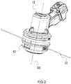
FIG. 2 is a perspective view of a partial structure of the grass trimmer ofFIG. 1 . -
FIG. 3 is an exploded view of the partial structure of the grass trimmer ofFIG. 1 . -
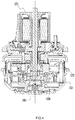
FIG. 4 is a sectional view of the partial structure of the grass trimmer ofFIG. 1 . -
FIG. 5 is a perspective view of the partial structure of the grass trimmer ofFIG. 1 . -
FIG. 6 is a perspective view of the partial structure of the grass trimmer ofFIG. 1 . -
FIG. 7 is a front view of the spool of the grass trimmer ofFIG. 1 , where the elastic members are all in the first form. -
FIG. 8 is a front view of the spool of the grass trimmer ofFIG. 1 , where the elastic members are partially in the second form. -
FIG. 9 is a schematic view of the partial structure of the spool and the clutch mechanism of the grass trimmer according to a second embodiment of this application. -
FIG. 10 is a perspective view of the spool of the grass cutting head according to a third embodiment of this application. -
FIG. 11 is a front view of the spool of the grass trimmer ofFIG. 10 , where the elastic members are all in the first form. -
FIG. 12 is a front view of the spool of the grass trimmer ofFIG. 10 , where the elastic members are partially in the second form. -
FIG. 13 is a schematic view of the spool, the head housing, and the clutch mechanism of the grass trimmer according to a fourth embodiment of this application. -
FIG. 1 is a schematic view of agrass trimmer 100 according to a first embodiment of this application. In this application, the winding method of thegrass trimmer 100 may be manual winding or automatic winding, or one of the multiple winding methods switched according to actual operation scenarios. Thegrass trimmer 100 has a grass trimming mode, a winding mode, and a cord releasing mode. The three modes correspond to grass trimming, winding, and the pay-off operation, respectively. - As illustrated in
FIG. 1 andFIG. 2 , thegrass trimmer 100 includes agrass cutting cord 11, agrass cutting head 12, and adriving mechanism 13. Thegrass cutting head 12 is configured to cooperate with thegrass cutting cord 11 to trim the grass. Thedriving mechanism 13 drives thegrass cutting head 12 to rotate in a first rotational direction with arotational axis 101 as an axis. Thegrass trimmer 100 further includes ashield 14 for preventing grass clippings from being splashed and ahandle 15 for the user to operate. - As illustrated in
FIG. 3 andFIG. 4 , thedriving mechanism 13 includes amotor 131 and amotor housing 132. Themotor 131 is configured to drive thegrass cutting head 12 to rotate in the first rotational direction with therotational axis 101 as the axis. Thegrass cutting head 12 includes ahead housing 121, a spool orbobbin 122, and aclutch mechanism 123. Thehead housing 121 includes anupper cover 121a and alower cover 121b that are detachably connected. Theupper cover 121a and thelower cover 121b surround to form an accommodation space for accommodating thespool 122 and athreading hole 121c through which thegrass cutting cord 11 passes. Thespool 122 is provided with a windingportion 122a on which lines are wound. - The
clutch mechanism 123 is configured to achieve power transmission between thehead housing 121 and thespool 122. Theclutch mechanism 123 has at least two states which are a first state and a second state. In the case where theclutch mechanism 123 is in the first state, thehead housing 121 and thespool 122 rotate together in the first rotational direction with therotational axis 101 as the axis. - In the case where the
clutch mechanism 123 is in the second state, thespool 122 rotates in the first rotational direction relative to thehead housing 121 or a second rotational direction relative to thehead housing 121. That is, in the case where theclutch mechanism 123 is in the second state, thespool 122 rotates relative to thehead housing 121 and the relative rotational direction may be the first direction or the second direction. Alternatively, thespool 122 may rotate in the first direction relative to thehead housing 121 or the second direction relative to thehead housing 121. Whether thespool 122 rotates in the second rotational direction relative to thehead housing 121 or the first rotational direction relative to thehead housing 121, the winding operation can be achieved as long as thespool 122 rotates relative to thehead housing 121. - In an embodiment, in the case where the
grass cutting head 12 is in the normal grass trimming mode, theclutch mechanism 123 is in the first state; and in the case where thegrass cutting head 12 is in the winding mode, theclutch mechanism 123 is in the second state. As illustrated inFIG. 3 , theclutch mechanism 123 includes anelastic member 123a which is elastically-deformable. In the case where theclutch mechanism 123 is in the first state, theelastic member 123a is in the first form; and in the case where theclutch mechanism 123 is in the second state, theelastic member 123a is in the second form. That is, in the case where thegrass cutting head 12 is switched from the grass trimming mode to the winding mode, the shape of theelastic member 123a of theclutch mechanism 123 changes. - The
grass cutting head 12 further includes a biasingmember 124 that generates a biasing force capable of driving theclutch mechanism 123 to move toward the first state. That is, the biasing force generated by the biasingmember 124 makes theclutch mechanism 123 be in the first state or move theclutch mechanism 123 to the first state so that thespool 122 is driven to not rotate relative to thehead housing 121. - The biasing
member 124 generates the biasing force against thespool 122 or thehead housing 121, that is, this biasing force generates a component force in a direction parallel to therotational axis 101. In an embodiment, the biasingmember 124 is a coil spring disposed in a direction of therotational axis 101 or the direction parallel to therotational axis 101, and the coil spring is fixedly connected to thelower cover 121b of thehead housing 121. In other embodiments, the structure of the biasingmember 124 is not limited to a spring structure, but may also be other structural members that are elastically-deformable, as long as the biasingmember 124 is capable of generating the biasing force against thehead housing 121 or thespool 122 and thehead housing 121 moves in an axial direction relative to thespool 122. - In an embodiment, the
grass trimmer 100 further has a cord releasing mode. In the case where thegrass trimmer 11 is damaged, thehead housing 121 or thespool 122 needs to be rotated so that a newgrass cutting cord 11 is released. In the related art, the commonly used pay-off method is automatic pay-off. In the automatic pay-off, thehead housing 121 moves in the axial direction relative to thespool 122, thehead housing 121 and thespool 122 rotate in the first direction around therotational axis 101, and thegrass cutting cord 11 is thrown out of thespool 122 through thethreading hole 121c by the centrifugal force. Through the design of the biasingmember 124, thehead housing 121 of thegrass trimmer 100 may be made to move in the axial direction relative to thespool 122 in the case where the user hits thehead housing 121 to the ground so that the automatic pay-off can be achieved. In an embodiment, the biasingmember 124 generates the biasing force against thespool 122 or thehead housing 121 in the case where thegrass trimmer 100 is in the grass trimming mode, winding mode, and cord releasing mode. Alternatively, the biasingmember 124 generates the biasing force against thespool 122 or thehead housing 121 only in the case where thegrass trimmer 100 is in the cord releasing mode. Alternatively, the biasingmember 124 generates the biasing force against thespool 122 or thehead housing 121 only in the case where thegrass trimmer 100 is in the cord releasing mode and the winding mode. - In this embodiment, the biasing
member 124 generates the biasing force against thespool 122 or thehead housing 121 in the case where thegrass trimmer 100 is in the grass trimming mode, winding mode, and cord releasing mode. The first end of the biasingmember 124 is fixedly connected to thehead housing 121, the second end of the biasingmember 124 is in contact with thespool 122, and the biasingmember 124 generates the biasing force against both thehead housing 121 and thespool 122. In an embodiment, the first end of the biasingmember 124 may also be fixedly connected to thespool 122, and the second end of the biasingmember 124 is in contact with thehead housing 121. - The
elastic member 123a is deformed in the direction parallel to therotational axis 101 when changing from the first form to the second form. In an embodiment, in the case where theclutch mechanism 123 is switched from the first state to the second state, thehead housing 121 moves in the direction parallel to therotational axis 101 relative to thespool 122. In the related art, theclutch mechanism 123 is not provided with theelastic member 123a. In this manner, in the case where theclutch mechanism 123 is switched from the first state to the second state, the relative displacement of thehead housing 121 with respect to thespool 122 in the direction parallel to therotational axis 101 comes from the elastic displacement of the further compressed biasingmember 124 in this direction. The difference of this embodiment is that the relative displacement of thehead housing 121 with respect to thespool 122 in the direction parallel to therotational axis 101 comes from the elastic deformation of theelastic member 123a in this direction or at least part of the relative displacement comes from the elastic deformation of theelastic member 123a in this direction. In this embodiment, the entire relative displacement of thehead housing 121 with respect to thespool 122 in the direction parallel to therotational axis 101 basically comes from the elastic deformation of theelastic member 123a in this direction. In other embodiments, the biasingmember 124 also moves in the direction parallel to therotational axis 101 in the case where thegrass cutting head 12 performs the winding. That is, in the case where the winding is performed, the relative displacement of thehead housing 121 with respect to thespool 122 in the direction parallel to therotational axis 101 may be provided by the elastic displacement of theelastic member 123a and the elastic displacement of the biasingmember 124. - In the case where the
clutch mechanism 123 is in the second state, part of the rotational torsion force received by thespool 122 or thehead housing 121 is configured to resist the elastic force generated by theelastic member 123a. In the case where thegrass cutting head 12 is in the winding mode, theclutch mechanism 123 is in the second state, theelastic member 123a is in the second state, and the relative rotation of thespool 122 or thehead housing 121 is caused by the rotational torsion force. In this case, theelastic member 123a generates a component force whose direction is opposite to the direction of the rotational torsion force, part of the rotational torsion force is configured to overcome this component force, and the other part of the rotational torsion force is configured to drive thespool 122 and thehead housing 121 to rotate relative to each other. - As illustrated in
FIG. 5 to FIG. 8 , theclutch mechanism 123 further includes a cooperatingportion 123b configured to cooperate with theelastic member 123a to transmit power. Theelastic member 123a is disposed on one of thespool 122 or thehead housing 121, and the cooperatingportion 123b is disposed on the other one of thespool 122 or thehead housing 121. In this embodiment, theelastic member 123a is disposed on thespool 122, and the cooperatingportion 123b is disposed on thehead housing 121 and is disposed in theupper cover 121a of thehead housing 121. As illustrated inFIG. 6 , theelastic member 123a is provided with a driving surface 11'. The driving surface 11' is substantially perpendicular to the end surface of thespool 122. In the case where theelastic member 123a is in the first form, the driving surface 11' drives the cooperatingportion 123b to rotate along with theelastic member 123a in the first rotational direction. That is, in the case where theelastic member 123a is in the first form, the driving surface 11' of theelastic member 123a is configured to drive thehead housing 121 to rotate together with thespool 122 in the first rotational direction. Specifically, the first direction is a clockwise direction or a counterclockwise direction around therotational axis 101. - The
elastic member 123a is further provided with an elastic surface 12'. The elastic surface 12' allows the cooperatingportion 123b to rotate in the second rotational direction relative to theelastic member 123a in the case where theelastic member 123a is in the second form. As illustrated inFIG. 6 and FIG. 7 , the elastic surface 12' includes a first ramp 121' that forms a preset angle with thespool 122 and is tilted upward. In this embodiment, the elastic surface 12' further includes a downward-tilted second ramp 122'. The first end of the second ramp 122' is connected to the first ramp 121' and the second end of the second ramp 122' is connected to the driving surface 11'. The cooperatingportion 123b is provided with structures that cooperate with the driving surface 11' and the elastic surface 12', respectively. In an embodiment, the driving surface 11' and the elastic surface 12' of theelastic member 123a may be a planar surface or a curved surface. Specifically, the second direction is a counterclockwise direction opposite to the first direction or a clockwise direction opposite to the first direction around therotational axis 101. - The first end of the
elastic member 123a is fixedly connected to one end surface of thespool 122. The second end of theelastic member 123a is suspended in the air. Theelastic member 123a extends obliquely upward in the circumferential direction of thespool 122, and a preset angle is formed by theelastic member 123a and the end surface of thespool 122. In an embodiment, theelastic member 123a may also be integrally formed with thespool 122. In this embodiment, theelastic member 123a is a metal elastic piece. In other embodiments, theelastic member 123a may be a plastic elastic piece.FIG. 7 is a planar view of theelastic member 123a in the first form.FIG. 8 is a planar view of theelastic member 123a in the second form. Theelastic member 123a is deformed in the direction parallel to therotational axis 101 when changing from the first form to the second form. For ease of description, the up and down directions are set inFIG. 7 . The metal elastic piece is deformed downward in the direction parallel to therotational axis 101 after acted by a force. In addition, in this embodiment, six metal elastic pieces are uniformly disposed in the circumferential direction on the surface of thespool 122, but the number and material of the elastic pieces are not specifically limited in this embodiment. - As illustrated in
FIG. 6 and FIG. 7 , the height c of the driving surface 11' perpendicular to the end surface of thespool 122 is about 2 mm, the length a of the first ramp 121' of theelastic member 123a is about 25 mm, and the length b of the first ramp 122' of theelastic member 123a is about 5 mm. The acute angle α formed by the first ramp 121' of theelastic member 123a and the end surface of thespool 122 is about 60°, and the acute angle β formed by the second ramp 122' of theelastic member 123a and the end surface of thespool 122 is approximately 5°. This embodiment does not limit the specific structure of theelastic member 123a. In fact, the preceding parameter settings, especially the oblique angle formed by the first ramp 121' of theelastic member 123a and the end surface of thespool 122 and the oblique angle formed by the second ramp 122' of theelastic member 123a and the end surface of thespool 122 greatly reduce the load of thegrass trimmer 100 when performing the winding, thereby reducing the power consumption of themotor 131. In this embodiment, the output power of thegrass trimmer 100 when performing the winding is less than or equal to 529 W. Comparing the grass trimmer in this embodiment with the grass trimmer using a clutch mechanism with the same size as the clutch mechanism in this embodiment but not elastically-deformable, the reduction in the output power of themotor 131 in the case where the winding is performed is greater than or equal to 30% in this embodiment. - In this embodiment, the driving surface 11' of the
elastic member 123a is substantially perpendicular to the end surface of thespool 122. Therefore, in the case where theclutch mechanism 123 is in the second state, it is basically allowed that thespool 122 rotates in the second rotational direction opposite to the first rotational direction relative to thehead housing 121. - In the grass trimmer and the grass cutting head of this grass trimmer provided in this embodiment, a deformable clutch structure between the housing and the spool is adopted so that the load in the case where the winding is performed can be greatly reduced and it can be easier and labor-saving for the user to perform the winding. Therefore, the practicability of the grass cutting head can be improved.
-
FIG. 9 is a schematic view of the partial structure of thespool 222 and the clutch mechanism according to a second embodiment of this application. The difference between this embodiment and the first embodiment lies in the structure of the clutch mechanism. The parts in the first embodiment and applicable to this embodiment may be applied to this embodiment, and only the difference between this embodiment and the first embodiment is described below. The driving surface 21' of theelastic member 223a is disposed at a non-zero acute angle to the vertical direction. In an embodiment, the driving surface 21' of theelastic member 223a is obliquely downward with respect to the vertical direction and forms an acute angle n as shown inFIG. 9 with the upper-end surface 222a of thespool 222. The cooperating portion (not marked in the figure) is further provided with a ramp parallel to the driving surface 21'. The driving surface 21' and the ramp on the cooperating portion match each other in the case where the clutch mechanism is in the first state. The driving surface 21' drives the cooperating portion to rotate in the first rotational direction. In this case, the driving force in the first rotational direction received by thespool 222 is not large enough to cause the relative displacement between the driving surface 21' and the cooperating portion. In the case where the clutch mechanism is in the second state, thespool 222 receives a large enough driving force in the first rotational direction so that the relative displacement between the driving surface 21' and the cooperating portion occurs and the driving surface 21' rotates in the first rotational direction relative to the cooperating portion. In an embodiment, the structures of the other parts of theelastic member 223a are the same as those illustrated inFIGS. 5 to 8 . Therefore, in this embodiment, thespool 222 can also rotate in the second rotational direction opposite to the first rotational direction relative to the head housing. That is, in this embodiment, in the case where the clutch structure is in the second state, thespool 222 can rotate in the first direction or the second direction relative to the head housing. -
FIGS. 10 to 12 are structure views of thespool 322 and theelastic member 323a of the grass cutting head according to a third embodiment of this application. The differences between this embodiment and the first embodiment only line in the structures of theelastic member 323a and thespool 322. The parts in the first embodiment and applicable to this embodiment may be applied to this embodiment, and only the differences between this embodiment and the first embodiment are described below. -
FIG. 11 is a planar view of theelastic member 323a in the first form.FIG. 12 is a planar view of theelastic member 323a in the second form. Theelastic member 323a is deformed in the direction parallel to therotational axis 301 when changing from the first form to the second form. In this embodiment, theelastic member 323a of theclutch mechanism 323 is a metal elastic piece, and three metal elastic pieces are uniformly disposed in the circumferential direction on the surface of thespool 322. Similarly, the number of the elastic pieces in this embodiment is not limited. In an embodiment, as long as the number of the elastic pieces is greater than or equal to 1, the function of theclutch mechanism 323 can be achieved. In this embodiment, theelastic member 323a is provided with a driving surface 31'. This driving surface 31' is configured to drive the cooperating portion (not marked in the figure) to rotate with theelastic member 323a in the case where theelastic member 323a is in the first form. This driving surface 31' is perpendicular to the end surface of thespool 322. Theelastic member 323a is further provided with an elastic surface 32'. This elastic surface 32' is configured to allow the cooperating portion to rotate relative to theelastic member 323a in the case where theelastic member 323a is in the second form. The elastic surface 32' includes a first ramp 321' that forms a preset angle with thespool 322 and is tilted upward. In this embodiment, the elastic surface 32' further includes a second ramp 322' that is tilted downward. The first end of theelastic member 323a is fixedly connected to one end surface of thespool 322. The second end of theelastic member 323a is provided with aflange 323b. Theflange 323b extends to the inside of thespool 322. In the case where theelastic member 323a is in the first form, theflange 323b abuts or is in contact with thespool 322 on a plane parallel to the end surface of thespool 322 to prevent theelastic member 323a from moving upward along with the cooperating portion in the case where the grass trimmer is in the cord releasing mode. In the case where theelastic member 323a is in the first form, theflange 323b is not in contact with thespool 322 on a plane parallel to the end surface of thespool 322. In the case where theelastic member 323a moves upward by a preset distance, theflange 323b abuts thespool 322 to prevent theelastic member 323a from moving excessively upward. In an embodiment, theflange 323b only needs to be capable of preventing theelastic member 323a from moving excessively upward in the direction parallel to therotational axis 301. That is, the following case is avoided: due to the excessive friction between theelastic member 323a and the cooperating portion, the relative displacement between thespool 322 and the head housing in the direction parallel to therotational axis 301 does not occur. -
FIG. 13 is a schematic view of thespool 422 and thehead housing 421 of the grass cutting head according to a fourth embodiment of this application. The difference between this embodiment and the previous three embodiments lies in the structure and working principle of the clutch mechanism. In this embodiment, the clutch mechanism includes a first magnetic component and a second magnetic component. The first magnetic component is disposed on one of thehead housing 421 or thespool 422, and the second magnetic component is disposed on the other one of thehead housing 421 or thespool 422. A magnetic force is formed between the first magnetic component and the second magnetic component. In the case where the clutch mechanism is in the second state, the repulsive force between the first magnetic component and the second magnetic component is greater than the attractive force between the first magnetic component and the second magnetic component. The first magnetic component disposed on thespool 422 includes at least one firstmagnetic element 423a, and the second magnetic component disposed in thehead housing 421 includes at least one secondmagnetic element 423b. The firstmagnetic element 423a and the secondmagnetic element 423b are made of magnetic materials. In the case where the clutch mechanism is in the second state, the firstmagnetic element 423a and the secondmagnetic element 423b match each other and have opposite magnetic poles, respectively. - In this embodiment, the first
magnetic element 423a is approximately in the shape of an oblique block. The firstmagnetic element 423a is provided with aramp 423c. The magnetic pole where theramp 423c is located is the N-pole or S-pole. The magnetic pole of the bottom surface of the firstmagnetic element 423a opposite to theramp 423c is opposite to the magnetic pole of theramp 423c. The secondmagnetic element 423b is provided with amatching ramp 423d that matches with theramp 423c of the first magnetic component. The magnetic pole of thematching ramp 423d is opposite to the magnetic pole of theramp 423c of the first magnetic component. In this manner, in the case where the clutch mechanism is in the second state, the repulsive force between the first magnetic component and the second magnetic component is greater than the attractive force between the first magnetic component and the second magnetic component, and the repulsive force between the opposite magnetic poles contributes a part of the force that presses the biasingmember 124 downward so that the load in the case where the winding is performed can be reduced. The firstmagnetic element 423a further includes a driving surface 423e. The driving surface 423e is substantially perpendicular to the upper-end surface of thespool 422. The secondmagnetic element 423b is provided with a drivensurface 423f that matches with the driving surface 423e. In the case where the clutch mechanism is in the first state, the driving surface 423e drives the drivensurface 423f to rotate with therotational axis 401 as the axis. - In this application, the structure of the clutch mechanism is not limited to the structure shown in the preceding four embodiments. In an embodiment, an oblique wedge made of elastic materials may be disposed on the surface of the spool as an elastic member, and this oblique wedge may be molded onto the surface of the spool by over-injection. In other embodiments, both the head housing and the spool may be provided with elastically-deformable elastic structures that match each other. That is, the elastic member and the cooperating portion are elastically deformed in the case where the winding is performed. To sum up, any clutch structure which is elastically-deformable in the direction parallel to the rotational axis in the case where the grass cutting head performs the winding is within the scope of this application.
Claims (15)
- A grass trimmer, comprising:a grass cutting head configured to cut grass; anda driving mechanism configured to drive the grass cutting head to rotate in a first rotational direction around a rotational axis;wherein the grass cutting head comprises:a head housing;a spool comprising a winding portion; anda clutch mechanism configured to implement power transmission between the head housing and the spool, wherein the clutch mechanism has a first state by which the head housing and the spool are operative to rotate synchronously and a second state by which the spool is operative to rotate in the first rotational direction relative to the head housing or in a second rotational direction opposite to the first rotational direction relative to the head housing,wherein the clutch mechanism comprises an elastic member which is elastically deformable, and the elastic member has at least a first form and a second form; andwherein the elastic member is configured to be in the first form in a case where the clutch mechanism is in the first state; and is further configured to be in the second form in a case where the clutch structure is in the second state.
- The grass trimmer of claim 1, further comprising a biasing member configured to generate a biasing force that drives the clutch mechanism to move toward the first state.
- The grass trimmer of claim 2, wherein the biasing member is configured to generate the biasing force in a direction parallel to the rotational axis of the grass cutting head; and the elastic member is configured to be deformed in the direction parallel to the rotational axis in the process of changing from the first form to the second form.
- The grass trimmer of claim 3, wherein the biasing member is a coil spring arranged along the rotational axis or parallel to the rotational axis.
- The grass trimmer of claim 1, further comprising a biasing member, wherein the biasing member is configured to generate a biasing force against the spool or the head housing; and
in the case where the clutch mechanism is in the second state, a rotational torsion force the spool or the head housing is subjected to is at least partially configured to resist an elastic force generated by the elastic member. - The grass trimmer of claim 1, further comprising a biasing member, wherein the biasing member is configured to generate a biasing force against the spool or the head housing in the case where the clutch mechanism is in the second state; and the elastic member is configured to generate an elastic force against the spool or the head housing in the case where the clutch mechanism is in the second state.
- The grass trimmer of claim 1, wherein the elastic member is integrally formed with the spool or the elastic member is integrally formed with the head housing.
- The grass trimmer of claim 1, wherein the elastic member is arranged on the spool or the head housing.
- The grass trimmer of claim 8, wherein the clutch mechanism further comprises a cooperating portion configured to cooperate with the elastic member to transmit power.
- The grass trimmer of claim 9, wherein the elastic member is arranged on the spool, and the cooperating portion is disposed on the head housing; or the elastic member is disposed on the head housing, and the cooperating portion is disposed on the spool; and
wherein the elastic member comprising a driving surface and an elastic surface, the driving surface is configured to drive the cooperating portion to rotate with the elastic member in a case where the elastic member is in the first form, and the elastic surface is configured to cause the cooperating portion to rotate relative to the elastic member in a case where the elastic member is in the second form. - A grass cutting head, comprising:a head housing;a spool provided with a winding portion; anda clutch mechanism configured to implement power transmission between the head housing and the spool, wherein the clutch mechanism has a first state by which the head housing and the spool are operative to rotate together and a second state by which the spool is operative to rotate in a first rotational direction relative to the head housing or in a second rotational direction opposite to the first rotational direction relative to the head housing,wherein the clutch mechanism comprises an elastic member which is elastically-deformable, and the elastic member has a first form and a second form; andwherein the elastic member is configured to be in the first form in a case where the clutch mechanism is in the first state; and the elastic member is further configured to be in the second form in a case where the clutch structure is in the second state.
- The grass cutting head of claim 11, further comprising a biasing member configured to generate a biasing force that drives the clutch mechanism to move toward the first state.
- The grass cutting head of claim 12, wherein the biasing member is configured to generate the biasing force in a direction parallel to a rotational axis of the grass cutting head; and the elastic member is configured to be deformed in the direction parallel to the rotational axis in the process of changing from the first form to the second form.
- A grass trimmer, comprising:a grass cutting head configured to cut grass; anda driving mechanism configured to drive the grass cutting head to rotate in a first rotational direction around a rotational axis,wherein the grass cutting head comprises:a head housing;a spool comprising a winding portion; anda clutch mechanism configured to implement power transmission between the head housing and the spool, wherein the clutch mechanism has a first state by which the head housing and the spool are operative to rotate together and a second state by which the spool is operative to rotate in a second rotational direction opposite to the first rotational direction relative to the head housing,wherein the clutch mechanism comprises a first magnetic component and a second magnetic component, and wherein the first magnetic component is disposed in the head housing, and the second magnetic component is disposed on the spool; orthe first magnetic component is disposed on the spool, and the second magnetic component is disposed in the head housing,wherein there is created a magnetic force between the first magnetic component and the second magnetic component, the first magnetic component is configured such that a repulsive force between the first magnetic component and the second magnetic component is greater than an attractive force between the first magnetic component and the second magnetic component in a case where the clutch mechanism is in the second state.
- The grass trimmer of claim 14, wherein the first magnetic component is further configured such that the attractive force between the first magnetic component and the second magnetic component is greater than the repulsive force between the first magnetic component and the second magnetic component in a case where the clutch mechanism is in the first state.
Applications Claiming Priority (2)
| Application Number | Priority Date | Filing Date | Title |
|---|---|---|---|
| CN201810891350 | 2018-08-07 | ||
| PCT/CN2019/096982 WO2020029776A1 (en) | 2018-08-07 | 2019-07-22 | Grass trimmer head and grass trimmer comprising the grass trimmer head |
Publications (2)
| Publication Number | Publication Date |
|---|---|
| EP3811755A1 true EP3811755A1 (en) | 2021-04-28 |
| EP3811755A4 EP3811755A4 (en) | 2021-09-08 |
Family
ID=69413779
Family Applications (1)
| Application Number | Title | Priority Date | Filing Date |
|---|---|---|---|
| EP19845993.5A Withdrawn EP3811755A4 (en) | 2018-08-07 | 2019-07-22 | GRASS CUTTER HEAD AND GRASS CUTTER WITH GRASS CUTTER HEAD |
Country Status (5)
| Country | Link |
|---|---|
| US (1) | US11089725B2 (en) |
| EP (1) | EP3811755A4 (en) |
| CN (3) | CN110809987B (en) |
| CA (1) | CA3108590C (en) |
| WO (1) | WO2020029776A1 (en) |
Families Citing this family (13)
| Publication number | Priority date | Publication date | Assignee | Title |
|---|---|---|---|---|
| US9924631B2 (en) | 2008-04-22 | 2018-03-27 | George E. Alliss | Spool for straight through line feed vegetation trimmer apparatus with modules and spokes |
| USD970321S1 (en) * | 2014-11-20 | 2022-11-22 | Torvent Llc | Line trimmer component |
| US11818979B2 (en) * | 2016-01-22 | 2023-11-21 | Nanjing Chervon Industry Co., Ltd. | Grass trimmer |
| CN110809987B (en) * | 2018-08-07 | 2025-03-18 | 南京泉峰科技有限公司 | Grass trimmer head and grass trimmer including the grass trimmer head |
| EP3785518B1 (en) * | 2019-08-30 | 2023-07-05 | Andreas Stihl AG & Co. KG | Thread mower head for mounting on a drive shaft of a brush cutter |
| US12133482B2 (en) * | 2019-09-17 | 2024-11-05 | Nanjing Chervon Industry Co., Ltd. | Trimmer head and string trimmer |
| US11452258B2 (en) * | 2020-01-07 | 2022-09-27 | Nanjing Chervon Industry Co., Ltd. | Grass trimmer |
| CN112753352B (en) * | 2021-01-13 | 2021-10-22 | 郑州航空工业管理学院 | Intelligent municipal garden collection device that mows |
| US12201057B2 (en) * | 2021-03-15 | 2025-01-21 | Nanjing Chervon Industry Co., Ltd. | Grass trimmer |
| USD988101S1 (en) * | 2021-07-01 | 2023-06-06 | Huajie Dong | Handheld lawn mower |
| USD1101524S1 (en) * | 2022-08-25 | 2025-11-11 | Nanjing Chervon Industry Co., Ltd. | String trimmer head |
| USD1074340S1 (en) * | 2023-02-20 | 2025-05-13 | Zhejiang Guyuehu Industry and Trade Co., Ltd. | Grass trimmer |
| USD1074341S1 (en) * | 2023-02-20 | 2025-05-13 | Zhejiang Guyuehu Industry and Trade Co., Ltd. | Grass trimmer |
Family Cites Families (26)
| Publication number | Priority date | Publication date | Assignee | Title |
|---|---|---|---|---|
| US4161820A (en) * | 1977-10-28 | 1979-07-24 | Weed Eater, Inc. | Apparatus for cutting vegetation |
| US4183138A (en) * | 1978-03-08 | 1980-01-15 | Weed Eater, Inc. | Apparatus for cutting vegetation |
| EP0005540B1 (en) * | 1978-05-24 | 1982-04-21 | Wolf-Geräte GmbH | Cutting wire for trimming lawn borders |
| DE2828425A1 (en) * | 1978-06-28 | 1980-01-10 | Stihl Maschf Andreas | PLANT CUTTER |
| US4295327A (en) * | 1980-06-05 | 1981-10-20 | Bortolussi Everest J | Magnetic safety clutch for rotary lawnmower |
| US4419822A (en) * | 1981-01-14 | 1983-12-13 | Black & Decker Inc. | Bump-feed trimmer |
| US4490910A (en) * | 1982-07-21 | 1985-01-01 | Allegretti & Co. | Cutting head for string trimmer |
| US4702005A (en) * | 1984-06-29 | 1987-10-27 | Pittinger Sr Charles B | Apparatus for cutting vegetation with incremental feeding of cutting filament |
| US4817288A (en) * | 1986-03-25 | 1989-04-04 | Daijo Hirose | Cutting head for cord type mower |
| TW476720B (en) * | 1999-06-04 | 2002-02-21 | Sunstar Engineering Inc | Power assisted bicycle |
| US6952877B2 (en) * | 2003-01-10 | 2005-10-11 | Shindaiwa, Inc. | Vegetation cutting device |
| US8266805B1 (en) * | 2004-05-11 | 2012-09-18 | George Everett Alliss | String trimmer head having invertible components that enable selective clockwise and counterclockwise operations |
| CN2731956Y (en) * | 2004-09-22 | 2005-10-12 | 苏州宝时得电动工具有限公司 | Electric tool |
| US7882642B2 (en) * | 2006-09-01 | 2011-02-08 | Proulx Manufacturing, Inc. | Trimmer head for use in flexible line rotary trimmers having improved line loading mechanism |
| JP2010119353A (en) * | 2008-11-20 | 2010-06-03 | Isao Kohama | Rotary case equipped with mechanism for delivering nylon cutter for mower |
| CN103202136A (en) * | 2012-01-11 | 2013-07-17 | 杨健 | Grass cutting machine with automatic clutch |
| JP5961544B2 (en) * | 2012-12-20 | 2016-08-02 | 株式会社マキタ | Portable work machine |
| US20180020615A1 (en) * | 2013-11-22 | 2018-01-25 | George E. Alliss | Easy load trimmer head spool with non-radial guide channel |
| CN203934334U (en) * | 2014-05-16 | 2014-11-12 | 苏州宝时得电动工具有限公司 | Mower |
| US10130030B2 (en) * | 2014-05-27 | 2018-11-20 | Mtd Products Inc | Trimmer head |
| US10202165B2 (en) * | 2015-08-06 | 2019-02-12 | Shimano Inc. | Bicycle wheel-securing axle |
| CN106993426B (en) * | 2016-01-22 | 2019-03-08 | 南京德朔实业有限公司 | lawn mower |
| CA3012335A1 (en) * | 2016-02-22 | 2017-08-31 | Mtd Products Inc | Multi-mode trimmer head |
| CN205555716U (en) * | 2016-03-23 | 2016-09-07 | 重庆市南方阻燃电线电缆有限公司 | Self -adaptation wire reel device that anti external force was disturbed |
| CN106922276A (en) * | 2017-03-22 | 2017-07-07 | 杭州富阳鸿祥技术服务有限公司 | A self-adaptive laminated weeder for municipal landscape engineering |
| CN110809987B (en) * | 2018-08-07 | 2025-03-18 | 南京泉峰科技有限公司 | Grass trimmer head and grass trimmer including the grass trimmer head |
-
2019
- 2019-06-20 CN CN201910536140.3A patent/CN110809987B/en active Active
- 2019-06-20 CN CN201920937923.8U patent/CN211020027U/en not_active Withdrawn - After Issue
- 2019-07-22 CN CN201980007516.XA patent/CN111867356A/en not_active Withdrawn
- 2019-07-22 EP EP19845993.5A patent/EP3811755A4/en not_active Withdrawn
- 2019-07-22 WO PCT/CN2019/096982 patent/WO2020029776A1/en not_active Ceased
- 2019-07-22 CA CA3108590A patent/CA3108590C/en not_active Expired - Fee Related
-
2021
- 2021-01-25 US US17/156,969 patent/US11089725B2/en not_active Expired - Fee Related
Also Published As
| Publication number | Publication date |
|---|---|
| CN110809987A (en) | 2020-02-21 |
| WO2020029776A1 (en) | 2020-02-13 |
| US20210137004A1 (en) | 2021-05-13 |
| CA3108590C (en) | 2021-11-23 |
| CN211020027U (en) | 2020-07-17 |
| US11089725B2 (en) | 2021-08-17 |
| EP3811755A4 (en) | 2021-09-08 |
| CA3108590A1 (en) | 2020-02-13 |
| CN110809987B (en) | 2025-03-18 |
| CN111867356A (en) | 2020-10-30 |
Similar Documents
| Publication | Publication Date | Title |
|---|---|---|
| CA3108590C (en) | Grass cutting head and grass trimmer comprising the grass trimmer head | |
| CN111629583B (en) | Grass mowing head and grass mowing machine adopting grass mowing head | |
| JP5394895B2 (en) | Electric tool | |
| US20230041828A1 (en) | Working machine | |
| US20230014201A1 (en) | Trimming machine | |
| EP3821697A1 (en) | Pruning machine | |
| WO2015144197A1 (en) | Quick loading trimmer head | |
| CA3021508C (en) | Low-energy blade system having a quick-attach mechanism | |
| CN210183903U (en) | Movable mowing robot with cutter head capable of being replaced quickly | |
| AU2021100227A4 (en) | Grass cutting head and grass trimmer including the same | |
| DE212022000148U1 (en) | Hand-held power tool | |
| US20230086452A1 (en) | Torque output tool and control method for a torque output tool | |
| EP2923549B1 (en) | Quick loading trimmer head | |
| CN222840984U (en) | Side brush assembly and cleaning equipment | |
| KR102177849B1 (en) | Electric Scissors | |
| CN111133880B (en) | Grass trimmer | |
| DE102022108918A1 (en) | ELECTRICAL WORK EQUIPMENT AND METHOD OF MANUFACTURE THE SAME | |
| CN220748577U (en) | Detachable connection structure of fan blades and portable rechargeable tent fan | |
| CN111149505B (en) | a lawnmower | |
| CN210246527U (en) | Brushless motor of mower and control handle structure | |
| CN112514632B (en) | Grass trimmer head and grass trimmer using the grass trimmer head | |
| CN213214367U (en) | Grass mowing head and grass mowing machine | |
| JP2023183526A (en) | Brushless motor, electric working machine, and brushless motor manufacturing method | |
| JP6713877B2 (en) | Cutting blade | |
| EP4525277B1 (en) | Motor bearing shield |
Legal Events
| Date | Code | Title | Description |
|---|---|---|---|
| STAA | Information on the status of an ep patent application or granted ep patent |
Free format text: STATUS: THE INTERNATIONAL PUBLICATION HAS BEEN MADE |
|
| PUAI | Public reference made under article 153(3) epc to a published international application that has entered the european phase |
Free format text: ORIGINAL CODE: 0009012 |
|
| STAA | Information on the status of an ep patent application or granted ep patent |
Free format text: STATUS: REQUEST FOR EXAMINATION WAS MADE |
|
| 17P | Request for examination filed |
Effective date: 20210121 |
|
| AK | Designated contracting states |
Kind code of ref document: A1 Designated state(s): AL AT BE BG CH CY CZ DE DK EE ES FI FR GB GR HR HU IE IS IT LI LT LU LV MC MK MT NL NO PL PT RO RS SE SI SK SM TR |
|
| AX | Request for extension of the european patent |
Extension state: BA ME |
|
| A4 | Supplementary search report drawn up and despatched |
Effective date: 20210806 |
|
| RIC1 | Information provided on ipc code assigned before grant |
Ipc: A01D 34/62 20060101ALI20210802BHEP Ipc: A01D 34/416 20060101AFI20210802BHEP |
|
| DAV | Request for validation of the european patent (deleted) | ||
| DAX | Request for extension of the european patent (deleted) | ||
| STAA | Information on the status of an ep patent application or granted ep patent |
Free format text: STATUS: EXAMINATION IS IN PROGRESS |
|
| 17Q | First examination report despatched |
Effective date: 20220225 |
|
| STAA | Information on the status of an ep patent application or granted ep patent |
Free format text: STATUS: THE APPLICATION HAS BEEN WITHDRAWN |
|
| 18W | Application withdrawn |
Effective date: 20220523 |