EP3811115B1 - Vehicule automobile equipe de capteurs anticollisions - Google Patents
Vehicule automobile equipe de capteurs anticollisions Download PDFInfo
- Publication number
- EP3811115B1 EP3811115B1 EP19742641.4A EP19742641A EP3811115B1 EP 3811115 B1 EP3811115 B1 EP 3811115B1 EP 19742641 A EP19742641 A EP 19742641A EP 3811115 B1 EP3811115 B1 EP 3811115B1
- Authority
- EP
- European Patent Office
- Prior art keywords
- vehicle
- sensors
- detection zones
- corners
- zones
- Prior art date
- Legal status (The legal status is an assumption and is not a legal conclusion. Google has not performed a legal analysis and makes no representation as to the accuracy of the status listed.)
- Active
Links
Images
Classifications
-
- G—PHYSICS
- G01—MEASURING; TESTING
- G01S—RADIO DIRECTION-FINDING; RADIO NAVIGATION; DETERMINING DISTANCE OR VELOCITY BY USE OF RADIO WAVES; LOCATING OR PRESENCE-DETECTING BY USE OF THE REFLECTION OR RERADIATION OF RADIO WAVES; ANALOGOUS ARRANGEMENTS USING OTHER WAVES
- G01S17/00—Systems using the reflection or reradiation of electromagnetic waves other than radio waves, e.g. lidar systems
- G01S17/87—Combinations of systems using electromagnetic waves other than radio waves
-
- G—PHYSICS
- G01—MEASURING; TESTING
- G01S—RADIO DIRECTION-FINDING; RADIO NAVIGATION; DETERMINING DISTANCE OR VELOCITY BY USE OF RADIO WAVES; LOCATING OR PRESENCE-DETECTING BY USE OF THE REFLECTION OR RERADIATION OF RADIO WAVES; ANALOGOUS ARRANGEMENTS USING OTHER WAVES
- G01S17/00—Systems using the reflection or reradiation of electromagnetic waves other than radio waves, e.g. lidar systems
- G01S17/88—Lidar systems specially adapted for specific applications
- G01S17/93—Lidar systems specially adapted for specific applications for anti-collision purposes
- G01S17/931—Lidar systems specially adapted for specific applications for anti-collision purposes of land vehicles
-
- G—PHYSICS
- G01—MEASURING; TESTING
- G01S—RADIO DIRECTION-FINDING; RADIO NAVIGATION; DETERMINING DISTANCE OR VELOCITY BY USE OF RADIO WAVES; LOCATING OR PRESENCE-DETECTING BY USE OF THE REFLECTION OR RERADIATION OF RADIO WAVES; ANALOGOUS ARRANGEMENTS USING OTHER WAVES
- G01S7/00—Details of systems according to groups G01S13/00, G01S15/00, G01S17/00
- G01S7/48—Details of systems according to groups G01S13/00, G01S15/00, G01S17/00 of systems according to group G01S17/00
- G01S7/481—Constructional features, e.g. arrangements of optical elements
- G01S7/4811—Constructional features, e.g. arrangements of optical elements common to transmitter and receiver
- G01S7/4813—Housing arrangements
-
- G—PHYSICS
- G01—MEASURING; TESTING
- G01S—RADIO DIRECTION-FINDING; RADIO NAVIGATION; DETERMINING DISTANCE OR VELOCITY BY USE OF RADIO WAVES; LOCATING OR PRESENCE-DETECTING BY USE OF THE REFLECTION OR RERADIATION OF RADIO WAVES; ANALOGOUS ARRANGEMENTS USING OTHER WAVES
- G01S7/00—Details of systems according to groups G01S13/00, G01S15/00, G01S17/00
- G01S7/48—Details of systems according to groups G01S13/00, G01S15/00, G01S17/00 of systems according to group G01S17/00
- G01S7/481—Constructional features, e.g. arrangements of optical elements
- G01S7/4814—Constructional features, e.g. arrangements of optical elements of transmitters alone
- G01S7/4815—Constructional features, e.g. arrangements of optical elements of transmitters alone using multiple transmitters
-
- G—PHYSICS
- G01—MEASURING; TESTING
- G01S—RADIO DIRECTION-FINDING; RADIO NAVIGATION; DETERMINING DISTANCE OR VELOCITY BY USE OF RADIO WAVES; LOCATING OR PRESENCE-DETECTING BY USE OF THE REFLECTION OR RERADIATION OF RADIO WAVES; ANALOGOUS ARRANGEMENTS USING OTHER WAVES
- G01S7/00—Details of systems according to groups G01S13/00, G01S15/00, G01S17/00
- G01S7/48—Details of systems according to groups G01S13/00, G01S15/00, G01S17/00 of systems according to group G01S17/00
- G01S7/481—Constructional features, e.g. arrangements of optical elements
- G01S7/4817—Constructional features, e.g. arrangements of optical elements relating to scanning
Definitions
- the present invention generally relates to anti-collision sensors and relates more particularly to the installation of these sensors in vehicles equipped with an autonomous driving function, and in particular an autonomous shuttle.
- lidars are arranged respectively at the four corners of the motor vehicle.
- the document WO2017060977 discloses an information processing device comprising a plurality of light transmitting/receiving units and an information processing unit.
- Each of the light transmitting/receiving units includes an emitting unit which emits light, a scanning unit which scans the light emitted from the emitting unit, and a light receiving unit which receives light reflected from an object
- the operation request part has a margin time calculation part configured to calculate a margin time until a time when the driver should start the operation when the operation is to be requested from the driver and a part of information provision control configured to provide the driver with different information depending on the margin time.
- the document EP3081959 discloses a method for determining a respective mounting position of at least two sensors of an autonomous motor vehicle.
- the document US2018136644 discloses a system, device, or process that can be configured to implement an application that applies artificial intelligence and/or machine learning techniques to predict an optimal course of action (or a subset of action) for an autonomous vehicle system (e.g., one or more autonomous vehicle schedulers, a simulator, or a teleoperator) to be taken based on suboptimal autonomous vehicle performance and/or detected data changes from sensors (e.g. new buildings, landmarks, potholes, etc.).
- an autonomous vehicle system e.g., one or more autonomous vehicle schedulers, a simulator, or a teleoperator
- sensors e.g. new buildings, landmarks, potholes, etc.
- a lidar acronym meaning "light, or laser, detecting and ranging” is an optoelectronic system comprising a laser beam emitter, a receiver comprising a light collector and a photo detector which transforms the light into an electrical signal as well as a electronic signal processing chain that extracts the information sought.
- Such sensors use a laser beam to determine the distance which separates them from objects present in the environment of the carrying vehicle (meaning the equipped vehicle, “carrier” of said sensors). They make it possible to detect dangerous obstacles near the carrier vehicle. They are part of the start of the safety chain to trigger emergency braking in the event that a dangerous obstacle is very close to the carrier vehicle.
- the embodiment described in the present invention more particularly considers lidars of the LMS-151 type marketed by the company Sick, which are arranged at the four corners of the carrier vehicle generally at 300 mm from the ground.
- the aim of the invention is in particular to find a compromise in the installation of the sensors on the vehicle making it possible to ensure both obstacle detection essential for the safety of pedestrians and reduced overflow of the sensors with respect to the size of the vehicle. to reduce the risk of material breakage.
- a motor vehicle equipped with at least four identical anti-collision sensors, of the lidar type, arranged respectively at the four corners of the vehicle, each sensor having the same determined opening angle and defining at least one detection zone around the vehicle, certain detection zones being able to overlap to create redundancy, characterized in that the two front left and right sensors are positioned and oriented in such a way that that their detection zones tangent the offset of the left and right front wheels respectively, considering the maximum steering angle of the left and right front wheels, and in that the two left and right rear sensors define detection zones, without overlapping with other detection zones, respectively on the left and right sides of the vehicle; the detection zones without overlap tangent to the offset of the left and right front wheels considering their maximum steering angle and in which the left and right rear sensors are positioned at the rear of the vehicle in such a way that their centers are at the limit of the template of the vehicle.
- the left and right front sensors are positioned at the front of the vehicle in such a way that their centers are set back from the respectively left and right sides of the vehicle, towards the longitudinal axis of the vehicle.
- the template of the vehicle has, seen from above, a generally rectangular shape, the left and right rear sensors are positioned at the corners of the rectangle corresponding to the left and right rear corners of the vehicle, and the left and right front sensors are positioned at a distance from the two other angles of the rectangle facing each other.
- the vehicle as described above is an autonomous shuttle.
- the vehicle is represented in a two-dimensional XY frame.
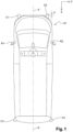
- FIG 1 illustrates a PC carrier vehicle seen from above, for example a series light commercial vehicle of the Citro ⁇ n Jumpy or Ford Expert type or their versions in passenger cars respectively Space Tourer and Traveller.
- the sensors C1 to C4 are located at the four corners of the carrier vehicle VP, the general shape of which, seen from above, can resemble a rectangle.
- the offset d of the front left and right sensors C1 and C2 is only 60 mm in the front zone of the carrier vehicle VP and there is no or almost no lateral overhang of the sensors.
- the sensors C1 to C4 are identical lidars of the aforementioned type LMS-151.
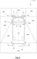
- the sensors C1 to C4 are installed so that their horizontal opening angles cover at least the entire environment close to the carrier vehicle VP with detection zones, some of which may overlap. Such zones are also called “redundancy zones”. These redundancy zones, essential to compensate for failures of one of the sensors C1 to C4, can be double ZR2 (overlapping detection zones scanned by two sensors) or even triple ZR3 (overlapping detection zones scanned by three sensors)
- the present invention considers that redundancy for certain detection zones is not really essential. This is the case in particular for the zones ZR0 corresponding to the left and right sides (or flanks) of the carrier vehicle VP.
- the carrier vehicle VP is programmed to stop.
- simple detection without redundancy (ZRO) is acceptable.
- the left and right front corner sensors C1 and C2 are installed on the carrier vehicle VP being closer to the front face of the vehicle and the center of the carrier vehicle passenger car and with precise orientation determined from their opening angle.
- the orientation of the sensors C1 to C4 is determined in such a way that their detection zones tangent the travel D1 and D2 of the left and right front wheels RA1 and RA2 steered with their maximum steering angle.
- the sensors C1 to C4 have a horizontal opening angle ⁇ of 270° and a vertical opening angle of 1°.
- the front left and right sensors C1 and C2 are fixed at a height from the ground at 23 cm or 30 cm and the rear left and right sensors C3 and C4 at a height of 30 cm.
- Each sensor C1 to C4 is represented by a 270° circle sector with center O1 to 04, symbolizing the horizontal opening angle ⁇ of each sensor C1 to C4.
- the centers O1 to O4 coincide with the "physical" centers of the sensors C1 to C4.
- the centers O1 and O2 of the left and right front sensors C1 and C2 are aligned and tangent to the front face of the carrier vehicle VP which extends along the Y axis, perpendicular to the longitudinal axis XX' of the carrier vehicle VP.
- the opening angles ⁇ of the sensors C1 to C4 define detection zones around the carrier vehicle VP, some of which overlap at least partially once ZR2 or even twice ZR3 thus creating redundancies in the information delivered by the sensors C1 to C4.
- the sensors C1 and C2 participate in the definition of five detection zones around the carrier vehicle VP: two triple redundancy zones ZR3 corresponding respectively to the front left and right zones of the carrier vehicle VP, and a first double redundancy zone ZR2 corresponding to the front zone of the carrier vehicle VP between the two triple redundancy zones ZR3.
- the sensor C1 also participates, with the sensor C3, in the definition of a second zone with double redundancy ZR2 and the sensor C2 also participates, with the sensor C4, in the definition of a third zone with double redundancy ZR2.
- the sensors C3 and C4 respectively define first and second zones without redundancy ZR0 on the left and right sides of the carrier vehicle VP. They also participate in the definition of a fourth zone with double redundancy ZR2 extending to the rear of the carrier vehicle VP.
Landscapes
- Engineering & Computer Science (AREA)
- Physics & Mathematics (AREA)
- Computer Networks & Wireless Communication (AREA)
- General Physics & Mathematics (AREA)
- Radar, Positioning & Navigation (AREA)
- Remote Sensing (AREA)
- Electromagnetism (AREA)
- Optical Radar Systems And Details Thereof (AREA)
- Traffic Control Systems (AREA)
- Control Of Position, Course, Altitude, Or Attitude Of Moving Bodies (AREA)
- Electric Propulsion And Braking For Vehicles (AREA)
Description
- La présente invention concerne de manière générale les capteurs anticollisions et se rapporte plus particulièrement à l'implantation de ces capteurs dans les véhicules dotés d'une fonction de conduite autonome, et en particulier une navette autonome.
- Il est connu d'implanter des capteurs sur un véhicule automobile afin de détecter l'imminence d'une collision avec un véhicule tiers ou une partie d'infrastructure.
- Parmi les capteurs les plus souvent utilisés dans le domaine automobile, on trouve notamment les lidars anticollisions. Ces lidars sont disposés respectivement aux quatre angles du véhicule automobile.
- Le document
WO2017060977 divulgue un dispositif de traitement d'informations comprenant une pluralité d'unités de transmission/réception de lumière et une unité de traitement d'informations. Chacune des unités de transmission/réception de lumière comprend une unité d'émission qui émet une lumière, une unité de balayage qui balaye la lumière émise par l'unité d'émission, et une unité de réception de lumière qui reçoit la lumière réfléchie par un objet - Le document
US 2018059662 divulgue un système de commande pour un véhicule à conduite autonome comprend un dispositif de fourniture d'informations 10 configuré pour fournir à un conducteur des informations et une partie de demande d'opération configurée pour contrôler le dispositif de fourniture d'informations afin de fournir au conducteur des informations pendant la conduite autonome afin de demander ainsi une opération prédéterminée. au conducteur. La partie demande d'opération est dotée d'une partie calcul de temps de marge configurée pour calculer un temps de marge jusqu'à un moment auquel le conducteur doit commencer l'opération lorsque l'opération doit être demandée au conducteur et une partie de contrôle de fourniture d'informations configurée pour fournir au conducteur informations différentes selon le temps de marge. - Le document
EP3081959 divulgue un procédé pour déterminer une position de montage respective d'au moins deux capteurs d'un véhicule automobile autonome. - Le document
US2018136644 divulgue un système, un appareil ou un processus peut être configuré pour mettre en oeuvre une application qui applique des techniques d'intelligence artificielle et/ou d'apprentissage automatique pour prédire un plan d'action optimal (ou un sous-ensemble de plans d'action) pour un système de véhicule autonome (par exemple, un ou plusieurs planificateurs d'un véhicule autonome, un simulateur ou un téléopérateur) à entreprendre en fonction des performances sous-optimales du véhicule autonome et/ou des modifications des données détectées des capteurs (par exemple, nouveaux bâtiments, points de repère, nids-de-poule, etc.). - Le document JO KICHUN ET AL : « Development of Autonomous Car-Part II : A Case Study on the Implementation of an Autonomous Driving System Based on the Distributed Architec » divulgue un procédé de développement d'un véhicule autonome fondé sur un système d'architecture distribué.
- Un lidar, acronyme signifiant « light, ou laser, detecting and ranging », est un système optoélectronique comportant un émetteur de faisceau laser, un récepteur comprenant un collecteur de lumière et un photo détecteur qui transforme la lumière en un signal électrique ainsi qu'une chaine électronique de traitement du signal qui extrait l'information recherchée.
- De tels capteurs utilisent un faisceau laser pour déterminer la distance qui les séparent des objets présents dans l'environnement du véhicule porteur (sous-entendu le véhicule équipé, « porteur » desdits capteurs). Ils permettent de détecter les obstacles dangereux à proximité du véhicule porteur. Ils font partie du début de la chaine de sécurité pour déclencher des freinages d'urgence dans le cas où un obstacle dangereux serait très proche du véhicule porteur.
- Ils sont également utilisés pour permettre des ralentissements plus doux, progressifs, lorsque des obstacles considérés comme dangereux, sont perçus sur la trajectoire du véhicule porteur suffisamment à l'avance.
- Le mode de réalisation décrit dans la présente invention considère plus particulièrement des lidars de type LMS-151 commercialisés par la société Sick, qui sont disposés aux quatre angles du véhicule porteur généralement à 300 mm du sol.
- Ces capteurs permettent de respecter un certain nombre de contraintes, parmi lesquelles :
- l'angle d'ouverture en vertical, considéré centré par rapport au plan médian horizontal du capteur, est de 1° ;
- l'angle d'ouverture en horizontal considéré dans le plan médian du capteur et dont l'origine correspond au centre physique du capteur, est de 270°;
- le plan de détection des capteurs est parallèle à la route ;
- les capteurs sont positionnés à l'extérieur du « gabarit » du véhicule (en dehors de l'encombrement maximum de la caisse du véhicule afin de balayer l'avant du véhicule et ses flancs). Cela implique que le centre « physique » de chaque capteur est dégagé des flancs du véhicule (et idéalement du déport des roues avant lorsqu'elles sont braquées) d'un minimum de 2 cm ; et
- les surfaces de détection (ou zones de détection) se chevauchent pour créer des zones de redondance afin de pallier la défaillance d'un capteur.
- Le respect de ces contraintes impose de disposer les capteurs en dehors du gabarit du véhicule : ils débordent donc de l'encombrement maximum du véhicule. Ils sont dits « en déport » du gabarit du véhicule.
- De tels débordements ou déports, sont potentiellement dangereux et ne sont donc pas acceptables pour un véhicule automobile qui est amené à circuler essentiellement dans un environnement piétonnier comme c'est le cas, notamment, d'une navette autonome amenée à se déplacer au sein d'un site industriel ou d'un espace urbain à forte concentration piétonnière. D'autre part, les capteurs sont naturellement plus exposés à la casse en cas de collision avec des obstacles.
- L'invention a notamment pour but de trouver un compromis dans l'implantation des capteurs sur le véhicule permettant d'assurer à la fois une détection d'obstacle indispensable à la sécurité des piétons et un débordement réduit des capteurs par rapport au gabarit du véhicule pour réduire le risque de casse matérielle.
- A cet effet, elle propose un véhicule automobile équipé d'au moins quatre capteurs anticollisions, identiques, de type lidar, disposés respectivement aux quatre angles du véhicule, chaque capteur possédant un même angle d'ouverture déterminé et définissant au moins une zone de détection autour du véhicule, certaines zones de détection pouvant se chevaucher pour créer de la redondance, caractérisé en ce que les deux capteurs avant gauche et droit sont positionnés et orientés de manière à ce que leurs zones de détection tangentent le déport des roues respectivement avant gauche et droite, en considérant l'angle maximal de braquage des roues avant gauche et droite, et en ce que les deux capteurs arrière gauche et droit définissent des zones de détection, sans chevauchement avec d'autres zones de détection, sur les flancs respectivement gauche et droit du véhicule ; les zones de détection sans chevauchement tangentant le déport des roues avant gauche et droite en considérant leur angle de braquage maximal et dans lequel les capteurs arrière gauche et droit sont positionnés à l'arrière du véhicule de telle manière que leurs centres sont en limite du gabarit du véhicule.
- Selon une caractéristique, les capteurs avant gauche et droit sont positionnés à l'avant du véhicule de telle manière que leurs centres sont en retrait des flancs respectivement gauche et droit du véhicule, vers l'axe longitudinal du véhicule.
- Selon d'autres caractéristiques, le gabarit du véhicule présente, vue de dessus, une forme générale rectangulaire, les capteurs arrière gauche et droit sont positionnés aux angles du rectangle correspondant aux angles arrière gauche et droit du véhicule, et les capteurs avant gauche et droit sont positionné à distance des deux autres angles du rectangle se faisant face.
- Selon encore une autre caractéristique, il n'y a pas de dépassement latéral des capteurs par rapport au gabarit du véhicule considéré avec les rétroviseurs extérieurs gauche et droit déployés.
- Selon une autre caractéristique, le véhicule tel que décrit précédemment, est une navette autonome.
- L'invention sera mieux comprise, et d'autres buts, caractéristiques, détails et avantages de celle-ci apparaîtront plus clairement dans la description explicative qui va suivre faite en référence aux dessins annexés donnés uniquement à titre d'exemple illustrant un mode de réalisation de l'invention et dans lesquels :
- la
figure 1 est une vue de dessus d'un véhicule selon l'invention illustrant l'implantation de quatre capteurs d'angle de type lidar ; et - la
figure 2 est la même vue de dessus que lafigure 1 sur laquelle sont représentées les zones de détection scrutées par les quatre capteurs d'angle. - Sur les figures, les éléments identiques sont repérés par les mêmes signes de référence.
- Le véhicule est représenté dans un repère bidimensionnel XY.
- La
figure 1 illustre un véhicule porteur VP vu de dessus, par exemple un véhicule utilitaire léger série de type Citroën Jumpy ou Peugeot Expert ou leurs versions en véhicules particuliers respectivement Space Tourer et Traveller. - Les capteurs C1 à C4 sont implantés aux quatre angles du véhicule porteur VP, dont la forme générale, vue de dessus peut s'apparenter à un rectangle.
- Dans l'implantation considérée dans la présente invention, le déport d des capteurs avant gauche et droit C1 et C2 est de seulement 60 mm dans la zone avant du véhicule porteur VP et il n'y a pas ou quasiment pas de dépassement latéral des capteurs C1 à C4 par rapport au gabarit du véhicule porteur VP avec les rétroviseurs extérieurs gauche et droit R1 et R2 déployés.
- Les capteurs C1 à C4 sont des lidars identiques du type précité LMS-151.
- En référence à la
figure 2 , les capteurs C1 à C4 sont implantés de manière à ce que leurs angles d'ouverture en horizontal, couvrent au moins tout l'environnement proche du véhicule porteur VP avec des zones de détection dont certaines peuvent se chevaucher. De telles zones sont appelées également « zones de redondance ». Ces zones de redondance, indispensables pour pallier aux défaillances d'un des capteurs C1 à C4, peuvent être double ZR2 (chevauchement de zones de détections scrutées par deux capteurs) voire triple ZR3 (chevauchement de zones de détections scrutées par trois capteurs) - Pour limiter un déport trop important des capteurs C1 à C4 par rapport au gabarit du véhicule porteur VP la présente invention considère qu'une redondance pour certaines zones de détection n'est pas réellement indispensable. C'est le cas notamment pour les zones ZR0 correspondant aux côtés (ou flancs) gauche et droit du véhicule porteur VP.
- En effet, en cas de défaillance d'un capteur C1 à C4, le véhicule porteur VP est programmé pour s'arrêter. Ainsi, sur les côtés ou flancs gauche et droit du véhicule porteur VP, une simple détection sans redondance (ZRO) est acceptable.
- Pour répondre aux contraintes mentionnées ci-dessus avec les conditions sur la redondance considérées dans le cadre de la présente invention, les capteurs des angles avant gauche et droit C1 et C2 sont implantés sur le véhicule porteur VP en étant davantage rapprochés de la face avant du véhicule et du centre du véhicule porteur VP et avec orientation précise déterminée de leur angle d'ouverture.
- L'orientation des capteurs C1 à C4 est déterminée de telle manière que leurs zones de détection tangentent le débattement D1 et D2 des roues avant gauche et droite RA1 et RA2 braquées avec leur angle de braquage maximum.
- Comme indiqué précédemment, les capteurs C1 à C4 présentent un angle d'ouverture en horizontal ⊖ de 270° et un angle d'ouverture en vertical de 1°. Les capteurs avant gauche et droit C1 et C2 sont fixés à une hauteur par rapport au sol à 23 cm ou 30 cm et les capteurs arrière gauche et droit C3 et C4 à une hauteur de 30 cm.
- Chaque capteur C1 à C4 est représenté par un secteur de cercle de 270° de centre O1 à 04, symbolisant l'angle d'ouverture en horizontal Θ de chaque capteur C1 à C4. Les centre O1 à O4 coïncident avec les centres « physique » des capteurs C1 à C4.
- Les centres O1 et O2 des capteurs avant gauche et droit C1 et C2 sont alignés et tangentent la face avant du véhicule porteur VP qui s'étend suivant l'axe Y, perpendiculairement à l'axe longitudinal XX' du véhicule porteur VP.
- Avec une telle implantation des capteurs C1 à C4, les angles d'ouverture Θ des capteurs C1 à C4 définissent des zones de détection autour du véhicule porteur VP dont certaines se chevauchent au moins partiellement une fois ZR2 voire deux fois ZR3 créant ainsi des redondances dans les informations délivrées par les capteurs C1 à C4.
- Les capteurs C1 et C2 participent à la définition de cinq zones de détection autour du véhicule porteur VP : deux zones à triple redondance ZR3 correspondant respectivement aux zones avant gauche et droite du véhicule porteur VP, et une première zone à double redondance ZR2 correspondant à la zone avant du véhicule porteur VP comprise entre les deux zones à triple redondance ZR3.
- Le capteur C1 participe également, avec le capteur C3, à la définition d'une deuxième zone à double redondance ZR2 et le capteur C2 participe également, avec le capteur C4, à la définition d'une troisième zone à double redondance ZR2.
- Les capteurs C3 et C4 définissent respectivement des première et seconde zones sans redondance ZR0 sur les flancs gauche et droit du véhicule porteur VP. Ils participent également à la définition d'une quatrième zone à double redondance ZR2 s'étendant à l'arrière du véhicule porteur VP.
Claims (5)
- Véhicule automobile (VP) équipé d'au moins quatre capteurs anticollisions (C1 à C4), identiques, de type lidar, disposés respectivement aux quatre angles du véhicule (VP), chaque capteur (C1 à C4) possédant un même angle d'ouverture déterminé (Θ) et définissant au moins une zone de détection autour du véhicule (VP), certaines zones de détection pouvant se chevaucher pour créer de la redondance (ZR2, ZR3), caractérisé en ce que les deux capteurs avant gauche et droit (C1 et C2) sont positionnés et orientés de manière à ce que leurs zones de détection tangentent le déport (D1, D2) des roues (RA1, RA2) respectivement avant gauche et droite, en considérant l'angle maximal de braquage des roues avant gauche et droite (RA1, RA2), et en ce que les deux capteurs arrière gauche et droit (C3 et C4) définissent des zones de détection (ZR0), sans chevauchement avec d'autres zones de détection, sur les flancs respectivement gauche et droit du véhicule (VP) ; les zones de détection sans chevauchement (ZRO) tangentant le déport des roues avant gauche et droite (RA1, RA2) en considérant leur angle de braquage maximal, et
dans lequel les capteurs arrière gauche et droit (C3 et C4) sont positionnés à l'arrière du véhicule (VP) de telle manière que leurs centres (O3, O4) sont en limite du gabarit du véhicule (VP). - Véhicule (VP) selon la revendication précédente, caractérisé en ce que les capteurs avant gauche et droit (C1 et C2) sont positionnés à l'avant du véhicule (VP) de telle manière que leurs centres (O1 et O2) sont en retrait des flancs respectivement gauche et droit du véhicule (VP), vers l'axe longitudinal (XX') du véhicule (VP).
- Véhicule (VP) selon la revendication précédente, caractérisé en ce que le gabarit du véhicule (VP) présente, vue de dessus, une forme générale rectangulaire et en ce que les capteurs arrière gauche et droit (C3 et C4) sont positionnés aux angles du rectangle correspondant aux angles arrière gauche et droit du véhicule (VP), et en ce que les capteurs avant gauche et droit (C1 et C2) sont positionné à distance des deux autres angles du rectangle se faisant face.
- Véhicule selon la revendication précédente, caractérisé en ce il n'y a pas de dépassement latéral des capteurs (C1 à C4) par rapport au gabarit du véhicule (VP) considéré avec les rétroviseurs extérieurs gauche et droit (R1 et R2) déployés.
- Véhicule selon l'une des revendications précédente, caractérisé en ce qu'il est une navette autonome.
Applications Claiming Priority (2)
| Application Number | Priority Date | Filing Date | Title |
|---|---|---|---|
| FR1855424A FR3082811B1 (fr) | 2018-06-20 | 2018-06-20 | Vehicule automobile equipe de capteurs anticollisions |
| PCT/FR2019/051458 WO2019243718A1 (fr) | 2018-06-20 | 2019-06-17 | Vehicule automobile equipe de capteurs anticollisions |
Publications (2)
| Publication Number | Publication Date |
|---|---|
| EP3811115A1 EP3811115A1 (fr) | 2021-04-28 |
| EP3811115B1 true EP3811115B1 (fr) | 2023-05-24 |
Family
ID=63557639
Family Applications (1)
| Application Number | Title | Priority Date | Filing Date |
|---|---|---|---|
| EP19742641.4A Active EP3811115B1 (fr) | 2018-06-20 | 2019-06-17 | Vehicule automobile equipe de capteurs anticollisions |
Country Status (5)
| Country | Link |
|---|---|
| US (1) | US11846710B2 (fr) |
| EP (1) | EP3811115B1 (fr) |
| CN (1) | CN112585502B (fr) |
| FR (1) | FR3082811B1 (fr) |
| WO (1) | WO2019243718A1 (fr) |
Families Citing this family (1)
| Publication number | Priority date | Publication date | Assignee | Title |
|---|---|---|---|---|
| US11603110B2 (en) * | 2019-04-18 | 2023-03-14 | Kyndryl, Inc. | Addressing vehicle sensor abnormalities |
Family Cites Families (20)
| Publication number | Priority date | Publication date | Assignee | Title |
|---|---|---|---|---|
| GB2383415B (en) * | 2000-09-08 | 2005-02-23 | Automotive Tech Int | Vehicle wireless sensing and communication system |
| EP2419881B1 (fr) * | 2009-04-15 | 2016-03-30 | Toyota Jidosha Kabushiki Kaisha | Dispositif de détection d'objet |
| DE102009027820A1 (de) * | 2009-07-20 | 2011-01-27 | Robert Bosch Gmbh | Vorrichtung und Verfahren zum unterstützten Einparken eines Fahrzeugs |
| EP2458574B1 (fr) * | 2009-07-22 | 2016-03-30 | Toyota Jidosha Kabushiki Kaisha | Dispositif d aide à la conduite |
| JP5501452B2 (ja) * | 2010-05-19 | 2014-05-21 | 三菱電機株式会社 | 車両後方監視装置 |
| DE102011112812A1 (de) * | 2011-09-07 | 2013-03-07 | GM Global Technology Operations LLC (n. d. Gesetzen des Staates Delaware) | Fahrerunterstützung durch Tot-Winkel-Bereichs Warnung |
| CN102963300B (zh) * | 2012-12-07 | 2015-01-28 | 长安大学 | 防止车辆转弯时与非机动车发生碰撞的提示装置及其方法 |
| US8825303B1 (en) * | 2013-03-28 | 2014-09-02 | Snap-On Incorporated | Wheel alignment apparatus and method for vehicles having electro-mechanical power steering |
| ES2622928T3 (es) * | 2014-02-19 | 2017-07-07 | Kapsch Trafficcom Ag | Dispositivo y procedimiento para la detección de un eje de rueda de un vehículo |
| JP5953385B1 (ja) * | 2015-02-25 | 2016-07-20 | 本田技研工業株式会社 | 車両 |
| US9784829B2 (en) * | 2015-04-06 | 2017-10-10 | GM Global Technology Operations LLC | Wheel detection and its application in object tracking and sensor registration |
| DE102015105720A1 (de) * | 2015-04-15 | 2016-10-20 | Valeo Schalter Und Sensoren Gmbh | Verfahren zum Bestimmen einer jeweiligen Einbauposition von zumindest zwei Sensoren eines Kraftfahrzeugs, Steuereinrichtung, Fahrerassistenzsystem sowie Kraftfahrzeug |
| FR3036181B1 (fr) * | 2015-05-11 | 2019-08-16 | Valeo Schalter Und Sensoren Gmbh | Vehicule automobile equipe de teledetecteurs par laser. |
| US11067689B2 (en) * | 2015-10-06 | 2021-07-20 | Pioneer Corporation | Information processing device, information processing method and program |
| US9632502B1 (en) * | 2015-11-04 | 2017-04-25 | Zoox, Inc. | Machine-learning systems and techniques to optimize teleoperation and/or planner decisions |
| US9734455B2 (en) * | 2015-11-04 | 2017-08-15 | Zoox, Inc. | Automated extraction of semantic information to enhance incremental mapping modifications for robotic vehicles |
| US9507346B1 (en) * | 2015-11-04 | 2016-11-29 | Zoox, Inc. | Teleoperation system and method for trajectory modification of autonomous vehicles |
| EP3254918B1 (fr) * | 2016-06-07 | 2023-05-24 | Volvo Car Corporation | Système de commande adaptative de la vitesse et véhicule comprenant un système de régulateur de vitesse adaptatif |
| DE102016009760A1 (de) * | 2016-08-11 | 2018-02-15 | Trw Automotive Gmbh | Steuerungssystem und Steuerungsverfahren zum Führen eines Kraftfahrzeugs entlang eines Pfades |
| JP6512194B2 (ja) * | 2016-08-26 | 2019-05-15 | トヨタ自動車株式会社 | 自動運転車両の制御システム及び制御方法 |
-
2018
- 2018-06-20 FR FR1855424A patent/FR3082811B1/fr not_active Expired - Fee Related
-
2019
- 2019-06-17 EP EP19742641.4A patent/EP3811115B1/fr active Active
- 2019-06-17 CN CN201980041703.XA patent/CN112585502B/zh active Active
- 2019-06-17 US US16/972,941 patent/US11846710B2/en active Active
- 2019-06-17 WO PCT/FR2019/051458 patent/WO2019243718A1/fr not_active Ceased
Also Published As
| Publication number | Publication date |
|---|---|
| FR3082811B1 (fr) | 2020-07-31 |
| US11846710B2 (en) | 2023-12-19 |
| US20210247518A1 (en) | 2021-08-12 |
| FR3082811A1 (fr) | 2019-12-27 |
| EP3811115A1 (fr) | 2021-04-28 |
| CN112585502B (zh) | 2024-03-22 |
| CN112585502A (zh) | 2021-03-30 |
| WO2019243718A1 (fr) | 2019-12-26 |
Similar Documents
| Publication | Publication Date | Title |
|---|---|---|
| US11367291B2 (en) | Traffic signal display estimation system | |
| KR102714940B1 (ko) | Lidar 시스템 및 방법 | |
| US20200302196A1 (en) | Traffic Signal Analysis System | |
| EP2808700B1 (fr) | Dispositif d'assistance d'entraînement et véhicule l'utilisant | |
| US20170259753A1 (en) | Sidepod stereo camera system for an autonomous vehicle | |
| US20170371336A1 (en) | Driving path determination for autonomous vehicles | |
| CN111186377B (zh) | 红外线相机系统、红外线相机模块以及车辆 | |
| JP2013023182A (ja) | ヘッドランプの配光制御手段 | |
| CN109839636B (zh) | 物体识别装置 | |
| JP2020093737A (ja) | 赤外線カメラシステム及び車両 | |
| JP7649182B2 (ja) | 車両の走行制御装置 | |
| US12594946B2 (en) | Driver assistance apparatus and driver assistance method | |
| US20200094677A1 (en) | Object detection sensor alignment | |
| KR20220029823A (ko) | 자율 주행 시스템 및 자율 주행 방법 | |
| US20230356716A1 (en) | Apparatus and method for controlling the same | |
| US11754905B2 (en) | Phased spatial light modulator for imaging | |
| CN118715457A (zh) | 用于使用光检测和测距扫描仪扫描感兴趣区域的系统和方法 | |
| EP3871138A1 (fr) | Système et procédé pour l'éclairage d'une région latérale d'un véhicule | |
| WO2019243718A1 (fr) | Vehicule automobile equipe de capteurs anticollisions | |
| KR20220148011A (ko) | 차량의 주행을 보조하는 장치 및 그 방법 | |
| JP2025097512A (ja) | 交差道路検出装置、交差道路検出方法及びプログラム | |
| KR20240102060A (ko) | 센서 융합 시스템, 주행 보조 시스템 및 센서 융합 방법 | |
| FR3149578A1 (fr) | Procédé et dispositif d’indication de présence d’objet dans un environnement d’un véhicule | |
| US12429595B2 (en) | Vehicular sensing system and vehicle | |
| KR20240066793A (ko) | 운전자 보조 장치 및 운전자 보조 방법 |
Legal Events
| Date | Code | Title | Description |
|---|---|---|---|
| STAA | Information on the status of an ep patent application or granted ep patent |
Free format text: STATUS: UNKNOWN |
|
| STAA | Information on the status of an ep patent application or granted ep patent |
Free format text: STATUS: THE INTERNATIONAL PUBLICATION HAS BEEN MADE |
|
| PUAI | Public reference made under article 153(3) epc to a published international application that has entered the european phase |
Free format text: ORIGINAL CODE: 0009012 |
|
| STAA | Information on the status of an ep patent application or granted ep patent |
Free format text: STATUS: REQUEST FOR EXAMINATION WAS MADE |
|
| 17P | Request for examination filed |
Effective date: 20201126 |
|
| AK | Designated contracting states |
Kind code of ref document: A1 Designated state(s): AL AT BE BG CH CY CZ DE DK EE ES FI FR GB GR HR HU IE IS IT LI LT LU LV MC MK MT NL NO PL PT RO RS SE SI SK SM TR |
|
| AX | Request for extension of the european patent |
Extension state: BA ME |
|
| DAV | Request for validation of the european patent (deleted) | ||
| DAX | Request for extension of the european patent (deleted) | ||
| GRAP | Despatch of communication of intention to grant a patent |
Free format text: ORIGINAL CODE: EPIDOSNIGR1 |
|
| STAA | Information on the status of an ep patent application or granted ep patent |
Free format text: STATUS: GRANT OF PATENT IS INTENDED |
|
| INTG | Intention to grant announced |
Effective date: 20230109 |
|
| GRAS | Grant fee paid |
Free format text: ORIGINAL CODE: EPIDOSNIGR3 |
|
| GRAA | (expected) grant |
Free format text: ORIGINAL CODE: 0009210 |
|
| STAA | Information on the status of an ep patent application or granted ep patent |
Free format text: STATUS: THE PATENT HAS BEEN GRANTED |
|
| AK | Designated contracting states |
Kind code of ref document: B1 Designated state(s): AL AT BE BG CH CY CZ DE DK EE ES FI FR GB GR HR HU IE IS IT LI LT LU LV MC MK MT NL NO PL PT RO RS SE SI SK SM TR |
|
| REG | Reference to a national code |
Ref country code: GB Ref legal event code: FG4D Free format text: NOT ENGLISH |
|
| REG | Reference to a national code |
Ref country code: CH Ref legal event code: EP |
|
| REG | Reference to a national code |
Ref country code: DE Ref legal event code: R096 Ref document number: 602019029268 Country of ref document: DE |
|
| REG | Reference to a national code |
Ref country code: AT Ref legal event code: REF Ref document number: 1569852 Country of ref document: AT Kind code of ref document: T Effective date: 20230615 |
|
| REG | Reference to a national code |
Ref country code: IE Ref legal event code: FG4D Free format text: LANGUAGE OF EP DOCUMENT: FRENCH |
|
| REG | Reference to a national code |
Ref country code: LT Ref legal event code: MG9D |
|
| REG | Reference to a national code |
Ref country code: NL Ref legal event code: MP Effective date: 20230524 |
|
| REG | Reference to a national code |
Ref country code: AT Ref legal event code: MK05 Ref document number: 1569852 Country of ref document: AT Kind code of ref document: T Effective date: 20230524 |
|
| PG25 | Lapsed in a contracting state [announced via postgrant information from national office to epo] |
Ref country code: SE Free format text: LAPSE BECAUSE OF FAILURE TO SUBMIT A TRANSLATION OF THE DESCRIPTION OR TO PAY THE FEE WITHIN THE PRESCRIBED TIME-LIMIT Effective date: 20230524 Ref country code: PT Free format text: LAPSE BECAUSE OF FAILURE TO SUBMIT A TRANSLATION OF THE DESCRIPTION OR TO PAY THE FEE WITHIN THE PRESCRIBED TIME-LIMIT Effective date: 20230925 Ref country code: NO Free format text: LAPSE BECAUSE OF FAILURE TO SUBMIT A TRANSLATION OF THE DESCRIPTION OR TO PAY THE FEE WITHIN THE PRESCRIBED TIME-LIMIT Effective date: 20230824 Ref country code: NL Free format text: LAPSE BECAUSE OF FAILURE TO SUBMIT A TRANSLATION OF THE DESCRIPTION OR TO PAY THE FEE WITHIN THE PRESCRIBED TIME-LIMIT Effective date: 20230524 Ref country code: ES Free format text: LAPSE BECAUSE OF FAILURE TO SUBMIT A TRANSLATION OF THE DESCRIPTION OR TO PAY THE FEE WITHIN THE PRESCRIBED TIME-LIMIT Effective date: 20230524 Ref country code: AT Free format text: LAPSE BECAUSE OF FAILURE TO SUBMIT A TRANSLATION OF THE DESCRIPTION OR TO PAY THE FEE WITHIN THE PRESCRIBED TIME-LIMIT Effective date: 20230524 |
|
| PG25 | Lapsed in a contracting state [announced via postgrant information from national office to epo] |
Ref country code: RS Free format text: LAPSE BECAUSE OF FAILURE TO SUBMIT A TRANSLATION OF THE DESCRIPTION OR TO PAY THE FEE WITHIN THE PRESCRIBED TIME-LIMIT Effective date: 20230524 Ref country code: PL Free format text: LAPSE BECAUSE OF FAILURE TO SUBMIT A TRANSLATION OF THE DESCRIPTION OR TO PAY THE FEE WITHIN THE PRESCRIBED TIME-LIMIT Effective date: 20230524 Ref country code: LV Free format text: LAPSE BECAUSE OF FAILURE TO SUBMIT A TRANSLATION OF THE DESCRIPTION OR TO PAY THE FEE WITHIN THE PRESCRIBED TIME-LIMIT Effective date: 20230524 Ref country code: LT Free format text: LAPSE BECAUSE OF FAILURE TO SUBMIT A TRANSLATION OF THE DESCRIPTION OR TO PAY THE FEE WITHIN THE PRESCRIBED TIME-LIMIT Effective date: 20230524 Ref country code: IS Free format text: LAPSE BECAUSE OF FAILURE TO SUBMIT A TRANSLATION OF THE DESCRIPTION OR TO PAY THE FEE WITHIN THE PRESCRIBED TIME-LIMIT Effective date: 20230924 Ref country code: HR Free format text: LAPSE BECAUSE OF FAILURE TO SUBMIT A TRANSLATION OF THE DESCRIPTION OR TO PAY THE FEE WITHIN THE PRESCRIBED TIME-LIMIT Effective date: 20230524 Ref country code: GR Free format text: LAPSE BECAUSE OF FAILURE TO SUBMIT A TRANSLATION OF THE DESCRIPTION OR TO PAY THE FEE WITHIN THE PRESCRIBED TIME-LIMIT Effective date: 20230825 |
|
| RAP4 | Party data changed (patent owner data changed or rights of a patent transferred) |
Owner name: EASYMILE Owner name: STELLANTIS AUTO SAS |
|
| PG25 | Lapsed in a contracting state [announced via postgrant information from national office to epo] |
Ref country code: FI Free format text: LAPSE BECAUSE OF FAILURE TO SUBMIT A TRANSLATION OF THE DESCRIPTION OR TO PAY THE FEE WITHIN THE PRESCRIBED TIME-LIMIT Effective date: 20230524 |
|
| PG25 | Lapsed in a contracting state [announced via postgrant information from national office to epo] |
Ref country code: SK Free format text: LAPSE BECAUSE OF FAILURE TO SUBMIT A TRANSLATION OF THE DESCRIPTION OR TO PAY THE FEE WITHIN THE PRESCRIBED TIME-LIMIT Effective date: 20230524 |
|
| PG25 | Lapsed in a contracting state [announced via postgrant information from national office to epo] |
Ref country code: SM Free format text: LAPSE BECAUSE OF FAILURE TO SUBMIT A TRANSLATION OF THE DESCRIPTION OR TO PAY THE FEE WITHIN THE PRESCRIBED TIME-LIMIT Effective date: 20230524 Ref country code: SK Free format text: LAPSE BECAUSE OF FAILURE TO SUBMIT A TRANSLATION OF THE DESCRIPTION OR TO PAY THE FEE WITHIN THE PRESCRIBED TIME-LIMIT Effective date: 20230524 Ref country code: RO Free format text: LAPSE BECAUSE OF FAILURE TO SUBMIT A TRANSLATION OF THE DESCRIPTION OR TO PAY THE FEE WITHIN THE PRESCRIBED TIME-LIMIT Effective date: 20230524 Ref country code: EE Free format text: LAPSE BECAUSE OF FAILURE TO SUBMIT A TRANSLATION OF THE DESCRIPTION OR TO PAY THE FEE WITHIN THE PRESCRIBED TIME-LIMIT Effective date: 20230524 Ref country code: DK Free format text: LAPSE BECAUSE OF FAILURE TO SUBMIT A TRANSLATION OF THE DESCRIPTION OR TO PAY THE FEE WITHIN THE PRESCRIBED TIME-LIMIT Effective date: 20230524 Ref country code: CZ Free format text: LAPSE BECAUSE OF FAILURE TO SUBMIT A TRANSLATION OF THE DESCRIPTION OR TO PAY THE FEE WITHIN THE PRESCRIBED TIME-LIMIT Effective date: 20230524 |
|
| REG | Reference to a national code |
Ref country code: CH Ref legal event code: PL |
|
| REG | Reference to a national code |
Ref country code: BE Ref legal event code: MM Effective date: 20230630 |
|
| REG | Reference to a national code |
Ref country code: DE Ref legal event code: R097 Ref document number: 602019029268 Country of ref document: DE |
|
| PG25 | Lapsed in a contracting state [announced via postgrant information from national office to epo] |
Ref country code: MC Free format text: LAPSE BECAUSE OF FAILURE TO SUBMIT A TRANSLATION OF THE DESCRIPTION OR TO PAY THE FEE WITHIN THE PRESCRIBED TIME-LIMIT Effective date: 20230524 |
|
| PG25 | Lapsed in a contracting state [announced via postgrant information from national office to epo] |
Ref country code: MC Free format text: LAPSE BECAUSE OF FAILURE TO SUBMIT A TRANSLATION OF THE DESCRIPTION OR TO PAY THE FEE WITHIN THE PRESCRIBED TIME-LIMIT Effective date: 20230524 |
|
| PG25 | Lapsed in a contracting state [announced via postgrant information from national office to epo] |
Ref country code: LU Free format text: LAPSE BECAUSE OF NON-PAYMENT OF DUE FEES Effective date: 20230617 |
|
| REG | Reference to a national code |
Ref country code: IE Ref legal event code: MM4A |
|
| PG25 | Lapsed in a contracting state [announced via postgrant information from national office to epo] |
Ref country code: LU Free format text: LAPSE BECAUSE OF NON-PAYMENT OF DUE FEES Effective date: 20230617 |
|
| PLBE | No opposition filed within time limit |
Free format text: ORIGINAL CODE: 0009261 |
|
| STAA | Information on the status of an ep patent application or granted ep patent |
Free format text: STATUS: NO OPPOSITION FILED WITHIN TIME LIMIT |
|
| PG25 | Lapsed in a contracting state [announced via postgrant information from national office to epo] |
Ref country code: IE Free format text: LAPSE BECAUSE OF NON-PAYMENT OF DUE FEES Effective date: 20230617 |
|
| PG25 | Lapsed in a contracting state [announced via postgrant information from national office to epo] |
Ref country code: IE Free format text: LAPSE BECAUSE OF NON-PAYMENT OF DUE FEES Effective date: 20230617 Ref country code: CH Free format text: LAPSE BECAUSE OF NON-PAYMENT OF DUE FEES Effective date: 20230630 |
|
| 26N | No opposition filed |
Effective date: 20240227 |
|
| PG25 | Lapsed in a contracting state [announced via postgrant information from national office to epo] |
Ref country code: SI Free format text: LAPSE BECAUSE OF FAILURE TO SUBMIT A TRANSLATION OF THE DESCRIPTION OR TO PAY THE FEE WITHIN THE PRESCRIBED TIME-LIMIT Effective date: 20230524 |
|
| PG25 | Lapsed in a contracting state [announced via postgrant information from national office to epo] |
Ref country code: SI Free format text: LAPSE BECAUSE OF FAILURE TO SUBMIT A TRANSLATION OF THE DESCRIPTION OR TO PAY THE FEE WITHIN THE PRESCRIBED TIME-LIMIT Effective date: 20230524 Ref country code: IT Free format text: LAPSE BECAUSE OF FAILURE TO SUBMIT A TRANSLATION OF THE DESCRIPTION OR TO PAY THE FEE WITHIN THE PRESCRIBED TIME-LIMIT Effective date: 20230524 Ref country code: BE Free format text: LAPSE BECAUSE OF NON-PAYMENT OF DUE FEES Effective date: 20230630 |
|
| PG25 | Lapsed in a contracting state [announced via postgrant information from national office to epo] |
Ref country code: BG Free format text: LAPSE BECAUSE OF FAILURE TO SUBMIT A TRANSLATION OF THE DESCRIPTION OR TO PAY THE FEE WITHIN THE PRESCRIBED TIME-LIMIT Effective date: 20230524 |
|
| PG25 | Lapsed in a contracting state [announced via postgrant information from national office to epo] |
Ref country code: BG Free format text: LAPSE BECAUSE OF FAILURE TO SUBMIT A TRANSLATION OF THE DESCRIPTION OR TO PAY THE FEE WITHIN THE PRESCRIBED TIME-LIMIT Effective date: 20230524 |
|
| PGFP | Annual fee paid to national office [announced via postgrant information from national office to epo] |
Ref country code: DE Payment date: 20250520 Year of fee payment: 7 |
|
| PGFP | Annual fee paid to national office [announced via postgrant information from national office to epo] |
Ref country code: GB Payment date: 20250520 Year of fee payment: 7 |
|
| PGFP | Annual fee paid to national office [announced via postgrant information from national office to epo] |
Ref country code: FR Payment date: 20250520 Year of fee payment: 7 |
|
| PG25 | Lapsed in a contracting state [announced via postgrant information from national office to epo] |
Ref country code: CY Free format text: LAPSE BECAUSE OF FAILURE TO SUBMIT A TRANSLATION OF THE DESCRIPTION OR TO PAY THE FEE WITHIN THE PRESCRIBED TIME-LIMIT; INVALID AB INITIO Effective date: 20190617 |
|
| PG25 | Lapsed in a contracting state [announced via postgrant information from national office to epo] |
Ref country code: HU Free format text: LAPSE BECAUSE OF FAILURE TO SUBMIT A TRANSLATION OF THE DESCRIPTION OR TO PAY THE FEE WITHIN THE PRESCRIBED TIME-LIMIT; INVALID AB INITIO Effective date: 20190617 |
|
| PG25 | Lapsed in a contracting state [announced via postgrant information from national office to epo] |
Ref country code: TR Free format text: LAPSE BECAUSE OF FAILURE TO SUBMIT A TRANSLATION OF THE DESCRIPTION OR TO PAY THE FEE WITHIN THE PRESCRIBED TIME-LIMIT Effective date: 20230524 |