EP3810893B1 - Laserwerkzeug, das spülmedium und laserstrahl kombiniert - Google Patents
Laserwerkzeug, das spülmedium und laserstrahl kombiniert Download PDFInfo
- Publication number
- EP3810893B1 EP3810893B1 EP18792505.2A EP18792505A EP3810893B1 EP 3810893 B1 EP3810893 B1 EP 3810893B1 EP 18792505 A EP18792505 A EP 18792505A EP 3810893 B1 EP3810893 B1 EP 3810893B1
- Authority
- EP
- European Patent Office
- Prior art keywords
- laser
- laser tool
- tool
- hole
- laser beam
- Prior art date
- Legal status (The legal status is an assumption and is not a legal conclusion. Google has not performed a legal analysis and makes no representation as to the accuracy of the status listed.)
- Active
Links
- 238000010926 purge Methods 0.000 title claims description 50
- 230000015572 biosynthetic process Effects 0.000 claims description 22
- 238000000034 method Methods 0.000 claims description 14
- 230000003287 optical effect Effects 0.000 claims description 14
- 239000007788 liquid Substances 0.000 claims description 9
- 230000008859 change Effects 0.000 claims description 8
- 230000003247 decreasing effect Effects 0.000 claims description 7
- 150000008282 halocarbons Chemical class 0.000 claims description 5
- 238000005755 formation reaction Methods 0.000 description 21
- 239000011435 rock Substances 0.000 description 19
- 239000012530 fluid Substances 0.000 description 18
- 238000003860 storage Methods 0.000 description 12
- 230000007547 defect Effects 0.000 description 11
- 239000000463 material Substances 0.000 description 11
- 238000004519 manufacturing process Methods 0.000 description 10
- 239000007789 gas Substances 0.000 description 9
- VYPSYNLAJGMNEJ-UHFFFAOYSA-N Silicium dioxide Chemical compound O=[Si]=O VYPSYNLAJGMNEJ-UHFFFAOYSA-N 0.000 description 8
- 238000004590 computer program Methods 0.000 description 8
- 239000004576 sand Substances 0.000 description 7
- 230000005540 biological transmission Effects 0.000 description 6
- 238000005553 drilling Methods 0.000 description 6
- 238000012545 processing Methods 0.000 description 6
- 239000007787 solid Substances 0.000 description 6
- 239000004568 cement Substances 0.000 description 5
- 239000006059 cover glass Substances 0.000 description 5
- IJGRMHOSHXDMSA-UHFFFAOYSA-N Atomic nitrogen Chemical compound N#N IJGRMHOSHXDMSA-UHFFFAOYSA-N 0.000 description 4
- VTYYLEPIZMXCLO-UHFFFAOYSA-L Calcium carbonate Chemical compound [Ca+2].[O-]C([O-])=O VTYYLEPIZMXCLO-UHFFFAOYSA-L 0.000 description 4
- 230000009471 action Effects 0.000 description 4
- 238000000859 sublimation Methods 0.000 description 4
- 230000008022 sublimation Effects 0.000 description 4
- 239000000835 fiber Substances 0.000 description 3
- 239000000945 filler Substances 0.000 description 3
- 229930195733 hydrocarbon Natural products 0.000 description 3
- 239000002245 particle Substances 0.000 description 3
- 239000002002 slurry Substances 0.000 description 3
- OKTJSMMVPCPJKN-UHFFFAOYSA-N Carbon Chemical compound [C] OKTJSMMVPCPJKN-UHFFFAOYSA-N 0.000 description 2
- 239000004215 Carbon black (E152) Substances 0.000 description 2
- 229910052769 Ytterbium Inorganic materials 0.000 description 2
- 229910000019 calcium carbonate Inorganic materials 0.000 description 2
- 229910052799 carbon Inorganic materials 0.000 description 2
- 239000000969 carrier Substances 0.000 description 2
- 238000006243 chemical reaction Methods 0.000 description 2
- 238000004891 communication Methods 0.000 description 2
- 238000001816 cooling Methods 0.000 description 2
- 230000007613 environmental effect Effects 0.000 description 2
- 150000002430 hydrocarbons Chemical class 0.000 description 2
- 230000007246 mechanism Effects 0.000 description 2
- 229910052751 metal Inorganic materials 0.000 description 2
- 239000002184 metal Substances 0.000 description 2
- 239000000203 mixture Substances 0.000 description 2
- 229910052757 nitrogen Inorganic materials 0.000 description 2
- 230000008569 process Effects 0.000 description 2
- 230000000246 remedial effect Effects 0.000 description 2
- 239000000126 substance Substances 0.000 description 2
- 230000008685 targeting Effects 0.000 description 2
- NAWDYIZEMPQZHO-UHFFFAOYSA-N ytterbium Chemical compound [Yb] NAWDYIZEMPQZHO-UHFFFAOYSA-N 0.000 description 2
- BVKZGUZCCUSVTD-UHFFFAOYSA-L Carbonate Chemical compound [O-]C([O-])=O BVKZGUZCCUSVTD-UHFFFAOYSA-L 0.000 description 1
- 229910052692 Dysprosium Inorganic materials 0.000 description 1
- 229910052691 Erbium Inorganic materials 0.000 description 1
- 235000019738 Limestone Nutrition 0.000 description 1
- 229910052779 Neodymium Inorganic materials 0.000 description 1
- 229910052777 Praseodymium Inorganic materials 0.000 description 1
- NINIDFKCEFEMDL-UHFFFAOYSA-N Sulfur Chemical compound [S] NINIDFKCEFEMDL-UHFFFAOYSA-N 0.000 description 1
- 229910052775 Thulium Inorganic materials 0.000 description 1
- 238000002679 ablation Methods 0.000 description 1
- QVGXLLKOCUKJST-UHFFFAOYSA-N atomic oxygen Chemical compound [O] QVGXLLKOCUKJST-UHFFFAOYSA-N 0.000 description 1
- KYKAJFCTULSVSH-UHFFFAOYSA-N chloro(fluoro)methane Chemical compound F[C]Cl KYKAJFCTULSVSH-UHFFFAOYSA-N 0.000 description 1
- UUAGAQFQZIEFAH-UHFFFAOYSA-N chlorotrifluoroethylene Chemical compound FC(F)=C(F)Cl UUAGAQFQZIEFAH-UHFFFAOYSA-N 0.000 description 1
- 150000001875 compounds Chemical class 0.000 description 1
- 238000005520 cutting process Methods 0.000 description 1
- 230000002950 deficient Effects 0.000 description 1
- 230000001934 delay Effects 0.000 description 1
- 238000010586 diagram Methods 0.000 description 1
- 238000007599 discharging Methods 0.000 description 1
- KBQHZAAAGSGFKK-UHFFFAOYSA-N dysprosium atom Chemical compound [Dy] KBQHZAAAGSGFKK-UHFFFAOYSA-N 0.000 description 1
- UYAHIZSMUZPPFV-UHFFFAOYSA-N erbium Chemical compound [Er] UYAHIZSMUZPPFV-UHFFFAOYSA-N 0.000 description 1
- 239000007792 gaseous phase Substances 0.000 description 1
- 239000011521 glass Substances 0.000 description 1
- 230000005484 gravity Effects 0.000 description 1
- 229910052736 halogen Inorganic materials 0.000 description 1
- 150000002367 halogens Chemical class 0.000 description 1
- 150000004677 hydrates Chemical class 0.000 description 1
- 125000001183 hydrocarbyl group Chemical group 0.000 description 1
- 229910052739 hydrogen Inorganic materials 0.000 description 1
- 239000001257 hydrogen Substances 0.000 description 1
- 150000002431 hydrogen Chemical class 0.000 description 1
- 239000006028 limestone Substances 0.000 description 1
- 239000007791 liquid phase Substances 0.000 description 1
- 238000012986 modification Methods 0.000 description 1
- 230000004048 modification Effects 0.000 description 1
- 239000012768 molten material Substances 0.000 description 1
- QEFYFXOXNSNQGX-UHFFFAOYSA-N neodymium atom Chemical compound [Nd] QEFYFXOXNSNQGX-UHFFFAOYSA-N 0.000 description 1
- 229910052760 oxygen Inorganic materials 0.000 description 1
- 239000001301 oxygen Substances 0.000 description 1
- 230000035515 penetration Effects 0.000 description 1
- PUDIUYLPXJFUGB-UHFFFAOYSA-N praseodymium atom Chemical compound [Pr] PUDIUYLPXJFUGB-UHFFFAOYSA-N 0.000 description 1
- 239000002244 precipitate Substances 0.000 description 1
- 230000009467 reduction Effects 0.000 description 1
- 230000008439 repair process Effects 0.000 description 1
- 239000004065 semiconductor Substances 0.000 description 1
- 239000007790 solid phase Substances 0.000 description 1
- 239000011593 sulfur Substances 0.000 description 1
- 229910052717 sulfur Inorganic materials 0.000 description 1
- FRNOGLGSGLTDKL-UHFFFAOYSA-N thulium atom Chemical compound [Tm] FRNOGLGSGLTDKL-UHFFFAOYSA-N 0.000 description 1
- 238000012546 transfer Methods 0.000 description 1
- XLYOFNOQVPJJNP-UHFFFAOYSA-N water Substances O XLYOFNOQVPJJNP-UHFFFAOYSA-N 0.000 description 1
- 239000001993 wax Substances 0.000 description 1
- 238000003466 welding Methods 0.000 description 1
Images


Classifications
-
- E—FIXED CONSTRUCTIONS
- E21—EARTH DRILLING; MINING
- E21B—EARTH DRILLING, e.g. DEEP DRILLING; OBTAINING OIL, GAS, WATER, SOLUBLE OR MELTABLE MATERIALS OR A SLURRY OF MINERALS FROM WELLS
- E21B7/00—Special methods or apparatus for drilling
- E21B7/14—Drilling by use of heat, e.g. flame drilling
-
- E—FIXED CONSTRUCTIONS
- E21—EARTH DRILLING; MINING
- E21B—EARTH DRILLING, e.g. DEEP DRILLING; OBTAINING OIL, GAS, WATER, SOLUBLE OR MELTABLE MATERIALS OR A SLURRY OF MINERALS FROM WELLS
- E21B21/00—Methods or apparatus for flushing boreholes, e.g. by use of exhaust air from motor
- E21B21/16—Methods or apparatus for flushing boreholes, e.g. by use of exhaust air from motor using gaseous fluids
-
- E—FIXED CONSTRUCTIONS
- E21—EARTH DRILLING; MINING
- E21B—EARTH DRILLING, e.g. DEEP DRILLING; OBTAINING OIL, GAS, WATER, SOLUBLE OR MELTABLE MATERIALS OR A SLURRY OF MINERALS FROM WELLS
- E21B43/00—Methods or apparatus for obtaining oil, gas, water, soluble or meltable materials or a slurry of minerals from wells
- E21B43/11—Perforators; Permeators
- E21B43/114—Perforators using direct fluid action on the wall to be perforated, e.g. abrasive jets
-
- E—FIXED CONSTRUCTIONS
- E21—EARTH DRILLING; MINING
- E21B—EARTH DRILLING, e.g. DEEP DRILLING; OBTAINING OIL, GAS, WATER, SOLUBLE OR MELTABLE MATERIALS OR A SLURRY OF MINERALS FROM WELLS
- E21B47/00—Survey of boreholes or wells
-
- E—FIXED CONSTRUCTIONS
- E21—EARTH DRILLING; MINING
- E21B—EARTH DRILLING, e.g. DEEP DRILLING; OBTAINING OIL, GAS, WATER, SOLUBLE OR MELTABLE MATERIALS OR A SLURRY OF MINERALS FROM WELLS
- E21B47/00—Survey of boreholes or wells
- E21B47/002—Survey of boreholes or wells by visual inspection
-
- E—FIXED CONSTRUCTIONS
- E21—EARTH DRILLING; MINING
- E21B—EARTH DRILLING, e.g. DEEP DRILLING; OBTAINING OIL, GAS, WATER, SOLUBLE OR MELTABLE MATERIALS OR A SLURRY OF MINERALS FROM WELLS
- E21B7/00—Special methods or apparatus for drilling
- E21B7/14—Drilling by use of heat, e.g. flame drilling
- E21B7/15—Drilling by use of heat, e.g. flame drilling of electrically generated heat
Definitions
- This specification describes examples of laser tools configured to combine a purging medium and a laser beam for output to a target.
- a laser tool may be used to output a laser beam within a wellbore.
- the laser beam may be used in a number of applications, such as creating holes in a wall of the wellbore.
- a laser tool is lowered downhole.
- the laser tool outputs a laser beam targeting the wall of the wellbore. Heat from the laser beam breaks or sublimates rock or other structures to form the hole in the wellbore.
- WO 2016/090229 A1 provides a laser-jet apparatus for creating a penetration through a stress region adjacent to a wellbore includes an outer tool housing, the outer tool housing having a housing central bore.
- a laser assembly includes a lens case with an outer diameter that is smaller than an inner diameter of the housing central bore, defining an annular passage between the outer tool housing and the lens case.
- a focusing lens and a collimating lens are located within the lens case.
- the focusing lens is shaped to control the divergence of a laser beam and the collimating lens is shaped to fix the diameter of the laser beam.
- a jet fluid path is located in the annular passage, the jet fluid path shaped to merge jet fluid with the laser beam.
- the outer tool housing has a frusto-conical tip for directing the combined jet fluid and laser beam to the stress region.
- US 2010/0044102 A1 provides a system, apparatus and methods for removal of material for the path of a laser beam during laser drilling of a borehole and for removal of displaced borehole material from the borehole during laser drilling.
- An example laser tool that operates within a wellbore is configured to combine a purging medium and a laser beam.
- the laser tool includes an integrator configured to receive the laser beam from a laser head and to combine the laser beam and the purging medium.
- a conduit having a shape and length is configured to generate a laminar flow from the purging medium and to produce an output that includes the laminar flow and the laser beam.
- the output is directed by the conduit towards a target within the wellbore.
- At least part of the laser tool is configured for rotation to cause the output to rotate during application of the output to the target.
- the conduit comprises a tubular shape, and the tubular shape of the conduit and the length of the conduit causes the turbulent flow to change to the laminar flow
- the laser tool may include one or more of the following features, either alone or in combination.
- the conduit may be attached to the laser head.
- the laser head may be rotatable to cause the conduit to rotate. Rotation of the conduit may produce a pattern of impact of the laser beam on the target that is a spiral in shape.
- the laser tool may be configured for rotation to produce the pattern of impact by starting at a point and spiraling outward.
- the laser tool may be configured for rotation to produce the pattern of impact by starting at a point and spiraling inward.
- the purging medium may include a gas or a liquid.
- the purging medium may include halocarbon.
- the integrator may be configured to produce a turbulent flow of the purging medium.
- the conduit may be configured to convert the turbulent flow to the laminar flow.
- the laminar flow may surround the laser beam within the conduit.
- the optical power of the laser beam may be within a range of 0.2 kilowatts (kW) to 100 kW.
- the optical power of the laser beam may be below 1.0kW.
- the laser tool may include a connector to connect the laser tool to a coiled tubing string.
- the coiled tubing string may be used for moving the laser tool through the wellbore and within a hole created in a formation through which the wellbore extends.
- a camera may be disposed on the conduit to capture images or video during operation of the laser tool.
- An acoustic sensor may be disposed on the conduit to capture sound during operation of the laser tool.
- An example method for operating a laser tool configured to combine a purging medium and a laser beam.
- the method includes combining the laser beam and the purging medium in a turbulent flow and generating a laminar flow from the turbulent flow.
- the laser beam is contained within the laminar flow.
- the laser tool is rotated while outputting the laser beam and the laminar flow from the laser tool towards a target within a wellbore.
- Generating a laminar flow comprises generating a laminar flow in a conduit, the conduit comprising a tubular shape, and where the tubular shape of the conduit and the length of the conduit cause the turbulent flow to change to the laminar flow.
- the method may include one or more of the following features, either alone or in combination.
- Rotating the laser beam may include initially rotating the laser tool and increasing a diameter of rotation for subsequent rotations of the laser tool until a hole is formed through at least part of the target.
- the laser tool may be moved towards or into the hole.
- the laser tool may be rotated following movement such that the laser beam and the laminar flow from the laser tool are output towards the hole.
- Rotating the laser tool following movement may include initially rotating the laser tool and decreasing a diameter of rotation for subsequent rotations of the laser tool until the hole is extended.
- the laser tool may be moved towards or into the hole.
- the laser tool may be rotated following moving the laser tool towards or into the hole such that the laser beam and the laminar flow from the laser tool are output towards the hole.
- Rotating the laser tool following moving the laser tool into the hole may include initially rotating the laser tool and increasing a diameter of rotation for subsequent rotations of the laser tool until the hole is further extended through the target.
- the laser tool may be moved towards the hole using a coiled tubing string. Rotation of the laser tool may produce a pattern of impact on the target that is a spiral in shape. A combination of the purging medium and rotating the laser tool may cause debris to be expelled from the target away from a path of the laser beam.
- At least part of the systems and processes described in this specification may be controlled by executing, on one or more processing devices, instructions that are stored on one or more non-transitory machine-readable storage media.
- non-transitory machine-readable storage media include but are not limited to read-only memory, an optical disk drive, memory disk drive, and random access memory.
- At least part of the systems and processes described in this specification may be controlled using a computing system comprised of one or more processing devices and memory storing instructions that are executable by the one or more processing devices to perform various control operations.
- An implementation of the laser tool connects to a laser head configured to output a laser beam.
- the laser beam may be provided by a laser generator that is located downhole or at the surface.
- An integrator is configured to combine the laser beam and a purging medium.
- the purging medium may be a liquid or a gas that is output with force from the laser tool in order to disperse debris or other materials cut loose by impact of the laser beam.
- the integrator combines the laser beam and the purging medium in a turbulent flow.
- An example turbulent flow includes a flow pattern having random changes in pressure and flow velocity.
- a conduit - called a laminar flow device - is configured to receive the laser beam and the turbulent flow and to generate a laminar flow based on the turbulent flow.
- An example laminar flow includes a flow that occurs in smooth paths or layers that are relatively consistent in terms of pressure and flow velocity.
- the conduit is configured to pass the combined laser beam and the purging medium in the laminar flow and to output that combination towards a target within the wellbore.
- the combined laser beam and purging medium are coaxial in that the laser beam is contained within the purging medium. In some implementations, the laser beam is surrounded completely by the purging medium within the conduit.
- At least part of the laser tool is configured to rotate and thereby cause its output to rotate during application to a target.
- the entire laser tool may rotate.
- the conduit, the laser head, or both the conduit and the laser head may rotate while the remainder of the laser tool does not rotate.
- the rotation may produce a pattern of impact on the target that is a spiral in shape.
- the diameter of rotation increases for each subsequent rotation of the laser tool until a hole is formed through at least part of the target. Then, after the hole is formed, the laser tool moves towards the hole. Following that movement, the laser tool rotates such that the laser beam and the laminar flow are output towards the hole. At this time, rotating includes decreasing a diameter of rotation for subsequent rotations of the laser tool until the hole is extended further through the target.
- the laser tool is moved further into the hole.
- the laser tool then rotates such that a diameter of rotation for subsequent rotations of the laser tool increases until the hole is further extended through the target. Any or all of the preceding operations may be repeated until a desired depth of the hole is achieved.
- a control system is configured to control movement of at least part of the laser tool to cause the laser beam to move and to rotate within the wellbore.
- the control system may include a computing system and a coiled tubing unit or a wireline.
- the laser tool may be moved downhole via the coiled tubing unit or wireline.
- the movement may be computer-controlled or may be controlled manually. Movement of the laser tool downhole, as described subsequently, may be controlled by sending commands from the computing system to the laser tool.
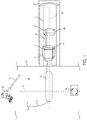
- Fig. 1 shows example components of a laser tool 10.
- Laser tool 10 includes a laser head 11 configured to output a laser beam.
- the laser beam may be generated by a laser generator ("generator"), which is not show in Fig. 1 .
- An example generator is a direct diode laser.
- Direct diode lasers include laser systems that use the output of laser diodes directly in an application. This is in contrast to other types of lasers in which the output of laser diodes is used to pump another laser to generate an output. Examples of direct diode lasers include systems that generate straight-line beam shapes and systems that generate circular beam shapes.
- a straight-line beam shape includes lasers that travel directly from one point to another.
- a straight-line beam shape also includes lasers having a diameter that stays the same or that changes during travel.
- a circular beam shape is generated by rotation of a straight-line beam about an axis to produce a circular pattern at a point where the laser beam impacts its target.
- Example lasers include ytterbium lasers, erbium lasers, neodymium lasers, dysprosium lasers, praseodymium lasers, and thulium lasers.
- the generator may be located at the surface of the well, for example, at the wellhead.
- the laser beam may be transported downhole to the laser tool using an optical transmission medium such as fiber optic cable.
- all or part of the generator may be located within the wellbore.
- the optical power of the laser beam is above 1.0 kilowatts (kW)
- the laser beam has an optical power that is within a range of 0.2kW to 100 kW. In some implementations, the laser beam has an optical power of 1kW or less and has an intensity of 5kW/cm 2 (kilowatts per centimeter squared) or greater. In some implementations, the laser beam has a diameter that is within a range of 0.25 inches (6.35 millimeters (mm)) to 2.0 inches (50.8mm).
- laser tool 10 includes an input mount 12 for the laser head.
- the input mount 12 receives and holds the laser head.
- Cover glass 13 may include a lens or glass that passes the laser beam from the laser head to integrator 14.
- the cover glass may not change the size or the shape of the laser beam.
- the cover glass may change the size or the shape of the laser beam.
- the cover glass may collimate the laser beam. Collimation includes causing the laser beam to maintain a substantially constant cross-sectional area.
- collimation may include reducing the cross-sectional area of the laser beam.
- the cover glass may focus or disperse the laser beam. In any case, the resulting laser beam should have a sufficient size and shape to fit within conduit 20, namely the laminar flow device.
- Integrator 14 is configured - for example, structured - to receive the laser beam and to combine the received laser beam with one or more purging media.
- the purging media may be or include gas, liquid, or both gas and liquid.
- the purging media may be or include different types of gas, different types of liquid, or different types of gas and liquid.
- the choice of purging media to use, such as gas or liquid can be based on the composition of the target, such as rock in a formation, and the pressure of a reservoir associated with the formation.
- the purging media can be or include a non-reactive, non-damaging gas such as nitrogen or a liquid such as halocarbon.
- a halocarbon includes a compound, such as a chlorofluorocarbon, that incudes carbon combined with one or more halogens.
- halocarbon include halocarbon-oil having viscosities in a range from halocarbon-oil 0.8 centipoise (cP) to halocarbon-oil 1000 cP at 100 degrees (°) Fahrenheit (37.8° Celsius).
- a gas purging medium may be appropriate when pressure in the wellbore is small, for example, less than 50000 kilopascals, less than 25000 kilopascals, less than 10000 kilopascals, less than 5000 kilopascals, less than 2500 kilopascals, less than 1000 kilopascals, or less than 500 kilopascals.
- a purging medium is provided to integrator 14 via purge inputs 15 and 16.
- Integrator 14 includes a cavity 18 to receive the purging media from the inputs. Within this cavity, the purging medium is a turbulent flow.
- the integrator combines the laser beam from the laser head with the purging medium in the turbulent flow to produce an output. The integrator outputs the combined the laser beam and purging medium in the turbulent flow to conduit 20.
- Conduit 20 is configured to receive the combined laser beam and purging medium in the turbulent flow.
- the tubular shape of the conduit and the length of the conduit causes the turbulent flow to change to the laminar flow. Different lengths may be required to convert turbulent flows having different pressures to laminar flows. For example, for a flow having a greater pressure, a longer conduit may be required to convert the flow from a turbulent flow to a laminar flow.
- conduit 20 is within a range of 0.25 inches (6.35mm) to 2.0 inches (50.8mm) in diameter and 6 inches (15.24 centimeters (cm)) to 40 inches (100 cm) in length.
- conduit 20 converts a turbulent flow 21 entering at inlet 22 into a laminar flow 24 at its output 25.
- the turbulent and laminar flows are depicted conceptually using arrows.
- the laminar flow is coaxial with the laser beam in the sense that the laser beam is embedded in and output with the purging medium.
- the purging medium may completely surround the laser beam during passage of both through conduit 20.
- the laminar flow is constant over time. In some implementations, the laminar flow varies over time.
- At least part of the laser tool is configured to rotate within the wellbore in order to cause the conduit to rotate.
- the laser beam and the purging medium in the laminar flow also rotate within the wellbore.
- rotation is about an axis that intersects a hole to be formed by the laser tool.
- laser tool 10 is inside wellbore 28 and is controlled to form a hole 30 within wall 32 of the wellbore 28.
- wellbore 28 passes through a hydrocarbon-bearing rock formation 33 that may include various materials, such as limestone, shale, or sandstone.
- the hole to be formed is intersected by axis 34.
- Laser tool 10 is configured to rotate so that conduit 20 rotates around this axis.
- An example rotation is depicted by arrows 27.
- conduit 20 may be mounted to a rotational device 35 mounted to the laser head.
- the rotational device may rotate to cause conduit 20 to rotate about axis 34 in order to create the hole, as described subsequently.
- the entire laser tool may rotate within the wellbore to cause the conduit to rotate about the axis.
- the coiled tubing unit may be controlled to rotate the laser tool about the axis.
- coiled tubing sting 37 may be controlled to implement the rotation.
- the laser head may rotate within the wellbore to cause the conduit to rotate about the axis.
- the control system is configured to control movement, including rotation, of the laser tool within the wellbore.
- the control system can include, for example, a hydraulic system, an electrical system, or a motor-operated system to move the laser tool.
- a motor or other mechanical mechanism may be operated to rotate the entire laser tool or the laser head only as described in the preceding paragraph.
- the motor or other mechanical mechanism may be controlled by the computing system to initiate, to continue, and to end the rotation.
- the laser tool may be moved uphole and downhole by the coiled tubing unit or a wireline.
- a reel that is part of the coiled tubing unit assembly may move the laser tool along longitudinal axis 39 of the wellbore - vertically in the case of a vertical well.
- the laser tool may be suspended within the wellbore through connection to a bottom hole assembly. Lateral movement of the laser tool within the wellbore may be implemented via the coiled tubing string.
- a connector (not shown) may connect the laser tool, the laser head, or both to the coiled tubing string.
- the lateral movement includes, for example, movement into and out of holes formed by the laser tool, as described with respect to Figs. 4, 5, and 6 .
- the coiled tubing unit may also be controlled to rotate the laser tool within the wellbore.
- the rotation may be around longitudinal axis 39 of wellbore 28.
- An example rotation is depicted by arrows 40.
- the rotation may be used to position the laser tool so that the output of the laser tool is directed towards its target. This rotation may be implemented by rotating the coiled tubing string.
- Laser tool 10 also includes cabling 42 that runs uphole to the surface of the wellbore.
- the cabling may include power cables to run electrical power to the laser tool.
- the electrical power may be generated uphole in some implementations.
- the cabling may include communication cables such as Ethernet or fiber optics to carry commands to the laser tool.
- the commands may be generated by a computing system 44 that is located at the surface.
- the commands may control operation of the laser tool.
- the commands may include commands to turn the laser generator on or off, to adjust an intensity of the laser beam, or to control movement, including rotation, of the laser beam within the wellbore. In some implementations, all or some of these commands may be conveyed wirelessly.
- Dashed arrow 45 represents communications between the laser tool and the computing system. Casing may protect all or part of the cabling from downhole conditions.
- the computing system may be part of the control system for the laser tool.
- the computing system may be configured - for example, programmed - to control positioning, operation, and rotation of the laser tool. Examples of computing systems that may be used are described in this specification. Signals may be exchanged between the computing system and the control system via wired or wireless connections.
- the control system may include on-board circuitry or an on-board computing system to implement control over the positioning and operation of the laser tool.
- the on-board circuitry or on-board computing system are "on-board" in the sense that they are located on the laser tool itself or downhole with the laser tool, rather than at the surface.
- the on-board computing system may communicate with the computing system on the surface to control operation and movement of the laser tool.
- the example laser tool may also include one or more sensors 48 to monitor environmental conditions in the wellbore and to output signals indicative of the environmental conditions.
- the sensors may include temperature sensors to measure temperature downhole, pressure sensors to measure pressure downhole, and vibration sensors to measure vibrations levels downhole.
- the computing system may receive signals from one or more of these sensors. The signals received from the sensors may indicate that there are problems inside the wellbore or that there are problems with the laser tool. A drilling engineer may take corrective action based on these signals. For example, if a temperature or pressure downhole is such that equipment such as the laser tool may be damaged, that equipment may be withdrawn from the wellbore. Other sensors may also be included in the laser tool.
- the laser tool may include acoustic sensors for obtaining acoustic data, a camera for capturing images or video, or an acoustic camera configured both to obtain acoustic data and to capture images or video.
- the acoustic sensors may be located at or near the output of conduit 20.
- the camera may be located on or near the laser head or at or near the output of the conduit 20.
- the acoustic camera may be located on or near the laser head or at or near the output of the conduit 20.
- Transmission media such as fiber optics or Ethernet may run the length of conduit 20 and connect to cabling that leads to the surface. The transmission media may be located on the exterior of conduit 20 or on the interior or conduit 20.
- Data obtained from the acoustic sensors, the camera, or the acoustic camera may be sent to the surface computing system via the transmission media and the cabling.
- the data may be processed to view the operations down-hole in real-time.
- real-time may not mean that two actions are simultaneous, but rather may include actions that occur on a continuous basis or track each other in time, taking into account delays associated with processing, data transmission, and hardware.
- the data may be processed to determine downhole conditions. For example, if an image of a hole being drilled shows that the hole is not within a target location, the computing system may control the laser tool to change the location of the hole. For example, if the acoustic data indicates the presence of excess debris or unexpected rock in the formation, operation of the laser tool may be changed to account for these conditions.
- data obtained from the acoustic sensors, the camera, or the acoustic camera may be sent via the transmission media to a computing system that is on-board the laser tool.
- the on-board computing system may perform all or some of the operations described in the preceding paragraph.
- the on-board computing system may cooperate with a surface-based computing system to control operation of the laser tool based on sensor readings.
- the on-board computing system may be configured - for example, programmed - to control operation when the sensor readings are within a prescribed range. That is, automatic controls may be implemented, rather than requiring input from a drilling engineer. If the sensor readings are outside the prescribed range, the surface-based computing system may take over control of the laser tool.
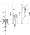
- Figs. 4, 5, and 6 show an example operation of a laser tool 50, which may be the same as, or have the same features as, laser tool 10 of Fig. 1 .
- laser tool 50 is controlled to drill a lateral hole in a wall 51 of wellbore 53.
- all or part of the laser tool is rotated while outputting a laser beam 54 and the laminar flow towards the wall of the wellbore - the target in this example.
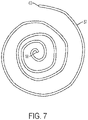
- Rotation is depicted conceptually by circles 55 in each figure. The rotation produces a pattern of impact on the wall that is a spiral in shape.
- An example pattern of impact 57 that is spiral is shown in Fig. 7 .
- the pattern of impact may be formed by rotating the laser tool at an increasing diameter, as shown in Figs. 4 and 6 .
- an increasing diameter includes the spiral starting from point 58 in Fig. 7 and spiraling outward to point 63.
- the pattern of impact may be formed by rotating the laser tool at a decreasing diameter, as shown in Fig. 5 .
- a decreasing diameter includes the spiral starting from point 63 and spiraling inward to point 58.
- Other patterns of rotation may be used.
- a pattern may include concentric circles.
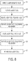
- the laser tool operates by combining a laser beam and a purging medium in a turbulent flow, generating a laminar flow from the turbulent flow, and rotating the laser tool while outputting the laser beam and the laminar flow from the laser tool towards a target within a wellbore.
- the target is an unpenetrated rock formation wall within the wellbore.
- the laser beam may initially be directed (81) to or near a center of the hole to be formed.
- the laser beam removes material - for example, through sublimation, spallation, or both - from the wall of the wellbore to form the hole.
- Sublimation includes changing from a solid phase directly into a gaseous phase without first changing into a liquid phase.
- laser tool 50 is positioned to form a hole centered at point 56 in the wall of the wellbore.
- the control system may cause the coiled tubing unit to move the laser tool to a location near to where the hole is to be formed.
- the laser tool may be moved so that conduit 58 aligns to the center of the hole.
- conduit 58 is rotated relative to the wall of wellbore 53 while the laser tool outputs the laser beam and the laminar flow. Rotation is depicted conceptually in Figs. 4, 5, and 6 by arrows 59.
- the laser beam forms the hole through spallation, sublimation, or a combination of spallation and sublimation.
- the laser tool rotates (82) so that its output, namely the laser beam and the laminar flow, is provided in an expanding spiral pattern.
- diameters for subsequent rotations of the laser tool increase until an initial part of a hole is formed in the wall of the wellbore. This is depicted conceptually by circles 55 becoming larger from left to right.
- the entire laser tool may be rotated or only part of the laser tool, such as the laser head and conduit, may rotated during operation.
- rotation is about an axis 60 that intersects the center of the hole or near the center of the hole to be formed by the laser tool.
- the laser tool is moved (83) towards the hole or into the hole in some cases. Movement may be lateral along axis 60, as shown in Figs. 4 and 5 . In some cases, this movement is implemented using the coiled tubing unit or a wireline and may be controlled manually, by a computing system at the surface or by an on-board computing system.
- the laser tool is again rotated (84) following this movement such that the laser beam and the laminar flow from the laser tool are output to extend the hole.
- the initial rotation of the laser tool starts at the outside edge of a spiral pattern (where the prior rotation of Fig. 4 ended) and spirals inward towards or to the center of the hole, as shown in Fig.
- the laser tool is moved (85) towards the hole or into the hole as in this example. Movement may be along axis 60, as shown in Fig. 6 . In some cases, this movement is implemented using the coiled tubing unit or a wireline and may be controlled manually, by a computing system at the surface, or by an on-board computing system.
- the laser tool is again rotated (86) following this movement such that the laser beam and the laminar flow from the laser tool are output towards the hole. In this example, the rotation of the laser tool starts at the center of a spiral pattern such as the center of the hole (where the prior rotation of Fig. 5 ended) and spirals outward towards or to the edge of the hole.
- the diameter of rotation is increased for subsequent rotations of the laser tool until the hole is extended through the wall of the wellbore.
- This is depicted conceptually in Fig. 6 by circles 55 becoming larger from left to right.
- Rotation of the laser tool or components of the laser tool may be implemented as described previously.
- the combination of the spiral rotation and the laminar flow of the purging media causes debris broken-off from the wellbore wall to be expelled from the hole out of the path of the laser beam. Purging media from the laminar flow may carry debris into the wellbore and to the surface in the examples of Figs. 4, 5, and 6 .
- Figs. 4, 5, and 6 need not occur in the sequence shown. For example, hole formation may start with a decreasing spiral pattern, followed by an increasing spiral pattern, and so forth. In some cases, a hole may be formed using a single rotational sequence without lateral movement towards or into the hole.
- the laser tool may be moved into the hole later than shown in Figs. 4 to 6 - for example, in a fourth movement (not shown). In some operations, the laser tool may be moved into the hole sooner than shown in Figs. 4 to 6 - for example, in the second movement.
- the amount of movement of the laser tool towards or into the hole may depend on various factors, such as the depth of the hole to be drilled, the hardness of the target, and the intensity of the laser beam used.
- the speed of rotation, optical power of the laser beam, duration of use, distance from the purging output to the target, and the purging flow rate and type may be determined based on a composition of the rock or other target to be ablated by the laser beam. For example, if a rock sample has more than 55% quartz (SiO 2 ), then spallation can occur by breaking cementation and discharging resulting grains. This may occur using laser beams having an optical power within a range of 800 Watts (W) to 1200W. By contrast, a carbonate formation may require greater optical power, such as 5000W, to dissociate the calcium carbonate and cause spallation.
- the laser tool is mounted on a ytterbium laser head to form a hole through sandstone.
- the energy delivered to the sandstone is 1200W and the laser beam is a collimated beam having a 0.25 inch (6.35mm) diameter.
- air is used as the purging medium.
- the laser tool is moved in a spiral pattern to form a circular shape hole.
- the purging medium expels debris and cuttings as described previously to create a circular hole through the sandstone.
- the example laser tool described in this specification may be operated in wells that are vertical or in wells that are, in whole or part, non-vertical.
- the laser tools may be operated in a vertical well, a deviated well, a horizontal well, or a partially horizontal well, where horizontal is measured relative to the Earth's surface.
- the example laser tool may operate downhole to stimulate a wellbore.
- the laser tool may operate downhole to create a fluid flow path through a rock formation.
- the fluid flow path may be created by controlling the laser tool to direct a laser beam towards the rock formation.
- the laser beam has an energy density that is great enough to cause at least some of the rock in the rock formation to sublimate or to break to form a hole.
- Fluids, such as water may be introduced into the hole to fracture the rock formation and thereby promote the flow of production fluid, such as oil, from the rock formation into the wellbore.
- the example laser tool may operate downhole to create holes in a casing in the wellbore to repair cementing defects.
- a wellbore includes a casing that is cemented in place to reinforce the wellbore against a rock formation.
- cement slurry is injected between the casing and the rock formation. Defects may occur in the cement layer, which may require remedial cementing. Remedial cementing may involve squeezing additional cement slurry into the space between the casing and the rock formation.
- the example laser tool may be used to direct a laser beam to the casing to create one or more holes in the casing on or near a cementing defect. The holes may provide access for a cementing tool to squeeze cement slurry through the hole into the defect.
- the example laser tool may operate downhole to create holes in a casing in the wellbore to provide access for a wellbore drilling tool.
- an existing single wellbore is converted to a multilateral well.
- a multilateral well is a single well having one or more wellbore branches extending from a main borehole.
- a hole is created in the casing of the existing wellbore.
- the example laser tool may be used to create a hole in the casing at a desired location for a wellbore branching point. The hole may provide access for drilling equipment to drill the lateral wellbore.
- the example laser tool may operate downhole to create holes in a casing in the wellbore to provide sand control.
- sand or other particles may enter the wellbore causing a reduction in production rates or damage to downhole equipment.
- the example laser tool may be used to create a sand screen in the casing.
- the laser tool may be used to perforate a casing by creating a number of holes in the casing that are small enough to prevent or to reduce entry of sand or other particles into the wellbore while maintaining flow of production fluid into the wellbore.
- the example laser tool may operate downhole to re-open a blocked fluid flow path.
- production fluid flows from tunnels or cracks in the rock formation into the wellbore through holes in the wellbore casing and cement layer. These production fluid flow paths may become clogged with debris contained in the production fluid.
- the example laser tool may be used to generate a laser beam that has an energy density that is great enough to liquefy or to sublimate the debris in the flow paths, allowing for removal of the debris together with production fluid.
- a laser tool may be used to liquefy or to sublimate sand or other particles that may have become packed tightly around a sand screen in the casing, thereby re-opening a production fluid flow path into the wellbore.
- the example laser tool may operate downhole to weld a wellbore casing or other component of a wellbore.
- one or more metal components of a wellbore may become rusted, scaled, corroded, eroded, or otherwise defective. Such defects may be repaired using welding techniques.
- the laser tools may be used to generate a laser beam that has an energy density that is great enough to liquefy metal or other material to create a weld.
- material of a wellbore component such as a casing material, may be melted using the laser tool. Resulting molten material may flow over or into a defect, for example due to gravity, thus covering or repairing the defect upon cooling and hardening.
- the laser tool may be used in combination with a tool that provides filler material to the defect.
- the laser tool may be used to melt an amount of filler material positioned on or near a defect.
- the molten filler material may flow over or into a defect, thus covering or repairing the defect upon cooling and hardening.
- the example laser tool may operate downhole to heat solid or semi-solid deposits in a wellbore.
- solid or semi-solid substances may deposit on wellbore walls or on downhole equipment causing reduced flow or blockages in the wellbore or production equipment.
- Deposits may be or include condensates (solidified hydrocarbons), asphaltene (a solid or semi-solid substance comprised primarily of carbon, hydrogen, nitrogen, oxygen, and sulfur), tar, hydrates (hydrocarbon molecules trapped in ice), waxes, scale (precipitate caused by chemical reactions, for example calcium carbonate scale), or sand.
- the example laser tool may be used to generate a laser beam that has an energy density that is great enough to melt or to reduce the viscosity of deposits.
- the liquefied deposits can be removed together with production fluid or other fluid present in the wellbore.
- At least part of the example laser tool and its various modifications may be controlled by a computer program product, such as a computer program tangibly embodied in one or more information formation carriers.
- Information carriers include one or more tangible machine-readable storage media.
- the computer program product may be executed by a data processing apparatus.
- a data processing apparatus can be a programmable processor, a computer, or multiple computers.
- a computer program may be written in any form of programming language, including compiled or interpreted languages. It may be deployed in any form, including as a stand-alone program or as a module, component, subroutine, or other unit suitable for use in a computing environment. A computer program may be deployed to be executed on one computer or on multiple computers. The one computer or multiple computers can be at one site or distributed across multiple sites and interconnected by a network.
- Actions associated with implementing the systems may be performed by one or more programmable processors executing one or more computer programs. All or part of the systems may be implemented as special purpose logic circuitry, for example, an field programmable gate array (FPGA) or an ASIC application-specific integrated circuit (ASIC), or both.
- FPGA field programmable gate array
- ASIC application-specific integrated circuit
- processors suitable for the execution of a computer program include, by way of example, both general and special purpose microprocessors, and any one or more processors of any kind of digital computer.
- a processor will receive instructions and data from a read-only storage area or a random access storage area or both.
- Elements of a computer include one or more processors for executing instructions and one or more storage area devices for storing instructions and data.
- a computer will also include, or be operatively coupled to receive data from, or transfer data to, or both, one or more machine-readable storage media, such as mass storage devices for storing data, such as magnetic, magneto-optical disks, or optical disks.
- Non-transitory machine-readable storage media suitable for embodying computer program instructions and data include all forms of non-volatile storage area, including by way of example, semiconductor storage area devices, such as EPROM (erasable programmable read-only memory), EEPROM (electrically erasable programmable read-only memory), and flash storage area devices; magnetic disks, such as internal hard disks or removable disks; magneto-optical disks; and CD-ROM (compact disc read-only memory) and DVD-ROM (digital versatile disc read-only memory).
- semiconductor storage area devices such as EPROM (erasable programmable read-only memory), EEPROM (electrically erasable programmable read-only memory), and flash storage area devices
- magnetic disks such as internal hard disks or removable disks
- magneto-optical disks magneto-optical disks
- CD-ROM compact disc read-only memory
- DVD-ROM digital versatile disc read-only memory
Claims (15)
- Laserwerkzeug (10), das zum Betrieb innerhalb eines Bohrlochs (28) ausgestaltet ist, wobei das Laserwerkzeug umfasst:einen Integrator (14), der ausgestaltet ist, um einen Laserstrahl von einem Laserkopf (11) zu empfangen und den Laserstrahl und ein Spülmedium zu kombinieren; undeine Rohrleitung (20) mit einer Form und Länge, um aus dem Spülmedium eine laminare Strömung zu erzeugen und eine Ausgabe zu produzieren, die aus der laminaren Strömung und dem Laserstrahl zusammengesetzt ist, wobei die Ausgabe in Richtung eines Ziels innerhalb des Bohrlochs (28) gelenkt wird;wobei mindestens ein Teil des Laserwerkzeugs (10) zur Rotation ausgestaltet ist, um zu bewirken, dass die Ausgabe während der Applikation auf das Ziel rotiert, undwobei die Rohrleitung (20) eine Röhrenform umfasst, wobei die Röhrenform der Rohrleitung und die Länge der Rohrleitung bewirken, dass sich die turbulente Strömung zu der laminaren Strömung ändert.
- Laserwerkzeug (10) nach Anspruch 1, wobei die Rohrleitung an dem Laserkopf befestigt ist, und wobei der Laserkopf rotierbar ist, um zu bewirken, dass die Rohrleitung rotiert.
- Laserwerkzeug (10) nach Anspruch 2, wobei Rotation der Rohrleitung ein Einflussmuster auf dem Ziel produziert, das spiralförmig ist, und wobei das Laserwerkzeug (10) gegebenenfalls zur Rotation ausgestaltet ist, um das Einflussmuster (57) zu produzieren, indem an einem Punkt (58) begonnen und spiralförmig auswärts gegangen wird, oder wobei das Laserwerkzeug (10) zur Rotation ausgestaltet ist, um das Einflussmuster (57) zu produzieren, indem an einem Punkt (63) begonnen und spiralförmig einwärts gegangen wird.
- Laserwerkzeug (10) nach Anspruch 1, wobei das Spülmedium Halogenkohlenstoff und/oder Flüssigkeit und/oder Gas umfasst.
- Laserwerkzeug (10) nach Anspruch 1, wobei der Integrator (14) ausgestaltet ist, um eine turbulente Strömung des Spülmediums zu produzieren; und
wobei die laminare Strömung den Laserstrahl umgibt. - Laserwerkzeug (10) nach Anspruch 1, wobei eine optische Leistung des Laserstrahls innerhalb eines Bereichs von 0,2 Kilowatt (kW) bis 100 kW liegt, oder wobei eine optische Leistung des Laserstrahls unter 1,0 Kilowatt (kW) liegt.
- Laserwerkzeug (10) nach Anspruch 1, des Weiteren umfassend:
einen Verbinder, um das Laserwerkzeug (10) mit einem Wickelrohr- (Coiled Tubing)-Strang zu verbinden, wo der Coiled Tubing-Strang (37) zum Bewegen des Laserwerkzeugs (10) durch das Bohrloch und innerhalb eines Lochs dient, das in einer Formation erstellt wurde, durch die sich das Bohrloch (28) erstreckt. - Laserwerkzeug (10) nach Anspruch 1, des Weiteren umfassend:
eine Kamera auf der Rohrleitung, um während des Betriebs des Laserwerkzeugs (10) Bilder oder Video zu erfassen, und/oder einen akustischen Sensor auf der Rohrleitung, um während des Betriebs des Laserwerkzeugs (10) Schall zu erfassen. - Verfahren zum Betreiben eines Laserwerkzeugs (10), umfassend:Kombinieren eines Laserstrahls und eines Spülmediums in einer turbulenten Strömung;Erzeugen einer laminaren Strömung aus der turbulenten Strömung, wobei der Laserstrahl innerhalb der laminaren Strömung enthalten ist; undRotieren des Laserwerkzeugs (10), während der Laserstrahl und die laminare Strömung aus dem Laserwerkzeug in Richtung eines Ziels innerhalb eines Bohrlochs (28) ausgegeben werden,wobei Erzeugen einer laminaren Strömung Erzeugen einer laminaren Strömung in einer Rohrleitung (20) umfasst, wobei die Rohrleitung (20) eine Röhrenform umfasst,wobei die Röhrenform der Rohrleitung (20) und die Länge der Rohrleitung (20) bewirken, dass die turbulente Strömung sich zu der laminaren Strömung ändert.
- Verfahren nach Anspruch 9, wobei Rotieren des Laserstrahls umfasst:
anfängliches Rotieren des Laserwerkzeugs (10); und Erhöhen eines Rotationsdurchmessers für nachfolgende Rotationen des Laserwerkzeugs (10), bis durch mindestens einen Teil des Ziels hindurch ein Loch gebildet worden ist. - Verfahren nach Anspruch 10, des Weiteren umfassend:nachdem das Loch gebildet worden ist, Bewegen des Laserwerkzeugs (10) in Richtung des Lochs oder in dieses hinein; undRotieren des Laserwerkzeugs (10) nach dem Bewegen, so dass der Laserstrahl und die laminare Strömung aus dem Laserwerkzeug (10) in Richtung des Lochs ausgegeben werden, wobei Rotieren des Laserwerkzeugs (10) nach dem Bewegen umfasst:anfängliches Rotieren des Laserwerkzeugs (10); undVerringern eines Rotationsdurchmessers für nachfolgende Rotationen des Laserwerkzeugs (10), bis das Loch durch mindestens einen Teil des Ziels hindurch erweitert worden ist.
- Verfahren nach Anspruch 10, ferner umfassend:nachdem das Loch erweitert worden ist, Bewegen des Laserwerkzeugs (10) in Richtung des Lochs oder in dieses hinein; undRotieren des Laserwerkzeugs (10) nach Bewegen des Laserwerkzeugs in Richtung des Lochs oder in dieses hinein, so dass der Laserstrahl und die laminare Strömung aus dem Laserwerkzeug in Richtung des Lochs ausgegeben werden, wobei Rotieren des Laserwerkzeugs (10) nach dem Bewegen des Laserwerkzeugs (10) in das Loch umfasst:anfängliches Rotieren des Laserwerkzeugs (10); undErhöhen eines Rotationsdurchmessers für nachfolgende Rotationen des Laserwerkzeugs (10), bis das Loch durch mindestens einen Teil des Ziels hindurch neuerlich erweitert worden ist.
- Verfahren nach Anspruch 11, wobei Bewegen des Laserwerkzeugs (10) in Richtung des Lochs oder in dieses hinein unter Verwendung eines Coiled Tubing-Strangs (37) durchgeführt wird.
- Verfahren nach Anspruch 9, wobei Rotation des Laserwerkzeugs (10) ein Einflussmuster (57) auf dem Ziel produziert, welches spiralförmig ist.
- Verfahren nach Anspruch 9, wobei eine Kombination aus dem Spülmedium und Rotieren des Laserwerkzeugs (10) bewirkt, dass Trümmerteile aus dem Ziel von einem Pfad des Laserstrahls vertrieben werden.
Applications Claiming Priority (2)
| Application Number | Priority Date | Filing Date | Title |
|---|---|---|---|
| US16/056,701 US10822879B2 (en) | 2018-08-07 | 2018-08-07 | Laser tool that combines purging medium and laser beam |
| PCT/IB2018/057620 WO2020030960A1 (en) | 2018-08-07 | 2018-10-01 | Laser tool that combines purging medium and laser beam |
Publications (2)
| Publication Number | Publication Date |
|---|---|
| EP3810893A1 EP3810893A1 (de) | 2021-04-28 |
| EP3810893B1 true EP3810893B1 (de) | 2022-07-06 |
Family
ID=63963327
Family Applications (1)
| Application Number | Title | Priority Date | Filing Date |
|---|---|---|---|
| EP18792505.2A Active EP3810893B1 (de) | 2018-08-07 | 2018-10-01 | Laserwerkzeug, das spülmedium und laserstrahl kombiniert |
Country Status (7)
| Country | Link |
|---|---|
| US (1) | US10822879B2 (de) |
| EP (1) | EP3810893B1 (de) |
| CN (1) | CN112534116A (de) |
| CA (1) | CA3108715A1 (de) |
| MA (1) | MA52922A (de) |
| SA (1) | SA521421175B1 (de) |
| WO (1) | WO2020030960A1 (de) |
Families Citing this family (5)
| Publication number | Priority date | Publication date | Assignee | Title |
|---|---|---|---|---|
| US11111726B2 (en) * | 2018-08-07 | 2021-09-07 | Saudi Arabian Oil Company | Laser tool configured for downhole beam generation |
| US11248426B2 (en) * | 2020-03-13 | 2022-02-15 | Saudi Arabian Oil Company | Laser tool with purging head |
| US11867058B2 (en) | 2020-10-09 | 2024-01-09 | Saudi Arabian Oil Company | High power laser-enablers for heating/fracturing stimulation tool and methods therefor |
| US20230083407A1 (en) * | 2021-09-13 | 2023-03-16 | Saudi Arabian Oil Company | System and method for frittering rock inside a cellar using high energy electromagnetic beams |
| WO2023122372A1 (en) * | 2021-12-20 | 2023-06-29 | Massachusetts Institute Of Technology | Rate of penetration/depth monitor for a borehole formed with millimeter-wave beam |
Family Cites Families (17)
| Publication number | Priority date | Publication date | Assignee | Title |
|---|---|---|---|---|
| US4227582A (en) * | 1979-10-12 | 1980-10-14 | Price Ernest H | Well perforating apparatus and method |
| US6678236B1 (en) | 1999-08-24 | 2004-01-13 | Victor Company Of Japan, Ltd. | Information recording medium method and apparatus for recording and reproducing information |
| US6755262B2 (en) | 2002-01-11 | 2004-06-29 | Gas Technology Institute | Downhole lens assembly for use with high power lasers for earth boring |
| US6880646B2 (en) * | 2003-04-16 | 2005-04-19 | Gas Technology Institute | Laser wellbore completion apparatus and method |
| US7490664B2 (en) | 2004-11-12 | 2009-02-17 | Halliburton Energy Services, Inc. | Drilling, perforating and formation analysis |
| JP5147445B2 (ja) * | 2007-09-28 | 2013-02-20 | 株式会社スギノマシン | 噴流液柱内に導かれたレーザー光によるレーザー加工装置 |
| AU2009340454A1 (en) * | 2008-08-20 | 2010-08-26 | Foro Energy Inc. | Method and system for advancement of a borehole using a high power laser |
| US8627901B1 (en) | 2009-10-01 | 2014-01-14 | Foro Energy, Inc. | Laser bottom hole assembly |
| US10199798B2 (en) | 2008-08-20 | 2019-02-05 | Foro Energy, Inc. | Downhole laser systems, apparatus and methods of use |
| US20120074110A1 (en) * | 2008-08-20 | 2012-03-29 | Zediker Mark S | Fluid laser jets, cutting heads, tools and methods of use |
| US20100078414A1 (en) | 2008-09-29 | 2010-04-01 | Gas Technology Institute | Laser assisted drilling |
| CN203081295U (zh) | 2012-12-28 | 2013-07-24 | 中国石油化工股份有限公司 | 一种井下激光辅助破岩的钻具 |
| US9217291B2 (en) | 2013-06-10 | 2015-12-22 | Saudi Arabian Oil Company | Downhole deep tunneling tool and method using high power laser beam |
| US9353612B2 (en) | 2013-07-18 | 2016-05-31 | Saudi Arabian Oil Company | Electromagnetic assisted ceramic materials for heavy oil recovery and in-situ steam generation |
| CN203334954U (zh) | 2013-07-19 | 2013-12-11 | 东北石油大学 | 一种具有激光钻头的钻井装置 |
| US9932803B2 (en) | 2014-12-04 | 2018-04-03 | Saudi Arabian Oil Company | High power laser-fluid guided beam for open hole oriented fracturing |
| US11111726B2 (en) * | 2018-08-07 | 2021-09-07 | Saudi Arabian Oil Company | Laser tool configured for downhole beam generation |
-
2018
- 2018-08-07 US US16/056,701 patent/US10822879B2/en active Active
- 2018-10-01 CN CN201880096409.4A patent/CN112534116A/zh active Pending
- 2018-10-01 WO PCT/IB2018/057620 patent/WO2020030960A1/en unknown
- 2018-10-01 CA CA3108715A patent/CA3108715A1/en active Pending
- 2018-10-01 MA MA052922A patent/MA52922A/fr unknown
- 2018-10-01 EP EP18792505.2A patent/EP3810893B1/de active Active
-
2021
- 2021-02-03 SA SA521421175A patent/SA521421175B1/ar unknown
Also Published As
| Publication number | Publication date |
|---|---|
| SA521421175B1 (ar) | 2023-02-07 |
| CA3108715A1 (en) | 2020-02-13 |
| US20200048967A1 (en) | 2020-02-13 |
| US10822879B2 (en) | 2020-11-03 |
| CN112534116A (zh) | 2021-03-19 |
| EP3810893A1 (de) | 2021-04-28 |
| WO2020030960A1 (en) | 2020-02-13 |
| MA52922A (fr) | 2021-04-28 |
Similar Documents
| Publication | Publication Date | Title |
|---|---|---|
| EP3810893B1 (de) | Laserwerkzeug, das spülmedium und laserstrahl kombiniert | |
| US11761265B2 (en) | High power laser perforating and laser fracturing tools and methods of use | |
| US10968736B2 (en) | Laser tool | |
| US11111726B2 (en) | Laser tool configured for downhole beam generation | |
| US11905832B2 (en) | Laser tool configured for downhole movement | |
| US10053967B2 (en) | High power laser hydraulic fracturing, stimulation, tools systems and methods | |
| US11255172B2 (en) | Hybrid photonic-pulsed fracturing tool and related methods | |
| EP4117851B1 (de) | Laserwerkzeug mit spülkopf und verfahren zum einsatz eines solchen werkzeugs in einem bohrloch in einer kohlenwasserstoff führenden gesteinsformation | |
| US11753915B2 (en) | Laser tool with color applicator | |
| WO2022214858A1 (en) | Directional drilling tool | |
| US11913303B2 (en) | Wellbore drilling and completion systems using laser head | |
| US11739616B1 (en) | Forming perforation tunnels in a subterranean formation |
Legal Events
| Date | Code | Title | Description |
|---|---|---|---|
| STAA | Information on the status of an ep patent application or granted ep patent |
Free format text: STATUS: UNKNOWN |
|
| STAA | Information on the status of an ep patent application or granted ep patent |
Free format text: STATUS: THE INTERNATIONAL PUBLICATION HAS BEEN MADE |
|
| STAA | Information on the status of an ep patent application or granted ep patent |
Free format text: STATUS: THE INTERNATIONAL PUBLICATION HAS BEEN MADE |
|
| PUAI | Public reference made under article 153(3) epc to a published international application that has entered the european phase |
Free format text: ORIGINAL CODE: 0009012 |
|
| STAA | Information on the status of an ep patent application or granted ep patent |
Free format text: STATUS: REQUEST FOR EXAMINATION WAS MADE |
|
| 17P | Request for examination filed |
Effective date: 20210119 |
|
| AK | Designated contracting states |
Kind code of ref document: A1 Designated state(s): AL AT BE BG CH CY CZ DE DK EE ES FI FR GB GR HR HU IE IS IT LI LT LU LV MC MK MT NL NO PL PT RO RS SE SI SK SM TR |
|
| AX | Request for extension of the european patent |
Extension state: BA ME |
|
| RAV | Requested validation state of the european patent: fee paid |
Extension state: MD Effective date: 20210119 Extension state: MA Effective date: 20210119 |
|
| GRAP | Despatch of communication of intention to grant a patent |
Free format text: ORIGINAL CODE: EPIDOSNIGR1 |
|
| STAA | Information on the status of an ep patent application or granted ep patent |
Free format text: STATUS: GRANT OF PATENT IS INTENDED |
|
| INTG | Intention to grant announced |
Effective date: 20220323 |
|
| GRAS | Grant fee paid |
Free format text: ORIGINAL CODE: EPIDOSNIGR3 |
|
| GRAA | (expected) grant |
Free format text: ORIGINAL CODE: 0009210 |
|
| STAA | Information on the status of an ep patent application or granted ep patent |
Free format text: STATUS: THE PATENT HAS BEEN GRANTED |
|
| AK | Designated contracting states |
Kind code of ref document: B1 Designated state(s): AL AT BE BG CH CY CZ DE DK EE ES FI FR GB GR HR HU IE IS IT LI LT LU LV MC MK MT NL NO PL PT RO RS SE SI SK SM TR |
|
| REG | Reference to a national code |
Ref country code: AT Ref legal event code: REF Ref document number: 1503016 Country of ref document: AT Kind code of ref document: T Effective date: 20220715 Ref country code: CH Ref legal event code: EP |
|
| REG | Reference to a national code |
Ref country code: DE Ref legal event code: R096 Ref document number: 602018037649 Country of ref document: DE |
|
| REG | Reference to a national code |
Ref country code: IE Ref legal event code: FG4D |
|
| REG | Reference to a national code |
Ref country code: LT Ref legal event code: MG9D |
|
| REG | Reference to a national code |
Ref country code: NO Ref legal event code: T2 Effective date: 20220706 |
|
| REG | Reference to a national code |
Ref country code: NL Ref legal event code: MP Effective date: 20220706 |
|
| PG25 | Lapsed in a contracting state [announced via postgrant information from national office to epo] |
Ref country code: SE Free format text: LAPSE BECAUSE OF FAILURE TO SUBMIT A TRANSLATION OF THE DESCRIPTION OR TO PAY THE FEE WITHIN THE PRESCRIBED TIME-LIMIT Effective date: 20220706 Ref country code: RS Free format text: LAPSE BECAUSE OF FAILURE TO SUBMIT A TRANSLATION OF THE DESCRIPTION OR TO PAY THE FEE WITHIN THE PRESCRIBED TIME-LIMIT Effective date: 20220706 Ref country code: PT Free format text: LAPSE BECAUSE OF FAILURE TO SUBMIT A TRANSLATION OF THE DESCRIPTION OR TO PAY THE FEE WITHIN THE PRESCRIBED TIME-LIMIT Effective date: 20221107 Ref country code: NL Free format text: LAPSE BECAUSE OF FAILURE TO SUBMIT A TRANSLATION OF THE DESCRIPTION OR TO PAY THE FEE WITHIN THE PRESCRIBED TIME-LIMIT Effective date: 20220706 Ref country code: LV Free format text: LAPSE BECAUSE OF FAILURE TO SUBMIT A TRANSLATION OF THE DESCRIPTION OR TO PAY THE FEE WITHIN THE PRESCRIBED TIME-LIMIT Effective date: 20220706 Ref country code: LT Free format text: LAPSE BECAUSE OF FAILURE TO SUBMIT A TRANSLATION OF THE DESCRIPTION OR TO PAY THE FEE WITHIN THE PRESCRIBED TIME-LIMIT Effective date: 20220706 Ref country code: FI Free format text: LAPSE BECAUSE OF FAILURE TO SUBMIT A TRANSLATION OF THE DESCRIPTION OR TO PAY THE FEE WITHIN THE PRESCRIBED TIME-LIMIT Effective date: 20220706 Ref country code: ES Free format text: LAPSE BECAUSE OF FAILURE TO SUBMIT A TRANSLATION OF THE DESCRIPTION OR TO PAY THE FEE WITHIN THE PRESCRIBED TIME-LIMIT Effective date: 20220706 |
|
| REG | Reference to a national code |
Ref country code: AT Ref legal event code: MK05 Ref document number: 1503016 Country of ref document: AT Kind code of ref document: T Effective date: 20220706 |
|
| PG25 | Lapsed in a contracting state [announced via postgrant information from national office to epo] |
Ref country code: PL Free format text: LAPSE BECAUSE OF FAILURE TO SUBMIT A TRANSLATION OF THE DESCRIPTION OR TO PAY THE FEE WITHIN THE PRESCRIBED TIME-LIMIT Effective date: 20220706 Ref country code: IS Free format text: LAPSE BECAUSE OF FAILURE TO SUBMIT A TRANSLATION OF THE DESCRIPTION OR TO PAY THE FEE WITHIN THE PRESCRIBED TIME-LIMIT Effective date: 20221106 Ref country code: HR Free format text: LAPSE BECAUSE OF FAILURE TO SUBMIT A TRANSLATION OF THE DESCRIPTION OR TO PAY THE FEE WITHIN THE PRESCRIBED TIME-LIMIT Effective date: 20220706 Ref country code: GR Free format text: LAPSE BECAUSE OF FAILURE TO SUBMIT A TRANSLATION OF THE DESCRIPTION OR TO PAY THE FEE WITHIN THE PRESCRIBED TIME-LIMIT Effective date: 20221007 |
|
| REG | Reference to a national code |
Ref country code: DE Ref legal event code: R097 Ref document number: 602018037649 Country of ref document: DE |
|
| PG25 | Lapsed in a contracting state [announced via postgrant information from national office to epo] |
Ref country code: SM Free format text: LAPSE BECAUSE OF FAILURE TO SUBMIT A TRANSLATION OF THE DESCRIPTION OR TO PAY THE FEE WITHIN THE PRESCRIBED TIME-LIMIT Effective date: 20220706 Ref country code: RO Free format text: LAPSE BECAUSE OF FAILURE TO SUBMIT A TRANSLATION OF THE DESCRIPTION OR TO PAY THE FEE WITHIN THE PRESCRIBED TIME-LIMIT Effective date: 20220706 Ref country code: DK Free format text: LAPSE BECAUSE OF FAILURE TO SUBMIT A TRANSLATION OF THE DESCRIPTION OR TO PAY THE FEE WITHIN THE PRESCRIBED TIME-LIMIT Effective date: 20220706 Ref country code: CZ Free format text: LAPSE BECAUSE OF FAILURE TO SUBMIT A TRANSLATION OF THE DESCRIPTION OR TO PAY THE FEE WITHIN THE PRESCRIBED TIME-LIMIT Effective date: 20220706 Ref country code: AT Free format text: LAPSE BECAUSE OF FAILURE TO SUBMIT A TRANSLATION OF THE DESCRIPTION OR TO PAY THE FEE WITHIN THE PRESCRIBED TIME-LIMIT Effective date: 20220706 |
|
| VS25 | Lapsed in a validation state [announced via postgrant information from nat. office to epo] |
Ref country code: MD Free format text: LAPSE BECAUSE OF FAILURE TO SUBMIT A TRANSLATION OF THE DESCRIPTION OR TO PAY THE FEE WITHIN THE PRESCRIBED TIME-LIMIT Effective date: 20220706 |
|
| REG | Reference to a national code |
Ref country code: DE Ref legal event code: R119 Ref document number: 602018037649 Country of ref document: DE |
|
| PLBE | No opposition filed within time limit |
Free format text: ORIGINAL CODE: 0009261 |
|
| STAA | Information on the status of an ep patent application or granted ep patent |
Free format text: STATUS: NO OPPOSITION FILED WITHIN TIME LIMIT |
|
| REG | Reference to a national code |
Ref country code: NO Ref legal event code: MMEP |
|
| PG25 | Lapsed in a contracting state [announced via postgrant information from national office to epo] |
Ref country code: SK Free format text: LAPSE BECAUSE OF FAILURE TO SUBMIT A TRANSLATION OF THE DESCRIPTION OR TO PAY THE FEE WITHIN THE PRESCRIBED TIME-LIMIT Effective date: 20220706 Ref country code: MC Free format text: LAPSE BECAUSE OF FAILURE TO SUBMIT A TRANSLATION OF THE DESCRIPTION OR TO PAY THE FEE WITHIN THE PRESCRIBED TIME-LIMIT Effective date: 20220706 Ref country code: EE Free format text: LAPSE BECAUSE OF FAILURE TO SUBMIT A TRANSLATION OF THE DESCRIPTION OR TO PAY THE FEE WITHIN THE PRESCRIBED TIME-LIMIT Effective date: 20220706 |
|
| REG | Reference to a national code |
Ref country code: CH Ref legal event code: PL |
|
| 26N | No opposition filed |
Effective date: 20230411 |
|
| REG | Reference to a national code |
Ref country code: BE Ref legal event code: MM Effective date: 20221031 |
|
| GBPC | Gb: european patent ceased through non-payment of renewal fee |
Effective date: 20221006 |
|
| PG25 | Lapsed in a contracting state [announced via postgrant information from national office to epo] |
Ref country code: LU Free format text: LAPSE BECAUSE OF NON-PAYMENT OF DUE FEES Effective date: 20221001 Ref country code: AL Free format text: LAPSE BECAUSE OF FAILURE TO SUBMIT A TRANSLATION OF THE DESCRIPTION OR TO PAY THE FEE WITHIN THE PRESCRIBED TIME-LIMIT Effective date: 20220706 |
|
| PG25 | Lapsed in a contracting state [announced via postgrant information from national office to epo] |
Ref country code: NO Free format text: LAPSE BECAUSE OF NON-PAYMENT OF DUE FEES Effective date: 20221031 Ref country code: LI Free format text: LAPSE BECAUSE OF NON-PAYMENT OF DUE FEES Effective date: 20221031 Ref country code: FR Free format text: LAPSE BECAUSE OF NON-PAYMENT OF DUE FEES Effective date: 20221031 Ref country code: DE Free format text: LAPSE BECAUSE OF NON-PAYMENT OF DUE FEES Effective date: 20230503 Ref country code: CH Free format text: LAPSE BECAUSE OF NON-PAYMENT OF DUE FEES Effective date: 20221031 |
|
| PG25 | Lapsed in a contracting state [announced via postgrant information from national office to epo] |
Ref country code: SI Free format text: LAPSE BECAUSE OF FAILURE TO SUBMIT A TRANSLATION OF THE DESCRIPTION OR TO PAY THE FEE WITHIN THE PRESCRIBED TIME-LIMIT Effective date: 20220706 |
|
| PG25 | Lapsed in a contracting state [announced via postgrant information from national office to epo] |
Ref country code: BE Free format text: LAPSE BECAUSE OF NON-PAYMENT OF DUE FEES Effective date: 20221031 |
|
| PG25 | Lapsed in a contracting state [announced via postgrant information from national office to epo] |
Ref country code: IE Free format text: LAPSE BECAUSE OF NON-PAYMENT OF DUE FEES Effective date: 20221001 Ref country code: GB Free format text: LAPSE BECAUSE OF NON-PAYMENT OF DUE FEES Effective date: 20221006 |
|
| PG25 | Lapsed in a contracting state [announced via postgrant information from national office to epo] |
Ref country code: IT Free format text: LAPSE BECAUSE OF FAILURE TO SUBMIT A TRANSLATION OF THE DESCRIPTION OR TO PAY THE FEE WITHIN THE PRESCRIBED TIME-LIMIT Effective date: 20220706 |