EP3810872B1 - Rotating door handle for ease of use - Google Patents
Rotating door handle for ease of use Download PDFInfo
- Publication number
- EP3810872B1 EP3810872B1 EP19732158.1A EP19732158A EP3810872B1 EP 3810872 B1 EP3810872 B1 EP 3810872B1 EP 19732158 A EP19732158 A EP 19732158A EP 3810872 B1 EP3810872 B1 EP 3810872B1
- Authority
- EP
- European Patent Office
- Prior art keywords
- handle portion
- handle
- bar
- extendable
- extended position
- Prior art date
- Legal status (The legal status is an assumption and is not a legal conclusion. Google has not performed a legal analysis and makes no representation as to the accuracy of the status listed.)
- Active
Links
Images



Classifications
-
- E—FIXED CONSTRUCTIONS
- E05—LOCKS; KEYS; WINDOW OR DOOR FITTINGS; SAFES
- E05B—LOCKS; ACCESSORIES THEREFOR; HANDCUFFS
- E05B1/00—Knobs or handles for wings; Knobs, handles, or press buttons for locks or latches on wings
- E05B1/0053—Handles or handle attachments facilitating operation, e.g. by children or burdened persons
-
- E—FIXED CONSTRUCTIONS
- E05—LOCKS; KEYS; WINDOW OR DOOR FITTINGS; SAFES
- E05B—LOCKS; ACCESSORIES THEREFOR; HANDCUFFS
- E05B1/00—Knobs or handles for wings; Knobs, handles, or press buttons for locks or latches on wings
- E05B1/003—Handles pivoted about an axis perpendicular to the wing
-
- E—FIXED CONSTRUCTIONS
- E05—LOCKS; KEYS; WINDOW OR DOOR FITTINGS; SAFES
- E05B—LOCKS; ACCESSORIES THEREFOR; HANDCUFFS
- E05B5/00—Handles completely let into the surface of the wing
- E05B5/003—Pop-out handles, e.g. sliding outwardly before rotation
-
- E—FIXED CONSTRUCTIONS
- E05—LOCKS; KEYS; WINDOW OR DOOR FITTINGS; SAFES
- E05B—LOCKS; ACCESSORIES THEREFOR; HANDCUFFS
- E05B63/00—Locks or fastenings with special structural characteristics
- E05B63/0056—Locks with adjustable or exchangeable lock parts
Definitions
- the present disclosure generally relates to rotating door handles.
- DE 10217770 discloses a latch handle comprising: a neck; a pivot protruding axially away from the neck; and a handle piece. A plurality of diverse handle pieces may be exchanged and installed onto the neck.
- DE 10 2013 200203 and JP H10 252320 disclose handles comprising a bar extendably coupled between a non-extendable portion and an extendable portion of the grip portion.
- the present invention relates to a handle and a door handle assembly as defined in appended claims 1 and 3, respectively.
- the handle includes a first rotatable member configured to engage a door latch mechanism. Furthermore, the handle includes a second member mechanically engaged with the first member, wherein a length of the second member is adjustable.
- the handle further comprises a bar extendably coupled between a non-extendable portion and an extendable portion of the second member.
- a cavity is defined within a portion of at least one of the non-extendable portion and the extendable portion, and wherein the bar is enclosed within the cavity when the second member is in a non-extended position and the bar is extended from the cavity between the non-extendable portion and the extendable portion when the second member is in an extended position.
- the handle may further comprise a sheath portion configured to cover a portion of the bar between the non-extendable portion and the extendable portion when the second member is in the extended position.
- the handle further comprises an extension mechanism operably engaged with the non-extendable portion, the extendable portion, and the bar, wherein the extension mechanism is configured to extend the bar between the non-extendable portion and the extendable portion when the second member is in the extended position and retract the bar within the cavity when the second member is in the non-extended position.
- the extension mechanism includes a spring pin and a button operably coupled to the spring pin. Moreover, activation of the button and the spring pin allows the bar to adjust the second member between the extended position and the non-extended position.
- the button is operably coupled to a lever mechanism and the spring pin engages with a plurality of notches defined along the bar. Moreover, activation of the button causes the lever mechanism to disengage the spring pin from the plurality of notches to allow the bar to adjust the second member between the extended position and the non-extended position.
- the button is further coupled to a first magnet and the spring pin is coupled to a second magnet. Activation of the button causes the lever mechanism to adjacently position the first magnet and the second magnet such that the first and second magnets are attracted towards each other to disengage the spring pin from the plurality of notches to allow the bar to adjust the second member between the extended position and the non-extended position.
- the rotating cylinder 30 may be operably coupled to a latch mechanism 32.
- the latch mechanism 32 may include an internal portion disposed within an interior portion of the door 22 and an external portion that engages with a latch catch (not shown) of the door 22.
- movement of the adjustable handle portion 28 above or below a longitudinal axis A-A of the adjustable handle portion 28 causes rotation of the rotating cylinder 30 in the direction of arrow R (e.g., clockwise or counterclockwise).
- the rotation of the rotating cylinder 30 may activate with the latch mechanism 32 to retract and disengage the external portion of the latch mechanism 32 from the latch catch (not shown) so the door may be pulled or pushed open.
- movement to return the adjustable handle portion 28 to a central position along the longitudinal axis A-A may rotate the rotating cylinder 30 to extend the latch mechanism 32 and engage the external portion of the latch mechanism with the latch catch (not shown) to close and secure the door 22.
- the rotating door handle assembly 20 including the adjustable handle portion 28 may be used to open and close a variety of doors such as but not limited to, exterior dwelling unit doors, interior dwelling unit doors, safe or vault doors, aircraft pressurized cabin doors, marine vessel hatch doors and the like.
- the adjustable handle portion 28 has a first end 34 coupled to the rotating cylinder 30 and second end 36 that extends axially away from the first end 34 along the longitudinal axis A-A of the adjustable handle portion 28. Furthermore, a handle seam 38 may be defined between the first end 34 and the second end 36 and the handle seam 38 may divide the adjustable handle portion 28 into separate portions. In one non-limiting example, a non-extendable handle portion 40 and an extendable handle portion 42 are defined by the handle seam 38 in the adjustable handle portion 28. The non-extendable handle portion 40 is coupled to the rotating cylinder 30 and extends from the first end 34 to the handle seam 38. Likewise, the extendable handle portion 42 extends from the handle seam 38 to the second end 36 of the adjustable handle portion 28.
Landscapes
- Engineering & Computer Science (AREA)
- Structural Engineering (AREA)
- Specific Sealing Or Ventilating Devices For Doors And Windows (AREA)
Description
- The present disclosure generally relates to rotating door handles.
- Senior citizens comprise one of the largest growing populations in numerous countries around the world. As people age, certain physical limitations may arise that impact an individual's daily routine and ability to perform certain tasks such as but not limited to, opening and closing a door, walking up and down stairs, walking across carpeting and other such tasks. The effects created by physical limitations may impact where senior citizens are able to live and in some cases, may cause individuals to move out of their long-time home. However, the ability to remain in one's home is often viewed as the desired choice because it may provide several social, health and financial benefits.
- Although certain door handles and door handle accessories are effective for reducing the physical strength needed to open the door, these solutions may first require identification of the door where the alternative handle is needed. Once identified, the difficult-to-operate door handle may need to be removed and replaced with the alternative door handle. For example, a longer door handle may be installed in place of a handle installed on a door that a person with certain physical limitations may have difficulty opening. Additionally, a door handle adapter may be installed over the door handle that makes it easier to open the door. However, as noted above, these solutions may need to be implemented on each door where they are needed and usually only after an issue with door operation is encountered. Furthermore, the alternative door handles and accessories may pose difficulties to individuals not familiar with how to properly use them to open and/or close a door.
DE 10217770 discloses a latch handle comprising: a neck; a pivot protruding axially away from the neck; and a handle piece. A plurality of diverse handle pieces may be exchanged and installed onto the neck.
DE 10 2013 200203 andJP H10 252320 - Thus, there is a need for a cost-effective and versatile handle that can accommodate a variety of users, some of which may benefit from an adjustable handle to make it easier to open a door.
- The present invention relates to a handle and a door handle assembly as defined in appended claims 1 and 3, respectively.
- The handle includes a first rotatable member configured to engage a door latch mechanism. Furthermore, the handle includes a second member mechanically engaged with the first member, wherein a length of the second member is adjustable.
- The handle further comprises a bar extendably coupled between a non-extendable portion and an extendable portion of the second member.
- A cavity is defined within a portion of at least one of the non-extendable portion and the extendable portion, and wherein the bar is enclosed within the cavity when the second member is in a non-extended position and the bar is extended from the cavity between the non-extendable portion and the extendable portion when the second member is in an extended position.
- In another embodiment of the handle, the handle may further comprise a sheath portion configured to cover a portion of the bar between the non-extendable portion and the extendable portion when the second member is in the extended position.
- The handle further comprises an extension mechanism operably engaged with the non-extendable portion, the extendable portion, and the bar, wherein the extension mechanism is configured to extend the bar between the non-extendable portion and the extendable portion when the second member is in the extended position and retract the bar within the cavity when the second member is in the non-extended position.
- The extension mechanism includes a spring pin and a button operably coupled to the spring pin. Moreover, activation of the button and the spring pin allows the bar to adjust the second member between the extended position and the non-extended position.
- The button is operably coupled to a lever mechanism and the spring pin engages with a plurality of notches defined along the bar. Moreover, activation of the button causes the lever mechanism to disengage the spring pin from the plurality of notches to allow the bar to adjust the second member between the extended position and the non-extended position.
- The button is further coupled to a first magnet and the spring pin is coupled to a second magnet. Activation of the button causes the lever mechanism to adjacently position the first magnet and the second magnet such that the first and second magnets are attracted towards each other to disengage the spring pin from the plurality of notches to allow the bar to adjust the second member between the extended position and the non-extended position.
- An embodiment of a door handle assembly operably coupled to a door is disclosed. The door handle assembly includes a latch mechanism operably coupled to the door and a mounting plate attached to a surface of the door. The door handle assembly further includes a handle as described above, wherein the first rotatable member is coupled to the mounting plate.
- These and other aspects and features of the present disclosure will be more readily understood when read in conjunction with the accompanying drawings.
-
-
FIG. 1 is a perspective view of a rotating door handle assembly coupled to a door, constructed in accordance with the present disclosure. -
FIG. 2 is a perspective view of the rotating door handle assembly ofFIG. 1 in an extended position, constructed in accordance with the present disclosure. -
FIG. 3 is a perspective view of the rotating door handle assembly ofFIG. 2 shown with a sheath, constructed in accordance with the present disclosure. -
FIG. 4 is a perspective view of the rotating door handle assembly ofFIG. 2 shown with a corrugated sheath, constructed in accordance with the present disclosure. -
FIG. 5A is an elevated perspective view of an extension mechanism incorporated into the rotating door handle assembly ofFIGS. 1-4 . -
FIG. 5B is a perspective view of a spring pin of the extension mechanism ofFIG. 5A . -
FIG. 5C is a side schematic view of the extension mechanism ofFIG. 5A . -
FIG. 6 is a front, cross-sectional view of the extension mechanism of the rotating door handle assembly ofFIGS. 1-4 including a button, lever and spring pin. -
FIG. 7 is a front, cross-sectional view of the extension mechanism of the rotating door handle assembly ofFIGS. 1-4 including a button, lever, magnets and spring pin, constructed in accordance with the present disclosure. -
FIG. 8 is a top, cross-sectional view of the extension mechanism of the rotating door handle assembly ofFIGS. 1-4 including a spur gear mounted on a vertical axle. -
FIG. 9 is a front, cross-sectional view of the extension mechanism of the rotating door handle assembly ofFIGS. 1-4 with the spur gear coupled to a bracket. -
FIG. 10 is a front, cross-sectional view of the extension mechanism of the rotating door handle assembly ofFIGS. 1-4 with the spur gear coupled to a bracket and button. -
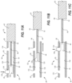
FIG. 11A is a cross-sectional view along axis A-A of a portion of the rotating door handle assembly ofFIG. 3 showing an extension mechanism with a compression member. -
FIG. 11B is a cross-sectional view along axis A-A of the extension mechanism ofFIG. 11A showing the compression member in an intermediate position. -
FIG. 11C is a cross-sectional view along axis A-A of the extension mechanism ofFIG. 11A showing the compression member in a second locked position. -
FIG. 12 is an elevated perspective view of the adjustable handle portion of the rotating door handle assembly ofFIG. 1 , constructed in accordance with the present disclosure. -
FIG. 13 is an elevated perspective view of the adjustable handle portion of the rotating door handle assembly ofFIG. 2 , constructed in accordance with the present disclosure. - Referring now to the drawings, and with specific reference to
FIGS. 1 and 2 , a rotatingdoor handle assembly 20 attached to adoor 22 is shown. The rotatingdoor handle assembly 20 may include a mountingplate 24 that operably and fixedly attaches the rotatingdoor handle assembly 20 to thedoor 22. The mountingplate 24 may further include a lock mechanism (not shown) which provides access to a key or other such paired security device for locking and unlocking thedoor 22. Alternatively, and/or additionally, a keypad (not shown) may be incorporated into the mountingplate 24 and used to enter a code to activate and/or deactivate the lock mechanism. The rotatingdoor handle assembly 20 further includes anadjustable handle portion 28 operably coupled to arotating cylinder 30. Applying an external force to theadjustable handle portion 28 may cause a subsequent rotation or other such movement of therotating cylinder 30 and theadjustable handle portion 28 relative to the mountingplate 24, as illustrated by arrow R. - Furthermore, the rotating
cylinder 30 may be operably coupled to alatch mechanism 32. Thelatch mechanism 32 may include an internal portion disposed within an interior portion of thedoor 22 and an external portion that engages with a latch catch (not shown) of thedoor 22. As such, movement of theadjustable handle portion 28 above or below a longitudinal axis A-A of theadjustable handle portion 28 causes rotation of therotating cylinder 30 in the direction of arrow R (e.g., clockwise or counterclockwise). The rotation of therotating cylinder 30 may activate with thelatch mechanism 32 to retract and disengage the external portion of thelatch mechanism 32 from the latch catch (not shown) so the door may be pulled or pushed open. Conversely, movement to return theadjustable handle portion 28 to a central position along the longitudinal axis A-A may rotate therotating cylinder 30 to extend thelatch mechanism 32 and engage the external portion of the latch mechanism with the latch catch (not shown) to close and secure thedoor 22. It will be understood that the rotatingdoor handle assembly 20 including theadjustable handle portion 28 may be used to open and close a variety of doors such as but not limited to, exterior dwelling unit doors, interior dwelling unit doors, safe or vault doors, aircraft pressurized cabin doors, marine vessel hatch doors and the like. - The
adjustable handle portion 28 has afirst end 34 coupled to therotating cylinder 30 andsecond end 36 that extends axially away from thefirst end 34 along the longitudinal axis A-A of theadjustable handle portion 28. Furthermore, ahandle seam 38 may be defined between thefirst end 34 and thesecond end 36 and thehandle seam 38 may divide theadjustable handle portion 28 into separate portions. In one non-limiting example, anon-extendable handle portion 40 and anextendable handle portion 42 are defined by thehandle seam 38 in theadjustable handle portion 28. Thenon-extendable handle portion 40 is coupled to therotating cylinder 30 and extends from thefirst end 34 to thehandle seam 38. Likewise, theextendable handle portion 42 extends from thehandle seam 38 to thesecond end 36 of theadjustable handle portion 28. Furthermore, it will be understood that thehandle seam 38 may be positioned along theadjustable handle portion 28 to determine a desired size of thenon-extendable handle portion 40, theextendable handle portion 42 or other part of theadjustable handle portion 28. For example, thehandle seam 38 may be defined at a location of theadjustable handle portion 28 such that one of thenon-extendable handle portion 40 and theextendable handle portion 42 is larger than the other. Alternatively, thehandle seam 38 may be defined at a location of theadjustable handle portion 28 such that thenon-extendable handle portion 40 and theextendable handle portion 42 are substantially the same size (i.e., within defined design tolerances). - The
adjustable handle portion 28 further includes ahandle cavity 44 that is formed or otherwise defined within an interior area of theadjustable handle portion 28. In an embodiment, thehandle cavity 44 may have afirst length 45 that extends from thefirst end 34 to thesecond end 36 of theadjustable handle portion 28. In another example, thehandle cavity 44 may have asecond length 47 that extends within a portion of thenon-extendable handle portion 40 and a portion theextendable handle portion 42. In yet another example, thehandle cavity 44 may be defined in only one of thenon-extendable handle portion 40 or theextendable handle portion 42 of theadjustable handle portion 28. Accordingly, it will be understood that thehandle cavity 44 may be sized and configured within thenon-extendable handle portion 40 and theextendable handle portion 42, as needed. - The
handle cavity 44 is configured to enclose abar 46 within thehandle cavity 44 and thebar 46 may extend from thenon-extendable handle portion 40, across thehandle seam 38, and into theextendable handle portion 42. As such, afirst end 48 and asecond end 50 of thebar 46 may each be slidably engaged with an interior surface of thehandle cavity 44 such that applying a force to theextendable handle portion 42 along the longitudinal axis A-A (e.g., pull or push) may extend and/or retract theadjustable handle portion 28. For example,FIG. 1 illustrates theadjustable handle portion 28 in a retractedposition 52 where thenon-extendable handle portion 40 and theextendable handle portion 42 are adjacently positioned with respect to each other. Accordingly, the retractedposition 52 defines afirst handle length 54 of theadjustable handle portion 28, such as but not limited to 5.5 inches. When theadjustable handle portion 28 is in the retractedposition 52 thenon-extendable handle portion 40 and theextendable handle portion 42 may be in direct contact with each other at thehandle seam 38. Furthermore, in the retractedposition 52 thebar 46 may be fully enclosed or otherwise concealed within thehandle cavity 44. Conversely,FIG. 2 illustrates theadjustable handle portion 28 in anextended position 56 where thenon-extendable handle portion 40 andextendable handle portion 42 of theadjustable handle portion 28 are separated from one another with thebar 46 extended therebetween. As such, theextended position 56 may define asecond handle length 58 of theadjustable handle portion 28, such as but not limited to 9.5 inches. - The
adjustable handle portion 28 further includes anextension mechanism 60 configured to facilitate adjustment of theadjustable handle portion 28 between the retractedposition 52 and theextended position 56. In an embodiment, theextension mechanism 60 may be configured such that at least one of thefirst end 48 and thesecond end 50 of thebar 46 is movably and/or slidably engaged with the internal surface of thehandle cavity 44. Accordingly, activation of theextension mechanism 60 using an external force to pull on theadjustable handle portion 28 along the longitudinal axis A-A may cause thenon-extendable handle portion 40 and theextendable handle portion 42 to separate at thehandle seam 38. Thebar 46 may slide along the internal surface of thehandle cavity 44 and axially extend along the longitudinal axis A-A to adjust theadjustable handle portion 28 into theextended position 56. Conversely, activation of theextension mechanism 60 using an external force to push on theadjustable handle portion 28 may cause thenon-extendable handle portion 40 and theextendable handle portion 42 to converge towards each other. Thebar 46 may slide along the internal surface of thehandle cavity 44 and axially retract along the longitudinal axis A-A to adjust theadjustable handle portion 28 into the retractedposition 52. - Turning now to
FIG. 3 , an embodiment of theadjustable handle portion 28 in theextended position 56 including asheath 62 covering a portion of thebar 46 is illustrated. Thesheath 62 may be disposed between thefirst end 48 and thesecond end 50 of thebar 46 to cover the exposed portion of thebar 46 between thenon-extendable handle portion 40 and theextendable handle portion 42 when theadjustable handle portion 28 is in theextended position 56. Furthermore, in an embodiment, thesheath 62 and theadjustable handle portion 28 are made out of the same metal or metal alloy material such as but not limited to, aluminum, stainless steel, brass, polished nickel, chrome, and the like. Thesheath 62 may further include a shape or other such contour that is complimentary to thenon-extendable handle portion 40 and theextendable handle portion 42. For example, when theadjustable handle portion 28 is in theextended position 56 one end of thesheath 62 may be adjacently positioned to a first exposed seam face 64 (FIG. 2 ) on thenon-extendable handle portion 40 and the opposing end of thesheath 62 may be adjacently positioned to a second exposed seam face 66 (FIG. 2 ) on theextendable handle portion 42. As a result, the complimentary shape of thesheath 62 may fit or otherwise pair with the first exposedseam face 64 and the second exposedseam face 66 to give the appearance that thenon-extendable handle portion 40, thesheath 62 and theextendable handle portion 42 form a continuous or unitary structure. - Furthermore,
FIG. 4 shows an alternative embodiment of theadjustable handle portion 28 including acorrugated sheath 68 that covers the exposed portion of the bar 46 (FIG. 2 ) between thenon-extendable handle portion 40 and theextendable handle portion 42 when theadjustable handle portion 28 is in theextended position 56. Similar to thesheath 62 shown inFIG. 3 , thecorrugated sheath 68 may be disposed between the first exposedseam face 64 and the second exposedseam face 66 to cover the exposed portion of thebar 46 between thenon-extendable handle portion 40 and theextendable handle portion 42 when theadjustable handle portion 28 is in theextended position 56. In an embodiment, thecorrugated sheath 68 is formed from rubber, silicone, Viton®, nitrile, neoprene or similar material. Thecorrugated sheath 68 may be sealingly engaged with the first and second exposed seam faces 64, 66 on each of thenon-extendable handle portion 40 and theextendable handle portion 42, respectively. As a result, thecorrugated sheath 68 may form a fluid tight seal between thenon-extendable handle portion 40 and theextendable handle portion 42 that protects thebar 46 and handle cavity 44 (FIGS. 1-4 ) from dust, particles, fluid and other such contaminants present in the external environment. - Referring now to
FIGS. 5A-5C , with continued reference toFIGS. 1-2 , theextension mechanism 60 may be configured to adjust theadjustable handle portion 28 between the retractedposition 52 and theextended position 56. As such, thebar 46 may be slidably engaged with the interior surface of thehandle cavity 44 defined in at least one of thenon-extendable handle portion 40 and theextendable handle portion 42. Furthermore, theextension mechanism 60 may further include atrack system 70 defined to extend along a specified length of thebar 46 and aspring pin 72. In one non-limiting example, thespring pin 72 extends through the outer surface of thenon-extendable handle portion 40. Thespring pin 72 is aligned with an upperlongitudinal channel 73 of thetrack system 70 that is formed in thebar 46. For purposes of simplicity,FIG. 5A illustrates thespring pin 72 extending through thenon-extendable handle portion 40 and thebar 46 but it will be understood thatextension mechanism 60 may be additionally or alternately configured such that thespring pin 72 extends through the outer surface of theextendable handle portion 42. - One non-limiting example of the
spring pin 72 is further illustrated inFIG. 5B . Thespring pin 72 may include abutton 74 defined at one end, a cross-member 76 defined at the opposite end and apin shaft 78 extending therebetween. The cross-member 76 and thepin shaft 78 may generally be perpendicular or orthogonal with respect to one another defining a t-shape. Additionally, thepin shaft 78 may be configured to include a length and diameter that is compatible with dimensions thetrack system 70. Thespring pin 72 further includes aspring 80 or other such elastic element which circumferentially surrounds thepin shaft 78. The top portion of thespring 80 is positioned adjacent to a bottom surface thebutton 74. Thespring pin 72 may be inserted into theextension mechanism 60 such that thespring 80 andbutton 74 are positioned adjacent to the external surface of thenon-extendable handle portion 40 and the cross-member 76 and thepin shaft 78 are aligned with and extend downwards into thetrack system 70. - Moreover, the bottom portion of the
spring 80 may be in direct contact with the external surface of thenon-extendable handle portion 40. Accordingly, thespring 80 biases thespring pin 72 such that the cross-member 76 andpin shaft 78 may be suspended within thetrack system 70. Applying a downward force to the button 74 (i.e., pressing or holding button down) may compress thespring 80 between thebutton 74 and the external surface of thenon-extendable handle portion 40. Subsequently, the compression of thespring 80 along with the downward force may urge thespring pin 72 in the downward direction, as illustrated by arrow D. Conversely, removal of the downward force from the button 74 (i.e., releasing button) may allow thespring 80 to expand back to its original, uncompressed state and the restoring spring force may bias thespring pin 72 in an upward direction, as illustrated by arrow U. - As further illustrated in
FIG. 5C , when theadjustable handle portion 28 is in the retracted position 52 (FIG. 1 ) thespring pin 72 may be in a first locked position 82. Accordingly, in the first locked position 82 the cross-member 76 and a portion of thepin shaft 78 may be suspended within a firstvertical channel 84 of thetrack system 70. Furthermore, in the suspended position, the cross-member 76 and thepin shaft 78 are aligned with and obstructed by a lockingportion 86 of thetrack system 70. Accordingly, interaction between thespring pin 72 and the lockingportion 86 of thetrack system 70 may restrict or otherwise block thebar 46 from sliding in a longitudinal direction represented by the arrow L. - During extension of the
adjustable handle portion 28, applying the downward force on thebutton 74 may urge thespring pin 72 downward in the firstvertical channel 84 such that at least a portion of thespring pin 72 is positioned in a lowerlongitudinal channel 88. As further illustrated inFIG. 5C an intermediate position 91 of thespring pin 72 shown in dashed lines illustrates the cross-member 76 aligned with the lowerlongitudinal channel 88. The lowerlongitudinal channel 88 provides an unobstructed longitudinal pathway for the cross-member 76 and lower portion of thepin shaft 78 within thetrack system 70. Furthermore, the upper portion of thepin shaft 78 remains aligned with the upperlongitudinal channel 73 of thetrack system 70 and thebar 46 becomes free to slide or extend from thenon-extendable handle portion 40. -
FIG. 5C further illustrates a secondvertical channel 90 associated with a second locked position 92 of thetrack system 70. Furthermore, aspring pin 72 is shown in dashed lines as to illustrate the position of thespring pin 72 at the second locked position 92. Once thebar 46 is fully extended the downward force may be removed from thebutton 74 and thespring 80 expands back to its original uncompressed state. Accordingly, the restoring spring force may cause the cross-member 76 and lower portion of thepin shaft 78 to retract in an upward direction through the secondvertical channel 90, as illustrated by arrow U. The secondvertical channel 90 defines the second locked position 92 associated with theextended position 56 of the adjustable handle portion 28 (FIG. 2 ). Similar, to the first locked position 82, when thespring pin 72 is moved into the second locked position 92, the cross-member 76 may be suspended within a secondvertical channel 90 of thetrack system 70 and aligned with a lockingportion 86 of thetrack system 70. As a result, thebar 46 may be locked or otherwise restricted from moving from theextended position 56. To retract thebar 46, and return the handle member to the retracted position 52 (FIG. 1 ), the downward force may be reapplied to thebutton 74 to urge the cross-member 76 downward into the lowerlongitudinal channel 88. Thebar 46 may then slide or otherwise move in the longitudinal direction opposite of arrow L until thespring pin 72 is returned back to the first locked position 82. WhileFIG. 5C illustrates two positions of the spring pin 72 (e.g., first locked position 82 and second locked position 92) it will be understood that thetrack system 70 may include one or more intermediate locking positions to provide additional adjustment points during the extension and/or retraction of theadjustable handle portion 28. -
FIGS. 6 and 7 illustrate anextension mechanism 60 which includes abutton 94 extending from atop surface 95 of thenon-extendable handle portion 40. While thebutton 94 is shown adjacent to and extending away from thetop surface 95 of thenon-extendable handle portion 40, it will be understood thebutton 94 may also be positioned adjacent to a back surface, bottom surface or other such location of thenon-extendable handle portion 40 and/or theextendable handle portion 42. As further illustrated inFIG. 6 , thebutton 94 is operably coupled to aspring pin 96 via alever mechanism 98. Furthermore, thebar 46 includes a plurality ofnotches 100 and thespring pin 96 includes ablock 102 that is normally biased by aspring 104 to interact with one or more notch of the plurality ofnotches 100 to restrict extension and/or retraction of thebar 46. - In one non-limiting example of the
extension mechanism 60 shown inFIG. 6 , thesecond end 50 of thebar 46 is fixedly attached to theextendable handle portion 42 and thefirst end 48 of thebar 46 may longitudinally move within thehandle cavity 44 defined in thenon-extendable handle portion 40.FIG. 6 shows theadjustable handle portion 28 in theextended position 56 and theextension mechanism 60 may be used to adjust theadjustable handle portion 28 between the retracted position 52 (FIG. 1 ), theextended position 56 or an intermediate position in between theextended position 56 and the retracted position 52 (FIG. 1 ). Accordingly, activation of the button 94 (i.e., pressing the button) may cause thelever mechanism 98 to interact with thespring pin 96 to compress thespring 104 and lower or otherwise disengage theblock 102 from the plurality ofnotches 100 defined in thebar 46. As a result, thebar 46 is able to slide or otherwise retract into thehandle cavity 44 towards thefirst end 34 of theadjustable handle portion 28 and theextendable handle portion 42 is able to be adjusted from theextended position 56 to the retracted position 52 (FIG. 1 ) or into one or more intermediate positions therebetween. - In the
extension mechanism 60 illustrated inFIG. 7 , thebutton 94 is operably coupled to thespring pin 96 via alever mechanism 106. Furthermore, afirst magnet 108 is coupled to thelever mechanism 106 and asecond magnet 110 is coupled to thespring 104 of thespring pin 96. Thebar 46 includes the plurality ofnotches 100 and thespring pin 96 includes theblock 102 that is normally biased by thespring 104 to interact with one or more notch of the plurality ofnotches 100 to restrict extension and/or retraction of thebar 46. - In one non-limiting example, the
extension mechanism 60 shown inFIG. 7 may include thesecond end 50 of thebar 46 being fixedly attached to theextendable handle portion 42 and thefirst end 48 of thebar 46 is configured to move longitudinally within thehandle cavity 44 defined within an interior area thenon-extendable handle portion 40. As further shown inFIG. 7 , theadjustable handle portion 28 is in theextended position 56 and theextension mechanism 60 may be used to adjust theadjustable handle portion 28 between the retracted position 52 (FIG. 1 ), theextended position 56 or an intermediate position in between theextended position 56 and the retracted position 52 (FIG. 1 ). - Accordingly, activation of the button 94 (i.e., pressing the button) may cause the
lever mechanism 106 to move thefirst magnet 108 in proximity to thesecond magnet 110 such that thefirst magnet 108 andsecond magnet 110 are attracted towards one another. Such magnetic attraction may create a magnetic flux strong enough to compress thespring 104 and disengage theblock 102 from the plurality ofnotches 100 defined in thebar 46. As a result, thebar 46 is able to slide or otherwise move into thehandle cavity 44 towards thefirst end 34 of theadjustable handle portion 28 and theextendable handle portion 42 is able to be adjusted from theextended position 56 to the retracted position 52 (FIG. 1 ) or into one or more intermediate positions therebetween. - As discussed above, when the
first magnet 108 and thesecond magnet 110 are positioned in proximity to each other a low density magnetic flux of a few Teslas may be produced (e.g., 1-2 Teslas). Furthermore, thespring 104 may be configured with a spring force greater than the magnetic force produced by the first andsecond magnets button 94 is released the larger spring force of thespring 104 will overcome the magnetic force between the first andsecond magnets block 102 to engage or otherwise interfere with one or more of the plurality ofnotches 100 and theextendable handle portion 42 will be restricted from extending and/or retracting. -
FIGS. 8-10 illustrate anextension mechanism 60 which includes aspur gear 112 rotatably mounted within thehandle cavity 44 of thenon-extendable handle portion 40. Thesecond end 50 of thebar 46 may be fixedly attached to theextendable handle portion 42 and thefirst end 48 of thebar 46 may longitudinally move within thehandle cavity 44 defined in thenon-extendable handle portion 40. Furthermore, thebar 46 may include a plurality ofgear teeth 114 which are complimentary to thespur gear 112. Applying an external force (i.e., pulling and/or pushing) on theextendable handle portion 42 may cause thespur gear 112 to rotate along the plurality ofgear teeth 114 to adjust theadjustable handle portion 28 between theextended position 56 or the retracted position 52 (FIG. 1 ). While thespur gear 112 is illustrated being in theextendable handle portion 42 and thebar 46 is fixedly attached to theextendable handle portion 42, it will be understood that thespur gear 112 may alternately be mounted in theextendable handle portion 42 and thebar 46 may be fixedly attached to thenon-extendable handle portion 40. - In one non-limiting example illustrated in
FIG. 8 , thespur gear 112 may be mounted on anaxle 116 that extends vertically within thehandle cavity 44. Moreover, theaxle 116 may extend from an interior bottom surface of thenon-extendable handle portion 40 up to a height within thehandle cavity 44 that aligns thespur gear 112 with the plurality ofgear teeth 114 on thebar 46. As a result, theadjustable handle portion 28 may be adjusted between theextended position 56 and the retractedposition 52 by pulling theextendable handle portion 42 away from thenon-extendable handle portion 40 and/or pushing theextendable handle portion 42 towards thenon-extendable handle portion 40. - Alternatively, as illustrated in
FIG. 9 , thespur gear 112 may be rotatably mounted to agear bracket 118 that is coupled to an internal top surface of thenon-extendable handle portion 40. Accordingly, thespur gear 112 is suspended within thehandle cavity 44 from the internal top surface of thenon-extendable handle portion 40 and thegear bracket 118 is configured to position thespur gear 112 to mesh or otherwise interact with thegear teeth 114 along thebar 46. Thus, theadjustable handle portion 28 may be adjusted between theextended position 56 and the retractedposition 52 by pulling theextendable handle portion 42 away from thenon-extendable handle portion 40 and/or pushing theextendable handle portion 42 towards thenon-extendable handle portion 40. - As further illustrated in
FIG. 10 , thegear bracket 118 may be operably coupled to abutton 122 that extends through the internaltop surface 120 to an externaltop surface 124 of thenon-extendable handle portion 40. When thebutton 122 is in a non-activated state, thegear bracket 118 may position the spur gear 112 a specified distance above thebar 46 such that thespur gear 112 and the plurality ofgear teeth 114 are not in contact or otherwise meshed with one another. As a result, theadjustable handle portion 28 may be in a locked state and thenon-extendable handle portion 40 and theextendable handle portion 42 may not be adjusted between the retractedposition 52 and theextended position 56. Activation (i.e., pressing) of thebutton 122 may actuate or otherwise move thegear bracket 118 and thespur gear 112 downwards towards thebar 46 to engage the plurality ofgear teeth 114 defined along thebar 46. Accordingly, when thespur gear 112 andgear teeth 114 come into contact with each other and theadjustable handle portion 28 may be adjusted into either theextended position 56 and/or the retractedposition 52 by pulling theextendable handle portion 42 away from thenon-extendable handle portion 40 or pushing theextendable handle portion 42 towards thenon-extendable handle portion 40. - Referring now to
FIGS. 11A-11C , an extension mechanism includingcompression U-slider 126 is shown. Thecompression U-slider 126 is disposed within thehandle cavity 44 of thenon-extendable handle portion 40. Furthermore, thecompression U-slider 126 is disposed between a firstinterior surface 128 and an opposing secondinterior surface 130 of thenon-extendable handle portion 40 such that a portion of thecompression U-slider 126 is in direct contact with the firstinterior surface 128 and the secondinterior surface 130. Moreover, thefirst end 48 of thebar 46 is fixedly attached to the compression U-slider 126 and thesecond end 50 of thebar 46 is fixedly attached to theextendable handle portion 42. Thetop surface 95 of thenon-extendable handle portion 40 may include a retractedlocking position 132 associated with the retractedposition 52 and anextended locking position 134 associated with theextended position 56. The retracted andextended locking positions top surface 95 of thenon-extendable handle portion 40. Thecompression U-slider 126 may further include atab 136 configured to align with and extend through the retracted andextended locking positions compression U-slider 126. - As illustrated in
FIG. 11A , theadjustable handle portion 28 is in the retractedposition 52. Thetab 136 of thecompression U-slider 126 is engaged or otherwise locked into the retractedlocking position 132. Accordingly, thenon-extendable handle portion 40 and theextendable handle portion 42 are adjacently positioned along thehandle seam 38 and thebar 46 is retracted within thehandle cavity 44. Applying an external pressure (i.e., pressing) on thetab 136 as illustrated by the arrow inFIG. 11A , may compress the compression U-slider 126 and urge thetab 136 into thehandle cavity 44. Such movement of thetab 136 may disengage or unlock the compression U-slider from the retractedlocking position 132 and theadjustable handle portion 28 may be adjusted between theextended position 56 and the retractedposition 52 by pulling theextendable handle portion 42 away from thenon-extendable handle portion 40 and/or pushing theextendable handle portion 42 towards thenon-extendable handle portion 40. -
FIG. 11B illustrates the extension and/or retraction of theadjustable handle portion 28. During the adjustment between the retractedposition 52 and theextended position 56 thecompression U-slider 126 is compressed within thehandle cavity 44 such that thetab 136 is slidably engaged with the firstinterior surface 128 and an opposing portion of thecompression U-slider 126 is engaged with the secondinterior surface 130 of thenon-extendable handle portion 40. As further illustrated inFIG 11B , applying an external force on theextendable handle portion 42 in the direction of the arrow will cause thenon-extendable handle portion 40 andextendable handle portion 42 to separate from each other at thehandle seam 38. Thecompression U-slider 126 may continue to slide along the first and secondinterior surfaces tab 136 reaches theextended locking position 134. -
FIG. 11C illustrates theadjustable handle portion 28 in theextended position 56 and thecompression U-slider 126 being engaged with or otherwise locked into theextended locking position 134. As discussed above, during the extension of theadjustable handle portion 28, thecompression U-slider 126 may slide along the first and secondinterior surfaces non-extendable handle portion 40. When thetab 136 reaches theextended locking position 134, the compression U-slider may expand such that thetab 136 is urged into theextended locking position 134, as illustrated by the arrow. Accordingly, the adjustable handle portion is in theextended position 56 and thenon-extendable handle portion 40 and theextendable handle portion 42 are separated from one another with thebar 46 extending from thehandle cavity 44 and disposed therebetween. WhileFIGS. 11A-11C show the retracted andextended locking positions non-extendable handle portion 40 andextendable handle portion 42. - In general, the teachings of the present disclosure may find applicability in many industries including building construction and decorating industries. More specifically, the rotating door handle assembly of the present disclosure may be applicable to building and residence construction according to aging-in-place practices by providing an adjustable handle portion that includes an extension mechanism to easily adjust the handle length. Moreover, individuals with certain physical limitations brought on by advanced age or other physical conditions may experience difficulty operating doors with rotating door handles. As a result, door handles that can be adjusted between a standard and extended length may provide some benefit because the force required to twist or rotate a door handle decreases with an increase in handle length. Additionally, rotating door handle assemblies with an adjustable handle may be desirable because a single handle design can be used throughout a building. Additionally, the adjustable handle may be compliant with the Americans with Disabilities Act (ADA) guidelines and design standards for ease of use and requirements of rotating door handle assemblies used to open a larger sized door.
-
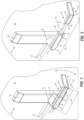
FIG. 12 shows a retractedhandle displacement 138 of theadjustable handle portion 28 when theadjustable handle portion 28 is adjusted into thefirst handle length 54 associated with the retractedposition 52. In one non-limiting example, thefirst handle length 54 is approximately 5.5 inches; however, it will be understood that other lengths are possible. Accordingly, when anexternal force 140 is applied to theadjustable handle portion 28, the rotatingdoor handle assembly 20 is displaced from a retractedhandle starting position 142, illustrated by the dotted outline of theadjustable handle portion 28, to a retractedhandle ending position 144. Accordingly, the retracteddisplacement handle 138 is measured as the distance between the retractedhandle starting position 142 and the retractedhandle ending position 144. Furthermore, in one non-limiting example theexternal force 140 applied to theadjustable handle portion 28 is equal to 8 poundsforce (lbf), however other force magnitudes may be used. -
FIG. 13 , with continued reference toFIG. 12 shows anextended handle displacement 146 of theadjustable handle portion 28 when theadjustable handle portion 28 is adjusted into thesecond handle length 58 associated with theextended position 56. In one non-limiting example, thesecond handle length 58 is approximately 9.5 inches; however, it will be understood that other lengths are possible. Accordingly, when the same external force 140 (e.g., 8 lbf) is applied to theadjustable handle portion 28, as shown inFIG. 13 , theadjustable handle portion 28 is displaced from an extendedhandle starting position 148, illustrated by the dotted outline of theadjustable handle portion 28, to an extendedhandle ending position 150. Accordingly, theextended handle displacement 146 is measured as the distance between the extendedhandle starting position 148 and the extendedhandle ending position 150. As stated above, in this non-limiting example theexternal force 140 applied to theadjustable handle portion 28 in the retractedposition 52 and theextended position 56 is equal to 8 lbf, however other force amounts may be used. - A difference between the retracted
handle displacement 138 and theextended handle displacement 146 was measured when an equal external force 140 (e.g., 8 lbf) was applied to theadjustable handle portion 28 in the retractedposition 52 and theextended position 56. In one non-limiting example, the totalextended handle displacement 146 was about three times the magnitude of the total retractedhandle displacement 138. In other words, when an equal force is applied to a shorter handle and a longer handle, the longer handle will have a larger displacement. Furthermore, it may be reasoned that a lower external force may be required to act on the adjustable handle in theextended position 56 to produce theextended handle displacement 146 that is equal to the retractedhandle displacement 138. Thus, in some cases, a longer length door handle may allow a door to be opened using a lower amount of force. - While the preceding text sets forth a detailed description of numerous different embodiments, it should be understood that the legal scope of protection is defined by the words of the claims set forth at the end of this patent. The detailed description is to be construed as exemplary only and does not describe every possible embodiment since describing every possible embodiment would be impractical, if not impossible. Numerous alternative embodiments could be implemented, using either current technology or technology developed after the filing date of this patent, which would still fall within the scope of the appended claims defining the scope of protection.
- It should also be understood that, unless a term was expressly defined herein, there is no intent to limit the meaning of that term, either expressly or by implication, beyond its plain or ordinary meaning, and such term should not be interpreted to be limited in scope based on any statement made in any section of this patent (other than the language of the claims). To the extent that any term recited in the claims at the end of this patent is referred to herein in a manner consistent with a single meaning, that is done for sake of clarity only to not confuse the reader, and it is not intended that such claim term be limited, by implication or otherwise, to that single meaning.
Claims (3)
- A handle comprising:a first member (28), wherein a length of the first member is adjustable; anda bar (46) extendably coupled between a non-extendable portion (40) and an extendable portion (42) of the first member;wherein a cavity (44) is defined within a portion of at least one of the non-extendable portion and the extendable portion, and wherein the bar is enclosed within the cavity when the first member is in a non-extended position (52) and the bar is extended from the cavity between the non-extendable portion and the extendable portion when the first member is in an extended position (56);wherein the handle further comprises an extension mechanism (60) operably engaged with the non-extendable portion, the extendable portion, and the bar, wherein the extension mechanism is configured to extend the bar between the non-extendable portion and the extendable portion when the first member is in the extended position and retract the bar within the cavity when the first member is in the non-extended position;whereinthe handle further comprises a second rotatable member (30) configured to engage a door latch mechanism (32), wherein the second rotatable member is mechanically engaged with the first member; characterized in that:the extension mechanism includes a spring pin (96) and a button (94) operably coupled to the spring pin, and wherein activation of the button and the spring pin allows the bar to adjust the first member between the extended position and the non-extended position;the button is operably coupled to a lever mechanism (106) and the spring pin engages with a plurality of notches (100) defined along the bar, and wherein activation of the button causes the lever mechanism to disengage the spring pin from the plurality of notches to allow the bar to adjust the first member between the extended position and the non-extended position; andthe button is further coupled to a first magnet (108) and the spring pin is coupled to a second magnet (110), and wherein activation of the button causes the lever mechanism to adjacently position the first magnet and the second magnet such that the first and second magnets are attracted towards each other to disengage the spring pin from the plurality of notches to allow the bar to adjust the first member between the extended position (56) and the non-extended position.
- The handle of claim 1, further comprising a sheath portion (62) configured to cover a portion of the bar (46) between the non-extendable portion (40) and the extendable portion (42) when the first member (28) is in the extended position (56).
- A door handle assembly (20) operably coupled to a door (22), the door handle assembly comprising:the handle of claim 1;the door latch mechanism (32) operably coupled to the door; anda mounting plate (24) attached to a surface of the door, wherein the second rotatable member (30) is coupled to the mounting plate.
Applications Claiming Priority (2)
| Application Number | Priority Date | Filing Date | Title |
|---|---|---|---|
| US16/012,221 US11454045B2 (en) | 2018-06-19 | 2018-06-19 | Rotating door handle for ease of use |
| PCT/US2019/033761 WO2019245701A1 (en) | 2018-06-19 | 2019-05-23 | Rotating door handle for ease of use |
Publications (2)
| Publication Number | Publication Date |
|---|---|
| EP3810872A1 EP3810872A1 (en) | 2021-04-28 |
| EP3810872B1 true EP3810872B1 (en) | 2025-04-02 |
Family
ID=66998477
Family Applications (1)
| Application Number | Title | Priority Date | Filing Date |
|---|---|---|---|
| EP19732158.1A Active EP3810872B1 (en) | 2018-06-19 | 2019-05-23 | Rotating door handle for ease of use |
Country Status (5)
| Country | Link |
|---|---|
| US (1) | US11454045B2 (en) |
| EP (1) | EP3810872B1 (en) |
| CA (1) | CA3104617A1 (en) |
| ES (1) | ES3029734T3 (en) |
| WO (1) | WO2019245701A1 (en) |
Families Citing this family (3)
| Publication number | Priority date | Publication date | Assignee | Title |
|---|---|---|---|---|
| US10920449B1 (en) * | 2019-08-27 | 2021-02-16 | Luuv Inc | Handle adapter for sliding glass doors |
| CN111852184B (en) * | 2020-07-09 | 2021-11-23 | 深圳市慢工坊智能家居有限公司 | Fingerprint lock |
| US20250354419A1 (en) * | 2024-05-20 | 2025-11-20 | The Boeing Company | Door latch apparatus and associated system and method |
Citations (2)
| Publication number | Priority date | Publication date | Assignee | Title |
|---|---|---|---|---|
| JPH10252320A (en) * | 1997-03-13 | 1998-09-22 | Ykk Architect Prod Kk | Extensible handle |
| DE102013200203B3 (en) * | 2013-01-09 | 2014-06-18 | Egon Maurer | Door handle for opening and closing door of door lock for use by e.g. young children, has hollow rope like or telescopically formed tensile element rolled up automatically by retractor element, which is integrated in door leaf by spring |
Family Cites Families (5)
| Publication number | Priority date | Publication date | Assignee | Title |
|---|---|---|---|---|
| US2486586A (en) * | 1945-03-07 | 1949-11-01 | Brittain Bert | Flush handle construction |
| DE10217770A1 (en) * | 2001-07-11 | 2003-01-30 | Melchert Beschlaege | Latch handle has pivot projecting across axial direction of neck and rooted in mitre section of same adjoined by planar face of inclined cylindrical interchangeable spacer member |
| US7270352B1 (en) * | 2004-07-20 | 2007-09-18 | Robert Stuart | Foot-operated door opener |
| DE102005037041A1 (en) * | 2005-08-05 | 2007-02-08 | Hewi Heinrich Wilke Gmbh | Panic bar or panic grip |
| US9999970B2 (en) * | 2016-09-28 | 2018-06-19 | Don Robert Browning | Telescoping handle device |
-
2018
- 2018-06-19 US US16/012,221 patent/US11454045B2/en active Active
-
2019
- 2019-05-23 EP EP19732158.1A patent/EP3810872B1/en active Active
- 2019-05-23 WO PCT/US2019/033761 patent/WO2019245701A1/en not_active Ceased
- 2019-05-23 ES ES19732158T patent/ES3029734T3/en active Active
- 2019-05-23 CA CA3104617A patent/CA3104617A1/en active Pending
Patent Citations (2)
| Publication number | Priority date | Publication date | Assignee | Title |
|---|---|---|---|---|
| JPH10252320A (en) * | 1997-03-13 | 1998-09-22 | Ykk Architect Prod Kk | Extensible handle |
| DE102013200203B3 (en) * | 2013-01-09 | 2014-06-18 | Egon Maurer | Door handle for opening and closing door of door lock for use by e.g. young children, has hollow rope like or telescopically formed tensile element rolled up automatically by retractor element, which is integrated in door leaf by spring |
Also Published As
| Publication number | Publication date |
|---|---|
| WO2019245701A1 (en) | 2019-12-26 |
| CA3104617A1 (en) | 2019-12-26 |
| US11454045B2 (en) | 2022-09-27 |
| ES3029734T3 (en) | 2025-06-25 |
| EP3810872A1 (en) | 2021-04-28 |
| US20190383055A1 (en) | 2019-12-19 |
Similar Documents
| Publication | Publication Date | Title |
|---|---|---|
| US11454045B2 (en) | Rotating door handle for ease of use | |
| EP2833754B1 (en) | Closure device for detachably connecting two parts | |
| EP1907655B1 (en) | Security system for entrance barriers | |
| EP2318626B1 (en) | Magnetic safety latch | |
| US8931813B2 (en) | Rotary lock providing positive latching indicia | |
| US4159838A (en) | Door latch bolt locking device | |
| DE112016004844T5 (en) | Door handle for a vehicle | |
| EP2435648B1 (en) | Device for locking second leaves in the closed configuration | |
| EP0967351A3 (en) | Espagnolette lock | |
| EP2525027A2 (en) | Privacy latch | |
| US5669256A (en) | Door lock mechanism with a release button | |
| DE19957697A1 (en) | Door opener for windows and doors has square edge and door opening element which can only be operated against spring action to act as child lock | |
| DE102010028647B3 (en) | Lock for use with access control device for door, has lock mechanism controlling latch bolt or bar and actuating handle which is coupled with lock mechanism for actuating latch bolt or bar by pre-loaded spring | |
| CN208792902U (en) | Door lock | |
| DE202015004163U1 (en) | Handicapped bar fitting with smooth surface, emergency release and freewheel for opening closing elements | |
| EP0866208A3 (en) | Roller Shutter | |
| EP3385473B1 (en) | Spindle apparatus and method of forming thereof | |
| EP2407617B1 (en) | Door with manually actuatable handle | |
| EP3660247A1 (en) | Lock and button mechanism for use in a door or a window | |
| EP3091151A1 (en) | Driving rod lock for a driving rod fitting | |
| US3287056A (en) | Lock push button control | |
| CA2695301C (en) | Safety lock | |
| JP2005036403A (en) | Flat lock mechanism | |
| EP3911821B1 (en) | Panel closure apparatus | |
| EP3775447B1 (en) | Closing device for sliding doors/windows |
Legal Events
| Date | Code | Title | Description |
|---|---|---|---|
| STAA | Information on the status of an ep patent application or granted ep patent |
Free format text: STATUS: UNKNOWN |
|
| STAA | Information on the status of an ep patent application or granted ep patent |
Free format text: STATUS: THE INTERNATIONAL PUBLICATION HAS BEEN MADE |
|
| PUAI | Public reference made under article 153(3) epc to a published international application that has entered the european phase |
Free format text: ORIGINAL CODE: 0009012 |
|
| STAA | Information on the status of an ep patent application or granted ep patent |
Free format text: STATUS: REQUEST FOR EXAMINATION WAS MADE |
|
| 17P | Request for examination filed |
Effective date: 20201222 |
|
| AK | Designated contracting states |
Kind code of ref document: A1 Designated state(s): AL AT BE BG CH CY CZ DE DK EE ES FI FR GB GR HR HU IE IS IT LI LT LU LV MC MK MT NL NO PL PT RO RS SE SI SK SM TR |
|
| AX | Request for extension of the european patent |
Extension state: BA ME |
|
| RAP1 | Party data changed (applicant data changed or rights of an application transferred) |
Owner name: ARCONIC TECHNOLOGIES LLC |
|
| DAV | Request for validation of the european patent (deleted) | ||
| DAX | Request for extension of the european patent (deleted) | ||
| P01 | Opt-out of the competence of the unified patent court (upc) registered |
Effective date: 20230517 |
|
| STAA | Information on the status of an ep patent application or granted ep patent |
Free format text: STATUS: EXAMINATION IS IN PROGRESS |
|
| 17Q | First examination report despatched |
Effective date: 20231027 |
|
| GRAP | Despatch of communication of intention to grant a patent |
Free format text: ORIGINAL CODE: EPIDOSNIGR1 |
|
| STAA | Information on the status of an ep patent application or granted ep patent |
Free format text: STATUS: GRANT OF PATENT IS INTENDED |
|
| INTG | Intention to grant announced |
Effective date: 20241030 |
|
| GRAS | Grant fee paid |
Free format text: ORIGINAL CODE: EPIDOSNIGR3 |
|
| GRAA | (expected) grant |
Free format text: ORIGINAL CODE: 0009210 |
|
| STAA | Information on the status of an ep patent application or granted ep patent |
Free format text: STATUS: THE PATENT HAS BEEN GRANTED |
|
| AK | Designated contracting states |
Kind code of ref document: B1 Designated state(s): AL AT BE BG CH CY CZ DE DK EE ES FI FR GB GR HR HU IE IS IT LI LT LU LV MC MK MT NL NO PL PT RO RS SE SI SK SM TR |
|
| REG | Reference to a national code |
Ref country code: GB Ref legal event code: FG4D |
|
| RIN1 | Information on inventor provided before grant (corrected) |
Inventor name: MILLER, MATTHEW M. |
|
| REG | Reference to a national code |
Ref country code: CH Ref legal event code: EP |
|
| REG | Reference to a national code |
Ref country code: IE Ref legal event code: FG4D |
|
| REG | Reference to a national code |
Ref country code: DE Ref legal event code: R096 Ref document number: 602019068071 Country of ref document: DE |
|
| REG | Reference to a national code |
Ref country code: NL Ref legal event code: FP |
|
| PGFP | Annual fee paid to national office [announced via postgrant information from national office to epo] |
Ref country code: NL Payment date: 20250520 Year of fee payment: 7 |
|
| REG | Reference to a national code |
Ref country code: ES Ref legal event code: FG2A Ref document number: 3029734 Country of ref document: ES Kind code of ref document: T3 Effective date: 20250625 |
|
| PGFP | Annual fee paid to national office [announced via postgrant information from national office to epo] |
Ref country code: DE Payment date: 20250423 Year of fee payment: 7 |
|
| PGFP | Annual fee paid to national office [announced via postgrant information from national office to epo] |
Ref country code: GB Payment date: 20250520 Year of fee payment: 7 Ref country code: ES Payment date: 20250604 Year of fee payment: 7 |
|
| PGFP | Annual fee paid to national office [announced via postgrant information from national office to epo] |
Ref country code: BE Payment date: 20250516 Year of fee payment: 7 |
|
| PGFP | Annual fee paid to national office [announced via postgrant information from national office to epo] |
Ref country code: FR Payment date: 20250520 Year of fee payment: 7 |
|
| REG | Reference to a national code |
Ref country code: AT Ref legal event code: MK05 Ref document number: 1781410 Country of ref document: AT Kind code of ref document: T Effective date: 20250402 |
|
| PG25 | Lapsed in a contracting state [announced via postgrant information from national office to epo] |
Ref country code: PT Free format text: LAPSE BECAUSE OF FAILURE TO SUBMIT A TRANSLATION OF THE DESCRIPTION OR TO PAY THE FEE WITHIN THE PRESCRIBED TIME-LIMIT Effective date: 20250804 Ref country code: FI Free format text: LAPSE BECAUSE OF FAILURE TO SUBMIT A TRANSLATION OF THE DESCRIPTION OR TO PAY THE FEE WITHIN THE PRESCRIBED TIME-LIMIT Effective date: 20250402 |
|
| REG | Reference to a national code |
Ref country code: LT Ref legal event code: MG9D |
|
| PG25 | Lapsed in a contracting state [announced via postgrant information from national office to epo] |
Ref country code: NO Free format text: LAPSE BECAUSE OF FAILURE TO SUBMIT A TRANSLATION OF THE DESCRIPTION OR TO PAY THE FEE WITHIN THE PRESCRIBED TIME-LIMIT Effective date: 20250702 Ref country code: GR Free format text: LAPSE BECAUSE OF FAILURE TO SUBMIT A TRANSLATION OF THE DESCRIPTION OR TO PAY THE FEE WITHIN THE PRESCRIBED TIME-LIMIT Effective date: 20250703 |
|
| PG25 | Lapsed in a contracting state [announced via postgrant information from national office to epo] |
Ref country code: PL Free format text: LAPSE BECAUSE OF FAILURE TO SUBMIT A TRANSLATION OF THE DESCRIPTION OR TO PAY THE FEE WITHIN THE PRESCRIBED TIME-LIMIT Effective date: 20250402 |
|
| PG25 | Lapsed in a contracting state [announced via postgrant information from national office to epo] |
Ref country code: BG Free format text: LAPSE BECAUSE OF FAILURE TO SUBMIT A TRANSLATION OF THE DESCRIPTION OR TO PAY THE FEE WITHIN THE PRESCRIBED TIME-LIMIT Effective date: 20250402 |
|
| PG25 | Lapsed in a contracting state [announced via postgrant information from national office to epo] |
Ref country code: HR Free format text: LAPSE BECAUSE OF FAILURE TO SUBMIT A TRANSLATION OF THE DESCRIPTION OR TO PAY THE FEE WITHIN THE PRESCRIBED TIME-LIMIT Effective date: 20250402 |
|
| PG25 | Lapsed in a contracting state [announced via postgrant information from national office to epo] |
Ref country code: AT Free format text: LAPSE BECAUSE OF FAILURE TO SUBMIT A TRANSLATION OF THE DESCRIPTION OR TO PAY THE FEE WITHIN THE PRESCRIBED TIME-LIMIT Effective date: 20250402 |
|
| PG25 | Lapsed in a contracting state [announced via postgrant information from national office to epo] |
Ref country code: RS Free format text: LAPSE BECAUSE OF FAILURE TO SUBMIT A TRANSLATION OF THE DESCRIPTION OR TO PAY THE FEE WITHIN THE PRESCRIBED TIME-LIMIT Effective date: 20250702 |
|
| REG | Reference to a national code |
Ref country code: DE Ref legal event code: R081 Ref document number: 602019068071 Country of ref document: DE Owner name: KAWNEER COMPANY, INC. (N.D.GES.D. STAATES DELA, US Free format text: FORMER OWNER: ARCONIC TECHNOLOGIES LLC, PITTSBURGH, PA, US |
|
| PG25 | Lapsed in a contracting state [announced via postgrant information from national office to epo] |
Ref country code: IS Free format text: LAPSE BECAUSE OF FAILURE TO SUBMIT A TRANSLATION OF THE DESCRIPTION OR TO PAY THE FEE WITHIN THE PRESCRIBED TIME-LIMIT Effective date: 20250802 |
|
| PG25 | Lapsed in a contracting state [announced via postgrant information from national office to epo] |
Ref country code: LV Free format text: LAPSE BECAUSE OF FAILURE TO SUBMIT A TRANSLATION OF THE DESCRIPTION OR TO PAY THE FEE WITHIN THE PRESCRIBED TIME-LIMIT Effective date: 20250402 |
|
| REG | Reference to a national code |
Ref country code: NL Ref legal event code: PD Owner name: KAWNEER COMPANY, INC.; US Free format text: DETAILS ASSIGNMENT: CHANGE OF OWNER(S), ASSIGNMENT; FORMER OWNER NAME: ARCONIC TECHNOLOGIES LLC Effective date: 20251103 |
|
| REG | Reference to a national code |
Ref country code: GB Ref legal event code: 732E Free format text: REGISTERED BETWEEN 20251106 AND 20251112 |
|
| REG | Reference to a national code |
Ref country code: CH Ref legal event code: H13 Free format text: ST27 STATUS EVENT CODE: U-0-0-H10-H13 (AS PROVIDED BY THE NATIONAL OFFICE) Effective date: 20251223 |
|
| REG | Reference to a national code |
Ref country code: DE Ref legal event code: R097 Ref document number: 602019068071 Country of ref document: DE |
|
| PG25 | Lapsed in a contracting state [announced via postgrant information from national office to epo] |
Ref country code: DK Free format text: LAPSE BECAUSE OF FAILURE TO SUBMIT A TRANSLATION OF THE DESCRIPTION OR TO PAY THE FEE WITHIN THE PRESCRIBED TIME-LIMIT Effective date: 20250402 Ref country code: SM Free format text: LAPSE BECAUSE OF FAILURE TO SUBMIT A TRANSLATION OF THE DESCRIPTION OR TO PAY THE FEE WITHIN THE PRESCRIBED TIME-LIMIT Effective date: 20250402 |
|
| PG25 | Lapsed in a contracting state [announced via postgrant information from national office to epo] |
Ref country code: LU Free format text: LAPSE BECAUSE OF NON-PAYMENT OF DUE FEES Effective date: 20250523 |
|
| REG | Reference to a national code |
Ref country code: BE Ref legal event code: PD Owner name: KAWNEER COMPANY, INC.; US Free format text: DETAILS ASSIGNMENT: CHANGE OF OWNER(S), ASSIGNMENT; FORMER OWNER NAME: ARCONIC TECHNOLOGIES LLC Effective date: 20251113 |
|
| PG25 | Lapsed in a contracting state [announced via postgrant information from national office to epo] |
Ref country code: CH Free format text: LAPSE BECAUSE OF NON-PAYMENT OF DUE FEES Effective date: 20250531 |
|
| PG25 | Lapsed in a contracting state [announced via postgrant information from national office to epo] |
Ref country code: CZ Free format text: LAPSE BECAUSE OF FAILURE TO SUBMIT A TRANSLATION OF THE DESCRIPTION OR TO PAY THE FEE WITHIN THE PRESCRIBED TIME-LIMIT Effective date: 20250402 |
|
| PG25 | Lapsed in a contracting state [announced via postgrant information from national office to epo] |
Ref country code: EE Free format text: LAPSE BECAUSE OF FAILURE TO SUBMIT A TRANSLATION OF THE DESCRIPTION OR TO PAY THE FEE WITHIN THE PRESCRIBED TIME-LIMIT Effective date: 20250402 |
|
| PG25 | Lapsed in a contracting state [announced via postgrant information from national office to epo] |
Ref country code: SK Free format text: LAPSE BECAUSE OF FAILURE TO SUBMIT A TRANSLATION OF THE DESCRIPTION OR TO PAY THE FEE WITHIN THE PRESCRIBED TIME-LIMIT Effective date: 20250402 Ref country code: RO Free format text: LAPSE BECAUSE OF FAILURE TO SUBMIT A TRANSLATION OF THE DESCRIPTION OR TO PAY THE FEE WITHIN THE PRESCRIBED TIME-LIMIT Effective date: 20250402 |
|
| PG25 | Lapsed in a contracting state [announced via postgrant information from national office to epo] |
Ref country code: IT Free format text: LAPSE BECAUSE OF FAILURE TO SUBMIT A TRANSLATION OF THE DESCRIPTION OR TO PAY THE FEE WITHIN THE PRESCRIBED TIME-LIMIT Effective date: 20250402 |
|
| PG25 | Lapsed in a contracting state [announced via postgrant information from national office to epo] |
Ref country code: MC Free format text: LAPSE BECAUSE OF FAILURE TO SUBMIT A TRANSLATION OF THE DESCRIPTION OR TO PAY THE FEE WITHIN THE PRESCRIBED TIME-LIMIT Effective date: 20250402 |
|
| PLBE | No opposition filed within time limit |
Free format text: ORIGINAL CODE: 0009261 |
|
| STAA | Information on the status of an ep patent application or granted ep patent |
Free format text: STATUS: NO OPPOSITION FILED WITHIN TIME LIMIT |
|
| REG | Reference to a national code |
Ref country code: CH Ref legal event code: L10 Free format text: ST27 STATUS EVENT CODE: U-0-0-L10-L00 (AS PROVIDED BY THE NATIONAL OFFICE) Effective date: 20260211 |
|
| 26N | No opposition filed |
Effective date: 20260105 |
|
| PG25 | Lapsed in a contracting state [announced via postgrant information from national office to epo] |
Ref country code: IE Free format text: LAPSE BECAUSE OF NON-PAYMENT OF DUE FEES Effective date: 20250523 |