EP3809805A1 - Component carrier and method of manufacturing the same - Google Patents
Component carrier and method of manufacturing the same Download PDFInfo
- Publication number
- EP3809805A1 EP3809805A1 EP19203022.9A EP19203022A EP3809805A1 EP 3809805 A1 EP3809805 A1 EP 3809805A1 EP 19203022 A EP19203022 A EP 19203022A EP 3809805 A1 EP3809805 A1 EP 3809805A1
- Authority
- EP
- European Patent Office
- Prior art keywords
- component
- component carrier
- base structure
- carrier
- copper layer
- Prior art date
- Legal status (The legal status is an assumption and is not a legal conclusion. Google has not performed a legal analysis and makes no representation as to the accuracy of the status listed.)
- Granted
Links
Images






Classifications
-
- H—ELECTRICITY
- H05—ELECTRIC TECHNIQUES NOT OTHERWISE PROVIDED FOR
- H05K—PRINTED CIRCUITS; CASINGS OR CONSTRUCTIONAL DETAILS OF ELECTRIC APPARATUS; MANUFACTURE OF ASSEMBLAGES OF ELECTRICAL COMPONENTS
- H05K1/00—Printed circuits
- H05K1/18—Printed circuits structurally associated with non-printed electric components
- H05K1/182—Printed circuits structurally associated with non-printed electric components associated with components mounted in printed circuit boards [PCB], e.g. insert-mounted components [IMC]
- H05K1/185—Printed circuits structurally associated with non-printed electric components associated with components mounted in printed circuit boards [PCB], e.g. insert-mounted components [IMC] associated with components encapsulated in the insulating substrate of the PCBs; associated with components incorporated in internal layers of multilayer circuit boards
- H05K1/188—Printed circuits structurally associated with non-printed electric components associated with components mounted in printed circuit boards [PCB], e.g. insert-mounted components [IMC] associated with components encapsulated in the insulating substrate of the PCBs; associated with components incorporated in internal layers of multilayer circuit boards manufactured by mounting on or attaching to a structure having a conductive layer, e.g. a metal foil, such that the terminals of the component are connected to or adjacent to the conductive layer before embedding, and by using the conductive layer, which is patterned after embedding, at least partially for connecting the component
-
- H—ELECTRICITY
- H10—SEMICONDUCTOR DEVICES; ELECTRIC SOLID-STATE DEVICES NOT OTHERWISE PROVIDED FOR
- H10W—GENERIC PACKAGES, INTERCONNECTIONS, CONNECTORS OR OTHER CONSTRUCTIONAL DETAILS OF DEVICES COVERED BY CLASS H10
- H10W70/00—Package substrates; Interposers; Redistribution layers [RDL]
- H10W70/01—Manufacture or treatment
- H10W70/05—Manufacture or treatment of insulating or insulated package substrates, or of interposers, or of redistribution layers
- H10W70/08—Manufacture or treatment of insulating or insulated package substrates, or of interposers, or of redistribution layers by depositing layers on the chip or wafer, e.g. "chip-first" RDLs
- H10W70/09—Manufacture or treatment of insulating or insulated package substrates, or of interposers, or of redistribution layers by depositing layers on the chip or wafer, e.g. "chip-first" RDLs extending onto an encapsulation that laterally surrounds the chip or wafer, e.g. fan-out wafer level package [FOWLP] RDLs
-
- H—ELECTRICITY
- H05—ELECTRIC TECHNIQUES NOT OTHERWISE PROVIDED FOR
- H05K—PRINTED CIRCUITS; CASINGS OR CONSTRUCTIONAL DETAILS OF ELECTRIC APPARATUS; MANUFACTURE OF ASSEMBLAGES OF ELECTRICAL COMPONENTS
- H05K1/00—Printed circuits
- H05K1/02—Details
- H05K1/0201—Thermal arrangements, e.g. for cooling, heating or preventing overheating
- H05K1/0203—Cooling of mounted components
-
- H—ELECTRICITY
- H05—ELECTRIC TECHNIQUES NOT OTHERWISE PROVIDED FOR
- H05K—PRINTED CIRCUITS; CASINGS OR CONSTRUCTIONAL DETAILS OF ELECTRIC APPARATUS; MANUFACTURE OF ASSEMBLAGES OF ELECTRICAL COMPONENTS
- H05K1/00—Printed circuits
- H05K1/02—Details
- H05K1/0201—Thermal arrangements, e.g. for cooling, heating or preventing overheating
- H05K1/0203—Cooling of mounted components
- H05K1/0207—Cooling of mounted components using internal conductor planes parallel to the surface for thermal conduction, e.g. power planes
-
- H—ELECTRICITY
- H05—ELECTRIC TECHNIQUES NOT OTHERWISE PROVIDED FOR
- H05K—PRINTED CIRCUITS; CASINGS OR CONSTRUCTIONAL DETAILS OF ELECTRIC APPARATUS; MANUFACTURE OF ASSEMBLAGES OF ELECTRICAL COMPONENTS
- H05K1/00—Printed circuits
- H05K1/02—Details
- H05K1/0213—Electrical arrangements not otherwise provided for
- H05K1/0263—High current adaptations, e.g. printed high current conductors or using auxiliary non-printed means; Fine and coarse circuit patterns on one circuit board
- H05K1/0265—High current adaptations, e.g. printed high current conductors or using auxiliary non-printed means; Fine and coarse circuit patterns on one circuit board characterized by the lay-out of or details of the printed conductors, e.g. reinforced conductors, redundant conductors, conductors having different cross-sections
-
- H—ELECTRICITY
- H05—ELECTRIC TECHNIQUES NOT OTHERWISE PROVIDED FOR
- H05K—PRINTED CIRCUITS; CASINGS OR CONSTRUCTIONAL DETAILS OF ELECTRIC APPARATUS; MANUFACTURE OF ASSEMBLAGES OF ELECTRICAL COMPONENTS
- H05K1/00—Printed circuits
- H05K1/02—Details
- H05K1/03—Use of materials for the substrate
- H05K1/05—Insulated conductive substrates, e.g. insulated metal substrate
- H05K1/056—Insulated conductive substrates, e.g. insulated metal substrate the metal substrate being covered by an organic insulating layer
-
- H—ELECTRICITY
- H05—ELECTRIC TECHNIQUES NOT OTHERWISE PROVIDED FOR
- H05K—PRINTED CIRCUITS; CASINGS OR CONSTRUCTIONAL DETAILS OF ELECTRIC APPARATUS; MANUFACTURE OF ASSEMBLAGES OF ELECTRICAL COMPONENTS
- H05K1/00—Printed circuits
- H05K1/18—Printed circuits structurally associated with non-printed electric components
- H05K1/182—Printed circuits structurally associated with non-printed electric components associated with components mounted in printed circuit boards [PCB], e.g. insert-mounted components [IMC]
- H05K1/185—Printed circuits structurally associated with non-printed electric components associated with components mounted in printed circuit boards [PCB], e.g. insert-mounted components [IMC] associated with components encapsulated in the insulating substrate of the PCBs; associated with components incorporated in internal layers of multilayer circuit boards
- H05K1/186—Printed circuits structurally associated with non-printed electric components associated with components mounted in printed circuit boards [PCB], e.g. insert-mounted components [IMC] associated with components encapsulated in the insulating substrate of the PCBs; associated with components incorporated in internal layers of multilayer circuit boards manufactured by mounting on or connecting to patterned circuits before or during embedding
-
- H—ELECTRICITY
- H05—ELECTRIC TECHNIQUES NOT OTHERWISE PROVIDED FOR
- H05K—PRINTED CIRCUITS; CASINGS OR CONSTRUCTIONAL DETAILS OF ELECTRIC APPARATUS; MANUFACTURE OF ASSEMBLAGES OF ELECTRICAL COMPONENTS
- H05K3/00—Apparatus or processes for manufacturing printed circuits
- H05K3/44—Manufacturing insulated metal core circuits or other insulated electrically conductive core circuits
-
- H—ELECTRICITY
- H10—SEMICONDUCTOR DEVICES; ELECTRIC SOLID-STATE DEVICES NOT OTHERWISE PROVIDED FOR
- H10W—GENERIC PACKAGES, INTERCONNECTIONS, CONNECTORS OR OTHER CONSTRUCTIONAL DETAILS OF DEVICES COVERED BY CLASS H10
- H10W40/00—Arrangements for thermal protection or thermal control
- H10W40/20—Arrangements for cooling
- H10W40/22—Arrangements for cooling characterised by their shape, e.g. having conical or cylindrical projections
-
- H—ELECTRICITY
- H10—SEMICONDUCTOR DEVICES; ELECTRIC SOLID-STATE DEVICES NOT OTHERWISE PROVIDED FOR
- H10W—GENERIC PACKAGES, INTERCONNECTIONS, CONNECTORS OR OTHER CONSTRUCTIONAL DETAILS OF DEVICES COVERED BY CLASS H10
- H10W70/00—Package substrates; Interposers; Redistribution layers [RDL]
- H10W70/20—Conductive package substrates serving as an interconnection, e.g. metal plates
-
- H—ELECTRICITY
- H10—SEMICONDUCTOR DEVICES; ELECTRIC SOLID-STATE DEVICES NOT OTHERWISE PROVIDED FOR
- H10W—GENERIC PACKAGES, INTERCONNECTIONS, CONNECTORS OR OTHER CONSTRUCTIONAL DETAILS OF DEVICES COVERED BY CLASS H10
- H10W70/00—Package substrates; Interposers; Redistribution layers [RDL]
- H10W70/60—Insulating or insulated package substrates; Interposers; Redistribution layers
-
- H—ELECTRICITY
- H10—SEMICONDUCTOR DEVICES; ELECTRIC SOLID-STATE DEVICES NOT OTHERWISE PROVIDED FOR
- H10W—GENERIC PACKAGES, INTERCONNECTIONS, CONNECTORS OR OTHER CONSTRUCTIONAL DETAILS OF DEVICES COVERED BY CLASS H10
- H10W70/00—Package substrates; Interposers; Redistribution layers [RDL]
- H10W70/60—Insulating or insulated package substrates; Interposers; Redistribution layers
- H10W70/611—Insulating or insulated package substrates; Interposers; Redistribution layers for connecting multiple chips together
- H10W70/614—Insulating or insulated package substrates; Interposers; Redistribution layers for connecting multiple chips together the multiple chips being integrally enclosed
-
- H—ELECTRICITY
- H10—SEMICONDUCTOR DEVICES; ELECTRIC SOLID-STATE DEVICES NOT OTHERWISE PROVIDED FOR
- H10W—GENERIC PACKAGES, INTERCONNECTIONS, CONNECTORS OR OTHER CONSTRUCTIONAL DETAILS OF DEVICES COVERED BY CLASS H10
- H10W70/00—Package substrates; Interposers; Redistribution layers [RDL]
- H10W70/60—Insulating or insulated package substrates; Interposers; Redistribution layers
- H10W70/67—Insulating or insulated package substrates; Interposers; Redistribution layers characterised by their insulating layers or insulating parts
- H10W70/68—Shapes or dispositions thereof
-
- H—ELECTRICITY
- H10—SEMICONDUCTOR DEVICES; ELECTRIC SOLID-STATE DEVICES NOT OTHERWISE PROVIDED FOR
- H10W—GENERIC PACKAGES, INTERCONNECTIONS, CONNECTORS OR OTHER CONSTRUCTIONAL DETAILS OF DEVICES COVERED BY CLASS H10
- H10W70/00—Package substrates; Interposers; Redistribution layers [RDL]
- H10W70/60—Insulating or insulated package substrates; Interposers; Redistribution layers
- H10W70/67—Insulating or insulated package substrates; Interposers; Redistribution layers characterised by their insulating layers or insulating parts
- H10W70/68—Shapes or dispositions thereof
- H10W70/6875—Shapes or dispositions thereof being on a metallic substrate, e.g. insulated metal substrates [IMS]
-
- H—ELECTRICITY
- H05—ELECTRIC TECHNIQUES NOT OTHERWISE PROVIDED FOR
- H05K—PRINTED CIRCUITS; CASINGS OR CONSTRUCTIONAL DETAILS OF ELECTRIC APPARATUS; MANUFACTURE OF ASSEMBLAGES OF ELECTRICAL COMPONENTS
- H05K1/00—Printed circuits
- H05K1/02—Details
- H05K1/0201—Thermal arrangements, e.g. for cooling, heating or preventing overheating
- H05K1/0203—Cooling of mounted components
- H05K1/0204—Cooling of mounted components using means for thermal conduction connection in the thickness direction of the substrate
-
- H—ELECTRICITY
- H05—ELECTRIC TECHNIQUES NOT OTHERWISE PROVIDED FOR
- H05K—PRINTED CIRCUITS; CASINGS OR CONSTRUCTIONAL DETAILS OF ELECTRIC APPARATUS; MANUFACTURE OF ASSEMBLAGES OF ELECTRICAL COMPONENTS
- H05K2201/00—Indexing scheme relating to printed circuits covered by H05K1/00
- H05K2201/03—Conductive materials
- H05K2201/0332—Structure of the conductor
- H05K2201/0335—Layered conductors or foils
- H05K2201/0347—Overplating, e.g. for reinforcing conductors or bumps; Plating over filled vias
-
- H—ELECTRICITY
- H05—ELECTRIC TECHNIQUES NOT OTHERWISE PROVIDED FOR
- H05K—PRINTED CIRCUITS; CASINGS OR CONSTRUCTIONAL DETAILS OF ELECTRIC APPARATUS; MANUFACTURE OF ASSEMBLAGES OF ELECTRICAL COMPONENTS
- H05K2201/00—Indexing scheme relating to printed circuits covered by H05K1/00
- H05K2201/10—Details of components or other objects attached to or integrated in a printed circuit board
- H05K2201/10007—Types of components
- H05K2201/10166—Transistor
-
- H—ELECTRICITY
- H05—ELECTRIC TECHNIQUES NOT OTHERWISE PROVIDED FOR
- H05K—PRINTED CIRCUITS; CASINGS OR CONSTRUCTIONAL DETAILS OF ELECTRIC APPARATUS; MANUFACTURE OF ASSEMBLAGES OF ELECTRICAL COMPONENTS
- H05K2203/00—Indexing scheme relating to apparatus or processes for manufacturing printed circuits covered by H05K3/00
- H05K2203/01—Tools for processing; Objects used during processing
- H05K2203/0147—Carriers and holders
- H05K2203/0156—Temporary polymeric carrier or foil, e.g. for processing or transferring
-
- H—ELECTRICITY
- H05—ELECTRIC TECHNIQUES NOT OTHERWISE PROVIDED FOR
- H05K—PRINTED CIRCUITS; CASINGS OR CONSTRUCTIONAL DETAILS OF ELECTRIC APPARATUS; MANUFACTURE OF ASSEMBLAGES OF ELECTRICAL COMPONENTS
- H05K2203/00—Indexing scheme relating to apparatus or processes for manufacturing printed circuits covered by H05K3/00
- H05K2203/01—Tools for processing; Objects used during processing
- H05K2203/0191—Using tape or non-metallic foil in a process, e.g. during filling of a hole with conductive paste
-
- H—ELECTRICITY
- H05—ELECTRIC TECHNIQUES NOT OTHERWISE PROVIDED FOR
- H05K—PRINTED CIRCUITS; CASINGS OR CONSTRUCTIONAL DETAILS OF ELECTRIC APPARATUS; MANUFACTURE OF ASSEMBLAGES OF ELECTRICAL COMPONENTS
- H05K3/00—Apparatus or processes for manufacturing printed circuits
- H05K3/007—Manufacture or processing of a substrate for a printed circuit board supported by a temporary or sacrificial carrier
-
- H—ELECTRICITY
- H05—ELECTRIC TECHNIQUES NOT OTHERWISE PROVIDED FOR
- H05K—PRINTED CIRCUITS; CASINGS OR CONSTRUCTIONAL DETAILS OF ELECTRIC APPARATUS; MANUFACTURE OF ASSEMBLAGES OF ELECTRICAL COMPONENTS
- H05K3/00—Apparatus or processes for manufacturing printed circuits
- H05K3/46—Manufacturing multilayer circuits
- H05K3/4602—Manufacturing multilayer circuits characterized by a special circuit board as base or central core whereon additional circuit layers are built or additional circuit boards are laminated
-
- H—ELECTRICITY
- H10—SEMICONDUCTOR DEVICES; ELECTRIC SOLID-STATE DEVICES NOT OTHERWISE PROVIDED FOR
- H10W—GENERIC PACKAGES, INTERCONNECTIONS, CONNECTORS OR OTHER CONSTRUCTIONAL DETAILS OF DEVICES COVERED BY CLASS H10
- H10W70/00—Package substrates; Interposers; Redistribution layers [RDL]
- H10W70/60—Insulating or insulated package substrates; Interposers; Redistribution layers
- H10W70/67—Insulating or insulated package substrates; Interposers; Redistribution layers characterised by their insulating layers or insulating parts
- H10W70/68—Shapes or dispositions thereof
- H10W70/682—Shapes or dispositions thereof comprising holes having chips therein
-
- H—ELECTRICITY
- H10—SEMICONDUCTOR DEVICES; ELECTRIC SOLID-STATE DEVICES NOT OTHERWISE PROVIDED FOR
- H10W—GENERIC PACKAGES, INTERCONNECTIONS, CONNECTORS OR OTHER CONSTRUCTIONAL DETAILS OF DEVICES COVERED BY CLASS H10
- H10W72/00—Interconnections or connectors in packages
- H10W72/851—Dispositions of multiple connectors or interconnections
- H10W72/874—On different surfaces
-
- H—ELECTRICITY
- H10—SEMICONDUCTOR DEVICES; ELECTRIC SOLID-STATE DEVICES NOT OTHERWISE PROVIDED FOR
- H10W—GENERIC PACKAGES, INTERCONNECTIONS, CONNECTORS OR OTHER CONSTRUCTIONAL DETAILS OF DEVICES COVERED BY CLASS H10
- H10W72/00—Interconnections or connectors in packages
- H10W72/90—Bond pads, in general
- H10W72/941—Dispositions of bond pads
- H10W72/944—Dispositions of multiple bond pads
Definitions
- the invention relates to a component carrier and to a method of manufacturing the same.
- a conventional component carrier comprises a stack having an electrically insulating layer structure and an electrically conductive layer.
- a component is surface-mounted on or embedded in the stack.
- Such component carrier can be used in the field of automotive semiconductor applications with high vertical currents. Due to the high vertical currents, heat is generated which may lead to overheating and thus to a failure of the component carrier or the component therein.
- a component carrier comprises a stack comprising at least one electrically insulating layer structure and/or at least one electrically conductive layer structure, a heat removing and electrically conductive base structure, a component which is connected to or in a direct contact with the base structure so as to at least partially protrude from the base structure and so as to be laterally at least partially covered by an electrically insulating material of the stack, and an electrically conductive top structure on or above a top main surface of the component.
- a method of manufacturing a component carrier comprises steps of providing a stack comprising at least one electrically insulating layer structure and/or at least one electrically conductive layer structure, forming a heat removing and electrically conductive base structure, connecting a component to the base structure so that the component at least partially protrudes from the base structure and is covered on its sidewalls at least partially by an electrically insulating material of the stack, and forming an electrically conductive top structure electrically contacting a top main surface of the component.
- partially protrude can mean that a part of the component is embedded in the base structure and the remaining part of the component protrudes from the base structure.
- main surface can refer to a surface of the component where electric terminals are arranged.
- main surface can also refer to a surface of component which is perpendicular to a direction in which layers of the stack are arranged or layered one upon the other.
- top main surface can refer to a main surface of the component where a source terminal of the component is arranged.
- top main surface can also refer to that main surface of the component which is opposite to a main surface of the component which is embedded in or connected to the base structure.
- top main surface can also refer to that main surface of the component which is first inserted into a cavity of the component carrier during a manufacturing process.
- the component carrier with the above-mentioned configuration exhibits improved heat spreading from the component, in particular by the heat removing and electrically conductive base structure. High currents flowing vertically through the component carrier can be realized, and an effective thermal management by heat spreading can be achieved.
- the component carrier of the present invention can be used in applications of about 50 kW, for example in the field of automotive semiconductor applications.
- the top structure improves the rigidity of the component carrier.
- the component is connected to the base structure for heat spreading, in particular at least with a heat spreading angle of 45°.
- the heat spreading angle can be measured between a vertical lateral side of the component and a line in the base structure, which confines an area of substantial heat transfer. At this line, a temperature gradient measured in the horizontal direction can exhibit a maximum.
- the angular point of the heat spreading angle can be that point at the lateral side of the component where a transition of the base structure to the electrically insulating material of the stack takes place.
- the base structure has a thickness of larger than 100 ⁇ m, in particular larger than 130 ⁇ m; and/or the top structure has a thickness of at least 50 ⁇ m, in particular at least 70 ⁇ m; and/or the top structure has a thickness being smaller than a thickness of the base structure.
- the thicknesses can be measured in a direction perpendicular to a main surface of the component carrier. Heat spreading can be further improved by these parameters.
- the component has at least one terminal at a top main surface and at least one terminal at a bottom main surface, wherein the at least one terminal at the bottom main surface is connected to the base structure and the at least one terminal on the top surface is connected to the top structure.
- the term "connected" in this context can include an electrical and/or a thermal connection or link.
- the component is laterally surrounded at least partially by a core to further improve the rigidity.
- the base structure is composed of a copper foil and a layer of galvanic copper.
- the top structure comprises a copper foil.
- At least 10% of a sidewall of the component is covered with a material of the base structure; and/or at least 10% of a sidewall of the component is covered with the electrically insulating material of the stack. That means, at least 10% of a height of the sidewall of the component can be contiguously covered with a material of the base structure; and/or at least 10% of a height of the sidewall of the component can be contiguously covered with the electrically insulating material of the stack.
- the thermal resistance is reduced by enlarging the contact interface to the semiconductor, because the side walls are partly plated with copper, for example.
- the electrically insulating material of the stack covers a part of lateral surfaces of the component so as to prevent electro migration or a disruptive discharge from the terminals of the component.
- a patterned adhesive or sintered layer is arranged within the base structure and provides an electric and/or thermal contact for the component. Thereby, the manufacture of the component carrier can be facilitated.
- the component carrier comprises at least one of the following features: the component carrier comprises at least one component being surface mounted on and/or embedded in the component carrier, wherein the at least one component is in particular selected from a group consisting of an electronic component, an electrically non-conductive and/or electrically conductive inlay, a heat transfer unit, a light guiding element, an optical element, a bridge, an energy harvesting unit, an active electronic component, a passive electronic component, an electronic chip, a storage device, a filter, an integrated circuit, a signal processing component, a power management component, an optoelectronic interface element, a voltage converter, a cryptographic component, a transmitter and/or receiver, an electromechanical transducer, an actuator, a microelectromechanical system, a microprocessor, a capacitor, a resistor, an inductance, an accumulator, a switch, a camera, an antenna, a magnetic element, a further component carrier, and a logic chip; wherein at least one of the electrically conductive
- an inner component carrier is formed on panel level in the step of connecting the component to the base structure, and the inner component carrier is embedded on panel level in a cavity of an outer component carrier.
- panel level can refer to manufacturing processes such as panel-level-packaging which are carried out on a so called panel. Such panels can have a rectangular format of 300 x 300 mm, 500 x 500 mm. 600 x 600 mm. etc. Manufacturing methods on panel level are usually used in the PCB (printed circuit board) technologies. In contrast to manufacturing methods on panel level, there are manufacturing methods on wafer level which are carried out on a circular (semiconductor) wafer.
- the inner component carrier as a PCB lead frame with the component can be integrated into a lower cost PCB.
- a cost saving solution is given by prefabrication of embedded components in an inner PCB lead frame on panel level with utilization of semiconductors as components.
- the concept enables to create thick copper lead frames with common embedding technologies and PCB technologies to form the inner component carrier and realizes a fully packaged component.
- the manufacturing method can be split into manufacturing a high current PCB (inner component carrier) and a low cost PCB (outer component carrier) with higher routing densities.
- the cost efficiency is improved due to the implementation of a relative costly lead frame (inner component carrier) with the fully packaged component into the cheaper and simple outer PCB (outer component carrier).
- KGP known-good-package
- the component carrier is manufactured by use of a temporary carrier, in particular a sticky tape, being temporarily attached to a main surface of the component relating to the top structure.
- the component carrier is manufactured by use of a temporary carrier, in particular a sticky tape, being temporarily attached to a main surface of the component corresponding to the base structure.
- the component carrier is manufactured by a batch process on panel level.
- component carrier may particularly denote any support structure which is capable of accommodating one or more components thereon and/or therein for providing mechanical support and/or electrical connectivity.
- a component carrier may be configured as a mechanical and/or electronic carrier for components.
- a component carrier may be one of a printed circuit board, an organic interposer, and an IC (integrated circuit) substrate.
- a component carrier may also be a hybrid board combining different ones of the above mentioned types of component carriers.
- the component carrier comprises a stack of at least one electrically insulating layer structure and at least one electrically conductive layer structure.
- the component carrier may be a laminate of the mentioned electrically insulating layer structure(s) and electrically conductive layer structure(s), in particular formed by applying mechanical pressure and/or thermal energy.
- the mentioned stack may provide a plate-shaped component carrier capable of providing a large mounting surface for further components and being nevertheless very thin and compact.
- layer structure may particularly denote a continuous layer, a patterned layer or a plurality of nonconsecutive islands within a common plane.
- the component carrier is shaped as a plate. This contributes to the compact design, wherein the component carrier nevertheless provides a large basis for mounting components thereon. Furthermore, in particular a naked die as example for an embedded electronic component, can be conveniently embedded, thanks to its small thickness, into a thin plate such as a printed circuit board.
- the component carrier is configured as one of the group consisting of a printed circuit board, a substrate (in particular an IC substrate), and an interposer.
- the term "printed circuit board” may particularly denote a plate-shaped component carrier which is formed by laminating several electrically conductive layer structures with several electrically insulating layer structures, for instance by applying pressure and/or by the supply of thermal energy.
- the electrically conductive layer structures are made of copper
- the electrically insulating layer structures may comprise resin and/or glass fibers, so-called prepreg or FR4 material.
- the various electrically conductive layer structures may be connected to one another in a desired way by forming through-holes through the laminate, for instance by laser drilling or mechanical drilling, and by filling them with electrically conductive material (in particular copper), thereby forming vias as through-hole connections.
- a printed circuit board is usually configured for accommodating one or more components on one or both opposing surfaces of the plate-shaped printed circuit board. They may be connected to the respective main surface by soldering.
- a dielectric part of a PCB may be composed of resin with reinforcing fibers (such as glass fibers).
- a substrate may particularly denote a small component carrier.
- a substrate may be a, in relation to a PCB, comparably small component carrier onto which one or more components may be mounted and that may act as a connection medium between one or more chip(s) and a further PCB.
- a substrate may have substantially the same size as a component (in particular an electronic component) to be mounted thereon (for instance in case of a Chip Size Package (CSP)).
- CSP Chip Size Package
- a substrate can be understood as a carrier for electrical connections or electrical networks as well as component carrier comparable to a printed circuit board (PCB), however with a considerably higher density of laterally and/or vertically arranged connections.
- Lateral connections are for example conductive paths, whereas vertical connections may be for example drill holes.
- These lateral and/or vertical connections are arranged within the substrate and can be used to provide electrical, thermal and/or mechanical connections of housed components or unhoused components (such as bare dies), particularly of IC chips, with a printed circuit board or intermediate printed circuit board.
- the term "substrate” also includes "IC substrates".
- a dielectric part of a substrate may be composed of resin with reinforcing particles (such as reinforcing spheres, in particular glass spheres).
- the substrate or interposer may comprise or consist of at least a layer of glass, silicon (Si) or a photoimageable or dry-etchable organic material like epoxy-based build-up material (such as epoxy-based build-up film) or polymer compounds like polyimide, polybenzoxazole, or benzocyclobutene.
- Si silicon
- a photoimageable or dry-etchable organic material like epoxy-based build-up material (such as epoxy-based build-up film) or polymer compounds like polyimide, polybenzoxazole, or benzocyclobutene.
- the at least one electrically insulating layer structure comprises at least one of the group consisting of resin (such as reinforced or non-reinforced resins, for instance epoxy resin or bismaleimide-triazine resin), cyanate ester, polyphenylene derivate, glass (in particular glass fibers, multilayer glass, glass-like materials), prepreg material (such as FR-4 or FR-5), polyimide, polyamide, liquid crystal polymer (LCP), epoxy-based build-up film, polytetrafluoroethylene (Teflon), a ceramic, and a metal oxide.
- Reinforcing materials such as webs, fibers or spheres, for example made of glass (multilayer glass) may be used as well.
- prepreg particularly FR4 are usually preferred for rigid PCBs
- other materials in particular epoxy-based build-up film or photoimageable dielectric material may be used as well.
- high-frequency materials such as polytetrafluoroethylene, liquid crystal polymer and/or cyanate ester resins, low temperature cofired ceramics (LTCC) or other low, very low or ultra-low DK materials may be implemented in the component carrier as electrically insulating layer structure.
- the at least one electrically conductive layer structure comprises at least one of the group consisting of copper, aluminum, nickel, silver, gold, palladium, and tungsten.
- copper is usually preferred, other materials or coated versions thereof are possible as well, in particular coated with supra-conductive material such as graphene.
- the at least one component can be selected from a group consisting of an electrically non-conductive inlay, an electrically conductive inlay (such as a metal inlay, preferably comprising copper or aluminum), a heat transfer unit (for example a heat pipe), a light guiding element (for example an optical waveguide or a light conductor connection), an optical element (for instance a lens), an electronic component, or combinations thereof.
- an electrically non-conductive inlay such as a metal inlay, preferably comprising copper or aluminum
- a heat transfer unit for example a heat pipe
- a light guiding element for example an optical waveguide or a light conductor connection
- an optical element for instance a lens
- an electronic component or combinations thereof.
- the component can be an active electronic component, a passive electronic component, an electronic chip, a storage device (for instance a DRAM or another data memory), a filter, an integrated circuit, a signal processing component, a power management component, an optoelectronic interface element, a light emitting diode, a photocoupler, a voltage converter (for example a DC/DC converter or an AC/DC converter), a cryptographic component, a transmitter and/or receiver, an electromechanical transducer, a sensor, an actuator, a microelectromechanical system (MEMS), a microprocessor, a capacitor, a resistor, an inductance, a battery, a switch, a camera, an antenna, a logic chip, and an energy harvesting unit.
- a storage device for instance a DRAM or another data memory
- a filter for instance a DRAM or another data memory
- an integrated circuit for instance a DRAM or another data memory
- a signal processing component for instance a DC/DC converter or an AC/DC
- a magnetic element can be used as a component.
- a magnetic element may be a permanent magnetic element (such as a ferromagnetic element, an antiferromagnetic element, a multiferroic element or a ferrimagnetic element, for instance a ferrite core) or may be a paramagnetic element.
- the component may also be a substrate, an interposer or a further component carrier, for example in a board-in-board configuration.
- the component may be surface mounted on the component carrier and/or may be embedded in an interior thereof.
- other components in particular those which generate and emit electromagnetic radiation and/or are sensitive with regard to electromagnetic radiation propagating from an environment, may be used as component.
- the component carrier is a laminate-type component carrier.
- the component carrier is a compound of multiple layer structures which are stacked and connected together by applying a pressing force and/or heat.
- an electrically insulating solder resist may be applied to one or both opposing main surfaces of the layer stack or component carrier in terms of surface treatment. For instance, it is possible to form such as solder resist on an entire main surface and to subsequently pattern the layer of solder resist so as to expose one or more electrically conductive surface portions which shall be used for electrically coupling the component carrier to an electronic periphery. The surface portions of the component carrier remaining covered with solder resist may be efficiently protected against oxidation or corrosion, in particular surface portions containing copper.
- Such a surface finish may be an electrically conductive cover material on exposed electrically conductive layer structures (such as pads, conductive tracks, etc., in particular comprising or consisting of copper) on a surface of a component carrier. If such exposed electrically conductive layer structures are left unprotected, then the exposed electrically conductive component carrier material (in particular copper) might oxidize, making the component carrier less reliable.
- a surface finish may then be formed for instance as an interface between a surface mounted component and the component carrier. The surface finish has the function to protect the exposed electrically conductive layer structures (in particular copper circuitry) and enable a joining process with one or more components, for instance by soldering. Examples for appropriate materials for a surface finish are Organic Solderability Preservative (OSP), Electroless Nickel Immersion Gold (ENIG), gold (in particular Hard Gold), chemical tin, nickel-gold, nickel-palladium, etc.
- OSP Organic Solderability Preservative
- ENIG Electroless Nickel Immersion Gold
- gold in particular Hard Gold
- chemical tin nickel
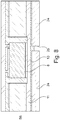
- Figure 1 illustrates a cross-sectional view of a component carrier 1 according to an exemplary embodiment of the invention.
- the component carrier 1 can be shaped as a plate.
- the component carrier 1 can be configured as one of the group consisting of a printed circuit board, a substrate, and an interposer.
- the component carrier 1 can be configured as a laminate-type component carrier.
- the component carrier 1 comprises a stack comprising at least one electrically insulating layer structure 2 and at least one electrically conductive layer structure 3.
- the electrically insulating layer structure 2 can comprise at least one of the group consisting of resin, in particular reinforced or non-reinforced resin, for instance epoxy resin or Bismaleimide-Triazine resin, FR-4, FR-5, cyanate ester, polyphenylene derivate, glass, prepreg material, polyimide, polyamide, liquid crystal polymer, epoxy-based build-up film, polytetrafluoroethylene, a ceramic, and a metal oxide.
- resin in particular reinforced or non-reinforced resin, for instance epoxy resin or Bismaleimide-Triazine resin, FR-4, FR-5, cyanate ester, polyphenylene derivate, glass, prepreg material, polyimide, polyamide, liquid crystal polymer, epoxy-based build-up film, polytetrafluoroethylene, a ceramic, and a metal oxide.
- the at least one electrically conductive layer structure 3 of the component carrier can comprise at least one of the group consisting of copper, aluminum, nickel, silver, gold, palladium, and tungsten, any of the mentioned materials being optionally coated with supra-conductive material such as graphene.
- the component carrier 1 further comprises a heat removing and electrically conductive base structure 4 which can form a kind of lead frame manufactured by PCB technologies, a component 5 which is connected to or arranged in a direct contact with the base structure 4 so as to at least partially protrude from the base structure 4 and so as to be laterally at least partially covered by an electrically insulating material of the stack, and an electrically conductive top structure 6 on or above a top main surface of the component 5.
- a heat removing and electrically conductive base structure 4 which can form a kind of lead frame manufactured by PCB technologies
- a component 5 which is connected to or arranged in a direct contact with the base structure 4 so as to at least partially protrude from the base structure 4 and so as to be laterally at least partially covered by an electrically insulating material of the stack
- an electrically conductive top structure 6 on or above a top main surface of the component 5.
- the component carrier 1 with the above-mentioned configuration exhibits improved heat spreading from the component 5, in particular by the heat removing and electrically conductive base structure 4. High currents flowing vertically through the component carrier 1 can be realized, and an effective thermal management by heat spreading can be achieved.
- the component carrier 1 can be used in applications of about 50 kW, for example in the field of automotive semiconductor applications.
- the base structure 6 is connected to the component 5 for heat spreading, in particular with a heat spreading angle ⁇ of 45°.
- the top structure 6 improves the rigidity of the component carrier 1.
- the top structure 6 comprises a base copper layer 6a which can be a copper foil adhered or laminated on the electrically insulating layer structure 2 above the component 5.
- a copper layer 6b is arranged by electroplating (galvanic copper).
- the base copper layer 6a can be a relative thin copper layer (seed layer).
- the thin copper layer 6a can be applied chemically, electroless or by sputtering.
- a thicker copper layer 6b can be arranged by electroplating (galvanic copper).
- the copper layers 6a, 6b can have a thickness of 50 to 100 ⁇ m, preferable of 70 ⁇ 5 ⁇ m, respectively.
- the component 5 is embedded in the component carrier 1.
- the component 5 can be in particular selected from a group consisting of a power semiconductor component, in particular a power transistor chip, an electronic component, an electrically non-conductive and/or electrically conductive inlay, a heat transfer unit, a light guiding element, an energy harvesting unit, an active electronic component, a passive electronic component, an electronic chip, a storage device, a filter, an integrated circuit, a signal processing component, a power management component, an optoelectronic interface element, a voltage converter, a cryptographic component, a transmitter and/or receiver, an electromechanical transducer, an actuator, a microelectromechanical system, a microprocessor, a capacitor, a resistor, an inductance, an accumulator, a switch, a camera, an antenna, a magnetic element, a further component carrier, and a logic chip.
- a power semiconductor component in particular a power transistor chip, an electronic component, an electrically non-conductive and/or electrically conductive
- the component 5 has two terminals 7 at a top main surface and one terminal 8 at a bottom main surface, wherein the terminal 8 at the bottom main surface is connected to the base structure 4 and the terminals 7 on the top surface are connected to the top structure 6.
- the term "connected" in the present context can include an electrical as well as a thermal link.
- the component 5 is laterally at least partially surrounded by a core 9.
- the core 9 can have a thickness of about 70 to 150 ⁇ m, preferably of 100 ⁇ m ⁇ 5 ⁇ m.
- the base structure 4 can have a thickness, which is measured in a direction perpendicular to a main surface of the component carrier 1, of larger than 100 ⁇ m, in particular larger than 130 ⁇ m; and the top structure 6 can have a thickness of at least 50 ⁇ m, in particular of at least 70 ⁇ m; and the top structure 6 can have a thickness being smaller than a thickness of the base structure 4.
- At least 10% of a height of a sidewall of the component 5 can be contiguously covered with a material of the base structure 4, for example 100 ⁇ m of the sidewall of the component 5 can be contiguously covered with the material of the base structure 4. At least 10% of a height of the sidewall of the component 5 can be contiguously covered with the electrically insulating material of the stack.
- the component carrier 1 further comprises a bottom structure 16a, 16b having a base copper layer 16a which can be a copper foil adhered or laminated on an electrically insulating layer structure 2 below the component 5.
- a copper layer 16b is arranged by electroplating (galvanic copper).
- the base copper layer 16a can be a relativly thin copper layer (seed layer).
- the thin copper layer 16a can be applied chemically, electroless or by sputtering.
- a thicker copper layer 16b can be arranged by electroplating (galvanic copper).
- the copper layers 16a, 16b can have a thickness of 50 to 100 ⁇ m, preferable of 70 ⁇ 5 ⁇ m, respectively.
- the component carrier 1 with the above-mentioned configuration exhibits an improved heat spreading from the component 5, in particular by the heat removing and electrically conductive base structure 4.
- the top structure 6 improves the rigidity of the component carrier 1.
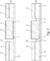
- Figures 2 to 4 illustrate steps of a base concept of manufacturing an inner component carrier 100 according to an exemplary embodiment, where a component 5 is connected to a base structure 4.
- a core 9 made of an insulating material which has a cavity 91.
- the cavity 91 in the core 9 can be provided by mechanically drilling.
- a copper layer 10 is arranged on the core 9.
- the copper layer 10 can have a thickness for example of 70 ⁇ m.
- the copper layer 10 can be a copper foil.
- the core 9 with the copper layer 10 thereon can be a prefabricated board.
- the core 9 might originally have another copper layer (not shown) at the side opposite to the copper layer 10. In the embodiment of Figure 2 , this non-shown other copper layer has been etched away to reduce the thickness of the inner component carrier 100.
- a temporary carrier 14, in particular a sticky tape, is attached to the core 9 at a side opposite to that side where the copper layer 10 is arranged.
- a component 5 is placed on the temporary carrier 14 within the cavity 91.
- the component 5 is a MOSFET having a drain terminal 8 at one side and a source terminal 7 and a gate terminal 7 at the opposite side.
- the component 5 is placed with its source terminal 7 and its gate terminal 7 onto the temporary carrier 14 within the cavity 91 so that the drain terminal 8 is exposed at the top.
- the component 5 is placed face-down in the cavity 91, that means the source terminal 7 and the gate terminal 7 are arranged on the temporary carrier 14.
- the component 5 is fixed by a material of an electrically insulating layer structure 2 in the cavity 91.
- This material of the electrically insulating layer structure 2 can be an adhesive or a molding material.
- the board comprising the core 9 and the copper layer 10 is made of a prepreg material, the board can be laminated by means of pressure and/or heat so that the prepreg material of the core 9 is molten and enters the cavity 91. After curing the prepreg material of the core 9, the component 5 is fixed within the cavity 91.
- the electrically insulating layer structure 2, which is described in step S2 does not cover the entire lateral surfaces of the component 5 so as to reserve a space which can later be filled by a thermal conductive material in order to improve the heat spreading.
- a thin copper layer 15 (seed layer) is applied to the core 9, the electrically insulating layer structure 2 and the terminals 7 of the component 5.
- the thin copper layer 15 can be applied chemically, electroless or by sputtering.
- the thin copper layer 15 can be composed of two horizontally extending regions, wherein a first region (at the left hand side in step S3 of Figure 3 ) is connected to the gate terminal 7 of the component 5, that means a gate line is realized in the thin copper layer 15. A second region (at the right hand side in step S3 of Figure 3 ) of the thin copper layer 15 is connected to the source terminal 7 of the component 5.
- the first and the second regions of the thin copper layer 15 can also be obtained by a conventional patterning process.
- a copper layer 11 is arranged on the copper layer 10 by electroplating (galvanic copper) or by use of a copper foil.
- the copper layer 11 contacts the terminal 8 of the component 5.
- the copper layer 11 fills the space between the component 5 on the one side and the core 9 and the copper layer 10 on the other side.
- the copper layer 11 laterally surrounds the component 5 and contacts the lateral sides of the component 5.
- the base structure 4 is composed of the copper layer 10 and the galvanic copper layer 11.
- the copper foil 10 and the galvanic copper layer 11 can have a thickness of 50 to 100 ⁇ m, preferable of 70 ⁇ 5 ⁇ m, respectively.
- a copper layer 16 is arranged on the thin copper layer 15 by electroplating (galvanic copper).
- the copper layer 16 can have a thickness of 50 to 100 ⁇ m, preferable of 70 ⁇ 5 ⁇ m, respectively.
- an electrically insulating layer structure 2 is applied on the thin copper layer 15.
- Laser vias 31 are formed in this electrically insulating layer structure 2, wherein at least some of the laser vias 31 are connected with the source terminal 7 of the component 5.
- a copper layer 16 is then arranged on the electrically insulating layer structure 2 and in the vias 31, for example by providing a seed layer and subsequently electroplating (galvanic copper).
- the copper layer 16 can also comprise a copper foil.
- the product obtained after steps 4A and 4B, respectively, is the inner component carrier 100 which can be considered as an inner lead frame made by PCB technologies.
- the inner component carrier 100 is composed of the base structure 4, the component 5, and optionally the core 9, the copper layer(s) 10, 11 and the copper layer(s) 15, 16.
- the inner component carrier 100 is formed on panel level, that means the inner component carrier 100 is not formed on wafer level.
- the inner component carrier 100 can have a planar size of about 7 x 7 mm and a height of about 210 ⁇ m.
- the inner component carrier 100 is connected to or integrated in an outer component carrier such as a printed circuit board which is likewise manufactured on panel level.
- the inner component carrier 100 can be embedded into a cavity of the outer component carrier. After that, the cavity can be closed by a molding, adhesive or prepreg material, and further conductive layers can be arranged thereon.
- the inner component carrier 100 and the outer component carrier together form the component carrier 1.
- the inner component carrier 100 for example as a PCB lead frame including the component 5 can be integrated into the outer component carrier such as a lower cost PCB.
- the outer component carrier such as a lower cost PCB.
- a cost saving solution is given by prefabrication of embedded components 5 in an inner PCB lead frame 100 on panel level with utilization of semiconductors as components 5.
- the concept enables to create thick copper lead frames with common embedding technologies and PCB technologies and realizes a fully packaged component 5.
- the manufacturing method can be split into manufacturing a high current PCB, i.e. the inner component carrier 100, and a low cost PCB, i.e. the outer component carrier, with higher routing densities.
- the cost efficiency is improved due to the implementation of a costly lead frame (inner component carrier 100) with the fully packaged component 5 into the cheaper simple PCB (outer component carrier).
- KGP known-good-package
- the copper layers 15, 16 depicted in steps S4A and S4B of Figures 2 to 4 are omitted.
- the cavity is closed by a prepreg or molding material 20 which forms a part of the electrically insulating layer structure 2.
- Vias 21 such as copper-filled laser holes are provided in the molding material 20 to contact the terminals 7 (gate and source) of the component 5.
- the top structure 6 is arranged on the prepreg or molding material 20.
- the top structure 6 can be formed by at least one copper foil such as the copper layer 6a.
- FIG. 5 illustrates a cross-sectional view of a component carrier 1 according to an exemplary embodiment of the invention.
- the embodiment in Figure 5 is similar to the embodiment in Figure 1 except for the following differences.
- the inner component carrier 100 further comprises a sintered layer 17, for example of copper, and a relative thick copper layer 18 which can be a copper foil having a thickness for example of 300 ⁇ m.
- the sintered layer 17 is sintered/ soldered/ diffusion soldered on the galvanic copper layer 11 which has been provided in step S4A or step S4B in Figures 3 and 4 , respectively.
- the sintered layer 17 can have a thickness of about 50 ⁇ m.
- the copper layer 18 is adhered by means of the sintered layer 17.
- the sintered layer 17 can be a patterned sintered layer 17 with openings for a contact to the component 5, for example between the drain terminal 8 of the component 5 and the base structure 4.
- the inner component carrier 100 is composed of the base structure 4, which additionally comprises the sintered layer 17 and the thick copper layer 18, the component 5, and optionally the core 9, the copper layer(s) 10, 11 and the copper layer(s) 15, 16 provided in the base concept depicted in Figures 2 to 4 .
- the core 9 can have a thickness of 70 to 150 ⁇ m, preferably of 100 ⁇ 5 ⁇ m, and the galvanic copper layer 11 can have a thickness of about 50 to 100 ⁇ m, preferably of 70 ⁇ 5 ⁇ m.
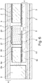
- FIG. 6 illustrates a cross-sectional view of a component carrier 1 according to an exemplary embodiment of the invention.
- the embodiment in Figure 6 is similar to the embodiment in Figure 1 except for the following differences.
- the inner component carrier 100 further comprises an adhesive layer 13 and a relative thick copper layer 18 which can be a copper foil having a thickness for example of 300 ⁇ m.
- the adhesive layer 13 is applied on the galvanic copper layer 11 which has been provided in step S4A or step S4B in Figures 3 and 4 , respectively.
- the adhesive layer 13 can have a thickness of about 10 ⁇ m.
- the copper layer 18 is adhered by means of the adhesive layer 13.
- the adhesive layer 13 can be a patterned adhesive layer 13 with openings for a contact to the component 5, for example between the drain terminal 8 of the component 5 and the base structure 4.
- the inner component carrier 100 is composed of the base structure 4, which in turn comprises the adhesive layer 13 and the thick copper layer 18, the component 5, and optionally the core 9, the copper layer(s) 10, 11 and the copper layer(s) 15, 16 provided in the base concept depicted in Figures 2 to 4 .
- the component 5 in the embodiment of Figure 6 is connected to the base structure 4 so as to completely protrude from the base structure 4 and so as to be laterally completely covered by the electrically insulating material of the stack.
- Figure 7 to 10 illustrate steps of a base concept of manufacturing an inner component carrier 100 according to the exemplary embodiment.
- Reference sign 13 designates an adhesive layer
- reference sign 24 designates a relativly thick copper foil which comprises a mechanically drilled hole 25.
- the adhesive layer 13 is placed between the copper foil 24 and a copper layer, for example a copper layer 11 which is manufactured similar to the copper layer 11 in steps S4A or S4B in Figures 3 and 4 , respectively.
- a state after lamination is shown. A part of adhesive material of the adhesive layer 13 entered the hole 25.
- a desmearing process is carried out where the part of the adhesive material of the adhesive layer 13 is removed from the hole 25 to clean the hole 25.
- the adhesive layer 13 is removed up to the copper layer 11.
- the desmearing process can be carried out by plasma etching.
- a copper layer 26 is filled in the hole 25 to contact the copper layer 11 of the component 5, that means to electrically connect the terminal 8 of the component 5 to the copper foil 24.
- the inner component carrier 100 is completed.
- Figure 11 to 13 illustrate steps of a base concept of manufacturing an inner component carrier 100 according to an exemplary embodiment.
- the inner component carrier 100 in Figure 11 starts out from step S2 in Figure 2 .
- the component carrier 1 is manufactured using the temporary carrier 14 which is temporarily attached to a main surface of the component 5 directed to the top structure 6.
- the temporary carrier 14, which is shown in Figure 2 is removed in Figure 11 .
- an electrically insulating layer structure 2 is applied in place of the temporary carrier 14.
- the electrically insulating layer structure 2 can be made of a molding material or a prepreg material.
- a copper layer 19 is applied on this electrically insulating layer structure 2.
- This copper layer 19 can be a copper foil or a thin copper layer similar to the thin copper layer 15 in Figure 3 , which is applied chemically, electroless or by sputtering.
- the inner component carrier 100 in Figure 11 can start out from a situation which differs from the situation in step S2 in Figure 2 in that the temporary carrier 14 is not arranged on the core 9 but on the copper layer 10, and the component is arranged face-up in the cavity 91, i.e. the drain terminal 8 is adhered to the temporary carrier 14.
- the component carrier 1 is manufactured by use of the temporary carrier 14 which is temporarily attached to a main surface of the component 5 directed to the base structure 4.
- an electrically insulating layer structure 2 is filled in the cavity 91, the temporary carrier 14 is removed and the copper layer 19 is arranged on the electrically insulating layer structure 2 so as to obtain the intermediate inner component carrier as shown in Figure 11 .
- the copper layer 19 and the underlying electrically insulating layer structure 2 are patterned, for example by conventional photoimageable or lithographic processes and laser drilling processes, respectively. As a result, holes such as conical holes are formed in the copper layer 19 and the underlying electrically insulating layer structure 2.
- the holes 22 are filled by an electrically conductive material such as copper so that vias 21 are formed to contact the terminals 7 of the component 5, and a copper layer 16 is arranged on top.
- a copper layer 11 is arranged on the copper layer 10 by electroplating (galvanic copper) or by use of a copper foil.
- the copper layer 11 contacts the terminal 8 of the component 5.
- the copper layer 11 fills the space between the component 5 on the one side and the core 9 and the copper layer 10 on the other side. As a result, the copper layer 11 laterally surrounds the component 5 and contacts the lateral sides of the component 5.
- the base structure 4 is composed of the copper layer 10 and the galvanic copper layer 11.
- a copper layer 16 is arranged on the electrically insulating layer structure 2.
- the copper layer 16 can be a copper foil, or it can be a galvanic copper layer which is applied by electroplating on an underlying seed layer.
- the copper layer 16, the copper layer 10 and the copper layer 11 can each have a thickness between 50 and 100 ⁇ m, preferable of 70 ⁇ 5 ⁇ m.
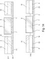
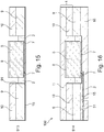
- Figures 14 to 16 illustrate steps of a base concept of manufacturing an inner component carrier 100 according to an exemplary embodiment.
- a core 9 made of an insulating material which has a cavity 91.
- the cavity 91 in the board can be provided by mechanically drilling.
- a copper layer 10 is arranged on the core 9.
- the copper layer 10 can be a copper foil, for example in a thickness of 70 ⁇ m.
- the core 9 with the copper layer 10 thereon can be a prefabricated board.
- the core 9 has another copper layer 23 at the side opposite to the copper layer 10.
- a component 5 is placed on the temporary carrier 14 within the cavity 91.
- the component 5 is a MOSFET having a drain terminal 8 at one side and a source terminal 7 and a gate terminal 7 at the opposite side.
- the component 5 is placed with its source terminal 7 and its gate terminal 7 onto the temporary carrier 14 within the cavity 91 so that the drain terminal 8 is exposed at the top.
- the component 5 is placed face-down in the cavity 91, that means the source terminal 7 and the gate terminal 7 are arranged on the temporary carrier 14.
- the component 5 is fixed by a material of an electrically insulating layer structure 2 in the cavity 91.
- This material of the electrically insulating layer structure 2 can be an adhesive or a molding material.
- the board comprising the core 9 and the copper layer 10 is made of a prepreg material, the board can be laminated by means of pressure and/or heat so that the prepreg material of the core 9 is molten and enters the cavity 91.
- the component 5 After curing the prepreg material of the core 9, the component 5 is fixed within the cavity 91.
- a thin copper layer 15 (seed layer) can be applied to the other copper layer 23, the electrically insulating layer structure 2 and the terminals 7 of the component 5.
- the thin copper layer 15 can be applied chemically, electroless or by sputtering.
- the thin copper layer 15 can be composed of two horizontal regions, wherein a first region (at the left hand side in step S13 of Figure 15 ) is connected to the gate terminal 7 of the component 5, that means a gate line is realized in the thin copper layer 15. A second region (at the right-hand side in step S13 of Figure 15 ) of the thin copper layer 15 is connected to the source terminal 7 of the component 5.
- the first and the second region of the thin copper layer 15 can also be obtained by a conventional patterning process.
- a partial electrically insulating layer structure 2 is applied on the thin copper layer 15 to cover the first region of the thin copper layer 15.
- This electrically insulating layer structure 2 can be provided with vias 31.
- This partial electrically insulating layer structure 2 can be applied by an inkjet process, by screen-printing, by a three-dimensional printing process, etc.
- a copper layer 16 is arranged by electroplating (galvanic copper) on this electrically insulating layer structure 2 and on the second region of the thin copper layer 15.
- the copper layer 16 can optionally be patterned by conventional lithography processes.
- a copper layer 11 is arranged on the copper layer 10 by electroplating (galvanic copper) or by use of a copper foil.
- the copper layer 11 fills the space between the component 5 on the one side and the core 9 and the copper layer 10 on the other side.
- the copper layer 11 laterally surrounds the component 5 and contacts the lateral sides of the component 5.
- the copper layer 11 further contacts the terminal 8 of the component 5.
- the base structure 4 is composed of the copper layer 10 and the galvanic copper layer 11.
Landscapes
- Engineering & Computer Science (AREA)
- Microelectronics & Electronic Packaging (AREA)
- Manufacturing & Machinery (AREA)
- Production Of Multi-Layered Print Wiring Board (AREA)
Abstract
Description
- The invention relates to a component carrier and to a method of manufacturing the same.
- A conventional component carrier comprises a stack having an electrically insulating layer structure and an electrically conductive layer. A component is surface-mounted on or embedded in the stack. Such component carrier can be used in the field of automotive semiconductor applications with high vertical currents. Due to the high vertical currents, heat is generated which may lead to overheating and thus to a failure of the component carrier or the component therein.
- It is an object of the invention to provide a component carrier and a method of manufacturing the same, by which an effective thermal management can be achieved when high vertical currents flow through the component carrier. This object is achieved by the subject matters of the independent claims.
- According to an exemplary embodiment of the invention, a component carrier comprises a stack comprising at least one electrically insulating layer structure and/or at least one electrically conductive layer structure, a heat removing and electrically conductive base structure, a component which is connected to or in a direct contact with the base structure so as to at least partially protrude from the base structure and so as to be laterally at least partially covered by an electrically insulating material of the stack, and an electrically conductive top structure on or above a top main surface of the component.
- According to another exemplary embodiment of the invention, a method of manufacturing a component carrier comprises steps of providing a stack comprising at least one electrically insulating layer structure and/or at least one electrically conductive layer structure, forming a heat removing and electrically conductive base structure, connecting a component to the base structure so that the component at least partially protrudes from the base structure and is covered on its sidewalls at least partially by an electrically insulating material of the stack, and forming an electrically conductive top structure electrically contacting a top main surface of the component.
- In the context of the present application, the term "partially protrude" can mean that a part of the component is embedded in the base structure and the remaining part of the component protrudes from the base structure.
- In the context of the present application, the term "main surface" can refer to a surface of the component where electric terminals are arranged. The term "main surface" can also refer to a surface of component which is perpendicular to a direction in which layers of the stack are arranged or layered one upon the other.
- In the context of the present application, the term "top main surface" can refer to a main surface of the component where a source terminal of the component is arranged. The term "top main surface" can also refer to that main surface of the component which is opposite to a main surface of the component which is embedded in or connected to the base structure. The term "top main surface" can also refer to that main surface of the component which is first inserted into a cavity of the component carrier during a manufacturing process.
- The component carrier with the above-mentioned configuration exhibits improved heat spreading from the component, in particular by the heat removing and electrically conductive base structure. High currents flowing vertically through the component carrier can be realized, and an effective thermal management by heat spreading can be achieved. The component carrier of the present invention can be used in applications of about 50 kW, for example in the field of automotive semiconductor applications.
- The top structure improves the rigidity of the component carrier.
- In the following, further exemplary embodiments of the present invention will be explained.
- In an embodiment, the component is connected to the base structure for heat spreading, in particular at least with a heat spreading angle of 45°. For example, the heat spreading angle can be measured between a vertical lateral side of the component and a line in the base structure, which confines an area of substantial heat transfer. At this line, a temperature gradient measured in the horizontal direction can exhibit a maximum. The angular point of the heat spreading angle can be that point at the lateral side of the component where a transition of the base structure to the electrically insulating material of the stack takes place.
- In an embodiment, the base structure has a thickness of larger than 100 µm, in particular larger than 130 µm; and/or the top structure has a thickness of at least 50 µm, in particular at least 70 µm; and/or the top structure has a thickness being smaller than a thickness of the base structure. The thicknesses can be measured in a direction perpendicular to a main surface of the component carrier. Heat spreading can be further improved by these parameters.
- In an embodiment, the component has at least one terminal at a top main surface and at least one terminal at a bottom main surface, wherein the at least one terminal at the bottom main surface is connected to the base structure and the at least one terminal on the top surface is connected to the top structure. The term "connected" in this context can include an electrical and/or a thermal connection or link.
- In an embodiment, the component is laterally surrounded at least partially by a core to further improve the rigidity.
- In an embodiment, the base structure is composed of a copper foil and a layer of galvanic copper. In an embodiment, the top structure comprises a copper foil. Thereby, the manufacture of the component carrier can be facilitated under less costs.
- In an embodiment, at least 10% of a sidewall of the component is covered with a material of the base structure; and/or at least 10% of a sidewall of the component is covered with the electrically insulating material of the stack. That means, at least 10% of a height of the sidewall of the component can be contiguously covered with a material of the base structure; and/or at least 10% of a height of the sidewall of the component can be contiguously covered with the electrically insulating material of the stack. On the one hand, the thermal resistance is reduced by enlarging the contact interface to the semiconductor, because the side walls are partly plated with copper, for example. On the other hand, the electrically insulating material of the stack covers a part of lateral surfaces of the component so as to prevent electro migration or a disruptive discharge from the terminals of the component.
- In an embodiment, a patterned adhesive or sintered layer is arranged within the base structure and provides an electric and/or thermal contact for the component. Thereby, the manufacture of the component carrier can be facilitated.
- In an embodiment, the component carrier comprises at least one of the following features: the component carrier comprises at least one component being surface mounted on and/or embedded in the component carrier, wherein the at least one component is in particular selected from a group consisting of an electronic component, an electrically non-conductive and/or electrically conductive inlay, a heat transfer unit, a light guiding element, an optical element, a bridge, an energy harvesting unit, an active electronic component, a passive electronic component, an electronic chip, a storage device, a filter, an integrated circuit, a signal processing component, a power management component, an optoelectronic interface element, a voltage converter, a cryptographic component, a transmitter and/or receiver, an electromechanical transducer, an actuator, a microelectromechanical system, a microprocessor, a capacitor, a resistor, an inductance, an accumulator, a switch, a camera, an antenna, a magnetic element, a further component carrier, and a logic chip; wherein at least one of the electrically conductive layer structures of the component carrier comprises at least one of the group consisting of copper, aluminum, nickel, silver, gold, palladium, and tungsten, any of the mentioned materials being optionally coated with supra-conductive material such as graphene; wherein the electrically insulating layer structure comprises at least one of the group consisting of resin, in particular reinforced or non-reinforced resin, for instance epoxy resin or bismaleimide-triazine resin, FR-4, FR-5, cyanate ester, polyphenylene derivate, glass, prepreg material, polyimide, polyamide, liquid crystal polymer, epoxy-based build-up film, polytetrafluoroethylene, a ceramic, and a metal oxide; wherein the component carrier is shaped as a plate; wherein the component carrier is configured as one of the group consisting of a printed circuit board, a substrate, and an interposer; wherein the component carrier is configured as a laminate-type component carrier.
- In an embodiment of the method, an inner component carrier is formed on panel level in the step of connecting the component to the base structure, and the inner component carrier is embedded on panel level in a cavity of an outer component carrier.
- In the context of the present application, the term "panel level" can refer to manufacturing processes such as panel-level-packaging which are carried out on a so called panel. Such panels can have a rectangular format of 300 x 300 mm, 500 x 500 mm. 600 x 600 mm. etc. Manufacturing methods on panel level are usually used in the PCB (printed circuit board) technologies. In contrast to manufacturing methods on panel level, there are manufacturing methods on wafer level which are carried out on a circular (semiconductor) wafer.
- For example, according to the present invention, the inner component carrier as a PCB lead frame with the component can be integrated into a lower cost PCB. With this concept, a cost saving solution is given by prefabrication of embedded components in an inner PCB lead frame on panel level with utilization of semiconductors as components. The concept enables to create thick copper lead frames with common embedding technologies and PCB technologies to form the inner component carrier and realizes a fully packaged component. The manufacturing method can be split into manufacturing a high current PCB (inner component carrier) and a low cost PCB (outer component carrier) with higher routing densities. The cost efficiency is improved due to the implementation of a relative costly lead frame (inner component carrier) with the fully packaged component into the cheaper and simple outer PCB (outer component carrier).
- Furthermore, a known-good-package (KGP) test capability of 100% of the inner component carrier can be achieved before integrating the same into the outer component carrier such as a final PCB build.
- In an embodiment of the method, the component carrier is manufactured by use of a temporary carrier, in particular a sticky tape, being temporarily attached to a main surface of the component relating to the top structure.
- In an embodiment of the method, the component carrier is manufactured by use of a temporary carrier, in particular a sticky tape, being temporarily attached to a main surface of the component corresponding to the base structure.
- In an embodiment of the method, the component carrier is manufactured by a batch process on panel level.
- In the context of the present application, the term "component carrier" may particularly denote any support structure which is capable of accommodating one or more components thereon and/or therein for providing mechanical support and/or electrical connectivity. In other words, a component carrier may be configured as a mechanical and/or electronic carrier for components. In particular, a component carrier may be one of a printed circuit board, an organic interposer, and an IC (integrated circuit) substrate. A component carrier may also be a hybrid board combining different ones of the above mentioned types of component carriers.
- In an embodiment, the component carrier comprises a stack of at least one electrically insulating layer structure and at least one electrically conductive layer structure. For example, the component carrier may be a laminate of the mentioned electrically insulating layer structure(s) and electrically conductive layer structure(s), in particular formed by applying mechanical pressure and/or thermal energy. The mentioned stack may provide a plate-shaped component carrier capable of providing a large mounting surface for further components and being nevertheless very thin and compact. The term "layer structure" may particularly denote a continuous layer, a patterned layer or a plurality of nonconsecutive islands within a common plane.
- In an embodiment, the component carrier is shaped as a plate. This contributes to the compact design, wherein the component carrier nevertheless provides a large basis for mounting components thereon. Furthermore, in particular a naked die as example for an embedded electronic component, can be conveniently embedded, thanks to its small thickness, into a thin plate such as a printed circuit board.
- In an embodiment, the component carrier is configured as one of the group consisting of a printed circuit board, a substrate (in particular an IC substrate), and an interposer.
- In the context of the present application, the term "printed circuit board" (PCB) may particularly denote a plate-shaped component carrier which is formed by laminating several electrically conductive layer structures with several electrically insulating layer structures, for instance by applying pressure and/or by the supply of thermal energy. As preferred materials for PCB technology, the electrically conductive layer structures are made of copper, whereas the electrically insulating layer structures may comprise resin and/or glass fibers, so-called prepreg or FR4 material. The various electrically conductive layer structures may be connected to one another in a desired way by forming through-holes through the laminate, for instance by laser drilling or mechanical drilling, and by filling them with electrically conductive material (in particular copper), thereby forming vias as through-hole connections. Apart from one or more components which may be embedded in a printed circuit board, a printed circuit board is usually configured for accommodating one or more components on one or both opposing surfaces of the plate-shaped printed circuit board. They may be connected to the respective main surface by soldering. A dielectric part of a PCB may be composed of resin with reinforcing fibers (such as glass fibers).
- In the context of the present application, the term "substrate" may particularly denote a small component carrier. A substrate may be a, in relation to a PCB, comparably small component carrier onto which one or more components may be mounted and that may act as a connection medium between one or more chip(s) and a further PCB. For instance, a substrate may have substantially the same size as a component (in particular an electronic component) to be mounted thereon (for instance in case of a Chip Size Package (CSP)). More specifically, a substrate can be understood as a carrier for electrical connections or electrical networks as well as component carrier comparable to a printed circuit board (PCB), however with a considerably higher density of laterally and/or vertically arranged connections. Lateral connections are for example conductive paths, whereas vertical connections may be for example drill holes. These lateral and/or vertical connections are arranged within the substrate and can be used to provide electrical, thermal and/or mechanical connections of housed components or unhoused components (such as bare dies), particularly of IC chips, with a printed circuit board or intermediate printed circuit board. Thus, the term "substrate" also includes "IC substrates". A dielectric part of a substrate may be composed of resin with reinforcing particles (such as reinforcing spheres, in particular glass spheres).
- The substrate or interposer may comprise or consist of at least a layer of glass, silicon (Si) or a photoimageable or dry-etchable organic material like epoxy-based build-up material (such as epoxy-based build-up film) or polymer compounds like polyimide, polybenzoxazole, or benzocyclobutene.
- In an embodiment, the at least one electrically insulating layer structure comprises at least one of the group consisting of resin (such as reinforced or non-reinforced resins, for instance epoxy resin or bismaleimide-triazine resin), cyanate ester, polyphenylene derivate, glass (in particular glass fibers, multilayer glass, glass-like materials), prepreg material (such as FR-4 or FR-5), polyimide, polyamide, liquid crystal polymer (LCP), epoxy-based build-up film, polytetrafluoroethylene (Teflon), a ceramic, and a metal oxide. Reinforcing materials such as webs, fibers or spheres, for example made of glass (multilayer glass) may be used as well. Although prepreg particularly FR4 are usually preferred for rigid PCBs, other materials in particular epoxy-based build-up film or photoimageable dielectric material may be used as well. For high frequency applications, high-frequency materials such as polytetrafluoroethylene, liquid crystal polymer and/or cyanate ester resins, low temperature cofired ceramics (LTCC) or other low, very low or ultra-low DK materials may be implemented in the component carrier as electrically insulating layer structure.
- In an embodiment, the at least one electrically conductive layer structure comprises at least one of the group consisting of copper, aluminum, nickel, silver, gold, palladium, and tungsten. Although copper is usually preferred, other materials or coated versions thereof are possible as well, in particular coated with supra-conductive material such as graphene.
- The at least one component can be selected from a group consisting of an electrically non-conductive inlay, an electrically conductive inlay (such as a metal inlay, preferably comprising copper or aluminum), a heat transfer unit (for example a heat pipe), a light guiding element (for example an optical waveguide or a light conductor connection), an optical element (for instance a lens), an electronic component, or combinations thereof. For example, the component can be an active electronic component, a passive electronic component, an electronic chip, a storage device (for instance a DRAM or another data memory), a filter, an integrated circuit, a signal processing component, a power management component, an optoelectronic interface element, a light emitting diode, a photocoupler, a voltage converter (for example a DC/DC converter or an AC/DC converter), a cryptographic component, a transmitter and/or receiver, an electromechanical transducer, a sensor, an actuator, a microelectromechanical system (MEMS), a microprocessor, a capacitor, a resistor, an inductance, a battery, a switch, a camera, an antenna, a logic chip, and an energy harvesting unit. However, other components may be embedded in the component carrier. For example, a magnetic element can be used as a component. Such a magnetic element may be a permanent magnetic element (such as a ferromagnetic element, an antiferromagnetic element, a multiferroic element or a ferrimagnetic element, for instance a ferrite core) or may be a paramagnetic element. However, the component may also be a substrate, an interposer or a further component carrier, for example in a board-in-board configuration. The component may be surface mounted on the component carrier and/or may be embedded in an interior thereof. Moreover, also other components, in particular those which generate and emit electromagnetic radiation and/or are sensitive with regard to electromagnetic radiation propagating from an environment, may be used as component.
- In an embodiment, the component carrier is a laminate-type component carrier. In such an embodiment, the component carrier is a compound of multiple layer structures which are stacked and connected together by applying a pressing force and/or heat.
- After processing interior layer structures of the component carrier, it is possible to cover (in particular by lamination) one or both opposing main surfaces of the processed layer structures symmetrically or asymmetrically with one or more further electrically insulating layer structures and/or electrically conductive layer structures. In other words, a build-up may be continued until a desired number of layers is obtained
- After having completed formation of a stack of electrically insulating layer structures and electrically conductive layer structures, it is possible to proceed with a surface treatment of the obtained layers structures or component carrier.
- In particular, an electrically insulating solder resist may be applied to one or both opposing main surfaces of the layer stack or component carrier in terms of surface treatment. For instance, it is possible to form such as solder resist on an entire main surface and to subsequently pattern the layer of solder resist so as to expose one or more electrically conductive surface portions which shall be used for electrically coupling the component carrier to an electronic periphery. The surface portions of the component carrier remaining covered with solder resist may be efficiently protected against oxidation or corrosion, in particular surface portions containing copper.
- It is also possible to apply a surface finish selectively to exposed electrically conductive surface portions of the component carrier in terms of surface treatment. Such a surface finish may be an electrically conductive cover material on exposed electrically conductive layer structures (such as pads, conductive tracks, etc., in particular comprising or consisting of copper) on a surface of a component carrier. If such exposed electrically conductive layer structures are left unprotected, then the exposed electrically conductive component carrier material (in particular copper) might oxidize, making the component carrier less reliable. A surface finish may then be formed for instance as an interface between a surface mounted component and the component carrier. The surface finish has the function to protect the exposed electrically conductive layer structures (in particular copper circuitry) and enable a joining process with one or more components, for instance by soldering. Examples for appropriate materials for a surface finish are Organic Solderability Preservative (OSP), Electroless Nickel Immersion Gold (ENIG), gold (in particular Hard Gold), chemical tin, nickel-gold, nickel-palladium, etc.
- The aspects defined above and further aspects of the invention are apparent from the examples of embodiment to be described hereinafter and are explained with reference to these examples of embodiment.
-
Figure 1 illustrates a cross-sectional view of a component carrier according to an exemplary embodiment of the invention. -
Figure 2 illustrates steps of a base concept of manufacturing an inner component carrier according to an exemplary embodiment. -
Figure 3 illustrates steps of the base concept of manufacturing the inner component carrier according to the exemplary embodiment. -
Figure 4 illustrates an alternative step of the base concept of manufacturing the inner component carrier according to the exemplary embodiment. -
Figure 5 illustrates a cross-sectional view of a component carrier according to an exemplary embodiment of the invention. -
Figure 6 illustrates a cross-sectional view of a component carrier according to an exemplary embodiment of the invention. -
Figure 7 illustrates a step of a base concept of manufacturing an inner component carrier according to an exemplary embodiment. -
Figure 8 illustrates a step of the base concept of manufacturing the inner component carrier according to the exemplary embodiment. -
Figure 9 illustrates a step of the base concept of manufacturing the inner component carrier according to the exemplary embodiment. -
Figure 10 illustrates a step of the base concept of manufacturing the inner component carrier according to the exemplary embodiment. -
Figure 11 illustrates a step of a base concept of manufacturing an inner component carrier according to an exemplary embodiment. -
Figure 12 illustrates a step of the base concept of manufacturing the inner component carrier according to the exemplary embodiment. -
Figure 13 illustrates a step of the base concept of manufacturing the inner component carrier according to the exemplary embodiment. -
Figure 14 illustrates steps of a base concept of manufacturing an inner component carrier according to an exemplary embodiment. -
Figure 15 illustrates a step of the base concept of manufacturing the inner component carrier according to the exemplary embodiment. -
Figure 16 illustrates a step of the base concept of manufacturing the inner component carrier according to the exemplary embodiment. - The illustrations in the drawings are schematic. In different drawings, similar or identical elements are provided with the same reference signs.
-
Figure 1 illustrates a cross-sectional view of a component carrier 1 according to an exemplary embodiment of the invention. The component carrier 1 can be shaped as a plate. The component carrier 1 can be configured as one of the group consisting of a printed circuit board, a substrate, and an interposer. The component carrier 1 can be configured as a laminate-type component carrier. - The component carrier 1 comprises a stack comprising at least one electrically insulating
layer structure 2 and at least one electricallyconductive layer structure 3. - The electrically insulating
layer structure 2 can comprise at least one of the group consisting of resin, in particular reinforced or non-reinforced resin, for instance epoxy resin or Bismaleimide-Triazine resin, FR-4, FR-5, cyanate ester, polyphenylene derivate, glass, prepreg material, polyimide, polyamide, liquid crystal polymer, epoxy-based build-up film, polytetrafluoroethylene, a ceramic, and a metal oxide. - The at least one electrically
conductive layer structure 3 of the component carrier can comprise at least one of the group consisting of copper, aluminum, nickel, silver, gold, palladium, and tungsten, any of the mentioned materials being optionally coated with supra-conductive material such as graphene. - The component carrier 1 further comprises a heat removing and electrically
conductive base structure 4 which can form a kind of lead frame manufactured by PCB technologies, acomponent 5 which is connected to or arranged in a direct contact with thebase structure 4 so as to at least partially protrude from thebase structure 4 and so as to be laterally at least partially covered by an electrically insulating material of the stack, and an electrically conductivetop structure 6 on or above a top main surface of thecomponent 5. - The component carrier 1 with the above-mentioned configuration exhibits improved heat spreading from the
component 5, in particular by the heat removing and electricallyconductive base structure 4. High currents flowing vertically through the component carrier 1 can be realized, and an effective thermal management by heat spreading can be achieved. The component carrier 1 can be used in applications of about 50 kW, for example in the field of automotive semiconductor applications. Thebase structure 6 is connected to thecomponent 5 for heat spreading, in particular with a heat spreading angle α of 45°. - The
top structure 6 improves the rigidity of the component carrier 1. Thetop structure 6 comprises abase copper layer 6a which can be a copper foil adhered or laminated on the electrically insulatinglayer structure 2 above thecomponent 5. On thebase copper layer 6a, acopper layer 6b is arranged by electroplating (galvanic copper). Alternatively, thebase copper layer 6a can be a relative thin copper layer (seed layer). Thethin copper layer 6a can be applied chemically, electroless or by sputtering. On thethin copper layer 6a, athicker copper layer 6b can be arranged by electroplating (galvanic copper). The copper layers 6a, 6b can have a thickness of 50 to 100 µm, preferable of 70 ±5 µm, respectively. - The
component 5 is embedded in the component carrier 1. Thecomponent 5 can be in particular selected from a group consisting of a power semiconductor component, in particular a power transistor chip, an electronic component, an electrically non-conductive and/or electrically conductive inlay, a heat transfer unit, a light guiding element, an energy harvesting unit, an active electronic component, a passive electronic component, an electronic chip, a storage device, a filter, an integrated circuit, a signal processing component, a power management component, an optoelectronic interface element, a voltage converter, a cryptographic component, a transmitter and/or receiver, an electromechanical transducer, an actuator, a microelectromechanical system, a microprocessor, a capacitor, a resistor, an inductance, an accumulator, a switch, a camera, an antenna, a magnetic element, a further component carrier, and a logic chip. - The
component 5 has twoterminals 7 at a top main surface and oneterminal 8 at a bottom main surface, wherein theterminal 8 at the bottom main surface is connected to thebase structure 4 and theterminals 7 on the top surface are connected to thetop structure 6. The term "connected" in the present context can include an electrical as well as a thermal link. - The
component 5 is laterally at least partially surrounded by acore 9. Thecore 9 can have a thickness of about 70 to 150 µm, preferably of 100 µm ±5 µm. - The
base structure 4 can have a thickness, which is measured in a direction perpendicular to a main surface of the component carrier 1, of larger than 100 µm, in particular larger than 130 µm; and thetop structure 6 can have a thickness of at least 50 µm, in particular of at least 70 µm; and thetop structure 6 can have a thickness being smaller than a thickness of thebase structure 4. - At least 10% of a height of a sidewall of the
component 5 can be contiguously covered with a material of thebase structure 4, for example 100 µm of the sidewall of thecomponent 5 can be contiguously covered with the material of thebase structure 4. At least 10% of a height of the sidewall of thecomponent 5 can be contiguously covered with the electrically insulating material of the stack. - The component carrier 1 further comprises a
bottom structure base copper layer 16a which can be a copper foil adhered or laminated on an electrically insulatinglayer structure 2 below thecomponent 5. On thebase copper layer 16a, acopper layer 16b is arranged by electroplating (galvanic copper). Alternatively, thebase copper layer 16a can be a relativly thin copper layer (seed layer). Thethin copper layer 16a can be applied chemically, electroless or by sputtering. On thethin copper layer 16a, athicker copper layer 16b can be arranged by electroplating (galvanic copper). The copper layers 16a, 16b can have a thickness of 50 to 100 µm, preferable of 70 ±5 µm, respectively. - In summary, the component carrier 1 with the above-mentioned configuration exhibits an improved heat spreading from the
component 5, in particular by the heat removing and electricallyconductive base structure 4. Thetop structure 6 improves the rigidity of the component carrier 1. -
Figures 2 to 4 illustrate steps of a base concept of manufacturing aninner component carrier 100 according to an exemplary embodiment, where acomponent 5 is connected to abase structure 4. - In a step S1, a
core 9 made of an insulating material is provided, which has acavity 91. Thecavity 91 in thecore 9 can be provided by mechanically drilling. Acopper layer 10 is arranged on thecore 9. Thecopper layer 10 can have a thickness for example of 70 µm. Thecopper layer 10 can be a copper foil. Thecore 9 with thecopper layer 10 thereon can be a prefabricated board. Thecore 9 might originally have another copper layer (not shown) at the side opposite to thecopper layer 10. In the embodiment ofFigure 2 , this non-shown other copper layer has been etched away to reduce the thickness of theinner component carrier 100. - A
temporary carrier 14, in particular a sticky tape, is attached to thecore 9 at a side opposite to that side where thecopper layer 10 is arranged. - A
component 5 is placed on thetemporary carrier 14 within thecavity 91. In the present embodiment, thecomponent 5 is a MOSFET having adrain terminal 8 at one side and asource terminal 7 and agate terminal 7 at the opposite side. Thecomponent 5 is placed with itssource terminal 7 and itsgate terminal 7 onto thetemporary carrier 14 within thecavity 91 so that thedrain terminal 8 is exposed at the top. Thecomponent 5 is placed face-down in thecavity 91, that means thesource terminal 7 and thegate terminal 7 are arranged on thetemporary carrier 14. - In a step S2, the
component 5 is fixed by a material of an electrically insulatinglayer structure 2 in thecavity 91. This material of the electrically insulatinglayer structure 2 can be an adhesive or a molding material. Alternatively, if the board comprising thecore 9 and thecopper layer 10 is made of a prepreg material, the board can be laminated by means of pressure and/or heat so that the prepreg material of thecore 9 is molten and enters thecavity 91. After curing the prepreg material of thecore 9, thecomponent 5 is fixed within thecavity 91. - On the one hand, the electrically insulating
layer structure 2, which is described in step S2, does not cover the entire lateral surfaces of thecomponent 5 so as to reserve a space which can later be filled by a thermal conductive material in order to improve the heat spreading. Alternatively, it is conceivable to remove a part of the electrically insulatinglayer structure 2, which is described in step S2, for example by etching, plasma etching, or a laser process. - The electrically insulating
layer structure 2, which is described in step S2, covers a part of lateral surfaces of thecomponent 5 so as to prevent electro migration or a disruptive discharge from theterminals 7 of thecomponent 5. - In a step S3, the
temporary carrier 14 is removed. In place of thetemporary carrier 14, a thin copper layer 15 (seed layer) is applied to thecore 9, the electrically insulatinglayer structure 2 and theterminals 7 of thecomponent 5. Thethin copper layer 15 can be applied chemically, electroless or by sputtering. - The
thin copper layer 15 can be composed of two horizontally extending regions, wherein a first region (at the left hand side in step S3 ofFigure 3 ) is connected to thegate terminal 7 of thecomponent 5, that means a gate line is realized in thethin copper layer 15. A second region (at the right hand side in step S3 ofFigure 3 ) of thethin copper layer 15 is connected to thesource terminal 7 of thecomponent 5. - The first and the second regions of the
thin copper layer 15 can also be obtained by a conventional patterning process. - In a first alternative in a step S4A in
Figure 3 , acopper layer 11 is arranged on thecopper layer 10 by electroplating (galvanic copper) or by use of a copper foil. Thecopper layer 11 contacts theterminal 8 of thecomponent 5. In addition, thecopper layer 11 fills the space between thecomponent 5 on the one side and thecore 9 and thecopper layer 10 on the other side. As a result, thecopper layer 11 laterally surrounds thecomponent 5 and contacts the lateral sides of thecomponent 5. Thus, thebase structure 4 is composed of thecopper layer 10 and thegalvanic copper layer 11. Thecopper foil 10 and thegalvanic copper layer 11 can have a thickness of 50 to 100 µm, preferable of 70 ±5 µm, respectively. - At the other side of the
inner component carrier 100, acopper layer 16 is arranged on thethin copper layer 15 by electroplating (galvanic copper). Thecopper layer 16 can have a thickness of 50 to 100 µm, preferable of 70 ±5 µm, respectively. - In second alternative in a step S4B in
Figure 4 , which is likewise performed after the step S3 inFigure 3 , an electrically insulatinglayer structure 2 is applied on thethin copper layer 15. Laser vias 31 are formed in this electrically insulatinglayer structure 2, wherein at least some of thelaser vias 31 are connected with thesource terminal 7 of thecomponent 5. Acopper layer 16 is then arranged on the electrically insulatinglayer structure 2 and in thevias 31, for example by providing a seed layer and subsequently electroplating (galvanic copper). Thecopper layer 16 can also comprise a copper foil. - The product obtained after steps 4A and 4B, respectively, is the
inner component carrier 100 which can be considered as an inner lead frame made by PCB technologies. Theinner component carrier 100 is composed of thebase structure 4, thecomponent 5, and optionally thecore 9, the copper layer(s) 10, 11 and the copper layer(s) 15, 16. Theinner component carrier 100 is formed on panel level, that means theinner component carrier 100 is not formed on wafer level. Theinner component carrier 100 can have a planar size of about 7 x 7 mm and a height of about 210 µm. - After having completed the
inner component carrier 100 in the steps S4A and S4B, respectively, theinner component carrier 100 is connected to or integrated in an outer component carrier such as a printed circuit board which is likewise manufactured on panel level. For example, theinner component carrier 100 can be embedded into a cavity of the outer component carrier. After that, the cavity can be closed by a molding, adhesive or prepreg material, and further conductive layers can be arranged thereon. Theinner component carrier 100 and the outer component carrier together form the component carrier 1. - It is possible to manufacture some of the copper layer(s) 10, 11 and of the copper layer(s) 15, 16 not within the base concept depicted in
Figures 2 to 4 but in later steps during manufacturing the outer component carrier. - According to the present invention, the
inner component carrier 100 for example as a PCB lead frame including thecomponent 5 can be integrated into the outer component carrier such as a lower cost PCB. With this concept, a cost saving solution is given by prefabrication of embeddedcomponents 5 in an innerPCB lead frame 100 on panel level with utilization of semiconductors ascomponents 5. The concept enables to create thick copper lead frames with common embedding technologies and PCB technologies and realizes a fully packagedcomponent 5. The manufacturing method can be split into manufacturing a high current PCB, i.e. theinner component carrier 100, and a low cost PCB, i.e. the outer component carrier, with higher routing densities. The cost efficiency is improved due to the implementation of a costly lead frame (inner component carrier 100) with the fully packagedcomponent 5 into the cheaper simple PCB (outer component carrier). - Furthermore, a known-good-package (KGP) test capability of 100% of the
inner component carrier 100 can be achieved before integrating the same into the outer component carrier such as a final PCB build. - In the embodiment of the component carrier 1 in
Figure 1 (as well as inFigures 5 and6 ), the copper layers 15, 16 depicted in steps S4A and S4B ofFigures 2 to 4 are omitted. After having inserted theinner component carrier 100 into the cavity of the outer component carrier, the cavity is closed by a prepreg ormolding material 20 which forms a part of the electrically insulatinglayer structure 2.Vias 21 such as copper-filled laser holes are provided in themolding material 20 to contact the terminals 7 (gate and source) of thecomponent 5. - After that, the
top structure 6 is arranged on the prepreg ormolding material 20. Thetop structure 6 can be formed by at least one copper foil such as thecopper layer 6a. -
Figure 5 illustrates a cross-sectional view of a component carrier 1 according to an exemplary embodiment of the invention. The embodiment inFigure 5 is similar to the embodiment inFigure 1 except for the following differences. Theinner component carrier 100 further comprises a sintered layer 17, for example of copper, and a relativethick copper layer 18 which can be a copper foil having a thickness for example of 300 µm. The sintered layer 17 is sintered/ soldered/ diffusion soldered on thegalvanic copper layer 11 which has been provided in step S4A or step S4B inFigures 3 and4 , respectively. The sintered layer 17 can have a thickness of about 50 µm. Thecopper layer 18 is adhered by means of the sintered layer 17. The sintered layer 17 can be a patterned sintered layer 17 with openings for a contact to thecomponent 5, for example between thedrain terminal 8 of thecomponent 5 and thebase structure 4. - In the embodiment of
Figure 5 , theinner component carrier 100 is composed of thebase structure 4, which additionally comprises the sintered layer 17 and thethick copper layer 18, thecomponent 5, and optionally thecore 9, the copper layer(s) 10, 11 and the copper layer(s) 15, 16 provided in the base concept depicted inFigures 2 to 4 . - The
core 9 can have a thickness of 70 to 150 µm, preferably of 100 ±5 µm, and thegalvanic copper layer 11 can have a thickness of about 50 to 100 µm, preferably of 70 ±5 µm. -
Figure 6 illustrates a cross-sectional view of a component carrier 1 according to an exemplary embodiment of the invention. The embodiment inFigure 6 is similar to the embodiment inFigure 1 except for the following differences. Theinner component carrier 100 further comprises anadhesive layer 13 and a relativethick copper layer 18 which can be a copper foil having a thickness for example of 300 µm. Theadhesive layer 13 is applied on thegalvanic copper layer 11 which has been provided in step S4A or step S4B inFigures 3 and4 , respectively. Theadhesive layer 13 can have a thickness of about 10 µm. Thecopper layer 18 is adhered by means of theadhesive layer 13. - The
adhesive layer 13 can be a patternedadhesive layer 13 with openings for a contact to thecomponent 5, for example between thedrain terminal 8 of thecomponent 5 and thebase structure 4. - In the embodiment of
Figure 6 , theinner component carrier 100 is composed of thebase structure 4, which in turn comprises theadhesive layer 13 and thethick copper layer 18, thecomponent 5, and optionally thecore 9, the copper layer(s) 10, 11 and the copper layer(s) 15, 16 provided in the base concept depicted inFigures 2 to 4 . - Furthermore, the
component 5 in the embodiment ofFigure 6 is connected to thebase structure 4 so as to completely protrude from thebase structure 4 and so as to be laterally completely covered by the electrically insulating material of the stack. -
Figure 7 to 10 illustrate steps of a base concept of manufacturing aninner component carrier 100 according to the exemplary embodiment. - In a step S5, a state before lamination is shown.
Reference sign 13 designates an adhesive layer, andreference sign 24 designates a relativly thick copper foil which comprises a mechanically drilledhole 25. Theadhesive layer 13 is placed between thecopper foil 24 and a copper layer, for example acopper layer 11 which is manufactured similar to thecopper layer 11 in steps S4A or S4B inFigures 3 and4 , respectively. - In a step S6, a state after lamination is shown. A part of adhesive material of the
adhesive layer 13 entered thehole 25. - In a step S7, a desmearing process is carried out where the part of the adhesive material of the
adhesive layer 13 is removed from thehole 25 to clean thehole 25. Theadhesive layer 13 is removed up to thecopper layer 11. The desmearing process can be carried out by plasma etching. - In a step S8, a
copper layer 26 is filled in thehole 25 to contact thecopper layer 11 of thecomponent 5, that means to electrically connect theterminal 8 of thecomponent 5 to thecopper foil 24. At the end, theinner component carrier 100 is completed. -
Figure 11 to 13 illustrate steps of a base concept of manufacturing aninner component carrier 100 according to an exemplary embodiment. - The
inner component carrier 100 inFigure 11 starts out from step S2 inFigure 2 . In this case, the component carrier 1 is manufactured using thetemporary carrier 14 which is temporarily attached to a main surface of thecomponent 5 directed to thetop structure 6. Thetemporary carrier 14, which is shown inFigure 2 , is removed inFigure 11 . In place of thetemporary carrier 14, an electrically insulatinglayer structure 2 is applied in place of thetemporary carrier 14. The electrically insulatinglayer structure 2 can be made of a molding material or a prepreg material. Acopper layer 19 is applied on this electrically insulatinglayer structure 2. Thiscopper layer 19 can be a copper foil or a thin copper layer similar to thethin copper layer 15 inFigure 3 , which is applied chemically, electroless or by sputtering. - Alternatively, the
inner component carrier 100 inFigure 11 can start out from a situation which differs from the situation in step S2 inFigure 2 in that thetemporary carrier 14 is not arranged on thecore 9 but on thecopper layer 10, and the component is arranged face-up in thecavity 91, i.e. thedrain terminal 8 is adhered to thetemporary carrier 14. In this case, the component carrier 1 is manufactured by use of thetemporary carrier 14 which is temporarily attached to a main surface of thecomponent 5 directed to thebase structure 4. - After that, an electrically insulating
layer structure 2 is filled in thecavity 91, thetemporary carrier 14 is removed and thecopper layer 19 is arranged on the electrically insulatinglayer structure 2 so as to obtain the intermediate inner component carrier as shown inFigure 11 . - In
Figure 12 , thecopper layer 19 and the underlying electrically insulatinglayer structure 2 are patterned, for example by conventional photoimageable or lithographic processes and laser drilling processes, respectively. As a result, holes such as conical holes are formed in thecopper layer 19 and the underlying electrically insulatinglayer structure 2. - It is possible to perform a laser ablation process in order to remove a part of the electrically insulating
layer structure 2 around thecomponent 5. - In
Figure 13 , theholes 22 are filled by an electrically conductive material such as copper so thatvias 21 are formed to contact theterminals 7 of thecomponent 5, and acopper layer 16 is arranged on top. - A
copper layer 11 is arranged on thecopper layer 10 by electroplating (galvanic copper) or by use of a copper foil. Thecopper layer 11 contacts theterminal 8 of thecomponent 5. In addition, thecopper layer 11 fills the space between thecomponent 5 on the one side and thecore 9 and thecopper layer 10 on the other side. As a result, thecopper layer 11 laterally surrounds thecomponent 5 and contacts the lateral sides of thecomponent 5. - Thus, the
base structure 4 is composed of thecopper layer 10 and thegalvanic copper layer 11. - A
copper layer 16 is arranged on the electrically insulatinglayer structure 2. Thecopper layer 16 can be a copper foil, or it can be a galvanic copper layer which is applied by electroplating on an underlying seed layer. - For example, the
copper layer 16, thecopper layer 10 and thecopper layer 11 can each have a thickness between 50 and 100 µm, preferable of 70 ±5 µm. -
Figures 14 to 16 illustrate steps of a base concept of manufacturing aninner component carrier 100 according to an exemplary embodiment. - In a step S11, a
core 9 made of an insulating material is provided, which has acavity 91. Thecavity 91 in the board can be provided by mechanically drilling. Acopper layer 10 is arranged on thecore 9. Thecopper layer 10 can be a copper foil, for example in a thickness of 70 µm. Thecore 9 with thecopper layer 10 thereon can be a prefabricated board. Thecore 9 has anothercopper layer 23 at the side opposite to thecopper layer 10. - A
temporary carrier 14, in particular a sticky tape, is attached to theother copper layer 23. Acomponent 5 is placed on thetemporary carrier 14 within thecavity 91. In the present embodiment, thecomponent 5 is a MOSFET having adrain terminal 8 at one side and asource terminal 7 and agate terminal 7 at the opposite side. Thecomponent 5 is placed with itssource terminal 7 and itsgate terminal 7 onto thetemporary carrier 14 within thecavity 91 so that thedrain terminal 8 is exposed at the top. Thecomponent 5 is placed face-down in thecavity 91, that means thesource terminal 7 and thegate terminal 7 are arranged on thetemporary carrier 14. - In a step S12, the
component 5 is fixed by a material of an electrically insulatinglayer structure 2 in thecavity 91. This material of the electrically insulatinglayer structure 2 can be an adhesive or a molding material. Alternatively, if the board comprising thecore 9 and thecopper layer 10 is made of a prepreg material, the board can be laminated by means of pressure and/or heat so that the prepreg material of thecore 9 is molten and enters thecavity 91. - After curing the prepreg material of the
core 9, thecomponent 5 is fixed within thecavity 91. - It is possible to perform a laser ablation process in order to remove a part of the electrically insulating
layer structure 2 around thecomponent 5. - In a step S13, the
temporary carrier 14 is removed. In place of thetemporary carrier 14, a thin copper layer 15 (seed layer) can be applied to theother copper layer 23, the electrically insulatinglayer structure 2 and theterminals 7 of thecomponent 5. Thethin copper layer 15 can be applied chemically, electroless or by sputtering. - The
thin copper layer 15 can be composed of two horizontal regions, wherein a first region (at the left hand side in step S13 ofFigure 15 ) is connected to thegate terminal 7 of thecomponent 5, that means a gate line is realized in thethin copper layer 15. A second region (at the right-hand side in step S13 ofFigure 15 ) of thethin copper layer 15 is connected to thesource terminal 7 of thecomponent 5. The first and the second region of thethin copper layer 15 can also be obtained by a conventional patterning process. - In a step S14, a partial electrically insulating
layer structure 2 is applied on thethin copper layer 15 to cover the first region of thethin copper layer 15. This electrically insulatinglayer structure 2 can be provided withvias 31. This partial electrically insulatinglayer structure 2 can be applied by an inkjet process, by screen-printing, by a three-dimensional printing process, etc. - A
copper layer 16 is arranged by electroplating (galvanic copper) on this electrically insulatinglayer structure 2 and on the second region of thethin copper layer 15. Thecopper layer 16 can optionally be patterned by conventional lithography processes. - A
copper layer 11 is arranged on thecopper layer 10 by electroplating (galvanic copper) or by use of a copper foil. In addition, thecopper layer 11 fills the space between thecomponent 5 on the one side and thecore 9 and thecopper layer 10 on the other side. As a result, thecopper layer 11 laterally surrounds thecomponent 5 and contacts the lateral sides of thecomponent 5. Thecopper layer 11 further contacts theterminal 8 of thecomponent 5. - Thus, the
base structure 4 is composed of thecopper layer 10 and thegalvanic copper layer 11. - It should be noted that the term "comprising" does not exclude other elements or steps and the "a" or "an" does not exclude a plurality. Also elements described in association with different embodiments may be combined.
- It should also be noted that reference signs in the claims shall not be construed as limiting the scope of the claims.
- Implementation of the invention is not limited to the preferred embodiments shown in the figures and described above. Instead, a multiplicity of variants are possible which use the solutions shown and the principle according to the invention even in the case of fundamentally different embodiments.
Claims (15)
- A component carrier (1) comprising:a stack comprising at least one electrically insulating layer structure (2) and/or at least one electrically conductive layer structure (3);a heat removing and electrically conductive base structure (4);a component (5) which is connected to the base structure (4) so as to at least partially protrude from the base structure (4) and so as to be laterally at least partially covered by an electrically insulating material of the stack; andan electrically conductive top structure (6) on or above a top main surface of the component (5).
- The component carrier (1) according to the preceding claim, wherein
the component (5) is connected to the base structure (6) for heat spreading, in particular at least with a heat spreading angle (a) of 45°. - The component carrier (1) according to any one of the preceding claims, wherein
the base structure (4) has a thickness of larger than 100 µm, in particular larger than 130 µm; and/or
the top structure (6) has a thickness of at least 50 µm, in particular at least 70 µm; and/or
the top structure (6) has a thickness being smaller than a thickness of the base structure (4). - The component carrier (1) according to any one of the preceding claims, wherein
the component (5) has at least one terminal (7) at a top main surface and at least one terminal (8) at a bottom main surface, wherein the at least one terminal (8) at the bottom main surface is connected to the base structure (4) and the at least one terminal on the top surface (7) is connected to the top structure (6). - The component carrier (1) according to any one of the preceding claims, wherein
the component (5) is laterally surrounded at least partially by a core (9). - The component carrier (1) according to any one of the preceding claims, wherein
the base structure (4) is composed of a copper foil (10) and a layer of galvanic copper (11). - The component carrier (1) according to any one of the preceding claims, wherein
the top structure (6) comprises a copper foil (6a). - The component carrier (1) according to any one of the preceding claims, wherein
at least 10% of a sidewall of the component (5) is covered with a material of the base structure (4); and/or
at least 10% of a sidewall of the component (5) is covered with an electrically insulating material of the stack. - The component carrier (1) according to any one of the preceding claims, wherein
a patterned adhesive or sintered layer (13, 17) is arranged within the base structure (4) and provides an electric and/or thermal contact for the component (5). - The component carrier (1) according to any one of the preceding claims, comprising at least one of the following features:the component carrier (1) comprises at least one component (5) being surface mounted on and/or embedded in the component carrier, wherein the at least one component is in particular selected from a group consisting of an electronic component, an electrically non-conductive and/or electrically conductive inlay, a heat transfer unit, a light guiding element, an optical element, a bridge, an energy harvesting unit, an active electronic component, a passive electronic component, an electronic chip, a storage device, a filter, an integrated circuit, a signal processing component, a power management component, an optoelectronic interface element, a voltage converter, a cryptographic component, a transmitter and/or receiver, an electromechanical transducer, an actuator, a microelectromechanical system, a microprocessor, a capacitor, a resistor, an inductance, an accumulator, a switch, a camera, an antenna, a magnetic element, a further component carrier, and a logic chip;wherein at least one of the electrically conductive layer structures (3) of the component carrier comprises at least one of the group consisting of copper, aluminum, nickel, silver, gold, palladium, and tungsten, any of the mentioned materials being optionally coated with supra-conductive material such as graphene;wherein the electrically insulating layer structure (2) comprises at least one of the group consisting of resin, in particular reinforced or non-reinforced resin, for instance epoxy resin or bismaleimide-triazine resin, FR-4, FR-5, cyanate ester, polyphenylene derivate, glass, prepreg material, polyimide, polyamide, liquid crystal polymer, epoxy-based build-up film, polytetrafluoroethylene, a ceramic, and a metal oxide;wherein the component carrier (1) is shaped as a plate;wherein the component carrier (1) is configured as one of the group consisting of a printed circuit board, a substrate, and an interposer;wherein the component carrier (1) is configured as a laminate-type component carrier.
- A method of manufacturing a component carrier (1), wherein the method comprises:providing a stack comprising at least one electrically insulating layer (2) structure and/or at least one electrically conductive layer structure (3);forming a heat removing and electrically conductive base structure (4);connecting a component (5) to the base structure (4) so that the component (5) at least partially protrudes from the base structure (4) and is covered on its sidewalls at least partially by an electrically insulating material of the stack; andforming an electrically conductive top structure (6) electrically contacting a top main surface of the component (5).
- The method according to the preceding claim, wherein
an inner component carrier (100) is formed on panel level in the step of connecting the component (5) to the base structure (4), and the inner component carrier (100) is embedded on panel level in a cavity of an outer component carrier. - The method according to any one of the preceding claims 11 and 12, wherein
the component carrier (1) is manufactured using a temporary carrier (14) which is temporarily attached to a main surface of the component (5) directed to the top structure (6). - The method according to any one of the preceding claims 11 to 13, wherein
the component carrier (1) is manufactured by use of a temporary carrier which is temporarily attached to a main surface of the component (5) directed to the base structure (4). - The method according to any one of the preceding claims 11 to 14, wherein
the component carrier (1) is manufactured by a batch process on panel level.
Priority Applications (3)
| Application Number | Priority Date | Filing Date | Title |
|---|---|---|---|
| EP19203022.9A EP3809805B1 (en) | 2019-10-14 | 2019-10-14 | Component carrier and method of manufacturing the same |
| US16/948,937 US11324122B2 (en) | 2019-10-14 | 2020-10-06 | Component carrier and method of manufacturing the same |
| CN202011092747.6A CN112736039B (en) | 2019-10-14 | 2020-10-13 | Component carrier and method for producing a component carrier |
Applications Claiming Priority (1)
| Application Number | Priority Date | Filing Date | Title |
|---|---|---|---|
| EP19203022.9A EP3809805B1 (en) | 2019-10-14 | 2019-10-14 | Component carrier and method of manufacturing the same |
Publications (2)
| Publication Number | Publication Date |
|---|---|
| EP3809805A1 true EP3809805A1 (en) | 2021-04-21 |
| EP3809805B1 EP3809805B1 (en) | 2026-03-04 |
Family
ID=68289816
Family Applications (1)
| Application Number | Title | Priority Date | Filing Date |
|---|---|---|---|
| EP19203022.9A Active EP3809805B1 (en) | 2019-10-14 | 2019-10-14 | Component carrier and method of manufacturing the same |
Country Status (3)
| Country | Link |
|---|---|
| US (1) | US11324122B2 (en) |
| EP (1) | EP3809805B1 (en) |
| CN (1) | CN112736039B (en) |
Families Citing this family (5)
| Publication number | Priority date | Publication date | Assignee | Title |
|---|---|---|---|---|
| EP3557608A1 (en) * | 2018-04-19 | 2019-10-23 | AT & S Austria Technologie & Systemtechnik Aktiengesellschaft | Packaged integrated circuit with interposing functionality and method for manufacturing such a packaged integrated circuit |
| TWI741395B (en) * | 2019-10-23 | 2021-10-01 | 音賜股份有限公司 | Method for installing electro-acoustic components on PCB and structure of electro-acoustic components |
| DE102021112814A1 (en) | 2021-05-18 | 2022-11-24 | Unimicron Germany GmbH | Process for manufacturing a printed circuit board and printed circuit board with at least one embedded electronic component |
| EP4131638A1 (en) * | 2021-08-03 | 2023-02-08 | AT & S Austria Technologie & Systemtechnik Aktiengesellschaft | Component carrier and method of manufacturing a component carrier |
| TWI887998B (en) * | 2024-02-02 | 2025-06-21 | 先豐通訊股份有限公司 | Circuit board and manufacturing method thereof |
Citations (3)
| Publication number | Priority date | Publication date | Assignee | Title |
|---|---|---|---|---|
| CN102300417B (en) * | 2011-08-10 | 2013-09-11 | 深南电路有限公司 | Electronic component embedded type circuit board and manufacture method thereof |
| DE102015120745A1 (en) * | 2015-11-30 | 2017-06-01 | Infineon Technologies Austria Ag | Chip protection cladding and procedure |
| US20180019178A1 (en) * | 2016-07-12 | 2018-01-18 | Industrial Technology Research Institute | Chip packaging and composite system board |
Family Cites Families (14)
| Publication number | Priority date | Publication date | Assignee | Title |
|---|---|---|---|---|
| US6709898B1 (en) * | 2000-10-04 | 2004-03-23 | Intel Corporation | Die-in-heat spreader microelectronic package |
| JP3894091B2 (en) * | 2002-10-11 | 2007-03-14 | ソニー株式会社 | IC chip built-in multilayer substrate and manufacturing method thereof |
| US7112885B2 (en) * | 2003-07-07 | 2006-09-26 | Board Of Regents, The University Of Texas System | System, method and apparatus for improved electrical-to-optical transmitters disposed within printed circuit boards |
| US7539022B2 (en) * | 2005-10-04 | 2009-05-26 | Phoenix Precision Technology Corporation | Chip embedded packaging structure |
| KR101003585B1 (en) * | 2008-06-25 | 2010-12-22 | 삼성전기주식회사 | Electronic component embedded printed circuit board and manufacturing method |
| JP5397012B2 (en) * | 2009-05-19 | 2014-01-22 | 大日本印刷株式会社 | Component built-in wiring board, method of manufacturing component built-in wiring board |
| TWI400998B (en) * | 2010-08-20 | 2013-07-01 | 南亞電路板股份有限公司 | Printed circuit board and method of manufacturing same |
| US8343808B2 (en) * | 2010-11-22 | 2013-01-01 | Bridge Semiconductor Corporation | Method of making stackable semiconductor assembly with bump/base/flange heat spreader and build-up circuitry |
| DE102010060855A1 (en) * | 2010-11-29 | 2012-05-31 | Schweizer Electronic Ag | Electronic component, method for its production and printed circuit board with electronic component |
| TWI446464B (en) * | 2011-05-20 | 2014-07-21 | 旭德科技股份有限公司 | Package structure and manufacturing method thereof |
| CN102623416B (en) * | 2012-04-24 | 2015-09-02 | 苏州远创达科技有限公司 | A kind of power device of radio frequency power amplification modules is without encapsulating structure and assemble method thereof |
| DE102013102542A1 (en) * | 2013-03-13 | 2014-09-18 | Schweizer Electronic Ag | Electronic component and method for manufacturing an electronic component |
| US9659837B2 (en) * | 2015-01-30 | 2017-05-23 | Semiconductor Components Industries, Llc | Direct bonded copper semiconductor packages and related methods |
| TWI612861B (en) * | 2016-09-02 | 2018-01-21 | 先豐通訊股份有限公司 | Wafer embedded circuit board structure and manufacturing method thereof |
-
2019
- 2019-10-14 EP EP19203022.9A patent/EP3809805B1/en active Active
-
2020
- 2020-10-06 US US16/948,937 patent/US11324122B2/en active Active
- 2020-10-13 CN CN202011092747.6A patent/CN112736039B/en active Active
Patent Citations (3)
| Publication number | Priority date | Publication date | Assignee | Title |
|---|---|---|---|---|
| CN102300417B (en) * | 2011-08-10 | 2013-09-11 | 深南电路有限公司 | Electronic component embedded type circuit board and manufacture method thereof |
| DE102015120745A1 (en) * | 2015-11-30 | 2017-06-01 | Infineon Technologies Austria Ag | Chip protection cladding and procedure |
| US20180019178A1 (en) * | 2016-07-12 | 2018-01-18 | Industrial Technology Research Institute | Chip packaging and composite system board |
Also Published As
| Publication number | Publication date |
|---|---|
| US11324122B2 (en) | 2022-05-03 |
| US20210112666A1 (en) | 2021-04-15 |
| CN112736039A (en) | 2021-04-30 |
| CN112736039B (en) | 2024-07-26 |
| EP3809805B1 (en) | 2026-03-04 |
Similar Documents
| Publication | Publication Date | Title |
|---|---|---|
| EP3547361B1 (en) | Component carrier connected with tilted other component carrier for short electric connection | |
| US11810844B2 (en) | Component carrier and method of manufacturing the same | |
| US11324122B2 (en) | Component carrier and method of manufacturing the same | |
| EP3840041B1 (en) | Component carrier with embedded interposer laterally between electrically conductive structures of stack | |
| EP3675163A1 (en) | Component carrier having a component shielding and method of manufacturing the same | |
| EP3869923B1 (en) | Cooling profile integration for embedded power systems | |
| US11470714B2 (en) | Component carrier with embedded component and horizontally elongated via | |
| EP3621107A1 (en) | Component with dielectric layer for embedding in component carrier | |
| CN113645750A (en) | Component carrier and method for producing the same | |
| EP4068918B1 (en) | Embedding methods for fine-pitch components | |
| US12167529B2 (en) | Heat removal architecture for stack-type component carrier with embedded component | |
| US11058004B2 (en) | Metallic layer as carrier for component embedded in cavity of component carrier | |
| US11551989B2 (en) | Component carrier and method of manufacturing the same | |
| US11882648B2 (en) | Dielectric layer for component carrier with varying material properties | |
| EP3846598A1 (en) | Arrangement with a central carrier and two opposing layer stacks, component carrier and manufacturing method | |
| EP3790365A1 (en) | Component carrier and method of manufacturing the same | |
| US12219701B2 (en) | Component carrier | |
| US20240021440A1 (en) | Component Carrier and Method of Manufacturing the Same | |
| US20250071907A1 (en) | Component Carrier With Embedded Interposer Laterally Between Electrically Conductive Structures of Stack |
Legal Events
| Date | Code | Title | Description |
|---|---|---|---|
| PUAI | Public reference made under article 153(3) epc to a published international application that has entered the european phase |
Free format text: ORIGINAL CODE: 0009012 |
|
| STAA | Information on the status of an ep patent application or granted ep patent |
Free format text: STATUS: THE APPLICATION HAS BEEN PUBLISHED |
|
| AK | Designated contracting states |
Kind code of ref document: A1 Designated state(s): AL AT BE BG CH CY CZ DE DK EE ES FI FR GB GR HR HU IE IS IT LI LT LU LV MC MK MT NL NO PL PT RO RS SE SI SK SM TR |
|
| AX | Request for extension of the european patent |
Extension state: BA ME |
|
| STAA | Information on the status of an ep patent application or granted ep patent |
Free format text: STATUS: REQUEST FOR EXAMINATION WAS MADE |
|
| 17P | Request for examination filed |
Effective date: 20210729 |
|
| RBV | Designated contracting states (corrected) |
Designated state(s): AL AT BE BG CH CY CZ DE DK EE ES FI FR GB GR HR HU IE IS IT LI LT LU LV MC MK MT NL NO PL PT RO RS SE SI SK SM TR |
|
| STAA | Information on the status of an ep patent application or granted ep patent |
Free format text: STATUS: EXAMINATION IS IN PROGRESS |
|
| 17Q | First examination report despatched |
Effective date: 20220829 |
|
| GRAP | Despatch of communication of intention to grant a patent |
Free format text: ORIGINAL CODE: EPIDOSNIGR1 |
|
| STAA | Information on the status of an ep patent application or granted ep patent |
Free format text: STATUS: GRANT OF PATENT IS INTENDED |
|
| RIC1 | Information provided on ipc code assigned before grant |
Ipc: H05K 1/02 20060101AFI20251126BHEP Ipc: H01L 23/538 20060101ALI20251126BHEP Ipc: H05K 3/46 20060101ALI20251126BHEP Ipc: H05K 3/40 20060101ALI20251126BHEP Ipc: H05K 1/18 20060101ALI20251126BHEP Ipc: H01L 23/00 20060101ALI20251126BHEP Ipc: H01L 23/367 20060101ALI20251126BHEP Ipc: H01L 23/492 20060101ALI20251126BHEP Ipc: H05K 3/00 20060101ALN20251126BHEP |
|
| INTG | Intention to grant announced |
Effective date: 20251215 |
|
| GRAS | Grant fee paid |
Free format text: ORIGINAL CODE: EPIDOSNIGR3 |
|
| GRAA | (expected) grant |
Free format text: ORIGINAL CODE: 0009210 |
|
| STAA | Information on the status of an ep patent application or granted ep patent |
Free format text: STATUS: THE PATENT HAS BEEN GRANTED |
|
| AK | Designated contracting states |
Kind code of ref document: B1 Designated state(s): AL AT BE BG CH CY CZ DE DK EE ES FI FR GB GR HR HU IE IS IT LI LT LU LV MC MK MT NL NO PL PT RO RS SE SI SK SM TR |
|
| REG | Reference to a national code |
Ref country code: CH Ref legal event code: F10 Free format text: ST27 STATUS EVENT CODE: U-0-0-F10-F00 (AS PROVIDED BY THE NATIONAL OFFICE) Effective date: 20260304 Ref country code: GB Ref legal event code: FG4D |
|
| REG | Reference to a national code |
Ref country code: DE Ref legal event code: R096 Ref document number: 602019082012 Country of ref document: DE |
|
| REG | Reference to a national code |
Ref country code: IE Ref legal event code: FG4D |
|
| P01 | Opt-out of the competence of the unified patent court (upc) registered |
Free format text: CASE NUMBER: UPC_APP_0009988_3809805/2026 Effective date: 20260316 |