EP3809689A1 - Gimbal and camera control method and apparatus - Google Patents
Gimbal and camera control method and apparatus Download PDFInfo
- Publication number
- EP3809689A1 EP3809689A1 EP19931507.8A EP19931507A EP3809689A1 EP 3809689 A1 EP3809689 A1 EP 3809689A1 EP 19931507 A EP19931507 A EP 19931507A EP 3809689 A1 EP3809689 A1 EP 3809689A1
- Authority
- EP
- European Patent Office
- Prior art keywords
- gimbal
- photographing apparatus
- communication link
- indication signal
- state
- Prior art date
- Legal status (The legal status is an assumption and is not a legal conclusion. Google has not performed a legal analysis and makes no representation as to the accuracy of the status listed.)
- Withdrawn
Links
Images


Classifications
-
- H—ELECTRICITY
- H04—ELECTRIC COMMUNICATION TECHNIQUE
- H04N—PICTORIAL COMMUNICATION, e.g. TELEVISION
- H04N23/00—Cameras or camera modules comprising electronic image sensors; Control thereof
- H04N23/60—Control of cameras or camera modules
- H04N23/66—Remote control of cameras or camera parts, e.g. by remote control devices
-
- G—PHYSICS
- G03—PHOTOGRAPHY; CINEMATOGRAPHY; ANALOGOUS TECHNIQUES USING WAVES OTHER THAN OPTICAL WAVES; ELECTROGRAPHY; HOLOGRAPHY
- G03B—APPARATUS OR ARRANGEMENTS FOR TAKING PHOTOGRAPHS OR FOR PROJECTING OR VIEWING THEM; APPARATUS OR ARRANGEMENTS EMPLOYING ANALOGOUS TECHNIQUES USING WAVES OTHER THAN OPTICAL WAVES; ACCESSORIES THEREFOR
- G03B17/00—Details of cameras or camera bodies; Accessories therefor
- G03B17/56—Accessories
- G03B17/561—Support related camera accessories
-
- H—ELECTRICITY
- H04—ELECTRIC COMMUNICATION TECHNIQUE
- H04N—PICTORIAL COMMUNICATION, e.g. TELEVISION
- H04N23/00—Cameras or camera modules comprising electronic image sensors; Control thereof
- H04N23/50—Constructional details
- H04N23/54—Mounting of pick-up tubes, electronic image sensors, deviation or focusing coils
-
- H—ELECTRICITY
- H04—ELECTRIC COMMUNICATION TECHNIQUE
- H04N—PICTORIAL COMMUNICATION, e.g. TELEVISION
- H04N23/00—Cameras or camera modules comprising electronic image sensors; Control thereof
- H04N23/57—Mechanical or electrical details of cameras or camera modules specially adapted for being embedded in other devices
-
- H—ELECTRICITY
- H04—ELECTRIC COMMUNICATION TECHNIQUE
- H04N—PICTORIAL COMMUNICATION, e.g. TELEVISION
- H04N23/00—Cameras or camera modules comprising electronic image sensors; Control thereof
- H04N23/60—Control of cameras or camera modules
- H04N23/65—Control of camera operation in relation to power supply
-
- H—ELECTRICITY
- H04—ELECTRIC COMMUNICATION TECHNIQUE
- H04N—PICTORIAL COMMUNICATION, e.g. TELEVISION
- H04N23/00—Cameras or camera modules comprising electronic image sensors; Control thereof
- H04N23/60—Control of cameras or camera modules
- H04N23/66—Remote control of cameras or camera parts, e.g. by remote control devices
- H04N23/661—Transmitting camera control signals through networks, e.g. control via the Internet
-
- H—ELECTRICITY
- H04—ELECTRIC COMMUNICATION TECHNIQUE
- H04N—PICTORIAL COMMUNICATION, e.g. TELEVISION
- H04N23/00—Cameras or camera modules comprising electronic image sensors; Control thereof
- H04N23/60—Control of cameras or camera modules
- H04N23/667—Camera operation mode switching, e.g. between still and video, sport and normal or high- and low-resolution modes
-
- H—ELECTRICITY
- H04—ELECTRIC COMMUNICATION TECHNIQUE
- H04N—PICTORIAL COMMUNICATION, e.g. TELEVISION
- H04N23/00—Cameras or camera modules comprising electronic image sensors; Control thereof
- H04N23/60—Control of cameras or camera modules
- H04N23/69—Control of means for changing angle of the field of view, e.g. optical zoom objectives or electronic zooming
-
- H—ELECTRICITY
- H04—ELECTRIC COMMUNICATION TECHNIQUE
- H04N—PICTORIAL COMMUNICATION, e.g. TELEVISION
- H04N23/00—Cameras or camera modules comprising electronic image sensors; Control thereof
- H04N23/60—Control of cameras or camera modules
- H04N23/695—Control of camera direction for changing a field of view, e.g. pan, tilt or based on tracking of objects
-
- G—PHYSICS
- G03—PHOTOGRAPHY; CINEMATOGRAPHY; ANALOGOUS TECHNIQUES USING WAVES OTHER THAN OPTICAL WAVES; ELECTROGRAPHY; HOLOGRAPHY
- G03B—APPARATUS OR ARRANGEMENTS FOR TAKING PHOTOGRAPHS OR FOR PROJECTING OR VIEWING THEM; APPARATUS OR ARRANGEMENTS EMPLOYING ANALOGOUS TECHNIQUES USING WAVES OTHER THAN OPTICAL WAVES; ACCESSORIES THEREFOR
- G03B2206/00—Systems for exchange of information between different pieces of apparatus, e.g. for exchanging trimming information, for photo finishing
Definitions
- the present invention relates to the field of photographing apparatus control, and in particular, to a gimbal, a method and apparatus for controlling a photographing apparatus.
- photographing apparatuses such as single-lens reflex cameras or mirrorless interchangeable-lens cameras to record details of life become more and more popular.
- a user may swing a lot when walking, and images captured with a photographing apparatus during walking are shaky.
- the photographing apparatus is usually equipped with a gimbal to assist the photographing.
- the gimbal is connected to the photographing apparatus by a shutter release or in a wireless manner, so that the gimbal can control the photographing apparatus.
- the photographing apparatus is controlled by a gimbal, it is in a PC connection mode and cannot be autonomously controlled (when the photographing apparatus is in an autonomous control mode, a user can operate the photographing apparatus through a key on a body of the photographing apparatus). Consequently, the user cannot operate a key(s) on the body of the photographing apparatus to review images, check parameters of the photographing apparatus, and the like.
- the shutter release connecting the photographing apparatus and the gimbal needs to be disconnected, or a wireless connection function in the settings (settings of the gimbal or settings of the photographing apparatus) needs to be manually disabled, so that the photographing apparatus returns to the autonomous control mode, and the user can operate the key(s) on the body of the photographing apparatus to review images, check parameters of the photographing apparatus, and the like.
- the foregoing operation is cumbersome, and its user experience is poor.
- the present invention provides a gimbal and a control method and apparatus for a photographing apparatus.
- the present invention is implemented through the following technical solutions:
- a control method for a photographing apparatus is provided.
- the photographing apparatus is mounted on a gimbal.
- the photographing apparatus is controlled by the gimbal.
- the method includes:
- a control apparatus for a photographing apparatus is provided.
- the photographing apparatus is mounted on a gimbal.
- the photographing apparatus is controlled by the gimbal.
- the control apparatus for the photographing apparatus includes:
- a gimbal is provided.
- the gimbal includes:
- the communication link between the gimbal and the photographing apparatus is switched from the active state to the inactive state, so that in a process in which the gimbal is used for controlling the photographing apparatus process, the photographing apparatus can restore to an autonomous control mode without physical plugging or unplugging or manual disabling of a wireless connection function in settings, helping a user operate a key on a body of the photographing apparatus to review, or view a parameter of the photographing apparatus, or the like in a process of controlling the photographing apparatus by using the gimbal, thereby giving favorable operation and control experience to the user.
- a gimbal is usually connected to a photographing apparatus through a shutter release, so that the gimbal can control the photographing apparatus.
- a gimbal may be connected to a photographing apparatus in a wireless communication manner, so that the gimbal can control the photographing apparatus.
- the shutter release needs to be disconnected, or a wireless connection function in the settings needs to be manually disabled, in order to disconnect the communication between the gimbal and the photographing apparatus, so that the photographing apparatus restores to an autonomous control mode, and a user can operate a key(s) on a body of the photographing apparatus for reviewing images, or checking parameters of the photographing apparatus, and the like.
- the operation in this manner is cumbersome, and the user experience is poor.
- a communication link between the gimbal and the photographing apparatus is switched from an active state to an inactive state, so that in a process in which the gimbal is used for controlling the photographing apparatus, the photographing apparatus can restore to the autonomous control mode without physical plugging or unplugging or manual disabling of a wireless connection function in the settings, helping a user operate a key(s) on a body of the photographing apparatus to review images, or check parameters of the photographing apparatus, and the like in a process of controlling the photographing apparatus with the gimbal, thereby providing good operation and control experience to the user.
- a photographing apparatus 100 of an embodiment of the present invention is mounted on a gimbal 200. It should be noted that, in this embodiment of the present invention, the photographing apparatus 100 may be a photographing apparatus that can be independently controlled for photographing such as a camera or a video camera.
- the gimbal 200 includes a carrying part and a shaft assembly.
- the carrying part is configured to carry the photographing apparatus 100.
- the photographing apparatus 100 may be mounted on the carrying part in a detachable connection manner.
- the shaft assembly is configured to secure the carrying part. Posture control of the photographing apparatus 100 may be achieved through the shaft assembly.
- the gimbal 200 may be a two-axis gimbal, and the shaft assembly includes two of a yaw shaft assembly, a pitch shaft assembly, and a roll shaft assembly.
- the gimbal 200 may be a three-axis gimbal, and the shaft assembly includes a yaw shaft assembly, a pitch shaft assembly, and a roll shaft assembly.
- the yaw shaft assembly may include a yaw motor
- the pitch shaft assembly may include a pitch axis arm and a pitch motor
- the roll shaft assembly may include a roll axis arm and a roll motor.
- One end of the roll axis arm is connected to a rotator of the yaw motor, and the other end thereof is connected to a stator of the roll motor.
- One end of the pitch axis arm is connected to a rotator of the roll motor, and the other end thereof is connected to a stator of the pitch motor.
- a rotator of the pitch motor is connected to the carrying part.
- the gimbal 200 in this embodiment may be a handheld gimbal, or may be a non-handheld gimbal.
- the gimbal 200 is a handheld gimbal, the gimbal further includes a handle, and the shaft assembly is mounted on a top portion of the handle.
- the gimbal 200 may support different types of photographing apparatuses. As shown in FIG. 2 , the gimbal 200 may respectively control a photographing apparatus A, a photographing apparatus B, and a photographing apparatus C. It should be noted that, in this embodiment of the present invention, the gimbal 200 can carry one photographing apparatus 100 at a time.
- the gimbal 200 is a handheld gimbal, and a user can control the photographing apparatus 100 by using a handle.
- the gimbal 200 may communicate with an external device.
- the external device can indirectly control the photographing apparatus 100 through the transfer of the gimbal 200.
- the external device may include a remote control, a smart mobile terminal (a mobile phone, a tablet computer, or the like), a liquid crystal display (LCD) terminal, or another smart terminal.
- a smart mobile terminal a mobile phone, a tablet computer, or the like
- LCD liquid crystal display
- the communication link may include at least one of a wired communication link and a wireless communication link.
- the photographing apparatus 100 and the gimbal 200 are connected in a wired manner to implement the communication, for example, by using a shutter release.
- the photographing apparatus 100 and the gimbal 200 are connected in a wireless manner to implement the communication, for example, through Bluetooth, Wi-Fi, or infrared.
- the communication link between the photographing apparatus 100 and the gimbal 200 is in an active state, the photographing apparatus 100 is controlled by the gimbal 200. In this case, the photographing apparatus 100 is in a PC connection mode.
- the function of a key on a body of the photographing apparatus 100 is restricted, and a user cannot control the photographing apparatus 100 by operating the key on the body.
- the photographing apparatus 100 may be autonomously controlled. In this case, the photographing apparatus 100 is in an autonomous control mode.
- the function of the key on the body is not restricted, and a user can control the photographing apparatus 100 by operating the key on the body.
- the gimbal 200 in this embodiment of the present invention may alternatively be replaced with another control apparatus for a photographing apparatus that can carry the photographing apparatus 100 and control the photographing apparatus 100.
- FIG. 3 is a method flowchart of a control method for a photographing apparatus according to an embodiment of the present invention.
- the control method for the photographing apparatus may be performed by a gimbal controller, or an independent controller disposed on the gimbal 200.
- the control method for the photographing apparatus may include the following steps: S301: Detect a first indication signal.
- a first indication signal is sent by an external device, and the external device can communicate with the gimbal 200.
- the external device is provided with a virtual or physical control part. When the control part is triggered, the external control device sends the first indication signal to the gimbal 200.
- the external device is a mobile phone, and the mobile phone is provided with an application (APP) that can communicate with the gimbal 200.
- the APP has a button, and when a user operates the virtual button, the APP generates a first indication signal and sends the first indication signal to the gimbal 200.
- the external device is a mouse that can communicate with the gimbal 200. When at least one of a left button, a right button, and a scroll wheel of the mouse is operated, the mouse generates a first indication signal, and sends the first indication signal to the gimbal 200.
- the gimbal 200 includes a first control part, and the first indication signal is generated when the first control part is triggered.
- the first control part may be one of a key, a button, and a knob.
- the first control part is a key, and when a user presses the first control part, the first control part generates the first indication signal.
- the gimbal 200 is a handheld gimbal, and the first control part is disposed on a handle thereof.
- S302 Switch a communication link between the gimbal 200 and the photographing apparatus 100 from an active state to an inactive state, so that the photographing apparatus 100 can be autonomously controlled.
- the photographing apparatus 100 can be switched from the PC connection mode to the autonomous control mode through a one-key operation by means of operating the external device or the first control part. This operation process is simple, convenient, and quick.
- a port on the gimbal 200 for connection to the photographing apparatus 100 may be set to be an inactive port.
- the port when an enable end of the port is at a high level, the port is an active port; when the enable end of the port is at a low level, the port is an inactive port.
- an input level of the enable end of the port may be lowered to switch the communication link between the gimbal 200 and the photographing apparatus 100 from the active state to the inactive state.
- the communication link between the gimbal 200 and the photographing apparatus 100 may also be switched from the active state to the inactive state in another manner.
- the first indication signal is used for instructing the gimbal 200 to switch from a first state to a second state.
- the first state is a wake-up state
- the second state is a sleep state.
- the first state and the second state may alternatively be other states of the gimbal 200. In this embodiment, that the first state is a wake-up state and the second state is a sleep state is used as an example for description.
- the gimbal 200 includes a main controller central processing unit (CPU), a memory, and an external circuit (such as a signal amplification circuit, a communication circuit, etc.).
- the main controller CPU is electrically coupled to the memory and the external circuit respectively.
- the main controller CPU, the memory, and the external circuit are all in a power-on operation state
- the memory can exchange data with the external circuit
- the gimbal 200 can control the photographing apparatus 100 to perform photographing/video recording, or the like.
- the main controller CPU When the gimbal 200 is in the sleep state, the main controller CPU is in a power-off state, that is, the main controller CPU does not consume power; the memory is in a self-refreshing state; and a non-wake-up part(s) of the external circuit may be powered off, and the gimbal 200 needs to be waked up to control the photographing apparatus 100 to perform photographing/video recording, or the like.
- the wake-up state of the gimbal 200 (that is, the wake-up state when the gimbal 200 enters the sleep state) is saved. Once a hardware event (such as a key press) occurs, the gimbal 200 can immediately restore to the saved wake-up state.
- the photographing apparatus 100 When the gimbal 200 is in the sleep state, if the communication link between the gimbal 200 and the photographing apparatus 100 is still active, the photographing apparatus 100 is prevented from entering the sleep state/being powered off, causing the photographing apparatus 100 to consume power.
- the communication link between the gimbal 200 and the photographing apparatus 100 when the gimbal 200 is switched from the wake-up state to the sleep state, the communication link between the gimbal 200 and the photographing apparatus 100 is switched from the active state to the inactive state, and the photographing apparatus 100 automatically enters the sleep state/is powered off after a certain period of time without control, thereby reducing the power consumption of the photographing apparatus 100.
- the gimbal 200 is provided with a sleep key, and the first indication signal is generated when the sleep key is triggered.
- the first indication signal is generated when the sleep key is triggered.
- the sleep key when the gimbal 200 is in the wake-up state, the photographing apparatus 100 is in the PC connection mode.
- the sleep key When the sleep key is single-clicked, the sleep key generates the first indication signal, to switch the communication link between the gimbal 200 and the photographing apparatus 100 from the active state switch to the inactive state, so that the photographing apparatus 100 is switched from the PC connection mode to the autonomous control mode, and the gimbal 200 is switched from the wake-up state to the sleep state.
- the first indication signal is used for instructing to lock the photographing apparatus 100 to a current operation of the photographing apparatus 100. That is, the first indication signal is a signal for enabling a lock function.
- a user operates the gimbal 200, and the gimbal 200 can generate data, but does not transmit the generated data to the photographing apparatus 100 through the communication link between the gimbal 200 and the photographing apparatus 100.
- the gimbal 200 is locked, so that the photographing apparatus 100 is locked in the PC connection mode, and the photographing apparatus 100 is locked to the current operation.
- the gimbal 200 When the gimbal 200 performs the lock function to lock the photographing apparatus 100 to the current operation of the photographing apparatus 100, if the communication link between the gimbal 200 and the photographing apparatus 100 is still active, the lock may fail due to an operation that accidentally triggers a shutter.
- the communication link between the gimbal 200 and the photographing apparatus 100 is switched from the active state to the inactive state. As a result, even if the shutter of the gimbal 200 is accidentally triggered during locking of the photographing apparatus 100 by the gimbal 200, the photographing apparatus 100 is still locked to the current operation, bringing favorable experience to a user.
- the gimbal 200 is provided with a lock key, and the first indication signal is generated when the lock key is triggered.
- the photographing apparatus 100 is in the PC connection mode.
- the lock key When the lock key is single-clicked, the lock key generates the first indication signal.
- the communication link between the gimbal 200 and the photographing apparatus 100 is switched from the active state to the inactive state, so that the photographing apparatus 100 is locked in the PC connection mode, and the gimbal 200 is locked.
- the current operation includes video recording or photographing.
- the gimbal 200 may be used to lock the photographing apparatus 100 to a video recording operation or a photographing operation.
- the photographing apparatus 100 does not exit the currently locked operation. It may be understood that, the current operation may alternatively be another operation.
- the control method for the photographing apparatus further includes: when the first indication signal is detected, prohibiting the photographing apparatus 100 from performing an operation other than the current operation, so as to ensure that the photographing apparatus 100 is locked to the current operation.
- the another operation may include an operation such as parameter setting/viewing or video/picture reviewing other than video recording and photographing.
- the control method for the photographing apparatus further includes: saving current state information of the photographing apparatus 100, to help the gimbal 200 restore state information of the photographing apparatus 100 to the saved current state information after the current lock of the photographing apparatus 100 is released.
- the current state information may include a photographing mode, a video recording mode, or the like of the gimbal 200.
- the communication links between the gimbal 200 and the photographing apparatus 100 include a first communication link and a second communication link.
- the first indication signal is used for instructing to switch the communication link between the gimbal 200 and the photographing apparatus 100 from the first communication link to the second communication link.
- the first communication link is one of a wired communication link and a wireless communication link
- the second communication link is the other one of the wired communication link and the wireless communication link.
- the first communication link and the second communication link are both wireless communication links.
- the first communication link is a Wi-Fi link
- the second communication link is a Bluetooth link.
- the gimbal 200 is connected to the photographing apparatus 100 through a shutter release.
- an APP requests to connect to the Wi-Fi of the photographing apparatus 100 (that is, the first indication signal)
- the communication link between the gimbal 200 and the photographing apparatus 100 is switched from the active state to the inactive state, so that the photographing apparatus 100 is switched from the PC connection mode to the autonomous control mode.
- the first communication link is a wired communication link
- the second communication link is a wireless communication link
- the control method for the photographing apparatus in this embodiment further includes: connecting the photographing apparatus 100 and an external device through the wireless communication link, that is, directly connecting the photographing apparatus 100 and the external device through the wireless communication link, thereby helping the photographing apparatus 100 transmit an image/a video to the external device.
- the connecting the photographing apparatus 100 and an external device through the wireless communication link may include the following two operating steps:
- Connecting to the external device through the built-in Wi-Fi of the photographing apparatus 100 can accelerate data transmission between the photographing apparatus 100 and the external device.
- the first communication link is a wireless communication link
- the second communication link is a wired communication link
- a connection line of the wired connection such as a shutter release, needs to be disconnected, and then the gimbal 200 is connected to the photographing apparatus 100 again through Wi-Fi, Bluetooth, infrared, or another wireless connection manner.
- a wireless connection function corresponding to the current wireless communication link in the settings needs to be manually disabled, thus the current wireless communication link between the gimbal 200 and the photographing apparatus 100 is disconnected, and then the shutter release is manually connected again to the gimbal 200 and the photographing apparatus 100, or a wireless connection function corresponding to another wireless communication link in the settings is manually enabled, so that the gimbal 200 and the photographing apparatus 100 switches from the current wireless communication link to a wired communication link or a different wireless communication link.
- the foregoing switching process is relatively complex, and the existing communication link between the gimbal 200 and the photographing apparatus 100 cannot be automatically switched.
- the communication link between the gimbal 200 and the photographing apparatus 100 is switched from the active state to the inactive state, and the communication link between the gimbal 200 and the photographing apparatus 100 can be switched without physical plugging or unplugging, or manual disabling of the wireless connection function in settings, making the switching of the communication link between the gimbal 200 and the photographing apparatus 100 easier and quicker.
- the control method for the photographing apparatus further includes: when the first indication signal is detected, unloading a drive of the photographing apparatus 100 and a drive of the gimbal 200, so that the gimbal 200 is disconnected from the photographing apparatus 100.
- a software connection between the gimbal 200 and the photographing apparatus 100 can be unloaded, thereby ensuring that the gimbal 200 is fully disconnected from the photographing apparatus 100.
- the control method for the photographing apparatus further includes: resetting the photographing apparatus 100 to preset state information.
- the preset state information is the state information of the photographing apparatus 100 that is obtained before least time the gimbal 200 loads the photographing apparatus 100.
- the preset state information may be state information of the photographing apparatus 100 that is often used by a user, thereby helping the user operate the photographing apparatus 100.
- the preset state information may alternatively be set as other information according to a user's requirement.
- FIG. 7 is a method flowchart of a control method for a photographing apparatus according to another embodiment of the present invention. As shown in FIG. 7 , the control method for the photographing apparatus may further include the following steps: S701: Detect a second indication signal.
- the second indication signal is sent by an external device, and the external device can communicate with the gimbal 200.
- the external device is provided with a virtual or physical control part. When the control part is triggered, the external control device sends the second indication signal to the gimbal 200.
- the external device is a mobile phone, and the mobile phone is provided with an APP that can communicate with the gimbal 200.
- the APP has a button, and when a user operates the virtual button, the APP generates a second indication signal and send the second indication signal to the gimbal 200.
- the external device is a mouse that can communicate with the gimbal 200. When at least one of a left button, a right button, and a scroll wheel of the mouse is operated, the mouse generates a second indication signal, and sends the second indication signal to the gimbal 200.
- the gimbal 200 includes a second control part, and the second indication signal is generated when the second control part is triggered.
- the second control part may be one of a key, a button, and a knob.
- the second control part is a key, and when a user presses the second control part, the second control part generates the second indication signal.
- the gimbal 200 is a handheld gimbal, and the second control part is disposed on a handle.
- the first indication signal and the second indication signal are generated by the same control part.
- a user may single-click the control part to generate the first indication signal; and then single-click the control part again to generate the second indication signal.
- a user may single-click the control portion to generate the first indication signal, and double-click the control portion to generate the second indication signal.
- the first control part and the second control part are a same control part.
- both the first control part and the second control part are a sleep key(s).
- both the first control part and the second control part are a lock key(s).
- the first indication signal and the second indication signal are generated by different control parts.
- the first indication signal is generated when the first control part on the gimbal 200 is triggered
- the second indication signal is generated when the second control part on the gimbal 200 is triggered.
- the first control part and the second control part are control parts independent of each other.
- S702 Switch the communication link between the gimbal 200 and the photographing apparatus 100 from the inactive state to the active state.
- the photographing apparatus 100 After the photographing apparatus 100 is switched from the PC connection mode to the autonomous control mode through the one-key operation described above, if the photographing apparatus 100 needs to be restored to the PC connection mode, only the external device or the second control part needs to be operated with. That is, the photographing apparatus 100 is switched from the autonomous control mode to the PC connection mode through the one-key operation.
- the operation process is simple, convenient, and quick.
- the communication link between the gimbal 200 and the photographing apparatus 100 can be switched from the inactive state to the active state. Specifically, an input level of the enable end of the port is raised.
- the communication link between the gimbal and the photographing apparatus may be switched from the inactive state to the active state in another manner.
- the second indication signal is used for instructing the gimbal 200 to switch from a third state to a fourth state.
- the third state is a sleep state
- the fourth state is a wake-up state.
- the sleep key when the sleep key is single-clicked, the sleep key generates a second indication signal to switch the communication link between the gimbal 200 and the photographing apparatus 100 from the inactive state to the active state, so that the photographing apparatus 100 is switched from the autonomous control mode to the PC connection mode, and the gimbal 200 is switched from the sleep state to the wake-up state.
- the third state and the fourth state may alternatively be other states of the gimbal 200.
- the second indication signal is used for instructing to release a currently locked operation of the photographing apparatus 100. That is, the second indication signal is a signal for disabling a lock function.
- the lock key in the case where the lock function of the gimbal 200 is enabled and the photographing apparatus 100 is locked in the PC connection mode, when the lock key is single-clicked, the lock key generates a second indication signal to switch the communication link between the gimbal 200 and the photographing apparatus 100 from the inactive state to the active state, so that the photographing apparatus 100 is switched to a state in which the locking of the PC connection mode is released, and the lock function of the gimbal 200 is disabled.
- the current operation includes video recording or photographing. Certainly, the current operation may alternatively be another operation.
- the control method for the photographing apparatus further includes: when the second indication signal is detected, restoring a function of the photographing apparatus 100 that is prohibited when the gimbal 200 locks the photographing apparatus 100 to the currently locked operation, thereby helping a user use a function of the photographing apparatus 100. Still further, after the detecting of the second indication signal and prior to the restoring of the function of the photographing apparatus 100 that is prohibited when the gimbal 200 locks the photographing apparatus 100 to the currently locked operation, the control method for the photographing apparatus further includes: saving current state information of the photographing apparatus 100.
- the saved current state information of the photographing apparatus 100 may be state information of the photographing apparatus 100 that is often used by the user.
- the photographing apparatus 100 may be set to the saved current state information of the photographing apparatus 100, for easy use by the user.
- the control method for the photographing apparatus when the second indication signal is used for instructing the gimbal 200 to switch from the third state to the fourth state, the control method for the photographing apparatus further includes: when the second indication signal is detected, initializing the photographing apparatus 100, so that a communication connection between the gimbal 200 and the photographing apparatus 100 is realized.
- the initializing of the photographing apparatus 100 may include operations such as installing drives of the gimbal 200 and the photographing apparatus 100, and setting a parameter(s) of the photographing apparatus 100.
- the control method for the photographing apparatus further includes: restoring state information of the photographing apparatus 100 to the state information of the photographing apparatus 100 obtained when last time the communication link between the gimbal 200 and the photographing apparatus 100 is switched from the active state to the inactive state.
- restoring state information of the photographing apparatus 100 to the state information of the photographing apparatus 100 obtained when last time the communication link between the gimbal 200 and the photographing apparatus 100 is switched from the active state to the inactive state.
- an embodiment of the present invention further provides a control apparatus for a photographing apparatus.
- the control apparatus for the photographing apparatus includes a storage device(s) and one or more processors.
- the storage device(s) is configured to store a program instruction(s).
- the one or more processors are configured to invoke the program instruction(s) stored in the storage device.
- the one or more processors are configured to individually or collectively perform the following operations: detecting a first indication signal; and switching a communication link between a gimbal 200 and a photographing apparatus 100 from an active state switch to an inactive state, so that the photographing apparatus 100 can be autonomously controlled.
- the processor(s) may implement the control method for the photographing apparatus in the embodiments shown in FIG. 3 to FIG. 7 of the present invention.
- the control apparatus for the photographing apparatus in these embodiments may be described by referring to the control method for the photographing apparatus in the foregoing embodiments.
- the processor(s) in these embodiments may be a gimbal controller, or may be an independent controller disposed on the gimbal 200.
- the storage device(s) may include a volatile memory, such as a random-access memory (RAM); or the storage device may include a non-volatile memory, such as a flash memory, a hard disk drive (HDD), or a solid-state drive (SSD); or the storage device 110 may include a combination of the foregoing types of memories.
- RAM random-access memory
- non-volatile memory such as a flash memory, a hard disk drive (HDD), or a solid-state drive (SSD)
- SSD solid-state drive
- the storage device 110 may include a combination of the foregoing types of memories.
- the processor(s) may be a central processing unit (CPU).
- the processor(s) may alternatively be another type of general purpose processor, a digital signal processor (DSP), an application-specific integrated circuit (ASIC), a field-programmable gate array (FPGA) or another programmable logic device, a discrete gate or transistor logic device, a discrete hardware component, or the like.
- DSP digital signal processor
- ASIC application-specific integrated circuit
- FPGA field-programmable gate array
- the general purpose processor may be a microprocessor, or the processor(s) may be any conventional processor, or the like.
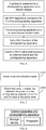
- the gimbal 200 includes a carrying part (not shown), a shaft assembly 210, and a controller 220.
- the carrying part is configured to mount a photographing apparatus 100.
- the shaft assembly 210 is configured to secure the carrying part.
- the controller 220 is in communication connection with the shaft assembly 210. In this embodiment, communication between the gimbal 200 and the photographing apparatus 100 is implemented through the communication connection between the controller 220 and the photographing apparatus 100.
- the controller 220 is configured to perform the following operations: detecting a first indication signal; and switching a communication link between the gimbal 200 and the photographing apparatus 100 from an active state switch to an inactive state, so that the photographing apparatus 100 can be autonomously controlled.
- the controller 220 may implement the control method for the photographing apparatus in the embodiments shown in FIG. 3 to FIG. 7 of the present invention.
- the gimbal 200 in this embodiment may be described by referring to the control method for the photographing apparatus in the foregoing embodiment.
- the controller 220 may be a CPU.
- the controller 220 may alternatively be another general purpose processor, a DSP, an ASIC, an FPGA or another programmable logic device, a discrete gate or transistor logic device, a discrete hardware component, or the like.
- the general purpose processor may be a microprocessor, or the controller 220 may be any conventional processor, or the like.
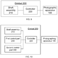
- the gimbal 200 may further include a first control part 230.
- the first control part 230 is electrically connected to the controller 220.
- a first indication signal is generated when the first control part 230 is triggered.
- the first indication signal generated by the first control part 230 can be obtained by the controller 220.
- the gimbal 200 is a handheld gimbal, and the first control part 230 is disposed on a handle of the gimbal 200.
- the first control part 230 may alternatively be disposed at another location on the gimbal 200.
- the first control part 230 may be a key, a button, or a knob, or may be of another type.
- the gimbal 200 may further include a second control part 240.
- the second control part 240 is electrically connected to the controller 220.
- a second indication signal is generated when the second control part 240 is triggered.
- the second indication signal generated by the second control part 240 can be obtained by the controller 220.
- the gimbal 200 is a handheld gimbal, and the second control part 240 is disposed on a handle of the gimbal 200.
- the second control part 240 may alternatively be disposed at another location on the gimbal 200.
- the second control part 240 may be a key, a button, or a knob, or may be of another type.
- the first control part 230 and the second control part 240 may be a same control part, or may be control parts independent from each other.
- an embodiment of the present invention further provides a computer readable storage medium to store a computer program(s).
- the program is executed by a processor(s)
- the steps of the control method for the photographing apparatus in the foregoing embodiments are implemented.
- the computer readable storage medium may be an internal storage unit, such as a hard disk or memory, of the gimbal or the control apparatus for the photographing apparatus in any one of the foregoing embodiments.
- the computer readable storage medium may alternatively be an external storage device of the gimbal or the control apparatus for the photographing apparatus, such as a plug-in hard disk, a smart media card (SMC), an SD card, or a flash card equipped on the device.
- the computer readable storage medium may alternatively include both an internal storage unit and an external storage device of the gimbal or the control apparatus for the photographing apparatus.
- the computer readable storage medium is configured to store the computer program(s) and another program(s) and data that are required by the gimbal or the control apparatus for the photographing apparatus, or may be configured to temporarily store data that is output or to be output.
- the program may be stored in a computer readable storage medium.
- the storage medium may be a magnetic disk, an optical disc, a read-only memory (ROM), a RAM, or the like.
Landscapes
- Engineering & Computer Science (AREA)
- Multimedia (AREA)
- Signal Processing (AREA)
- Physics & Mathematics (AREA)
- General Physics & Mathematics (AREA)
- Studio Devices (AREA)
Abstract
Description
- The present invention relates to the field of photographing apparatus control, and in particular, to a gimbal, a method and apparatus for controlling a photographing apparatus.
- As sensor technology advances and our living standards are greatly improved, photographing apparatuses such as single-lens reflex cameras or mirrorless interchangeable-lens cameras to record details of life become more and more popular. Generally, a user may swing a lot when walking, and images captured with a photographing apparatus during walking are shaky. In order to obtain better image quality, the photographing apparatus is usually equipped with a gimbal to assist the photographing.
- Usually, the gimbal is connected to the photographing apparatus by a shutter release or in a wireless manner, so that the gimbal can control the photographing apparatus. When the photographing apparatus is controlled by a gimbal, it is in a PC connection mode and cannot be autonomously controlled (when the photographing apparatus is in an autonomous control mode, a user can operate the photographing apparatus through a key on a body of the photographing apparatus). Consequently, the user cannot operate a key(s) on the body of the photographing apparatus to review images, check parameters of the photographing apparatus, and the like. In this case, the shutter release connecting the photographing apparatus and the gimbal needs to be disconnected, or a wireless connection function in the settings (settings of the gimbal or settings of the photographing apparatus) needs to be manually disabled, so that the photographing apparatus returns to the autonomous control mode, and the user can operate the key(s) on the body of the photographing apparatus to review images, check parameters of the photographing apparatus, and the like. The foregoing operation is cumbersome, and its user experience is poor.
- The present invention provides a gimbal and a control method and apparatus for a photographing apparatus.
- Specifically, the present invention is implemented through the following technical solutions:
- According to a first aspect of the present invention, a control method for a photographing apparatus is provided. The photographing apparatus is mounted on a gimbal. When a communication link between the photographing apparatus and the gimbal is in an active state, the photographing apparatus is controlled by the gimbal. The method includes:
- detecting a first indication signal; and
- switching the communication link between the gimbal and the photographing apparatus from the active state to an inactive state, so that the photographing apparatus can be controlled autonomously.
- According to a second aspect of the present invention, a control apparatus for a photographing apparatus is provided. The photographing apparatus is mounted on a gimbal. When a communication link between the photographing apparatus and the gimbal is in an active state, the photographing apparatus is controlled by the gimbal. The control apparatus for the photographing apparatus includes:
- a storage device, configured to store a program instruction; and
- one or more processors, configured to invoke the program instruction stored in the storage apparatus, where when the program instruction is executed, the one or more processors are configured to individually or collectively perform the following operations:
- detecting a first indication signal; and
- switching the communication link between the gimbal and the photographing apparatus from the active state to an inactive state, so that the photographing apparatus can be controlled autonomously.
- According to a third aspect of the present invention, a gimbal is provided. The gimbal includes:
- a carrying part, configured to mount a photographing apparatus, where when a communication link between the photographing apparatus and the gimbal is in an active state, the photographing apparatus is controlled by the gimbal;
- a shaft assembly, configured to secure the carrying part; and
- a controller, being in a communication connection with the shaft assembly, where communication between the gimbal and the photographing apparatus is implemented through the communication connection between the controller and the photographing apparatus, and the controller is configured to perform the following operations:
- detecting a first indication signal; and
- switching the communication link between the gimbal and the photographing apparatus from the active state to an inactive state, so that the photographing apparatus can be controlled autonomously.
- It can be learned from the foregoing technical solutions provided in embodiments of the present invention, in the present invention, when the first indication signal is detected, the communication link between the gimbal and the photographing apparatus is switched from the active state to the inactive state, so that in a process in which the gimbal is used for controlling the photographing apparatus process, the photographing apparatus can restore to an autonomous control mode without physical plugging or unplugging or manual disabling of a wireless connection function in settings, helping a user operate a key on a body of the photographing apparatus to review, or view a parameter of the photographing apparatus, or the like in a process of controlling the photographing apparatus by using the gimbal, thereby giving favorable operation and control experience to the user.
- In order to describe the technical solutions in the embodiments of the present invention more clearly, the accompanying drawings for describing the embodiments will be briefly described below. Apparently, the accompanying drawings described below are only some embodiments of the present invention. A person of ordinary skill in the art may further obtain other accompanying drawings based on these accompanying drawings without creative efforts.
-
FIG. 1 is a schematic structural diagram of a control system for a photographing apparatus according to an embodiment of the present invention; -
FIG. 2 is a diagram of an application scenario of a control system for a photographing apparatus according to an embodiment of the present invention; -
FIG. 3 is a method flowchart of a control method for a photographing apparatus according to an embodiment of the present invention; -
FIG. 4 is a method flowchart of a control method for a photographing apparatus according to another embodiment of the present invention; -
FIG. 5 is a method flowchart of a control method for a photographing apparatus according to another embodiment of the present invention; -
FIG. 6 is a method flowchart of a control method for a photographing apparatus according to another embodiment of the present invention; -
FIG. 7 is a method flowchart of a control method for a photographing apparatus according to another embodiment of the present invention; -
FIG. 8 is a structural block diagram of a control apparatus for a photographing apparatus according to an embodiment of the present invention; -
FIG. 9 is a structural block diagram of a gimbal according to an embodiment of the present invention; and -
FIG. 10 is a structural block diagram of a gimbal according to another embodiment of the present invention. - Reference numerals: 100: photographing apparatus; 200: gimbal; 210: shaft assembly; 220: controller; 230: first control part; and 240: second control part.
- Currently, a gimbal is usually connected to a photographing apparatus through a shutter release, so that the gimbal can control the photographing apparatus. Alternatively, a gimbal may be connected to a photographing apparatus in a wireless communication manner, so that the gimbal can control the photographing apparatus. When the photographing apparatus is controlled by the gimbal, the shutter release needs to be disconnected, or a wireless connection function in the settings needs to be manually disabled, in order to disconnect the communication between the gimbal and the photographing apparatus, so that the photographing apparatus restores to an autonomous control mode, and a user can operate a key(s) on a body of the photographing apparatus for reviewing images, or checking parameters of the photographing apparatus, and the like. The operation in this manner is cumbersome, and the user experience is poor.
- Therefore, in the present invention, when a first indication signal is detected, a communication link between the gimbal and the photographing apparatus is switched from an active state to an inactive state, so that in a process in which the gimbal is used for controlling the photographing apparatus, the photographing apparatus can restore to the autonomous control mode without physical plugging or unplugging or manual disabling of a wireless connection function in the settings, helping a user operate a key(s) on a body of the photographing apparatus to review images, or check parameters of the photographing apparatus, and the like in a process of controlling the photographing apparatus with the gimbal, thereby providing good operation and control experience to the user.
- The following clearly and fully describes the technical solutions in the embodiments of the present invention with reference to the accompanying drawings in the embodiments of the present invention. Apparently, the described embodiments are merely some rather than all of the embodiments of the present invention. All other embodiments obtained by a person of ordinary skill in the art based on the embodiments of the present invention without creative efforts shall fall within the scope of protection of the present invention.
- It should be noted that, if there is no conflict, the following embodiments and features in implementations may be combined with each other.
- Referring to
FIG. 1 , a photographing apparatus 100 of an embodiment of the present invention is mounted on agimbal 200. It should be noted that, in this embodiment of the present invention, the photographing apparatus 100 may be a photographing apparatus that can be independently controlled for photographing such as a camera or a video camera. - The
gimbal 200 includes a carrying part and a shaft assembly. The carrying part is configured to carry the photographing apparatus 100. The photographing apparatus 100 may be mounted on the carrying part in a detachable connection manner. The shaft assembly is configured to secure the carrying part. Posture control of the photographing apparatus 100 may be achieved through the shaft assembly. Optionally, thegimbal 200 may be a two-axis gimbal, and the shaft assembly includes two of a yaw shaft assembly, a pitch shaft assembly, and a roll shaft assembly. Optionally, thegimbal 200 may be a three-axis gimbal, and the shaft assembly includes a yaw shaft assembly, a pitch shaft assembly, and a roll shaft assembly. Optionally, the yaw shaft assembly may include a yaw motor, the pitch shaft assembly may include a pitch axis arm and a pitch motor, and the roll shaft assembly may include a roll axis arm and a roll motor. One end of the roll axis arm is connected to a rotator of the yaw motor, and the other end thereof is connected to a stator of the roll motor. One end of the pitch axis arm is connected to a rotator of the roll motor, and the other end thereof is connected to a stator of the pitch motor. A rotator of the pitch motor is connected to the carrying part. To implement a posture change of the photographing apparatus 100, at least one of the following control strategies may be employed: controlling the yaw motor to rotate around a yaw axis, controlling the roll motor to rotate around a roll axis, and controlling the pitch motor to rotate around a pitch axis. In addition, thegimbal 200 in this embodiment may be a handheld gimbal, or may be a non-handheld gimbal. In a feasible embodiment, thegimbal 200 is a handheld gimbal, the gimbal further includes a handle, and the shaft assembly is mounted on a top portion of the handle. - It may be understood that, the
gimbal 200 may support different types of photographing apparatuses. As shown inFIG. 2 , thegimbal 200 may respectively control a photographing apparatus A, a photographing apparatus B, and a photographing apparatus C. It should be noted that, in this embodiment of the present invention, thegimbal 200 can carry one photographing apparatus 100 at a time. - In some embodiments, the
gimbal 200 is a handheld gimbal, and a user can control the photographing apparatus 100 by using a handle. - In some embodiments, the
gimbal 200 may communicate with an external device. The external device can indirectly control the photographing apparatus 100 through the transfer of thegimbal 200. The external device may include a remote control, a smart mobile terminal (a mobile phone, a tablet computer, or the like), a liquid crystal display (LCD) terminal, or another smart terminal. - There is at least one communication link between the photographing apparatus 100 and the
gimbal 200. The communication link may include at least one of a wired communication link and a wireless communication link. Optionally, the photographing apparatus 100 and thegimbal 200 are connected in a wired manner to implement the communication, for example, by using a shutter release. Optionally, the photographing apparatus 100 and thegimbal 200 are connected in a wireless manner to implement the communication, for example, through Bluetooth, Wi-Fi, or infrared. In this embodiment, when the communication link between the photographing apparatus 100 and thegimbal 200 is in an active state, the photographing apparatus 100 is controlled by thegimbal 200. In this case, the photographing apparatus 100 is in a PC connection mode. The function of a key on a body of the photographing apparatus 100 is restricted, and a user cannot control the photographing apparatus 100 by operating the key on the body. When the communication link between the photographing apparatus 100 and thegimbal 200 is in an inactive state, the photographing apparatus 100 may be autonomously controlled. In this case, the photographing apparatus 100 is in an autonomous control mode. The function of the key on the body is not restricted, and a user can control the photographing apparatus 100 by operating the key on the body. - It may be understood that, the
gimbal 200 in this embodiment of the present invention may alternatively be replaced with another control apparatus for a photographing apparatus that can carry the photographing apparatus 100 and control the photographing apparatus 100. -
FIG. 3 is a method flowchart of a control method for a photographing apparatus according to an embodiment of the present invention. The control method for the photographing apparatus may be performed by a gimbal controller, or an independent controller disposed on thegimbal 200. As shown inFIG. 3 , the control method for the photographing apparatus may include the following steps:
S301: Detect a first indication signal. - In some embodiments, a first indication signal is sent by an external device, and the external device can communicate with the
gimbal 200. The external device is provided with a virtual or physical control part. When the control part is triggered, the external control device sends the first indication signal to thegimbal 200. Optionally, the external device is a mobile phone, and the mobile phone is provided with an application (APP) that can communicate with thegimbal 200. The APP has a button, and when a user operates the virtual button, the APP generates a first indication signal and sends the first indication signal to thegimbal 200. Optionally, the external device is a mouse that can communicate with thegimbal 200. When at least one of a left button, a right button, and a scroll wheel of the mouse is operated, the mouse generates a first indication signal, and sends the first indication signal to thegimbal 200. - In some embodiments, the
gimbal 200 includes a first control part, and the first indication signal is generated when the first control part is triggered. The first control part may be one of a key, a button, and a knob. For example, the first control part is a key, and when a user presses the first control part, the first control part generates the first indication signal. Optionally, thegimbal 200 is a handheld gimbal, and the first control part is disposed on a handle thereof. - S302: Switch a communication link between the
gimbal 200 and the photographing apparatus 100 from an active state to an inactive state, so that the photographing apparatus 100 can be autonomously controlled. - In the case where a user uses the
gimbal 200 to control the photographing apparatus 100, when the user needs to operate a key on a body of the photographing apparatus 100 to control the photographing apparatus 100, the photographing apparatus 100 can be switched from the PC connection mode to the autonomous control mode through a one-key operation by means of operating the external device or the first control part. This operation process is simple, convenient, and quick. - A port on the
gimbal 200 for connection to the photographing apparatus 100 may be set to be an inactive port. For example, when an enable end of the port is at a high level, the port is an active port; when the enable end of the port is at a low level, the port is an inactive port. In this case, an input level of the enable end of the port may be lowered to switch the communication link between thegimbal 200 and the photographing apparatus 100 from the active state to the inactive state. Certainly, the communication link between thegimbal 200 and the photographing apparatus 100 may also be switched from the active state to the inactive state in another manner. - In some embodiments, the first indication signal is used for instructing the
gimbal 200 to switch from a first state to a second state. For example, the first state is a wake-up state, and the second state is a sleep state. Certainly, the first state and the second state may alternatively be other states of thegimbal 200. In this embodiment, that the first state is a wake-up state and the second state is a sleep state is used as an example for description. - Optionally, the
gimbal 200 includes a main controller central processing unit (CPU), a memory, and an external circuit (such as a signal amplification circuit, a communication circuit, etc.). The main controller CPU is electrically coupled to the memory and the external circuit respectively. - It should be noted that, when the
gimbal 200 is in the wake-up state, the main controller CPU, the memory, and the external circuit are all in a power-on operation state, the memory can exchange data with the external circuit, and thegimbal 200 can control the photographing apparatus 100 to perform photographing/video recording, or the like. - When the
gimbal 200 is in the sleep state, the main controller CPU is in a power-off state, that is, the main controller CPU does not consume power; the memory is in a self-refreshing state; and a non-wake-up part(s) of the external circuit may be powered off, and thegimbal 200 needs to be waked up to control the photographing apparatus 100 to perform photographing/video recording, or the like. In the sleep state, the wake-up state of the gimbal 200 (that is, the wake-up state when thegimbal 200 enters the sleep state) is saved. Once a hardware event (such as a key press) occurs, thegimbal 200 can immediately restore to the saved wake-up state. - When the
gimbal 200 is in the sleep state, if the communication link between thegimbal 200 and the photographing apparatus 100 is still active, the photographing apparatus 100 is prevented from entering the sleep state/being powered off, causing the photographing apparatus 100 to consume power. In this embodiment, when thegimbal 200 is switched from the wake-up state to the sleep state, the communication link between thegimbal 200 and the photographing apparatus 100 is switched from the active state to the inactive state, and the photographing apparatus 100 automatically enters the sleep state/is powered off after a certain period of time without control, thereby reducing the power consumption of the photographing apparatus 100. - Optionally, the
gimbal 200 is provided with a sleep key, and the first indication signal is generated when the sleep key is triggered. In the embodiment shown inFIG. 4 , when thegimbal 200 is in the wake-up state, the photographing apparatus 100 is in the PC connection mode. When the sleep key is single-clicked, the sleep key generates the first indication signal, to switch the communication link between thegimbal 200 and the photographing apparatus 100 from the active state switch to the inactive state, so that the photographing apparatus 100 is switched from the PC connection mode to the autonomous control mode, and thegimbal 200 is switched from the wake-up state to the sleep state. - In some embodiments, the first indication signal is used for instructing to lock the photographing apparatus 100 to a current operation of the photographing apparatus 100. That is, the first indication signal is a signal for enabling a lock function. In this case, a user operates the
gimbal 200, and thegimbal 200 can generate data, but does not transmit the generated data to the photographing apparatus 100 through the communication link between thegimbal 200 and the photographing apparatus 100. Thegimbal 200 is locked, so that the photographing apparatus 100 is locked in the PC connection mode, and the photographing apparatus 100 is locked to the current operation. - When the
gimbal 200 performs the lock function to lock the photographing apparatus 100 to the current operation of the photographing apparatus 100, if the communication link between thegimbal 200 and the photographing apparatus 100 is still active, the lock may fail due to an operation that accidentally triggers a shutter. In this embodiment, when thegimbal 200 performs the lock function to lock the photographing apparatus 100 to the current operation of the photographing apparatus 100, the communication link between thegimbal 200 and the photographing apparatus 100 is switched from the active state to the inactive state. As a result, even if the shutter of thegimbal 200 is accidentally triggered during locking of the photographing apparatus 100 by thegimbal 200, the photographing apparatus 100 is still locked to the current operation, bringing favorable experience to a user. - Optionally, the
gimbal 200 is provided with a lock key, and the first indication signal is generated when the lock key is triggered. In the embodiment shown inFIG. 5 , when the lock function of thegimbal 200 is turned off, the photographing apparatus 100 is in the PC connection mode. When the lock key is single-clicked, the lock key generates the first indication signal. The communication link between thegimbal 200 and the photographing apparatus 100 is switched from the active state to the inactive state, so that the photographing apparatus 100 is locked in the PC connection mode, and thegimbal 200 is locked. - The current operation includes video recording or photographing. In this embodiment, the
gimbal 200 may be used to lock the photographing apparatus 100 to a video recording operation or a photographing operation. In addition, even if a user accidentally triggers a shutter operation of thegimbal 200, the photographing apparatus 100 does not exit the currently locked operation. It may be understood that, the current operation may alternatively be another operation. - Further, when the first indication signal is used for instructing to lock the photographing apparatus 100 to the current operation of the photographing apparatus 100, the control method for the photographing apparatus further includes: when the first indication signal is detected, prohibiting the photographing apparatus 100 from performing an operation other than the current operation, so as to ensure that the photographing apparatus 100 is locked to the current operation. The another operation may include an operation such as parameter setting/viewing or video/picture reviewing other than video recording and photographing. Still further, after the detecting of the first indication signal, and prior to the prohibiting of the photographing apparatus 100 from performing an operation other than the current operation, the control method for the photographing apparatus further includes: saving current state information of the photographing apparatus 100, to help the
gimbal 200 restore state information of the photographing apparatus 100 to the saved current state information after the current lock of the photographing apparatus 100 is released. The current state information may include a photographing mode, a video recording mode, or the like of thegimbal 200. - In some embodiments, there are at least two communication links between the
gimbal 200 and the photographing apparatus 100, and the communication connection between thegimbal 200 and the photographing apparatus 100 is based on one of the communication links. Optionally, the communication links between thegimbal 200 and the photographing apparatus 100 include a first communication link and a second communication link. The first indication signal is used for instructing to switch the communication link between thegimbal 200 and the photographing apparatus 100 from the first communication link to the second communication link. Optionally, the first communication link is one of a wired communication link and a wireless communication link, and the second communication link is the other one of the wired communication link and the wireless communication link. Optionally, the first communication link and the second communication link are both wireless communication links. For example, the first communication link is a Wi-Fi link, and the second communication link is a Bluetooth link. - In the embodiment shown in
FIG. 6 , thegimbal 200 is connected to the photographing apparatus 100 through a shutter release. When an APP requests to connect to the Wi-Fi of the photographing apparatus 100 (that is, the first indication signal), the communication link between thegimbal 200 and the photographing apparatus 100 is switched from the active state to the inactive state, so that the photographing apparatus 100 is switched from the PC connection mode to the autonomous control mode. - In a feasible embodiment, the first communication link is a wired communication link, and the second communication link is a wireless communication link. Further, the control method for the photographing apparatus in this embodiment further includes: connecting the photographing apparatus 100 and an external device through the wireless communication link, that is, directly connecting the photographing apparatus 100 and the external device through the wireless communication link, thereby helping the photographing apparatus 100 transmit an image/a video to the external device.
- That the wireless communication link is Wi-Fi is used as an example. As shown in
FIG. 6 , the connecting the photographing apparatus 100 and an external device through the wireless communication link may include the following two operating steps: - (1). Set a Wi-Fi function of the photographing apparatus 100. This step can enable built-in Wi-Fi of the photographing apparatus 100.
- (2). Control a Wi-Fi connection between the external device and the photographing apparatus 100.
- Connecting to the external device through the built-in Wi-Fi of the photographing apparatus 100 can accelerate data transmission between the photographing apparatus 100 and the external device.
- In another feasible embodiment, the first communication link is a wireless communication link, and the second communication link is a wired communication link.
- For the existing switch of the communication link between the
gimbal 200 and the photographing apparatus 100, when a wired communication link is being switched to a wireless communication link, a connection line of the wired connection, such as a shutter release, needs to be disconnected, and then thegimbal 200 is connected to the photographing apparatus 100 again through Wi-Fi, Bluetooth, infrared, or another wireless connection manner. When switching from the current wireless communication link to a wired communication link or another wireless communication link, a wireless connection function corresponding to the current wireless communication link in the settings needs to be manually disabled, thus the current wireless communication link between thegimbal 200 and the photographing apparatus 100 is disconnected, and then the shutter release is manually connected again to thegimbal 200 and the photographing apparatus 100, or a wireless connection function corresponding to another wireless communication link in the settings is manually enabled, so that thegimbal 200 and the photographing apparatus 100 switches from the current wireless communication link to a wired communication link or a different wireless communication link. The foregoing switching process is relatively complex, and the existing communication link between thegimbal 200 and the photographing apparatus 100 cannot be automatically switched. In this embodiment, when the first indication signal that is used for instructing to switch the communication link between thegimbal 200 and the photographing apparatus 100 from the first communication link to the second communication link is detected, the communication link between thegimbal 200 and the photographing apparatus 100 is switched from the active state to the inactive state, and the communication link between thegimbal 200 and the photographing apparatus 100 can be switched without physical plugging or unplugging, or manual disabling of the wireless connection function in settings, making the switching of the communication link between thegimbal 200 and the photographing apparatus 100 easier and quicker. - In the case where the first indication signal is generated to instruct the
gimbal 200 to switch from the first state to the second state, or instruct to switch the communication link between thegimbal 200 and the photographing apparatus 100 from the first communication link to the second communication link, the control method for the photographing apparatus further includes: when the first indication signal is detected, unloading a drive of the photographing apparatus 100 and a drive of thegimbal 200, so that thegimbal 200 is disconnected from the photographing apparatus 100. By means of the foregoing operation, a software connection between thegimbal 200 and the photographing apparatus 100 can be unloaded, thereby ensuring that thegimbal 200 is fully disconnected from the photographing apparatus 100. Further, after the detecting of the first indication signal, and prior to the unloading of the drives of the photographing apparatus 100 and thegimbal 200, the control method for the photographing apparatus further includes: resetting the photographing apparatus 100 to preset state information. The preset state information is the state information of the photographing apparatus 100 that is obtained before least time thegimbal 200 loads the photographing apparatus 100. The preset state information may be state information of the photographing apparatus 100 that is often used by a user, thereby helping the user operate the photographing apparatus 100. Certainly, the preset state information may alternatively be set as other information according to a user's requirement. -
FIG. 7 is a method flowchart of a control method for a photographing apparatus according to another embodiment of the present invention. As shown inFIG. 7 , the control method for the photographing apparatus may further include the following steps:
S701: Detect a second indication signal. - In some embodiments, the second indication signal is sent by an external device, and the external device can communicate with the
gimbal 200. The external device is provided with a virtual or physical control part. When the control part is triggered, the external control device sends the second indication signal to thegimbal 200. Optionally, the external device is a mobile phone, and the mobile phone is provided with an APP that can communicate with thegimbal 200. The APP has a button, and when a user operates the virtual button, the APP generates a second indication signal and send the second indication signal to thegimbal 200. Optionally, the external device is a mouse that can communicate with thegimbal 200. When at least one of a left button, a right button, and a scroll wheel of the mouse is operated, the mouse generates a second indication signal, and sends the second indication signal to thegimbal 200. - In some embodiments, the
gimbal 200 includes a second control part, and the second indication signal is generated when the second control part is triggered. The second control part may be one of a key, a button, and a knob. For example, the second control part is a key, and when a user presses the second control part, the second control part generates the second indication signal. Optionally, thegimbal 200 is a handheld gimbal, and the second control part is disposed on a handle. - In some embodiments, the first indication signal and the second indication signal are generated by the same control part. Optionally, a user may single-click the control part to generate the first indication signal; and then single-click the control part again to generate the second indication signal. Optionally, a user may single-click the control portion to generate the first indication signal, and double-click the control portion to generate the second indication signal. Optionally, the first control part and the second control part are a same control part. In the embodiment shown in
FIG. 4 , both the first control part and the second control part are a sleep key(s). In the embodiment shown inFIG. 5 , both the first control part and the second control part are a lock key(s). - In some embodiments, the first indication signal and the second indication signal are generated by different control parts. For example, the first indication signal is generated when the first control part on the
gimbal 200 is triggered, and the second indication signal is generated when the second control part on thegimbal 200 is triggered. The first control part and the second control part are control parts independent of each other. - S702: Switch the communication link between the
gimbal 200 and the photographing apparatus 100 from the inactive state to the active state. - After the photographing apparatus 100 is switched from the PC connection mode to the autonomous control mode through the one-key operation described above, if the photographing apparatus 100 needs to be restored to the PC connection mode, only the external device or the second control part needs to be operated with. That is, the photographing apparatus 100 is switched from the autonomous control mode to the PC connection mode through the one-key operation. Thus, the operation process is simple, convenient, and quick.
- By means of restoring a port on the
gimbal 200 for connection to the photographing apparatus 100 from an inactive port to an active port, the communication link between thegimbal 200 and the photographing apparatus 100 can be switched from the inactive state to the active state. Specifically, an input level of the enable end of the port is raised. Certainly, the communication link between the gimbal and the photographing apparatus may be switched from the inactive state to the active state in another manner. - In some embodiments, the second indication signal is used for instructing the
gimbal 200 to switch from a third state to a fourth state. For example, the third state is a sleep state, and the fourth state is a wake-up state. As shown inFIG. 4 , in the case where thegimbal 200 is in the sleep state and the photographing apparatus 100 is in the autonomous control mode, when the sleep key is single-clicked, the sleep key generates a second indication signal to switch the communication link between thegimbal 200 and the photographing apparatus 100 from the inactive state to the active state, so that the photographing apparatus 100 is switched from the autonomous control mode to the PC connection mode, and thegimbal 200 is switched from the sleep state to the wake-up state. Certainly, the third state and the fourth state may alternatively be other states of thegimbal 200. - In some embodiments, the second indication signal is used for instructing to release a currently locked operation of the photographing apparatus 100. That is, the second indication signal is a signal for disabling a lock function. As shown in
FIG. 5 , in the case where the lock function of thegimbal 200 is enabled and the photographing apparatus 100 is locked in the PC connection mode, when the lock key is single-clicked, the lock key generates a second indication signal to switch the communication link between thegimbal 200 and the photographing apparatus 100 from the inactive state to the active state, so that the photographing apparatus 100 is switched to a state in which the locking of the PC connection mode is released, and the lock function of thegimbal 200 is disabled. The current operation includes video recording or photographing. Certainly, the current operation may alternatively be another operation. - Further, when the second indication signal is used for instructing to release the currently locked operation of the photographing apparatus 100, the control method for the photographing apparatus further includes: when the second indication signal is detected, restoring a function of the photographing apparatus 100 that is prohibited when the
gimbal 200 locks the photographing apparatus 100 to the currently locked operation, thereby helping a user use a function of the photographing apparatus 100. Still further, after the detecting of the second indication signal and prior to the restoring of the function of the photographing apparatus 100 that is prohibited when thegimbal 200 locks the photographing apparatus 100 to the currently locked operation, the control method for the photographing apparatus further includes: saving current state information of the photographing apparatus 100. The saved current state information of the photographing apparatus 100 may be state information of the photographing apparatus 100 that is often used by the user. When the photographing apparatus 100 is locked next time, the photographing apparatus 100 may be set to the saved current state information of the photographing apparatus 100, for easy use by the user. - In some embodiments, when the second indication signal is used for instructing the
gimbal 200 to switch from the third state to the fourth state, the control method for the photographing apparatus further includes: when the second indication signal is detected, initializing the photographing apparatus 100, so that a communication connection between thegimbal 200 and the photographing apparatus 100 is realized. The initializing of the photographing apparatus 100 may include operations such as installing drives of thegimbal 200 and the photographing apparatus 100, and setting a parameter(s) of the photographing apparatus 100. Further, after the initializing of the photographing apparatus 100, the control method for the photographing apparatus further includes: restoring state information of the photographing apparatus 100 to the state information of the photographing apparatus 100 obtained when last time the communication link between thegimbal 200 and the photographing apparatus 100 is switched from the active state to the inactive state. Such a setting can restore the state information of the photographing apparatus 100 to state information of the photographing apparatus 100 that is often used by a user, thereby helping the user use thegimbal 200 to control the photographing apparatus 100. - Corresponding to the control method for the photographing apparatus in the foregoing embodiments, an embodiment of the present invention further provides a control apparatus for a photographing apparatus. As shown in
FIG. 8 , the control apparatus for the photographing apparatus includes a storage device(s) and one or more processors. - The storage device(s) is configured to store a program instruction(s). The one or more processors are configured to invoke the program instruction(s) stored in the storage device. When the program instruction(s) is executed, the one or more processors are configured to individually or collectively perform the following operations: detecting a first indication signal; and switching a communication link between a
gimbal 200 and a photographing apparatus 100 from an active state switch to an inactive state, so that the photographing apparatus 100 can be autonomously controlled. - The processor(s) may implement the control method for the photographing apparatus in the embodiments shown in
FIG. 3 to FIG. 7 of the present invention. The control apparatus for the photographing apparatus in these embodiments may be described by referring to the control method for the photographing apparatus in the foregoing embodiments. - The processor(s) in these embodiments may be a gimbal controller, or may be an independent controller disposed on the
gimbal 200. - The storage device(s) may include a volatile memory, such as a random-access memory (RAM); or the storage device may include a non-volatile memory, such as a flash memory, a hard disk drive (HDD), or a solid-state drive (SSD); or the storage device 110 may include a combination of the foregoing types of memories.
- The processor(s) may be a central processing unit (CPU). The processor(s) may alternatively be another type of general purpose processor, a digital signal processor (DSP), an application-specific integrated circuit (ASIC), a field-programmable gate array (FPGA) or another programmable logic device, a discrete gate or transistor logic device, a discrete hardware component, or the like. The general purpose processor may be a microprocessor, or the processor(s) may be any conventional processor, or the like.
- An embodiment of the present invention further provides a gimbal. Referring to
FIG. 9 , thegimbal 200 includes a carrying part (not shown), ashaft assembly 210, and acontroller 220. The carrying part is configured to mount a photographing apparatus 100. Theshaft assembly 210 is configured to secure the carrying part. Thecontroller 220 is in communication connection with theshaft assembly 210. In this embodiment, communication between thegimbal 200 and the photographing apparatus 100 is implemented through the communication connection between thecontroller 220 and the photographing apparatus 100. - The
controller 220 is configured to perform the following operations: detecting a first indication signal; and switching a communication link between thegimbal 200 and the photographing apparatus 100 from an active state switch to an inactive state, so that the photographing apparatus 100 can be autonomously controlled. - The
controller 220 may implement the control method for the photographing apparatus in the embodiments shown inFIG. 3 to FIG. 7 of the present invention. Thegimbal 200 in this embodiment may be described by referring to the control method for the photographing apparatus in the foregoing embodiment. - The
controller 220 may be a CPU. Thecontroller 220 may alternatively be another general purpose processor, a DSP, an ASIC, an FPGA or another programmable logic device, a discrete gate or transistor logic device, a discrete hardware component, or the like. The general purpose processor may be a microprocessor, or thecontroller 220 may be any conventional processor, or the like. - Referring to
FIG. 10 , thegimbal 200 may further include afirst control part 230. Thefirst control part 230 is electrically connected to thecontroller 220. A first indication signal is generated when thefirst control part 230 is triggered. The first indication signal generated by thefirst control part 230 can be obtained by thecontroller 220. Optionally, thegimbal 200 is a handheld gimbal, and thefirst control part 230 is disposed on a handle of thegimbal 200. Certainly, thefirst control part 230 may alternatively be disposed at another location on thegimbal 200. Thefirst control part 230 may be a key, a button, or a knob, or may be of another type. - Still referring to
FIG. 10 , thegimbal 200 may further include asecond control part 240. Thesecond control part 240 is electrically connected to thecontroller 220. A second indication signal is generated when thesecond control part 240 is triggered. The second indication signal generated by thesecond control part 240 can be obtained by thecontroller 220. Optionally, thegimbal 200 is a handheld gimbal, and thesecond control part 240 is disposed on a handle of thegimbal 200. Certainly, thesecond control part 240 may alternatively be disposed at another location on thegimbal 200. Thesecond control part 240 may be a key, a button, or a knob, or may be of another type. - The
first control part 230 and thesecond control part 240 may be a same control part, or may be control parts independent from each other. - In addition, an embodiment of the present invention further provides a computer readable storage medium to store a computer program(s). When the program is executed by a processor(s), the steps of the control method for the photographing apparatus in the foregoing embodiments are implemented.
- The computer readable storage medium may be an internal storage unit, such as a hard disk or memory, of the gimbal or the control apparatus for the photographing apparatus in any one of the foregoing embodiments. The computer readable storage medium may alternatively be an external storage device of the gimbal or the control apparatus for the photographing apparatus, such as a plug-in hard disk, a smart media card (SMC), an SD card, or a flash card equipped on the device. Further, the computer readable storage medium may alternatively include both an internal storage unit and an external storage device of the gimbal or the control apparatus for the photographing apparatus. The computer readable storage medium is configured to store the computer program(s) and another program(s) and data that are required by the gimbal or the control apparatus for the photographing apparatus, or may be configured to temporarily store data that is output or to be output.
- A person of ordinary skill in the art may understand that all or some of the procedures in the methods of the foregoing embodiments may be implemented by a computer program instructing related hardware. The program may be stored in a computer readable storage medium. When the program is executed, the procedures in the embodiments of the foregoing methods may be performed. The storage medium may be a magnetic disk, an optical disc, a read-only memory (ROM), a RAM, or the like.
- The foregoing disclosure is merely some embodiments of the present invention, and certainly cannot be used to limit the scope of protection of the present invention. Therefore, equivalent changes made in accordance with the claims of the present invention shall still fall within the scope of protection of the present invention.
Claims (72)
- A method of controlling a photographing apparatus, characterized in that, the photographing apparatus is mounted on a gimbal, when a communication link between the photographing apparatus and the gimbal is in an active state, the photographing apparatus is controlled by the gimbal, and the method comprises:detecting a first indication signal; andswitching the communication link between the gimbal and the photographing apparatus from the active state to an inactive state, so that the photographing apparatus is controlled autonomously.
- The method according to claim 1, characterized in that, the first indication signal is sent by an external device, and the external device is configured to communicate with the gimbal; or
the gimbal includes a first control part, and the first indication signal is generated when the first control part is triggered. - The method according to claim 1 or 2, characterized in that, the first indication signal is used for instructing the gimbal to switch from a first state to a second state.
- The method according to claim 3, characterized in that, the first state is a wake-up state, and the second state is a sleep state.
- The method according to claim 1 or 2, characterized in that, the first indication signal is used for instructing to lock the photographing apparatus to a current operation of the photographing apparatus.
- The method according to claim 5, characterized in that, the current operation includes video recording or photographing.
- The method according to claim 6, characterized in that, the method further comprises:
when the first indication signal is detected, prohibiting the photographing apparatus from performing an operation other than the current operation. - The method according to claim 7, characterized in that, after the detecting of the first indication signal, and prior to the prohibiting of the photographing apparatus from performing the operation other than the current operation, the method further comprises:
saving current state information of the photographing apparatus. - The method according to claim 1 or 2, characterized in that, there are at least two communication links between the gimbal and the photographing apparatus, and the gimbal and the photographing apparatus implement a communication connection based on one of the communication links.
- The method according to claim 9, characterized in that, the communication links between the gimbal and the photographing apparatus include a first communication link and a second communication link; and
the first indication signal is used for instructing the communication link between the gimbal and the photographing apparatus to switch from the first communication link to the second communication link. - The method according to claim 10, characterized in that, the first communication link is one of a wired communication link and a wireless communication link, and the second communication link is the other one of the wired communication link and the wireless communication link.
- The method according to claim 10, characterized in that, the second communication link is a wireless communication link; and
the method further comprises:
connecting the photographing apparatus and an external device through the wireless communication link. - The method according to claim 1, characterized in that, the method further comprises:
when the first indication signal is detected, unloading a drive of the photographing apparatus and a drive of the gimbal, so that the gimbal is disconnected from the photographing apparatus. - The method according to claim 13, characterized in that, after the detecting of the first indication signal, and prior to the unloading of the drives of the photographing apparatus and the gimbal, the method further comprises:resetting the photographing apparatus to preset state information, whereinthe preset state information is state information of the photographing apparatus before last time the gimbal loads the photographing apparatus.
- The method according to claim 1, characterized in that, the method further comprises:detecting a second indication signal; andswitching the communication link between the gimbal and the photographing apparatus from the inactive state to the active state.
- The method according to claim 15, characterized in that, the second indication signal is sent by an external device, and the external device is configured to communicate with the gimbal; or
the gimbal includes a second control part, and the second indication signal is generated when the second control part is triggered. - The method according to claim 15 or 16, characterized in that, the second indication signal is used for instructing the gimbal to switch from a third state to a fourth state.
- The method according to claim 17, characterized in that, the third state is a sleep state, and the fourth state is a wake-up state.
- The method according to claim 15 or 16, characterized in that, the second indication signal is used for instructing to release a currently locked operation of the photographing apparatus.
- The method according to claim 19, characterized in that, the currently locked operation includes video recording or photographing.
- The method according to claim 20, characterized in that, the method further comprises:
when the second indication signal is detected, restoring a function of the photographing apparatus that is prohibited when the gimbal locks the photographing apparatus to the currently locked operation. - The method according to claim 21, characterized in that, after the detecting of the second indication signal, and prior to the restoring of the function of the photographing apparatus that is prohibited when the gimbal locks the photographing apparatus to the currently locked operation, the method further comprises:
saving current state information of the photographing apparatus. - The method according to claim 15, characterized in that, the method further comprises:
when the second indication signal is detected, initializing the photographing apparatus, so that the gimbal and the photographing apparatus implement a communication connection. - The method according to claim 23, characterized in that, after the initializing of the photographing apparatus, the method further comprises:
restoring state information of the photographing apparatus to that when last time the communication link between the gimbal and the photographing apparatus is switched from the active state to the inactive state. - A control apparatus for a photographing apparatus, characterized in that, the photographing apparatus is mounted on a gimbal, when a communication link between the photographing apparatus and the gimbal is in an active state, the photographing apparatus is controlled by the gimbal, and the control apparatus for the photographing apparatus comprises:a storage device, configured to store a program instruction; andone or more processors, configured to invoke the program instruction stored in the storage apparatus, wherein when the program instruction is executed, the one or more processors are configured to individually or collectively perform the following operations:detecting a first indication signal; andswitching the communication link between the gimbal and the photographing apparatus from the active state to an inactive state, so that the photographing apparatus is autonomously controlled.
- The apparatus according to claim 25, characterized in that, the first indication signal is sent by an external device, and the external device is configured to communicate with the gimbal; or
the gimbal includes a first control part, and the first indication signal is generated when the first control part is triggered. - The apparatus according to claim 25 or 26, characterized in that, the first indication signal is used for instructing the gimbal to switch from a first state to a second state.
- The apparatus according to claim 27, characterized in that, the first state is a wake-up state, and the second state is a sleep state.
- The apparatus according to claim 25 or 26, characterized in that, the first indication signal is used for instructing to lock the photographing apparatus to a current operation of the photographing apparatus.
- The apparatus according to claim 29, characterized in that, the current operation includes video recording or photographing.
- The apparatus according to claim 30, characterized in that, the one or more processors are individually or collectively further configured to perform the following operation:
when the first indication signal is detected, prohibiting the photographing apparatus from performing an operation other than the current operation. - The apparatus according to claim 31, characterized in that, after the detecting of the first indication signal, and prior to the prohibiting of the photographing apparatus from performing the operation other than the current operation, the one or more processors are individually or collectively further configured to perform the following operation:
saving current state information of the photographing apparatus. - The apparatus according to claim 25 or 26, characterized in that, there are at least two communication links between the gimbal and the photographing apparatus, and the gimbal and the photographing apparatus implement a communication connection based on one of the communication links.
- The apparatus according to claim 33, characterized in that, the communication links between the gimbal and the photographing apparatus include a first communication link and a second communication link; and
the first indication signal is used for instructing the communication link between the gimbal and the photographing apparatus to switch from the first communication link to the second communication link. - The apparatus according to claim 34, characterized in that, the first communication link is one of a wired communication link and a wireless communication link, and the second communication link is the other one of the wired communication link and the wireless communication link.
- The apparatus according to claim 34, characterized in that, the second communication link is a wireless communication link; and
the one or more processors are further configured to individually or collectively perform the following operation:
connecting the photographing apparatus and an external device through the wireless communication link. - The apparatus according to claim 25, characterized in that, the one or more processors are further configured to individually or collectively perform the following operation:
when the first indication signal is detected, unloading a drive of the photographing apparatus and a drive of the gimbal, so that the gimbal is disconnected from the photographing apparatus. - The apparatus according to claim 37, characterized in that, after the detecting of the first indication signal, and prior to the unloading of the drives of the photographing apparatus and the gimbal, the one or more processors are configured to individually or collectively perform the following operation:resetting the photographing apparatus to preset state information, whereinthe preset state information is state information of the photographing apparatus before last time the gimbal loads the photographing apparatus.
- The apparatus according to claim 25, characterized in that, the one or more processors are further configured to individually or collectively perform the following operations:detecting a second indication signal; andswitching the communication link between the gimbal and the photographing apparatus from the inactive state to the active state.
- The apparatus according to claim 39, characterized in that, the second indication signal is sent by an external device, and the external device is configured to communicate with the gimbal; or
the gimbal includes a second control part, and the second indication signal is generated when the second control part is triggered. - The apparatus according to claim 39 or 40, characterized in that, the second indication signal is used for instructing the gimbal to switch from a third state to a fourth state.
- The apparatus according to claim 41, characterized in that, the third state is a sleep state, and the fourth state is a wake-up state.
- The apparatus according to claim 39 or 40, characterized in that, the second indication signal is used for instructing to release a currently locked operation of the photographing apparatus.
- The apparatus according to claim 43, characterized in that, the currently locked operation includes video recording or photographing.
- The apparatus according to claim 44, characterized in that, the one or more processors are further configured to individually or collectively perform the following operation:
when the second indication signal is detected, restoring a function of the photographing apparatus that is prohibited when the gimbal locks the photographing apparatus to the currently locked operation. - The apparatus according to claim 45, characterized in that, after the detecting of the second indication signal, and prior to the restoring of the function of the photographing apparatus that is prohibited when the gimbal locks the photographing apparatus to the currently locked operation, the one or more processors are further configured to individually or collectively perform the following operation:
saving current state information of the photographing apparatus. - The apparatus according to claim 39, characterized in that, the one or more processors are further configured to individually or collectively perform the following operation:
when the second indication signal is detected, initializing the photographing apparatus, so that the gimbal and the photographing apparatus implement a communication connection. - The apparatus according to claim 47, characterized in that, after the initializing of the photographing apparatus, the one or more processors are further configured to individually or collectively perform the following operation:
restoring state information of the photographing apparatus to that when the communication link between last time the gimbal and the photographing apparatus is switched from the active state to the inactive state. - A gimbal, characterized in that, the gimbal comprises:a carrying part, configured to mount a photographing apparatus, wherein when a communication link between the photographing apparatus and the gimbal is in an active state, the photographing apparatus is controlled by the gimbal;a shaft assembly, configured to secure the carrying part; anda controller, being in a communication connection with the shaft assembly, wherein communication between the gimbal and the photographing apparatus is implemented through the communication connection between the controller and the photographing apparatus, and the controller is configured to perform the following operations:detecting a first indication signal; andswitching the communication link between the gimbal and the photographing apparatus from the active state to an inactive state, so that the photographing apparatus is autonomously controlled.
- The gimbal according to claim 49, characterized in that, the first indication signal is sent by an external device, and the external device is configured to communicate with the gimbal; or
the gimbal includes a first control part, and the first indication signal is generated when the first control part is triggered. - The gimbal according to claim 49 or 50, characterized in that, the first indication signal is used for instructing the gimbal to switch from a first state to a second state.
- The gimbal according to claim 51, characterized in that, the first state is a wake-up state, and the second state is a sleep state.
- The gimbal according to claim 49 or 50, characterized in that, the first indication signal is used for instructing to lock the photographing apparatus to a current operation of the photographing apparatus.
- The gimbal according to claim 53, characterized in that, the current operation includes video recording or photographing.
- The gimbal according to claim 54, characterized in that, the controller is further configured to:when the first indication signal is detected, prohibit the photographing apparatus from performing an operation other than the current operation.
- The gimbal according to claim 55, characterized in that, after the detecting of the first indication signal, and prior to the prohibiting of the photographing apparatus from performing the operation other than the current operation, the controller is further configured to:
save current state information of the photographing apparatus. - The gimbal according to claim 49 or 50, characterized in that, there are at least two communication links between the gimbal and the photographing apparatus, and the gimbal and the photographing apparatus implement a communication connection based on one of the communication links.
- The gimbal according to claim 57, characterized in that, the communication links between the gimbal and the photographing apparatus include a first communication link and a second communication link; and
the first indication signal is used for instructing the communication link between the gimbal and the photographing apparatus to switch from the first communication link to the second communication link. - The gimbal according to claim 58, characterized in that, the first communication link is one of a wired communication link and a wireless communication link, and the second communication link is the other one of the wired communication link and the wireless communication link.
- The gimbal according to claim 58, characterized in that, the second communication link is a wireless communication link; and
the controller is further configured to:connect the photographing apparatus and an external device through the wireless communication link. - The gimbal according to claim 49, characterized in that, the controller is further configured to:
when the first indication signal is detected, unload a drive of the photographing apparatus and a drive of the gimbal, so that the gimbal is disconnected from the photographing apparatus. - The gimbal according to claim 61, characterized in that, after the detecting of the first indication signal, and prior to the unloading of the drives of the photographing apparatus and the gimbal, the controller is further configured to:reset the photographing apparatus to preset state information, whereinthe preset state information is state information of the photographing apparatus before last time the gimbal loads the photographing apparatus.
- The gimbal according to claim 49, characterized in that, the controller is further configured to:detect a second indication signal; andswitch the communication link between the gimbal and the photographing apparatus from the inactive state to the active state.
- The gimbal according to claim 63, characterized in that, the second indication signal is sent by an external device, and the external device is configured to communicate with the gimbal; or
the gimbal includes a second control part, and the second indication signal is generated when the second control part is triggered. - The gimbal according to claim 63 or 64, characterized in that, the second indication signal is used for instructing the gimbal to switch from a third state to a fourth state.
- The gimbal according to claim 65, characterized in that, the third state is a sleep state, and the fourth state is a wake-up state.
- The gimbal according to claim 63 or 64, characterized in that, the second indication signal is used for instructing to release a currently locked operation of the photographing apparatus.
- The gimbal according to claim 67, characterized in that, the currently locked operation includes video recording or photographing.
- The gimbal according to claim 68, characterized in that, the controller is further configured to:
when the second indication signal is detected, restore a function of the photographing apparatus that is prohibited when the gimbal locks the photographing apparatus to the currently locked operation. - The gimbal according to claim 69, characterized in that, after the detecting of the second indication signal, and prior to the restoring of the function of the photographing apparatus that is prohibited when the gimbal locks the photographing apparatus to the currently locked operation, the controller is further configured to:
save current state information of the photographing apparatus. - The gimbal according to claim 63, characterized in that, the controller is further configured to:
when the second indication signal is detected, initialize the photographing apparatus, so that the gimbal and the photographing apparatus implement a communication connection. - The gimbal according to claim 71, characterized in that, the controller is further configured to:
restore state information of the photographing apparatus to that when last time the communication link between the gimbal and the photographing apparatus is switched from the active state to the inactive state.
Applications Claiming Priority (1)
| Application Number | Priority Date | Filing Date | Title |
|---|---|---|---|
| PCT/CN2019/095385 WO2021003691A1 (en) | 2019-07-10 | 2019-07-10 | Gimbal and camera control method and apparatus |
Publications (2)
| Publication Number | Publication Date |
|---|---|
| EP3809689A1 true EP3809689A1 (en) | 2021-04-21 |
| EP3809689A4 EP3809689A4 (en) | 2021-11-10 |
Family
ID=72536798
Family Applications (1)
| Application Number | Title | Priority Date | Filing Date |
|---|---|---|---|
| EP19931507.8A Withdrawn EP3809689A4 (en) | 2019-07-10 | 2019-07-10 | METHOD AND DEVICE FOR SUPPORTING FRAME AND CAMERA CONTROL |
Country Status (4)
| Country | Link |
|---|---|
| US (1) | US11323622B2 (en) |
| EP (1) | EP3809689A4 (en) |
| CN (1) | CN111713094B (en) |
| WO (1) | WO2021003691A1 (en) |
Family Cites Families (27)
| Publication number | Priority date | Publication date | Assignee | Title |
|---|---|---|---|---|
| CN1053309C (en) * | 1996-03-29 | 2000-06-07 | 西安电子科技大学 | Industrial TV transmission system |
| JP4898407B2 (en) * | 2006-12-05 | 2012-03-14 | キヤノン株式会社 | Communication device |
| KR100862398B1 (en) * | 2008-07-18 | 2008-10-13 | 한국비전기술(주) | Automatic parking control method for illegal parking of unmanned parking lot with multiple cameras and its system |
| CN101478666A (en) * | 2009-01-19 | 2009-07-08 | 北京中星微电子有限公司 | Tripod head control task operating method and apparatus thereof for terminal video taking device |
| JP2010283598A (en) * | 2009-06-04 | 2010-12-16 | Canon Inc | Network camera |
| CN102789187B (en) * | 2012-07-05 | 2014-12-10 | 华为技术有限公司 | Identification method for pan-tilt equipment, pan-tilt equipment, camera and control system for pan-tilt equipment |
| EP3470952B1 (en) * | 2014-04-30 | 2021-06-30 | SZ DJI Osmo Technology Co., Ltd. | Controlling device, gimbal on which the controlling device is applied and method for controlling a gimbal |
| KR200475741Y1 (en) * | 2014-07-22 | 2014-12-29 | 김기동 | Stick for self photo |
| US20160306420A1 (en) * | 2015-04-17 | 2016-10-20 | Charles Arthur Hill, III | Method for Controlling a Surgical Camera through Natural Head Movements |
| JP6615486B2 (en) * | 2015-04-30 | 2019-12-04 | 株式会社東芝 | Camera calibration apparatus, method and program |
| EP3317576B1 (en) * | 2015-07-02 | 2020-09-02 | SZ DJI Osmo Technology Co., Ltd. | Gimbal for image capturing |
| EP3722902B1 (en) * | 2015-07-10 | 2021-09-15 | SZ DJI Technology Co., Ltd. | Systems and methods for gimbal simulation |
| CN105721820B (en) * | 2016-03-29 | 2018-10-30 | 佛山市南海区广工大数控装备协同创新研究院 | A kind of interaction long-distance video communication system |
| CN205657746U (en) * | 2016-04-28 | 2016-10-19 | 广东欧珀移动通信有限公司 | Self -shooting rod |
| CN107800943B (en) * | 2016-08-30 | 2020-04-03 | 贵州火星探索科技有限公司 | Camera system and control method thereof |
| CN107094368B (en) * | 2017-01-12 | 2019-06-18 | 深圳市大疆灵眸科技有限公司 | Handheld PTZ and its control method |
| CN108632524B (en) * | 2017-03-22 | 2020-08-07 | 刘丽娜 | Cloud deck control method and cloud deck system |
| WO2018191963A1 (en) * | 2017-04-21 | 2018-10-25 | 深圳市大疆灵眸科技有限公司 | Remote control, camera mount, and camera mount control method, device, and system |
| CN207292469U (en) * | 2017-08-31 | 2018-05-01 | 深圳曼塔智能科技有限公司 | Multi-pose sensor cradle head device, camera and unmanned plane during flying device |
| CN107846553B (en) * | 2017-10-26 | 2024-05-14 | 中国工商银行股份有限公司 | Remote control method, device and remote control system for collecting image information |
| CN108234871A (en) * | 2017-12-31 | 2018-06-29 | 深圳市秦墨科技有限公司 | A kind of control method based on holder, device and electronic equipment |
| US10827123B1 (en) * | 2018-01-05 | 2020-11-03 | Gopro, Inc. | Modular image capture systems |
| CN108375992B (en) * | 2018-02-09 | 2019-01-22 | 桂林智神信息技术有限公司 | The control method and control device of hand-held holder |
| CN108490964A (en) * | 2018-03-21 | 2018-09-04 | 深圳臻迪信息技术有限公司 | Control method, device and the intelligent terminal of unmanned plane |
| CN109151392B (en) * | 2018-09-29 | 2023-11-03 | 桂林智神信息技术股份有限公司 | Shooting monitoring equipment and cradle head system comprising same |
| CN108958351A (en) * | 2018-09-30 | 2018-12-07 | 广州科易光电技术有限公司 | Unmanned controller |
| CN109068090B (en) * | 2018-10-12 | 2021-03-16 | 贵阳高新网用软件有限公司 | Wireless video conference system |
-
2019
- 2019-07-10 WO PCT/CN2019/095385 patent/WO2021003691A1/en not_active Ceased
- 2019-07-10 CN CN201980011658.3A patent/CN111713094B/en active Active
- 2019-07-10 EP EP19931507.8A patent/EP3809689A4/en not_active Withdrawn
-
2020
- 2020-12-04 US US17/111,540 patent/US11323622B2/en active Active
Also Published As
| Publication number | Publication date |
|---|---|
| CN111713094A (en) | 2020-09-25 |
| WO2021003691A1 (en) | 2021-01-14 |
| CN111713094B (en) | 2022-10-25 |
| US11323622B2 (en) | 2022-05-03 |
| EP3809689A4 (en) | 2021-11-10 |
| US20210092294A1 (en) | 2021-03-25 |
Similar Documents
| Publication | Publication Date | Title |
|---|---|---|
| US12273617B2 (en) | Information processing apparatus, information processing system, and medium for improving operability of a video camera using a remote controller | |
| RU2631241C2 (en) | Electronic equipment, method and device for activating this electronic equipment | |
| US9691235B2 (en) | Communication apparatus and method for controlling the same | |
| US11323622B2 (en) | Gimbal, method and apparatus for controlling photographing apparatus | |
| US20230353866A1 (en) | Gimbal, method and apparatus for controlling photographing apparatus | |
| US10512111B2 (en) | Electronic apparatus and control method thereof | |
| WO2020129303A1 (en) | Image-capturing apparatus | |
| JPWO2020129304A1 (en) | Imaging device | |
| JP4262534B2 (en) | Digital equipment | |
| JP7739372B2 (en) | communication systems | |
| JP2012147357A (en) | Imaging apparatus | |
| JP7512688B2 (en) | Imaging device and communication method | |
| JP7815300B2 (en) | Communication device, control method, and program | |
| US20250088378A1 (en) | Communication apparatus, control method, and recording medium | |
| US20250267357A1 (en) | External display device, information processing device, and external display method | |
| JP2009060602A (en) | Imaging device | |
| KR100698314B1 (en) | Mobile communication terminal with shooting function and method using the same | |
| JP4468603B2 (en) | Electronic camera | |
| JP4109880B2 (en) | Imaging apparatus, information processing apparatus, and imaging system | |
| JP2024090237A (en) | Control device, imaging device, control method, and program | |
| JPH1155343A (en) | Data transmission device, data transmission system, data transmission method, and storage medium | |
| JP2003099330A (en) | Information device system |
Legal Events
| Date | Code | Title | Description |
|---|---|---|---|
| STAA | Information on the status of an ep patent application or granted ep patent |
Free format text: STATUS: UNKNOWN |
|
| STAA | Information on the status of an ep patent application or granted ep patent |
Free format text: STATUS: THE INTERNATIONAL PUBLICATION HAS BEEN MADE |
|
| PUAI | Public reference made under article 153(3) epc to a published international application that has entered the european phase |
Free format text: ORIGINAL CODE: 0009012 |
|
| STAA | Information on the status of an ep patent application or granted ep patent |
Free format text: STATUS: REQUEST FOR EXAMINATION WAS MADE |
|
| 17P | Request for examination filed |
Effective date: 20201210 |
|
| AK | Designated contracting states |
Kind code of ref document: A1 Designated state(s): AL AT BE BG CH CY CZ DE DK EE ES FI FR GB GR HR HU IE IS IT LI LT LU LV MC MK MT NL NO PL PT RO RS SE SI SK SM TR |
|
| AX | Request for extension of the european patent |
Extension state: BA ME |
|
| RIC1 | Information provided on ipc code assigned before grant |
Ipc: H04N 5/232 20060101AFI20210705BHEP Ipc: G05D 3/12 20060101ALI20210705BHEP Ipc: F16M 11/12 20060101ALI20210705BHEP Ipc: F16M 13/04 20060101ALI20210705BHEP Ipc: G03B 17/56 20210101ALI20210705BHEP |
|
| A4 | Supplementary search report drawn up and despatched |
Effective date: 20211011 |
|
| RIC1 | Information provided on ipc code assigned before grant |
Ipc: G03B 17/56 20210101ALI20211005BHEP Ipc: F16M 13/04 20060101ALI20211005BHEP Ipc: F16M 11/12 20060101ALI20211005BHEP Ipc: G05D 3/12 20060101ALI20211005BHEP Ipc: H04N 5/232 20060101AFI20211005BHEP |
|
| STAA | Information on the status of an ep patent application or granted ep patent |
Free format text: STATUS: THE APPLICATION IS DEEMED TO BE WITHDRAWN |
|
| 18D | Application deemed to be withdrawn |
Effective date: 20220510 |
|
| DAV | Request for validation of the european patent (deleted) | ||
| DAX | Request for extension of the european patent (deleted) |