EP3809638B1 - Detecting manipulation of data on a can bus - Google Patents
Detecting manipulation of data on a can bus Download PDFInfo
- Publication number
- EP3809638B1 EP3809638B1 EP19203744.8A EP19203744A EP3809638B1 EP 3809638 B1 EP3809638 B1 EP 3809638B1 EP 19203744 A EP19203744 A EP 19203744A EP 3809638 B1 EP3809638 B1 EP 3809638B1
- Authority
- EP
- European Patent Office
- Prior art keywords
- bus
- data frame
- frame
- bit
- impedance
- Prior art date
- Legal status (The legal status is an assumption and is not a legal conclusion. Google has not performed a legal analysis and makes no representation as to the accuracy of the status listed.)
- Active
Links
- 238000000034 method Methods 0.000 claims description 27
- 238000004590 computer program Methods 0.000 claims description 10
- 238000012545 processing Methods 0.000 claims description 9
- 230000005540 biological transmission Effects 0.000 description 21
- 238000001514 detection method Methods 0.000 description 20
- 230000007423 decrease Effects 0.000 description 13
- 230000008859 change Effects 0.000 description 11
- 238000004891 communication Methods 0.000 description 10
- 238000012986 modification Methods 0.000 description 7
- 230000004048 modification Effects 0.000 description 7
- 230000009471 action Effects 0.000 description 2
- 238000013459 approach Methods 0.000 description 2
- 230000008901 benefit Effects 0.000 description 2
- 230000001419 dependent effect Effects 0.000 description 2
- 238000013461 design Methods 0.000 description 2
- 238000011161 development Methods 0.000 description 2
- 230000018109 developmental process Effects 0.000 description 2
- 230000005669 field effect Effects 0.000 description 2
- 230000008520 organization Effects 0.000 description 2
- 230000004044 response Effects 0.000 description 2
- 238000006467 substitution reaction Methods 0.000 description 2
- 238000012360 testing method Methods 0.000 description 2
- 230000007704 transition Effects 0.000 description 2
- 230000004913 activation Effects 0.000 description 1
- 230000032683 aging Effects 0.000 description 1
- 125000004122 cyclic group Chemical group 0.000 description 1
- 230000006870 function Effects 0.000 description 1
- 238000002847 impedance measurement Methods 0.000 description 1
- 230000007257 malfunction Effects 0.000 description 1
- 238000004519 manufacturing process Methods 0.000 description 1
- 230000000116 mitigating effect Effects 0.000 description 1
- 238000012806 monitoring device Methods 0.000 description 1
- 230000002265 prevention Effects 0.000 description 1
- 238000005070 sampling Methods 0.000 description 1
- 239000004065 semiconductor Substances 0.000 description 1
- 230000011664 signaling Effects 0.000 description 1
- 238000012546 transfer Methods 0.000 description 1
- 238000012795 verification Methods 0.000 description 1
Images


Classifications
-
- H—ELECTRICITY
- H04—ELECTRIC COMMUNICATION TECHNIQUE
- H04L—TRANSMISSION OF DIGITAL INFORMATION, e.g. TELEGRAPHIC COMMUNICATION
- H04L63/00—Network architectures or network communication protocols for network security
- H04L63/14—Network architectures or network communication protocols for network security for detecting or protecting against malicious traffic
- H04L63/1441—Countermeasures against malicious traffic
- H04L63/1458—Denial of Service
-
- H—ELECTRICITY
- H04—ELECTRIC COMMUNICATION TECHNIQUE
- H04L—TRANSMISSION OF DIGITAL INFORMATION, e.g. TELEGRAPHIC COMMUNICATION
- H04L63/00—Network architectures or network communication protocols for network security
- H04L63/14—Network architectures or network communication protocols for network security for detecting or protecting against malicious traffic
- H04L63/1408—Network architectures or network communication protocols for network security for detecting or protecting against malicious traffic by monitoring network traffic
- H04L63/1416—Event detection, e.g. attack signature detection
-
- G—PHYSICS
- G01—MEASURING; TESTING
- G01R—MEASURING ELECTRIC VARIABLES; MEASURING MAGNETIC VARIABLES
- G01R27/00—Arrangements for measuring resistance, reactance, impedance, or electric characteristics derived therefrom
- G01R27/02—Measuring real or complex resistance, reactance, impedance, or other two-pole characteristics derived therefrom, e.g. time constant
- G01R27/16—Measuring impedance of element or network through which a current is passing from another source, e.g. cable, power line
-
- G—PHYSICS
- G06—COMPUTING; CALCULATING OR COUNTING
- G06F—ELECTRIC DIGITAL DATA PROCESSING
- G06F21/00—Security arrangements for protecting computers, components thereof, programs or data against unauthorised activity
- G06F21/60—Protecting data
- G06F21/604—Tools and structures for managing or administering access control systems
-
- H—ELECTRICITY
- H04—ELECTRIC COMMUNICATION TECHNIQUE
- H04L—TRANSMISSION OF DIGITAL INFORMATION, e.g. TELEGRAPHIC COMMUNICATION
- H04L12/00—Data switching networks
- H04L12/28—Data switching networks characterised by path configuration, e.g. LAN [Local Area Networks] or WAN [Wide Area Networks]
- H04L12/40—Bus networks
-
- H—ELECTRICITY
- H04—ELECTRIC COMMUNICATION TECHNIQUE
- H04L—TRANSMISSION OF DIGITAL INFORMATION, e.g. TELEGRAPHIC COMMUNICATION
- H04L63/00—Network architectures or network communication protocols for network security
- H04L63/14—Network architectures or network communication protocols for network security for detecting or protecting against malicious traffic
- H04L63/1408—Network architectures or network communication protocols for network security for detecting or protecting against malicious traffic by monitoring network traffic
- H04L63/1425—Traffic logging, e.g. anomaly detection
-
- H—ELECTRICITY
- H04—ELECTRIC COMMUNICATION TECHNIQUE
- H04L—TRANSMISSION OF DIGITAL INFORMATION, e.g. TELEGRAPHIC COMMUNICATION
- H04L63/00—Network architectures or network communication protocols for network security
- H04L63/14—Network architectures or network communication protocols for network security for detecting or protecting against malicious traffic
- H04L63/1441—Countermeasures against malicious traffic
- H04L63/1483—Countermeasures against malicious traffic service impersonation, e.g. phishing, pharming or web spoofing
-
- H—ELECTRICITY
- H04—ELECTRIC COMMUNICATION TECHNIQUE
- H04W—WIRELESS COMMUNICATION NETWORKS
- H04W4/00—Services specially adapted for wireless communication networks; Facilities therefor
- H04W4/30—Services specially adapted for particular environments, situations or purposes
- H04W4/40—Services specially adapted for particular environments, situations or purposes for vehicles, e.g. vehicle-to-pedestrians [V2P]
- H04W4/48—Services specially adapted for particular environments, situations or purposes for vehicles, e.g. vehicle-to-pedestrians [V2P] for in-vehicle communication
-
- H—ELECTRICITY
- H04—ELECTRIC COMMUNICATION TECHNIQUE
- H04L—TRANSMISSION OF DIGITAL INFORMATION, e.g. TELEGRAPHIC COMMUNICATION
- H04L12/00—Data switching networks
- H04L12/28—Data switching networks characterised by path configuration, e.g. LAN [Local Area Networks] or WAN [Wide Area Networks]
- H04L12/40—Bus networks
- H04L2012/40208—Bus networks characterized by the use of a particular bus standard
- H04L2012/40215—Controller Area Network CAN
Definitions
- the present disclosure relates to a method of detecting manipulation of data on a Controller Area Network (CAN) bus, and a device performing the method.
- CAN Controller Area Network
- CAN Controller Area Network
- ISO International Standards Organization
- ISO International Standards Organization
- ISO International Standards Organization
- CAN protocol used in automotive is defined by ISO standard ISO 11898, consisting of several sub-specifications addressing different parts; for example the CAN datalink layer is defined by ISO 11898-1:2016 and CAN high speed physical layer is defined by ISO 11898-2:2017.
- ISO define other CAN protocols as well, which are also used in motor vehicles.
- IVN in-vehicle-network
- DOS denial-of-service
- a door lock module could be tampered with by a malicious party with the intent to unlock a vehicle which the malicious party is not authorized to unlock. Any such attacks should be detected and prevented.
- US 2018/0069874 discloses an attack detection apparatus that detects an attack against a communication network between devices, and improves information security of the communication network.
- the attack detection apparatus has a CAN that transfers a signal to a plurality of nodes by a differential voltage between two signal lines, and a short circuit detector that monitors the signal transferred by the two signal lines of the CAN, and detects a short circuit between the two signal lines on the basis of a change in the signal indicating a characteristic of a short circuit attack by an unauthorized node.
- WO 2019/035112 discloses a computer implemented method of disabling a malicious ECU of a plurality of ECUs in communication with a CAN bus network, the method executed by a computing device in communication with the plurality of ECUs and the CAN bus network.
- the method comprises detecting a malicious message transmitted by the malicious ECU over the CAN bus network, and injecting a plurality of bits over the CAN bus network to trigger a predefined plurality of errors for disabling the malicious ECU before the malicious ECU makes an additional attempt to retransmit an additional instance of the malicious message.
- One objective is to solve, or at least mitigate, this problem in the art and thus to provide a method of detecting, and possibly preventing, manipulation of data on a CAN bus.
- This is performed by a method of a device of detecting manipulation of data on a CAN bus to which the device is connected.
- the method comprises detecting that bus impedance is below a threshold bus impedance value, detecting whether or not CAN node arbitration currently may occur on the CAN bus upon detecting that the bus impedance is below the threshold bus impedance value, and if not determining that an attempt to manipulate data on the CAN bus has occurred.
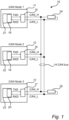
- FIG. 1 illustrates three CAN nodes 11, 12, 13 being connected to a linear passive CAN bus 14.
- a CAN bus is a multi-master serial communication bus which consist of two physical wires, CAN_H and CAN_L, being connected to a respective terminal of each CAN node. All CAN nodes (embodied in the form of e.g. ECUs) in a CAN network 10 are connected to these two wires.
- each CAN node 11, 12, 13 has a bus interface circuit; a CAN transceiver 15, 16, 17.
- Each transceiver comprises a transmitting part referred to as a bus driver and a receiving part referred to as a bus comparator (not shown).
- Each CAN node also has a CAN protocol controller 18, 19, 20 which handles protocol bit stream reception and transmission on data link layer according to ISO 11898-1.
- a microcontroller 21, 22, 23 is connected to the respective CAN protocol controller 18, 19, 20.
- the CAN protocol controllers may optionally be a part of the microcontrollers.
- the CAN protocol uses a serial bit stream with values o and 1, also known as dominant and recessive bits, which forms CAN data frames, CAN remote frames and other protocol symbols transmitted on the CAN bus 14.
- a CAN data frame is a "container" in which signals can be transported between two or more CAN nodes. The signals represent useful information shared between CAN nodes, e.g. vehicle speed, brake request, door lock request or similar.
- ISO-11898-1 define several CAN data frame formats, e.g. Classical Base Frame Format (CBFF), Classical Extended Frame Format (CEFF), Flexible Data-rate (FD) Base Frame Format (FBFF) and FD Extended Frame Format (FEFF).
- CBFF Classical Base Frame Format
- CEFF Classical Extended Frame Format
- FD Flexible Data-rate
- FBFF Flexible Data-rate
- FEFF FD Extended Frame Format
- All CAN nodes 11, 12, 13 are capable of transmitting frames to each other.
- the CAN protocol controller 18, 19, 20 is handling the reception and transmission of CAN frames.
- the transmitted bit values 0 and 1 from the CAN protocol controller are converted in the CAN transceiver 15, 16, 17 in each CAN node into two analog voltage levels on the CAN bus 14, which is referred to as recessive and dominant state.
- the recessive state is caused by recessive data (bits having value 1) being sent over the bus, while the dominant state is caused by dominant data (bits having value 0) being sent over the bus.
- These states relate to two voltage ranges on the CAN bus 14. For reception it is the reverse; the CAN transceiver 15, 16, 17 converts the two voltage levels on the CAN bus 14 into suitable levels to the CAN protocol controller 18, 19, 20.
- All CAN nodes have a wired-AND connection on CAN_H and CAN_L bus wires; all CAN nodes are directly connected to each other by connecting all the CAN_H wires, and all the CAN_L wires, respectively.
- Each CAN node 11, 12, 13 can drive the CAN bus 14 into a series of recessive/dominant states, enabling a multi-master communication network according to ISO 11898-1.
- the CAN protocol data link layer defines how this multi-master sharing of the network is performed, according to a carrier sense multiple access (CSMA) operation.
- CSMA carrier sense multiple access
- All data transmitted by the CAN nodes 11, 12, 13 are shared on the CAN bus 14 so all the CAN nodes receive the same stream of bits. If at least one CAN node transmit a dominant bit (logic 0), the CAN bus for all CAN nodes is dominant (logic 0), otherwise the CAN bus is recessive (logic 1).
- any CAN node can overwrite a recessive state (1) to become a dominant state (0); this is only allowed in certain restricted situations and is not done regularly for just any CAN frame.
- a CAN node cannot overwrite a dominant state (0) to become recessive (1). This is how CAN is designed and should operate.
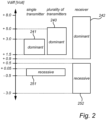
- Figure 2 illustrates stipulated voltage ranges on the CAN bus for recessive and dominant data transferred over the bus, according to standard ISO 11898-2.
- V diff expected CAN bus differential voltage
- the transmitter allowed voltage is in relatively narrow intervals (i.e. intervals 241 and 251) while the receiver must accept wider intervals (i.e. intervals 242 and 252) as recessive and dominant state respectively.
- the voltage V diff in dominant state must be between + 1.5 V and + 3.0 V on the transmitting CAN node output at normal bus resistance of 50 ⁇ to 65 ⁇ .
- the actual dominant data voltage falls anywhere within this voltage range but is more or less fixed, with slight variation over temperature and loading from bus termination components and impedance of the CAN cables.
- the V diff voltage can be above +3.0V, as illustrated with range 240. This will be described in more detail in the hereinbelow.
- the V diff dominant voltage may vary from ECU to ECU within the range + 1.5 V - +3.0V.
- the variation is due to several reasons like transceiver hardware production tolerances, different transceiver brand designs, temperature, ageing and so on. These many reasons are partly why the allowed range from + 1.5 V to +3.0V exists, to give a robust and tolerant system even with large differences in voltage levels on the same CAN network.
- V diff is in the range from + 1.5 V to +3.0V; +0.05 to -0.5V for a recessive transmit and +0.5V to -3.0V for a recessive receive.
- V diff is in the range from + 1.5 V to +3.0V; +0.05 to -0.5V for a recessive transmit and +0.5V to -3.0V for a recessive receive.
- receiver voltages between 0.5V and 0.9V it is undefined the resulting state but normally there is a recessive-to-dominant and dominant-to-recessive state transition with hysteresis implemented.
- an attacker device when attempting to manipulate a CAN frame, an attacker device will modify bits of a CAN frame transmitted by a vehicle ECU. Any bits of a frame is modified in any direction, from recessive (1) to dominant (0), or from dominant (0) to recessive (1) as needed in order to modify a signal value on the CAN bus 14, e.g. to change a door lock signal from LOCK to UNLOCK.
- Figures 3-7 show examples of possible attempts to manipulate data sent over the CAN bus 14.
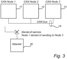
- FIG 3 shows a so-called denial-of-service (DOS) attack where an attacker device 30 having access to the CAN bus 14 hinders the first CAN node 11 to send data to second CAN node 12 or third CAN node 13, or to have the data sent by the first CAN node 11 become invalid.
- DOS denial-of-service
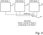
- Figure 4 shows a spoofing attack by the second CAN node 12 pretending to be the first CAN node 1 upon sending data to the third CAN node 13.
- an attacker device could be a device already included in the CAN network (being configured with malicious hardware or software) and not necessarily an external attacker device forcefully connecting to the bus.
- Figure 5 shows a spoofing attack by an external attacker device 30 pretending to be the first CAN node 11 upon sending data to the third CAN node 13.
- Figure 6 shows a tampering attack by attacker device 30 modifying data sent from the first CAN node 11 to the third CAN node 13.
- an attacker device could be a device already included in the CAN network and not necessarily an external attacker device forcefully connecting to the bus.
- FIG. 7 shows a so-called replay attack where an attacker device 30 having access to the CAN bus 14 in a first step (top view) records a normal data transmission from the first CAN node 11 to the third CAN node 13. Thereafter in a second step (bottom view), the attacker device 30 replays the recorded data transmission to the third CAN node 13 pretending to be the first CAN node 11
- manipulating a CAN network may be envisaged.
- "manipulation”, “modification” and “tampering” will alternatingly be used to illustrate a scenario where an attacker modifies bits of one or more CAN data frames, or creates new CAN data frames, to cause one or more CAN nodes to behave in a particular way or cause the CAN nodes to perform some particular action.
- CAN devices such as diagnostic on-board diagnostics (OBD)-II-dongles, devices for automated generation of driving logbooks, driving style monitoring devices provided by car insurance companies are attached temporarily or permanently to a vehicle CAN bus may be modified for malicious purposes.
- OBD diagnostic on-board diagnostics
- the normal CAN transceiver cannot itself determine whether or not tampering occurs.
- the CAN transceiver will accept both normal and manipulated frames as long as the differential bus voltage V diff comply with voltage ranges 242 and 252 of Figure 2 regardless of how these voltages are accomplished.
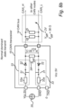
- Figures 8a and 8b show a schematic view of the transmitter part - i.e. the bus driver - of each CAN transceiver 15, 16, 17 acting as an interface of each CAN node 11, 12, 13 to the CAN bus 14.
- each termination resistance is 120 ⁇ , to match the typical CAN bus cable or transmission line impedance of 120 ⁇ .
- the following descriptions are based on a configuration of two 120 ⁇ termination resistors 24, 25, a single 60 ⁇ resistor, or any other form of bus resistance of 60 ⁇ accomplished by termination/transceiver components.
- the invention is not limited to these resistor/impedance values but may be used with any resistance/bus impedance.
- the resistance of bus biasing resistors 34 are disregarded in the following as they thus have insignificant influence on bus resistance and bus impedance.
- the characteristic differential resistance and impedance of the CAN bus 14 is about 60 ⁇ in normal recessive state during an idle bus state and during transmission of recessive data to the CAN bus 14.
- FET field-effect transistor
- CAN transceiver 15 transmitting dominant state on the CAN bus 14.
- a commonly used supply voltage Vcc for normal CAN transceivers used in motor vehicles is +5.0V.
- a typical V diff dominant drive capability when one CAN node transmit dominant data into a 60 ⁇ bus resistance is +2.0V (although the full + 1.5 V to +3.0V range is allowed and also used in motor vehicles).
- the CAN bus impedance and CAN transceiver impedance can be calculated.
- the CAN transceiver 15 and CAN bus termination resistors 24, 25 form a voltage divider, dividing the CAN transceiver Vcc supply voltage down to a lower voltage V diff on the CAN bus 14.
- the internal resistance of the CAN transceiver 15 is about 90 ⁇ since there is a total voltage drop of 3.0V over the transceiver and a current of 0.033A flows through the transceiver.
- Vcc voltage supply 35 is around 0 ⁇ and since it is connected in series with each transceiver drive stage 33, 0 ⁇ is added to transceiver internal resistance 90 ⁇ for a total internal resistance and impedance of 90 ⁇ of power supply and transceiver.
- the bus driver switches 31, diodes 32, and internal resistance 33a in Figure 8b is a simplified schematic of the internal components of a bus driver. They form two identical bus driver stages 33.
- the transceiver internal resistance and resulting CAN bus impedance will be different but still significantly lower than 60 ⁇ in recessive state.
- CAN nodes can start frame transmission at the same time.
- SOF Start-Of-Frame
- the ISO-11898-2 specification allows a bus voltage V diff that exceed the normal range of + 1.5 V to +3.0V, i.e. range 241 in Figure 2 .
- a bus voltage of up to +5.0V is allowed, i.e. range 240 in Figure 2 . This applies at a bus resistance of 70 ⁇ .
- Typical implementations of CAN bus transceivers used in motor vehicles use two drive stages 33 where the resulting dominant bus voltage is strongly dependent on the bus load.
- a higher load lower resistance value of termination resistors
- a lower load higher resistance value of termination resistors, or driving only a part of the current into the termination resistors as is the case during simultaneous SOF and dominant bits of arbitration field, ACK bit
- ACK bit lower resistance value of termination resistors
- a bus voltage below +5.0V can be expected, such as for instance a bus voltage of +4.6V.
- a bus impedance near 4.8 ⁇ is expected also during ACK bit (always dominant) in ACK field where all but one receiver (31 in a network with 32 CAN nodes) simultaneously transmit ACK.
- ACK bit always dominant
- a corresponding lower number of CAN nodes transmit ACK and hence resulting bus impedance may be higher than 4.8 ⁇ .
- Figure 8b shows a single CAN transceiver 15 with a single power supply 35.
- the resulting CAN transceiver internal resistance applies here as well, and becomes coupled in parallel with CAN bus 14, and bus impedance is calculated in the same way.
- the attacker device 30 is equipped with a special-purpose CAN transceiver/bus driver that switch a dominant voltage and has low internal resistance and impedance of 4 ⁇ to force a dominant bus state onto the CAN bus 14.
- the characteristic impedance of the CAN bus 14 will fall far below 36 ⁇ .
- the attacker device 30 thus needs to be equipped with a special-purpose CAN transceiver/bus driver that switch a low impedance load in the order of only a few ohms on the CAN bus 14 to load the CAN transceiver 15 of the CAN node. While providing a dominant bus voltage, this bus load is significantly heavier than what a normal CAN transceiver 15 is designed for and will reduce the differential voltage V diff (from being dominant in the range 242 of Figure 2 ) so much that the voltage on the CAN bus 14 will be below 0.5V or even negative and thus recessive (i.e. in the voltage range 252 of Figure 2 ).
- the special-purpose CAN transceiver of the attacker device 30 may in another example switch a voltage supply with a voltage (not shown) below or under +0.5V or even negative and cause the voltage on CAN bus to be in the recessive range of 252 in Figure 2 .
- the attacker may in other examples switch a ground potential 0V and a vehicle power supply voltage +12V and cause the voltage on CAN bus to be in the recessive range.
- a normal CAN transceiver 15 in a CAN node 11 cannot supply enough current (maximum supply current I CAN_H , I CAN _ L amounts to 115mA as specified in ISO-11898-2:2017) to the CAN bus 14 in order to maintain a dominant voltage and win over the attacker device 30 special-purpose CAN transceiver/bus driver low impedance load or low voltage source forcing recessive voltage.
- this constraint on a CAN node may be successfully exploited by the attacker device 30, which can be designed to supply significantly larger currents than 115mA.
- the attacker device may intentionally overload the normal CAN transceiver 15 knowing it is guaranteed to provide maximum 115mA.
- the attacker device 30 have few physical layer constraints other than that it needs to accomplish the CAN bus voltages of ranges 242/252 of Figure 2 , not necessarily the voltages 241/251.
- the maximum usable internal resistance 38 of an attacker device 30 connected in parallel with a bus resistance (represented by 24, 25) driven to dominant state by CAN transceiver 15 is determined by the upper threshold of the recessive bus voltage +0.5V of transceiver 15, i.e. range 252 in Figure 2 .
- the maximum bus currents provided at dominant is far below 115mA. In such case the maximum attacker resistance capable of forcing recessive voltage is therefore higher than 4.6 ⁇ . In some implementations of CAN transceivers used in motor vehicles, an attacker resistance of 5 to 10 ⁇ can force the bus voltage to be recessive.
- An attacker may not know beforehand what data, recessive or dominant, a transmitting CAN node 15 is about to transmit in e.g. bits of a data field.
- the attacker may try to force recessive or dominant state on a CAN bus 14 without beforehand considering what CAN node 15 transmits, and some bits may be the same data as transmitted by CAN node 15.
- the bus state, recessive or dominant does not actually change but remains the same.
- the bus impedance will be manipulated.
- the bus resistance and impedance is 60 ⁇ and the attacker attempts to force recessive state as well, and switch a resistive load of 4 ⁇ which becomes coupled in parallel with the bus.
- the characteristic impedance of the CAN bus 14 in recessive state is manipulated and will fall far below 60 ⁇ .
- the characteristic impedance of the CAN bus 14 in dominant state is manipulated and will fall far below 36 ⁇ .
- the resulting bus voltage, bus current, transceiver currents, transceiver internal impedances, resulting bus impedances, will be different.
- the voltages or resistance of an attacker device required for bus manipulation may be different but will follow the principles described in before.
- a device is arranged such that it may detect a change in CAN bus impedance (by measuring an appropriate electrical property of the CAN bus 14 such as actual impedance or indirectly by measuring bus voltage and/or current) from a first expected impedance to a second lower impedance.
- Other electrical properties include for instance bus common mode voltage, single ended bus voltage, single ended bus impedance of either CAN_L or CAN_H wires, etc.
- the CAN bus state is determined to be recessive (i.e. at a voltage within range 242 of Figure 2 ) or dominant (i.e. at a voltage within range 252 of Figure 2 ) based on the actual bus voltage determined by a CAN receiver (bus comparator).
- the actual bus voltage may or may not be the result of a manipulated bus state by means manipulation of bus resistance or impedance.
- the determined bus state (recessive or dominant) control an impedance threshold used for determining bus impedance to be normal or a result of manipulation.
- the device will detect whether the CAN bus impedance is below a predetermined threshold value. If so, the device is given an indication that data on the CAN bus 14 may be manipulated.
- such a device 100 could be embodied as a "sniffer" easily connectable to the CAN bus 14 for detecting the above-discussed change in CAN bus impedance with an impedance detection component 101.
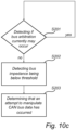
- Figure 10b showing a flowchart illustrating a method of detecting manipulation of data on the CAN bus 14 according to an embodiment.
- the sniffer device 100 could thus, upon detecting the steep change in CAN bus impedance in step S101 utilizing the impedance detection component 101, say from a first value of 36 ⁇ down to a second value of about 3-4 ⁇ (as discussed with reference to Figure 9b ), alert each CAN node 11, 12, 13, or some central controller (not shown), whereupon the CAN nodes 11, 12, 13 may conclude that a CAN frame currently being transported over the CAN bus 14 should be discarded. It may for security reasons be decided that a plurality of CAN frames are to be discarded when this decrease in bus impedance is detected. It is noted that the sniffer device 100 does not need to determine that there is a decrease in impedance between two values, but simply needs to conclude that a bus impedance value is below a predetermined threshold value such as e.g. 5 ⁇ or 10 ⁇
- the bus impedance may decrease significantly from 36 ⁇ to 3-4 ⁇ also during normal dominant state data transmission. Such a situation may occur during transmission of a SOF bit to signal start of a CAN frame transmitted over the CAN bus and the following bus arbitration, since when several CAN nodes simultaneously transmit dominant, their bus drivers are operating in parallel and are therefore reducing the total bus impedance.
- the sniffer device 100 will further be equipped with a CAN frame decoder 102.
- the SOF bit is detected by a CAN node, which indicates the start of the CAN data frame.
- the arbitration field is comprised of an 11-bit IDENTIFIER field and a following remote transmission request (RTR) bit.
- the IDENTIFIER field will identify which CAN node is the transmitter of the CAN frame. In other words, the arbitration occurs during transmission of the IDENTIFIER field and RTR bit (i.e. 12 bits) in order to determine/identify which one out of a plurality of CAN nodes will gain access to the bus for CAN frame transmission.
- a CAN data frame according to the CBFF format further comprises an identifier extension (IDE) bit, a flexible data-rate frame (FDF) bit, a 4-bit data length code (DLC) field, up to 64 data bits (in case of a data frame), 15-bit cyclic redundancy checksum (CRC) field, a CRC delimiter bit, an acknowledge (ACK) bit, an ACK delimiter bit, and a 7-bit end-of-frame (EOF) field.
- IDE identifier extension
- FDF flexible data-rate frame
- DLC data length code
- CRC cyclic redundancy checksum
- ACK acknowledge
- EEF end-of-frame
- the arbitration field is comprised of an 11-bit IDENTIFIER field, a substitute remote request (SRR) bit, an IDE bit, an 18-bit IDENTIFIER extension field and an RTR bit (i.e. 32 bits).
- the arbitration field is comprised of an 11-bit IDENTIFIER field and an RTR bit (i.e. 12 bits).
- the arbitration field is comprised of an 11-bit IDENTIFIER field, an SRR bit, an IDE bit, an 18-bit IDENTIFIER extension field and a remote request substitution (RRS) bit (i.e. 32 bits).
- RTS remote request substitution
- the CAN frame decoder 102 will enable the sniffer device 100 to detect in step S102 the SOF bit and the IDENTIFIER bit field in order to determine if the detection that the bus impedance steeply decreases from 36 ⁇ down to around 3-4 ⁇ occurs during possible CAN bus arbitration. If so, the decrease in impedance will not be considered to be the result of a malicious bus manipulation attempt, but a consequence of normal ongoing arbitration on the CAN bus 14 (and continuing impedance measurements would typically be performed). It is noted that the CAN frame decoder 102 of the sniffer device 100 detects the IDENTIFIER field during which arbitration may occur but will not detect the actual arbitration occurring on the CAN bus 14.
- step S103 advantageously determine that the steep increase in bus impedance is a result of a manipulation attempt.
- the sniffer device 100 in this embodiment not must be equipped with a CAN transmitter.
- the sniffer device 100 would only have to be equipped with the CAN bus comparator (i.e. CAN receiver), but not with the CAN bus driver (i.e. CAN transmitter), since the sniffer device 100 only receives data from the CAN bus 14 but does not transmit any data to the CAN bus 14.
- the CAN frame decoder 102 could comprise a CAN protocol controller 18, 19, 20 of the type included in the CAN nodes 11, 12, 13 t decode the received CAN data frames even though the CAN frame decoder 102 used in the sniffer device 100 strictly must not be equipped with any capability for encoding data into CAN frames to be transmitted over the CAN bus 14.
- the sniffer device 100 first detects in step S201 whether or not arbitration may currently occur, and if so, refrain from detecting any change in bus impedance during the potential arbitration procedure currently occurring on the CAN bus 14.
- detection of bus impedance in step S202 will only be performed as long as no arbitration may be currently ongoing.
- the sniffer device 100 detects that the bus impedance steeply decreases from 36 ⁇ down to around 3-4 ⁇ in step S202 and no arbitration field is currently encountered (as determined in previous step S201) on the CAN bus - i.e. no IDENTIFIER data and RTR bit are transmitted - a malicious CAN bus manipulation attempt is considered to have been detected in step S203, and the CAN nodes 11, 12, 13, or a central unit, are alerted accordingly such that the attempt can be warded off.
- the CAN frame decoder 102 of the sniffer device 100 detects the SOF bit and thus knows that the following 11 bits belong to the IDENTIFIER field followed by a single RTR bit, the transmission of which signals indicates a potential arbitration occurring. Thus, any dominant data transmitted in the arbitration field potentially indicates an arbitration occurring.
- a CAN frame decoder is aware of the configuration of the current field of a CAN data frame (or CAN remote frame) being encountered on the CAN bus (arbitration field, control field, data field, etc.). After these 13 bits have passed (i.e.
- the impedance detection component 101 of the sniffer device 100 will perform the detection of a decrease in CAN bus impedance.
- any detection of a decrease in CAN bus impedance at dominant state occurring during these 13 bits being transferred on the bus is disregarded.
- Other frame formats may be used and may include a different length of the arbitration field and identifier field, e.g. CEFF, FEFF, FBFF, as previously described.
- this decrease in CAN bus impedance occurs (as indicated by the bus impedance being below a predetermined threshold value) during the ACK bit sent simultaneously on the CAN bus 14 by a plurality of CAN nodes, the decrease is not considered to be a result of CAN bus manipulation as it could occur during normal operation.
- no impedance detection is performed during the ACK bit being transferred.
- An advantage of embodying the device as a sniffer device 100 easily connectable to the CAN bus 14 is that such a device could be added to an already available CAN network 10 without greater modifications.
- the device may be integrated with a CAN transceiver, thus creating an enhanced CAN transceiver capable of full-scale CAN data communication as well as bus impedance detection.
- the sniffer device 100 of Figure 10a has the advantage that it is relatively non-complex in terms of functionality and is not required to be equipped with all the components of a far more complex CAN transceiver.
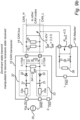
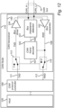
- Figure 12 illustrates a further embodiment previously referred to as an enhanced CAN transceiver 150 to be integrated with a CAN node 110, for instance an ECU.
- the CAN node 110 comprises a CAN protocol controller 180 (cf. CAN protocol controllers 18, 19, 20 of Figure 1 ) configured to transport data to/from host 130, being for instance a door lock module or similar.
- the enhanced CAN transceiver 150 comprises a bus comparator 103 and a bus driver 104 complying with the voltage levels previously described with reference to Figure 2 .
- the enhanced CAN transceiver 150 further comprises an impedance detection component 101 similar to the sniffer device 100 according to the embodiment described with reference to Figures 10a-c configured to detect if the CAN bus impedance is around 3-4 ⁇ (or at least under 10 ⁇ ).
- the enhanced CAN bus transceiver 150 comprises a CAN frame decoder 102 configured to decode CAN data frames and CAN remote frames transmitted over the CAN bus 14 (and received via line 108) in order to detect a SOF bit and a following IDENTIFIER data field indicating that arbitration may occur.
- the CAN frame decoder 102 may control the impedance detection component 101 (via line 106) to measure the CAN bus impedance only if the CAN receiver 102 detects that no potential arbitration occurs (i.e. no SOF bit + IDENTIFIER data field and RTR bit are detected on the bus 14), since a steep decrease in bus impedance may occur during normal operation with a SOF bit or IDENTIFIER data field being encountered on the CAN bus 14.
- the CAN frame decoder 102 may be implemented using a full CAN protocol controller, even though the CAN frame decoder 102 is not used for encoding data into CAN frames to be transmitted over the CAN bus 14 but for decoding CAN data frames received over the CAN bus 14.
- CAN frame decoder 102 in cooperation with the impedance detection component 101 detects that bus impedance is below a threshold value when no arbitration can occur (cf. steps S101 and S102 of Figure 10b or steps S202 and S201 of Figure 10c ), i.e. outside of the SOF bit and the IDENTIFIER data field and RTR bit being encountered, a malicious CAN bus manipulation attempt is considered to have been detected (cf. step S103 of Figure 10b or step S203 of Figure 10c ).
- CAN controller 180 For a normal, untampered CAN bus there is a need for non-interference with the transmission and reception of normal CAN data frames from the CAN controller 180 to and from the CAN bus 14. This concerns e.g. the timing properties of frames and data content of frames.
- Received CAN data frames will thus pass via the bus comparator 103 to the CAN protocol controller 180 via RXD line 112.
- the CAN protocol controller 180 will then pass payload data of the CAN data frame (i.e. the DATA field of the frame illustrated in Figure 11 ) to the host 130.
- Transmitted CAN frames will pass from CAN controller 180 via TXD line 111 to the bus driver 104 and to the CAN bus 14.
- a first switch 114 is introduced which can be controlled by the CAN frame decoder 102 in case any manipulation attempt is detected as previously described.
- the CAN frame decoder 102 may discard the potentially manipulated CAN frame by controlling the first switch 114 via line 107 such that the CAN protocol controller 180 receives dominant data e.g. an error flag (EF) comprised of at least six consecutive bits (represented by "o") instead of the potentially manipulated CAN data frame(s).
- EF error flag
- a second switch is 113 introduced to avoid any erroneous response from the CAN protocol controller 180 transmitted via TXD line 111.
- the CAN frame decoder 102 may discard a response signal from the CAN protocol controller 180 by controlling the second switch 113 via line 107 to output recessive data (represented by "1") to the CAN bus 14 via the bus driver 104.
- a received frame Since a received frame is to be approved or disapproved based on the bus electrical properties, and the enhanced CAN transceiver 150 must preserve the timing and content of untampered frames, it must initially allow reception of the beginning of a received frame until the frame is later possibly detected as tampered; that can only be determined after the part of the CAN frame constituting the SOF bit and the IDENTIFIER data field + the RTR bit have been decoded by the CAN frame decoder 102 and the same part already has been passed on to the CAN protocol controller 180. If the CAN frame is not detected to be manipulated, the complete CAN frame must be passed transparently until its end. Therefore, there is a need for determining the start of a new received frame, which a CAN frame decoder 102 (possibly implemented using a full CAN protocol controller) indeed is capable of doing.
- the CAN data link protocol defined in ISO-11898-1 define an approach of signalling errors (invalidating received frames) when errors are detected (e.g. CRC error, stuff error, format error) on the data link layer. If a received CAN data frame is detected to have been tampered with, this decision is made during the tampered bit or a bit following closely after the bit having been tampered with. Such decision must always be made before the CAN frame has ended in order to prevent the CAN frame from being considered valid and received by CAN controller 180.
- CRC error CRC error
- stuff error format error
- the ISO-11898-1 approach of invalidating a received frame is in an embodiment used also by the enhanced CAN transceiver 150 to discard a possibly manipulated received CAN frame.
- This invalidation is internal in the CAN transceiver 150 and CAN node 110 and is not transmitted on the CAN bus 14.
- the CAN frame decoder 102 controls the first switch 114 to discard the received CAN frame by effectively destroying the CAN frame passed via RXD line 112 by overwriting the CAN frame with an error flag (EF) that present a logic 0 for a duration of at least six consecutive bits duration.
- EF error flag
- the error flag is extended beyond six bits or until the end of CAN data frame has been encountered on the bus 14, as determined by the CAN frame decoder 102.
- Overwriting the remainder of the CAN frame in this way will a) prevent the CAN protocol controller 180 from receiving the frame as a valid frame and will thus prevent the frame content to be passed from the CAN protocol controller 180 and onto the host 130, and b) have the CAN protocol controller 180 not detect bus idle before the end of frame has been encountered and thereby wait with any pending frame transmission until the CAN bus 14 is idle.
- the host 130 will be unaware of any tampered CAN frame.
- the CAN frame decoder 102 may in an optional embodiment, while invalidating the received CAN frame on RXD signal 112, acknowledge the tampered CAN frame on the CAN bus 14 by transmitting a dominant bit on the TXD signal 111 during ACK bit in ACK field. This will hide the detection of a tampered CAN frame by CAN transceiver 150 to an attacker or any other CAN node on the CAN bus 14. Thus, CAN node 110 will appear to accept the tampered frame while internally actually discarding it.
- the impedance detection component 101 may sense the CAN bus impedance during bit reception of a CAN frame which coincide with one or more bit time segments defined by ISO-11898-1; Sync_Seg, Prop_Seg, Phase_Seg 1, Phase_Seg 2 or around the sampling point. Impedance sensing may also be continuous.
- CAN bus impedance detection may be performed such that it does not timewise coincide with transitions of the bus state from dominant-to-recessive or recessive-to-dominant, or it is not performed at a predetermined time thereafter.
- normal untampered CAN data frames may transparently be passed to and from a host 130 and a CAN bus 14, while any CAN data frame(s) detected to potentially be manipulated is blocked from reaching the host 130 (and/or the CAN bus 14), thereby preventing tampering and any following vehicle malfunction.
- an alternative usage is envisaged.
- a vehicle system designer or original equipment manufacturer (OEM) may want to allow activation of certain function or vehicle mode via CAN bus communication and only when having physical access to the vehicle for security or safety reasons, e.g. in a workshop or during R&D development.
- Other reasons may be to unlock, disable or enable certain vehicle functionality only under strictly controlled situation, and that may be subject to commercial or data integrity reasons for the OEM, e.g. increasing propulsion system performance (torque, horsepower) or reading sensitive vehicle data.
- propulsion system performance torque, horsepower
- reading sensitive vehicle data it may be possible to in fact want to test robustness of the CAN network or how the CAN network reacts to malicious attacks.
- the CAN receiver 102 instead of discarding any detected manipulated CAN data frames (provoked by the vehicle system designer or the OEM), the CAN receiver 102 detects the manipulated CAN data frames and controls the first switch 114 to forward the manipulated CAN data frames instead of discarding the frames. It could even be envisaged that manipulated CAN frames are forwarded to the CAN protocol controller 180 and further on to the host 130 while the normal, non-manipulated CAN data frames are discarded.
- the sniffer device 100 and the enhanced CAN transceiver 150, respectively, comprises functionality such as impedances detection 101 and CAN frame decoding 102, which may be implemented using an appropriate component(s).
- the devices according to embodiments - represented here by the enhanced CAN transceiver 150 - comprise one or more processing units 200 in which parts or all of the functionality described hereinabove of may be implemented.
- processing unit(s) 200 such as that of the CAN frame decoder 102, the bus impedance detector 101, switches 113, 114, etc.
- the steps of the method of the CAN transceiver 150 (or sniffer device 100) of detecting manipulation of data on a CAN bus to which the device is connected may thus in practice be performed by the processing unit 200 embodied in the form of one or more microprocessors arranged to execute a computer program 220 downloaded to a suitable storage medium 210 associated with the microprocessor, such as a Random Access Memory (RAM), a Flash memory or a hard disk drive.
- RAM Random Access Memory
- Flash memory or a hard disk drive.
- the processing unit 200 is arranged to cause the device 150 to carry out the method according to embodiments when the appropriate computer program 220 comprising computer-executable instructions is downloaded to the storage medium 210, being e.g. a non-transitory storage medium, and executed by the processing unit 200.
- the storage medium 210 may also be a computer program product comprising the computer program 220.
- the computer program 220 may be transferred to the storage medium 210 by means of a suitable computer program product, such as a Digital Versatile Disc (DVD) or a memory stick.
- DVD Digital Versatile Disc
- the computer program 220 may be downloaded to the storage medium 210 over a network.
- the processing unit 200 may alternatively be embodied in the form of a digital signal processor (DSP), an application specific integrated circuit (ASIC), a field-programmable gate array (FPGA), a complex programmable logic device (CPLD), a system basis chip (SBC), etc.
- DSP digital signal processor
- ASIC application specific integrated circuit
- FPGA field-programmable gate array
- CPLD complex programmable logic device
- SBC system basis chip
- the CAN transceiver 150 may be an Integrated Circuit (IC) packaged device with a bus driver and a bus comparator in the same IC package.
- the transceiver 150 may be constructed by a plurality of passive components and by linear or digital semiconductor components.
- the bus driver 104 and bus comparator 103 may be embodied by an Integrated Circuit (IC) in the same IC package, for instance a prior art CAN transceiver, and bus characteristics sensor 101, CAN frame decoder, 102, switches 113, 114 may be separate the from the transceiver IC package.
- IC Integrated Circuit
Description
- The present disclosure relates to a method of detecting manipulation of data on a Controller Area Network (CAN) bus, and a device performing the method.
- The automotive industry have for many years been using message-based communication protocols between electronic control units (ECUs) embedded in motor vehicles and crafts such as cars, boats, trucks, etc. An example of such a protocol is Controller Area Network (CAN). This protocol is standardized by International Standards Organization (ISO). For instance, the CAN protocol used in automotive is defined by ISO standard ISO 11898, consisting of several sub-specifications addressing different parts; for example the CAN datalink layer is defined by ISO 11898-1:2016 and CAN high speed physical layer is defined by ISO 11898-2:2017. ISO define other CAN protocols as well, which are also used in motor vehicles.
- An aspect that has become increasingly relevant in recent years is in-vehicle-network (IVN) security and vehicle data integrity. There are several attack methods like spoofing, tampering, denial-of-service (DOS) that are relevant threats. Some threats are coming from inside vehicle itself in the form of malicious software downloaded to the vehicle, and some threats are coming from external attacker with physical access to the vehicle and its internal communication networks.
- As an example, a door lock module could be tampered with by a malicious party with the intent to unlock a vehicle which the malicious party is not authorized to unlock. Any such attacks should be detected and prevented.
- Several methods are known for mitigation or prevention of various attacks on the data link layer of CAN bus systems. However, in some examples these methods can be successfully circumvented by performing combined attacks on data link layer and physical layer, when having physical access to a CAN bus.
-
US 2018/0069874 discloses an attack detection apparatus that detects an attack against a communication network between devices, and improves information security of the communication network. The attack detection apparatus has a CAN that transfers a signal to a plurality of nodes by a differential voltage between two signal lines, and a short circuit detector that monitors the signal transferred by the two signal lines of the CAN, and detects a short circuit between the two signal lines on the basis of a change in the signal indicating a characteristic of a short circuit attack by an unauthorized node. -
WO 2019/035112 discloses a computer implemented method of disabling a malicious ECU of a plurality of ECUs in communication with a CAN bus network, the method executed by a computing device in communication with the plurality of ECUs and the CAN bus network. The method comprises detecting a malicious message transmitted by the malicious ECU over the CAN bus network, and injecting a plurality of bits over the CAN bus network to trigger a predefined plurality of errors for disabling the malicious ECU before the malicious ECU makes an additional attempt to retransmit an additional instance of the malicious message. - One objective is to solve, or at least mitigate, this problem in the art and thus to provide a method of detecting, and possibly preventing, manipulation of data on a CAN bus.
- This is performed by a method of a device of detecting manipulation of data on a CAN bus to which the device is connected. The method comprises detecting that bus impedance is below a threshold bus impedance value, detecting whether or not CAN node arbitration currently may occur on the CAN bus upon detecting that the bus impedance is below the threshold bus impedance value, and if not determining that an attempt to manipulate data on the CAN bus has occurred.
- Generally, all terms used in the claims are to be interpreted according to their ordinary meaning in the technical field, unless explicitly defined otherwise herein. All references to "a/an/the element, apparatus, component, means, step, etc." are to be interpreted openly as referring to at least one instance of the element, apparatus, component, means, step, etc., unless explicitly stated otherwise. The steps of any method disclosed herein do not have to be performed in the exact order disclosed, unless explicitly stated.
- Aspects and embodiments are now described, by way of example, with reference to the accompanying drawings, in which:
-
Figure 1 shows three CAN nodes forming a CAN network in which embodiments may be implemented; -
Figure 2 illustrates stipulated voltage ranges on the CAN bus for recessive and dominant data transferred over the bus, according to standard ISO 11898-2; -
Figure 3 shows a denial-of-service attack; -
Figure 4 shows a spoofing attack; -
Figure 5 shows an alternative spoofing attack; -
Figure 6 shows a tampering attack; -
Figure 7 shows a replay attack; -
Figures 8a and8b show a schematic view of a transmitter part of a CAN transceiver acting as an interface to a CAN bus; -
Figure 9a and9b shows an attacker device and a CAN transceiver being connected to a CAN bus; -
Figure 10a illustrates a device according to an embodiment configured to detect manipulation of data on a CAN bus to which the device is connected; -
Figure 10b shows a flowchart of a method of detecting manipulation of data on a CAN bus according to an embodiment; -
Figure 10c shows a flowchart of a method of detecting manipulation of data on a CAN bus according to another embodiment; -
Figure 11 shows a prior art CAN data frame in a Classical Base Frame Format (CBFF); and -
Figure 12 illustrates a device according to another embodiment configured to detect manipulation of data on a CAN bus to which the device is connected; and -
Figure 13 illustrating a device according to an embodiment. - The present invention is defined in the appended independent claims to which reference should be made. Advantageous features are set out in the appended dependent claims.
- The aspects of the present disclosure will now be described more fully hereinafter with reference to the accompanying drawings, in which certain embodiments of the invention are shown.
-
Figure 1 illustrates threeCAN nodes passive CAN bus 14. A CAN bus is a multi-master serial communication bus which consist of two physical wires, CAN_H and CAN_L, being connected to a respective terminal of each CAN node. All CAN nodes (embodied in the form of e.g. ECUs) in aCAN network 10 are connected to these two wires. - Internally, each
CAN node CAN transceiver - Each CAN node also has a
CAN protocol controller microcontroller CAN protocol controller passive CAN bus 14, there are normally twotermination resistors - The CAN protocol uses a serial bit stream with values o and 1, also known as dominant and recessive bits, which forms CAN data frames, CAN remote frames and other protocol symbols transmitted on the
CAN bus 14. A CAN data frame is a "container" in which signals can be transported between two or more CAN nodes. The signals represent useful information shared between CAN nodes, e.g. vehicle speed, brake request, door lock request or similar. ISO-11898-1 define several CAN data frame formats, e.g. Classical Base Frame Format (CBFF), Classical Extended Frame Format (CEFF), Flexible Data-rate (FD) Base Frame Format (FBFF) and FD Extended Frame Format (FEFF). - All
CAN nodes protocol controller bit values CAN transceiver CAN bus 14, which is referred to as recessive and dominant state. - That is, the recessive state is caused by recessive data (bits having value 1) being sent over the bus, while the dominant state is caused by dominant data (bits having value 0) being sent over the bus. These states relate to two voltage ranges on the
CAN bus 14. For reception it is the reverse; theCAN transceiver CAN bus 14 into suitable levels to theCAN protocol controller - All CAN nodes have a wired-AND connection on CAN_H and CAN_L bus wires; all CAN nodes are directly connected to each other by connecting all the CAN_H wires, and all the CAN_L wires, respectively. Each
CAN node CAN bus 14 into a series of recessive/dominant states, enabling a multi-master communication network according to ISO 11898-1. The CAN protocol data link layer defines how this multi-master sharing of the network is performed, according to a carrier sense multiple access (CSMA) operation. - All data transmitted by the
CAN nodes CAN bus 14 so all the CAN nodes receive the same stream of bits. If at least one CAN node transmit a dominant bit (logic 0), the CAN bus for all CAN nodes is dominant (logic 0), otherwise the CAN bus is recessive (logic 1). - This means that any CAN node can overwrite a recessive state (1) to become a dominant state (0); this is only allowed in certain restricted situations and is not done regularly for just any CAN frame. A CAN node cannot overwrite a dominant state (0) to become recessive (1). This is how CAN is designed and should operate.
-
Figure 2 illustrates stipulated voltage ranges on the CAN bus for recessive and dominant data transferred over the bus, according to standard ISO 11898-2. - In
Figure 2 details are shown for expected CAN bus differential voltage (referred to as Vdiff) values measured between CAN_H and CAN_L wires, for the transmitter part of a CAN transceiver (i.e. the bus driver) and the receiver part of a CAN transceiver (i.e. the bus comparator), where Vdiff is measured as the voltage VCAN_H from bus wire CAN_H to ground, subtracted by the voltage VCAN_L from bus wire CAN_L to ground. The transmitter allowed voltage is in relatively narrow intervals (i.e.intervals 241 and 251) while the receiver must accept wider intervals (i.e.intervals 242 and 252) as recessive and dominant state respectively. This results in receiver tolerance against differences among the Vdiff voltages of the CAN nodes. The voltage Vdiff in dominant state must be between +1.5V and +3.0V on the transmitting CAN node output at normal bus resistance of 50 Ω to 65 Ω. For a given CAN node, the actual dominant data voltage falls anywhere within this voltage range but is more or less fixed, with slight variation over temperature and loading from bus termination components and impedance of the CAN cables. In some situations, when more than one CAN node simultaneously transmit dominant (up to 32 CAN nodes may be connected to the bus), the Vdiff voltage can be above +3.0V, as illustrated withrange 240. This will be described in more detail in the hereinbelow. - For a population of ECUs (i.e. a CAN node) in a single vehicle or a fleet of vehicles, the Vdiff dominant voltage may vary from ECU to ECU within the range +1.5V - +3.0V. The variation is due to several reasons like transceiver hardware production tolerances, different transceiver brand designs, temperature, ageing and so on. These many reasons are partly why the allowed range from +1.5V to +3.0V exists, to give a robust and tolerant system even with large differences in voltage levels on the same CAN network.
- A receiving ECU being compliant with ISO 11898-2 must accept a voltage Vdiff between the two CAN terminals from +0.9V to +8.0V as dominant. For a dominant transmit, Vdiff is in the range from +1.5V to +3.0V; +0.05 to -0.5V for a recessive transmit and +0.5V to -3.0V for a recessive receive. For receiver voltages between 0.5V and 0.9V it is undefined the resulting state but normally there is a recessive-to-dominant and dominant-to-recessive state transition with hysteresis implemented.
- Now, when attempting to manipulate a CAN frame, an attacker device will modify bits of a CAN frame transmitted by a vehicle ECU. Any bits of a frame is modified in any direction, from recessive (1) to dominant (0), or from dominant (0) to recessive (1) as needed in order to modify a signal value on the
CAN bus 14, e.g. to change a door lock signal from LOCK to UNLOCK. -
Figures 3-7 show examples of possible attempts to manipulate data sent over theCAN bus 14. -
Figure 3 shows a so-called denial-of-service (DOS) attack where anattacker device 30 having access to theCAN bus 14 hinders thefirst CAN node 11 to send data tosecond CAN node 12 orthird CAN node 13, or to have the data sent by thefirst CAN node 11 become invalid. -
Figure 4 shows a spoofing attack by thesecond CAN node 12 pretending to be thefirst CAN node 1 upon sending data to thethird CAN node 13. Hence, an attacker device could be a device already included in the CAN network (being configured with malicious hardware or software) and not necessarily an external attacker device forcefully connecting to the bus. -
Figure 5 shows a spoofing attack by anexternal attacker device 30 pretending to be thefirst CAN node 11 upon sending data to thethird CAN node 13. A spoofed frame may include a manipulated ACK field with ACK bit = 0 already indicating acknowledge. -
Figure 6 shows a tampering attack byattacker device 30 modifying data sent from thefirst CAN node 11 to thethird CAN node 13. Hence, an attacker device could be a device already included in the CAN network and not necessarily an external attacker device forcefully connecting to the bus. -
Figure 7 shows a so-called replay attack where anattacker device 30 having access to theCAN bus 14 in a first step (top view) records a normal data transmission from thefirst CAN node 11 to thethird CAN node 13. Thereafter in a second step (bottom view), theattacker device 30 replays the recorded data transmission to thethird CAN node 13 pretending to be thefirst CAN node 11 - As can be concluded, numerous ways of manipulating a CAN network may be envisaged. In the following, "manipulation", "modification" and "tampering" will alternatingly be used to illustrate a scenario where an attacker modifies bits of one or more CAN data frames, or creates new CAN data frames, to cause one or more CAN nodes to behave in a particular way or cause the CAN nodes to perform some particular action.
- Existing CAN test tools normally used for non-malicious purposes in development and verification in automotive industry can be used as an attacker device in
Figures 3 ,5 ,6 ,7 when manipulating a CAN network. These tools do not detect CAN bus data manipulation. - Further, existing CAN devices such as diagnostic on-board diagnostics (OBD)-II-dongles, devices for automated generation of driving logbooks, driving style monitoring devices provided by car insurance companies are attached temporarily or permanently to a vehicle CAN bus may be modified for malicious purposes.
- As previously described, with a normal CAN transceiver complying with ISO-11898-2, only modification from recessive (1) to dominant (0) is possible; a recessive bus can become dominant, but not the other way around. However, it is possible to design a special-purpose CAN transceiver being capable if modifying data on the CAN bus from dominant (o) to recessive (1).
- Thus, taking into account a malicious party potentially manipulating the CAN bus, six scenarios may be envisaged for a CAN transceiver:
- normal recessive
- normal dominant
- recessive modified to dominant (tampering)
- dominant modified to recessive (tampering)
- recessive-to-recessive modification, i.e. bus state does not change (tampering)
- dominant-to-dominant modification, i.e. bus state does not change (tampering)
- However, the normal CAN transceiver cannot itself determine whether or not tampering occurs. The CAN transceiver will accept both normal and manipulated frames as long as the differential bus voltage Vdiff comply with voltage ranges 242 and 252 of
Figure 2 regardless of how these voltages are accomplished. -
Figures 8a and8b show a schematic view of the transmitter part - i.e. the bus driver - of eachCAN transceiver CAN node CAN bus 14. - In a typical linear
passive CAN bus 14 there are normally twotermination resistors Ω termination resistors - Each CAN transceiver have
bus biasing resistors 34 that are connected in parallel with the CAN bus, however their resistance is in the order of several kilo-ohms (Rdiff =12 kΩ to 100 kΩ), so the total bus impedance is still mainly dominated by the much lower resistance values oftermination resistors bus biasing resistors 34 are disregarded in the following as they thus have insignificant influence on bus resistance and bus impedance. - Now, with reference to the circuitry of
Figure 8a , the characteristic differential resistance and impedance of theCAN bus 14 is about 60 Ω in normal recessive state during an idle bus state and during transmission of recessive data to theCAN bus 14. In the normal recessive transmit state when field-effect transistor (FET), illustrated withswitches 31, is open, since thetermination resistors CAN bus 14, and the two CAN wires are in parallel, the resulting bus impedance is thus 120 × 120 /(120+120) = 60 Ω. - Further, with reference to the example circuitry of
Figure 8b , showing thesingle CAN transceiver 15 transmitting dominant state on theCAN bus 14. A commonly used supply voltage Vcc for normal CAN transceivers used in motor vehicles is +5.0V. A typical Vdiff dominant drive capability when one CAN node transmit dominant data into a 60 Ω bus resistance is +2.0V (although the full +1.5V to +3.0V range is allowed and also used in motor vehicles). In this example the CAN bus impedance and CAN transceiver impedance can be calculated. TheCAN transceiver 15 and CANbus termination resistors CAN bus 14. - At +2.0V CAN bus voltage Vdiff and 60 Ω bus resistance, the current through
power supply 35, CANtransceiver 15 andtermination resistors CAN transceiver 15 and itsbus driver components CAN transceiver 15 is about 90 Ω since there is a total voltage drop of 3.0V over the transceiver and a current of 0.033A flows through the transceiver. The transceiver impedance is in this example equal to its internal resistance, it is thus 3.0 / 0.033 = 90 Ω. In this example the internal resistance and impedance ofVcc voltage supply 35 is around 0 Ω and since it is connected in series with eachtransceiver drive stage - The characteristic impedance of the
CAN bus 14 inFigure 8b is about 36 Ω in normal dominant transmit state (switches 31 closed), since the internal resistance of 90 Ω of theCAN transceiver 15 effectively becomes coupled in parallel with the resistance of 60 Ω of theCAN bus 14, and the resulting impedance is thus 60 × 90 / (60 + 90) = 36 Ω. It is assumed that the transceiver impedance in any bus state is equivalent to its internal resistance. - The bus driver switches 31,
diodes 32, andinternal resistance 33a inFigure 8b is a simplified schematic of the internal components of a bus driver. They form two identical bus driver stages 33. At other resulting dominant bus voltages than the +2.0V shown here (+1.5 to +3.0V allowed according to 241 inFigure 2 ), the transceiver internal resistance and resulting CAN bus impedance will be different but still significantly lower than 60 Ω in recessive state. For example, at Vdiff = +1.5V the transceiver internal resistance is around 140 Ω and connected in parallel with bus resistance 60 Ω, resulting in a bus impedance of around 42 Ω. At Vdiff = +3.0V the transceiver internal resistance is around 40 Ω and connected in parallel with bus resistance 60 Ω, resulting in a bus impedance of around 24 Ω. - Again, with reference to circuitry of
Figure 8b , another situation can normally occur which is a variation of that previous described forFigure 8b . In said another situation, there can be a large number of CAN nodes, e.g. up 32 CAN nodes on a CAN bus. Whether or not more than one CAN node will start frame transmission at the same time and participate in arbitration at any given time may be difficult to know beforehand for a CAN network. If the bus is currently not idle and at least two frames becomes queued for transmission in two CAN nodes, they will (following next bus idle detection) participate in an arbitration procedure. - In some examples, several or all CAN nodes can start frame transmission at the same time. When this occur, the so-called Start-Of-Frame (SOF) bit, which is always dominant, and dominant bits in the CAN frame arbitration field are driven dominant by up to 32 CAN nodes at the same time. The ISO-11898-2 specification allows a bus voltage Vdiff that exceed the normal range of +1.5V to +3.0V, i.e.
range 241 inFigure 2 . For multiple transmitters, a bus voltage of up to +5.0V is allowed, i.e.range 240 inFigure 2 . This applies at a bus resistance of 70 Ω. In a case where all CAN transceivers have equal output voltage/current capability, since the bus load is shared among all 32 CAN nodes, each CAN transceiver sees an equivalent bus resistance of 70 × 32 = 2240 Ω (not shown inFigure 8b ). - Typical implementations of CAN bus transceivers used in motor vehicles use two drive stages 33 where the resulting dominant bus voltage is strongly dependent on the bus load. A higher load (lower resistance value of termination resistors) result in lower bus voltage. A lower load (higher resistance value of termination resistors, or driving only a part of the current into the termination resistors as is the case during simultaneous SOF and dominant bits of arbitration field, ACK bit) result in a higher bus voltage.
- In case of 32 CAN nodes simultaneous driving dominant and sharing a bus load of 60 Ω as in
Figure 8b , instead of 70 Ω, a bus voltage below +5.0V can be expected, such as for instance a bus voltage of +4.6V. Each CAN transceiver share the load of the bus resistance and in case of equal voltage/current capability drive an equal amount of current, 4.6 / 60 / 32 = 0.0024A, the voltage drop over a CAN transceiver using a power supply of +5.0V is 0.4V, and internal resistance of a CAN transceiver is 0.4V / 0.0024 = 167 Ω. Since all transceivers are coupled in parallel the resulting parallel internal resistance of all CAN transceivers is 167 / 32 = 5.2 Ω. The parallel resistance of CAN transceivers becomes coupled in parallel with bus resistance 60 Ω, and the resulting CAN bus impedance is 5.2 × 60 / (5.2 + 60) = 4.8 Ω. A bus impedance near 4.8 Ω is expected also during ACK bit (always dominant) in ACK field where all but one receiver (31 in a network with 32 CAN nodes) simultaneously transmit ACK. In a CAN network with less than 32 CAN nodes a corresponding lower number of CAN nodes transmit ACK and hence resulting bus impedance may be higher than 4.8 Ω. - If a dominant bus voltage of +4.0V is achieved during 32 CAN nodes simultaneously transmitting SOF and dominant arbitration bits, assuming each CAN transceiver drive an equal amount of current, 4.0 / 60 / 32 = 0.002A, the voltage drop over each CAN transceiver is 5.0 - 4.0 = 1.0V. Internal resistance of a CAN transceiver is 1.0V / 0.002A = 500 Ω. The resulting parallel internal resistance of all transceivers is thus 500 / 32 = 15 Ω. The parallel resistance of CAN transceivers becomes coupled in parallel with bus resistance 60 Ω, the resulting bus impedance is thus 15 × 60 /(15+60) = 12 Ω.
-
Figure 8b shows asingle CAN transceiver 15 with asingle power supply 35. In some examples there may be two power supplies. That is, a separate voltage power supply toupper driver stage 33 related to CAN_H, and a separate voltage power supply tolower driver stage 33 related to CAN_L. The resulting CAN transceiver internal resistance applies here as well, and becomes coupled in parallel withCAN bus 14, and bus impedance is calculated in the same way. - Hence, these are the normal, expected characteristic impedances of the
CAN bus 14 for recessive state and dominant state, respectively, during a CAN node transmit operation. - However, during normal operation, a dominant state cannot be forced recessive. With reference again to
Figures 8a andb , thediodes 32 will only conduct in one (forward) direction, making it possible to force a recessive bus to become dominant, but not the other way around. - When a transmitting CAN node transmits a recessive bit (i.e. with a voltage in
range 251 ofFigure 2 ), this bit is overwritten by an attacker device or any regular CAN node to become a dominant bit (i.e. with a voltage inrange 241 ofFigure 2 ). Hence, this modification of a bit from recessive to dominant can be done by a normal CAN transceiver in the attacker device. - With reference to
Figure 9a , theattacker device 30 is equipped with a special-purpose CAN transceiver/bus driver that switch a dominant voltage and has low internal resistance and impedance of 4 Ω to force a dominant bus state onto theCAN bus 14. The CAN bus resistance is 60 Ω. If the attacker transceiver power supply is +5.0V and the total internal attacker transceiver resistance is 4 Ω, a current of 5.0 / (60 + 4) = 0.078A flows through the attacker transceiver,CAN bus 14 andtermination resistors Figure 2 . The attacker internal resistance becomes coupled in parallel with the bus resistance of 60 Ω (resistors 24, 25) of theCAN bus 14, and the resulting bus impedance will thus be 60 × 4 / (60 + 4) = 3.75 Ω. - As can be concluded, if the internal resistance of the attacker device is 4 Ω, the characteristic impedance of the
CAN bus 14 will fall far below 36 Ω. - When a transmitting CAN node transmits a dominant bit (i.e. with a voltage in
range 241 ofFigure 2 ), this bit is overwritten by the attacker device to become - and thus be perceived by the other receiving CAN nodes as - a recessive bit (i.e. with a voltage inrange 252 ofFigure 2 ). Such bit modification from dominant to recessive cannot be done by a normal CAN transceiver as explained before. - With reference to
Figure 9b , theattacker device 30 thus needs to be equipped with a special-purpose CAN transceiver/bus driver that switch a low impedance load in the order of only a few ohms on theCAN bus 14 to load theCAN transceiver 15 of the CAN node. While providing a dominant bus voltage, this bus load is significantly heavier than what anormal CAN transceiver 15 is designed for and will reduce the differential voltage Vdiff (from being dominant in therange 242 ofFigure 2 ) so much that the voltage on theCAN bus 14 will be below 0.5V or even negative and thus recessive (i.e. in thevoltage range 252 ofFigure 2 ). - The special-purpose CAN transceiver of the
attacker device 30 may in another example switch a voltage supply with a voltage (not shown) below or under +0.5V or even negative and cause the voltage on CAN bus to be in the recessive range of 252 inFigure 2 . The attacker may in other examples switch a ground potential 0V and a vehicle power supply voltage +12V and cause the voltage on CAN bus to be in the recessive range. - A
normal CAN transceiver 15 in aCAN node 11 cannot supply enough current (maximum supply current ICAN_H, ICAN_L amounts to 115mA as specified in ISO-11898-2:2017) to theCAN bus 14 in order to maintain a dominant voltage and win over theattacker device 30 special-purpose CAN transceiver/bus driver low impedance load or low voltage source forcing recessive voltage. - Unfortunately, this constraint on a CAN node may be successfully exploited by the
attacker device 30, which can be designed to supply significantly larger currents than 115mA. The attacker device may intentionally overload thenormal CAN transceiver 15 knowing it is guaranteed to provide maximum 115mA. Theattacker device 30 have few physical layer constraints other than that it needs to accomplish the CAN bus voltages ofranges 242/252 ofFigure 2 , not necessarily thevoltages 241/251. - In
Figure 9b , theattacker device 30 is assumed to have aninternal resistance 38 of 4 Ω. This resistance becomes coupled in parallel with the bus resistance of 60 Ω (resistors 24, 25) of theCAN bus 14, and the resulting bus resistance will thus be 60 x 4 / (60 + 4) = 3.75 Ω. - At the maximum allowed normal transceiver dominant state current 115 mA into a bus resistance of 3.75 Ω, the normal CAN transceiver provide 0.115 × 3.75 = 0.43V, which will not reach the minimum 0.9V threshold for dominant state, i.e. 242 in
Figure 2 . Instead, 0.43V fall within the range of recessive voltage, i.e. 252 inFigure 2 . Since the voltage drop over thenormal CAN transceiver 15 is 5.0 - 0.43 = 4.57V, the internal resistance of the transceiver is 4.57 / 0.115 = 39.7 Ω. The resulting characteristic impedance of theCAN bus 14 will thus decrease to 39.7 × 3.75/(39.7+3.75) = 3.3 Ω. As can be concluded, if the resistance of the attacker device is 4 Ω, the characteristic impedance of theCAN bus 14 will fall far below 36 Ω. - Hence, if this steep decrease in characteristic impedance of the
CAN bus 14 is detected, an attempt to manipulate theCAN bus 14 is considered to have been detected and can thus be warded off, for example by discarding any CAN frames on the bus upon detecting the attempt. - The maximum usable
internal resistance 38 of anattacker device 30 connected in parallel with a bus resistance (represented by 24, 25) driven to dominant state byCAN transceiver 15 is determined by the upper threshold of the recessive bus voltage +0.5V oftransceiver 15, i.e.range 252 inFigure 2 . At maximum normal transceiver current capability of 115mA, the total bus resistance is 0.5 / 0.115 = 4.3 Ω . Since the termination resistance (represented by 24, 25) is 60 Ω, maximum attacker device resistance is thus 4.6 Ω, since 4.6 × 60 / (4.6 + 60) = 4.3 Ω. - In some examples of normal CAN transceivers used in motor vehicles, the maximum bus currents provided at dominant is far below 115mA. In such case the maximum attacker resistance capable of forcing recessive voltage is therefore higher than 4.6 Ω. In some implementations of CAN transceivers used in motor vehicles, an attacker resistance of 5 to 10 Ω can force the bus voltage to be recessive.
- Further, two more scenarios exist for an attacker. An attacker may not know beforehand what data, recessive or dominant, a transmitting
CAN node 15 is about to transmit in e.g. bits of a data field. The attacker may try to force recessive or dominant state on aCAN bus 14 without beforehand considering what CANnode 15 transmits, and some bits may be the same data as transmitted byCAN node 15. In this case the bus state, recessive or dominant, does not actually change but remains the same. However, the bus impedance will be manipulated. - When the
CAN node 15 transmits recessive state data, the bus resistance and impedance is 60 Ω and the attacker attempts to force recessive state as well, and switch a resistive load of 4 Ω which becomes coupled in parallel with the bus. The CAN bus impedance is thus 60 * 4 / (60 + 4) = 3.75 Ω. - When the
CAN node 15 transmits dominant, the bus impedance is 36 Ω. The attacker switches a dominant voltage with apower supply 35 and has an internal resistance of 4 Ω which become coupled in parallel with thebus 14. The resulting CAN bus impedance is thus 36 ∗ 4 / (36 + 4) = 3.4 Ω. Alternatively since there is a large difference in dominant voltage/current drive capability between theCAN transceiver 15 and the attacker, theCAN transceiver 15 will not be in an operating point where itsdiodes 32 is operating in a forward mode, hence thenormal transceiver 15 does not influence CAN bus impedance, and the attacker will dominate the bus voltage and bus impedance. The CAN bus impedance is thus instead 60 * 4 / (60 + 4) = 3.75 Ω. - As can be concluded, in these two scenarios the bus state does not actually change. The characteristic impedance of the
CAN bus 14 in recessive state is manipulated and will fall far below 60 Ω. The characteristic impedance of theCAN bus 14 in dominant state is manipulated and will fall far below 36 Ω. - As can be concluded, similar low CAN bus impedances can be detected in normal situations at transmission of a SOF and during dominant bit transmission in arbitration field, and during transmission of the ACK bit in ACK field by a plurality of CAN nodes.
- Existing CAN buses may be terminated by resistors that have lower or much larger resistance values than the previous described 120 Ω + 120 Ω = 60 Ω. Termination resistance may be ranging from for instance 45 Ω up to hundreds of Ω. The resulting bus voltage, bus current, transceiver currents, transceiver internal impedances, resulting bus impedances, will be different. The voltages or resistance of an attacker device required for bus manipulation may be different but will follow the principles described in before.
- Therefore, a device according to an embodiment, is arranged such that it may detect a change in CAN bus impedance (by measuring an appropriate electrical property of the
CAN bus 14 such as actual impedance or indirectly by measuring bus voltage and/or current) from a first expected impedance to a second lower impedance. Other electrical properties include for instance bus common mode voltage, single ended bus voltage, single ended bus impedance of either CAN_L or CAN_H wires, etc. - The CAN bus state is determined to be recessive (i.e. at a voltage within
range 242 ofFigure 2 ) or dominant (i.e. at a voltage withinrange 252 ofFigure 2 ) based on the actual bus voltage determined by a CAN receiver (bus comparator). The actual bus voltage may or may not be the result of a manipulated bus state by means manipulation of bus resistance or impedance. The determined bus state (recessive or dominant) control an impedance threshold used for determining bus impedance to be normal or a result of manipulation. - Hence, the device according to an embodiment will detect whether the CAN bus impedance is below a predetermined threshold value. If so, the device is given an indication that data on the
CAN bus 14 may be manipulated. - In its most basic form, illustrated in
Figure 10a showing theCAN network 10 ofFigure 1 , such adevice 100 could be embodied as a "sniffer" easily connectable to theCAN bus 14 for detecting the above-discussed change in CAN bus impedance with animpedance detection component 101. - Reference will further be made to
Figure 10b showing a flowchart illustrating a method of detecting manipulation of data on theCAN bus 14 according to an embodiment. - The
sniffer device 100 could thus, upon detecting the steep change in CAN bus impedance in step S101 utilizing theimpedance detection component 101, say from a first value of 36 Ω down to a second value of about 3-4 Ω (as discussed with reference toFigure 9b ), alert each CANnode CAN nodes CAN bus 14 should be discarded. It may for security reasons be decided that a plurality of CAN frames are to be discarded when this decrease in bus impedance is detected. It is noted that thesniffer device 100 does not need to determine that there is a decrease in impedance between two values, but simply needs to conclude that a bus impedance value is below a predetermined threshold value such as e.g. 5 Ω or 10 Ω - However, as previously discussed, in some situations upon transmitting CAN data frames over a CAN bus, the bus impedance may decrease significantly from 36 Ω to 3-4 Ω also during normal dominant state data transmission. Such a situation may occur during transmission of a SOF bit to signal start of a CAN frame transmitted over the CAN bus and the following bus arbitration, since when several CAN nodes simultaneously transmit dominant, their bus drivers are operating in parallel and are therefore reducing the total bus impedance. To solve this, the
sniffer device 100 will further be equipped with aCAN frame decoder 102. - Format of a CAN data frame according to the Classical Base Frame Format (CBFF) will be briefly discussed with reference to
Figure 11 . Initially, the SOF bit is detected by a CAN node, which indicates the start of the CAN data frame. In the CAN protocol, any dominant bit following a sequence of 11 recessive bits will be interpreted as the SOF bit. Thereafter, the arbitration field is comprised of an 11-bit IDENTIFIER field and a following remote transmission request (RTR) bit. The IDENTIFIER field will identify which CAN node is the transmitter of the CAN frame. In other words, the arbitration occurs during transmission of the IDENTIFIER field and RTR bit (i.e. 12 bits) in order to determine/identify which one out of a plurality of CAN nodes will gain access to the bus for CAN frame transmission. - A CAN data frame according to the CBFF format further comprises an identifier extension (IDE) bit, a flexible data-rate frame (FDF) bit, a 4-bit data length code (DLC) field, up to 64 data bits (in case of a data frame), 15-bit cyclic redundancy checksum (CRC) field, a CRC delimiter bit, an acknowledge (ACK) bit, an ACK delimiter bit, and a 7-bit end-of-frame (EOF) field.
- For a CAN data frame according to the CEFF format, the arbitration field is comprised of an 11-bit IDENTIFIER field, a substitute remote request (SRR) bit, an IDE bit, an 18-bit IDENTIFIER extension field and an RTR bit (i.e. 32 bits).
- For a CAN data frame according to the FBFF format, the arbitration field is comprised of an 11-bit IDENTIFIER field and an RTR bit (i.e. 12 bits).
- For a CAN data frame according to the FEFF format, the arbitration field is comprised of an 11-bit IDENTIFIER field, an SRR bit, an IDE bit, an 18-bit IDENTIFIER extension field and a remote request substitution (RRS) bit (i.e. 32 bits).Hence, in the embodiment of
Figure 10a andb , thesniffer device 100 will further be equipped with aCAN frame decoder 102, thus being capable of decoding a received CAN frame such that thesniffer device 100 can identify in step S102 whether or not arbitration may occur on theCAN bus 14. That is, theCAN frame decoder 102 will enable thesniffer device 100 to detect in step S102 the SOF bit and the IDENTIFIER bit field in order to determine if the detection that the bus impedance steeply decreases from 36 Ω down to around 3-4 Ω occurs during possible CAN bus arbitration. If so, the decrease in impedance will not be considered to be the result of a malicious bus manipulation attempt, but a consequence of normal ongoing arbitration on the CAN bus 14 (and continuing impedance measurements would typically be performed). It is noted that theCAN frame decoder 102 of thesniffer device 100 detects the IDENTIFIER field during which arbitration may occur but will not detect the actual arbitration occurring on theCAN bus 14. - However, if the arbitration field data bits already has passed over the
CAN bus 14, arbitration can no longer occur and theCAN frame decoder 102 will in step S103 advantageously determine that the steep increase in bus impedance is a result of a manipulation attempt. - It is noted that the
sniffer device 100 in this embodiment not must be equipped with a CAN transmitter. Hence, as compared to a normal CAN transceiver as previously has been described, thesniffer device 100 would only have to be equipped with the CAN bus comparator (i.e. CAN receiver), but not with the CAN bus driver (i.e. CAN transmitter), since thesniffer device 100 only receives data from theCAN bus 14 but does not transmit any data to theCAN bus 14. TheCAN frame decoder 102 could comprise aCAN protocol controller CAN nodes CAN frame decoder 102 used in thesniffer device 100 strictly must not be equipped with any capability for encoding data into CAN frames to be transmitted over theCAN bus 14. - Alternatively, with reference to
Figure 10c showing a flowchart illustrating a method of detecting manipulation of data on theCAN bus 14 according to another embodiment, it may be envisaged that thesniffer device 100 first detects in step S201 whether or not arbitration may currently occur, and if so, refrain from detecting any change in bus impedance during the potential arbitration procedure currently occurring on theCAN bus 14. Thus, in such an alternative embodiment, detection of bus impedance in step S202 will only be performed as long as no arbitration may be currently ongoing. As previously described, if thesniffer device 100 detects that the bus impedance steeply decreases from 36 Ω down to around 3-4 Ω in step S202 and no arbitration field is currently encountered (as determined in previous step S201) on the CAN bus - i.e. no IDENTIFIER data and RTR bit are transmitted - a malicious CAN bus manipulation attempt is considered to have been detected in step S203, and theCAN nodes - In an embodiment utilizing the CBFF frame format, the
CAN frame decoder 102 of thesniffer device 100 detects the SOF bit and thus knows that the following 11 bits belong to the IDENTIFIER field followed by a single RTR bit, the transmission of which signals indicates a potential arbitration occurring. Thus, any dominant data transmitted in the arbitration field potentially indicates an arbitration occurring. A CAN frame decoder is aware of the configuration of the current field of a CAN data frame (or CAN remote frame) being encountered on the CAN bus (arbitration field, control field, data field, etc.). After these 13 bits have passed (i.e. SOF bit, 11-bit IDENTIFIER field and RTR bit), theimpedance detection component 101 of thesniffer device 100 will perform the detection of a decrease in CAN bus impedance. Alternatively, any detection of a decrease in CAN bus impedance at dominant state occurring during these 13 bits being transferred on the bus is disregarded. Other frame formats may be used and may include a different length of the arbitration field and identifier field, e.g. CEFF, FEFF, FBFF, as previously described. - In a further embodiment, if this decrease in CAN bus impedance occurs (as indicated by the bus impedance being below a predetermined threshold value) during the ACK bit sent simultaneously on the
CAN bus 14 by a plurality of CAN nodes, the decrease is not considered to be a result of CAN bus manipulation as it could occur during normal operation. Alternatively, no impedance detection is performed during the ACK bit being transferred. - In an embodiment, since the bus impedance not necessarily falls from 36 Ω to 3-4 Ω (as discussed with reference to
Figure 9a ), but potentially could fall to just under 10 Ω while still being capable of modifying a recessive state to become dominant, thesniffer device 100 will detect that if the bus impedance is below a threshold value of T = 10 Ω, the bus may be manipulated. - In an embodiment, since the bus impedance not necessarily falls from 60 Ω to 3-4 Ω (as discussed with reference to Figure 9ab), but potentially could fall to just under 10 Ω while still being capable of modifying a dominant state to become recessive, the
sniffer device 100 will detect that if the bus impedance is below a threshold value of T = 10 Ω, the bus may be manipulated. - An advantage of embodying the device as a
sniffer device 100 easily connectable to theCAN bus 14 is that such a device could be added to an already available CAN network 10 without greater modifications. - As will be discussed in some of the following embodiments, the device may be integrated with a CAN transceiver, thus creating an enhanced CAN transceiver capable of full-scale CAN data communication as well as bus impedance detection. However, the
sniffer device 100 ofFigure 10a has the advantage that it is relatively non-complex in terms of functionality and is not required to be equipped with all the components of a far more complex CAN transceiver. -
Figure 12 illustrates a further embodiment previously referred to as anenhanced CAN transceiver 150 to be integrated with aCAN node 110, for instance an ECU. Like previously described prior art CANtransceivers CAN node 110 comprises a CAN protocol controller 180 (cf.CAN protocol controllers Figure 1 ) configured to transport data to/fromhost 130, being for instance a door lock module or similar. Further similar to prior art CANtransceivers enhanced CAN transceiver 150 comprises abus comparator 103 and abus driver 104 complying with the voltage levels previously described with reference toFigure 2 . - However, in addition to a prior art CAN transceiver, the
enhanced CAN transceiver 150 further comprises animpedance detection component 101 similar to thesniffer device 100 according to the embodiment described with reference toFigures 10a-c configured to detect if the CAN bus impedance is around 3-4 Ω (or at least under 10 Ω). - Further similar to the
sniffer device 100, the enhancedCAN bus transceiver 150 comprises aCAN frame decoder 102 configured to decode CAN data frames and CAN remote frames transmitted over the CAN bus 14 (and received via line 108) in order to detect a SOF bit and a following IDENTIFIER data field indicating that arbitration may occur. Again, theCAN frame decoder 102 may control the impedance detection component 101 (via line 106) to measure the CAN bus impedance only if theCAN receiver 102 detects that no potential arbitration occurs (i.e. no SOF bit + IDENTIFIER data field and RTR bit are detected on the bus 14), since a steep decrease in bus impedance may occur during normal operation with a SOF bit or IDENTIFIER data field being encountered on theCAN bus 14. - It is noted that the
CAN frame decoder 102 may be implemented using a full CAN protocol controller, even though theCAN frame decoder 102 is not used for encoding data into CAN frames to be transmitted over theCAN bus 14 but for decoding CAN data frames received over theCAN bus 14. - Now, if the
CAN frame decoder 102 in cooperation with theimpedance detection component 101 detects that bus impedance is below a threshold value when no arbitration can occur (cf. steps S101 and S102 ofFigure 10b or steps S202 and S201 ofFigure 10c ), i.e. outside of the SOF bit and the IDENTIFIER data field and RTR bit being encountered, a malicious CAN bus manipulation attempt is considered to have been detected (cf. step S103 ofFigure 10b or step S203 ofFigure 10c ). - For a normal, untampered CAN bus there is a need for non-interference with the transmission and reception of normal CAN data frames from the
CAN controller 180 to and from theCAN bus 14. This concerns e.g. the timing properties of frames and data content of frames. Received CAN data frames will thus pass via thebus comparator 103 to theCAN protocol controller 180 viaRXD line 112. TheCAN protocol controller 180 will then pass payload data of the CAN data frame (i.e. the DATA field of the frame illustrated inFigure 11 ) to thehost 130. Transmitted CAN frames will pass fromCAN controller 180 viaTXD line 111 to thebus driver 104 and to theCAN bus 14. - However, in an embodiment, to avoid any potentially manipulated CAN data reaching the
CAN protocol controller 180 and ultimately thehost 130, afirst switch 114 is introduced which can be controlled by theCAN frame decoder 102 in case any manipulation attempt is detected as previously described. Hence, should theCAN frame decoder 102 detect a manipulation attempt, theCAN frame decoder 102 may discard the potentially manipulated CAN frame by controlling thefirst switch 114 vialine 107 such that theCAN protocol controller 180 receives dominant data e.g. an error flag (EF) comprised of at least six consecutive bits (represented by "o") instead of the potentially manipulated CAN data frame(s). - Optionally, a second switch is 113 introduced to avoid any erroneous response from the
CAN protocol controller 180 transmitted viaTXD line 111. Thus, should theCAN frame decoder 102 detect a manipulation attempt, theCAN frame decoder 102 may discard a response signal from theCAN protocol controller 180 by controlling thesecond switch 113 vialine 107 to output recessive data (represented by "1") to theCAN bus 14 via thebus driver 104. - Since a received frame is to be approved or disapproved based on the bus electrical properties, and the
enhanced CAN transceiver 150 must preserve the timing and content of untampered frames, it must initially allow reception of the beginning of a received frame until the frame is later possibly detected as tampered; that can only be determined after the part of the CAN frame constituting the SOF bit and the IDENTIFIER data field + the RTR bit have been decoded by theCAN frame decoder 102 and the same part already has been passed on to theCAN protocol controller 180. If the CAN frame is not detected to be manipulated, the complete CAN frame must be passed transparently until its end. Therefore, there is a need for determining the start of a new received frame, which a CAN frame decoder 102 (possibly implemented using a full CAN protocol controller) indeed is capable of doing. - The CAN data link protocol defined in ISO-11898-1 define an approach of signalling errors (invalidating received frames) when errors are detected (e.g. CRC error, stuff error, format error) on the data link layer. If a received CAN data frame is detected to have been tampered with, this decision is made during the tampered bit or a bit following closely after the bit having been tampered with. Such decision must always be made before the CAN frame has ended in order to prevent the CAN frame from being considered valid and received by
CAN controller 180. - For a manipulated frame, the ISO-11898-1 approach of invalidating a received frame is in an embodiment used also by the
enhanced CAN transceiver 150 to discard a possibly manipulated received CAN frame. This invalidation is internal in theCAN transceiver 150 and CANnode 110 and is not transmitted on theCAN bus 14. When the received CAN frame is detected to have been tampered with by theCAN frame decoder 102 cooperating with theimpedance detection component 101, theCAN frame decoder 102 controls thefirst switch 114 to discard the received CAN frame by effectively destroying the CAN frame passed viaRXD line 112 by overwriting the CAN frame with an error flag (EF) that present alogic 0 for a duration of at least six consecutive bits duration. Preferably the error flag is extended beyond six bits or until the end of CAN data frame has been encountered on thebus 14, as determined by theCAN frame decoder 102. - Overwriting the remainder of the CAN frame in this way will a) prevent the
CAN protocol controller 180 from receiving the frame as a valid frame and will thus prevent the frame content to be passed from theCAN protocol controller 180 and onto thehost 130, and b) have theCAN protocol controller 180 not detect bus idle before the end of frame has been encountered and thereby wait with any pending frame transmission until theCAN bus 14 is idle. Thehost 130 will be unaware of any tampered CAN frame. There may optionally be a notification signal from theCAN frame decoder 102 to thehost 130 when a manipulated CAN frame has been detected. This may be used by thehost 130 to perform a suitable step, e.g. to change an operational state of the host or any other appropriate action. - The
CAN frame decoder 102 may in an optional embodiment, while invalidating the received CAN frame onRXD signal 112, acknowledge the tampered CAN frame on theCAN bus 14 by transmitting a dominant bit on theTXD signal 111 during ACK bit in ACK field. This will hide the detection of a tampered CAN frame byCAN transceiver 150 to an attacker or any other CAN node on theCAN bus 14. Thus, CANnode 110 will appear to accept the tampered frame while internally actually discarding it. - In an embodiment, the
impedance detection component 101 may sense the CAN bus impedance during bit reception of a CAN frame which coincide with one or more bit time segments defined by ISO-11898-1; Sync_Seg, Prop_Seg,Phase_Seg 1,Phase_Seg 2 or around the sampling point. Impedance sensing may also be continuous. - In an embodiment, CAN bus impedance detection may be performed such that it does not timewise coincide with transitions of the bus state from dominant-to-recessive or recessive-to-dominant, or it is not performed at a predetermined time thereafter.
- Other CAN protocols than ISO-11898-1 and ISO-11898-2 may be used.
- As can be concluded from this embodiment, normal untampered CAN data frames may transparently be passed to and from a
host 130 and aCAN bus 14, while any CAN data frame(s) detected to potentially be manipulated is blocked from reaching the host 130 (and/or the CAN bus 14), thereby preventing tampering and any following vehicle malfunction. - In an alternative embodiment, again with reference to
Figure 12 , an alternative usage is envisaged. For instance, a vehicle system designer or original equipment manufacturer (OEM) may want to allow activation of certain function or vehicle mode via CAN bus communication and only when having physical access to the vehicle for security or safety reasons, e.g. in a workshop or during R&D development. Other reasons may be to unlock, disable or enable certain vehicle functionality only under strictly controlled situation, and that may be subject to commercial or data integrity reasons for the OEM, e.g. increasing propulsion system performance (torque, horsepower) or reading sensitive vehicle data. In such situations, it may be possible to in fact want to test robustness of the CAN network or how the CAN network reacts to malicious attacks. - Thus, instead of discarding any detected manipulated CAN data frames (provoked by the vehicle system designer or the OEM), the
CAN receiver 102 detects the manipulated CAN data frames and controls thefirst switch 114 to forward the manipulated CAN data frames instead of discarding the frames. It could even be envisaged that manipulated CAN frames are forwarded to theCAN protocol controller 180 and further on to thehost 130 while the normal, non-manipulated CAN data frames are discarded. - As has been shown in
Figures 10a and12 , thesniffer device 100, and theenhanced CAN transceiver 150, respectively, comprises functionality such asimpedances detection 101 and CAN frame decoding 102, which may be implemented using an appropriate component(s). - With reference to
Figure 13 , the devices according to embodiments - represented here by the enhanced CAN transceiver 150 - comprise one ormore processing units 200 in which parts or all of the functionality described hereinabove of may be implemented. Typically, all functionality of theenhanced CAN transceiver 150 may be carried out by such processing unit(s) 200, such as that of theCAN frame decoder 102, thebus impedance detector 101, switches 113, 114, etc. - The steps of the method of the CAN transceiver 150 (or sniffer device 100) of detecting manipulation of data on a CAN bus to which the device is connected according to embodiments may thus in practice be performed by the
processing unit 200 embodied in the form of one or more microprocessors arranged to execute acomputer program 220 downloaded to asuitable storage medium 210 associated with the microprocessor, such as a Random Access Memory (RAM), a Flash memory or a hard disk drive. Theprocessing unit 200 is arranged to cause thedevice 150 to carry out the method according to embodiments when theappropriate computer program 220 comprising computer-executable instructions is downloaded to thestorage medium 210, being e.g. a non-transitory storage medium, and executed by theprocessing unit 200. Thestorage medium 210 may also be a computer program product comprising thecomputer program 220. Alternatively, thecomputer program 220 may be transferred to thestorage medium 210 by means of a suitable computer program product, such as a Digital Versatile Disc (DVD) or a memory stick. As a further alternative, thecomputer program 220 may be downloaded to thestorage medium 210 over a network. Theprocessing unit 200 may alternatively be embodied in the form of a digital signal processor (DSP), an application specific integrated circuit (ASIC), a field-programmable gate array (FPGA), a complex programmable logic device (CPLD), a system basis chip (SBC), etc. - The
CAN transceiver 150 may be an Integrated Circuit (IC) packaged device with a bus driver and a bus comparator in the same IC package. Alternatively, thetransceiver 150 may be constructed by a plurality of passive components and by linear or digital semiconductor components. Thebus driver 104 andbus comparator 103 may be embodied by an Integrated Circuit (IC) in the same IC package, for instance a prior art CAN transceiver, andbus characteristics sensor 101, CAN frame decoder, 102, switches 113, 114 may be separate the from the transceiver IC package. -
- ACK - ACKnowledgement
- ASIC - Application Specific Integrated Circuit
- CAN - Controller Area Network
- CBFF - Classical Base Frame Format
- CSMA - Carrier Sense Multiple Access
- CEFF - Classical Extended Frame Format
- CPLD - Complex Programmable Logic Device
- CRC - Cyclic Redundancy Checksum
- DLC - Data Length Code
- DSO - Denial-Of-Service
- DSP - Digital Signal Processor
- DVD - Digital Versatile Disc
- ECU - Electronic Control Unit
- EF - Error Flag
- EOF - End-Of-Frame
- FBFF - Flexible Data-Rate Base Frame Format
- FDF - Flexible Data-Rate Frame
- FEFF - Flexible Data-Rate Extended Frame Format
- FET - Field-Effect Transistor
- FPGA - Field-Programmable Gate Array
- IDE - IDentifier Extension
- IC - Integrated Circuit
- ISO - International Standards Organization
- OBD - On-Board Diagnostics
- RAM - Random Access Memory
- RRS - Remote Request Substitution
- RTR - Remote Transmission Request
- RXD - Receive Data
- SBC - System Basis Chip
- SOF - Start-Of-Frame
- SRR - Substitute Remote Request
- TXD - Transmit Data
Claims (12)
- A method of a device (100, 150) of detecting manipulation of data on a Controller Area Network, CAN, bus (14) to which the device is connected, the method comprising the steps of :detecting (S101, S202) that bus impedance is below a threshold bus impedance value;detecting (S102, S201) whether or not CAN node arbitration currently may occur on the CAN bus (14) upon detecting that the bus impedance is below the threshold bus impedance value by detecting occurrence of a Start-Of-Frame, SOF, bit on the CAN bus (14), wherein during a predetermined number of bits immediately following the SOF bit arbitration may occur, or detecting that data frame acknowledgement, ACK, currently occurs on the bus (14); and if not;determining (S103, S203) that an attempt to manipulate data on the CAN bus (14) has occurred.
- The method of claim 1, further comprising a step of :
discarding at least one current data frame being received over the CAN bus (14) following the determination that an attempt to manipulate data on the CAN bus (14) has occurred. - The method of claim 2, wherein the step of discarding of the at least one current data frame comprises the steps of :overwriting a remainder of said at least one current data frame with zeros, or overwriting at least six consecutive bits following a first bit detected to be manipulated for the data frame; andpassing the overwritten at least one current data frame on to a CAN protocol controller (180) to which the data frame is intended.
- The method of claim 1, further comprising a step of :
passing at least one current data frame having been determined to be manipulated on to a CAN protocol controller (180) to which the data frame is intended. - The method of any one of the preceding claims, the threshold bus impedance value being 10 Ω.
- A device (100, 150) configured to detect manipulation of data on a differentialvoltage bus (14) to which the device is connected, which device (100, 150) comprises a processing unit (200) and a memory (210), said memory containing instructions (220) executable by said processing unit (200), whereby the device (100, 150) is configured to:detect that bus impedance is below a threshold bus impedance value;detect whether or not node arbitration currently may occur on the bus (14) upon detecting that the bus impedance is below the threshold bus impedance value by detecting occurrence of a Start-Of-Frame, SOF, bit on the CAN bus (14), wherein during a predetermined number of bits immediately following the SOF bit, it is detected that arbitration may occur, or detecting that data frame acknowledgement, ACK currently occurs on the bus (14); and if not to;determine that an attempt to manipulate data on the bus (14) has occurred.
- The device (100, 150) of claim 6, further being configured to:
discard at least one current data frame being received over the CAN bus (14) following the determination that an attempt to manipulate data on the CAN bus (14) has occurred. - The device (100, 150) of claim 7, further being adapted to, when discarding the at least one current data frame:overwrite a remainder of said at least one current data frame with zeros, or overwriting at least six consecutive bits following a first bit detected to be manipulated for the data frame; andpass the overwritten at least one current data frame on to a CAN protocol controller (180) to which the data frame is intended.
- The device (100, 150) of claim 6, further being adapted to:
pass at least one current data frame having been determined to be manipulated on to a CAN protocol controller (180) to which the data frame is intended. - The device (100, 150) of any one of claims 6-9, the threshold bus impedance value being 10 Ω.
- A computer program (220) comprising computer-executable instructions for causing a device (100, 150) to perform the method recited in any one of claims 1-5 when the computer-executable instructions are executed on a processing unit (200) included in the device (100, 150).
- A computer program product comprising a computer readable medium (210), the computer readable medium having the computer program (220) according to claim 11 embodied thereon.
Priority Applications (3)
| Application Number | Priority Date | Filing Date | Title |
|---|---|---|---|
| EP19203744.8A EP3809638B1 (en) | 2019-10-17 | 2019-10-17 | Detecting manipulation of data on a can bus |
| CN202011083912.1A CN112684773B (en) | 2019-10-17 | 2020-10-12 | Data manipulation detection on CAN bus |
| US17/068,868 US11595412B2 (en) | 2019-10-17 | 2020-10-13 | Detecting manipulation of data on a can bus |
Applications Claiming Priority (1)
| Application Number | Priority Date | Filing Date | Title |
|---|---|---|---|
| EP19203744.8A EP3809638B1 (en) | 2019-10-17 | 2019-10-17 | Detecting manipulation of data on a can bus |
Publications (2)
| Publication Number | Publication Date |
|---|---|
| EP3809638A1 EP3809638A1 (en) | 2021-04-21 |
| EP3809638B1 true EP3809638B1 (en) | 2023-05-17 |
Family
ID=68290187
Family Applications (1)
| Application Number | Title | Priority Date | Filing Date |
|---|---|---|---|
| EP19203744.8A Active EP3809638B1 (en) | 2019-10-17 | 2019-10-17 | Detecting manipulation of data on a can bus |
Country Status (3)
| Country | Link |
|---|---|
| US (1) | US11595412B2 (en) |
| EP (1) | EP3809638B1 (en) |
| CN (1) | CN112684773B (en) |
Families Citing this family (12)
| Publication number | Priority date | Publication date | Assignee | Title |
|---|---|---|---|---|
| DE102018203708A1 (en) * | 2018-03-12 | 2019-09-12 | Robert Bosch Gmbh | Transceiver for a bus system and method of operation therefor |
| DE102018205217A1 (en) * | 2018-04-06 | 2019-10-10 | Robert Bosch Gmbh | Circuit for a bus system and method for operating a circuit |
| US11840211B2 (en) * | 2019-11-08 | 2023-12-12 | Vay Technology Gmbh | Autonomous vehicle interface using bus impedance to identify control units, and associated systems and methods |
| EP3852314B1 (en) | 2020-01-17 | 2024-03-13 | Nxp B.V. | Controller area network transceiver and controller |
| US11539550B2 (en) * | 2020-02-25 | 2022-12-27 | Calamp Corp. | Systems and methods for detection of vehicle bus protocol using signal analysis |
| US11804977B2 (en) * | 2021-05-19 | 2023-10-31 | Volvo Car Corporation | Monitoring controller area network (CAN) XL nodes |
| EP4099641A1 (en) | 2021-06-03 | 2022-12-07 | Nxp B.V. | Transceiver device |
| EP4199435A1 (en) * | 2021-12-17 | 2023-06-21 | Nxp B.V. | Apparatus for a controller area network |
| US11847254B2 (en) * | 2022-01-21 | 2023-12-19 | Shift5, Inc. | Voltage override device for physical intrusion prevention on a data bus |
| CN114553759B (en) * | 2022-02-25 | 2023-05-23 | 重庆长安新能源汽车科技有限公司 | New energy automobile virtual gateway function test method and system |
| EP4304135A1 (en) * | 2022-07-08 | 2024-01-10 | Nxp B.V. | Controller area network (can) transceiver, can node, can system and method for the can transceiver |
| CN115695103A (en) * | 2022-11-21 | 2023-02-03 | 深圳数马电子技术有限公司 | Impedance self-adaption method and device, computer equipment and storage medium |
Family Cites Families (24)
| Publication number | Priority date | Publication date | Assignee | Title |
|---|---|---|---|---|
| US8213321B2 (en) * | 2007-02-01 | 2012-07-03 | Deere & Company | Controller area network condition monitoring and bus health on in-vehicle communications networks |
| US8278948B2 (en) * | 2009-08-10 | 2012-10-02 | Apple Inc. | Mechanisms for detecting tampering of an electronic device |
| JP5418208B2 (en) | 2009-12-24 | 2014-02-19 | 株式会社デンソー | Communication signal processing device and communication device |
| US8892903B1 (en) * | 2012-12-06 | 2014-11-18 | Xilinx, Inc. | Detection of power analysis attacks |
| US9130984B2 (en) * | 2013-05-17 | 2015-09-08 | Cisco Technology, Inc. | Network eavesdropping detection |
| US8955130B1 (en) | 2014-04-10 | 2015-02-10 | Zephyr Technology Co., Limited | Method for protecting vehicle data transmission system from intrusions |
| US9568533B2 (en) | 2014-05-27 | 2017-02-14 | GM Global Technology Operations LLC | Method and apparatus for open-wire fault detection and diagnosis in a controller area network |
| DE112015006541T5 (en) * | 2015-05-15 | 2018-02-15 | Mitsubishi Electric Corporation | Attack detection device |
| DE102015211451A1 (en) * | 2015-06-22 | 2017-01-05 | Volkswagen Aktiengesellschaft | Method for manipulation protection of user data packets to be transmitted via a bus system between system components |
| EP3331732B1 (en) * | 2015-08-06 | 2021-07-14 | Red Bend Ltd. | Can bus communication regulation |
| US10361934B2 (en) | 2015-09-28 | 2019-07-23 | Nxp B.V. | Controller area network (CAN) device and method for controlling CAN traffic |
| US9954892B2 (en) | 2015-09-28 | 2018-04-24 | Nxp B.V. | Controller area network (CAN) device and method for controlling CAN traffic |
| KR101714520B1 (en) * | 2015-10-30 | 2017-03-09 | 현대자동차주식회사 | In-Vehicle Network Attack Detection Method and Apparatus |
| CN108476155B (en) * | 2015-12-25 | 2021-05-14 | 新唐科技日本株式会社 | Unauthorized message detection device, unauthorized message detection method, recording medium, and electronic control device |
| EP3214803A1 (en) | 2016-03-03 | 2017-09-06 | Nxp B.V. | Feedforward ringing suppression circuit |
| EP3217602B1 (en) | 2016-03-11 | 2019-02-27 | Nxp B.V. | A push pull ringing suppression circuit |
| US11108789B2 (en) * | 2016-07-15 | 2021-08-31 | The Regents Of The University Of Michigan | Identifying compromised electronic control units via voltage fingerprinting |
| JPWO2018146747A1 (en) | 2017-02-08 | 2019-02-14 | 三菱電機株式会社 | Information processing apparatus, information processing method, and information processing program |
| GB2559431B (en) * | 2017-06-01 | 2020-09-02 | Garrison Tech Ltd | Web server security |
| WO2019026077A1 (en) * | 2017-08-02 | 2019-02-07 | Enigmatos Ltd. | System and method for preventing malicious can bus attacks |
| EP3668756B1 (en) * | 2017-08-17 | 2023-08-02 | Red Bend Ltd. | Systems and methods for disabling a malicious ecu in a controller area network (can) bus |
| US10791002B2 (en) * | 2017-08-19 | 2020-09-29 | Nxp B.V. | Controller area network (CAN) device and method for operating a CAN device |
| US10484425B2 (en) * | 2017-09-28 | 2019-11-19 | The Mitre Corporation | Controller area network frame override |
| EP3772839B1 (en) * | 2019-08-06 | 2023-01-04 | Nxp B.V. | Security module for a serial communications device |
-
2019
- 2019-10-17 EP EP19203744.8A patent/EP3809638B1/en active Active
-
2020
- 2020-10-12 CN CN202011083912.1A patent/CN112684773B/en active Active
- 2020-10-13 US US17/068,868 patent/US11595412B2/en active Active
Also Published As
| Publication number | Publication date |
|---|---|
| CN112684773A (en) | 2021-04-20 |
| EP3809638A1 (en) | 2021-04-21 |
| US11595412B2 (en) | 2023-02-28 |
| US20210120017A1 (en) | 2021-04-22 |
| CN112684773B (en) | 2024-03-01 |
Similar Documents
| Publication | Publication Date | Title |
|---|---|---|
| EP3809638B1 (en) | Detecting manipulation of data on a can bus | |
| CN107710657B (en) | Method and device for real-time data security of a communication bus | |
| CN106031098B (en) | Abnormal frame coping method, abnormal detection electronic control unit and vehicle-mounted network system | |
| WO2016185514A1 (en) | Attack detection device | |
| EP3700137B1 (en) | Monitoring can nodes | |
| US20150135271A1 (en) | Device and method to enforce security tagging of embedded network communications | |
| US11190299B2 (en) | Ethernet communication apparatus, and method for recovering error of end node and switch in vehicle | |
| CN112347021B (en) | Security module for serial communication device | |
| EP3827364B1 (en) | Message source detection in a vehicle bus system | |
| EP3471371B1 (en) | Authentication system for electronic control unit on a bus | |
| CN109104352B (en) | Vehicle network operation protocol and method | |
| WO2017110056A1 (en) | Fraudulent message detection device, electronic control apparatus equipped with fraudulent message detection device, fraudulent message detection method, and fraudulent message detection program | |
| US20200412756A1 (en) | Communication control device, anomaly detection electronic control unit, mobility network system, communication control method, anomaly detection method, and recording medium | |
| CN113824619A (en) | CAN transceiver | |
| Sagong et al. | Exploring attack surfaces of voltage-based intrusion detection systems in controller area networks | |
| EP3772840B1 (en) | A security module for a can node | |
| CN112347023A (en) | Security module for CAN node | |
| Gazdag et al. | Development of a man-in-the-middle attack device for the can bus | |
| Yue et al. | Cancloak: Deceiving two ecus with one frame | |
| Huse | FlexRay analysis, configuration parameter estimation, and adversaries | |
| KR102568527B1 (en) | Method and apparatus for modifying bit | |
| Galletti | CANguru: a reliable intrusion detection system for CAN and CAN FD networks | |
| CN112913188A (en) | Subscriber station for a serial bus system and method for the manipulation-proof transmission of data in a serial bus system | |
| CN116418622A (en) | Controller area network terminal scheme |
Legal Events
| Date | Code | Title | Description |
|---|---|---|---|
| PUAI | Public reference made under article 153(3) epc to a published international application that has entered the european phase |
Free format text: ORIGINAL CODE: 0009012 |
|
| STAA | Information on the status of an ep patent application or granted ep patent |
Free format text: STATUS: THE APPLICATION HAS BEEN PUBLISHED |
|
| AK | Designated contracting states |
Kind code of ref document: A1 Designated state(s): AL AT BE BG CH CY CZ DE DK EE ES FI FR GB GR HR HU IE IS IT LI LT LU LV MC MK MT NL NO PL PT RO RS SE SI SK SM TR |
|
| AX | Request for extension of the european patent |
Extension state: BA ME |
|
| STAA | Information on the status of an ep patent application or granted ep patent |
Free format text: STATUS: REQUEST FOR EXAMINATION WAS MADE |
|
| 17P | Request for examination filed |
Effective date: 20211021 |
|
| RBV | Designated contracting states (corrected) |
Designated state(s): AL AT BE BG CH CY CZ DE DK EE ES FI FR GB GR HR HU IE IS IT LI LT LU LV MC MK MT NL NO PL PT RO RS SE SI SK SM TR |
|
| STAA | Information on the status of an ep patent application or granted ep patent |
Free format text: STATUS: EXAMINATION IS IN PROGRESS |
|
| 17Q | First examination report despatched |
Effective date: 20220830 |
|
| REG | Reference to a national code |
Ref country code: DE Ref legal event code: R079 Ref document number: 602019029027 Country of ref document: DE Free format text: PREVIOUS MAIN CLASS: H04L0012400000 Ipc: H04L0009400000 |
|
| GRAP | Despatch of communication of intention to grant a patent |
Free format text: ORIGINAL CODE: EPIDOSNIGR1 |
|
| STAA | Information on the status of an ep patent application or granted ep patent |
Free format text: STATUS: GRANT OF PATENT IS INTENDED |
|
| RIC1 | Information provided on ipc code assigned before grant |
Ipc: H04W 4/48 20180101ALI20221214BHEP Ipc: H04L 12/40 20060101ALI20221214BHEP Ipc: H04L 9/40 20220101AFI20221214BHEP |
|
| INTG | Intention to grant announced |
Effective date: 20230103 |
|
| GRAS | Grant fee paid |
Free format text: ORIGINAL CODE: EPIDOSNIGR3 |
|
| GRAA | (expected) grant |
Free format text: ORIGINAL CODE: 0009210 |
|
| STAA | Information on the status of an ep patent application or granted ep patent |
Free format text: STATUS: THE PATENT HAS BEEN GRANTED |
|
| AK | Designated contracting states |
Kind code of ref document: B1 Designated state(s): AL AT BE BG CH CY CZ DE DK EE ES FI FR GB GR HR HU IE IS IT LI LT LU LV MC MK MT NL NO PL PT RO RS SE SI SK SM TR |
|
| REG | Reference to a national code |
Ref country code: GB Ref legal event code: FG4D |
|
| REG | Reference to a national code |
Ref country code: DE Ref legal event code: R096 Ref document number: 602019029027 Country of ref document: DE |
|
| REG | Reference to a national code |
Ref country code: CH Ref legal event code: EP |
|
| REG | Reference to a national code |
Ref country code: IE Ref legal event code: FG4D |
|
| REG | Reference to a national code |
Ref country code: AT Ref legal event code: REF Ref document number: 1568854 Country of ref document: AT Kind code of ref document: T Effective date: 20230615 |
|
| REG | Reference to a national code |
Ref country code: LT Ref legal event code: MG9D |
|
| REG | Reference to a national code |
Ref country code: NL Ref legal event code: MP Effective date: 20230517 |
|
| REG | Reference to a national code |
Ref country code: AT Ref legal event code: MK05 Ref document number: 1568854 Country of ref document: AT Kind code of ref document: T Effective date: 20230517 |
|
| PG25 | Lapsed in a contracting state [announced via postgrant information from national office to epo] |
Ref country code: SE Free format text: LAPSE BECAUSE OF FAILURE TO SUBMIT A TRANSLATION OF THE DESCRIPTION OR TO PAY THE FEE WITHIN THE PRESCRIBED TIME-LIMIT Effective date: 20230517 Ref country code: PT Free format text: LAPSE BECAUSE OF FAILURE TO SUBMIT A TRANSLATION OF THE DESCRIPTION OR TO PAY THE FEE WITHIN THE PRESCRIBED TIME-LIMIT Effective date: 20230918 Ref country code: NO Free format text: LAPSE BECAUSE OF FAILURE TO SUBMIT A TRANSLATION OF THE DESCRIPTION OR TO PAY THE FEE WITHIN THE PRESCRIBED TIME-LIMIT Effective date: 20230817 Ref country code: NL Free format text: LAPSE BECAUSE OF FAILURE TO SUBMIT A TRANSLATION OF THE DESCRIPTION OR TO PAY THE FEE WITHIN THE PRESCRIBED TIME-LIMIT Effective date: 20230517 Ref country code: ES Free format text: LAPSE BECAUSE OF FAILURE TO SUBMIT A TRANSLATION OF THE DESCRIPTION OR TO PAY THE FEE WITHIN THE PRESCRIBED TIME-LIMIT Effective date: 20230517 Ref country code: AT Free format text: LAPSE BECAUSE OF FAILURE TO SUBMIT A TRANSLATION OF THE DESCRIPTION OR TO PAY THE FEE WITHIN THE PRESCRIBED TIME-LIMIT Effective date: 20230517 |
|
| PGFP | Annual fee paid to national office [announced via postgrant information from national office to epo] |
Ref country code: GB Payment date: 20230920 Year of fee payment: 5 |
|
| PG25 | Lapsed in a contracting state [announced via postgrant information from national office to epo] |
Ref country code: RS Free format text: LAPSE BECAUSE OF FAILURE TO SUBMIT A TRANSLATION OF THE DESCRIPTION OR TO PAY THE FEE WITHIN THE PRESCRIBED TIME-LIMIT Effective date: 20230517 Ref country code: PL Free format text: LAPSE BECAUSE OF FAILURE TO SUBMIT A TRANSLATION OF THE DESCRIPTION OR TO PAY THE FEE WITHIN THE PRESCRIBED TIME-LIMIT Effective date: 20230517 Ref country code: LV Free format text: LAPSE BECAUSE OF FAILURE TO SUBMIT A TRANSLATION OF THE DESCRIPTION OR TO PAY THE FEE WITHIN THE PRESCRIBED TIME-LIMIT Effective date: 20230517 Ref country code: LT Free format text: LAPSE BECAUSE OF FAILURE TO SUBMIT A TRANSLATION OF THE DESCRIPTION OR TO PAY THE FEE WITHIN THE PRESCRIBED TIME-LIMIT Effective date: 20230517 Ref country code: IS Free format text: LAPSE BECAUSE OF FAILURE TO SUBMIT A TRANSLATION OF THE DESCRIPTION OR TO PAY THE FEE WITHIN THE PRESCRIBED TIME-LIMIT Effective date: 20230917 Ref country code: HR Free format text: LAPSE BECAUSE OF FAILURE TO SUBMIT A TRANSLATION OF THE DESCRIPTION OR TO PAY THE FEE WITHIN THE PRESCRIBED TIME-LIMIT Effective date: 20230517 Ref country code: GR Free format text: LAPSE BECAUSE OF FAILURE TO SUBMIT A TRANSLATION OF THE DESCRIPTION OR TO PAY THE FEE WITHIN THE PRESCRIBED TIME-LIMIT Effective date: 20230818 |
|
| PGFP | Annual fee paid to national office [announced via postgrant information from national office to epo] |
Ref country code: FR Payment date: 20230920 Year of fee payment: 5 |
|
| PG25 | Lapsed in a contracting state [announced via postgrant information from national office to epo] |
Ref country code: FI Free format text: LAPSE BECAUSE OF FAILURE TO SUBMIT A TRANSLATION OF THE DESCRIPTION OR TO PAY THE FEE WITHIN THE PRESCRIBED TIME-LIMIT Effective date: 20230517 |
|
| PG25 | Lapsed in a contracting state [announced via postgrant information from national office to epo] |
Ref country code: SK Free format text: LAPSE BECAUSE OF FAILURE TO SUBMIT A TRANSLATION OF THE DESCRIPTION OR TO PAY THE FEE WITHIN THE PRESCRIBED TIME-LIMIT Effective date: 20230517 |
|
| P01 | Opt-out of the competence of the unified patent court (upc) registered |
Effective date: 20231212 |
|
| PG25 | Lapsed in a contracting state [announced via postgrant information from national office to epo] |
Ref country code: SM Free format text: LAPSE BECAUSE OF FAILURE TO SUBMIT A TRANSLATION OF THE DESCRIPTION OR TO PAY THE FEE WITHIN THE PRESCRIBED TIME-LIMIT Effective date: 20230517 Ref country code: SK Free format text: LAPSE BECAUSE OF FAILURE TO SUBMIT A TRANSLATION OF THE DESCRIPTION OR TO PAY THE FEE WITHIN THE PRESCRIBED TIME-LIMIT Effective date: 20230517 Ref country code: RO Free format text: LAPSE BECAUSE OF FAILURE TO SUBMIT A TRANSLATION OF THE DESCRIPTION OR TO PAY THE FEE WITHIN THE PRESCRIBED TIME-LIMIT Effective date: 20230517 Ref country code: EE Free format text: LAPSE BECAUSE OF FAILURE TO SUBMIT A TRANSLATION OF THE DESCRIPTION OR TO PAY THE FEE WITHIN THE PRESCRIBED TIME-LIMIT Effective date: 20230517 Ref country code: DK Free format text: LAPSE BECAUSE OF FAILURE TO SUBMIT A TRANSLATION OF THE DESCRIPTION OR TO PAY THE FEE WITHIN THE PRESCRIBED TIME-LIMIT Effective date: 20230517 Ref country code: CZ Free format text: LAPSE BECAUSE OF FAILURE TO SUBMIT A TRANSLATION OF THE DESCRIPTION OR TO PAY THE FEE WITHIN THE PRESCRIBED TIME-LIMIT Effective date: 20230517 |
|
| PGFP | Annual fee paid to national office [announced via postgrant information from national office to epo] |
Ref country code: DE Payment date: 20230920 Year of fee payment: 5 |
|
| REG | Reference to a national code |
Ref country code: DE Ref legal event code: R097 Ref document number: 602019029027 Country of ref document: DE |
|
| PLBE | No opposition filed within time limit |
Free format text: ORIGINAL CODE: 0009261 |
|
| STAA | Information on the status of an ep patent application or granted ep patent |
Free format text: STATUS: NO OPPOSITION FILED WITHIN TIME LIMIT |