EP3809208A1 - Holographic imaging device and method - Google Patents
Holographic imaging device and method Download PDFInfo
- Publication number
- EP3809208A1 EP3809208A1 EP19204031.9A EP19204031A EP3809208A1 EP 3809208 A1 EP3809208 A1 EP 3809208A1 EP 19204031 A EP19204031 A EP 19204031A EP 3809208 A1 EP3809208 A1 EP 3809208A1
- Authority
- EP
- European Patent Office
- Prior art keywords
- imaging device
- image
- holographic imaging
- holograms
- wave
- Prior art date
- Legal status (The legal status is an assumption and is not a legal conclusion. Google has not performed a legal analysis and makes no representation as to the accuracy of the status listed.)
- Granted
Links
Images




Classifications
-
- G—PHYSICS
- G03—PHOTOGRAPHY; CINEMATOGRAPHY; ANALOGOUS TECHNIQUES USING WAVES OTHER THAN OPTICAL WAVES; ELECTROGRAPHY; HOLOGRAPHY
- G03H—HOLOGRAPHIC PROCESSES OR APPARATUS
- G03H1/00—Holographic processes or apparatus using light, infrared or ultraviolet waves for obtaining holograms or for obtaining an image from them; Details peculiar thereto
- G03H1/04—Processes or apparatus for producing holograms
- G03H1/08—Synthesising holograms, i.e. holograms synthesized from objects or objects from holograms
- G03H1/0866—Digital holographic imaging, i.e. synthesizing holobjects from holograms
-
- G—PHYSICS
- G03—PHOTOGRAPHY; CINEMATOGRAPHY; ANALOGOUS TECHNIQUES USING WAVES OTHER THAN OPTICAL WAVES; ELECTROGRAPHY; HOLOGRAPHY
- G03H—HOLOGRAPHIC PROCESSES OR APPARATUS
- G03H1/00—Holographic processes or apparatus using light, infrared or ultraviolet waves for obtaining holograms or for obtaining an image from them; Details peculiar thereto
- G03H1/04—Processes or apparatus for producing holograms
- G03H1/0443—Digital holography, i.e. recording holograms with digital recording means
-
- G—PHYSICS
- G03—PHOTOGRAPHY; CINEMATOGRAPHY; ANALOGOUS TECHNIQUES USING WAVES OTHER THAN OPTICAL WAVES; ELECTROGRAPHY; HOLOGRAPHY
- G03H—HOLOGRAPHIC PROCESSES OR APPARATUS
- G03H1/00—Holographic processes or apparatus using light, infrared or ultraviolet waves for obtaining holograms or for obtaining an image from them; Details peculiar thereto
- G03H1/04—Processes or apparatus for producing holograms
- G03H1/0465—Particular recording light; Beam shape or geometry
-
- G—PHYSICS
- G03—PHOTOGRAPHY; CINEMATOGRAPHY; ANALOGOUS TECHNIQUES USING WAVES OTHER THAN OPTICAL WAVES; ELECTROGRAPHY; HOLOGRAPHY
- G03H—HOLOGRAPHIC PROCESSES OR APPARATUS
- G03H1/00—Holographic processes or apparatus using light, infrared or ultraviolet waves for obtaining holograms or for obtaining an image from them; Details peculiar thereto
- G03H1/26—Processes or apparatus specially adapted to produce multiple sub- holograms or to obtain images from them, e.g. multicolour technique
- G03H1/2645—Multiplexing processes, e.g. aperture, shift, or wavefront multiplexing
- G03H1/265—Angle multiplexing; Multichannel holograms
-
- G—PHYSICS
- G06—COMPUTING OR CALCULATING; COUNTING
- G06T—IMAGE DATA PROCESSING OR GENERATION, IN GENERAL
- G06T5/00—Image enhancement or restoration
- G06T5/70—Denoising; Smoothing
-
- G—PHYSICS
- G06—COMPUTING OR CALCULATING; COUNTING
- G06T—IMAGE DATA PROCESSING OR GENERATION, IN GENERAL
- G06T7/00—Image analysis
- G06T7/0002—Inspection of images, e.g. flaw detection
-
- G—PHYSICS
- G06—COMPUTING OR CALCULATING; COUNTING
- G06T—IMAGE DATA PROCESSING OR GENERATION, IN GENERAL
- G06T7/00—Image analysis
- G06T7/50—Depth or shape recovery
- G06T7/55—Depth or shape recovery from multiple images
- G06T7/586—Depth or shape recovery from multiple images from multiple light sources, e.g. photometric stereo
-
- H—ELECTRICITY
- H04—ELECTRIC COMMUNICATION TECHNIQUE
- H04N—PICTORIAL COMMUNICATION, e.g. TELEVISION
- H04N23/00—Cameras or camera modules comprising electronic image sensors; Control thereof
- H04N23/56—Cameras or camera modules comprising electronic image sensors; Control thereof provided with illuminating means
-
- G—PHYSICS
- G03—PHOTOGRAPHY; CINEMATOGRAPHY; ANALOGOUS TECHNIQUES USING WAVES OTHER THAN OPTICAL WAVES; ELECTROGRAPHY; HOLOGRAPHY
- G03H—HOLOGRAPHIC PROCESSES OR APPARATUS
- G03H1/00—Holographic processes or apparatus using light, infrared or ultraviolet waves for obtaining holograms or for obtaining an image from them; Details peculiar thereto
- G03H1/04—Processes or apparatus for producing holograms
- G03H1/0443—Digital holography, i.e. recording holograms with digital recording means
- G03H2001/0447—In-line recording arrangement
-
- G—PHYSICS
- G03—PHOTOGRAPHY; CINEMATOGRAPHY; ANALOGOUS TECHNIQUES USING WAVES OTHER THAN OPTICAL WAVES; ELECTROGRAPHY; HOLOGRAPHY
- G03H—HOLOGRAPHIC PROCESSES OR APPARATUS
- G03H1/00—Holographic processes or apparatus using light, infrared or ultraviolet waves for obtaining holograms or for obtaining an image from them; Details peculiar thereto
- G03H1/04—Processes or apparatus for producing holograms
- G03H1/08—Synthesising holograms, i.e. holograms synthesized from objects or objects from holograms
- G03H1/0808—Methods of numerical synthesis, e.g. coherent ray tracing [CRT], diffraction specific
- G03H2001/0816—Iterative algorithms
-
- G—PHYSICS
- G03—PHOTOGRAPHY; CINEMATOGRAPHY; ANALOGOUS TECHNIQUES USING WAVES OTHER THAN OPTICAL WAVES; ELECTROGRAPHY; HOLOGRAPHY
- G03H—HOLOGRAPHIC PROCESSES OR APPARATUS
- G03H1/00—Holographic processes or apparatus using light, infrared or ultraviolet waves for obtaining holograms or for obtaining an image from them; Details peculiar thereto
- G03H1/04—Processes or apparatus for producing holograms
- G03H1/08—Synthesising holograms, i.e. holograms synthesized from objects or objects from holograms
- G03H1/0866—Digital holographic imaging, i.e. synthesizing holobjects from holograms
- G03H2001/0875—Solving phase ambiguity, e.g. phase unwrapping
-
- G—PHYSICS
- G03—PHOTOGRAPHY; CINEMATOGRAPHY; ANALOGOUS TECHNIQUES USING WAVES OTHER THAN OPTICAL WAVES; ELECTROGRAPHY; HOLOGRAPHY
- G03H—HOLOGRAPHIC PROCESSES OR APPARATUS
- G03H1/00—Holographic processes or apparatus using light, infrared or ultraviolet waves for obtaining holograms or for obtaining an image from them; Details peculiar thereto
- G03H1/04—Processes or apparatus for producing holograms
- G03H1/08—Synthesising holograms, i.e. holograms synthesized from objects or objects from holograms
- G03H1/0866—Digital holographic imaging, i.e. synthesizing holobjects from holograms
- G03H2001/0883—Reconstruction aspect, e.g. numerical focusing
-
- G—PHYSICS
- G03—PHOTOGRAPHY; CINEMATOGRAPHY; ANALOGOUS TECHNIQUES USING WAVES OTHER THAN OPTICAL WAVES; ELECTROGRAPHY; HOLOGRAPHY
- G03H—HOLOGRAPHIC PROCESSES OR APPARATUS
- G03H1/00—Holographic processes or apparatus using light, infrared or ultraviolet waves for obtaining holograms or for obtaining an image from them; Details peculiar thereto
- G03H1/26—Processes or apparatus specially adapted to produce multiple sub- holograms or to obtain images from them, e.g. multicolour technique
- G03H1/2645—Multiplexing processes, e.g. aperture, shift, or wavefront multiplexing
- G03H2001/2655—Time multiplexing, i.e. consecutive records wherein the period between records is pertinent per se
-
- G—PHYSICS
- G03—PHOTOGRAPHY; CINEMATOGRAPHY; ANALOGOUS TECHNIQUES USING WAVES OTHER THAN OPTICAL WAVES; ELECTROGRAPHY; HOLOGRAPHY
- G03H—HOLOGRAPHIC PROCESSES OR APPARATUS
- G03H1/00—Holographic processes or apparatus using light, infrared or ultraviolet waves for obtaining holograms or for obtaining an image from them; Details peculiar thereto
- G03H1/26—Processes or apparatus specially adapted to produce multiple sub- holograms or to obtain images from them, e.g. multicolour technique
- G03H1/2645—Multiplexing processes, e.g. aperture, shift, or wavefront multiplexing
- G03H2001/266—Wavelength multiplexing
-
- G—PHYSICS
- G03—PHOTOGRAPHY; CINEMATOGRAPHY; ANALOGOUS TECHNIQUES USING WAVES OTHER THAN OPTICAL WAVES; ELECTROGRAPHY; HOLOGRAPHY
- G03H—HOLOGRAPHIC PROCESSES OR APPARATUS
- G03H2210/00—Object characteristics
- G03H2210/30—3D object
-
- G—PHYSICS
- G03—PHOTOGRAPHY; CINEMATOGRAPHY; ANALOGOUS TECHNIQUES USING WAVES OTHER THAN OPTICAL WAVES; ELECTROGRAPHY; HOLOGRAPHY
- G03H—HOLOGRAPHIC PROCESSES OR APPARATUS
- G03H2222/00—Light sources or light beam properties
- G03H2222/10—Spectral composition
- G03H2222/13—Multi-wavelengths wave with discontinuous wavelength ranges
-
- G—PHYSICS
- G03—PHOTOGRAPHY; CINEMATOGRAPHY; ANALOGOUS TECHNIQUES USING WAVES OTHER THAN OPTICAL WAVES; ELECTROGRAPHY; HOLOGRAPHY
- G03H—HOLOGRAPHIC PROCESSES OR APPARATUS
- G03H2222/00—Light sources or light beam properties
- G03H2222/34—Multiple light sources
-
- G—PHYSICS
- G03—PHOTOGRAPHY; CINEMATOGRAPHY; ANALOGOUS TECHNIQUES USING WAVES OTHER THAN OPTICAL WAVES; ELECTROGRAPHY; HOLOGRAPHY
- G03H—HOLOGRAPHIC PROCESSES OR APPARATUS
- G03H2225/00—Active addressable light modulator
- G03H2225/10—Shape or geometry
- G03H2225/12—2D SLM
-
- G—PHYSICS
- G03—PHOTOGRAPHY; CINEMATOGRAPHY; ANALOGOUS TECHNIQUES USING WAVES OTHER THAN OPTICAL WAVES; ELECTROGRAPHY; HOLOGRAPHY
- G03H—HOLOGRAPHIC PROCESSES OR APPARATUS
- G03H2226/00—Electro-optic or electronic components relating to digital holography
- G03H2226/02—Computing or processing means, e.g. digital signal processor [DSP]
-
- G—PHYSICS
- G06—COMPUTING OR CALCULATING; COUNTING
- G06T—IMAGE DATA PROCESSING OR GENERATION, IN GENERAL
- G06T2207/00—Indexing scheme for image analysis or image enhancement
- G06T2207/30—Subject of image; Context of image processing
- G06T2207/30168—Image quality inspection
Definitions
- the present invention relates to a holographic imaging device and to a method for generating a three-dimensional (3D) image of an object, based on obtaining holograms of the object using at least two light beams.
- the holographic imaging device and the method may improve axial resolution of conventional inline holographic imaging.
- the holographic imaging device and the method may be applicable for microscopic imaging of volume samples used for quantitative image analysis.
- lens-free imaging e.g., based on inline holography
- inline holography is a powerful microscopic imaging method, which does not require any lenses or other optical or mechanical components to form an image. While it has many advantages, for example hardware simplicity, one of its known limitations is its weak signal localization in 3D space, and thus it has been popular for imaging planar (i.e., two dimensional (2D)) sparse samples localized in a surface parallel to the image sensor.
- Lens-free imaging on samples with a 3D structure is challenging, due to two distinct reasons.
- this imaging method has a limited depth of resolution, due to low "effective NA” or "missing cone in k-space" of the system.
- This limitation combined with the holographic nature of the image recording, i.e., the samples along the beam path are recorded in the optical image regardless of their depth, makes the imaging of 3D samples challenging. The signals from different depths interfere and are not localized.
- the loss of phase information by hologram recording leads to a problem of twin image noise. Twin images arise because the image reconstruction process yields identical solutions for the object and the imaginary mirror object located at the same distance to imager but with negative sign. This effect in practice leads to a merging of the original object image with its defocused image appearing together in the reconstructed image. The two effects combined create a considerable problem for applying lens-free imaging to 3D samples.
- the two effects are visually explained in the diagram 110 of FIG. 11 .
- the diagram 110 illustrates a sample consisting of multiple 10- ⁇ m-sized beads randomly distributed in a volume. The hologram obtained from these beads is reconstructed at a certain slice in the volume. Even though the in-focus beads can be identified visually in the slice reconstruction, the signal originating from the beads from a different slice strongly interferes with the signal originating from the beads in the slice. Furthermore, the in-focus beads signal is corrupted with the beads signal originating from the "ghost beads" located in a far distance.
- embodiments of the present invention aim to improve axial resolution of conventional inline holographic imaging.
- An objective is in particular to provide a holographic imaging device and a method, which enable 3D representation of objects.
- a main goal is out-of-focus plane signal suppression in a 2D image generated by a lens-free system.
- a distinguishable signature for the out-of-focus objects may be determined, and then the out-of-focus signals may be suppressed while preserving the in-focus signal.
- a first aspect of the invention provides a holographic imaging device comprising an imaging unit comprising at least two light sources, wherein the imaging unit is configured to illuminate an object by emitting at least two light beams with the at least two light sources, wherein a first light beam has a first wave-vector and a first wavelength and a second light beam has a second wave-vector that is different from the first wave-vector and a second wavelength that is different from the first wavelength; and a processing unit configured to obtain at least two holograms of the object by controlling the imaging unit to sequentially illuminate the object with respectively the first light beam and the second light beam, construct at least two two-dimensional (2D) image slices based on the at least two holograms, wherein each 2D image slice is constructed at a determined depth within the object volume, and generate a three-dimensional (3D) image of the object based on a combination of the 2D image slices.
- an imaging unit comprising at least two light sources, wherein the imaging unit is configured to illuminate an object by emitting at least two light
- the holographic imaging device of the first aspect may be based on a lens-free system, which may remove out-of-focus plane signals in the constructed 2D image slices.
- the holographic imaging device may provide techniques to create a distinguishable signature for the out-of-focus objects, and then remove (i.e., suppress) the out-of-focus signals while preserving the in-focus signal.
- the holographic imaging device can use the imaging unit and an illumination method entailing multiple light beams with a both angular and spectral plurality.
- the holograms recorded with such plurality may further be reconstructed digitally based on the 2D diffraction theory and image processing algorithms.
- the processing unit of the holographic imaging device may provide an algorithm, which may use the differences in recorded holograms generated by the angular and spectral plurality in an iterative procedure, in which at each step the in-focus signals are identified and cleaned from the out-of-focus signals, until the algorithm converges to the desired result. This process may be repeated several times at different depths (e.g., depth within the object).
- the depth within the object may be, for example, a distance from a predefined position, e.g., front to the back of the object, a horizontal measurement of the object's protrusion into space, a measurement perpendicular to the object's width, etc.
- the holographic imaging device may combine the processed slices for obtaining a three-dimensional representation of the sample.
- the first wave-vector and/or the second wave-vector are predetermined based on relative positions of the at least two light sources.
- the holographic imaging device may also work with lower incidence angles, resulting in a compact (and practical for implementation in instruments) light source as well as a larger field of view due to lower area of "non-overlap" between illumination cones compared to the conventional topography techniques.
- a calibration of the holographic imaging device may be required.
- the holographic imaging device may be sensitive to errors in the light source positions.
- the first wave-vector and/or the second wave-vector may be determined and the holographic imaging device may be calibrated.
- the processing unit is further configured to obtain at least two phase-retrieved holograms based on estimating a phase of each of the at least two holograms.
- the phase of a first hologram is estimated based on performing an iterative phase retrieval procedure by using a second hologram obtained with a different wavelength of illumination.
- the processing unit is further configured to determine a signature for an out-of-focus plane signal originating from a ghost image of the object, based on a comparison of the at least two phase-retrieved holograms, and remove, from the at least two phase-retrieved holograms, at least one out-of- focus plane signal originating from the ghost image of the object.
- the optical path between the object and, for example, an imager of the holographic imaging device changes for different illumination beams, this may result in a difference between the obtained holograms.
- the changes in the optical paths may be used for determining (e.g., removing) different ghost images of the same object in the reconstructed hologram.
- constructing the at least two 2D image slices comprises obtaining, based on the at least two phase-retrieved holograms, at least two 2D image slices each for a respective depth within the object volume.
- the processing unit is further configured to compare the at least two 2D image slices, identify spatially overlapped signals in the at least two 2D image slices indicating in-focus signals of the object, and identify substantially shifted signals in the at least two 2D image slices indicating out-of-focus signals originating from other real objects located in out-of-focus-planes.
- the processing unit is further configured to remove, from the at least two 2D image slices, at least one identified out-of-focus plane signal originating from another real object, and perform a noise removal procedure for minimizing a difference between the at least two 2D image slices.
- out-of-focus real object signals for example, of another real object, which may be located at a different depth
- performing the noise removal procedure comprises removing out-of-focus plane signals that are spatially dislocated among the at least two 2D image slices, and/or determining and maintaining in-focus signals that are overlapped in the at least two 2D image slices.
- the processing unit is further configured to stack the constructed at least two 2D image slices, for generating the 3D image of the object, wherein each 2D image slice is used at its determined depth within the object volume.
- the generated 3D image of the object may be provided.
- the exact volumes of the objects in the sample may be determined, which may enable quantitative image analysis.
- Such quantitative image analysis may have application in volumetric imaging of biological samples, for example, bacteria, cells or other samples in suspension, colony, reactor etc. This is important, for example, to determine the growth rate, motility or division behavior of the cells, bacteria, etc., under different environmental conditions.
- holographic imaging device may be in air quality monitoring, water quality monitoring, pollen monitoring, industrial monitoring of fluids or gases, and in principle any imaging application requiring volumetric imaging capability at high lateral and axial resolution implemented as a simple, miniature and cost effective imaging setup.
- the imaging unit is further comprising at least one imager, and wherein each light source is arranged at a predefined position from the at least one imager.
- the at least one imager is based on a Complementary Metal Oxide Semiconductor (CMOS) image sensor.
- CMOS Complementary Metal Oxide Semiconductor
- the first wavelength and/or the second wavelength are within a range of 300 nm to 900 nm.
- the first wavelength and/or the second wavelength may be within visible spectrum.
- a second aspect of the invention provides a method for a holographic imaging device, the method comprises illuminating, by an imaging unit comprising at least two light sources, an object by emitting at least two light beams with the at least two light sources, wherein a first light beam has a first wave-vector and a first wavelength and a second light beam has a second wave-vector that is different from the first wave-vector and a second wavelength that is different from the first wavelength, obtaining, by a processing unit, at least two holograms of the object by controlling the imaging unit to sequentially illuminate the object with respectively the first light beam and the second light beam, constructing, by the processing unit, at least two two-dimensional (2D) image slices based on the at least two holograms, wherein each 2D image slice is constructed at a determined depth within the object volume, and generating, by the processing unit, a three-dimensional (3D) image of the object based on a combination of the 2D image slices.
- an imaging unit comprising at least two light sources,
- the method of the second aspect can be further developed according to the foregoing implementations of the holographic imaging device of the first aspect.
- the method of the second aspect thus achieves the same advantages as the holographic imaging device of the first aspect and its implementations.
- a third aspect of the invention provides a computer program which, when executed by a computer, causes the method of the second aspect to be performed.
- the computer program may be provided on a non-transitory computer-readable recording medium.
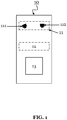
- FIG. 1 shows a schematic view of a holographic imaging device 10 for generating a 3D image of an object, according to an embodiment of the invention.
- the holographic imaging device 10 comprises an imaging unit 11 comprising at least two light sources 111, 112.
- the imaging unit 11 is configured to illuminate an object 12 by emitting at least two light beams with the at least two light sources 111, 112, wherein a first light beam has a first wave-vector and a first wavelength and a second light beam has a second wave-vector that is different from the first wave-vector and a second wavelength that is different from the first wavelength.
- the holographic imaging device 10 may thus use an illumination method entailing multiple light beams with both angular and spectral plurality.
- the holographic imaging device 10 further comprises a processing unit 13 configured to obtain at least two holograms of the object 12 by controlling the imaging unit 11 to sequentially illuminate the object 12 with respectively the first light beam and the second light beam, construct at least two 2D image slices based on the at least two holograms, wherein each 2D image slice is constructed at a determined depth within the object volume, and generate a 3D image of the object 12 based on a combination of the 2D image slices.
- a processing unit 13 configured to obtain at least two holograms of the object 12 by controlling the imaging unit 11 to sequentially illuminate the object 12 with respectively the first light beam and the second light beam, construct at least two 2D image slices based on the at least two holograms, wherein each 2D image slice is constructed at a determined depth within the object volume, and generate a 3D image of the object 12 based on a combination of the 2D image slices.
- the holographic imaging device 10 may comprise a circuitry.
- the circuitry may comprise hardware (e.g., the imaging unit, a display, the processing unit (e.g., a Central Processing Unit (CPU)), a memory, etc.) and software (e.g., a program for constructing 2D image slices, a program/algorithm for generating 3D image, etc.).
- hardware e.g., the imaging unit, a display, the processing unit (e.g., a Central Processing Unit (CPU)), a memory, etc.
- software e.g., a program for constructing 2D image slices, a program/algorithm for generating 3D image, etc.
- the processing unit 12 may obtain the holograms. Moreover, the holograms recorded with such plurality may be reconstructed digitally based on the 2D diffraction theory and image processing algorithms.
- the holographic imaging device 10 may use the differences in recorded holograms generated by the angular and spectral plurality in an iterative procedure in which at each step the in-focus signal is identified and cleaned from the out-of-focus signal.
- the holographic imaging device 10 e.g., its processing unit 13
- the holographic imaging device 10 may combine the 2D image slices to obtain a 3D image (a 3D representation of the sample).
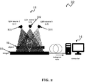
- FIG. 2 is another schematic view of the holographic imaging device 10, according to an embodiment of the invention.
- the imaging unit 11 of the holographic imaging device 10 comprises three light sources including the "light source 1" 111 illuminating with the first wavelength ⁇ 1, the "light source 2" 112 illuminating with the second wavelength ⁇ 2, the "light source 3" 211 illuminating with the third wavelength ⁇ 3.
- the holographic imaging device 10 further comprises an imager 22 and the processing unit 14 (e.g., a computer).
- the processing unit 14 e.g., a computer
- the holographic imaging device 10 of FIG. 2 configured to illuminate multiple light beams with wave-vector (angular) and wavelength (spectral) plurality.
- three light beams are generated from three light sources 111, 112, 211 which are in different location with respect to the origin of the imaging system.
- each of the light sources 111, 112, 211 emits a corresponding light beam with a different wavelength.
- the pluralities of wave-vector and wavelength may lead (e.g., may be used) to suppressing two distinct sources of out-of-focus plane signals.
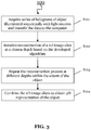
- FIG. 3 is a flow chart of a method 100 for generating a 3D image of an object.
- the method 100 may be performed by the holographic imaging device 10 (of FIG. 1 and/or FIG. 2 ).
- the method 100 is discussed exemplarily being performed by the holographic imaging device 10 of FIG. 2 .
- the holographic imaging device 10 acquires series of holograms of object 12 illuminated sequentially with light sources 111, 112, 211 and transfer the data to the computer 14.
- the holographic imaging device 10 performs iterative reconstruction of a 2D image slice at a chosen depth based on the developed algorithm.
- the holographic imaging device 10 repeats the reconstruction process at different depths within the extent of the object 12.
- the holographic imaging device 10 combines the 2D image slices to obtain a 3D representation of the object 12.
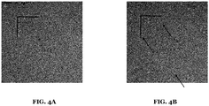
- FIG. 4A and FIG. 4B show an example of recorded holograms (three holograms in sequence provided as a video) of a sample obtained by the holographic imaging device 10 with three light sources 111, 112, 211 with different wavelengths but the same wave-vector directions.
- the main image features on the hologram (the interference patterns) look very similar to each other except that the fine fringes on the interference pattern are observed to shift with different wavelength of illumination.
- the differences between the holograms are observed, since the optical path between the objects 12 in the sample and the imager 22 changes with different illumination beams despite the fixed physical distance.
- the difference in the optical paths can result in different ghost images of the same object 12 in the reconstructed hologram.
- the plurality in illumination wavelength (illuminated by the holographic imaging device 10) results in a distinguishable signature for the out-of-focus plane signal originating from the ghost image of the object 12.
- the holographic imaging device 10 is further configured to provide the plurality of wave-vectors of light beams to overcome the out-of-focus plane signals.
- FIG. 4B shows an example of recorded holograms of the sample with three light sources 111, 112, 211 with different wave-vectors (three holograms in sequence provided as a video in FIG.4B ).
- the features in the holograms shift laterally according to the wave-vector of the illumination beam.
- the strength of the relative shift between the holograms depends on the distance of the objects 12 from the image sensor 22. Closer the object 12 to the imager 22, the smaller the shift with varying wave-vector.
- the arrows in FIG. 4B indicate to three distinct features in the hologram sequence.
- the plurality in illumination wave-vector results in a distinguishable signature for the signals originating from objects located at different depths.
- the strength of the distinguishable signature is a function of illumination beam angle and the pixel size of the imager 22. Larger the angle of the illumination and smaller the imager pixel size, larger the signature distinguishing two objects closely spaced slices.
- the holographic imaging device 10 provides both types of illumination plurality (wave-vector and wavelength) in creating distinguishable signatures to effectively suppress different types of out-of-focus plane signals in the reconstructed images.
- the next step is digitally processing them to obtain 2D image slices of the object at different depths with suppressed out-of-focus signals.
- the steps of image reconstruction and processing may be split into three steps as follow.
- the goal of the first step is to find out the wave-vectors of the light sources using a sample suitable for the purpose. This may be a practical calibration procedure before taking a measurement of sample. For example, in some embodiments, the wave-vectors must be accurately known as the values are critical for the image reconstruction steps following it.
- FIG. 5 shows a schematic view of a diagram 50 for determining the first wave-vector and the second wave-vector and obtaining a phase-retrieved hologram.
- the holographic imaging device 10 may determine the first wave-vector and the second wave-vector and may calibrate the position of the light sources 111, 112, 113.
- the holographic imaging device 10 may further obtains the phase-retrieved holograms.
- the holograms acquired with the imager 22 may contain only the intensity of the hologram and the phase component may be lost.
- the holographic imaging device 10 may apply a phase retrieval procedure to estimate the phase of holograms using the plurality of the wavelengths of illumination. It is important to note that the second phase is repeated for all the holograms acquired from the imager. Therefore, a phase estimation is done on all holograms.
- the output of the second step is the three phase-retrieved holograms and it will be passed to step three.
- the reconstruction of these holograms in the next step may result in a cleaned ghost image signal.
- the object image reconstruction may be performed by using the phase retrieved holograms corresponding to three different wave-vector illumination beams.
- the first process is to reconstruct three 2D image slices within the object volume from the phase retrieved holograms.
- the holographic imaging device 10 may use a 2D diffraction theory based on field propagation such as angular spectrum, etc.
- the reconstructed slices are free-from out-of-focus signal originating from the ghost image but not the ones (signals) generated from the objects (another object than the desired object) located near the slice depth.
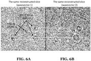
- An example of such slices is shown in FIG. 6A and FIG. 6B . These two images reveal that in-focus signals overlap spatially in two images while the out-of-focus signals are shifted relatively.
- the holographic imaging device 10 may suppress the out-of-focus signals using the three reconstructed slices and a noise removal algorithm designed to minimize the differences between the reconstructed slices from three different holograms.
- the noise removal algorithm succeeds to reject out-of-focus plane signal since only the in-focus signal overlaps in all different slices while out-of-focus signal is spatially dislocated among the three slices.
- the holographic imaging device 10 may use different noise removal procedures. For example, the simplest approach may be averaging the three reconstructed slices as the overlapping in-focus signal will be enhanced while non-overlapping out-of-focus signal will be averaged out. More advanced approaches may be used to suppress the unwanted signals.
- One of such approaches is formulating the finding in-focus signal as an inverse problem and minimizing the error using regularization in an iterative optimization algorithm. It is common to use L1, L2 and TV norms in image processing to solve inverse problems depending on the nature of the problem. Such an approach can be used to minimize the error occurring in three distinct reconstructed slices enabled by the different wave-vectors.
- the holographic imaging device 10 may process the slices at other depths in a similar procedure as explained above. Once all the slices in the sample volume are processed, the slices can be stacked into a 3D data representation. The holographic imaging device 10 may enable enhanced depth resolution to create true 3D imaging of complex samples.
- FIG. 7A-B shows an image of planar samples of metal lines on a substrate obtained by, a conventional device ( FIG. 7A ) and the holographic imaging device 10 of the invention ( FIG. 7B ).
- the holographic imaging device 10 removes the ghost image related out-of-focus signal.
- FIG. 8A-B shows an image slice (slice #1) from a sample including micron beads dispersed in 500 micron thick gel obtained by, a conventional device ( FIG. 8A ) and the holographic imaging device of the invention ( FIG. 8B ).
- the holographic imaging device 10 removes (from slice #1) the out-of-focus plane signals.
- FIG. 9A-B shows another image slice (slice #2) from the sample of FIG. 8A-B obtained by, a conventional device ( FIG. 9A ) and the holographic imaging device of the invention ( FIG. 9B ).
- the holographic imaging device 10 removes (from slice #2) the out-of-focus plane signals.
- the holographic imaging device 10 effectively suppresses the out-of-focus signal originating from beads in other depths.
- FIG. 10 shows a method 200 according to an embodiment of the invention for a holographic imaging device 10.
- the method 200 may be carried out by the holographic imaging device 10, as it is described above.
- the method 200 comprises a step S201 of illuminating, by an imaging unit 11 comprising at least two light sources 111, 112, an object 12 by emitting at least two light beams with the at least two light sources, wherein a first light beam has a first wave-vector and a first wavelength and a second light beam has a second wave-vector that is different from the first wave-vector and a second wavelength that is different from the first wavelength.
- the method 200 further comprises a step S202 of obtaining, by a processing unit 13, at least two holograms of the object 12 by controlling the imaging unit 11 to sequentially illuminate the object 12 with respectively the first light beam and the second light beam.
- the method 200 further comprises a step S203 of constructing, by the processing unit 13, at least two 2D image slices based on the at least two holograms, wherein each 2D image slice is constructed at a determined depth within the object volume.
- the method 200 further comprises a step S204 of generating, by the processing unit 13, a 3D image of the object 12 based on a combination of the 2D image slices.
Landscapes
- Engineering & Computer Science (AREA)
- Physics & Mathematics (AREA)
- General Physics & Mathematics (AREA)
- Theoretical Computer Science (AREA)
- Computer Vision & Pattern Recognition (AREA)
- Computing Systems (AREA)
- Quality & Reliability (AREA)
- Multimedia (AREA)
- Signal Processing (AREA)
- Holo Graphy (AREA)
Abstract
Description
- The present invention relates to a holographic imaging device and to a method for generating a three-dimensional (3D) image of an object, based on obtaining holograms of the object using at least two light beams. In particular, the holographic imaging device and the method may improve axial resolution of conventional inline holographic imaging. The holographic imaging device and the method may be applicable for microscopic imaging of volume samples used for quantitative image analysis.
- Conventional lens-free imaging (e.g., based on inline holography) is a powerful microscopic imaging method, which does not require any lenses or other optical or mechanical components to form an image. While it has many advantages, for example hardware simplicity, one of its known limitations is its weak signal localization in 3D space, and thus it has been popular for imaging planar (i.e., two dimensional (2D)) sparse samples localized in a surface parallel to the image sensor.
- Lens-free imaging on samples with a 3D structure is challenging, due to two distinct reasons. First, this imaging method has a limited depth of resolution, due to low "effective NA" or "missing cone in k-space" of the system. This limitation combined with the holographic nature of the image recording, i.e., the samples along the beam path are recorded in the optical image regardless of their depth, makes the imaging of 3D samples challenging. The signals from different depths interfere and are not localized. Second, the loss of phase information by hologram recording leads to a problem of twin image noise. Twin images arise because the image reconstruction process yields identical solutions for the object and the imaginary mirror object located at the same distance to imager but with negative sign. This effect in practice leads to a merging of the original object image with its defocused image appearing together in the reconstructed image. The two effects combined create a considerable problem for applying lens-free imaging to 3D samples.
- The two effects are visually explained in the diagram 110 of
FIG. 11 . The diagram 110 illustrates a sample consisting of multiple 10-µm-sized beads randomly distributed in a volume. The hologram obtained from these beads is reconstructed at a certain slice in the volume. Even though the in-focus beads can be identified visually in the slice reconstruction, the signal originating from the beads from a different slice strongly interferes with the signal originating from the beads in the slice. Furthermore, the in-focus beads signal is corrupted with the beads signal originating from the "ghost beads" located in a far distance. - In view of the above-mentioned disadvantages, embodiments of the present invention aim to improve axial resolution of conventional inline holographic imaging. An objective is in particular to provide a holographic imaging device and a method, which enable 3D representation of objects. To this end, a main goal is out-of-focus plane signal suppression in a 2D image generated by a lens-free system.
- The objective is achieved by the embodiments of the invention provided in the enclosed independent claims. Advantageous implementations of these embodiments are defined in the dependent claims.
- In particular, a distinguishable signature for the out-of-focus objects may be determined, and then the out-of-focus signals may be suppressed while preserving the in-focus signal.
- The main advantages of the embodiments of the invention may be summarized as follows:
- Lower hardware complexity compared to, e.g., conventional tomography methods.
- Lower costs, higher reliability, easy to maintain and service the device.
- Lower computational complexity compared to deconvolution/topography methods, which may provide faster results and lower power consumption.
- A first aspect of the invention provides a holographic imaging device comprising an imaging unit comprising at least two light sources, wherein the imaging unit is configured to illuminate an object by emitting at least two light beams with the at least two light sources, wherein a first light beam has a first wave-vector and a first wavelength and a second light beam has a second wave-vector that is different from the first wave-vector and a second wavelength that is different from the first wavelength; and a processing unit configured to obtain at least two holograms of the object by controlling the imaging unit to sequentially illuminate the object with respectively the first light beam and the second light beam, construct at least two two-dimensional (2D) image slices based on the at least two holograms, wherein each 2D image slice is constructed at a determined depth within the object volume, and generate a three-dimensional (3D) image of the object based on a combination of the 2D image slices.
- The holographic imaging device of the first aspect may be based on a lens-free system, which may remove out-of-focus plane signals in the constructed 2D image slices. In particular, the holographic imaging device may provide techniques to create a distinguishable signature for the out-of-focus objects, and then remove (i.e., suppress) the out-of-focus signals while preserving the in-focus signal.
- More specifically, the holographic imaging device can use the imaging unit and an illumination method entailing multiple light beams with a both angular and spectral plurality. The holograms recorded with such plurality may further be reconstructed digitally based on the 2D diffraction theory and image processing algorithms. For example, the processing unit of the holographic imaging device may provide an algorithm, which may use the differences in recorded holograms generated by the angular and spectral plurality in an iterative procedure, in which at each step the in-focus signals are identified and cleaned from the out-of-focus signals, until the algorithm converges to the desired result. This process may be repeated several times at different depths (e.g., depth within the object). The depth within the object may be, for example, a distance from a predefined position, e.g., front to the back of the object, a horizontal measurement of the object's protrusion into space, a measurement perpendicular to the object's width, etc.
- The holographic imaging device (e.g., the processing unit or the algorithm provided in the processing unit) may combine the processed slices for obtaining a three-dimensional representation of the sample.
- In an implementation of the holographic imaging device, the first wave-vector and/or the second wave-vector are predetermined based on relative positions of the at least two light sources.
- In particular, the holographic imaging device may also work with lower incidence angles, resulting in a compact (and practical for implementation in instruments) light source as well as a larger field of view due to lower area of "non-overlap" between illumination cones compared to the conventional topography techniques.
- In some embodiments of the invention, a calibration of the holographic imaging device may be required. For example, the holographic imaging device may be sensitive to errors in the light source positions. The first wave-vector and/or the second wave-vector may be determined and the holographic imaging device may be calibrated.
- In a further implementation of the holographic imaging device, the processing unit is further configured to obtain at least two phase-retrieved holograms based on estimating a phase of each of the at least two holograms.
- This provides the advantage that the out-of-focus ghost image of the object may be removed.
- In a further implementation of the holographic imaging device, the phase of a first hologram is estimated based on performing an iterative phase retrieval procedure by using a second hologram obtained with a different wavelength of illumination.
- In a further implementation of the holographic imaging device, the processing unit is further configured to determine a signature for an out-of-focus plane signal originating from a ghost image of the object, based on a comparison of the at least two phase-retrieved holograms, and remove, from the at least two phase-retrieved holograms, at least one out-of- focus plane signal originating from the ghost image of the object.
- In particular, since the optical path between the object and, for example, an imager of the holographic imaging device changes for different illumination beams, this may result in a difference between the obtained holograms. Moreover, the changes in the optical paths may be used for determining (e.g., removing) different ghost images of the same object in the reconstructed hologram.
- In a further implementation of the holographic imaging device, constructing the at least two 2D image slices comprises obtaining, based on the at least two phase-retrieved holograms, at least two 2D image slices each for a respective depth within the object volume.
- In a further implementation of the holographic imaging device, the processing unit is further configured to compare the at least two 2D image slices, identify spatially overlapped signals in the at least two 2D image slices indicating in-focus signals of the object, and identify substantially shifted signals in the at least two 2D image slices indicating out-of-focus signals originating from other real objects located in out-of-focus-planes.
- In a further implementation of the holographic imaging device, the processing unit is further configured to remove, from the at least two 2D image slices, at least one identified out-of-focus plane signal originating from another real object, and perform a noise removal procedure for minimizing a difference between the at least two 2D image slices.
- This provides the advantage that the out-of-focus real object signals (for example, of another real object, which may be located at a different depth) may be determined and may further be removed.
- In a further implementation of the holographic imaging device, performing the noise removal procedure comprises removing out-of-focus plane signals that are spatially dislocated among the at least two 2D image slices, and/or determining and maintaining in-focus signals that are overlapped in the at least two 2D image slices.
- In a further implementation of the holographic imaging device, the processing unit is further configured to stack the constructed at least two 2D image slices, for generating the 3D image of the object, wherein each 2D image slice is used at its determined depth within the object volume.
- This provides the advantage that the generated 3D image of the object may be provided. Moreover, for example, the exact volumes of the objects in the sample may be determined, which may enable quantitative image analysis. Such quantitative image analysis may have application in volumetric imaging of biological samples, for example, bacteria, cells or other samples in suspension, colony, reactor etc. This is important, for example, to determine the growth rate, motility or division behavior of the cells, bacteria, etc., under different environmental conditions.
- Another application of the holographic imaging device may be in air quality monitoring, water quality monitoring, pollen monitoring, industrial monitoring of fluids or gases, and in principle any imaging application requiring volumetric imaging capability at high lateral and axial resolution implemented as a simple, miniature and cost effective imaging setup.
- In a further implementation of the holographic imaging device, the imaging unit is further comprising at least one imager, and wherein each light source is arranged at a predefined position from the at least one imager.
- In a further implementation of the holographic imaging device, the at least one imager is based on a Complementary Metal Oxide Semiconductor (CMOS) image sensor.
- In a further implementation of the holographic imaging device, the first wavelength and/or the second wavelength are within a range of 300 nm to 900 nm.
- In particular, the first wavelength and/or the second wavelength may be within visible spectrum.
- A second aspect of the invention provides a method for a holographic imaging device, the method comprises illuminating, by an imaging unit comprising at least two light sources, an object by emitting at least two light beams with the at least two light sources, wherein a first light beam has a first wave-vector and a first wavelength and a second light beam has a second wave-vector that is different from the first wave-vector and a second wavelength that is different from the first wavelength, obtaining, by a processing unit, at least two holograms of the object by controlling the imaging unit to sequentially illuminate the object with respectively the first light beam and the second light beam, constructing, by the processing unit, at least two two-dimensional (2D) image slices based on the at least two holograms, wherein each 2D image slice is constructed at a determined depth within the object volume, and generating, by the processing unit, a three-dimensional (3D) image of the object based on a combination of the 2D image slices.
- The method of the second aspect can be further developed according to the foregoing implementations of the holographic imaging device of the first aspect. The method of the second aspect thus achieves the same advantages as the holographic imaging device of the first aspect and its implementations.
- A third aspect of the invention provides a computer program which, when executed by a computer, causes the method of the second aspect to be performed.
- In some embodiments, the computer program may be provided on a non-transitory computer-readable recording medium.
- The above described aspects and implementations are explained in the following description of embodiments with respect to the enclosed drawings:
- FIG. 1
- shows a schematic view of a holographic imaging device for generating a 3D image of an object, according to an embodiment of the invention;
- FIG. 2
- shows another schematic view of the holographic imaging device, according to an embodiment of the invention;
- FIG. 3
- shows a flow chart of a method for generating a 3D image of an object;
- FIG. 4A-B
- shows different obtained holograms;
- FIG. 5
- shows a schematic view of a diagram illustrating obtaining a phase-retrieved hologram;
- FIG. 6A-B
- shows exemplarily obtained holograms with the first wave-vector (
FIG. 6A ) and the second wave-vector (FIG. 6B ); - FIG. 7A-B
- shows an image of planar samples obtained by, a conventional device (
FIG. 7A ) and the holographic imaging device of the invention (FIG. 7B ); - FIG. 8A-B
- shows an image slice from a sample including micron beads dispersed in 500 micron thick obtained by, a conventional device (
FIG. 8A ) and the holographic imaging device of the invention (FIG. 8B ); - FIG. 9A-B
- shows another image slice from the sample of
FIG. 8A-B obtained by, a conventional device (FIG. 9A ) and the holographic imaging device of the invention (FIG. 9B ); - FIG. 10
- shows a method for the holographic imaging device, according to an embodiment of the invention; and
- FIG. 11
- shows problems of out-of-focus signals in 2D image slices obtained by a conventional holographic imaging device.
-
FIG. 1 shows a schematic view of aholographic imaging device 10 for generating a 3D image of an object, according to an embodiment of the invention. - The
holographic imaging device 10 comprises animaging unit 11 comprising at least twolight sources imaging unit 11 is configured to illuminate anobject 12 by emitting at least two light beams with the at least twolight sources - The
holographic imaging device 10 may thus use an illumination method entailing multiple light beams with both angular and spectral plurality. - The
holographic imaging device 10 further comprises aprocessing unit 13 configured to obtain at least two holograms of theobject 12 by controlling theimaging unit 11 to sequentially illuminate theobject 12 with respectively the first light beam and the second light beam, construct at least two 2D image slices based on the at least two holograms, wherein each 2D image slice is constructed at a determined depth within the object volume, and generate a 3D image of theobject 12 based on a combination of the 2D image slices. - The
holographic imaging device 10 may comprise a circuitry. The circuitry may comprise hardware (e.g., the imaging unit, a display, the processing unit (e.g., a Central Processing Unit (CPU)), a memory, etc.) and software (e.g., a program for constructing 2D image slices, a program/algorithm for generating 3D image, etc.). - For example, the
processing unit 12 may obtain the holograms. Moreover, the holograms recorded with such plurality may be reconstructed digitally based on the 2D diffraction theory and image processing algorithms. - The holographic imaging device 10 (e.g., its
processing unit 13, or a program such as an algorithm running on the processing unit 13) may use the differences in recorded holograms generated by the angular and spectral plurality in an iterative procedure in which at each step the in-focus signal is identified and cleaned from the out-of-focus signal. The holographic imaging device 10 (e.g., its processing unit 13) may repeat this procedure several times at different depths. - Moreover, the holographic imaging device 10 (e.g., its processing unit 13) may combine the 2D image slices to obtain a 3D image (a 3D representation of the sample).
- Reference is made to
FIG. 2 , which is another schematic view of theholographic imaging device 10, according to an embodiment of the invention. - The
imaging unit 11 of theholographic imaging device 10 comprises three light sources including the "light source 1" 111 illuminating with the first wavelength λ1, the "light source 2" 112 illuminating with the second wavelength λ2, the "light source 3" 211 illuminating with the third wavelength λ3. - The
holographic imaging device 10 further comprises animager 22 and the processing unit 14 (e.g., a computer). - The
holographic imaging device 10 ofFIG. 2 configured to illuminate multiple light beams with wave-vector (angular) and wavelength (spectral) plurality. For example, three light beams are generated from threelight sources light sources - Reference is made to
FIG. 3 , which is a flow chart of amethod 100 for generating a 3D image of an object. Themethod 100 may be performed by the holographic imaging device 10 (ofFIG. 1 and/orFIG. 2 ). - Without limiting the present disclosure, in the following, the
method 100 is discussed exemplarily being performed by theholographic imaging device 10 ofFIG. 2 . - At step S101, the
holographic imaging device 10 acquires series of holograms ofobject 12 illuminated sequentially withlight sources computer 14. - At step S102, the
holographic imaging device 10 performs iterative reconstruction of a 2D image slice at a chosen depth based on the developed algorithm. - At step S103, the
holographic imaging device 10 repeats the reconstruction process at different depths within the extent of theobject 12. - At step S104, the
holographic imaging device 10 combines the 2D image slices to obtain a 3D representation of theobject 12. - Reference is made to
FIG. 4A and FIG. 4B , in whichFIG 4A shows an example of recorded holograms (three holograms in sequence provided as a video) of a sample obtained by theholographic imaging device 10 with threelight sources - The differences between the holograms are observed, since the optical path between the
objects 12 in the sample and theimager 22 changes with different illumination beams despite the fixed physical distance. The difference in the optical paths can result in different ghost images of thesame object 12 in the reconstructed hologram. Thus, the plurality in illumination wavelength (illuminated by the holographic imaging device 10) results in a distinguishable signature for the out-of-focus plane signal originating from the ghost image of theobject 12. - The plurality of wavelengths in practice may be within a range of 300 nm to 900 nm (for example, it may be limited within visible spectrum λ= 400 nm - 700 nm, in which CMOS image sensors are typically sensitive and optical properties of objects do not vary widely). While such range is sufficient to create distinguishable signatures between the
object 12 and its ghost in practice (typically located hundreds of microns away from the object in depth), this approach may not be useful for signals originating from other real objects located in out-of-focus planes that are relatively close to the in-focus plane slice. - The
holographic imaging device 10 is further configured to provide the plurality of wave-vectors of light beams to overcome the out-of-focus plane signals.FIG. 4B shows an example of recorded holograms of the sample with threelight sources FIG.4B ). Differently fromFIG. 4A , the features in the holograms shift laterally according to the wave-vector of the illumination beam. The strength of the relative shift between the holograms depends on the distance of theobjects 12 from theimage sensor 22. Closer theobject 12 to theimager 22, the smaller the shift with varying wave-vector. The arrows inFIG. 4B indicate to three distinct features in the hologram sequence. These three features originate from objects located three different depths. The feature in the bottom side of the hologram hardly shifts while the other two features shift visibly in the hologram sequence. A careful inspection suggests that the L-shaped feature shifts less than the circular one indicating that the L-shaped object is closer to the imager in distance. Thus, the plurality in illumination wave-vector (provided by the holographic imaging device 10) results in a distinguishable signature for the signals originating from objects located at different depths. The strength of the distinguishable signature is a function of illumination beam angle and the pixel size of theimager 22. Larger the angle of the illumination and smaller the imager pixel size, larger the signature distinguishing two objects closely spaced slices. - It is important to note that the plurality in illumination wave-vector alone may not be useful in creating a distinguishable signature of the out-of-focus plane originating from the ghost object image, since the ghost image shifts together with the object image and both always overlap with each other regardless of the wave-vector direction. Therefore, the
holographic imaging device 10 provides both types of illumination plurality (wave-vector and wavelength) in creating distinguishable signatures to effectively suppress different types of out-of-focus plane signals in the reconstructed images. At next, a discussion provided for processing the multiple holograms to achieve the out-of-focus signal suppression. - In the following, description of the 2D image construction and generating the 3D image is provided.
- Once the
holographic imaging device 10 obtains the multiple holograms (e.g., acquired with the mentioned illumination method), the next step is digitally processing them to obtain 2D image slices of the object at different depths with suppressed out-of-focus signals. The steps of image reconstruction and processing may be split into three steps as follow. - The goal of the first step is to find out the wave-vectors of the light sources using a sample suitable for the purpose. This may be a practical calibration procedure before taking a measurement of sample. For example, in some embodiments, the wave-vectors must be accurately known as the values are critical for the image reconstruction steps following it.
- Reference is made to
FIG. 5 , which shows a schematic view of a diagram 50 for determining the first wave-vector and the second wave-vector and obtaining a phase-retrieved hologram. - Initially, the
holographic imaging device 10 may determine the first wave-vector and the second wave-vector and may calibrate the position of thelight sources - ▪ The goals of the first step may be:
- ▪ Determining the relative source positions (x, y).
- ▪ Converting the source positions into wave-vectors with a known source displacement of z.
- ▪ The performed operations may be summarized as follow:
- ▪ Estimating the relative shift of the holograms with sub-pixel accuracy. For example, an algorithm may be used which may be based on a fast implementation of cross correlation between the images.
- ▪ Reconstructing firstly the holograms in focus with an "initial guess of the positions".
- ▪ Using the reconstructed object images for determining the sharp features and obtaining a better accuracy for registration.
- ▪ Applying an image registration procedure for the reconstructed images and determining the error in the initial guess.
- ▪ Finding accurate x, y per source.
- ▪ Determining the wave-vectors.
- In the second step, the
holographic imaging device 10 may further obtains the phase-retrieved holograms. - For instance, the holograms acquired with the
imager 22 may contain only the intensity of the hologram and the phase component may be lost. Theholographic imaging device 10 may apply a phase retrieval procedure to estimate the phase of holograms using the plurality of the wavelengths of illumination. It is important to note that the second phase is repeated for all the holograms acquired from the imager. Therefore, a phase estimation is done on all holograms. The output of the second step is the three phase-retrieved holograms and it will be passed to step three. - ▪ The goals of the second step may be:
- ▪ Phase retrieval for the holograms using the wavelength plurality.
- ▪ Removal of out of focus plane ghost image signal.
- ▪ The performed operations may be summarized as follow:
- ▪ Phase retrieval may be based on propagating complex valued holograms and replacing the phases at even steps (steps of a single iteration drawn for H1 on the left).
- ▪ Choosing a slice (zobj) in the object volume for reconstruction.
- ▪ After N iterations, repeating step one for obtaining ghost-free image of the object with wavevector-i.
- ▪ Repeating the process for all the holograms (e.g., H2 and H3).
- ▪ Obtaining as final output, three holograms with retrieved phases.
- The reconstruction of these holograms in the next step may result in a cleaned ghost image signal.
- At the third step, the object image reconstruction may be performed by using the phase retrieved holograms corresponding to three different wave-vector illumination beams. The first process is to reconstruct three 2D image slices within the object volume from the phase retrieved holograms. For example, the
holographic imaging device 10 may use a 2D diffraction theory based on field propagation such as angular spectrum, etc. Note that the reconstructed slices are free-from out-of-focus signal originating from the ghost image but not the ones (signals) generated from the objects (another object than the desired object) located near the slice depth. An example of such slices is shown inFIG. 6A and FIG. 6B . These two images reveal that in-focus signals overlap spatially in two images while the out-of-focus signals are shifted relatively. - Once the reconstructed slices are obtained, at next the
holographic imaging device 10 may suppress the out-of-focus signals using the three reconstructed slices and a noise removal algorithm designed to minimize the differences between the reconstructed slices from three different holograms. The noise removal algorithm succeeds to reject out-of-focus plane signal since only the in-focus signal overlaps in all different slices while out-of-focus signal is spatially dislocated among the three slices. - The
holographic imaging device 10 may use different noise removal procedures. For example, the simplest approach may be averaging the three reconstructed slices as the overlapping in-focus signal will be enhanced while non-overlapping out-of-focus signal will be averaged out. More advanced approaches may be used to suppress the unwanted signals. One of such approaches is formulating the finding in-focus signal as an inverse problem and minimizing the error using regularization in an iterative optimization algorithm. It is common to use L1, L2 and TV norms in image processing to solve inverse problems depending on the nature of the problem. Such an approach can be used to minimize the error occurring in three distinct reconstructed slices enabled by the different wave-vectors. - The
holographic imaging device 10 may process the slices at other depths in a similar procedure as explained above. Once all the slices in the sample volume are processed, the slices can be stacked into a 3D data representation. Theholographic imaging device 10 may enable enhanced depth resolution to create true 3D imaging of complex samples. - Experimental validation of the proposed invention is done, and some initial results (obtained by the holographic imaging device 10) are presented in the following, without limiting the present disclosure.
-
FIG. 7A-B shows an image of planar samples of metal lines on a substrate obtained by, a conventional device (FIG. 7A ) and theholographic imaging device 10 of the invention (FIG. 7B ). - As it can be derived from
FIG.7B , theholographic imaging device 10 removes the ghost image related out-of-focus signal. -
FIG. 8A-B shows an image slice (slice #1) from a sample including micron beads dispersed in 500 micron thick gel obtained by, a conventional device (FIG. 8A ) and the holographic imaging device of the invention (FIG. 8B ). - As it can be derived from
FIG.8B , theholographic imaging device 10 removes (from slice #1) the out-of-focus plane signals. -
FIG. 9A-B shows another image slice (slice #2) from the sample ofFIG. 8A-B obtained by, a conventional device (FIG. 9A ) and the holographic imaging device of the invention (FIG. 9B ). - As it can be derived from
FIG.9B , theholographic imaging device 10 removes (from slice #2) the out-of-focus plane signals. - As it can be derived from the two image slices (e.g.,
FIG. 8B andFIG.9B ) that are obtained from the sample containing imicron sized beads distributed in a 3D volume, theholographic imaging device 10 effectively suppresses the out-of-focus signal originating from beads in other depths. -
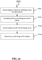
FIG. 10 shows amethod 200 according to an embodiment of the invention for aholographic imaging device 10. Themethod 200 may be carried out by theholographic imaging device 10, as it is described above. - The
method 200 comprises a step S201 of illuminating, by animaging unit 11 comprising at least twolight sources object 12 by emitting at least two light beams with the at least two light sources, wherein a first light beam has a first wave-vector and a first wavelength and a second light beam has a second wave-vector that is different from the first wave-vector and a second wavelength that is different from the first wavelength. - The
method 200 further comprises a step S202 of obtaining, by aprocessing unit 13, at least two holograms of theobject 12 by controlling theimaging unit 11 to sequentially illuminate theobject 12 with respectively the first light beam and the second light beam. - The
method 200 further comprises a step S203 of constructing, by theprocessing unit 13, at least two 2D image slices based on the at least two holograms, wherein each 2D image slice is constructed at a determined depth within the object volume. - The
method 200 further comprises a step S204 of generating, by theprocessing unit 13, a 3D image of theobject 12 based on a combination of the 2D image slices.
Claims (15)
- A holographic imaging device (10) comprising:an imaging unit (11) comprising at least two light sources (111, 112), wherein the imaging unit (11) is configured to:- illuminate an object (12) by emitting at least two light beams with the at least two light sources (111, 112), wherein a first light beam has a first wave-vector and a first wavelength and a second light beam has a second wave-vector that is different from the first wave-vector and a second wavelength that is different from the first wavelength; anda processing unit (13) configured to:- obtain at least two holograms of the object (12) by controlling the imaging unit (11) to sequentially illuminate the object (12) with respectively the first light beam and the second light beam,construct at least two two-dimensional, 2D, image slices based on the at least two holograms, wherein each 2D image slice is constructed at a determined depth within the object volume, andgenerate a three-dimensional, 3D, image of the object (12) based on a combination of the 2D image slices.
- The holographic imaging device (10) according to claim 1, wherein:
the first wave-vector and/or the second wave-vector are predetermined based on relative positions of the at least two light sources (111, 112). - The holographic imaging device (10) according to claim 1 or 2, wherein the processing unit (13) is further configured to:
obtain at least two phase-retrieved holograms based on estimating a phase of each of the at least two holograms. - The holographic imaging device (10) according to claim 3, wherein:
the phase of a first hologram is estimated based on performing an iterative phase retrieval procedure by using a second hologram obtained with a different wavelength of illumination. - The holographic imaging device (10) according to claim 3 or 4, wherein the processing unit (13) is further configured to:determine a signature for an out-of-focus plane signal originating from a ghost image of the object (12), based on a comparison of the at least two phase-retrieved holograms, andremove, from the at least two phase-retrieved holograms, at least one out-of-focus plane signal originating from the ghost image of the object (12).
- The holographic imaging device (10) according claim 5, wherein:
constructing the at least two 2D image slices comprises obtaining, based on the at least two phase-retrieved holograms, at least two 2D image slices each for a respective depth within the object volume. - The holographic imaging device (10) according to claim 6, wherein the processing unit (13) is further configured to:compare the at least two 2D image slices,identify spatially overlapped signals in the at least two 2D image slices indicating in-focus signals of the object (12), andidentify substantially shifted signals in the at least two 2D image slices indicating out-of-focus signals originating from other real objects located in out-of-focus-planes.
- The holographic imaging device (10) according to claim 7, wherein the processing unit (13) is further configured to:remove, from the at least two 2D image slices, at least one identified out-of-focus plane signal originating from another real object, andperform a noise removal procedure for minimizing a difference between the at least two 2D image slices.
- The holographic imaging device (10) according to claim 8, wherein performing the noise removal procedure comprises:removing out-of-focus plane signals that are spatially dislocated among the at least two 2D image slices, and/ordetermining and maintaining in-focus signals that are overlapped in the at least two 2D image slices.
- The holographic imaging device (10) according to claim 8 or 9, wherein the processing unit (13) is further configured to:
stack the constructed at least two 2D image slices, for generating the 3D image of the object (12), wherein each 2D image slice is used at its determined depth within the object volume. - The holographic imaging device (10) according to one of the claims 1 to 10, wherein the imaging unit (11) is further comprising at least one imager (22), and wherein each light source (111, 112, 211) is arranged at a predefined position from the at least one imager (22).
- The holographic imaging device (10) according claim 11, wherein the at least one imager (22) is based on a Complementary Metal Oxide Semiconductor, CMOS, image sensor.
- The holographic imaging device (10) according to one of the claims 1 to 12, wherein:
the first wavelength and/or the second wavelength are within a range of 300 nm to 900 nm. - A method (200) for a holographic imaging device (10), the method (200) comprises:illuminating (S201), by an imaging unit (11) comprising at least two light sources (111, 112), an object (12) by emitting at least two light beams with the at least two light sources, wherein a first light beam has a first wave-vector and a first wavelength and a second light beam has a second wave-vector that is different from the first wave-vector and a second wavelength that is different from the first wavelength,obtaining (S202), by a processing unit (13), at least two holograms of the object (12) by controlling the imaging unit (11) to sequentially illuminate the object (12) with respectively the first light beam and the second light beam,constructing (S203), by the processing unit (13), at least two two-dimensional, 2D, image slices based on the at least two holograms, wherein each 2D image slice is constructed at a determined depth within the object volume, andgenerating (S204), by the processing unit (13), a three-dimensional, 3D, image of the object (12) based on a combination of the 2D image slices.
- A computer program which, when executed by a computer, causes the method (200) of claim 14 to be performed.
Priority Applications (2)
| Application Number | Priority Date | Filing Date | Title |
|---|---|---|---|
| EP19204031.9A EP3809208B1 (en) | 2019-10-18 | 2019-10-18 | Holographic imaging device and method |
| US17/033,123 US11487243B2 (en) | 2019-10-18 | 2020-09-25 | Holographic imaging device and method |
Applications Claiming Priority (1)
| Application Number | Priority Date | Filing Date | Title |
|---|---|---|---|
| EP19204031.9A EP3809208B1 (en) | 2019-10-18 | 2019-10-18 | Holographic imaging device and method |
Publications (2)
| Publication Number | Publication Date |
|---|---|
| EP3809208A1 true EP3809208A1 (en) | 2021-04-21 |
| EP3809208B1 EP3809208B1 (en) | 2025-12-10 |
Family
ID=68296083
Family Applications (1)
| Application Number | Title | Priority Date | Filing Date |
|---|---|---|---|
| EP19204031.9A Active EP3809208B1 (en) | 2019-10-18 | 2019-10-18 | Holographic imaging device and method |
Country Status (2)
| Country | Link |
|---|---|
| US (1) | US11487243B2 (en) |
| EP (1) | EP3809208B1 (en) |
Cited By (5)
| Publication number | Priority date | Publication date | Assignee | Title |
|---|---|---|---|---|
| US20210239844A1 (en) * | 2019-12-11 | 2021-08-05 | Swift Navigation, Inc. | System and method for validating gnss ambiguities |
| US12019163B2 (en) | 2022-09-12 | 2024-06-25 | Swift Navigation, Inc. | System and method for GNSS correction transmission |
| US12085654B2 (en) | 2021-07-24 | 2024-09-10 | Swift Navigation, Inc. | System and method for computing positioning protection levels |
| US12216211B2 (en) | 2021-12-10 | 2025-02-04 | Swift Navigation, Inc. | System and method for correcting satellite observations |
| US12498493B2 (en) | 2022-10-21 | 2025-12-16 | Swift Navigation, Inc. | System and method for distributed integrity monitoring |
Families Citing this family (2)
| Publication number | Priority date | Publication date | Assignee | Title |
|---|---|---|---|---|
| US12571718B2 (en) * | 2019-09-20 | 2026-03-10 | Kansas State University Research Foundation | Methods and apparatus for contactless orthographic imaging of aerosol particles |
| KR20240036751A (en) * | 2022-09-13 | 2024-03-21 | 삼성디스플레이 주식회사 | System and method for measuring depth of stereoscopic display |
Citations (2)
| Publication number | Priority date | Publication date | Assignee | Title |
|---|---|---|---|---|
| US20170153106A1 (en) * | 2011-01-06 | 2017-06-01 | The Regents Of The University Of California | Lens-free tomographic imaging devices and methods |
| US20180181062A1 (en) * | 2016-12-21 | 2018-06-28 | Imec Vzw | Apparatus and method for in-line holographic imaging |
Family Cites Families (1)
| Publication number | Priority date | Publication date | Assignee | Title |
|---|---|---|---|---|
| CN105158894A (en) | 2015-09-29 | 2015-12-16 | 南京理工大学 | Lens-free phase micro-tomography device based on color LED array illumination and image reconstruction method |
-
2019
- 2019-10-18 EP EP19204031.9A patent/EP3809208B1/en active Active
-
2020
- 2020-09-25 US US17/033,123 patent/US11487243B2/en active Active
Patent Citations (2)
| Publication number | Priority date | Publication date | Assignee | Title |
|---|---|---|---|---|
| US20170153106A1 (en) * | 2011-01-06 | 2017-06-01 | The Regents Of The University Of California | Lens-free tomographic imaging devices and methods |
| US20180181062A1 (en) * | 2016-12-21 | 2018-06-28 | Imec Vzw | Apparatus and method for in-line holographic imaging |
Non-Patent Citations (2)
| Title |
|---|
| MC ELHINNEY C P ET AL: "Focused image creation approaches for macroscopic objects encoded in digital holograms", PROCEEDINGS OF SPIE/ IS & T,, vol. 6994, 25 April 2008 (2008-04-25), pages 69940U/1, XP007905042, ISBN: 978-1-62841-730-2 * |
| WEI LUO ET AL: "Propagation phasor approach for holographic image reconstruction", SCIENTIFIC REPORTS, vol. 6, no. 1, 11 March 2016 (2016-03-11), XP055446743, DOI: 10.1038/srep22738 * |
Cited By (8)
| Publication number | Priority date | Publication date | Assignee | Title |
|---|---|---|---|---|
| US20210239844A1 (en) * | 2019-12-11 | 2021-08-05 | Swift Navigation, Inc. | System and method for validating gnss ambiguities |
| US11681050B2 (en) * | 2019-12-11 | 2023-06-20 | Swift Navigation, Inc. | System and method for validating GNSS ambiguities |
| US20230296786A1 (en) * | 2019-12-11 | 2023-09-21 | Swift Navigation, Inc. | System and method for validating gnss ambiguities |
| US12085654B2 (en) | 2021-07-24 | 2024-09-10 | Swift Navigation, Inc. | System and method for computing positioning protection levels |
| US12216211B2 (en) | 2021-12-10 | 2025-02-04 | Swift Navigation, Inc. | System and method for correcting satellite observations |
| US12019163B2 (en) | 2022-09-12 | 2024-06-25 | Swift Navigation, Inc. | System and method for GNSS correction transmission |
| US12442929B2 (en) | 2022-09-12 | 2025-10-14 | Swift Navigation, Inc. | System and method for GNSS correction transmission |
| US12498493B2 (en) | 2022-10-21 | 2025-12-16 | Swift Navigation, Inc. | System and method for distributed integrity monitoring |
Also Published As
| Publication number | Publication date |
|---|---|
| EP3809208B1 (en) | 2025-12-10 |
| US11487243B2 (en) | 2022-11-01 |
| US20210116863A1 (en) | 2021-04-22 |
Similar Documents
| Publication | Publication Date | Title |
|---|---|---|
| US11487243B2 (en) | Holographic imaging device and method | |
| CN110274877B (en) | A 3D spectral imaging system and method based on scattering medium | |
| US10684589B2 (en) | Apparatus and method for in-line holographic imaging | |
| EP3881137B1 (en) | System and method for transforming holographic microscopy images to microscopy images of various modalities | |
| EP3238135B1 (en) | Epi-illumination fourier ptychographic imaging for thick samples | |
| WO2013018024A1 (en) | Apparatus and method for quantitative phase tomography through linear scanning with coherent and non-coherent detection | |
| US9970891B2 (en) | System and method for phase retrieval in lensless imaging | |
| CN103822577A (en) | Single-pixel terahertz holographic imaging device and method | |
| JP6230598B2 (en) | Measuring device | |
| EP3252537A1 (en) | Digital holography recording device, digital holography playback device, digital holography recording method, and digital holography playback method | |
| JP6298049B2 (en) | Method and system for restoring optical properties of a diffractive object immersed in a liquid medium | |
| Fan et al. | Investigation of sparsity metrics for autofocusing in digital holographic microscopy | |
| TW202138866A (en) | Apparatus and method of estimating values from images | |
| KR20170037800A (en) | Method and system for detecting nano-scale defects on transparent objects | |
| WO2021003380A1 (en) | Calibration-free phase shifting procedure for self-interference holography | |
| EP3520022A1 (en) | Method for counting white blood cells in a sample | |
| KR102924417B1 (en) | Single-Shot Fourier Ptychographic Imaging Apparatus and Method Using Polarized Illumination | |
| US11480917B2 (en) | Method and apparatus for reconstructing three-dimensional image by using diffraction grating | |
| US20190121290A1 (en) | Digital holographic imaging apparatus | |
| Shin et al. | Frequency domain zero padding for accurate autofocusing based on digital holography | |
| Tuysuzoglu | Robust inversion and detection techniques for improved imaging performance | |
| FR2836575A1 (en) | Method for measuring object location by phase detection using a fixed observation system and a digital processor to process measurement data from a two dimensional periodic test marker fixed to the object being located | |
| EP2929343A1 (en) | Ultrasonic imaging device and method including filtering of artifacts resulting from interferences between reconstruction modes | |
| CN120491414A (en) | Light field resolution method and system | |
| Heimo | DENOISERS IN LENSLESS SINGLE-SHOT SUPER-RESOLUTION PHASE RE-TRIEVAL |
Legal Events
| Date | Code | Title | Description |
|---|---|---|---|
| PUAI | Public reference made under article 153(3) epc to a published international application that has entered the european phase |
Free format text: ORIGINAL CODE: 0009012 |
|
| STAA | Information on the status of an ep patent application or granted ep patent |
Free format text: STATUS: THE APPLICATION HAS BEEN PUBLISHED |
|
| AK | Designated contracting states |
Kind code of ref document: A1 Designated state(s): AL AT BE BG CH CY CZ DE DK EE ES FI FR GB GR HR HU IE IS IT LI LT LU LV MC MK MT NL NO PL PT RO RS SE SI SK SM TR |
|
| AX | Request for extension of the european patent |
Extension state: BA ME |
|
| STAA | Information on the status of an ep patent application or granted ep patent |
Free format text: STATUS: REQUEST FOR EXAMINATION WAS MADE |
|
| 17P | Request for examination filed |
Effective date: 20211014 |
|
| RBV | Designated contracting states (corrected) |
Designated state(s): AL AT BE BG CH CY CZ DE DK EE ES FI FR GB GR HR HU IE IS IT LI LT LU LV MC MK MT NL NO PL PT RO RS SE SI SK SM TR |
|
| STAA | Information on the status of an ep patent application or granted ep patent |
Free format text: STATUS: EXAMINATION IS IN PROGRESS |
|
| 17Q | First examination report despatched |
Effective date: 20230329 |
|
| GRAP | Despatch of communication of intention to grant a patent |
Free format text: ORIGINAL CODE: EPIDOSNIGR1 |
|
| STAA | Information on the status of an ep patent application or granted ep patent |
Free format text: STATUS: GRANT OF PATENT IS INTENDED |
|
| INTG | Intention to grant announced |
Effective date: 20250711 |
|
| RAP3 | Party data changed (applicant data changed or rights of an application transferred) |
Owner name: IMEC VZW |
|
| P01 | Opt-out of the competence of the unified patent court (upc) registered |
Free format text: CASE NUMBER: UPC_APP_0489_3809208/2025 Effective date: 20250717 |
|
| GRAS | Grant fee paid |
Free format text: ORIGINAL CODE: EPIDOSNIGR3 |
|
| GRAA | (expected) grant |
Free format text: ORIGINAL CODE: 0009210 |
|
| STAA | Information on the status of an ep patent application or granted ep patent |
Free format text: STATUS: THE PATENT HAS BEEN GRANTED |
|
| AK | Designated contracting states |
Kind code of ref document: B1 Designated state(s): AL AT BE BG CH CY CZ DE DK EE ES FI FR GB GR HR HU IE IS IT LI LT LU LV MC MK MT NL NO PL PT RO RS SE SI SK SM TR |
|
| REG | Reference to a national code |
Ref country code: CH Ref legal event code: F10 Free format text: ST27 STATUS EVENT CODE: U-0-0-F10-F00 (AS PROVIDED BY THE NATIONAL OFFICE) Effective date: 20251210 Ref country code: GB Ref legal event code: FG4D |
|
| REG | Reference to a national code |
Ref country code: DE Ref legal event code: R096 Ref document number: 602019078988 Country of ref document: DE Ref country code: IE Ref legal event code: FG4D |
|
| PG25 | Lapsed in a contracting state [announced via postgrant information from national office to epo] |
Ref country code: ES Free format text: LAPSE BECAUSE OF FAILURE TO SUBMIT A TRANSLATION OF THE DESCRIPTION OR TO PAY THE FEE WITHIN THE PRESCRIBED TIME-LIMIT Effective date: 20251210 |
|
| REG | Reference to a national code |
Ref country code: LT Ref legal event code: MG9D |
|
| PG25 | Lapsed in a contracting state [announced via postgrant information from national office to epo] |
Ref country code: NO Free format text: LAPSE BECAUSE OF FAILURE TO SUBMIT A TRANSLATION OF THE DESCRIPTION OR TO PAY THE FEE WITHIN THE PRESCRIBED TIME-LIMIT Effective date: 20260310 |
|
| PG25 | Lapsed in a contracting state [announced via postgrant information from national office to epo] |
Ref country code: FI Free format text: LAPSE BECAUSE OF FAILURE TO SUBMIT A TRANSLATION OF THE DESCRIPTION OR TO PAY THE FEE WITHIN THE PRESCRIBED TIME-LIMIT Effective date: 20251210 Ref country code: HR Free format text: LAPSE BECAUSE OF FAILURE TO SUBMIT A TRANSLATION OF THE DESCRIPTION OR TO PAY THE FEE WITHIN THE PRESCRIBED TIME-LIMIT Effective date: 20251210 |
|
| REG | Reference to a national code |
Ref country code: NL Ref legal event code: MP Effective date: 20251210 |
|
| PG25 | Lapsed in a contracting state [announced via postgrant information from national office to epo] |
Ref country code: RS Free format text: LAPSE BECAUSE OF FAILURE TO SUBMIT A TRANSLATION OF THE DESCRIPTION OR TO PAY THE FEE WITHIN THE PRESCRIBED TIME-LIMIT Effective date: 20260310 |
|
| PG25 | Lapsed in a contracting state [announced via postgrant information from national office to epo] |
Ref country code: LV Free format text: LAPSE BECAUSE OF FAILURE TO SUBMIT A TRANSLATION OF THE DESCRIPTION OR TO PAY THE FEE WITHIN THE PRESCRIBED TIME-LIMIT Effective date: 20251210 |
|
| PG25 | Lapsed in a contracting state [announced via postgrant information from national office to epo] |
Ref country code: BG Free format text: LAPSE BECAUSE OF FAILURE TO SUBMIT A TRANSLATION OF THE DESCRIPTION OR TO PAY THE FEE WITHIN THE PRESCRIBED TIME-LIMIT Effective date: 20251210 |