EP3809121A1 - Phase image capturing method and phase image capturing device using same - Google Patents
Phase image capturing method and phase image capturing device using same Download PDFInfo
- Publication number
- EP3809121A1 EP3809121A1 EP19819980.4A EP19819980A EP3809121A1 EP 3809121 A1 EP3809121 A1 EP 3809121A1 EP 19819980 A EP19819980 A EP 19819980A EP 3809121 A1 EP3809121 A1 EP 3809121A1
- Authority
- EP
- European Patent Office
- Prior art keywords
- phase
- image
- absorption
- visibility
- imaging method
- Prior art date
- Legal status (The legal status is an assumption and is not a legal conclusion. Google has not performed a legal analysis and makes no representation as to the accuracy of the status listed.)
- Granted
Links
Images





Classifications
-
- G—PHYSICS
- G01—MEASURING; TESTING
- G01N—INVESTIGATING OR ANALYSING MATERIALS BY DETERMINING THEIR CHEMICAL OR PHYSICAL PROPERTIES
- G01N23/00—Investigating or analysing materials by the use of wave or particle radiation, e.g. X-rays or neutrons, not covered by groups G01N3/00 – G01N17/00, G01N21/00 or G01N22/00
- G01N23/02—Investigating or analysing materials by the use of wave or particle radiation, e.g. X-rays or neutrons, not covered by groups G01N3/00 – G01N17/00, G01N21/00 or G01N22/00 by transmitting the radiation through the material
- G01N23/04—Investigating or analysing materials by the use of wave or particle radiation, e.g. X-rays or neutrons, not covered by groups G01N3/00 – G01N17/00, G01N21/00 or G01N22/00 by transmitting the radiation through the material and forming images of the material
- G01N23/041—Phase-contrast imaging, e.g. using grating interferometers
-
- G—PHYSICS
- G01—MEASURING; TESTING
- G01N—INVESTIGATING OR ANALYSING MATERIALS BY DETERMINING THEIR CHEMICAL OR PHYSICAL PROPERTIES
- G01N23/00—Investigating or analysing materials by the use of wave or particle radiation, e.g. X-rays or neutrons, not covered by groups G01N3/00 – G01N17/00, G01N21/00 or G01N22/00
- G01N23/02—Investigating or analysing materials by the use of wave or particle radiation, e.g. X-rays or neutrons, not covered by groups G01N3/00 – G01N17/00, G01N21/00 or G01N22/00 by transmitting the radiation through the material
- G01N23/06—Investigating or analysing materials by the use of wave or particle radiation, e.g. X-rays or neutrons, not covered by groups G01N3/00 – G01N17/00, G01N21/00 or G01N22/00 by transmitting the radiation through the material and measuring the absorption
- G01N23/083—Investigating or analysing materials by the use of wave or particle radiation, e.g. X-rays or neutrons, not covered by groups G01N3/00 – G01N17/00, G01N21/00 or G01N22/00 by transmitting the radiation through the material and measuring the absorption the radiation being X-rays
-
- A—HUMAN NECESSITIES
- A61—MEDICAL OR VETERINARY SCIENCE; HYGIENE
- A61B—DIAGNOSIS; SURGERY; IDENTIFICATION
- A61B6/00—Apparatus or devices for radiation diagnosis; Apparatus or devices for radiation diagnosis combined with radiation therapy equipment
- A61B6/40—Arrangements for generating radiation specially adapted for radiation diagnosis
- A61B6/4035—Arrangements for generating radiation specially adapted for radiation diagnosis the source being combined with a filter or grating
-
- A—HUMAN NECESSITIES
- A61—MEDICAL OR VETERINARY SCIENCE; HYGIENE
- A61B—DIAGNOSIS; SURGERY; IDENTIFICATION
- A61B6/00—Apparatus or devices for radiation diagnosis; Apparatus or devices for radiation diagnosis combined with radiation therapy equipment
- A61B6/42—Arrangements for detecting radiation specially adapted for radiation diagnosis
- A61B6/4291—Arrangements for detecting radiation specially adapted for radiation diagnosis the detector being combined with a grid or grating
-
- A—HUMAN NECESSITIES
- A61—MEDICAL OR VETERINARY SCIENCE; HYGIENE
- A61B—DIAGNOSIS; SURGERY; IDENTIFICATION
- A61B6/00—Apparatus or devices for radiation diagnosis; Apparatus or devices for radiation diagnosis combined with radiation therapy equipment
- A61B6/48—Diagnostic techniques
- A61B6/484—Diagnostic techniques involving phase contrast X-ray imaging
Definitions
- the present invention relates to a phase imaging method of obtaining an image of a test object by using a phase change that is obtained through radiation of quantum beams such as X-rays, and further relates to a phase imaging apparatus using the phase imaging method.
- X-rays can penetrate substances, unlike visible light. Thus, with such X-rays, an internal structure of an object can be observed.
- X-rays are applied in a wide range of fields, such as X-ray imaging at hospitals and industrial non-destructive inspection.
- the intensity of the X-rays changes due to absorption of an object when the X-ray penetrates the object, thereby forming a contrast image.
- the heavier the element that constitutes an object the greater the absorption of X-rays, and an image with a higher contrast can be obtained.
- a light element having a small atomic quantity
- a soft tissue of an organism there is a problem in that a high contrast may not easily be obtained.
- phase imaging method that uses Talbot interference by using diffraction gratings has been attracting attention because a regular X-ray tube can be used to produce a compact apparatus usable in hospitals or the like.
- a fringe-scanning method is known as a method of recovering phase from a captured intensity distribution image [NPLs 3 and 4 and PTL 1].
- diffraction gratings are moved at least three times in a grating period direction, thereby performing capturing of a plurality of images.
- each movement distance is substantially at the sub-micron level.
- three or more times of movement are required, and thus it is difficult to apply the method to dynamic measurement of a moving (or changing) object, for example, visual monitoring of cell cultivation or the like.
- a Fourier transform method has been proposed [NPL 5 and PTL 2].
- the phase is calculated by performing processing using Fourier transform on a captured interference fringe image, and the phase can be acquired with a single imaging operation.
- the Fourier transform method a large number of high-frequency components are lost, and thus spatial resolution is reduced. This signifies that fine structures of a test object and the like are lost.
- the present invention is made in light of the conventional technologies described above, and more specifically has an object to provide a phase imaging method that allows to acquire phase of a test object having a high spatial resolution with at least a single imaging operation without a need of improvements in an existing apparatus and equipment (in particular, without improvement/change in hardware), and a phase imaging apparatus using the phase imaging method.
- the present invention proposes a phase imaging method including causing a quantum beam from a radiation source to be incident on a detector through a test object and at least one phase grating, and obtaining a phase image of the test object, based on intensity distribution of a beam in a pixel constituting the detector, wherein the intensity distribution of the beam at least includes information of absorption (a 0 ), visibility (V), and phase ( ⁇ ), at least three adjacent pixels are assumed to have a substantially identical value for each of the absorption (a 0 ), the visibility (V), and the phase ( ⁇ ) through variable approximation of an image, and the absorption, the visibility, and the phase are obtained, based on at least one measurement image.
- the present invention proposes a phase imaging method including causing a quantum beam from a radiation source to be incident on a detector through a test object and at least one phase grating, and obtaining a phase image of the test object, based on intensity distribution of a beam in a pixel constituting the detector, wherein weighting processing is performed that gives a weight depending on similarity between each pixel and a phase value (or structure) of the pixel to be obtained by using an approximation phase image given in advance, and subsequently, absorption, visibility, and phase are obtained based on at least one measurement image by using the weight.
- the present invention proposes a phase imaging apparatus including a radiation source configured to generate a quantum beam, a holder configured to hold a test object to which a beam from the radiation source is radiated, a detector configured to receive the beam from the test object through at least one phase grating, and a processing unit configured to obtain a phase image of the test object, based on intensity distribution of the beam in a pixel constituting the detector, wherein the processing unit is the phase imaging method described above.
- phase imaging method and a phase imaging apparatus that allow acquisition of the phase of the test object having a high spatial resolution with at least a single imaging operation without requiring improvements in an existing apparatus and equipment (in particular, without improvement/change in hardware).
- phase imaging phase is obtained, and thus imaging of a background when there is no test object and imaging when there is a test object are performed.
- f is obtained from the imaging of background.
- f can also be estimated by using a local portion of a single captured image where there is a small phase change of an object (that is, where there is small deformation of moire interference fringes).
- Each movement distance of the diffraction gratings in the fringe-scanning method is uniform, and is 1/M of the period of the diffraction gratings.
- the period of the diffraction gratings is several micrometers, and thus the movement is performed substantially at a sub-micron level. Accordingly, strict stability and the like are required for the apparatus/equipment.
- the present invention provides a method that enables three variables, namely absorption (a 0 ), visibility (V), and phase ( ⁇ ), to be obtained with at least a single imaging operation. As has been described in the above, to obtain the phase, at least three different pieces of data are required. In the present invention, this problem is solved by variable approximation of an image.
- phase ( ⁇ ) As described above, according to the variable approximation of the image, three pieces of data are present for three variables, and thus the phase ( ⁇ ) can be obtained.
- the piece of data corresponding to one pixel is increased from one to three pieces.
- variable approximation of an image described above is not limited to a vertical direction.
- various directions such as a horizontal direction and an oblique direction are possible as well.
- absorption (a 0 ), visibility (V), and phase ( ⁇ ) are substantially the same in the three adjacent pixels as a specific example for the sake of description.
- the absorption, the visibility, and the phase can be obtained by using the method according to the present invention, assuming that the absorption (a 0 ), the visibility (V), and the phase ( ⁇ ) are substantially the same in a larger number of surrounding pixels.
- the variable approximation can also be performed using different numbers of pixels, such as by assuming that the absorption and the visibility are substantially the same in five adjacent pixels and assuming that the phase is substantially the same in three adjacent pixels, for example.
- the phase can be obtained by solving a problem of minimization of a difference between the data obtained according to Expression (5) shown above and a theoretical value according to Expression (1) shown above (L p (p ⁇ 0) norm minimization of a difference between a measured value and the theoretical value).
- L p (p ⁇ 0) norm minimization of a difference between a measured value and the theoretical value [Math. 6] min a 0 , V , ⁇ ⁇ k I k ⁇ a 0 1 + Vcos f m , n + k + ⁇ p , p ⁇ 0
- p 2
- a least squares problem is to be solved.
- Expression (6) for this problem can be solved by using various existing iterative methods (for example, the steepest descent method or the like), with an initial value of Expression (7) shown below being given.
- an obtained optimal solution ⁇ a 0 , V, ⁇ corresponds to the absorption (a 0 ), the visibility (V), and the phase ( ⁇ ) to be obtained.
- Expression (6) includes a trigonometric function of the variable ⁇ , and is a minimization problem of a non-convex function. Thus, depending on the initial value, the convergence may result in a wrong solution (for example, a local minimum value).
- p ⁇ 1 a new analysis method as follows is proposed.
- Expression (6) for the problem can be expressed as follows. [Math. 9] min a 0 , b c , b s ⁇ k ( I k ⁇ a 0 + b c cos f m , n + k ⁇ b s sin f m , n + k p , p ⁇ 1
- the phase of the test object having a high spatial resolution can be acquired with at least a single imaging operation without a need of significant improvement in hardware through the use of an existing apparatus and equipment.
- the following can be achieved:
- phase imaging method described above can also be applied to an existing apparatus and equipment, and can be applied to, for example, as schematically illustrated in FIGS. 5 to 7 as well, a Talbot interferometer ( FIG. 5 ), a Talbot-Lau interferometer ( FIG. 6 ), a Lau interferometer ( FIG. 7 ), or the like that forms interference fringes by using an X-ray source (or a neutron radiation source).
- a Talbot interferometer FIG. 5
- Talbot-Lau interferometer FIG. 6
- Lau interferometer FIG. 7
- an X-ray source or a neutron radiation source
- an X-ray Talbot interferometer uses an X-ray source 10 that generates X-rays, and includes a phase diffraction grating 21 that causes interference of the X-rays to be generated, an absorption diffraction grating 22 that converts interference intensity distribution caused in a test object S into moire intensity distribution, and an X-ray detector 30.
- a periodic image (self image) similar to the phase grating is generated due to the interference at a position that is apart from the grating by a certain distance. This phenomenon is referred to as the Talbot effect.
- the second diffraction grating is disposed at the position where the self image is generated, to thereby form moire interference fringes.
- intensity distribution I (m, n) measured with an image detector is, for example, transmitted to an image data-processing unit including a CPU as an arithmetic element, a RAM and a ROM as storage means, and the like, and the results are output as the absorption (a 0 ), the visibility (V), and the phase ( ⁇ ) through predetermined arithmetic processing.
- the two-dimensional image detector 30 that detects the interference fringes in these interferometers is configured in such a manner that a large number of pixels as semiconductor X-ray detection elements are disposed flat, and for example, an electromagnetic wave detector and an image detector disclosed in JP 2002-26300 A or the like may be adopted. Further, from each pixel, X-ray intensity (I) described above is output.
- the Talbot-Lau interferometer illustrated in FIG. 6 further includes a diffraction grating 23 in front of the X-ray source 10.
- the Lau interferometer illustrated in FIG. 7 includes a phase grating 24 between the X-ray source and the test object.
- the phase imaging method according to the present invention can also be easily applied to an existing apparatus and equipment, and through a predetermined arithmetic operation using imaged data (intensity signal (I)) obtained using the apparatus and equipment by the image data-processing unit, the phase of the test object having a high spatial resolution can be acquired from at least a single imaging operation.
- imaged data intensity signal (I)
- the present invention provides a method with which a solution having higher accuracy than that of the method A described above can be obtained with at least a single imaging operation when imperfect phase information is known in advance.
- the known phase information described above can be acquired based on a phase image that is obtained by using the Fourier transform method as a conventional method, the method A according to the present invention described above, and the like.
- the known phase information is referred to as an "approximation phase image”.
- phase is obtained by solving a minimization problem.
- the method B differs from the method A according to the invention described above in that a minimization problem of a weighted energy function is solved by using a weight function W (m, n).
- W weight function
- the method will be described with one arbitrarily selected pixel (m, n) being fixed. Calculation can be performed in a similar manner at other positions as well.
- the weight an approximation phase image is used, and points having close phase values (or structures) are searched for in a wide range in the pixel (m, n), and the more similar the points are, the greater weight is given. Further, the following weighted minimization problem is solved.
- the weight W 1,k is calculated by using the approximation phase image.
- the phase value of the pixel (m, n) is significantly different from that of the pixel (m, n - 1), and the pixel (m, n) and the pixel (m, n - 1) are not similar to each other, thus causing the weight to be smaller.
- the weight W 0,-1 is as follows. [Math. 13] W 0 , ⁇ 1 m , n ⁇ 1 ⁇ 0
- the weight of each of the surrounding pixels is determined by the phase value (or the structure) of the approximation phase image.
- C represents a normalization constant for causing the sum of the weights of all of the operating pixels to be one.
- h 1 > 0 is a parameter that is defined in advance.
- Expression (14) is a weight according to similarity between blocks, and the more similar the phase values (or the structures) are, the greater weight is given.
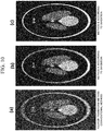
- FIG. 10 illustrates an example in which phase recovery was performed by using a numerical phantom that simulates a CT image inside a human body
- FIG. 10(a) is a phase image obtained by using the Fourier transform method as a conventional method
- FIG. 10(b) is a phase image obtained by using the method A according to the present invention
- FIG. 10(c) is a phase image obtained by using the method B according to the present invention.
- the phase image obtained by using the method A or the method B according to the present invention clearly has a higher spatial resolution than the phase image obtained by using the conventional Fourier transform method, and in addition, it can be understood that the phase image obtained by using the method B has more accurate boundaries and details than the phase image obtained by using the method A.
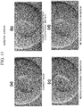
- FIG. 11 illustrates results of simulation which was performed by using a differential phase image of polymer spheres (diameter of 5/16 inches), and illustrates, as well as (a) a phase image (correct phase image) of a test object, (b) a phase image obtained by using the Fourier transform method, (c) a phase image obtained by using the method A according to the present invention, and (d) a phase image obtained by using the method B according to the present invention.
- the resolution is significantly lowered.
- the method A according to the present invention of FIG. 11(c) the resolution is higher as a whole, and further, even the boundaries are substantially correctly recovered with the method B according to the present invention of FIG. 11(d) .
- FIG. 12 illustrates results of phase recovery which was performed by using real data of polymers imaged by a Talbot interferometer.
- the imaging was performed in Spring-8 (large-scale synchrotron radiation facility).
- the size of the captured image is 2048 x 1024 pixels, and a period of the moire fringes is 22 pixels.
- FIG. 12(a) is a phase image obtained by using the Fourier transform method as a conventional method
- FIG. 12(b) is a phase image obtained by using the method A according to the present invention
- FIG. 12(c) is a phase image obtained by using the method B according to the present invention.
- phase image obtained by using the method A or the method B according to the present invention is less affected by noise and clearly has a higher spatial resolution than the phase image obtained by using the conventional Fourier transform method, and in addition, it can be understood that the phase image obtained by using the method B has more accurate boundaries and details than the phase image obtained by using the method A.
- the phase of the test object can be acquired with high accuracy with at least a single imaging operation.
- the weight is calculated by using the approximation phase image.
- the approximation phase image is not limited to the image according to the present method A or the Fourier transform method.
- the phase image obtained by using any other method can also be used for the weight calculation.
- the images include an image of the same object imaged by using another apparatus or hardware, previous measurement data (if any) or the like, an image of another known object with a similar structure, and the like.
- the approximation phase image is not available, it is possible to use the position information of a discontinuous place of the object. For example, an absorption captured image of the same object is used.
- phase imaging method and the phase imaging apparatus according to the present invention shall be preferably used in a high-speed phase CT imaging apparatus or the like using a Talbot interferometer as illustrated in FIG. 12 as well, particularly by exploiting convenience of its operation (motionlessness of diffraction gratings). Note that, here, fringe scan is not performed.
- phase X-ray CT that performs image generation of phase shift distribution based on line integral data of phase shift distribution in a case of X-ray irradiation
- a PET positron emission CT
- SPECT single photon radiation CT
- a nuclear medical imaging apparatus for generating an image of radioactive drug distribution administered into a body
- a CT using wave motions of ultrasonic waves, microwaves, acoustic waves, earthquake waves, or the like
- an electron beam CT, magnetic resonance imaging (MRI) using image reconfiguration from projected data and the like.
- object or “image” in the present invention refers to spatial distribution of a physical amount to be imaged.
- phase value can also be recovered by using the extracted numerical values of the phase shift of the quantum beam, the diffraction, or the image including the diffraction.
- the present invention provides a phase imaging method of obtaining an image of a test object by using a phase change that is obtained through radiation of quantum beams such as X-rays, and a phase imaging apparatus that uses the phase imaging method.
Landscapes
- Health & Medical Sciences (AREA)
- Analytical Chemistry (AREA)
- Physics & Mathematics (AREA)
- Life Sciences & Earth Sciences (AREA)
- Chemical & Material Sciences (AREA)
- Biochemistry (AREA)
- General Health & Medical Sciences (AREA)
- General Physics & Mathematics (AREA)
- Immunology (AREA)
- Pathology (AREA)
- Radiology & Medical Imaging (AREA)
- Nuclear Medicine, Radiotherapy & Molecular Imaging (AREA)
- Toxicology (AREA)
- Analysing Materials By The Use Of Radiation (AREA)
Abstract
Description
- The present invention relates to a phase imaging method of obtaining an image of a test object by using a phase change that is obtained through radiation of quantum beams such as X-rays, and further relates to a phase imaging apparatus using the phase imaging method.
- X-rays can penetrate substances, unlike visible light. Thus, with such X-rays, an internal structure of an object can be observed. Nowadays, X-rays are applied in a wide range of fields, such as X-ray imaging at hospitals and industrial non-destructive inspection. In usual X-ray imaging, the intensity of the X-rays changes due to absorption of an object when the X-ray penetrates the object, thereby forming a contrast image. In such an apparatus using an absorption rate, the heavier the element that constitutes an object, the greater the absorption of X-rays, and an image with a higher contrast can be obtained. However, to observe an object with low absorption, for example, a light element (having a small atomic quantity) such as a soft tissue of an organism, there is a problem in that a high contrast may not easily be obtained.
- In view of this, as illustrated in Citation List below, research on X-ray phase imaging methods has been conducted since the 1990s.
-
- PTL 1:
WO 2004058070 - PTL 2:
WO 2010050483 -
- NPL 1: A. Bravin, P. Coan, and P. Suortti, "X-ray phase-contrast imaging: from pre-clinical applications towards clinics," Phys. Med. Biol. 58, R1 (2013).
- NPL 2: F. Pfeiffer, C. Grunzweig, O. Bunk, G. Frei, E. Lehmann, and C. David, "Neutron Phase Imaging and Tomography," Phys. Rev. Lett. 96, 215505 - Published 2 June 2006; Erratum Phys. Rev. Lett. 97, 0 69905 (2006).
- NPL 3: A. Momose, S. Kawamoto, I. Koyama, Y. Hamaishi, K. Takai, and Y. Suzuki, "Demonstration of X-Ray Talbot interferometry," Jpn. J. Appl. Phys. 42, L866-L868 (2003).
- NPL 4: T. Weitkamp, A. Diaz, C. David, F. Pfeiffer, M. Stampanoni, P. Cloetens, and E. Ziegler, "X-ray phase imaging with a grating interferometer," Opt. Express 12 (16), 6296-6304 (2005).
- NPL 5: M. Takeda, H. Ina and S. Kobayashi, "Fourier-transform method of fringe-pattern analysis for computer-based topography and interferometry," J. Opt. Soc. Am. 72, 156-160 (1982).
- NPL 6: Y. Ge, K. Li, J. Garrett, and G. H. Chen, "Grating based X-ray differential phase contrast imaging without mechanical phase stepping," Opt. ).
- NPL 7: C. Kottler, F. Pfeiffer, O. Bunk, C. Gr·· unzweig, and C. David, "Grating interferometer based scanning setup for hard X-ray phase contrast imaging," Rev. Sci. Instrum. 78, 043710 (2007).
- NPL 8: C. Arboleda, Z. Wang Z, and M. Stampanoni, "Tilted-grating approach for scanning-mode X-ray phase contrast imaging," Opt. Express 22 (13), 15447-15458 (2014).
- In these methods, a phase change caused when X-rays penetrate an object is measured. In other words, by making use of the fact that a phase change when X-rays penetrate an object made of light elements is far greater than an absorbtion change, an image with a high contrast is generated [NPL 1]. Further, in recent years, these methods have also been applied to a radiation source of neutron beams or the like [NPL 2].
- Among a large number of developed imaging methods, in particular, a phase imaging method that uses Talbot interference by using diffraction gratings has been attracting attention because a regular X-ray tube can be used to produce a compact apparatus usable in hospitals or the like.
- On the other hand, in a phase imaging method, a fringe-scanning method is known as a method of recovering phase from a captured intensity distribution image [NPLs 3 and 4 and PTL 1]. In this method, diffraction gratings are moved at least three times in a grating period direction, thereby performing capturing of a plurality of images. Note that each movement distance is substantially at the sub-micron level. Thus, it is required for the apparatus to have significantly high accuracy/stability, and also to have strict management for temperature change and the like in a surrounding environment for use. In addition, three or more times of movement are required, and thus it is difficult to apply the method to dynamic measurement of a moving (or changing) object, for example, visual monitoring of cell cultivation or the like.
- In view of the above, a Fourier transform method has been proposed [NPL 5 and PTL 2]. In this method, the phase is calculated by performing processing using Fourier transform on a captured interference fringe image, and the phase can be acquired with a single imaging operation. However, in the Fourier transform method, a large number of high-frequency components are lost, and thus spatial resolution is reduced. This signifies that fine structures of a test object and the like are lost.
- In addition to the above, a method using a special diffraction grating [NPL 6], a method using a one-dimensional sensor [NPLs 7 and 8], and the like have been proposed. However, all of those methods require new hardware.
- Under such circumstances, the present invention is made in light of the conventional technologies described above, and more specifically has an object to provide a phase imaging method that allows to acquire phase of a test object having a high spatial resolution with at least a single imaging operation without a need of improvements in an existing apparatus and equipment (in particular, without improvement/change in hardware), and a phase imaging apparatus using the phase imaging method.
- In order to achieve the object described above, first, the present invention proposes a phase imaging method including causing a quantum beam from a radiation source to be incident on a detector through a test object and at least one phase grating, and obtaining a phase image of the test object, based on intensity distribution of a beam in a pixel constituting the detector, wherein the intensity distribution of the beam at least includes information of absorption (a0), visibility (V), and phase (ϕ), at least three adjacent pixels are assumed to have a substantially identical value for each of the absorption (a0), the visibility (V), and the phase (ϕ) through variable approximation of an image, and the absorption, the visibility, and the phase are obtained, based on at least one measurement image.
- Moreover, in order to achieve the object described above, the present invention proposes a phase imaging method including causing a quantum beam from a radiation source to be incident on a detector through a test object and at least one phase grating, and obtaining a phase image of the test object, based on intensity distribution of a beam in a pixel constituting the detector, wherein weighting processing is performed that gives a weight depending on similarity between each pixel and a phase value (or structure) of the pixel to be obtained by using an approximation phase image given in advance, and subsequently, absorption, visibility, and phase are obtained based on at least one measurement image by using the weight.
- In addition, the present invention proposes a phase imaging apparatus including a radiation source configured to generate a quantum beam, a holder configured to hold a test object to which a beam from the radiation source is radiated, a detector configured to receive the beam from the test object through at least one phase grating, and a processing unit configured to obtain a phase image of the test object, based on intensity distribution of the beam in a pixel constituting the detector, wherein the processing unit is the phase imaging method described above.
- According to the present invention described above, useful excellent effects can be achieved by providing a phase imaging method and a phase imaging apparatus that allow acquisition of the phase of the test object having a high spatial resolution with at least a single imaging operation without requiring improvements in an existing apparatus and equipment (in particular, without improvement/change in hardware).
-
-
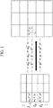
FIG. 1 is a diagram illustrating a principle of a method A according to an embodiment (Example 1) of the present invention. -
FIG. 2 is a diagram illustrating the principle of the method A. -
FIG. 3 is a diagram illustrating a modification of the method A. -
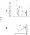
FIG. 4 is a diagram illustrating a convex function minimization problem related to three variables of the method A. -
FIG. 5 is a diagram illustrating a configuration of a Talbot interferometer as an apparatus and equipment to which the method A can be applied. -
FIG. 6 is a diagram illustrating a configuration of a Talbot-Lau interferometer as an apparatus and equipment to which the method A can be applied. -
FIG. 7 is a diagram illustrating a configuration of a Lau interferometer as an apparatus and equipment to which the method A can be applied. -
FIG. 8 is a diagram illustrating weights of a method B according to another embodiment (Example 2) of the present invention. -
FIG. 9 is a diagram illustrating calculation of the weights of the method B. -
FIG. 10 is a diagram illustrating an example in which recovery of phase is performed by using a numerical phantom by using the methods A and B according to the present invention, in comparison to a conventional technology. -
FIG. 11 is a diagram illustrating a phase image of polymer spheres obtained by using the methods A and B according to the present invention, in comparison to a conventional technology. -
FIG. 12 is a diagram illustrating a phase image obtained by using the methods A and B according to the present invention by using real data obtained by imaging polymers with the Talbot interferometer, in comparison with a conventional technology. -
FIG. 13 is a diagram illustrating an example of a configuration of a high-speed phase CT imaging apparatus using the Talbot interferometer to which a phase imaging method and a phase imaging apparatus according to the present invention can be applied. - In the following, embodiments of the present invention will be described. Prior to the description, here, a principle of the present invention will be described in detail with reference to the attached drawings.
- In an apparatus that forms interference fringes by using a radiation source that generates so-called quantum beams, including X-rays, neutron beams, visible light, and the like, what is directly measured by a detector (two-dimensional) is not phase but is intensity distribution of moire interference fringes (or a self image due to the Talbot effect) deformed due to a test object. In general, the intensity distribution measured by the detector can be expressed as follows:
[Math. 1]
- Note that a0 represents absorption, V represents visibility, ϕ represents differential phase (also referred to as difference phase, or simply as "phase"), and f represents a waveform representing a sine wave of the moire interference fringes. In phase imaging, phase is obtained, and thus imaging of a background when there is no test object and imaging when there is a test object are performed. Here, f is obtained from the imaging of background. When imaging of a background cannot be performed, f can also be estimated by using a local portion of a single captured image where there is a small phase change of an object (that is, where there is small deformation of moire interference fringes).
- As described above, in Expression (1), there are three variables in each pixel of the detector, and to obtain the phase, at least three different pieces of data are required. As described above, in a conventional fringe-scanning method, a plurality of captured images are obtained through imaging by moving diffraction gratings M (M ≥ 3) times. Then, through the use of the obtained imaged data of the plurality of images, for example, the phase is obtained with the least squares method or the like. With this method, the phase can be obtained with a high spatial resolution. However, as described above, high accuracy is required in movement of the diffraction gratings. Each movement distance of the diffraction gratings in the fringe-scanning method is uniform, and is 1/M of the period of the diffraction gratings. In general, the period of the diffraction gratings is several micrometers, and thus the movement is performed substantially at a sub-micron level. Accordingly, strict stability and the like are required for the apparatus/equipment.
- The present invention provides a method that enables three variables, namely absorption (a0), visibility (V), and phase (ϕ), to be obtained with at least a single imaging operation. As has been described in the above, to obtain the phase, at least three different pieces of data are required. In the present invention, this problem is solved by variable approximation of an image.
- Specifically, as illustrated in
FIG. 1 as well, in three adjacent pixels of the detector (two-dimensional), Expression (1) shown above assumes that absorption (a0), visibility (V), and phase (ϕ) are substantially the same as follows.
[Math. 2]
[Math. 3]
- Note that description will be herein given using only three pixels, which similarly applies to the following description. However, as a matter of course, calculation can also be performed by using a larger number of pixels.
- Under this assumption, based on Expression (1) shown above, the expression can be expressed as follows: This means that a piece of data I-1 (m, n) is added for a pixel (m, n).
[Math. 4]
- In addition, according to the same approximation, as shown below, at least three pieces of data can be obtained.
[Math. 5]
- As described above, according to the variable approximation of the image, three pieces of data are present for three variables, and thus the phase (ϕ) can be obtained.
- According to the variable approximation of an image, that is, approximation by Expressions (2) and (3) shown above, as illustrated in
FIG. 2 as well, the piece of data corresponding to one pixel is increased from one to three pieces. - Note that, here, the variable approximation of an image described above is not limited to a vertical direction. As shown in
FIGS. 3(a) to (c) , various directions such as a horizontal direction and an oblique direction are possible as well. Here, it is assumed that absorption (a0), visibility (V), and phase (ϕ) are substantially the same in the three adjacent pixels as a specific example for the sake of description. As a matter of course, as shown inFIGS. 3(d) and (e) , the absorption, the visibility, and the phase can be obtained by using the method according to the present invention, assuming that the absorption (a0), the visibility (V), and the phase (ϕ) are substantially the same in a larger number of surrounding pixels. As a matter of course, the variable approximation can also be performed using different numbers of pixels, such as by assuming that the absorption and the visibility are substantially the same in five adjacent pixels and assuming that the phase is substantially the same in three adjacent pixels, for example. - In this manner, by solving a minimization problem by using data obtained through the variable approximation of the image, the phase can be obtained. Specifically, as shown below, the phase can be obtained by solving a problem of minimization of a difference between the data obtained according to Expression (5) shown above and a theoretical value according to Expression (1) shown above (Lp (p ≥ 0) norm minimization of a difference between a measured value and the theoretical value).
[Math. 6]
- Note that Ik (k = 0, ±1) represents a plurality of pieces of data obtained through the variable approximation of the same image as that of Expression (5). Here, if p = 2, a least squares problem is to be solved.
- Expression (6) for this problem can be solved by using various existing iterative methods (for example, the steepest descent method or the like), with an initial value of Expression (7) shown below being given.
[Math. 7]
- Then, an obtained optimal solution {a0, V, ϕ} corresponds to the absorption (a0), the visibility (V), and the phase (ϕ) to be obtained.
- However, Expression (6) includes a trigonometric function of the variable ϕ, and is a minimization problem of a non-convex function. Thus, depending on the initial value, the convergence may result in a wrong solution (for example, a local minimum value). In light of this, in the present invention, when p ≥ 1, a new analysis method as follows is proposed.
- First, for (a0, V, ϕ), variable conversion is performed as follows.
[Math. 8]
- Through such conversion, Expression (6) for the problem can be expressed as follows.
[Math. 9]
- Expression (9) is a minimization problem of a convex function related to the three variables (a0, bc, bs). Accordingly, as illustrated in
FIG. 4 , the convergence to a correct optimal solution is ensured without depending on the initial value to start with. After obtaining the optimal solutions a0, bc, and bs, the absorption (a0), the phase (ϕ), and the visibility (V) are obtained through the following variable conversion.
[Math. 10]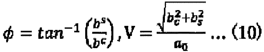
- Thus, according to the phase imaging method of the present invention described above in detail (method A), the phase of the test object having a high spatial resolution can be acquired with at least a single imaging operation without a need of significant improvement in hardware through the use of an existing apparatus and equipment. In other words, in comparison to the conventional fringe-scanning method, the following can be achieved:
- A. The requirement of high stability in the fringe-scanning method is eliminated owing to the motionlessness of the diffraction gratings.
- B. The operation of the apparatus is simplified owing to the single imaging operation.
- In addition, in comparison to the conventional Fourier transform method, the following can be achieved:
- C. By maintaining a higher spatial resolution, an image can be provided that allows a larger number of fine internal structures to be seen (see
FIG. 10(b) andFIG. 11(c) to be described later). - D. Further, in the analysis method, a solution is obtained through conversion to a minimization problem of a convex function, and thus regardless of a given specific initial value, an optimal solution is provided. This shall be significantly important in actual application, in particular.
- The phase imaging method described above (method A) can also be applied to an existing apparatus and equipment, and can be applied to, for example, as schematically illustrated in
FIGS. 5 to 7 as well, a Talbot interferometer (FIG. 5 ), a Talbot-Lau interferometer (FIG. 6 ), a Lau interferometer (FIG. 7 ), or the like that forms interference fringes by using an X-ray source (or a neutron radiation source). - As illustrated in
FIG. 5 , an X-ray Talbot interferometer uses anX-ray source 10 that generates X-rays, and includes aphase diffraction grating 21 that causes interference of the X-rays to be generated, anabsorption diffraction grating 22 that converts interference intensity distribution caused in a test object S into moire intensity distribution, and anX-ray detector 30. Note that, in the apparatus, a periodic image (self image) similar to the phase grating is generated due to the interference at a position that is apart from the grating by a certain distance. This phenomenon is referred to as the Talbot effect. Further, the second diffraction grating is disposed at the position where the self image is generated, to thereby form moire interference fringes. Thus, what is directly measured in the Talbot interferometer is not phase but is intensity distribution of the moire interference fringes deformed due to the test object, and intensity distribution I (m, n) measured with an image detector is, for example, transmitted to an image data-processing unit including a CPU as an arithmetic element, a RAM and a ROM as storage means, and the like, and the results are output as the absorption (a0), the visibility (V), and the phase (ϕ) through predetermined arithmetic processing. Note that the two-dimensional image detector 30 that detects the interference fringes in these interferometers is configured in such a manner that a large number of pixels as semiconductor X-ray detection elements are disposed flat, and for example, an electromagnetic wave detector and an image detector disclosed inJP 2002-26300 A - Further, the Talbot-Lau interferometer illustrated in
FIG. 6 further includes adiffraction grating 23 in front of theX-ray source 10. Further, the Lau interferometer illustrated inFIG. 7 includes a phase grating 24 between the X-ray source and the test object. With these interferometers as well, in a manner similar to the above, the intensity distribution I (m, n) measured in theimage detector 30 is, for example, transmitted to the image data-processing unit 100 including a CPU as an arithmetic element, a RAM and a ROM as storage means, and the like, and the results are output as the absorption (a0), the visibility (V), and the phase (ϕ) through predetermined arithmetic processing. - In this manner, the phase imaging method according to the present invention can also be easily applied to an existing apparatus and equipment, and through a predetermined arithmetic operation using imaged data (intensity signal (I)) obtained using the apparatus and equipment by the image data-processing unit, the phase of the test object having a high spatial resolution can be acquired from at least a single imaging operation.
- Subsequently, the present invention provides a method with which a solution having higher accuracy than that of the method A described above can be obtained with at least a single imaging operation when imperfect phase information is known in advance. Here, the known phase information described above can be acquired based on a phase image that is obtained by using the Fourier transform method as a conventional method, the method A according to the present invention described above, and the like.
- In the following description of the method B according to the present invention, the known phase information is referred to as an "approximation phase image".
- With this method as well, in a manner similar to the method A according to the invention, phase is obtained by solving a minimization problem. Here, the method B differs from the method A according to the invention described above in that a minimization problem of a weighted energy function is solved by using a weight function W (m, n). Here, the method will be described with one arbitrarily selected pixel (m, n) being fixed. Calculation can be performed in a similar manner at other positions as well. As for the weight, an approximation phase image is used, and points having close phase values (or structures) are searched for in a wide range in the pixel (m, n), and the more similar the points are, the greater weight is given. Further, the following weighted minimization problem is solved.
[Math. 11]
- Note that I1,k (l, k = 0, ±1, ...) represents a plurality of pieces of data obtained according to an approximation (as in Expression (5) shown above), and be and bs are variables defined in Expression (8). The weight W1,k is defined as follows.
[Math. 12]
- Here, W (m + 1, n + k) (1, k = 0, ±1, ...) represents similarity between phase values of a target pixel (m, n) whose phase is to be obtained and a pixel (m + 1, n + k) (1, k = 0, ±1, ...), and a calculation method thereof will be described later.
- Here, the effect of the weight will be described. For example, it is assumed that the pixel (m, n) is a boundary between an object and another object as shown in
FIG. 8 , and the phase value of the pixel (m, n) is significantly different from that of an adjacent pixel (m, n - 1). In this case, the assumption of Expression (3) shown above is incorrect. Thus, an error of a phase image obtained by using the data of the pixel (m, n - 1) is also increased. - In the method B according to the present invention, this problem is alleviated by using the weight W1,k. Specifically, first, as illustrated in
FIG. 9 , the weight is calculated by using the approximation phase image. The phase value of the pixel (m, n) is significantly different from that of the pixel (m, n - 1), and the pixel (m, n) and the pixel (m, n - 1) are not similar to each other, thus causing the weight to be smaller. Thus, in Expression (12) shown above, the weight W0,-1 is as follows.
[Math. 13]
- In this case, by using the weight in Expression (11) shown above, the data of the pixel (m, n - 1) is eliminated from the calculation. This signifies that the approximation of Expression (3) shown above is converted to a more correct approximation. As a result, more accurate phase can be obtained even if there is a discontinuous boundary.
- Subsequently, the calculation method of the weight function W (m, n) described above will be described. As for the calculation method of the weight, various weights can be used. As one example thereof, in the following, a specific weight calculation method using non-local means will be described.
- For example, it is assumed that there is an approximation phase image as shown in
FIG. 9 . A situation of obtaining a phase value in a target pixel (A5) is considered. In this case, the weight of each of the surrounding pixels is determined by the phase value (or the structure) of the approximation phase image. For example, as illustrated inFIG. 9 as well, the weight of each pixel (B5) is determined by using a target block around the target pixel (A5) and a reference block around (B5) as follows.
[Math. 14]
- Note that C represents a normalization constant for causing the sum of the weights of all of the operating pixels to be one.
- Here, h1 > 0 is a parameter that is defined in advance. Expression (14) is a weight according to similarity between blocks, and the more similar the phase values (or the structures) are, the greater weight is given.
- Next, to verify the effect of the phase imaging method and the phase imaging apparatus according to the present invention described above, processing with the methods A and B was performed according to the present invention by using a numerical phantom and an X-ray differential phase image. How to create a contrast image will be described below. In the experiment, first, a single piece of interference fringe data is generated according to Expression (1) by using phase (ϕ), absorption (a0), and visibility (V) of a hypothetical object. Phase images obtained from a resultant interference fringe image by using the Fourier transform method and the present invention (the method A or the method B) are shown.
-
FIG. 10 illustrates an example in which phase recovery was performed by using a numerical phantom that simulates a CT image inside a human body;FIG. 10(a) is a phase image obtained by using the Fourier transform method as a conventional method,FIG. 10(b) is a phase image obtained by using the method A according to the present invention, andFIG. 10(c) is a phase image obtained by using the method B according to the present invention. As is apparent from these phase images, the phase image obtained by using the method A or the method B according to the present invention clearly has a higher spatial resolution than the phase image obtained by using the conventional Fourier transform method, and in addition, it can be understood that the phase image obtained by using the method B has more accurate boundaries and details than the phase image obtained by using the method A. -
FIG. 11 illustrates results of simulation which was performed by using a differential phase image of polymer spheres (diameter of 5/16 inches), and illustrates, as well as (a) a phase image (correct phase image) of a test object, (b) a phase image obtained by using the Fourier transform method, (c) a phase image obtained by using the method A according to the present invention, and (d) a phase image obtained by using the method B according to the present invention. As is apparent from the results as well, with the conventional method (Fourier transform method) ofFIG. 11(b) , the resolution is significantly lowered. On the other hand, with the method A according to the present invention ofFIG. 11(c) , the resolution is higher as a whole, and further, even the boundaries are substantially correctly recovered with the method B according to the present invention ofFIG. 11(d) . -
FIG. 12 illustrates results of phase recovery which was performed by using real data of polymers imaged by a Talbot interferometer. The imaging was performed in Spring-8 (large-scale synchrotron radiation facility). The size of the captured image is 2048 x 1024 pixels, and a period of the moire fringes is 22 pixels.FIG. 12(a) is a phase image obtained by using the Fourier transform method as a conventional method,FIG. 12(b) is a phase image obtained by using the method A according to the present invention, andFIG. 12(c) is a phase image obtained by using the method B according to the present invention. As is apparent from these phase images, the phase image obtained by using the method A or the method B according to the present invention is less affected by noise and clearly has a higher spatial resolution than the phase image obtained by using the conventional Fourier transform method, and in addition, it can be understood that the phase image obtained by using the method B has more accurate boundaries and details than the phase image obtained by using the method A. - As has been described in detail in the above, with the phase imaging method according to the present invention, the phase of the test object can be acquired with high accuracy with at least a single imaging operation.
- In comparison to the conventional fringe-scanning method,
- A. The requirement of high stability in the fringe-scanning method is eliminated because the movement of the diffraction gratings is not required.
- B: The operation of the apparatus and the equipment is further simplified because the phase image can be obtained with a single imaging operation.
- C: Dynamic measurement for a moving object or a changing object can be more correctly performed because the phase image can be obtained with a single imaging operation.
- In addition, in comparison to the conventional Fourier transform method,
- D: By maintaining a higher spatial resolution, an image can be provided that allows a larger number of fine internal structures to be seen.
- E: Although the accuracy of the method according to the present invention depends on the period of imaged interference fringes, a phase image can be obtained such that the accuracy is not significantly lowered even when the period is greater than the period usually used in the Fourier transform method (by approximately five or six pixels per period) (for example, several tens of pixels per period). In the X-ray phase imaging using the diffraction gratings, when the period of the moire fringes is increased, the visibility is significantly improved. Thus, in the present method, an image with more satisfactory image quality than that of the conventional method can be obtained.
- With the method B according to the present invention, specific weight calculation is performed by using the non-local means. As a matter of course, however, various methods can be applied. Examples of the methods include a filter such as a bilateral filter and a method other than the filter in which a greater weight is obtained as the images are more similar to each other.
- With the method B according to the present invention described above, the weight is calculated by using the approximation phase image. The approximation phase image is not limited to the image according to the present method A or the Fourier transform method. As a matter of course, the phase image obtained by using any other method can also be used for the weight calculation. Examples of the images include an image of the same object imaged by using another apparatus or hardware, previous measurement data (if any) or the like, an image of another known object with a similar structure, and the like. In addition, even if the approximation phase image is not available, it is possible to use the position information of a discontinuous place of the object. For example, an absorption captured image of the same object is used.
- As described above, the phase imaging method and the phase imaging apparatus according to the present invention shall be preferably used in a high-speed phase CT imaging apparatus or the like using a Talbot interferometer as illustrated in
FIG. 12 as well, particularly by exploiting convenience of its operation (motionlessness of diffraction gratings). Note that, here, fringe scan is not performed. - Note that the technology to which the present invention can be applied is not limited to those described above, and application is also possible to, for example, a phase X-ray CT that performs image generation of phase shift distribution based on line integral data of phase shift distribution in a case of X-ray irradiation, a PET (positron emission CT) or a SPECT (single photon radiation CT) as a nuclear medical imaging apparatus for generating an image of radioactive drug distribution administered into a body, a CT using wave motions of ultrasonic waves, microwaves, acoustic waves, earthquake waves, or the like, an electron beam CT, magnetic resonance imaging (MRI) using image reconfiguration from projected data, and the like. In other words, the term "object" or "image" in the present invention refers to spatial distribution of a physical amount to be imaged.
- Further, numerical values of a phase shift, a phase shift of a quantum beam, diffraction, or an image including diffraction are extracted from a plurality of sets acquired through addition of an optical element or a position change thereof, and the phase value can also be recovered by using the extracted numerical values of the phase shift of the quantum beam, the diffraction, or the image including the diffraction.
- The present invention provides a phase imaging method of obtaining an image of a test object by using a phase change that is obtained through radiation of quantum beams such as X-rays, and a phase imaging apparatus that uses the phase imaging method.
-
- 10
- Radiation source
- 21 - 24
- Diffraction (phase) grating
- S
- Test object
- 100
- Image data-processing unit
Claims (15)
- A phase imaging method, comprising:causing a quantum beam from a radiation source to be incident on a detector through a test object and at least one phase grating, and obtaining a phase image of the test object, based on intensity distribution of a beam in a pixel constituting the detector, whereinthe intensity distribution of the beam at least includes information of absorption (a0), visibility (V), and phase (ϕ),at least three adjacent pixels are assumed to have a substantially identical value for each of the absorption (a0), the visibility (V), and the phase (ϕ) through variable approximation of an image, andthe absorption, the visibility, and the phase are obtained, based on at least one measurement image.
- The phase imaging method according to Claim 1, wherein
the intensity distribution of the beam in the pixel (m, n) of the detector is expressed as follows, where a0 represents absorption, V represents visibility, ϕ represents phase, and f represents an interference fringe on a background, andthe absorption, the visibility, and the phase are obtained based on at least one measurement image by setting as follows,
- The phase imaging method according to Claim 1, wherein
the absorption, the visibility, and the phase are obtained by using Lp (p ≥ 0) norm minimization of a difference between a measured value and a theoretical value. - The phase imaging method according to Claim 3, wherein
in the Lp norm minimization, for p ≥ 1, a non-convex minimization problem is converted into a convex function minimization problem through variable conversion to obtain the absorption, the visibility, and the phase. - A phase imaging method, comprising:causing a quantum beam from a radiation source to be incident on a detector through a test object and at least one phase grating, and obtaining a phase image of the test object, based on intensity distribution of a beam in a pixel constituting the detector, whereinweighting processing is performed that gives a weight depending on similarity between each pixel and a phase value (or structure) of the pixel to be obtained by using an approximation phase image given in advance, and subsequently,absorption, visibility, and phase are obtained based on at least one measurement image by using the weight.
- The phase imaging method according to Claim 5, wherein
the absorption, the visibility, and the phase are obtained based on the at least one measurement image by setting as follows,
- The phase imaging method according to Claim 6, wherein
the absorption, the visibility, and the phase are obtained by using weighted Lp (p ≥ 0) norm minimization of a difference between a measured value and a theoretical calculation value. - The phase imaging method according to Claim 7, wherein
in the weighted Lp norm minimization, for p ≥ 1, a non-convex minimization problem is converted into a convex function minimization problem through variable conversion to obtain the absorption, the visibility, and the phase. - The phase imaging method according to Claim 5, wherein
the approximation phase image given in advance is a phase image obtained by using any of the methods according to Claims 1 to 5. - The phase imaging method according to Claim 5, wherein
the approximation phase image given in advance is a phase image obtained by using a Fourier transform method. - The phase imaging method according to Claim 5, wherein
the approximation phase image given in advance is an image of an identical object captured in another apparatus, previous measurement data, or an image of another known object with a similar structure. - The phase imaging method according to Claim 5, wherein
the weighting is performed by using calculation using non-local means, by using a filter such as a bilateral filter, or by using a method in which a greater weight is obtained as images are more similar to each other. - The phase imaging method according to Claim 5, wherein
instead of the approximation phase image, an absorption captured image of a discontinuous place of the test object is used. - A phase imaging apparatus, comprising:a radiation source configured to generate a quantum beam;a holder configured to hold a test object to which a beam from the radiation source is radiated;a detector configured to receive the beam from the test object through at least one phase grating; anda processing unit configured to obtain a phase image of the test object, based on intensity distribution of the beam in a pixel constituting the detector, whereinthe processing unit obtains absorption, visibility, and phase by executing the phase imaging method according to any one of Claims 1 to 4.
- A phase imaging apparatus, comprising:a radiation source configured to generate a quantum beam;a holder configured to hold a test object to which a beam from the radiation source is radiated;a detector configured to receive the beam from the test object through at least one phase grating; anda processing unit configured to obtain a phase image of the test object, based on intensity distribution of the beam in a pixel constituting the detector, whereinthe processing unit obtains absorption, visibility, and phase by executing the phase imaging method according to any one of Claims 5 to 13.
Applications Claiming Priority (2)
| Application Number | Priority Date | Filing Date | Title |
|---|---|---|---|
| JP2018111563 | 2018-06-12 | ||
| PCT/JP2019/023266 WO2019240165A1 (en) | 2018-06-12 | 2019-06-12 | Phase image capturing method and phase image capturing device using same |
Publications (3)
| Publication Number | Publication Date |
|---|---|
| EP3809121A1 true EP3809121A1 (en) | 2021-04-21 |
| EP3809121A4 EP3809121A4 (en) | 2022-03-09 |
| EP3809121B1 EP3809121B1 (en) | 2026-03-18 |
Family
ID=68842923
Family Applications (1)
| Application Number | Title | Priority Date | Filing Date |
|---|---|---|---|
| EP19819980.4A Active EP3809121B1 (en) | 2018-06-12 | 2019-06-12 | Phase image capturing method and phase image capturing device using same |
Country Status (4)
| Country | Link |
|---|---|
| US (1) | US11181487B2 (en) |
| EP (1) | EP3809121B1 (en) |
| JP (2) | JP7347827B2 (en) |
| WO (1) | WO2019240165A1 (en) |
Family Cites Families (11)
| Publication number | Priority date | Publication date | Assignee | Title |
|---|---|---|---|---|
| JP3589954B2 (en) | 2000-07-04 | 2004-11-17 | シャープ株式会社 | Electromagnetic wave detector, image detector, and method of manufacturing electromagnetic wave detector |
| EP1623671A4 (en) | 2002-12-26 | 2008-11-05 | Atsushi Momose | X-ray imaging system and imaging method |
| EP2343537B1 (en) | 2008-10-29 | 2019-04-10 | Canon Kabushiki Kaisha | X-ray imaging device and x-ray imaging method |
| JP5601909B2 (en) * | 2010-07-06 | 2014-10-08 | 国立大学法人 東京大学 | X-ray imaging apparatus and X-ray imaging method using the same |
| JP2012143491A (en) | 2011-01-14 | 2012-08-02 | Fujifilm Corp | Radiographic apparatus and radiation image detector |
| JP2014155508A (en) * | 2011-06-08 | 2014-08-28 | Fujifilm Corp | Radiography system |
| JP6116222B2 (en) | 2012-12-13 | 2017-04-19 | キヤノン株式会社 | Arithmetic device, program, and imaging system |
| US8989347B2 (en) * | 2012-12-19 | 2015-03-24 | General Electric Company | Image reconstruction method for differential phase contrast X-ray imaging |
| JP2016000139A (en) | 2014-06-12 | 2016-01-07 | キヤノン株式会社 | Phase information acquisition apparatus and imaging system |
| JP6418066B2 (en) | 2015-05-21 | 2018-11-07 | コニカミノルタ株式会社 | Phase image processing method, phase image processing apparatus, image processing apparatus, and image processing program |
| CN107850680B (en) | 2015-07-21 | 2021-09-21 | 皇家飞利浦有限公司 | X-ray detector for phase contrast and/or dark field imaging |
-
2019
- 2019-06-12 WO PCT/JP2019/023266 patent/WO2019240165A1/en not_active Ceased
- 2019-06-12 JP JP2020525615A patent/JP7347827B2/en active Active
- 2019-06-12 US US17/250,099 patent/US11181487B2/en active Active
- 2019-06-12 EP EP19819980.4A patent/EP3809121B1/en active Active
-
2023
- 2023-08-31 JP JP2023141826A patent/JP7610873B2/en active Active
Also Published As
| Publication number | Publication date |
|---|---|
| EP3809121B1 (en) | 2026-03-18 |
| JP7347827B2 (en) | 2023-09-20 |
| US11181487B2 (en) | 2021-11-23 |
| JP2023155462A (en) | 2023-10-20 |
| US20210215624A1 (en) | 2021-07-15 |
| EP3809121A4 (en) | 2022-03-09 |
| JPWO2019240165A1 (en) | 2021-06-24 |
| WO2019240165A1 (en) | 2019-12-19 |
| JP7610873B2 (en) | 2025-01-09 |
Similar Documents
| Publication | Publication Date | Title |
|---|---|---|
| EP3346260B1 (en) | Radiographic image generating device | |
| Miranda et al. | Static and dynamic error of a biplanar videoradiography system using marker-based and markerless tracking techniques | |
| US8972191B2 (en) | Low dose single step grating based X-ray phase contrast imaging | |
| EP2442722B1 (en) | Correction method for differential phase contrast imaging | |
| US9084528B2 (en) | Phase contrast imaging | |
| Miao et al. | Motionless phase stepping in X-ray phase contrast imaging with a compact source | |
| Grangeat | Tomography | |
| JP2016049455A (en) | X-ray computed tomography apparatus and image reconstruction apparatus | |
| Tang et al. | Characterization of imaging performance in differential phase contrast ct compared with the conventional ct: Spectrum of noise equivalent quanta neq (k) | |
| Brombal et al. | Monochromatic breast computed tomography with synchrotron radiation: phase-contrast and phase-retrieved image comparison and full-volume reconstruction | |
| Fu et al. | Helical differential X-ray phase-contrast computed tomography | |
| Maidment et al. | Comparing the imaging performance of computed super resolution and magnification tomosynthesis | |
| EP3809121B1 (en) | Phase image capturing method and phase image capturing device using same | |
| Seifert et al. | Single-shot talbot–lau x-ray dark-field imaging of a porcine lung applying the moiré imaging approach | |
| Thüring | Compact X-ray grating interferometry for phase and dark-field computed tomography in the diagnostic energy range | |
| Zhao et al. | Optimization of cone-beam CT scan orbits for cervical spine imaging | |
| US20220273254A1 (en) | X-ray imaging device and associated imaging method | |
| Seifert et al. | Measurement and simulative proof concerning the visibility loss in x-ray Talbot-Lau Moiré imaging | |
| Pyakurel | Phase and dark field radiography and CT with mesh-based structured illumination and polycapillary optics | |
| Sato et al. | Single-shot x-ray phase-contrast imaging using two-dimensional gratings | |
| Naranjo Barros | Neural network optimization of Speckle-based phase-contrast X-ray imaging for mammography applications | |
| Lopez-Montes et al. | Feasibility of dynamic lung tomosynthesis using stationary x-ray source arrays | |
| Zdora | Principles and State of the Art of X-ray Speckle-Based Imaging | |
| Gharibshahi et al. | Investigation of Novel Muon Imaging System in Cardiovascular Operations: A Simulation Approach | |
| Rubin et al. | Reconstruction method for x-ray imaging capsule |
Legal Events
| Date | Code | Title | Description |
|---|---|---|---|
| STAA | Information on the status of an ep patent application or granted ep patent |
Free format text: STATUS: THE INTERNATIONAL PUBLICATION HAS BEEN MADE |
|
| PUAI | Public reference made under article 153(3) epc to a published international application that has entered the european phase |
Free format text: ORIGINAL CODE: 0009012 |
|
| STAA | Information on the status of an ep patent application or granted ep patent |
Free format text: STATUS: REQUEST FOR EXAMINATION WAS MADE |
|
| 17P | Request for examination filed |
Effective date: 20201124 |
|
| AK | Designated contracting states |
Kind code of ref document: A1 Designated state(s): AL AT BE BG CH CY CZ DE DK EE ES FI FR GB GR HR HU IE IS IT LI LT LU LV MC MK MT NL NO PL PT RO RS SE SI SK SM TR |
|
| AX | Request for extension of the european patent |
Extension state: BA ME |
|
| DAV | Request for validation of the european patent (deleted) | ||
| DAX | Request for extension of the european patent (deleted) | ||
| A4 | Supplementary search report drawn up and despatched |
Effective date: 20220204 |
|
| RIC1 | Information provided on ipc code assigned before grant |
Ipc: A61B 6/00 20060101ALI20220131BHEP Ipc: G01N 23/041 20180101AFI20220131BHEP |
|
| STAA | Information on the status of an ep patent application or granted ep patent |
Free format text: STATUS: EXAMINATION IS IN PROGRESS |
|
| 17Q | First examination report despatched |
Effective date: 20240405 |
|
| GRAP | Despatch of communication of intention to grant a patent |
Free format text: ORIGINAL CODE: EPIDOSNIGR1 |
|
| STAA | Information on the status of an ep patent application or granted ep patent |
Free format text: STATUS: GRANT OF PATENT IS INTENDED |
|
| INTG | Intention to grant announced |
Effective date: 20251022 |
|
| GRAS | Grant fee paid |
Free format text: ORIGINAL CODE: EPIDOSNIGR3 |
|
| GRAA | (expected) grant |
Free format text: ORIGINAL CODE: 0009210 |
|
| STAA | Information on the status of an ep patent application or granted ep patent |
Free format text: STATUS: THE PATENT HAS BEEN GRANTED |
|
| AK | Designated contracting states |
Kind code of ref document: B1 Designated state(s): AL AT BE BG CH CY CZ DE DK EE ES FI FR GB GR HR HU IE IS IT LI LT LU LV MC MK MT NL NO PL PT RO RS SE SI SK SM TR |
|
| REG | Reference to a national code |
Ref country code: CH Ref legal event code: F10 Free format text: ST27 STATUS EVENT CODE: U-0-0-F10-F00 (AS PROVIDED BY THE NATIONAL OFFICE) Effective date: 20260318 Ref country code: GB Ref legal event code: FG4D |
|
| REG | Reference to a national code |
Ref country code: IE Ref legal event code: FG4D |
|
| REG | Reference to a national code |
Ref country code: DE Ref legal event code: R096 Ref document number: 602019082634 Country of ref document: DE |