EP3809109A1 - Analyse intelligente des données d'un moteur à l'aide d'un algorithme en temps réel - Google Patents
Analyse intelligente des données d'un moteur à l'aide d'un algorithme en temps réel Download PDFInfo
- Publication number
- EP3809109A1 EP3809109A1 EP19203532.7A EP19203532A EP3809109A1 EP 3809109 A1 EP3809109 A1 EP 3809109A1 EP 19203532 A EP19203532 A EP 19203532A EP 3809109 A1 EP3809109 A1 EP 3809109A1
- Authority
- EP
- European Patent Office
- Prior art keywords
- samples
- data
- rotating machine
- real
- processing system
- Prior art date
- Legal status (The legal status is an assumption and is not a legal conclusion. Google has not performed a legal analysis and makes no representation as to the accuracy of the status listed.)
- Withdrawn
Links
Images


Classifications
-
- G—PHYSICS
- G01—MEASURING; TESTING
- G01H—MEASUREMENT OF MECHANICAL VIBRATIONS OR ULTRASONIC, SONIC OR INFRASONIC WAVES
- G01H1/00—Measuring characteristics of vibrations in solids by using direct conduction to the detector
- G01H1/003—Measuring characteristics of vibrations in solids by using direct conduction to the detector of rotating machines
-
- G—PHYSICS
- G01—MEASURING; TESTING
- G01M—TESTING STATIC OR DYNAMIC BALANCE OF MACHINES OR STRUCTURES; TESTING OF STRUCTURES OR APPARATUS, NOT OTHERWISE PROVIDED FOR
- G01M13/00—Testing of machine parts
- G01M13/04—Bearings
- G01M13/045—Acoustic or vibration analysis
-
- G—PHYSICS
- G01—MEASURING; TESTING
- G01N—INVESTIGATING OR ANALYSING MATERIALS BY DETERMINING THEIR CHEMICAL OR PHYSICAL PROPERTIES
- G01N29/00—Investigating or analysing materials by the use of ultrasonic, sonic or infrasonic waves; Visualisation of the interior of objects by transmitting ultrasonic or sonic waves through the object
- G01N29/44—Processing the detected response signal, e.g. electronic circuits specially adapted therefor
- G01N29/46—Processing the detected response signal, e.g. electronic circuits specially adapted therefor by spectral analysis, e.g. Fourier analysis or wavelet analysis
-
- G—PHYSICS
- G01—MEASURING; TESTING
- G01R—MEASURING ELECTRIC VARIABLES; MEASURING MAGNETIC VARIABLES
- G01R23/00—Arrangements for measuring frequencies; Arrangements for analysing frequency spectra
- G01R23/16—Spectrum analysis; Fourier analysis
- G01R23/165—Spectrum analysis; Fourier analysis using filters
- G01R23/167—Spectrum analysis; Fourier analysis using filters with digital filters
-
- G—PHYSICS
- G06—COMPUTING; CALCULATING OR COUNTING
- G06F—ELECTRIC DIGITAL DATA PROCESSING
- G06F17/00—Digital computing or data processing equipment or methods, specially adapted for specific functions
- G06F17/10—Complex mathematical operations
- G06F17/14—Fourier, Walsh or analogous domain transformations, e.g. Laplace, Hilbert, Karhunen-Loeve, transforms
- G06F17/141—Discrete Fourier transforms
Definitions
- the present invention relates to a computer-implemented method of Condition Monitoring (CM) for rotating machines like motors, a corresponding computer program, computer-readable medium and data processing system for CM for rotating machines as well as a system comprising the data processing system for CM for rotating machines.
- CM Condition Monitoring
- CM Condition Monitoring
- CM Middle-effect CM
- spectral information or rather spectral features of either the vibrational data or the current data measured at the rotating machine Some features can be derived in time domain easily like e.g. the root mean square of velocity (compare to ISO10816) or acceleration levels or relative root mean square current values of each phase to a sum of currents. Further features derived from time domain are e.g. Max, Min, Crest-factor or the like. Yet, usually these time domain features don't allow for conclusion upon a specific fault or root cause. Therefore, experts are regularly examining the condition of rotating machines like motors by measuring the vibration and calculating a velocity and envelope spectrum. Usually, CM diagnostics need a fixed rotational speed and/or load of the rotating machines for comparable diagnosis.
- the actual rotational speed is usually measured by a rotational speed sensor or encoder. Spectra then can be normalized towards the actual rotational speed. For example, in identifying bearing damage, imbalance, loose foots or other common fault state root causes the amplitudes of rotational frequency harmonic peaks and sidebands are used as indicators for the specific failures and their severity.
- CM applications using vibrational sensors refer to acceleration and velocity spectra calculated via Fourier Transform (FT), in particular via fast FT (FFT) and also refer to Envelope-Spectra, i.e. the spectral decomposition of the envelope of the raw signal as a mean of demodulation of impulse resonances of the localized bearing fault, being overrolled with each turn.
- FT Fourier Transform
- FFT fast FT
- Envelope-Spectra i.e. the spectral decomposition of the envelope of the raw signal as a mean of demodulation of impulse resonances of the localized bearing fault, being overrolled with each turn.
- MCSA Motor Current Signal Analysis
- MCSA Signals are based on temporal measurements of the current of the electrical phases of a motor.
- magnetic sensors can measure the magnetic flux in or outside a motor which are correlated to the currents.
- a simultaneous measurement of the voltages in the electrical phases is advantageous for detection of failures of the electrical machine with MCSA.
- CM for diagnosis of fault conditions of rotating electrical machines e.g. electrical faults
- bearings consist of any combination of processing blocks from signal sampling, pre-processing, feature extraction and classification.
- CM quantities or features
- Another implementation depth may involve the output of the CM quantities (or features) i.e. mainly the amplitudes at frequencies characteristic of certain defects, fault states either of the drive train, an asset or the bearing and the like.
- a classification step at least decides based upon one spectral feature which fault is present and in what severity level, so that recommendations for further steps can be produced.
- CM vibrational measurements and the calculation of the spectra there is usually a high amount of signal bandwidth involved (e.g. sampling rates of 6.6kHz [Kilohertz] to 48kHz or even more for common Micro-Electro-Mechanical System (MEMS) vibrational sensors like piezo-electrical sensors using 16bit data depth of each sample).
- Current and/or voltage sampling are performed typically in the lower kHz region (e.g. 3200Hz [Hertz] for a Simocode Datalogger, where typically three electrical phases are measured with 12bit data depth, resulting in a data stream of 6 x 3.2KHz @ 12bit).
- Measurement times of ca. 0.1 to 20s [Second] are used and necessary for FFT, due to the frequency resolution of roundabout 0.1 to 1Hz and lowest frequency of e.g. 1 to 10Hz.
- three axis or electrical phases are sampled. Therefore, for calculation of the spectra a high amount of memory and thus a huge data storage is needed in hardware intended for performing CM tasks, whilst the amount to time to perform the calculation of the spectra is not that important.
- High amount of memory means, for example, from 51kB [Kilobyte] (6600/s*16bit*0.5s) to 7MB [Megabyte] (24000/s*16bit*20s) for each measurement axis, whereby sample length determines lowest possible frequency and resolution. For rotating equipment a minimum of 5 to 10 rotations per measurement should be taken to get stable amplitudes in the spectra.
- CM typical measurements in CM need several megabytes of high resolution input data (e.g. vibrational data), mostly to be able to measure at the "lowest rotational speed" of an application. Therefore, the number of samples L needed is very high.
- vibrational data sampled is either stored locally and then communicated or streamed to a device or into a cloud, where the spectra and spectral features derived from them, are then calculated. Therefore all known solutions require high performance Central Processing Units (CPU) to perform the analysis.
- CPU Central Processing Units
- Microcontrollers for calculation of spectral information close to sensor acquisition devices and on a low-cost base (IQ Connect) nowadays offer several 10MB to 100MB of Random Access Memory (RAM).
- RAM Random Access Memory
- the present invention has the objective to overcome or at least alleviate these problems by providing a computer-implemented method of Condition Monitoring (CM) for rotating machines according to independent claim 1 as well as a corresponding computer program, a computer-readable medium, a data processing system for CM for rotating machines and a system comprising the data processing system for CM for rotating machines according to the further independent claims. Further refinements and embodiments of the present invention are subject of the dependent claims.
- CM Condition Monitoring
- a computer-implemented method of Condition Monitoring (CM) for rotating machines comprises the steps continuously receiving samples, updating in real-time M accumulator variables, computing in real-time N spectral features and determining a condition.
- CM Condition Monitoring
- M accumulator variables are updated in real-time based on L samples.
- the L samples include a current sample s n and at least one preceding sample s n-1 of the input data.
- a condition of the rotating machine is determined based on the N spectral features.
- a computer program comprises instructions which, when the program is executed by a computer, cause the computer to carry out the steps of the method according to the first aspect of the present invention.
- a computer-readable medium has stored thereon the computer program according to the second aspect of the present invention.
- a data processing system for CM for rotating machines comprises an interface and computing means.
- the interface is adapted to receive samples of input data based on at least one physical quantity over time of a rotating machine.
- the computing means are adapted to carry out the steps of the method according to the first aspect of the present invention.
- a system comprises a rotating machine, at least one sensor and a data processing system.
- the at least one sensor is adapted to measure at least one physical quantity over time of the rotating machine.
- the data processing system is a data processing system according to the fourth aspect of the present invention.
- the data processing system is communicatively connected to the at least one sensor.
- the at least sensor is further adapted to provide the measured at least one physical quantity as samples of input data to the data processing system.
- the rotating machine may be any rotating machine like a motor, a generator, a turbine and the like.
- the rotating machine may be an electrical motor having a stator and a rotor, where the rotor may be pivoted via bearings in a housing of the electrical motor.
- the electrical motor is powered with electrical energy by an electrical current, in particular, an alternating current (AC) having an amperage and voltage with certain amplitudes and frequencies.
- the bearing may be a ball bearing, a cone bearing, a roller bearing etc. and the bearing may pivot the rotor at two points.
- the torque generated by the electrical motor may be provided via a shaft of the electrical motor that is fixedly connected to the pivoted rotor.
- the at least one physical quantity of the rotating machine that is observed over time may be any physical quantity that provides information about the condition or state of the rotating machine like vibrations, the electrical current provided to the rotating machine (e.g. the electrical motor) or any other periodically occurring physical quantity.
- the at least one physical quantity is monitored by the at least one sensor.
- the sensor measures directly or indirectly the respective physical quantity and converts the measurements into the input data, in particular into an (analogue) electrical amperage and/or voltage that may be sampled and converted into a digital input signal with a certain clock rate or sample frequency f s by an analogue to digital (A/D) converter.
- the A/D converter may be part of the sensor or of the data processing unit.
- the (digital) input signal is provided in consecutive samples at the certain clock rate, where each sample gives a quantitative value of the monitored physical quantity at a certain time point or rather interval.
- the clock rate, in particular the interval can be predetermined or adjusted as needed.
- the interface of the data processing system may be any communicative interface.
- the interface may be cable-based like a USB-interface, a COM-interface, a RS32-interface etc. or wire-less like a Bluetooth-interface, a ZigBee-interface, a WLAN-interface etc.
- Via the interface the input data is provided sample by sample to the computing means of the data processing system.
- the input data is continuously received, in particular at the interface of the data processing system. Thereby, the input data is received sample by sample at the certain clock rate. Each received sample of the input data encodes a quantitative value of the respective at least one physical quantity of the rotating machine.
- the M accumulator variables are a set of predefined variables that are used to compute the N spectral features.
- the M accumulator variables are based on L samples.
- the L samples include the current sample s n , that was last received, and the at least one preceding sample s n-1 , that was received one time step of the clock rate before the current sample s n .
- the M accumulator variables are based on the L samples, where the L samples include the current samples s x,n and at least one preceding sample s x,n-1 of each monitored physical quantity, for example s v1,n and s v1,n-1 of the first monitored vibration, s v2,n and s v2,n-1 of the second monitored vibration and s e,n and s e,n-1 of the monitored electrical current.
- the M accumulator variables are updated in real-time, such that the M accumulator variables are updated before the next sample of the input data is received. After the L samples have been received, i.e.
- the M accumulator variables each hold a valid, stable, significant feature value, whereby the totality of the M accumulator variables is sufficient to determine the condition of the rotating machine.
- the N spectral features are computed based on the updated M accumulator variables and the m supplemental variables. Thereby, the N spectral features are computed in real-time, such that the N spectral features are computed before the next sample of the input data is received.
- the number of spectral features N is greater than the number of accumulator variables M (N > M) and most preferably, the number of spectral features N is significantly greater than the number of accumulator variables (N >> M, e.g. by one order of magnitude greater).
- the m supplemental variables may be predefined like variables (e.g. memory addresses) temporarily needed in computing the N spectral features, but the m supplemental variables are not based on the received samples of the input data.
- the condition of the rotating machine can be derived.
- the condition of the rotating machine may be automatically derived, for example by a trained neural network, by means of a decision tree and the like.
- the present invention does not rely on classical approaches like Fourier Transformation (FT) which is processing many samples of a long period of time (e.g. 1s [Second] or longer) in one calculation step and therefore needs a large amount of memory for the many samples (e.g. from about 51kB to about 7MB).
- FT Fourier Transformation
- the present invention avoids a large amount of memory by processing every single data sample acquired from the rotating machine into the M accumulator variables in real-time and using only said M accumulator variables together with the m supplemental variables to establish the valid, stable significant N spectral features, by applying a combination of real-time algorithms.
- the data processing systems on which the N spectral features are computed in real-time only need a very small amount of memory. This reduces the cost of these data processing systems.
- the method further comprises the step of deriving in-real time samples.
- samples of an envelope of the input data are derived in real-time based on the samples of the input data, preferably by means of a rectification followed by a lowpass filtering or by means of an asynchronous complex IQ envelope detector and most preferably by an biquad filter approach.
- the M accumulator variables are additionally or alternatively updated based on L env samples including a current sample n env and at least one preceding sample n env -1 of the envelope.
- CM bearing fault detection
- the acceleration signals are investigated in an envelope spectrum.
- the bearing faults are introducing sequences of periodic spikes and get modulated by some resonances in the system. Therefore the envelope of the input data is needed.
- Only algorithms feasible to be calculated in real-time are useful for building the envelope in order to ensure the overall real-time processing according to the present invention.
- a current sample of the envelope has to be derived from the current received sample before the next sample of the input data is received.
- a simple rectification followed by a lowpass filter can be implemented as a real-time algorithm for building the envelope of the input data.
- Such an asynchronous real square law envelope detector can be build using a real time lowpass filter (e.g. biquad filter approaches) after squaring of each sample n of the input data.
- coefficients b 0 , b 1 , b 2 , a 1 , a 2 are included in the supplemental variables m. (s n corresponds to s [ n ] and s env,n corresponds to s env [ n ] and so forth) .
- ⁇ is the carrier frequency.
- This is called an asynchronous complex IQ envelope detector, where a real time multiplication of the input data by sine and cosine coefficients having (roundabout or exact) the same frequency ⁇ as the carrier frequency ⁇ .
- the M accumulator variables are additionally or alternatively updated based on the L env samples which include the current sample s env,n ( s env [ n ] ) and the at least one preceding sample S env,n-1 ( s env [ n - 1] ) of the envelope. Consequently, the N spectral features are computed based on the M accumulator variables which are additionally or alternatively based on the L env samples of the envelope.
- the real-time deriving of the envelope of the input data enables extraction of further information for CM, for example for bearing fault detection, while only a small amount of memory needed for the L env samples of the envelope.
- the input data includes vibrational data based on a vibration over time of the rotating machine and/or electrical data based on an electrical current and/or voltage over time provided to the rotating machine.
- the interface includes a first interface and/or a second interface.
- the first interface is adapted to receive samples of vibrational data based on a vibration over time of the rotating machine.
- the second interface is adapted to receive samples of electrical data based on an electrical current over time provided to the rotating machine.
- the at least one sensor is a vibrational sensor and additionally or alternatively an electrical sensor.
- the vibrational sensor is adapted to measure a vibration over time of the rotating machine and to provide the measured vibration as samples of vibrational data to the data processing system.
- the electrical sensor is adapted to measure an electrical current (amperage) and/or voltage and/or magnetic field over time provided to the rotating machine and to provide the measured electrical current (amperage) and/or voltage as samples of electrical data to the data processing system.
- vibrations of the rotating machine may be measured by the vibrational sensor that may be based on the Piezo-electric effect. Thereby, the vibrations are converted into a voltage that is generated due to the vibrations by the vibrational sensor. The amplitude and frequency of the generated voltage resemble the vibrations measured at the rotating machine.
- the continuous (analogue) periodical voltage may then be sampled into consecutive samples with the certain clock rate or sampling frequency f s by an A/D converter. Each sample gives an amplitude of the voltage at the respective time point.
- the samples provided by the vibrational sensor are received at the first interface of the data processing system and forwarded to the computing means.
- the electrical current provided to the rotating machine may be measured by the electrical sensor that may be an electrical current (amperage) sensor or a voltage detector.
- the time course of the provided electrical current is converted into a proportional signal that is generated due to the amplitude of the electrical current by the electrical sensor (e.g. a Hall effect sensor, a transformer/current clamp meter, a fluxgate transformer type sensor, a resistor, whose voltage is directly proportional to the current through it, a fibre optic current sensor, using an interferometer to measure the phase change in the light produced by a magnetic field, a Rogowski coil, etc.).
- the amplitude and frequency of the generated signal (voltage) resemble the electrical current measured at the rotating machine.
- the continuous (analogue) periodical signal may then be sampled into consecutive samples with the certain clock rate or sampling frequency f s by an A/D converter. Each sample gives an amplitude of the signal at the respective time point.
- the samples provided by the electrical sensor are received at the second interface of the data processing system and forwarded to the computing means.
- unbalance rotation frequency f n as RMS [Root Mean Square] misalignment / coupling defect single f n as RMS / double f n as RMS mounting defect single f n as RMS / double f n as RMS / triple f n as RMS blade passing frequency (e.g. of turbine)
- f SP as RMS meshing defect
- RMS resonance resonance frequency f n as RMS bearing wear f LE as DKW (Diagnosekennwert, german for diagnosis characteristic value, a value with respect to a historical recorded state) bearing damage frequency envelope curve, geometry dependent for outer ring inner ring, cage and rolling element of bearing as DKW electrical stator fault double line frequency f line as RMS electrical rotor fault rotor bar break f bar as RMS f line and modulation with slip frequency f slip as RMS
- vibrational data and/or the electrical data as input data, many different conditions of the rotating machine can be reliably determined.
- the M accumulator variables are updated in real-time based on the L samples and/or L env samples including the current sample s n and/or s env,n , a first preceding sample s n-1 and/or s env,n-1 and a second preceding sample s n-2 and/or s env,n-2 of the input data and/or of the envelope and the N spectral features are computed in real-time by means of the Goertzel Algorithm (GA).
- GA Goertzel Algorithm
- the first stage corresponds to a second-order IIR filter with a direct-form structure, where its internal state variables equal the past output values from that stage.
- the second-stage filter can be observed to be a FIR filter, since its calculations do not use any of its past outputs.
- one coefficient (coeff) in pseudo code), which coefficient can be pre-calculated in a table, in order to avoid a time consuming cos-function call, and where coeff is a time independent weighting factor, simply, between actual and previous samples, the sampling frequency f s ("fs" in pseudo code) and the frequency under investigation ⁇ 0 ("freq") are needed as supplemental variables besides the M accumulator variables.
- the real-time GA only needs the M accumulators plus some additional minor m supplemental variables (i.e. coefficients, internal storage addresses etc.) to calculate the amplitudes at multiple frequencies under investigation ⁇ 0 .
- m supplemental variables i.e. coefficients, internal storage addresses etc.
- ten rotational harmonic frequencies are typically investigated .
- the same GA can also be applied for one or multiple frequencies under investigation to derive amplitudes in the envelope (based on the L env samples of the envelope).
- the amplitudes for the one/multiple frequencies under investigation are derived as spectral features for example at the pass frequencies of an inner ring (f ir ), an outer ring (f or ), a cage (f cg ) and bearing balls (f bl ), their kth-higher harmonics (k xfir , k xfor , ...) and also sidebands (mostly at k * f ir +/- p * f rot , with k, p ⁇ (1, 10)) for a bearing of the rotating machine.
- the amplitudes of the pass frequencies, their harmonics and sidebands can be determined using the real time GA as described before.
- the GA is a fast algorithm that needs very little memory for calculating the N spectral features used in CM.
- the method further comprises the step continuously receiving at least one characteristic rotational speed or determining in real-time the at least one characteristic rotational speed.
- the step of continuously receiving at least one characteristic rotational speed at least one characteristic rotational speed of the rotating machine is continuously received.
- the at least one characteristic rotational speed of the rotating machine is determined in real-time based on the vibrational data by means of a real-time Frequency Locked Loop, FLL, method.
- the M accumulator variables are updated based additionally on the rotational speed or harmonics thereof.
- the characteristic rotational speed of the rotating machine may be measured by a rotational speed sensor at the rotating machine.
- the measured characteristic rotational speed may be provided to the data processing system at a third interface from where it is forwarded to the computing means.
- the real-time FLL can be used in combination with the vibrational data, for estimating the most correct frequency as characteristic rotational speed of the rotating machine.
- a corresponding FFL-analyser comprises an oscillator, a mixer and an analysing block.
- the oscillator generates a digital oscillating signal S' having an oscillating frequency f'.
- the mixer is provided with the digital oscillating signal S' and the samples of the vibrational data and generates a mixed signal S" therefrom.
- the mixed signal S" comprises a first signal part of a sum signal of the frequency of the vibrational signal and the oscillating frequency f' as well as a second signal part of a difference signal of the frequency of the vibrational signal and the oscillating frequency f'.
- the analysing block updates the oscillating frequency f' based on the second signal part including the difference of the frequency of the vibrational signal and the oscillating frequency f' such that the oscillating frequency f' is adjusted to the frequency of the vibrational signal, i.e. FLL (frequency locked loop).
- FLL frequency locked loop
- harmonics of the characteristic rotational speed can be calculated and used as further accumulator variables.
- the measured or determined (estimated) characteristic rotational speed may be used as the frequency under investigation ⁇ 0 or as one of the frequencies under investigation ⁇ 0 , to ensure that also for higher harmonics, where an error in e.g. the f rot estimation or measurement is higher with higher k (also valid for p for the sideband calculation) is corrected and the amplitude is determined (e.g. via the GA) at the best frequency approximate possible.
- the N spectral features include at least one amplitude of at least one first frequency under investigation ⁇ 0 , when the M accumulator variables include the at least one first frequency under investigation ⁇ 0 and/or at least one amplitude of at least one second frequency under investigation ⁇ 0,env in the envelope, when the M accumulator variables include the at least one second frequency under investigation ⁇ 0,env .
- the amplitude of the at least one first frequency under investigation ⁇ 0 can be calculated as one of the N spectral features of the input data (e.g. vibrational data and/ or electrical data) in real-time.
- the amplitude of the at least one second frequency under investigation ⁇ 0,env can be calculated as one of the N spectral features of the envelope (e.g. envelope of the vibrational data and/ or electrical data) in real-time.
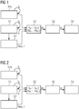
- FIG 1 an embodiment of the computer-implemented method of CM for rotating machines according to the first aspect of the present invention is schematically depicted.
- the method comprises the steps continuously receiving S1 samples of input data, continuously receiving S1a at least one characteristic rotational speed, deriving S1' in-real time samples of an envelope, updating S2 in real-time M accumulator variables, computing S3 in real-time N spectral features and determining S4 a condition.
- samples of input data are continuously received with a predetermined sampling frequency f s .
- the input data is based on two physical quantities, namely the vibrational data is based on a vibration at a bearing of a rotating machine and the electrical data is based on an electrical current provided to the electrical machine.
- the input data is provided by respective sensors, namely the vibrational data is provided by a vibrational sensor measuring the vibrations at the bearing of the rotating machine the electrical data is provided by an electrical sensor measuring the electrical current provided to the electrical machine.
- the input data, i.e. the vibrational data and electrical data are each received as consecutive samples, hence as digital signals.
- a characteristic rotational speed of the rotating machine is continuously received with the predetermined sampling frequency f s .
- the characteristic rotational speed is provided by a rotational speed sensor measuring the current rotational speed of a shaft of the rotating machine.
- the characteristic rotational speed is received as digital signal, i.e. in consecutive samples.
- samples of an envelope are derived from the samples of the input data, i.e. samples of an envelope of the vibrational data and samples of an envelope of the electrical data are derived.
- the samples of the two envelopes are derived either by means of an asynchronous real square law envelope detector 30 (cf. FIG 6 ) or by means of an asynchronous complex IQ envelope detector 40 (cf. FIG 7 ).
- the steps of updating S2 in real-time M accumulator variables and computing S3 in real-time N spectral features are based on the Goertzel Algorithm (GA).
- M accumulator variables are updated in real-time based on L samples.
- the M accumulator variables comprise two previous intermediate sequences sq n-1 , sq n-2 of the vibrational data and the electrical data as well as of the envelopes of the vibrational data and the electrical data.
- the M accumulator variables correspond to the L samples.
- the L samples include a current sample of the vibrational data s v,n and a current sample of the electrical data s e,n as well as a current sample of the envelope of the vibrational data s v,env,n and a current sample of the envelope of the electrical data s e,env,n . Further, the L samples include a first preceding sample of the vibrational data s v,n-1 and a first preceding sample of the electrical data s e,n-1 as well as a first preceding sample of the envelope of the vibrational data s v,env,n-1 and a first preceding sample of the envelope of the electrical data s e,env,n-1 .
- the L samples include a second preceding sample of the vibrational data s v,n-2 and a second preceding sample of the electrical data s e,n-2 as well as a second preceding sample of the envelope of the vibrational data s v,env,n-2 and a second preceding sample of the envelope of the electrical data s e,env,n-2 .
- the first and second preceding samples s v,n-1 , s e,n-1 , s v,env,n-1 , s e,env,n-1 , s v,n-2 , s e,n-2 , s v,env,n-2 , s e,env,n-2 are replaced by the corresponding intermediate sequences sq v,n-1 , sq e,n-1 , sq v,env,n-1 ; sq e,env,n-1 , sq v,n-2 , sq e,n-2 , sq v,env,n-2 , sq e,env,n-2 in the M accumulator variables, where the first and second intermediate sequences have been calculated based on the respective first and second preceding samples.
- N 40 amplitudes of ten first frequencies under investigation ⁇ 0,v,1 to ⁇ 0,v,10 in the vibrational data, ten first frequencies under investigation ⁇ 0,e,1 to ⁇ 0,e,10 in the electrical data, ten second frequencies under investigation ⁇ 0,env,v,1 to ⁇ 0,env,v,10 in the envelope of the vibrational data and ten second frequencies under investigation ⁇ 0,env,v,1 to ⁇ 0,env,v,10 in the envelope of the vibrational data are computed in real-time with the GA.
- FIG 2 a further embodiment of the computer-implemented method of CM for rotating machines according to the first aspect of the present invention is schematically depicted.
- the method comprises the same steps like the method of FIG 1 except that instead of the step S1a the step of determining S1b in real-time the at least one characteristic rotational speed is comprised by the method of FIG 2 . Therefore, only the difference between the two embodiments of FIG 1 and FIG 2 , namely the step S1b, is described in the following.
- the at least one characteristic rotational speed of the rotating machine is determined in real-time based on the vibrational data by means of a real-time Frequency Locked Loop (FLL) method.
- FLL Frequency Locked Loop
- a FFL-analyser (not depicted) is used for determining the characteristic rotational speed in real-time.
- the FFL-analyser comprises an oscillator, a mixer and an analysing block.
- the oscillator generates a digital oscillating signal S' having an oscillating frequency f'.
- the mixer is provided with the digital oscillating signal S' and the samples of the vibrational data and generates a mixed signal S" therefrom.
- the mixed signal S" comprises a first signal part of a sum signal of the frequency of the vibrational signal and the oscillating frequency f' as well as a second signal part of a difference signal of the frequency of the vibrational signal and the oscillating frequency f'.
- the analysing block updates the oscillating frequency f' based on the second signal part including the difference of the frequency of the vibrational signal and the oscillating frequency f' such that the oscillating frequency f' is adjusted to the frequency of the vibrational signal.
- the program steps of the computer program according to the second aspect of the present invention correspond to the method steps of the method according to the first aspect of the present invention and as depicted in Figs 1 to 2 .
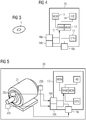
- FIG 3 an embodiment of the computer-readable medium 1 according to the third aspect of the present invention is schematically depicted.
- a computer-readable storage disc 1 like a Compact Disc (CD), Digital Video Disc (DVD), High Definition DVD (HD DVD) or Blu-ray Disc (BD) has stored thereon the computer program according to the second aspect of the present invention and as schematically shown in Figs. 1 to 2 .
- the computer-readable medium may also be a data storage like a magnetic storage/memory (e.g. magnetic-core memory, magnetic tape, magnetic card, magnet strip, magnet bubble storage, drum storage, hard disc drive, floppy disc or removable storage), an optical storage/memory (e.g.
- holographic memory optical tape, Tesa tape, Laserdisc, Phasewriter (Phasewriter Dual, PD) or Ultra Density Optical (UDO)
- magneto-optical storage/memory e.g. MiniDisc or Magneto-Optical Disk (MO-Disk)
- volatile semiconductor/solid state memory e.g. Random Access Memory (RAM), Dynamic RAM (DRAM) or Static RAM (SRAM)
- non-volatile semiconductor/solid state memory e.g. Read Only Memory (ROM), Programmable ROM (PROM), Erasable PROM (EPROM), Electrically EPROM (EEPROM), Flash-EEPROM (e.g. USB-Stick), Ferroelectric RAM (FRAM), Magnetoresistive RAM (MRAM) or Phase-change RAM).
- FIG 4 an embodiment of the data processing system 10 according to the fourth aspect of the present invention is schematically depicted.
- the data processing system 10 may be a personal computer (PC), a laptop, a tablet, a server, a distributed system (e.g. cloud system) and the like.
- the data processing system 10 comprises a central processing unit (CPU) 11, a memory having a random access memory (RAM) 12 and a non-volatile memory (MEM, e.g. hard disk) 13, a human interface device (HID, e.g. keyboard, mouse, touchscreen etc.) 14 and an output device (MON, e.g. monitor, printer, speaker, etc.) 15.
- the data processing system 10 comprises a first interface 16a, a second interface 16b and a third interface 16c.
- the CPU 11, RAM 12, HID 14, MON 15 and the three interfaces 16a, 16b, 16c are communicatively connected via a data bus.
- the RAM 12 and MEM 13 are communicatively connected via another data bus.
- the computer program according to the second aspect of the present invention and schematically depicted in Figs. 1 to 2 can be loaded into the RAM 12 from the MEM 13 or another computer-readable medium 1.
- the vibrational data from the vibrational sensor is received at the first interface 16a and the electrical data from the electrical sensor is received at the second interface 16b.
- the characteristic rotational speed of the rotating machine is received from the rotational speed sensor.
- the CPU 11 executes the steps of the computer-implemented method according to the first aspect of the present invention and as schematically depicted in Figs. 1 to 2 .
- the execution can be initiated and controlled by a user via the HID 14.
- the status and/or result of the executed computer program may be indicated to the user by the MON 15.
- the result of the executed computer program may be permanently stored on the non-volatile MEM 13 or another computer-readable medium.
- the HID 14 and MON 15 for controlling execution of the computer program may be comprised by a different data processing system like a terminal communicatively connected to the data processing system 10 (e.g. cloud system).
- FIG 5 an embodiment of the system according to the fifth aspect of the present invention is schematically depicted.
- the system 20 comprises a rotating machine, here exemplarily an electrical motor 21, a vibrational sensor 22a, an electrical sensor 22b, a rotational speed sensor 22c and the data processing system 10 according to the fourth aspect of the present invention and as depicted in FIG 4 .
- the electrical motor 21 comprises a stator and a rotor with a fixedly attached shaft.
- the rotor with the shaft is pivoted at two points by bearings.
- the electrical motor 21 converts electrical energy provided as electrical current into kinetic energy in form of a rotation with a certain rotational speed and torque.
- the vibrational sensor 22a is arranged near one of the bearings of the electrical motor 21 and communicatively connected to the first interface 16a of the data processing system 10. For converting vibrations into vibrational data the piezoelectric effect or MEMS sensors based on silicon may be used.
- the vibrational sensor 22a measures vibrations of the one of the two bearings and provides the corresponding vibrational data to the first interface 16a.
- the electrical sensor 22b is arranged at the electrical motor 21 and communicatively connected to the second interface 16b of the data processing system 10.
- the electrical sensor 22b measures the electrical current provided to the electrical motor 21 via a resistor and provides the corresponding electrical data to the second interface 16b.
- the rotational speed sensor 22c is arranged at the shaft of the electrical motor 21 and communicatively connected to the third interface 16c of the data processing system 10.
- the rotational speed sensor 22c measures the current rotational speed of the shaft of the electrical motor 21 and provides the corresponding characteristic rotational speed to the third interface 16c.
- vibrational sensor 22a or electrical sensor 22b.
- the rotational speed sensor 22c may be omitted in cases where the rotational speed can be derived from the input data provided by the vibrational sensor 22a and/or the electrical sensor 22b using algorithms or methods like FLL.
- the provided vibrational data, electrical data and characteristic rotational speed is forwarded to the processing means, in particular the RAM 12 and the CPU 11, for executing the steps of the method according to the first aspect of the present invention and as depicted in Figs. 1 and 2 .
- the envelope detector 30 comprises a squaring unit 32, a lowpass filter 34 and a square root unit 35.
- the current samples of the input data 31, here of the vibrational data and the electrical data are first squared in the squaring unit 32, which results in the squared input data 33, and then lowpass-filtered by the lowpass filter 34.
- the output of the low pass filter 34 is provided to the square root unit 35, where the square root is taken.
- the output is the envelope 36 of the input data, here of the vibrational data and the electrical data.
- FIG 7 an asynchronous complex IQ envelope detector 40 is schematically depicted.
- the envelope detector 40 comprises a quadrature power divider 41.
- the input data, the vibrational data and the electrical data is multiplied by sine (In phase - I) and cosine (Quadrature - Q), where ⁇ is the carrier frequency.
- FIG 8 two exemplary diagrams comparing the output of a FFT with the output of the GA are schematically depicted.
- a FFT spectrum crosses
- real-time GA amplitudes for 65 frequencies dots
- a FFT spectrum solid line
- real-time GA amplitudes for 7 the characteristic rotational speed and seven harmonics are exemplarily depicted.
Landscapes
- Physics & Mathematics (AREA)
- General Physics & Mathematics (AREA)
- Engineering & Computer Science (AREA)
- Mathematical Physics (AREA)
- Acoustics & Sound (AREA)
- Theoretical Computer Science (AREA)
- Computational Mathematics (AREA)
- Pure & Applied Mathematics (AREA)
- Mathematical Analysis (AREA)
- Mathematical Optimization (AREA)
- Data Mining & Analysis (AREA)
- Signal Processing (AREA)
- Spectroscopy & Molecular Physics (AREA)
- Chemical & Material Sciences (AREA)
- Software Systems (AREA)
- Databases & Information Systems (AREA)
- Algebra (AREA)
- Health & Medical Sciences (AREA)
- Life Sciences & Earth Sciences (AREA)
- General Engineering & Computer Science (AREA)
- Analytical Chemistry (AREA)
- Biochemistry (AREA)
- General Health & Medical Sciences (AREA)
- Immunology (AREA)
- Pathology (AREA)
- Discrete Mathematics (AREA)
- Testing Of Devices, Machine Parts, Or Other Structures Thereof (AREA)
- Measurement Of Mechanical Vibrations Or Ultrasonic Waves (AREA)
Priority Applications (5)
| Application Number | Priority Date | Filing Date | Title |
|---|---|---|---|
| EP19203532.7A EP3809109A1 (fr) | 2019-10-16 | 2019-10-16 | Analyse intelligente des données d'un moteur à l'aide d'un algorithme en temps réel |
| PCT/EP2020/078110 WO2021073976A1 (fr) | 2019-10-16 | 2020-10-07 | Analyse intelligente de données de moteur avec algorithme en temps réel |
| CN202080072486.3A CN114556070B (zh) | 2019-10-16 | 2020-10-07 | 旋转机器的状况监测的方法、计算机程序、数据处理系统 |
| EP20797376.9A EP4022275B1 (fr) | 2019-10-16 | 2020-10-07 | Analyse intelligente des données d'un moteur à l'aide d'un algorithme en temps réel |
| US17/768,973 US11692866B2 (en) | 2019-10-16 | 2020-10-07 | Smart motor data analytics with real-time algorithm |
Applications Claiming Priority (1)
| Application Number | Priority Date | Filing Date | Title |
|---|---|---|---|
| EP19203532.7A EP3809109A1 (fr) | 2019-10-16 | 2019-10-16 | Analyse intelligente des données d'un moteur à l'aide d'un algorithme en temps réel |
Publications (1)
| Publication Number | Publication Date |
|---|---|
| EP3809109A1 true EP3809109A1 (fr) | 2021-04-21 |
Family
ID=68281157
Family Applications (2)
| Application Number | Title | Priority Date | Filing Date |
|---|---|---|---|
| EP19203532.7A Withdrawn EP3809109A1 (fr) | 2019-10-16 | 2019-10-16 | Analyse intelligente des données d'un moteur à l'aide d'un algorithme en temps réel |
| EP20797376.9A Active EP4022275B1 (fr) | 2019-10-16 | 2020-10-07 | Analyse intelligente des données d'un moteur à l'aide d'un algorithme en temps réel |
Family Applications After (1)
| Application Number | Title | Priority Date | Filing Date |
|---|---|---|---|
| EP20797376.9A Active EP4022275B1 (fr) | 2019-10-16 | 2020-10-07 | Analyse intelligente des données d'un moteur à l'aide d'un algorithme en temps réel |
Country Status (4)
| Country | Link |
|---|---|
| US (1) | US11692866B2 (fr) |
| EP (2) | EP3809109A1 (fr) |
| CN (1) | CN114556070B (fr) |
| WO (1) | WO2021073976A1 (fr) |
Cited By (1)
| Publication number | Priority date | Publication date | Assignee | Title |
|---|---|---|---|---|
| WO2023025392A1 (fr) * | 2021-08-26 | 2023-03-02 | Abb Schweiz Ag | Procédé de surveillance de l'état d'un treuil |
Citations (4)
| Publication number | Priority date | Publication date | Assignee | Title |
|---|---|---|---|---|
| EP2175256A2 (fr) * | 2008-10-07 | 2010-04-14 | General Electric Company | Systèmes et procédés pour la surveillance de machine au niveau de capteurs |
| US20110285532A1 (en) * | 2008-12-22 | 2011-11-24 | S.P.M. Instrument Ab | analysis system |
| EP2581725A2 (fr) * | 2011-10-13 | 2013-04-17 | General Electric Company | Procédés et systèmes de détection de défaut de palier à roulement automatique |
| US20180335366A1 (en) * | 2017-05-19 | 2018-11-22 | Nutech Ventures | Detecting Faults in Wind Turbines |
Family Cites Families (16)
| Publication number | Priority date | Publication date | Assignee | Title |
|---|---|---|---|---|
| US7308322B1 (en) * | 1998-09-29 | 2007-12-11 | Rockwell Automation Technologies, Inc. | Motorized system integrated control and diagnostics using vibration, pressure, temperature, speed, and/or current analysis |
| US7539549B1 (en) * | 1999-09-28 | 2009-05-26 | Rockwell Automation Technologies, Inc. | Motorized system integrated control and diagnostics using vibration, pressure, temperature, speed, and/or current analysis |
| US6751641B1 (en) * | 1999-08-17 | 2004-06-15 | Eric Swanson | Time domain data converter with output frequency domain conversion |
| DE60203458T3 (de) * | 2001-09-27 | 2010-02-18 | Reliance Electric Technologies, LLC, Mayfield Heights | Integrierte Steuerung und Diagnose für ein motorbetriebenes System unter Verwendung von Schwingungs-, Druck-, Temperatur-, Geschwindigkeits-, und/oder Stromanalyse |
| EP4024013A1 (fr) * | 2008-12-22 | 2022-07-06 | S.P.M. Instrument AB | Système d'analyse |
| US9008997B2 (en) * | 2009-10-26 | 2015-04-14 | Fluke Corporation | System and method for vibration analysis and phase analysis of vibration waveforms using dynamic statistical averaging of tachometer data to accurately calculate rotational speed |
| EP2574947A1 (fr) * | 2011-09-30 | 2013-04-03 | ABB Technology AG | Procédé de détermination de signaux stationnaires pour le diagnostic d'un système électromécanique |
| AU2013215672B2 (en) * | 2012-01-30 | 2016-10-20 | S.P.M. Instrument Ab | Apparatus and method for analysing the condition of a machine having a rotating part |
| AU2016209019A1 (en) * | 2015-01-21 | 2017-08-10 | Vayeron Pty Ltd | Improvements in conveyor and components therefor, monitoring methods and communication systems |
| GB2543521A (en) * | 2015-10-20 | 2017-04-26 | Skf Ab | Method and data processing device for severity assessment of bearing defects using vibration energy |
| US10227937B2 (en) * | 2015-11-04 | 2019-03-12 | Ge Global Sourcing Llc | Methods and system for a turbocharger |
| AU2017206138A1 (en) * | 2016-07-18 | 2018-02-01 | Vayeron Technologies Pty Ltd | Improvements In Rotating Shaft and Component Monitoring, Methods and Communications Systems Therefor |
| DE102017216666A1 (de) * | 2017-09-20 | 2019-03-21 | Dr. Johannes Heidenhain Gmbh | Positionsmesseinrichtung und Verfahren zum Betreiben einer Positionsmesseinrichtung |
| US10746590B2 (en) | 2017-09-29 | 2020-08-18 | Rockwell Automation Technologies, Inc. | Method and apparatus for online condition monitoring of variable speed motor applications |
| DE102018206435A1 (de) * | 2018-04-25 | 2019-10-31 | Aktiebolaget Skf | Vorrichtung zum Bestimmen einer Drehgeschwindigkeit und einer Schwingung eines Radkopfs eines Fahrzeugs |
| CN110160791B (zh) * | 2019-06-27 | 2021-03-23 | 郑州轻工业学院 | 基于小波-谱峭度的感应电机轴承故障诊断系统及诊断方法 |
-
2019
- 2019-10-16 EP EP19203532.7A patent/EP3809109A1/fr not_active Withdrawn
-
2020
- 2020-10-07 EP EP20797376.9A patent/EP4022275B1/fr active Active
- 2020-10-07 US US17/768,973 patent/US11692866B2/en active Active
- 2020-10-07 WO PCT/EP2020/078110 patent/WO2021073976A1/fr unknown
- 2020-10-07 CN CN202080072486.3A patent/CN114556070B/zh active Active
Patent Citations (4)
| Publication number | Priority date | Publication date | Assignee | Title |
|---|---|---|---|---|
| EP2175256A2 (fr) * | 2008-10-07 | 2010-04-14 | General Electric Company | Systèmes et procédés pour la surveillance de machine au niveau de capteurs |
| US20110285532A1 (en) * | 2008-12-22 | 2011-11-24 | S.P.M. Instrument Ab | analysis system |
| EP2581725A2 (fr) * | 2011-10-13 | 2013-04-17 | General Electric Company | Procédés et systèmes de détection de défaut de palier à roulement automatique |
| US20180335366A1 (en) * | 2017-05-19 | 2018-11-22 | Nutech Ventures | Detecting Faults in Wind Turbines |
Cited By (1)
| Publication number | Priority date | Publication date | Assignee | Title |
|---|---|---|---|---|
| WO2023025392A1 (fr) * | 2021-08-26 | 2023-03-02 | Abb Schweiz Ag | Procédé de surveillance de l'état d'un treuil |
Also Published As
| Publication number | Publication date |
|---|---|
| EP4022275A1 (fr) | 2022-07-06 |
| US20220357194A1 (en) | 2022-11-10 |
| EP4022275B1 (fr) | 2022-12-21 |
| US11692866B2 (en) | 2023-07-04 |
| CN114556070B (zh) | 2024-08-27 |
| CN114556070A (zh) | 2022-05-27 |
| WO2021073976A1 (fr) | 2021-04-22 |
Similar Documents
| Publication | Publication Date | Title |
|---|---|---|
| US10495693B2 (en) | Wind turbine fault detection using acoustic, vibration, and electrical signals | |
| Cao et al. | Vibration signal correction of unbalanced rotor due to angular speed fluctuation | |
| US5521482A (en) | Method and apparatus for determining mechanical performance of polyphase electrical motor systems | |
| CN103502827B (zh) | 用于监测机电系统的状况方法和设备 | |
| US8291764B2 (en) | Method and apparatus for in situ unbalance and corrective balance determination for a non-vertical axis rotating assembly | |
| JP5670033B2 (ja) | 漂遊磁束を処理する方法およびシステム | |
| EP2942867A2 (fr) | Estimation de la vitesse d'un moteur à induction | |
| DK2761315T3 (en) | METHOD FOR DETERMINING STATIONARY SIGNALS FOR DIAGNOSTICATION OF AN ELECTROMECHANICAL SYSTEM | |
| Climente-Alarcon et al. | Particle filter-based estimation of instantaneous frequency for the diagnosis of electrical asymmetries in induction machines | |
| RU2431152C2 (ru) | Способ диагностики механизмов и систем с электрическим приводом | |
| Corne et al. | Comparing MCSA with vibration analysis in order to detect bearing faults—A case study | |
| KR20230054455A (ko) | 기계 상태 모니터링 방법 및 기계 상태 모니터링 시스템 | |
| EP4022275B1 (fr) | Analyse intelligente des données d'un moteur à l'aide d'un algorithme en temps réel | |
| CN117606782B (zh) | 风力发电机叶片故障检测方法、装置、设备及存储介质 | |
| Gritli et al. | Diagnosis of mechanical unbalance for double cage induction motor load in time-varying conditions based on motor vibration signature analysis | |
| JPH07324974A (ja) | 回転機振動診断装置 | |
| JP4688097B2 (ja) | 風力発電機の運転状態判別方法 | |
| EP2556381B1 (fr) | Estimation de la vitesse et de la position du rotor de machines électriques en utilisant des harmoniques des rainures de rotor ou des harmoniques d'ordre supérieur | |
| US20200408840A1 (en) | Health monitor circuit for an electric machine | |
| JP2021052441A (ja) | 設備診断装置、設備診断方法、及び設備診断プログラム | |
| Zhou et al. | A Fast Tacho-Less Order Tracking Method for Gear Fault Diagnosis Under Large Rotational Speed Variation Conditions Based on Multi-stage Generalized Demodulation | |
| Mones et al. | Fault Detection of Planetary Gearboxes using a Wireless MEMS Sensor and New Diagnostic Parameters | |
| Etien et al. | A Tacholess order Analysis Method for PMSG Mechanical Fault Detection with Varying Speeds. Electronics 2021, 10, 418 | |
| Stiller et al. | Comparison of different noise analysis methods for error detection on induction machines | |
| Kuttner et al. | Signal Analysis Methods and Examples |
Legal Events
| Date | Code | Title | Description |
|---|---|---|---|
| PUAI | Public reference made under article 153(3) epc to a published international application that has entered the european phase |
Free format text: ORIGINAL CODE: 0009012 |
|
| STAA | Information on the status of an ep patent application or granted ep patent |
Free format text: STATUS: THE APPLICATION HAS BEEN PUBLISHED |
|
| AK | Designated contracting states |
Kind code of ref document: A1 Designated state(s): AL AT BE BG CH CY CZ DE DK EE ES FI FR GB GR HR HU IE IS IT LI LT LU LV MC MK MT NL NO PL PT RO RS SE SI SK SM TR |
|
| AX | Request for extension of the european patent |
Extension state: BA ME |
|
| STAA | Information on the status of an ep patent application or granted ep patent |
Free format text: STATUS: THE APPLICATION IS DEEMED TO BE WITHDRAWN |
|
| 18D | Application deemed to be withdrawn |
Effective date: 20211022 |