EP3809035A1 - Sicherheitssystem mit einem sicherheitsschalter - Google Patents
Sicherheitssystem mit einem sicherheitsschalter Download PDFInfo
- Publication number
- EP3809035A1 EP3809035A1 EP20197865.7A EP20197865A EP3809035A1 EP 3809035 A1 EP3809035 A1 EP 3809035A1 EP 20197865 A EP20197865 A EP 20197865A EP 3809035 A1 EP3809035 A1 EP 3809035A1
- Authority
- EP
- European Patent Office
- Prior art keywords
- control
- electromagnet
- evaluation unit
- signal
- protective device
- Prior art date
- Legal status (The legal status is an assumption and is not a legal conclusion. Google has not performed a legal analysis and makes no representation as to the accuracy of the status listed.)
- Granted
Links
Images




Classifications
-
- F—MECHANICAL ENGINEERING; LIGHTING; HEATING; WEAPONS; BLASTING
- F16—ENGINEERING ELEMENTS AND UNITS; GENERAL MEASURES FOR PRODUCING AND MAINTAINING EFFECTIVE FUNCTIONING OF MACHINES OR INSTALLATIONS; THERMAL INSULATION IN GENERAL
- F16P—SAFETY DEVICES IN GENERAL; SAFETY DEVICES FOR PRESSES
- F16P3/00—Safety devices acting in conjunction with the control or operation of a machine; Control arrangements requiring the simultaneous use of two or more parts of the body
- F16P3/08—Safety devices acting in conjunction with the control or operation of a machine; Control arrangements requiring the simultaneous use of two or more parts of the body in connection with the locking of doors, covers, guards, or like members giving access to moving machine parts
-
- F—MECHANICAL ENGINEERING; LIGHTING; HEATING; WEAPONS; BLASTING
- F16—ENGINEERING ELEMENTS AND UNITS; GENERAL MEASURES FOR PRODUCING AND MAINTAINING EFFECTIVE FUNCTIONING OF MACHINES OR INSTALLATIONS; THERMAL INSULATION IN GENERAL
- F16P—SAFETY DEVICES IN GENERAL; SAFETY DEVICES FOR PRESSES
- F16P3/00—Safety devices acting in conjunction with the control or operation of a machine; Control arrangements requiring the simultaneous use of two or more parts of the body
- F16P3/12—Safety devices acting in conjunction with the control or operation of a machine; Control arrangements requiring the simultaneous use of two or more parts of the body with means, e.g. feelers, which in case of the presence of a body part of a person in or near the danger zone influence the control or operation of the machine
- F16P3/14—Safety devices acting in conjunction with the control or operation of a machine; Control arrangements requiring the simultaneous use of two or more parts of the body with means, e.g. feelers, which in case of the presence of a body part of a person in or near the danger zone influence the control or operation of the machine the means being photocells or other devices sensitive without mechanical contact
- F16P3/145—Safety devices acting in conjunction with the control or operation of a machine; Control arrangements requiring the simultaneous use of two or more parts of the body with means, e.g. feelers, which in case of the presence of a body part of a person in or near the danger zone influence the control or operation of the machine the means being photocells or other devices sensitive without mechanical contact using magnetic technology
-
- F—MECHANICAL ENGINEERING; LIGHTING; HEATING; WEAPONS; BLASTING
- F16—ENGINEERING ELEMENTS AND UNITS; GENERAL MEASURES FOR PRODUCING AND MAINTAINING EFFECTIVE FUNCTIONING OF MACHINES OR INSTALLATIONS; THERMAL INSULATION IN GENERAL
- F16P—SAFETY DEVICES IN GENERAL; SAFETY DEVICES FOR PRESSES
- F16P3/00—Safety devices acting in conjunction with the control or operation of a machine; Control arrangements requiring the simultaneous use of two or more parts of the body
- F16P3/12—Safety devices acting in conjunction with the control or operation of a machine; Control arrangements requiring the simultaneous use of two or more parts of the body with means, e.g. feelers, which in case of the presence of a body part of a person in or near the danger zone influence the control or operation of the machine
- F16P3/14—Safety devices acting in conjunction with the control or operation of a machine; Control arrangements requiring the simultaneous use of two or more parts of the body with means, e.g. feelers, which in case of the presence of a body part of a person in or near the danger zone influence the control or operation of the machine the means being photocells or other devices sensitive without mechanical contact
- F16P3/147—Safety devices acting in conjunction with the control or operation of a machine; Control arrangements requiring the simultaneous use of two or more parts of the body with means, e.g. feelers, which in case of the presence of a body part of a person in or near the danger zone influence the control or operation of the machine the means being photocells or other devices sensitive without mechanical contact using electro-magnetic technology, e.g. tags or radar
-
- F—MECHANICAL ENGINEERING; LIGHTING; HEATING; WEAPONS; BLASTING
- F16—ENGINEERING ELEMENTS AND UNITS; GENERAL MEASURES FOR PRODUCING AND MAINTAINING EFFECTIVE FUNCTIONING OF MACHINES OR INSTALLATIONS; THERMAL INSULATION IN GENERAL
- F16P—SAFETY DEVICES IN GENERAL; SAFETY DEVICES FOR PRESSES
- F16P3/00—Safety devices acting in conjunction with the control or operation of a machine; Control arrangements requiring the simultaneous use of two or more parts of the body
- F16P3/12—Safety devices acting in conjunction with the control or operation of a machine; Control arrangements requiring the simultaneous use of two or more parts of the body with means, e.g. feelers, which in case of the presence of a body part of a person in or near the danger zone influence the control or operation of the machine
- F16P3/14—Safety devices acting in conjunction with the control or operation of a machine; Control arrangements requiring the simultaneous use of two or more parts of the body with means, e.g. feelers, which in case of the presence of a body part of a person in or near the danger zone influence the control or operation of the machine the means being photocells or other devices sensitive without mechanical contact
- F16P3/148—Safety devices acting in conjunction with the control or operation of a machine; Control arrangements requiring the simultaneous use of two or more parts of the body with means, e.g. feelers, which in case of the presence of a body part of a person in or near the danger zone influence the control or operation of the machine the means being photocells or other devices sensitive without mechanical contact using capacitive technology
Definitions
- Safety switch is a commonly used and synonymous name for a locking device or locking unit with tumbler according to the EN ISO 14119 standard.
- machines are used that can be dangerous for people. Examples of such machines are presses or robots that carry out movements that are dangerous for humans. These areas are protected by mechanical fences or light grids, for example.
- movable protective devices for example doors, which are provided with safety switches. If the door is opened, the safety switch switches off the machine.
- Such safety switches also have a tumbler so that the door is blocked and cannot be opened at all.
- the guard locking can only be deactivated by a stop command on the door or on the central human-machine interface (HMI) of the machine in order to gain access to the danger area, whereby the dangerous movement is switched off.
- HMI central human-machine interface
- the doors on machines serve as protective devices, namely as movable protective devices in the sense of the Machinery Directive.
- the door is monitored and locked using safety switches with guard locking available on the market. It is, for example, a type 2 or a type 4 known according to the ISO 14119 standard.
- these switches are based on a mechanical principle, e.g. B. the safety switch i10Lock from SICK or, for example, on RFID technology such as the safety switch with guard locking TR10 Lock or MLP1 from SICK.
- One object of the invention is to provide an improved safety system with an improved safety switch, the aim being to ensure that the safety switch is closed or open.
- a safety system with a safety switch for monitoring a safe protective device status of a movable protective device with a base housing consisting of at least two sub-bodies that can be positioned relative to one another, with a signal receiver in one sub-body and a signal transmitter in the other Partial bodies are provided so that a safe state of the protective device can be detected by means of a control and evaluation unit, and a locking unit with an electromagnet and a holding plate, which is opposite the electromagnet, for locking or unlocking the protective device, the control and evaluation unit being designed to unlock or lock the locking unit after checking and verification of the signal receiver, characterized in that a coil of the electromagnet forms an oscillating circuit with a capacitor, the oscillating circuit being controlled by the control - and evaluation unit is cyclically acted upon with at least one pulse signal and the impulse response is evaluated by the control and evaluation unit and depending on the impulse response at least one contact or non-contact between the electromagnet and the holder plate can be detected.
- a negative pulse signal is applied to the coil in the activated state in which the coil is operated and supplied with voltage.
- the coil is supplied with a voltage of 24 V.
- the supply voltage of the coil is cyclically switched off or interrupted for a short period of time, for example 5 ms.
- the shutdown or interruption of the voltage supply takes place cyclically, for example at intervals of 500 ms, so that the operation of the electromagnet is not impaired by the coil.
- the pulse signal can also be referred to as a test pulse or test gap.
- the cyclical interruption or shutdown of the supply voltage takes place electronically, for example with an electronic switch.
- the electronic Switch can be, for example, a transistor, a transistor stage or the like.
- the cyclical interruption is controlled by the control and evaluation unit, for example controlled by an output stage or the transistor.
- the impulse response or step response or impulse function or step function of the resonant circuit is evaluated by the control and evaluation unit.
- the resonant circuit preferably has a low level of damping, so that the step response exhibits an evaluable transient response, depending on the holding plate in the vicinity of or in contact with the electromagnet.
- the curve shape of the transient behavior changes depending on the proximity or when the holding plate comes into contact with the electromagnet, since the coil of the electromagnet is influenced electromagnetically by the metal holding plate.
- the capacitor in the resonant circuit is discharged faster during the pulse duration, for example, so that the step response forms a charging curve of the capacitor with a short time constant.
- the capacitor in the resonant circuit is, for example, discharged less quickly during the pulse duration, so that the step response is a charging curve with a longer time constant.
- the capacitor in the resonant circuit is discharged the slowest during the pulse duration, so that the step response is a charging curve with an even longer time constant.
- the edge steepness of the step response or a comparison of the step response with a comparison value or a threshold value can be compared.
- the step response is evaluated, for example, via a simple transistor circuit or a transistor stage, which is evaluated by the control and evaluation unit.
- the resonant circuit is a parallel resonant circuit.
- the coil of the electromagnet is parallel to the capacitor.
- the parallel resonant circuit has the property that when there is resonance, the resistance that can be observed at the terminals approaches infinity.
- the parallel resonant circuit has the advantage that the coil or the electromagnet can be operated statically and the capacitor has virtually no effect in the static operating mode because it is charged and thus forms an almost infinitely high resistance.
- a damping factor ⁇ of the resonant circuit is at most 0.3 and in particular at most 0.2. In this way, an oscillating circuit is used which has a high level of overshoot behavior. In this way, steep edges of the impulse response are generated during the short switch-off impulses or voltage impulses, which are easy to evaluate.
- the pulse width depends on the electromagnet, in particular on the inductance of the coil and the capacitance of the capacitor. In a further development of the invention, the pulse width is a maximum of 6 ms, in particular a maximum of 5 ms, the pulses being spaced apart by at least 400 ms, in particular at least 500 ms. This means that the pulse width does not lead to a functional restriction of the electromagnet in the active state with applied voltage. Furthermore, the pulse width or pulse length is long enough to be able to carry out a simple evaluation. The control and evaluation unit can thus be designed simply and inexpensively.
- an NPN transistor or an NPN transistor stage is arranged for evaluating the impulse response.
- the NPN transistor is arranged, for example, in an emitter circuit.
- the voltage of the electromagnet is fed as an input signal to the NPN transistor via a voltage divider.
- the collector connection is connected to a reference potential of, for example, 3.3 or 5 volts via a resistor.
- the emitter connection is connected to ground.
- the collector is connected to the control and evaluation unit as a signal output.
- a decreasing voltage of the impulse response at the base connection leads to the transistor being blocked and thus to a positive digitized voltage signal at the output of the transistor, namely the collector-emitter path of the transistor.
- the positive output signal of the transistor is longer the slower the capacitor is charged or the longer the time constant.
- the detection of the signal generator by the signal receiver and the detection of the holding plate by means of the pulse evaluation form two diverse signal sources, whereby a diverse and redundant signal evaluation is provided which fulfills a high level of security.
- the safety switch can meet a safety integrity level of up to SIL3 according to IEC61508 / IEC61511.
- the signal transmitter and the signal receiver are designed as an RFID system with an RFID transponder and an RFID reader.
- the RFID transponder is arranged on the first part of the body on which the holding plate is arranged. The first part of the body thus forms a passive component without its own power supply.
- the RFID reader is arranged on the second part of the body on which the electromagnet is also arranged.
- the second part of the body forms an active component with a connection for signal lines and a voltage supply.
- the RFID reader can be used to determine whether the RFID transponder is in the vicinity of the RFID reader. This makes it possible to determine whether the first part body is in the vicinity of the second part body.
- FIG Figure 8 shows a system 19 with a robot 20 and a danger area 21.
- a safety system 1 is arranged with a safety switch 2 for monitoring a safe protective device status of a movable protective device 3, with a base housing 4, which consists of at least two sub-bodies 5 and 6, which can be positioned relative to one another
- system 19 it can be according to Figure 8 for example an industrial plant for the manufacture of products.
- the system 19 can also be part of a machine or a system 19 with several machines.
- the system 19 has a danger area 21 or safety area which may not be entered by persons 22 when the system 19 is active, since the person 22 can be endangered by parts of the system 19.
- one or more robots 20 are arranged in the system 19, the dangerous area of action of which lies within the danger area 21.
- the movable protective device 3 can be a door or a gate or the like for securing a danger area.
- Figure 1 shows a safety system 1 with a safety switch 2 for monitoring a safe protective device state of a movable protective device, with a base housing 4, which consists of at least two sub-bodies 5 and 6, which can be positioned relative to one another, with a signal receiver 7 in a second sub-body 6 and a signal transmitter 8 are provided in the other first partial body 5 so that a safe state of the protective device can be detected by means of a control and evaluation unit 9, and a locking unit 10 with an electromagnet 11 and a retaining plate 12, which is opposite the electromagnet 11, for locking or unlocking the Protection device, wherein the control and evaluation unit 9 is designed to unlock or lock the locking unit 10 after checking and verification of the signal receiver 7, characterized in that a coil 13 of the electromagnet 11 forms an oscillating circuit 15 with a capacitor, d he oscillating circuit 15 from the control and evaluation unit 9 cyclically with at least an impulse signal is applied and the impulse response is evaluated by the control and evaluation unit 9 and, depending on the impulse response, at least one contact
- a negative pulse signal is applied.
- the coil 13 is supplied with a voltage of 24 V.
- the supply voltage of the coil 13 is cyclically switched off or interrupted for a short period of time, for example 5 ms.
- the shutdown or interruption of the voltage supply takes place cyclically, for example at intervals of 500 ms, so that the operation of the electromagnet 11 is not impaired by the coil 13.
- the pulse signal can also be referred to as a test pulse or test gap.
- the cyclical interruption or disconnection of the supply voltage VDD, which is specified in Figure 3 is shown takes place electronically, for example with an electronic switch.
- the electronic switch can be, for example, a transistor, a transistor stage or the like.
- the cyclical interruption is controlled by the control and evaluation unit 9, according to Figure 1 , controlled for example via an output stage or the transistor.
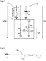
- the resonant circuit 15 off Figure 1 is in Figure 2 shown in more detail.
- Figure 2 shows the supply voltage VDD, the step response VS and the output signal VA.
- the impulse response or step response VS or the impulse function or step function of the resonant circuit, which is shown in Figure 4 is shown is evaluated by the control and evaluation unit 9.
- the resonant circuit 15 preferably has a low damping, so that the step response VS shows an evaluable transient behavior, depending on the holding plate 12 in the vicinity or in contact with the electromagnet 11.
- the curve shape of the transient behavior changes depending on the proximity or at one Contact of the holding plate 12 with the electromagnet 11, since the coil 13 of the electromagnet 11 is electromagnetically influenced by the metallic holding plate 12.
- Figure 5 shows the step response VS and a digitized output signal VA for the case that there is no holding plate in the vicinity of the electromagnet.
- the digitized The output signal VA is formed on the basis of a threshold value comparison with the step response VS and is evaluated by the control and evaluation unit 9. As soon as the signal of the step response VS falls below a certain level, the output signal VA has a positive level.
- the output signal VA thus has a first longer pulse and a second shorter pulse according to FIG Figure 5 .
- the capacitor 14 in the resonant circuit 15 according to FIG Figure 2 discharged faster during the pulse duration, for example, so that the step response VS forms a charging curve of the capacitor 14 with a short time constant, according to FIG Figure 5 .
- control and evaluation unit 9 which is designed, for example, as a microcontroller, triggers the 5 ms long pulse at intervals of 500 ms and monitors the output signal VA or the output voltage.
- the control and evaluation unit 9 or the microcontroller checks the output signal VA, for example via polling using software or using an interrupt routine using software or hardware.
- Figure 6 shows the step response VS and a digitized output signal VA for the case that the holding plate 12 is in the vicinity of the electromagnet 11.
- the digitized output signal VA is formed on the basis of a threshold value comparison with the step response VS and is evaluated by the control and evaluation unit 9. As soon as the signal of the step response VS falls below a certain level, the output signal VA has a positive level.
- the first longer pulse of the output signal VA is shown in FIG Figure 6 compared to the output signal VA according to Figure 5 extended.
- the capacitor 14 in the resonant circuit 15 according to FIG Figure 2 discharged less quickly during the pulse duration, for example, so that the step response VS is a charging curve with a longer time constant, according to FIG Figure 6 .
- the capacitor 14 in the resonant circuit 15 is, for example, discharged the slowest during the pulse duration, so that the step response VS is a charging curve with an even longer time constant, according to FIG Figure 7 .
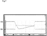
- Figure 7 shows the step response VS and a digitized output signal VA for the case that the holding plate 12 is in contact with the electromagnet 11.
- the digitized output signal VA is also formed on the basis of a threshold value comparison with the step response VS and is evaluated by the control and evaluation unit 9 according to FIG. As soon as the signal of the step response VS falls below a certain level, the output signal VA has a positive level.
- the first longer pulse of the output signal VA is shown in FIG Figure 7 , across from Figure 6 extended and only a single longer signal.
- control and evaluation unit 9 detects the contact between the electromagnet 11 and the holding plate 12, for example, no more pulse signal 18 is generated by the control and evaluation unit 9 and a continuous supply voltage VDD of, for example, 24 volts is applied to the electromagnet 11 without interruptions.
- control and evaluation unit 9 can again cyclically apply the pulse signal 18 to the electromagnet 11 in order to again detect contact with the holding plate 12.
- the edge steepness of the step response VS or a comparison of the step response VS can be compared with a comparison value or a threshold value.
- the step response VS is evaluated, for example, via a simple transistor circuit according to FIG Figure 2 or a transistor stage which is evaluated by the control and evaluation unit 9.
- the resonant circuit 15 is a parallel resonant circuit.
- the coil 13 of the electromagnet 11 lies parallel to the capacitor 14.
- the parallel resonant circuit has the advantage that the coil 13 or the electromagnet 11 can be operated statically and the capacitor 14 has virtually no effect in the static operating mode because it is charged and thus forms an almost infinitely high resistance.
- a damping factor ⁇ of the resonant circuit 15 is, for example, at most 0.3 and in particular at most 0.2.
- a resonant circuit 15 with a high quality is thus formed. In this way, steep edges of the impulse response are generated during the short switch-off impulses or voltage impulses, which can be easily evaluated according to the Figures 5 to 7 .
- the pulse width is a maximum of 6 ms, in particular a maximum of 5 ms, the pulses being spaced apart by at least 400 ms, in particular at least 500 ms.
- the pulse width does not lead to a functional restriction of the electromagnet 11 in the active state with applied voltage.
- the pulse width or pulse length is long enough to be able to carry out a simple evaluation.
- an NPN transistor 16 is arranged for evaluating the impulse response.
- the NPN transistor 16 is arranged in an emitter circuit.
- the voltage of the electromagnet 11 is fed as an input signal to the NPN transistor via a voltage divider.
- the collector connection is connected to a reference potential of 3.3 V, for example, via a resistor.
- the emitter connection is connected to ground.
- the collector is as a signal output with the control and evaluation unit 9 according to Figure 1 connected.
- a decreasing voltage of the step response VS at the base connection leads to the transistor 16 being blocked and thus to a positive digitized voltage signal or output signal VA at the output of the transistor 16, namely the collector-emitter path of the transistor 16.
- the positive output signal VA of the transistor 16 is longer the slower the capacitor 14 is charged or the longer the time constant, according to FIGS Figures 5 to 7 .
- a simple digital output signal VA can thus be evaluated by the control and evaluation unit 9 at the output of the transistor 16 or the transistor stage.
- the signal transmitter 8 and the signal receiver 7 are designed, for example, as an RFID system with an RFID transponder and an RFID reader.
- the RFID transponder is arranged on the first part of the body 5 on which the holding plate is located is arranged.
- the first partial body 5 thus forms a passive component without its own power supply.
- the RFID reader is arranged on the second partial body 6 on which the electromagnet 11 is also arranged.
- the second partial body 6 forms an active component with a connection for signal lines and a voltage supply.
- the RFID reader can be used to determine whether the RFID transponder is in the vicinity of the RFID reader. This makes it possible to determine whether the first part body 5 is in the vicinity of the second part body 6.
Landscapes
- Engineering & Computer Science (AREA)
- General Engineering & Computer Science (AREA)
- Mechanical Engineering (AREA)
- Radar, Positioning & Navigation (AREA)
- Remote Sensing (AREA)
- Electronic Switches (AREA)
Abstract
Description
- Die vorliegende Erfindung betrifft ein Sicherheitssystem mit einem Sicherheitsschalter nach dem Oberbegriff von Anspruch 1. Sicherheitsschalter ist eine marktübliche und synonyme Bezeichnung für Verriegelungseinrichtung oder Verriegelungseinheit mit Zuhaltung gemäß der Norm EN ISO 14119.
- In der Industrie werden Maschinen eingesetzt, die für Menschen gefährlich sein können. Beispiele für solche Maschinen sind Pressen oder Roboter, die für den Menschen gefahrbringende Bewegungen ausführen. Diese Bereiche werden beispielsweise durch mechanische Zäune oder Lichtgitter abgesichert. Um dennoch in den Bereich der gefährlichen Maschine zu gelangen zu können, sind bewegliche Schutzeinrichtungen, beispielsweise Türen vorgesehen, die mit Sicherheitsschaltern versehen sind. Wird die Tür geöffnet, sorgt der Sicherheitsschalter für eine Abschaltung der Maschine.
- Derartige Sicherheitsschalter weisen weiter eine Zuhaltung auf, so dass die Türe blockiert ist und gar nicht geöffnet werden kann. Lediglich durch einen Stoppbefehl an der Türe oder an dem zentralen Mensch-Maschinen-Interfache (HMI) der Maschine kann die Zuhaltung deaktiviert werden, um Zutritt zu dem Gefahrenbereich zu erhalten, wobei die gefahrbringende Bewegung abgeschaltet wird. Bei nachlaufenden Maschinen bzw. Prozessen muss die Türe so lange zugehalten werden, bis die Gefahr in der Maschine nicht mehr besteht.
- Die Türen an Maschinen dienen als Schutzeinrichtung, nämlich als bewegliche Schutzeinrichtung im Sinne der Maschinenrichtlinie.
- Die Überwachung und Zuhaltung der Türe wird mit am Markt verfügbaren Sicherheitsschaltern mit Zuhaltung realisiert. Es ist beispielsweise eine Bauart 2 bzw. eine Bauart 4 nach der Norm ISO 14119 bekannt. Diese Schalter basieren zum einen auf mechanischem Prinzip, z. B. der Sicherheitsschalter i10Lock von der Firma SICK oder beispielsweise auf RFID Technologie wie der Sicherheitsschalter mit Zuhaltung TR10 Lock oder MLP1 der Fa. SICK.
- Eine Aufgabe der Erfindung besteht darin, ein verbessertes Sicherheitssystem mit einem verbesserten Sicherheitsschalter bereitzustellen, wobei gewährleistet soll, dass der Sicherheitsschalter geschlossen oder geöffnet ist.
- Die Aufgabe wird gemäß Anspruch 1 gelöst durch ein Sicherheitssystem mit einem Sicherheitsschalter zum Überwachen eines sicheren Schutzeinrichtungszustandes einer beweglichen Schutzeinrichtung, mit einem Grundgehäuse, das aus zumindest zwei Teilkörpern besteht, die zueinander positionierbar sind, wobei ein Signalempfänger in einem Teilkörper und ein Signalgeber in dem anderen Teilkörper vorgesehen sind, so dass ein sicherer Zustand der Schutzeinrichtung mittels einer Steuer- und Auswerteeinheit erfassbar ist, und einer Verriegelungseinheit mit einem Elektromagnet und einer Halteplatte, welche dem Elektromagnet gegenüberliegt, zum Verriegeln oder Entriegeln der Schutzeinrichtung, wobei die Steuer- und Auswerteeinheit ausgebildet ist, nach Überprüfung und Verifikation des Signalempfängers die Verriegelungseinheit zu entriegeln oder verriegeln, dadurch gekennzeichnet, dass eine Spule des Elektromagneten mit einem Kondensator einen Schwingkreis bildet, wobei der Schwingkreis von der Steuer- und Auswerteeinheit zyklisch mit mindestens einem Impulssignal beaufschlagt wird und die Impulsantwort von der Steuer- und Auswerteeinheit ausgewertet wird und abhängig von der Impulsantwort mindestens ein Kontakt oder ein Nichtkontakt zwischen dem Elektromagnet und der Halterplatte erfassbar ist.
- Gemäß der Erfindung wird die Spule im aktivierten Zustand, in dem die Spule betrieben und mit Spannung versorgt ist, mit einem negativen Impulssignal beaufschlagt. Beispielsweise wird die Spule mit einer Spannung von 24 V versorgt. Beispielsweise wird hierzu die Versorgungsspannung der Spule für eine kurze Zeitdauer, beispielsweise 5 ms zyklisch abgeschaltet bzw. unterbrochen. Die Abschaltung bzw. Unterbrechung der Spannungsversorgung findet zyklisch beispielsweise mit Abständen von 500 ms statt, so dass der Betrieb des Elektromagneten durch die Spule nicht beeinträchtigt wird. Das Impulssignal kann auch als Testpuls bzw. Testlücke bezeichnet werden.
- Die zyklische Unterbrechung bzw. Abschaltung der Versorgungsspannung erfolgt elektronisch, beispielsweise mit einem elektronischen Schalter. Bei dem elektronischen Schalter kann es sich beispielsweise um einen Transistor, eine Transistorstufe oder ähnliches handeln. Die zyklische Unterbrechung wird von der Steuer- und Auswerteeinheit gesteuert, beispielsweise über eine Ausgangsstufe oder den Transistor gesteuert.
- Die Impulsantwort bzw. Sprungantwort oder Impulsfunktion bzw. Sprungfunktion des Schwingkreises wird von der Steuer- und Auswerteeinheit ausgewertet. Vorzugsweise weist der Schwingkreis dabei eine geringe Dämpfung auf, so dass die Sprungantwort ein auswertbares Einschwingverhalten zeigt, abhängig von der Halteplatte in der Nähe oder in Kontakt mit dem Elektromagneten. Die Kurvenform des Einschwingverhaltens ändert sich je nach Nähe bzw. bei einem Kontakt der Halteplatte mit dem Elektromagneten, da die Spule des Elektromagneten durch die metallische Halteplatte elektromagnetisch beeinflusst wird.
- Ohne Halteplatte wird der Kondensator im Schwingkreis während der Pulsdauer beispielsweise schneller entladen, so dass die Sprungantwort eine Ladekurve des Kondensators mit einer kurzen Zeitkonstanten bildet.
- Ist die Halteplatte wenige Millimeter von dem Elektromagnet entfernt so wird der Kondensator im Schwingkreis während der Pulsdauer beispielsweise weniger schnell entladen, so dass die Sprungantwort eine Ladekurve mit einer längeren Zeitkonstanten ist.
- Ist die Halteplatte in Kontakt, bzw. in elektrischem Kontakt mit dem Elektromagnet, so wird der Kondensator im Schwingkreis während der Pulsdauer beispielsweise am langsamsten entladen, so dass die Sprungantwort eine Ladekurve mit einer noch längeren Zeitkonstanten ist.
- Gemäß der Erfindung kann beispielsweise die Flankensteilheit der Sprungantwort oder ein Vergleich der Sprungantwort mit einem Vergleichswert bzw. einem Schwellwert verglichen werden.
- Die Auswertung der Sprungantwort erfolgt beispielsweise über eine einfache Transistorschaltung bzw. eine Transistorstufe, welche von der Steuer- und Auswerteeinheit ausgewertet wird.
- In Weiterbildung der Erfindung ist der Schwingkreis ein Parallelschwingkreis. Dabei liegt die Spule des Elektromagneten parallel zu dem Kondensator. Der Parallelschwingkreis hat die Eigenschaft, dass bei Resonanz der an den Klemmen beobachtbare Widerstand gegen unendlich geht.
- Der Parallelschwingkreis hat den Vorteil, dass die Spule bzw. der Elektromagnet statisch betrieben werden kann und der Kondensator im statischen Betriebsmodus quasi keine Auswirkung hat da dieser geladen ist und damit einen nahezu unendlich hohen Widerstand bildet.
- In Weiterbildung der Erfindung beträgt ein Dämpfungsfaktor ξ des Schwingkreises höchstens 0,3 und insbesondere höchstens 0,2. Damit wird ein Schwingkreis verwendet, welcher ein hohes Überschwingverhalten aufweist. Damit werden während der kurzen Abschaltungsimpulsen bzw. Spannungsimpulsen steile Flanken der Impulsantwort erzeugt die einfach auszuwerten sind.
- Die Pulsbreite hängt vom Elektromagneten, insbesondere von der Induktivität der Spule und der Kapazität des Kondensators ab. In Weiterbildung der Erfindung beträgt die Impulsbreite maximal 6 ms, insbesondere maximal 5 ms, wobei die Impulse einen Abstand von mindestens 400 ms insbesondere von mindestens 500 ms haben. Damit führt die Impulsbreite nicht zu einer Funktionseinschränkung des Elektromagneten im aktiven Zustand mit angelegter Spannung. Weiter ist die Impulsbreite bzw. Impulslänge lang genug, um eine einfache Auswertung vornehmen zu können. So kann die Steuer- und Auswerteeinheit einfach und preiswert ausgebildet sein.
- In Weiterbildung der Erfindung ist zur Auswertung der Impulsantwort ein NPN-Transistor, oder eine NPN-Transistorstufe angeordnet. Der NPN-Transistor ist beispielsweise in einer Emitter-Schaltung angeordnet. Dabei ist die Spannung des Elektromagneten über eine Spannungssteiler dem NPN-Transistor als Eingangssignal zugeführt. Der Kollektoranschluss ist über einen Widerstand mit einem Bezugspotential von beispielsweise 3,3 oder 5 Volt verbunden. Der Emitteranschluss ist gegen Masse geschaltet. Der Kollektor ist als Signalausgang mit der Steuer- und Auswerteeinheit verbunden.
- Dabei führt eine abnehmende Spannung der Impulsantwort an dem Basisanschluss zu einem Sperren des Transistors und damit zu einem positiven digitalisierten Spannungssignal an dem Ausgang des Transistors nämlich der Kollektor-Emitter Strecke des Transistors.
- Das positive Ausgangssignal des Transistors ist umso länger je langsamer der Kondensator aufgeladen wird bzw. je länger die Zeitkonstante ist.
- Damit kann am Ausgang des Transistors bzw. der Transistorstufe ein einfaches digitales Ausgangssignal von der Steuer- und Auswerteeinheit ausgewertet werden.
- Die Detektion des Signalgebers durch den Signalempfänger und die Detektion der Halteplatte mittels der Impulsauswertung bilden zwei diversitäre Signalquellen, wodurch eine diversitäre und redundante Signalauswertung bereitgestellt wird, welche einen hohen Sicherheitslevel erfüllt. So kann der Sicherheitsschalter einen Sicherheits-Integritätslevel von bis zu SIL3 erfüllen nach IEC61508/IEC61511.
- In Weiterbildung der Erfindung ist der Signalgeber und der Signalempfänger als RFID-System mit RFID-Transponder und RFID-Lesegerät ausgebildet sind. Dabei ist der RFID-Transponder an dem ersten Teilkörper angeordnet an dem die Halteplatte angeordnet ist. Damit bildet der erste Teilkörper ein passives Bauteil, ohne eigene Spannungsversorgung.
- Das RFID-Lesegerät ist an dem zweiten Teilkörper angeordnet an dem auch der Elektromagnet angeordnet ist. Der zweite Teilkörper bildet ein aktives Bauteil mit einem Anschluss für Signalleitungen und eine Spannungsversorgung. Mit dem RFID-Lesegerät kann festgestellt werden, ob sich der RFID-Transponder in der Nähe des RFID-Lesegeräts befindet. Dadurch kann festgestellt werden ob der erste Teilkörper in der Nähe des zweiten Teilkörpers ist.
- Die Erfindung wird nachstehend auch hinsichtlich weiterer Vorteile und Merkmale unter Bezugnahme auf die beigefügte Zeichnung anhand von Ausführungsbeispielen erläutert. Die Figuren der Zeichnung zeigen in:
- Figur 1
- ein erfindungsgemäßes Sicherheitssystem mit einem Sicherheitsschalter;
- Figur 2
- eine Auswerteschaltung;
- Figur 3
- eine Versorgungsspannung mit Spannungsunterbrechungen;
- Figur 4
- eine Sprungantwort oder Impulsfunktion;
- Figur 5 bis Figur 7
- jeweils eine Sprungantwort und ein Ausgangssignal.
- Figur 8
- eine Anlage mit einem Sicherheitssystem;
- In den nachfolgenden Figuren sind identische Teile mit identischen Bezugszeichen versehen.
-
Figur 8 zeigt eine Anlage 19 mit einem Roboter 20 und einem Gefahrenbereich 21. GemäßFigur 8 ist ein Sicherheitssystem 1 angeordnet mit einem Sicherheitsschalter 2 zum Überwachen eines sicheren Schutzeinrichtungszustandes einer beweglichen Schutzeinrichtung 3, mit einem Grundgehäuse 4, das aus zumindest zwei Teilkörpern 5 und 6 besteht, die zueinander positionierbar sind - Bei der Anlage 19 kann es sich gemäß
Figur 8 beispielsweise um eine Industrieanlage zur Herstellung von Produkten handeln. Bei der Anlage 19 kann es sich auch um einen Teil einer Maschine oder um eine Anlage 19 mit mehreren Maschinen handeln. Die Anlage 19 weist einen Gefahrenbereich 21 bzw. Sicherheitsbereich auf, der nicht von Personen 22 betreten werden darf, wenn die Anlage 19 aktiv ist, da die Person 22 durch Teile der Anlage 19 gefährdet werden kann. Beispielsweise sind in der Anlage 19 ein oder mehrere Roboter 20 angeordnet, deren gefährlicher Wirkungsbereich innerhalb des Gefahrenbereichs 21 liegt. - Bei der beweglichen Schutzeinrichtung 3 kann es sich um eine Tür oder ein Tor oder ähnliches zur Absicherung eines Gefahrenbereichs handeln.
-
Figur 1 zeigt ein Sicherheitssystem 1 mit einem Sicherheitsschalter 2 zum Überwachen eines sicheren Schutzeinrichtungszustandes einer beweglichen Schutzeinrichtung , mit einem Grundgehäuse 4, das aus zumindest zwei Teilkörpern 5 und 6 besteht, die zueinander positionierbar sind, wobei ein Signalempfänger 7 in einem zweiten Teilkörper 6 und ein Signalgeber 8 in dem anderen ersten Teilkörper 5 vorgesehen sind, so dass ein sicherer Zustand der Schutzeinrichtung mittels einer Steuer- und Auswerteeinheit 9 erfassbar ist, und einer Verriegelungseinheit 10 mit einem Elektromagnet 11 und einer Halteplatte 12, welche dem Elektromagnet 11 gegenüberliegt, zum Verriegeln oder Entriegeln der Schutzeinrichtung, wobei die Steuer- und Auswerteeinheit 9 ausgebildet ist, nach Überprüfung und Verifikation des Signalempfängers 7 die Verriegelungseinheit 10 zu entriegeln oder zu verriegeln, dadurch gekennzeichnet, dass eine Spule 13 des Elektromagneten 11 mit einem Kondensator einen Schwingkreis 15 bildet, wobei der Schwingkreis 15 von der Steuer- und Auswerteeinheit 9 zyklisch mit mindestens einem Impulssignal beaufschlagt wird und die Impulsantwort von der Steuer- und Auswerteeinheit 9 ausgewertet wird und abhängig von der Impulsantwort mindestens ein Kontakt oder ein Nichtkontakt zwischen dem Elektromagnet 11 und der Halterplatte 12 erfassbar ist. - Gemäß
Figur 1 wird die Spule 13 im aktivierten Zustand, in dem die Spule 13 betrieben und mit Spannung versorgt ist, mit einem negativen Impulssignal beaufschlagt. Beispielsweise wird die Spule 13 mit einer Spannung von 24 V versorgt. Beispielsweise wird hierzu die Versorgungsspannung der Spule 13 für eine kurze Zeitdauer, beispielsweise 5 ms zyklisch abgeschaltet bzw. unterbrochen. Die Abschaltung bzw. Unterbrechung der Spannungsversorgung findet zyklisch beispielsweise mit Abständen von 500 ms statt, so dass der Betrieb des Elektromagneten 11 durch die Spule 13 nicht beeinträchtigt wird. Das Impulssignal kann auch als Testpuls bzw. Testlücke bezeichnet werden. - Die zyklische Unterbrechung bzw. Abschaltung der Versorgungsspannung VDD, welche in
Figur 3 dargestellt ist erfolgt elektronisch, beispielsweise mit einem elektronischen Schalter. Bei dem elektronischen Schalter kann es sich beispielsweise um einen Transistor, eine Transistorstufe oder ähnliches handeln. Die zyklische Unterbrechung wird von der Steuer- und Auswerteeinheit 9 gesteuert, gemäßFigur 1 , beispielsweise über eine Ausgangsstufe oder den Transistor gesteuert. - Der Schwingkreis 15 aus
Figur 1 ist inFigur 2 detaillierter dargestellt.Figur 2 zeigt die Versorgungsspannung VDD, die Sprungantwort VS und das Ausgangssignal VA. - Die Impulsantwort bzw. Sprungantwort VS oder Impulsfunktion bzw. Sprungfunktion des Schwingkreises, welche in
Figur 4 dargestellt ist wird von der Steuer- und Auswerteeinheit 9 ausgewertet. Vorzugsweise weist der Schwingkreis 15 dabei eine geringe Dämpfung auf, so dass die Sprungantwort VS ein auswertbares Einschwingverhalten zeigt, abhängig von der Halteplatte 12 in der Nähe oder in Kontakt mit dem Elektromagneten 11. Die Kurvenform des Einschwingverhaltens ändert sich je nach Nähe bzw. bei einem Kontakt der Halteplatte 12 mit dem Elektromagneten 11, da die Spule 13 des Elektromagneten 11 durch die metallische Halteplatte 12 elektromagnetisch beeinflusst wird. -
Figur 5 zeigt die Sprungantwort VS und eine digitalisiertes Ausgangssignal VA für den Fall, dass keine Halteplatte in der Nähe des Elektromagneten ist. Das digitalisierte Ausgangssignal VA wird aufgrund eines Schwellwertvergleiches mit der Sprungantwort VS gebildet und von der Steuer- und Auswerteeinheit 9 ausgewertet. Sobald das Signal der Sprungantwort VS einen bestimmten Pegel unterschreitet, hat das Ausgangssignal VA einen positiven Pegel. Damit hat das Ausgangssignal VA einen ersten längeren Puls und einen zweiten kürzeren Puls gemäßFigur 5 . - Ohne Halteplatte 12 wird der Kondensator 14 im Schwingkreis 15, gemäß
Figur 2 während der Pulsdauer beispielsweise schneller entladen, so dass die Sprungantwort VS eine Ladekurve des Kondensators 14 mit einer kurzen Zeitkonstanten bildet, gemäßFigur 5 . - Beispielsweise triggert die Steuer- und Auswerteeinheit 9, welche beispielsweise als Mikrocontroller ausgebildet ist den 5 ms langen Puls in Abständen von 500 ms und überwacht das Ausgangssignal VA bzw. die Ausgangsspannung. Die Steuer- und Auswerteeinheit 9 bzw. der Mikrocontroller überprüft das Ausgangssignal VA beispielsweise über Polling per Software oder über eine Interrupt-Routine per Soft- oder Hardware.
-
Figur 6 zeigt die Sprungantwort VS und eine digitalisiertes Ausgangssignal VA für den Fall, dass die Halteplatte 12 in der Nähe des Elektromagneten 11 ist. Das digitalisierte Ausgangssignal VA wird aufgrund eines Schwellwertvergleiches mit der Sprungantwort VS gebildet und von der Steuer- und Auswerteeinheit 9 ausgewertet. Sobald das Signal der Sprungantwort VS einen bestimmten Pegel unterschreitet wird hat das Ausgangssignal VA einen positiven Pegel. Der erste längere Puls des Ausgangssignals VA ist gemäßFigur 6 gegenüber dem Ausgangssignal VA gemäßFigur 5 verlängert. - Ist die Halteplatte 12 wenige Millimeter von dem Elektromagnet 11 entfernt so wird der Kondensator 14 im Schwingkreis 15, gemäß
Figur 2 , während der Pulsdauer beispielsweise weniger schnell entladen, so dass die Sprungantwort VS eine Ladekurve mit einer längeren Zeitkonstanten ist, gemäßFigur 6 . - Ist die Halteplatte 12 in Kontakt, bzw. in elektrischem Kontakt mit dem Elektromagnet 11, so wird der Kondensator 14 im Schwingkreis 15 während der Pulsdauer beispielsweise am langsamsten entladen, so dass die Sprungantwort VS eine Ladekurve mit einer noch längeren Zeitkonstanten ist, gemäß
Figur 7 . -
Figur 7 zeigt die Sprungantwort VS und eine digitalisiertes Ausgangssignal VA für den Fall, dass die Halteplatte 12 in Kontakt mit dem Elektromagneten 11 ist. Das digitalisierte Ausgangssignal VA wird ebenfalls aufgrund eines Schwellwertvergleiches mit der Sprungantwort VS gebildet und von der Steuer- und Auswerteeinheit 9 gemäß Figur 1 ausgewertet. Sobald das Signal der Sprungantwort VS einen bestimmten Pegel unterschreitet wird hat das Ausgangssignal VA einen positiven Pegel. Der erste längere Puls des Ausgangssignals VA ist gemäßFigur 7 , gegenüberFigur 6 verlängert und nur noch ein einziges längeres Signal. - Detektiert die Steuer- und Auswerteeinheit 9 den Kontakt zwischen Elektromagnet 11 und Halteplatte 12 so wird beispielsweise kein Impulssignal 18 mehr von der Steuer- und Auswerteeinheit 9 erzeugt und eine kontinuierliche Versorgungsspannung VDD von beispielsweise 24 Volt, ohne Unterbrechungen an dem Elektromagneten 11 angelegt.
- Wird der Sicherheitsschalter 2, gemäß
Figur 1 geöffnet, was beispielsweise über den Signalempfänger 7 detektierbar ist, so kann die Steuer- und Auswerteeinheit 9 erneut den Elektromagneten 11 zyklisch das Impulssignal 18 anlegen, um erneut einen Kontakt mit der Halteplatte 12 zu detektieren. - Gemäß den
Figuren 5 bis 7 kann beispielsweise die Flankensteilheit der Sprungantwort VS oder ein Vergleich der Sprungantwort VS mit einem Vergleichswert bzw. einem Schwellwert verglichen werden. - Die Auswertung der Sprungantwort VS erfolgt beispielsweise über eine einfache Transistorschaltung gemäß
Figur 2 bzw. eine Transistorstufe, welche von der Steuer- und Auswerteeinheit 9 ausgewertet wird. - Gemäß
Figur 2 ist der Schwingkreis 15 ein Parallelschwingkreis. Dabei liegt die Spule 13 des Elektromagneten 11 parallel zu dem Kondensator 14. - Der Parallelschwingkreis hat den Vorteil, dass die Spule 13 bzw. der Elektromagnet 11 statisch betrieben werden kann und der Kondensator 14 im statischen Betriebsmodus quasi keine Auswirkung hat da dieser geladen ist und damit einen nahezu unendlich hohen Widerstand bildet.
- Gemäß
Figur 2 beträgt ein Dämpfungsfaktor ξ des Schwingkreises 15 beispielsweise höchstens 0,3 und insbesondere höchstens 0,2. Damit wird ein Schwingkreis 15 mit einer hohen Güte gebildet. Damit werden während der kurzen Abschaltungsimpulsen bzw. Spannungsimpulsen steile Flanken der Impulsantwort erzeugt die einfach auszuwerten sind gemäß denFiguren 5 bis 7 . - Gemäß
Figur 3 beträgt die Impulsbreite maximal 6 ms, insbesondere maximal 5 ms, wobei die Impulse einen Abstand von mindestens 400 ms insbesondere von mindestens 500 ms haben. Damit führt die Impulsbreite nicht zu einer Funktionseinschränkung des Elektromagneten 11 im aktiven Zustand mit angelegter Spannung. Weiter ist die Impulsbreite bzw. Impulslänge lang genug, um eine einfache Auswertung vornehmen zu können. - Gemäß
Figur 2 ist zur Auswertung der Impulsantwort beispielsweise ein NPN-Transistor 16 angeordnet. Der NPN-Transistor 16 ist in einer Emitter-Schaltung angeordnet. Dabei ist die Spannung des Elektromagneten 11 über eine Spannungssteiler dem NPN-Transistor als Eingangssignal zugeführt. Der Kollektoranschluss ist über einen Widerstand mit einem Bezugspotential von beispielsweise 3,3 V verbunden. Der Emitteranschluss ist gegen Masse geschaltet. Der Kollektor ist als Signalausgang mit der Steuer- und Auswerteeinheit 9 gemäßFigur 1 verbunden. - Dabei führt eine abnehmende Spannung der Sprungantwort VS an dem Basisanschluss zu einem Sperren des Transistors 16 und damit zu einem positiven digitalisierten Spannungssignal bzw. Ausgangssignal VA an dem Ausgang des Transistors 16 nämlich der Kollektor-Emitter Strecke des Transistors 16.
- Das positive Ausgangssignal VA des Transistors 16 ist umso länger je langsamer der Kondensator 14 aufgeladen wird bzw. je länger die Zeitkonstante ist, gemäß den
Figuren 5 bis 7 . - Damit kann am Ausgang des Transistors 16 bzw. der Transistorstufe ein einfaches digitales Ausgangssignal VA von der Steuer- und Auswerteeinheit 9 ausgewertet werden.
- Gemäß
Figur 1 ist der Signalgeber 8 und der Signalempfänger 7 beispielsweise als RFID-System mit RFID-Transponder und RFID-Lesegerät ausgebildet sind. Dabei ist der RFID-Transponder an dem ersten Teilkörper 5 angeordnet an dem die Halteplatte angeordnet ist. Damit bildet der erste Teilkörper 5 ein passives Bauteil, ohne eigene Spannungsversorgung. - Das RFID-Lesegerät ist an dem zweiten Teilkörper 6 angeordnet an dem auch der Elektromagnet 11 angeordnet ist. Der zweite Teilkörper 6 bildet ein aktives Bauteil mit einem Anschluss für Signalleitungen und eine Spannungsversorgung. Mit dem RFID-Lesegerät kann festgestellt werden, ob sich der RFID-Transponder in der Nähe des RFID-Lesegeräts befindet. Dadurch kann festgestellt werden ob der erste Teilkörper 5 in der Nähe des zweiten Teilkörpers 6 ist.
-
- 1 Sicherheitssystem
- 2 Sicherheitsschalter
- 3 Schutzeinrichtung
- 4 Grundgehäuse
- 5 erster Teilkörper
- 6 zweiter Teilkörper
- 7 Signalempfänger
- 8 Signalgeber
- 9 Steuer- und Auswerteeinheit
- 10 Verriegelungseinheit
- 11 Elektromagnet
- 12 Halteplatte
- 13 Spule
- 14 Kondensator
- 15 Schwingkreis
- 16 Transistor
- 17 RFID-System
- 18 Impulssignal
- 19 Anlage
- 20 Roboter
- 21 Gefahrenbereich
- 22 Person
- VDD Versorgungsspannung
- VS Sprungantwort
- VA Ausgangssignal
Claims (6)
- Sicherheitssystem (1) mit einem Sicherheitsschalter (2) zum Überwachen eines sicheren Schutzeinrichtungszustandes einer beweglichen Schutzeinrichtung (3), mit einem Grundgehäuse (4), das aus zumindest zwei Teilkörpern (5, 6) besteht, die zueinander positionierbar sind, wobei ein Signalempfänger (7) in einem Teilkörper (5) und ein Signalgeber (8) in dem anderen Teilkörper (6) vorgesehen sind, so dass ein sicherer Zustand der Schutzeinrichtung (3) mittels einer Steuer- und Auswerteeinheit (9) erfassbar ist,
und einer Verriegelungseinheit (10) mit einem Elektromagnet (11) und einer Halteplatte (12), welche dem Elektromagnet (11) gegenüberliegt, zum Verriegeln oder Entriegeln der Schutzeinrichtung (3),
wobei die Steuer- und Auswerteeinheit (9) ausgebildet ist, nach Überprüfung und Verifikation des Signalempfängers (7) die Verriegelungseinheit (10) zu entriegeln oder verriegeln,
dadurch gekennzeichnet, dass
eine Spule (13) des Elektromagneten (11) mit einem Kondensator (14) einen Schwingkreis (15) bildet, wobei die Steuer- und Auswerteeinheit (9) ausgebildet ist, den Schwingkreis (15) zyklisch mit mindestens einem Impulssignal (18) anzusteuern und die Steuer- und Auswerteeinheit (9) ausgebildet ist, die Impulsantwort (VS) von dem Schwingkreis (15) auszuwerten und abhängig von der Impulsantwort (VS) durch die Steuer- und Auswerteeinheit (9) mindestens ein Kontakt oder ein Nichtkontakt zwischen dem Elektromagnet (11) und der Halterplatte (12) detektierbar ist. - Sicherheitssystem (1) nach Anspruch 1, dadurch gekennzeichnet, dass der Schwingkreis (15) ein Parallelschwingkreis ist.
- Sicherheitssystem (1) nach mindestens einem der vorhergehenden Ansprüche, dadurch gekennzeichnet, dass ein Dämpfungsfaktor ξ höchstens 0,3 und insbesondere höchstens 0,2 beträgt.
- Sicherheitssystem (1) nach mindestens einem der vorhergehenden Ansprüche, dadurch gekennzeichnet, dass die Impulsbreite des Impulssignals (18) maximal 6ms, insbesondere maximal 5ms beträgt.
- Sicherheitssystem (1) nach mindestens einem der vorhergehenden Ansprüche, dadurch gekennzeichnet, dass zur Auswertung der Impulsantwort VS ein NPN-Transistor oder eine NPN-Transistorstufe angeordnet ist.
- Sicherheitssystem (1) nach mindestens einem der vorhergehenden Ansprüche, dadurch gekennzeichnet, dass der Signalgeber 8 und der Signalempfänger 7 als RFID-System (16) mit RFID-Transponder und RFID-Lesegerät ausgebildet sind.
Applications Claiming Priority (1)
| Application Number | Priority Date | Filing Date | Title |
|---|---|---|---|
| DE102019127614.4A DE102019127614B4 (de) | 2019-10-14 | 2019-10-14 | Sicherheitssystem mit einem Sicherheitsschalter |
Publications (2)
| Publication Number | Publication Date |
|---|---|
| EP3809035A1 true EP3809035A1 (de) | 2021-04-21 |
| EP3809035B1 EP3809035B1 (de) | 2021-12-01 |
Family
ID=72717646
Family Applications (1)
| Application Number | Title | Priority Date | Filing Date |
|---|---|---|---|
| EP20197865.7A Active EP3809035B1 (de) | 2019-10-14 | 2020-09-23 | Sicherheitssystem mit einem sicherheitsschalter |
Country Status (3)
| Country | Link |
|---|---|
| US (1) | US11092284B2 (de) |
| EP (1) | EP3809035B1 (de) |
| DE (1) | DE102019127614B4 (de) |
Families Citing this family (3)
| Publication number | Priority date | Publication date | Assignee | Title |
|---|---|---|---|---|
| ES3001232T3 (en) * | 2021-12-03 | 2025-03-05 | Euchner Gmbh Co Kg | Safety device |
| JP7761543B2 (ja) * | 2022-08-10 | 2025-10-28 | 株式会社キーエンス | 安全スイッチ |
| JP2024024877A (ja) * | 2022-08-10 | 2024-02-26 | 株式会社キーエンス | 安全スイッチ |
Citations (3)
| Publication number | Priority date | Publication date | Assignee | Title |
|---|---|---|---|---|
| DE102006046437A1 (de) * | 2006-09-25 | 2008-04-10 | Euchner Gmbh + Co. Kg | Vorrichtung zum Überwachen des Zustandes einer sicherheitsrelevanten Einrichtung |
| DE102012111342A1 (de) * | 2012-11-23 | 2014-05-28 | Pilz Gmbh & Co. Kg | Schutztürüberwachungssystem |
| US20160260565A1 (en) * | 2013-08-30 | 2016-09-08 | Euchner Gmbh + Co. Kg | Actuator of a Safety Switch and Safety Switch Having Such an Actuator |
Family Cites Families (3)
| Publication number | Priority date | Publication date | Assignee | Title |
|---|---|---|---|---|
| DE10252025A1 (de) | 2002-11-06 | 2004-05-27 | Klaschka Gmbh & Co | Schloß |
| JP4444972B2 (ja) * | 2004-01-09 | 2010-03-31 | ピルツ ゲーエムベーハー アンド コー.カーゲー | 二つの部分の閉位置をモニターする安全スイッチ |
| US8779778B2 (en) | 2009-04-28 | 2014-07-15 | Omron Corporation | Proximity switch |
-
2019
- 2019-10-14 DE DE102019127614.4A patent/DE102019127614B4/de not_active Expired - Fee Related
-
2020
- 2020-09-23 EP EP20197865.7A patent/EP3809035B1/de active Active
- 2020-10-12 US US17/068,213 patent/US11092284B2/en active Active
Patent Citations (3)
| Publication number | Priority date | Publication date | Assignee | Title |
|---|---|---|---|---|
| DE102006046437A1 (de) * | 2006-09-25 | 2008-04-10 | Euchner Gmbh + Co. Kg | Vorrichtung zum Überwachen des Zustandes einer sicherheitsrelevanten Einrichtung |
| DE102012111342A1 (de) * | 2012-11-23 | 2014-05-28 | Pilz Gmbh & Co. Kg | Schutztürüberwachungssystem |
| US20160260565A1 (en) * | 2013-08-30 | 2016-09-08 | Euchner Gmbh + Co. Kg | Actuator of a Safety Switch and Safety Switch Having Such an Actuator |
Also Published As
| Publication number | Publication date |
|---|---|
| US11092284B2 (en) | 2021-08-17 |
| EP3809035B1 (de) | 2021-12-01 |
| US20210108760A1 (en) | 2021-04-15 |
| DE102019127614B4 (de) | 2022-06-15 |
| DE102019127614A1 (de) | 2021-04-15 |
Similar Documents
| Publication | Publication Date | Title |
|---|---|---|
| EP3809035B1 (de) | Sicherheitssystem mit einem sicherheitsschalter | |
| EP3069202B2 (de) | Sicherheitssteuerung mit konfigurierbaren eingängen | |
| EP2637067B1 (de) | Sensoranordnung zum Detektieren eines sicheren Anlagenzustandes einer automatisiert betriebenen Anlage | |
| EP3339715B1 (de) | Zugangsabsicherungssystem | |
| EP1647094B1 (de) | Verfahren und vorrichtung zum sicheren überwachen einer schl iessposition zweier relativ zueinander beweglicher teile | |
| DE102008004941A1 (de) | Sicherheitsanordnung und Verfahren | |
| EP2760774A1 (de) | Vorrichtung und verfahren zum überwachen von schachttüren | |
| DE60109088T2 (de) | Mit Kontakt eines menschlichen Körpers arbeitende Schaltvorrichtung | |
| DE102006044778A1 (de) | Einklemmschutzeinrichtung für eine von einem Antrieb bewegbare Tür oder Klappe | |
| EP3346177B1 (de) | Sicherheitseinrichtung | |
| DE102016116828B4 (de) | Sicherheitslichtvorhang | |
| EP3502539A1 (de) | Schutzeinrichtung sowie verfahren zum betreiben einer schutzeinrichtung | |
| DE102004016632B4 (de) | Sicherheitsschalter zum Überwachen einer Schließposition zweier relativ zueinander beweglicher Teile | |
| DE202019105652U1 (de) | Sicherheitssystem mit einem Sicherheitsschalter | |
| DE10345819B4 (de) | Elektronisches, vorzugsweise berührungslos arbeitendes Schaltgerät | |
| DE102012205289B4 (de) | Verfahren zum Betreiben eines Sicherheitssensors | |
| DE102007036677A1 (de) | Sicherheitssensor | |
| DE3819994A1 (de) | Schaltungsanmeldung zur ueberwachung wenigstens eines parameters eines betriebsmittels | |
| EP4089312B1 (de) | Sicherheitseinrichtung und verfahren zum betrieb einer sicherheitseinrichtung | |
| EP1730759B1 (de) | Sicherheitsschalter zum überwachen einer schliessposition zweier relativ zueinander beweglicher teile | |
| DE202022103675U1 (de) | Sicherheitseinrichtung | |
| EP3910228B1 (de) | Überwachungseinrichtung und ein verfahren zum betrieb einer überwachungseinrichtung | |
| EP3875993B1 (de) | Sensoranordnung und ein verfahren zum betrieb einer sensoranordnung | |
| DE102010011766B4 (de) | Überwachungseinrichtung | |
| EP3862617A1 (de) | Vorrichtung zur sicherung eines gefahrenbereichs |
Legal Events
| Date | Code | Title | Description |
|---|---|---|---|
| PUAI | Public reference made under article 153(3) epc to a published international application that has entered the european phase |
Free format text: ORIGINAL CODE: 0009012 |
|
| STAA | Information on the status of an ep patent application or granted ep patent |
Free format text: STATUS: THE APPLICATION HAS BEEN PUBLISHED |
|
| AK | Designated contracting states |
Kind code of ref document: A1 Designated state(s): AL AT BE BG CH CY CZ DE DK EE ES FI FR GB GR HR HU IE IS IT LI LT LU LV MC MK MT NL NO PL PT RO RS SE SI SK SM TR |
|
| AX | Request for extension of the european patent |
Extension state: BA ME |
|
| STAA | Information on the status of an ep patent application or granted ep patent |
Free format text: STATUS: REQUEST FOR EXAMINATION WAS MADE |
|
| 17P | Request for examination filed |
Effective date: 20210416 |
|
| GRAP | Despatch of communication of intention to grant a patent |
Free format text: ORIGINAL CODE: EPIDOSNIGR1 |
|
| STAA | Information on the status of an ep patent application or granted ep patent |
Free format text: STATUS: GRANT OF PATENT IS INTENDED |
|
| RIC1 | Information provided on ipc code assigned before grant |
Ipc: F16P 3/14 20060101AFI20210614BHEP Ipc: F16P 3/08 20060101ALI20210614BHEP |
|
| INTG | Intention to grant announced |
Effective date: 20210705 |
|
| GRAS | Grant fee paid |
Free format text: ORIGINAL CODE: EPIDOSNIGR3 |
|
| GRAA | (expected) grant |
Free format text: ORIGINAL CODE: 0009210 |
|
| STAA | Information on the status of an ep patent application or granted ep patent |
Free format text: STATUS: THE PATENT HAS BEEN GRANTED |
|
| AK | Designated contracting states |
Kind code of ref document: B1 Designated state(s): AL AT BE BG CH CY CZ DE DK EE ES FI FR GB GR HR HU IE IS IT LI LT LU LV MC MK MT NL NO PL PT RO RS SE SI SK SM TR |
|
| RBV | Designated contracting states (corrected) |
Designated state(s): AL AT BE BG CH CY CZ DE DK EE ES FI FR GB GR HR HU IE IS IT LI LT LU LV MC MK MT NL NO PL PT RO RS SE SI SK SM TR |
|
| REG | Reference to a national code |
Ref country code: GB Ref legal event code: FG4D Free format text: NOT ENGLISH |
|
| REG | Reference to a national code |
Ref country code: AT Ref legal event code: REF Ref document number: 1452084 Country of ref document: AT Kind code of ref document: T Effective date: 20211215 Ref country code: CH Ref legal event code: EP |
|
| REG | Reference to a national code |
Ref country code: IE Ref legal event code: FG4D Free format text: LANGUAGE OF EP DOCUMENT: GERMAN |
|
| REG | Reference to a national code |
Ref country code: DE Ref legal event code: R096 Ref document number: 502020000399 Country of ref document: DE |
|
| REG | Reference to a national code |
Ref country code: LT Ref legal event code: MG9D |
|
| REG | Reference to a national code |
Ref country code: NL Ref legal event code: MP Effective date: 20211201 |
|
| PG25 | Lapsed in a contracting state [announced via postgrant information from national office to epo] |
Ref country code: RS Free format text: LAPSE BECAUSE OF FAILURE TO SUBMIT A TRANSLATION OF THE DESCRIPTION OR TO PAY THE FEE WITHIN THE PRESCRIBED TIME-LIMIT Effective date: 20211201 Ref country code: LT Free format text: LAPSE BECAUSE OF FAILURE TO SUBMIT A TRANSLATION OF THE DESCRIPTION OR TO PAY THE FEE WITHIN THE PRESCRIBED TIME-LIMIT Effective date: 20211201 Ref country code: FI Free format text: LAPSE BECAUSE OF FAILURE TO SUBMIT A TRANSLATION OF THE DESCRIPTION OR TO PAY THE FEE WITHIN THE PRESCRIBED TIME-LIMIT Effective date: 20211201 Ref country code: BG Free format text: LAPSE BECAUSE OF FAILURE TO SUBMIT A TRANSLATION OF THE DESCRIPTION OR TO PAY THE FEE WITHIN THE PRESCRIBED TIME-LIMIT Effective date: 20220301 |
|
| PG25 | Lapsed in a contracting state [announced via postgrant information from national office to epo] |
Ref country code: SE Free format text: LAPSE BECAUSE OF FAILURE TO SUBMIT A TRANSLATION OF THE DESCRIPTION OR TO PAY THE FEE WITHIN THE PRESCRIBED TIME-LIMIT Effective date: 20211201 Ref country code: PL Free format text: LAPSE BECAUSE OF FAILURE TO SUBMIT A TRANSLATION OF THE DESCRIPTION OR TO PAY THE FEE WITHIN THE PRESCRIBED TIME-LIMIT Effective date: 20211201 Ref country code: NO Free format text: LAPSE BECAUSE OF FAILURE TO SUBMIT A TRANSLATION OF THE DESCRIPTION OR TO PAY THE FEE WITHIN THE PRESCRIBED TIME-LIMIT Effective date: 20220301 Ref country code: LV Free format text: LAPSE BECAUSE OF FAILURE TO SUBMIT A TRANSLATION OF THE DESCRIPTION OR TO PAY THE FEE WITHIN THE PRESCRIBED TIME-LIMIT Effective date: 20211201 Ref country code: HR Free format text: LAPSE BECAUSE OF FAILURE TO SUBMIT A TRANSLATION OF THE DESCRIPTION OR TO PAY THE FEE WITHIN THE PRESCRIBED TIME-LIMIT Effective date: 20211201 Ref country code: GR Free format text: LAPSE BECAUSE OF FAILURE TO SUBMIT A TRANSLATION OF THE DESCRIPTION OR TO PAY THE FEE WITHIN THE PRESCRIBED TIME-LIMIT Effective date: 20220302 |
|
| PG25 | Lapsed in a contracting state [announced via postgrant information from national office to epo] |
Ref country code: NL Free format text: LAPSE BECAUSE OF FAILURE TO SUBMIT A TRANSLATION OF THE DESCRIPTION OR TO PAY THE FEE WITHIN THE PRESCRIBED TIME-LIMIT Effective date: 20211201 |
|
| PG25 | Lapsed in a contracting state [announced via postgrant information from national office to epo] |
Ref country code: SM Free format text: LAPSE BECAUSE OF FAILURE TO SUBMIT A TRANSLATION OF THE DESCRIPTION OR TO PAY THE FEE WITHIN THE PRESCRIBED TIME-LIMIT Effective date: 20211201 Ref country code: SK Free format text: LAPSE BECAUSE OF FAILURE TO SUBMIT A TRANSLATION OF THE DESCRIPTION OR TO PAY THE FEE WITHIN THE PRESCRIBED TIME-LIMIT Effective date: 20211201 Ref country code: RO Free format text: LAPSE BECAUSE OF FAILURE TO SUBMIT A TRANSLATION OF THE DESCRIPTION OR TO PAY THE FEE WITHIN THE PRESCRIBED TIME-LIMIT Effective date: 20211201 Ref country code: PT Free format text: LAPSE BECAUSE OF FAILURE TO SUBMIT A TRANSLATION OF THE DESCRIPTION OR TO PAY THE FEE WITHIN THE PRESCRIBED TIME-LIMIT Effective date: 20220401 Ref country code: ES Free format text: LAPSE BECAUSE OF FAILURE TO SUBMIT A TRANSLATION OF THE DESCRIPTION OR TO PAY THE FEE WITHIN THE PRESCRIBED TIME-LIMIT Effective date: 20211201 Ref country code: EE Free format text: LAPSE BECAUSE OF FAILURE TO SUBMIT A TRANSLATION OF THE DESCRIPTION OR TO PAY THE FEE WITHIN THE PRESCRIBED TIME-LIMIT Effective date: 20211201 Ref country code: CZ Free format text: LAPSE BECAUSE OF FAILURE TO SUBMIT A TRANSLATION OF THE DESCRIPTION OR TO PAY THE FEE WITHIN THE PRESCRIBED TIME-LIMIT Effective date: 20211201 |
|
| REG | Reference to a national code |
Ref country code: DE Ref legal event code: R097 Ref document number: 502020000399 Country of ref document: DE |
|
| PG25 | Lapsed in a contracting state [announced via postgrant information from national office to epo] |
Ref country code: IS Free format text: LAPSE BECAUSE OF FAILURE TO SUBMIT A TRANSLATION OF THE DESCRIPTION OR TO PAY THE FEE WITHIN THE PRESCRIBED TIME-LIMIT Effective date: 20220401 |
|
| PLBE | No opposition filed within time limit |
Free format text: ORIGINAL CODE: 0009261 |
|
| STAA | Information on the status of an ep patent application or granted ep patent |
Free format text: STATUS: NO OPPOSITION FILED WITHIN TIME LIMIT |
|
| PG25 | Lapsed in a contracting state [announced via postgrant information from national office to epo] |
Ref country code: DK Free format text: LAPSE BECAUSE OF FAILURE TO SUBMIT A TRANSLATION OF THE DESCRIPTION OR TO PAY THE FEE WITHIN THE PRESCRIBED TIME-LIMIT Effective date: 20211201 Ref country code: AL Free format text: LAPSE BECAUSE OF FAILURE TO SUBMIT A TRANSLATION OF THE DESCRIPTION OR TO PAY THE FEE WITHIN THE PRESCRIBED TIME-LIMIT Effective date: 20211201 |
|
| 26N | No opposition filed |
Effective date: 20220902 |
|
| PG25 | Lapsed in a contracting state [announced via postgrant information from national office to epo] |
Ref country code: MC Free format text: LAPSE BECAUSE OF FAILURE TO SUBMIT A TRANSLATION OF THE DESCRIPTION OR TO PAY THE FEE WITHIN THE PRESCRIBED TIME-LIMIT Effective date: 20211201 |
|
| REG | Reference to a national code |
Ref country code: BE Ref legal event code: MM Effective date: 20220930 |
|
| PG25 | Lapsed in a contracting state [announced via postgrant information from national office to epo] |
Ref country code: LU Free format text: LAPSE BECAUSE OF NON-PAYMENT OF DUE FEES Effective date: 20220923 |
|
| PG25 | Lapsed in a contracting state [announced via postgrant information from national office to epo] |
Ref country code: IE Free format text: LAPSE BECAUSE OF NON-PAYMENT OF DUE FEES Effective date: 20220923 Ref country code: FR Free format text: LAPSE BECAUSE OF NON-PAYMENT OF DUE FEES Effective date: 20220930 |
|
| PG25 | Lapsed in a contracting state [announced via postgrant information from national office to epo] |
Ref country code: BE Free format text: LAPSE BECAUSE OF NON-PAYMENT OF DUE FEES Effective date: 20220930 |
|
| PG25 | Lapsed in a contracting state [announced via postgrant information from national office to epo] |
Ref country code: CY Free format text: LAPSE BECAUSE OF FAILURE TO SUBMIT A TRANSLATION OF THE DESCRIPTION OR TO PAY THE FEE WITHIN THE PRESCRIBED TIME-LIMIT Effective date: 20211201 |
|
| PG25 | Lapsed in a contracting state [announced via postgrant information from national office to epo] |
Ref country code: MK Free format text: LAPSE BECAUSE OF FAILURE TO SUBMIT A TRANSLATION OF THE DESCRIPTION OR TO PAY THE FEE WITHIN THE PRESCRIBED TIME-LIMIT Effective date: 20211201 Ref country code: HU Free format text: LAPSE BECAUSE OF FAILURE TO SUBMIT A TRANSLATION OF THE DESCRIPTION OR TO PAY THE FEE WITHIN THE PRESCRIBED TIME-LIMIT; INVALID AB INITIO Effective date: 20200923 |
|
| PG25 | Lapsed in a contracting state [announced via postgrant information from national office to epo] |
Ref country code: TR Free format text: LAPSE BECAUSE OF FAILURE TO SUBMIT A TRANSLATION OF THE DESCRIPTION OR TO PAY THE FEE WITHIN THE PRESCRIBED TIME-LIMIT Effective date: 20211201 |
|
| PG25 | Lapsed in a contracting state [announced via postgrant information from national office to epo] |
Ref country code: MT Free format text: LAPSE BECAUSE OF FAILURE TO SUBMIT A TRANSLATION OF THE DESCRIPTION OR TO PAY THE FEE WITHIN THE PRESCRIBED TIME-LIMIT Effective date: 20211201 |
|
| REG | Reference to a national code |
Ref country code: CH Ref legal event code: U11 Free format text: ST27 STATUS EVENT CODE: U-0-0-U10-U11 (AS PROVIDED BY THE NATIONAL OFFICE) Effective date: 20251001 |
|
| PGFP | Annual fee paid to national office [announced via postgrant information from national office to epo] |
Ref country code: DE Payment date: 20250919 Year of fee payment: 6 |
|
| PGFP | Annual fee paid to national office [announced via postgrant information from national office to epo] |
Ref country code: GB Payment date: 20250923 Year of fee payment: 6 |
|
| PGFP | Annual fee paid to national office [announced via postgrant information from national office to epo] |
Ref country code: AT Payment date: 20251020 Year of fee payment: 5 |
|
| PGFP | Annual fee paid to national office [announced via postgrant information from national office to epo] |
Ref country code: IT Payment date: 20250930 Year of fee payment: 6 |
|
| PGFP | Annual fee paid to national office [announced via postgrant information from national office to epo] |
Ref country code: CH Payment date: 20251001 Year of fee payment: 6 |
|
| PG25 | Lapsed in a contracting state [announced via postgrant information from national office to epo] |
Ref country code: SI Free format text: LAPSE BECAUSE OF FAILURE TO SUBMIT A TRANSLATION OF THE DESCRIPTION OR TO PAY THE FEE WITHIN THE PRESCRIBED TIME-LIMIT Effective date: 20211201 |