EP3809003A1 - Drive shafts made of composite materials and methods of making such shafts - Google Patents
Drive shafts made of composite materials and methods of making such shafts Download PDFInfo
- Publication number
- EP3809003A1 EP3809003A1 EP19216567.8A EP19216567A EP3809003A1 EP 3809003 A1 EP3809003 A1 EP 3809003A1 EP 19216567 A EP19216567 A EP 19216567A EP 3809003 A1 EP3809003 A1 EP 3809003A1
- Authority
- EP
- European Patent Office
- Prior art keywords
- ring
- tubular member
- drive shaft
- set forth
- peripheral surface
- Prior art date
- Legal status (The legal status is an assumption and is not a legal conclusion. Google has not performed a legal analysis and makes no representation as to the accuracy of the status listed.)
- Pending
Links
- 238000000034 method Methods 0.000 title claims abstract description 21
- 239000002131 composite material Substances 0.000 title description 17
- 229920001169 thermoplastic Polymers 0.000 claims abstract description 13
- 239000004416 thermosoftening plastic Substances 0.000 claims abstract description 11
- 239000000835 fiber Substances 0.000 claims abstract description 10
- 239000011159 matrix material Substances 0.000 claims abstract description 9
- 230000002093 peripheral effect Effects 0.000 claims description 30
- 239000000463 material Substances 0.000 claims description 28
- 230000004323 axial length Effects 0.000 claims description 6
- 238000010438 heat treatment Methods 0.000 claims description 2
- 239000002184 metal Substances 0.000 claims description 2
- 239000007769 metal material Substances 0.000 claims description 2
- 230000001419 dependent effect Effects 0.000 claims 1
- 238000005452 bending Methods 0.000 description 6
- 238000009727 automated fiber placement Methods 0.000 description 5
- 230000008901 benefit Effects 0.000 description 5
- 230000037303 wrinkles Effects 0.000 description 5
- 238000004519 manufacturing process Methods 0.000 description 3
- 229920001187 thermosetting polymer Polymers 0.000 description 3
- 238000009786 automated tape laying Methods 0.000 description 2
- 238000009826 distribution Methods 0.000 description 2
- 238000003466 welding Methods 0.000 description 2
- 229920000049 Carbon (fiber) Polymers 0.000 description 1
- 229920002430 Fibre-reinforced plastic Polymers 0.000 description 1
- 239000000853 adhesive Substances 0.000 description 1
- 230000001070 adhesive effect Effects 0.000 description 1
- 239000004917 carbon fiber Substances 0.000 description 1
- 239000000919 ceramic Substances 0.000 description 1
- 238000007596 consolidation process Methods 0.000 description 1
- 238000005520 cutting process Methods 0.000 description 1
- 230000000694 effects Effects 0.000 description 1
- 239000011151 fibre-reinforced plastic Substances 0.000 description 1
- -1 for example Substances 0.000 description 1
- 230000006870 function Effects 0.000 description 1
- 239000003365 glass fiber Substances 0.000 description 1
- 239000003292 glue Substances 0.000 description 1
- 229910010272 inorganic material Inorganic materials 0.000 description 1
- 239000011147 inorganic material Substances 0.000 description 1
- 230000007246 mechanism Effects 0.000 description 1
- 238000012986 modification Methods 0.000 description 1
- 230000004048 modification Effects 0.000 description 1
- 238000005457 optimization Methods 0.000 description 1
- 239000012783 reinforcing fiber Substances 0.000 description 1
- 238000005096 rolling process Methods 0.000 description 1
- 238000004904 shortening Methods 0.000 description 1
- 239000013585 weight reducing agent Substances 0.000 description 1
Images





Classifications
-
- F—MECHANICAL ENGINEERING; LIGHTING; HEATING; WEAPONS; BLASTING
- F16—ENGINEERING ELEMENTS AND UNITS; GENERAL MEASURES FOR PRODUCING AND MAINTAINING EFFECTIVE FUNCTIONING OF MACHINES OR INSTALLATIONS; THERMAL INSULATION IN GENERAL
- F16C—SHAFTS; FLEXIBLE SHAFTS; ELEMENTS OR CRANKSHAFT MECHANISMS; ROTARY BODIES OTHER THAN GEARING ELEMENTS; BEARINGS
- F16C3/00—Shafts; Axles; Cranks; Eccentrics
- F16C3/02—Shafts; Axles
- F16C3/026—Shafts made of fibre reinforced resin
-
- B—PERFORMING OPERATIONS; TRANSPORTING
- B29—WORKING OF PLASTICS; WORKING OF SUBSTANCES IN A PLASTIC STATE IN GENERAL
- B29C—SHAPING OR JOINING OF PLASTICS; SHAPING OF MATERIAL IN A PLASTIC STATE, NOT OTHERWISE PROVIDED FOR; AFTER-TREATMENT OF THE SHAPED PRODUCTS, e.g. REPAIRING
- B29C70/00—Shaping composites, i.e. plastics material comprising reinforcements, fillers or preformed parts, e.g. inserts
- B29C70/68—Shaping composites, i.e. plastics material comprising reinforcements, fillers or preformed parts, e.g. inserts by incorporating or moulding on preformed parts, e.g. inserts or layers, e.g. foam blocks
- B29C70/74—Moulding material on a relatively small portion of the preformed part, e.g. outsert moulding
-
- B—PERFORMING OPERATIONS; TRANSPORTING
- B29—WORKING OF PLASTICS; WORKING OF SUBSTANCES IN A PLASTIC STATE IN GENERAL
- B29L—INDEXING SCHEME ASSOCIATED WITH SUBCLASS B29C, RELATING TO PARTICULAR ARTICLES
- B29L2031/00—Other particular articles
- B29L2031/748—Machines or parts thereof not otherwise provided for
- B29L2031/75—Shafts
-
- F—MECHANICAL ENGINEERING; LIGHTING; HEATING; WEAPONS; BLASTING
- F16—ENGINEERING ELEMENTS AND UNITS; GENERAL MEASURES FOR PRODUCING AND MAINTAINING EFFECTIVE FUNCTIONING OF MACHINES OR INSTALLATIONS; THERMAL INSULATION IN GENERAL
- F16D—COUPLINGS FOR TRANSMITTING ROTATION; CLUTCHES; BRAKES
- F16D1/00—Couplings for rigidly connecting two coaxial shafts or other movable machine elements
- F16D1/06—Couplings for rigidly connecting two coaxial shafts or other movable machine elements for attachment of a member on a shaft or on a shaft-end
- F16D1/08—Couplings for rigidly connecting two coaxial shafts or other movable machine elements for attachment of a member on a shaft or on a shaft-end with clamping hub; with hub and longitudinal key
- F16D1/0852—Couplings for rigidly connecting two coaxial shafts or other movable machine elements for attachment of a member on a shaft or on a shaft-end with clamping hub; with hub and longitudinal key with radial clamping between the mating surfaces of the hub and shaft
- F16D1/0858—Couplings for rigidly connecting two coaxial shafts or other movable machine elements for attachment of a member on a shaft or on a shaft-end with clamping hub; with hub and longitudinal key with radial clamping between the mating surfaces of the hub and shaft due to the elasticity of the hub (including shrink fits)
Definitions
- This application relates to drive shafts and methods of making drive shafts.
- Drive shafts are utilized in any number of applications. Typically, a drive shaft connects a source of drive to an item to be driven. Drive shafts are utilized in aerospace applications. One particular application is to drive tail rotors as associated with a helicopter.
- Such drive shafts may convey a good deal of torque and, thus, are subject to torsional stresses.
- Drive shafts have historically been formed of metal. More recently, it has been proposed to utilize composite materials to form drive shafts.
- composite drive shafts Due to strength efficiency of composite materials per weight, composite drive shafts can be relatively thin-walled, making them sensitive to local instability (buckling) under service load conditions. To mitigate this risk, design enhancements to composite drive shafts are proposed, along with corresponding methods of making. These enhancements are specifically proposed for drive shafts made of thermoplastic matrix with embedded fibers and allowing to use fabrication advantages of automated fiber placement (AFP) and/or automated tape laying (ATL).
- AFP automated fiber placement
- ATL automated tape laying
- a drive shaft has a tubular member extending between axial ends and being hollow.
- the tubular member is formed of a thermoplastic matrix with embedded fibers.
- At least one ring member is positioned radially of the tubular member.
- a method is also disclosed.
- Figure 1 shows a drive arrangement 20, which drives a component 22 through a drive input 24.
- a drive shaft 26 connects the input 24 to the output 22.
- component 22 may be helicopter propellers.
- the drive shaft 26 may be formed of composite materials.
- Drive shafts 26 coming within the scope of this disclosure may be formed of fiber reinforced polymer matrix composite materials.
- the matrix can be a thermoplastic polymer.
- reinforcing fibers such as, for example, carbon fibers, glass fibers, organic fibers, inorganic materials (e.g., ceramic) fibers, or their combinations can be used in different embodiments.
- thermoplastic polymers are preferred, thermoset polymers may benefit from some of the structural details disclosed below.
- FIG 2A shows a concern with a known shaft 26 during operation.
- Shaft 26 extends between ends 28a and 28b.
- Figure 2B illustrates a diametric cross-section in the center of a composite drive shaft shown in Figure 2A before and after the event of local buckling.
- the wrinkles 28 can move the shaft 26 from its original cylindrical shape 27 such that it has cross-sectional deformation at 28.
- Figures 3-6 below show axial cross-sections of designs of composite drive shafts.
- Figure 3A shows known shaft 26 having a uniform outer and inner surfaces.
- Figure 3B shows a first embodiment 30 wherein the drive shaft has a nominal hollow tubular member 32 with a ring member 34 adhered to the outer periphery.
- the member ring 34 will resist the local buckling deformation under torsional moment, if bending stiffness of the ring member is sufficiently high.
- the bending stiffness of the ring member in the hoop direction is preferably, at least twice as high as the bending stiffness of a tubular member wall segment with the same width as the ring.
- Figure 3C shows an embodiment 31, which is similar to embodiment 30 except the ring member 34 is between an inner wall 32 and an outer wall 36.
- a ramp or bump 38 is formed in the outer wall 36 to enclose the ring member 34.
- Figure 3D shows yet another embodiment 39, similar to embodiment 31, but wherein there is an extra wrap 40 having a bump 42 at the location of the bump 38.
- the wrap 40 can minimize risk of debonding between the ring member 34 and outer wall 36.
- the wraps may help secure the ring 34 to the underlying tubular member 32. Further, the wraps can provide better adherence.
- any number of other features or characteristics can be placed into the tubes.
- Figure 3E shows an embodiment 43 similar to the embodiment 39, however, additional wraps 50 and 52 are placed outwardly of the wrap 40.
- Figure 3E illustrates a case with three wraps, however, different number of the wraps can be used according to specifics of designs, applications and load conditions.
- Figure 3F shows an embodiment 54 having an underlying tubular member 32 with ring members 60 and 64.
- An outer wrap 66 is placed outwardly of ring members 60 and 64.
- Another ring member 62 is placed axially intermediate ring members 60 and 64, and radially intermediate the wrap 66 and an outer wrap 68.
- Another wrap 70 is placed outwardly of the wrap 68.
- different number of wraps and unconnected individual rings can be used according to the specifics of requirements.
- Figure 4A shows an embodiment 70 wherein the ring member 76 is on an inner surface 73 of the tubular member 72.
- the tube 72 has an outwardly extending bump 74 to accommodate ring 76.
- Figure 4B shows an embodiment 80, which is similar to embodiment 70, however, an additional wrap 82 is placed outward of the bump 74.
- Figure 4C shows an embodiment 84.
- additional wraps 86 and 88 are added to the embodiment 80.
- different number of wraps can also be used.
- Figure 4D shows an embodiment 90.
- two ring members 94 are axially spaced at a radially inner surface of an inner shaft 92.
- Another ring member 100 is placed axially intermediate ring members 94, and radially intermediate inner shaft 92 and an outer shaft 102.
- Another wrap 104 is placed radially outward of the wrap 102.
- different number of wraps and/or individual un-connected rings can also be used.
- Figure 5A shows an embodiment 110 wherein ring members 114 and 116 are placed both radially outwardly and radially inwardly of the tube 112.
- Figure 5B shows an embodiment 120 similar to Figure 3C , having an outer ring 122 outward of the ring 126 and an inner ring 124.
- the rings illustrated so far have been generally rectangular, or close to rectangular, in cross-section.
- generally rectangular shapes also include similar shapes with upper and lower surfaces of the ring parallel or almost parallel to each other with curved shapes at other side surfaces (e.g., corners at the left and right at Figures 3-5 ).
- Figure 6A shows an embodiment 130 wherein the tube 132 has an L-shaped (in cross-section) ring member 134.
- L-shaped ring member 134 is defined as having an axially extending contact portion 136, in contact with the outer periphery 133 of the tube 132.
- Radially outwardly extending ring 138 extends radially outwardly from the portion 136.
- An optional wrap 137 has a portion 140 secured to the outer surface 133 and a portion 142 radially outward of the portion 136 of the ring 134.
- Figure 6B shows an embodiment 150 having a pair of L-shaped ring members 134 having the radially outwardly extending surfaces 138 facing each other. Both can be provided with optional wraps 139.
- Figure 6C shows an embodiment wherein the ring member 162 has an I-shape (in cross-section) with a contacting portion 168 in contact with the outer periphery 133 of the inner shaft 132.
- a radially outwardly extending portion 164 extends to a radially outward thicker portion 166.
- Optional wraps 174 are secured on each axial end of the portion 164 and to the contact portion 168.
- L- and I-shaped rings can have advantages in providing higher bending stiffness per weight in comparison, for example, with rings with rectangular cross-sections.
- Figure 6D shows a ring 182 having an outer periphery 184 that has a part circular or similar curved convex shape in the cross-section.
- a contact portion 183 is in contact with an outer surface 179 of the tube 181.
- An outer optional wrap 186 is also secured at ends 187 to the outer surface 179 and to the ring 182.
- Figure 6E shows an embodiment 190 wherein the ring member 192 has a pair of different material portions 193 and 194.
- rings with more than two materials can be used in other embodiments.
- a ring member 196 may be spaced on an opposed side of the tube 194 from the ring 192. The materials may be selected to achieve particular benefits.
- Figure 6F shows an embodiment 200 wherein the tube 202 receives a ring member 204 that has a hollow 206.
- the hollow 206 may also be filled by various materials, or may be left empty.
- An optional wrap 208 may also be secured outwardly of the ring 204.
- Figure 7A shows the embodiments 220 such as has been illustrated to this point and having a tubular member 222 with a ring member 224 extending about the entire circumference.
- Figure 7B shows embodiment 230 wherein the tube 222 may receive a ring member 224 extending across the entire circumference, but may also receive isolated ring portions 232 extending between circumferential ends 234 extending through an angle A.
- angle A may be 90°.
- the ring portions 232 may be utilized without the full hoop ring 224 in some embodiments.
- Figure 7C shows an embodiment 330 wherein the tube 322 and the full hoop ring member 324 receive ring portions 332 extending between circumferential ends 334.
- circumferential ends 334 extend through an angle B.
- angle B is 60°.
- Figure 7D shows an embodiment 430 wherein the tubular member 422 has the ring member 424 and the ring portions 432. Ring portions 432 extend between ends 434. Ends 434 extend through a circumferential extent of an angle C. In embodiments, angle C is 45°.
- Figure 7E shows an embodiment 500 wherein a tubular member 522 does not receive a full hoop ring. Rather, only the circumferentially spaced ring portions 524 are utilized. While the embodiment 500 resembles Figure 7D and its spacing, it should be understood that the other ring portions of Figures 7B and 7C can be utilized without the underlying full hoop structure.
- the number and sizes of ring portions can be different in other embodiments and can be defined by design optimization driven, for example, by criteria of weight reduction.
- Figure 8 shows a feature with regard to a tubular member 600 having a center axis 606.
- the ring member 602 may be formed to be perpendicular relative to the axis 606.
- a ring 604 may extend at an angle such that it is not perpendicular to the axis 606.
- the angle ⁇ here may be selected to provide various functions to optimize the drive shaft design for specific loading conditions. For example, one may account for bending and axial load components in addition to the torque. Angle ⁇ can be either uniform or non-uniform along the ring length.
- Figure 9A shows an example 700 wherein tubular member 702 receives a plurality of ring members 704, which are all perpendicular to the axis 708.
- Figure 9B shows an embodiment 710 wherein the tubular member 702 receives a plurality of ring members 712, which are all formed at a slope, such as shown in 604 in Figure 8 .
- Figure 9C shows an embodiment 730 wherein the tubular member 732 receives ring members 740 at a slope relative to the axis 708 and other ring members 750 extending in an opposed angle relative to the angle ⁇ 1 that the ring members 740 are sloped relative to axis 708.
- the angle ⁇ 2 that the ring members 750 are sloped with regard to the axis 708 may be equal to, but in an opposed direction from the angle E.
- At least one of the plurality of ring members could be said as having a central axis Z s which is non-perpendicular to a central axis 708 of the tubular member 732. At least one of the central axis Z o of at least one of the plurality of ring members extends in an opposed direction relative to the central axis Z s of at least another of the plurality of the rings.
- Figure 9D shows an embodiment 750 wherein the underlying tubular member 732 receives angled ring members 740 and 750, extending in opposed directions, and perpendicularly positioned ring members 704.
- a ring portion 760 is formed only at an end 761.
- Figure 9E shows an embodiment 780 wherein a tubular member 781 has ring members 782 and 784 extending at a slope, but in opposed directions, similar to the Figure 9C or Figure 9D embodiments. However, the ring members 782 and 784 also intersect at points 786. Opposite directions of ring members 782 and 784 can be the same or different. Different angles of ring members 782 and 784 can be especially helpful in case of dominant torque in one direction.
- the ring members extending at a single slope might be especially helpful if torque is primarily applied in one direction.
- the embodiment of Figure 9C may be helpful if there is rotation passing in both directions through the shaft.
- sloped ring members With regard to the sloped ring members, it could be said that they extend at an angle relative to a central axis of the tubular member such that the outer peripheral surface of the ring members lies at different axial positions on an outer periphery of the tubular member measured along the central axis 708.
- Figure 10 shows a feature of the disclosed shafts.
- a tubular member 810 has ring members 812 spaced along an axial dimension.
- the magnitude of the deformation will also be reduced.
- the wrinkles are shown as distributions of shear stresses calculated by the finite element method for a problem similar to one shown at Figure 2 but with added rigid rings.
- Figure 11A shows a feature 900 wherein the tubular member 902 has a plurality of equally spaced ring member 904.
- the ring member 904 in Figure 11A are spaced by an axial distance L 1 .
- Figure 11B shows an embodiment 910 wherein a tubular member 912 receives ring members 914, 916, and 918.
- the ring members in the embodiment 910 are spaced by axial distances L 2 , L 3 , and L 4 .
- L 2 -L 4 are not all the same length.
- the lengths can be selected based upon an understanding that a buckling moment is approximately inversely proportional to the square root of the length L.
- a method of attaching ring member using the Automated Fiber Placing (AFP) method is shown at 1000 in Figure 12A .
- a tubular member 1002 is shown receiving a material 1004.
- the material 1004 comes from a source, with a feed mechanism.
- a consolidation roller 1008 is rolling the material 1004 on an outer peripheral surface 1009.
- a heater 1010 is providing heat to the material to cause it to deform and adhere to the outer surface 1009.
- a beginning point 1012 of the material 1004 is shown. If a full ring is utilized, once the material 1006 reaches the end 1020, a cutter 1014 cuts the material. Of course, in the embodiments having partial ring portions, the cutting would occur at the appropriate ends.
- Figure 12B shows an embodiment 1100 showing a method similar to that of Figure 12A .
- Common features are indicated by reference numerals 100 larger than those shown in Figure 12A .
- the material 1104 is placed in an axial direction along an axis A of the tubular member 1102 or any other directions in addition to the axial and hoop directions.
- the embodiment shown in Figure 12B can be used to fabricate rings in non-circumferential directions (e.g., shown in Figures 9B-9E ) and/or to fabricate bodies of composite shafts with multi-directional laminated layups..
- the method shown in Figure 12A and 12B is generally known as automated fiber placement (AFP) or automated tape laying (ATL).
- AFP automated fiber placement
- ATL automated tape laying
- a drive shaft according to this disclosure could be said to include a tubular member extending between axial ends and being hollow.
- the tubular member is formed of a thermoplastic matrix with embedded fibers.
- the "positioned radially” language should be understood to cover on an outer peripheral surface, an inner peripheral surface or at a radially intermediate location within the radial extend of the tubular member.
- the tubular member extends across 360°, and the ring member may also extend across 360°.
- the tubular member may extend through 360° and the ring member extends through less than 360°. That is, the rings are formed of a plurality of spaced ring portions, such that the ring does not extend across 360°.
- a wrap may be placed on an opposed side of the ring member relative to the at least one of the inner and outer peripheral surfaces.
- An axial distance along a central axis of the tubular member is defined between each of the plurality of rings.
- the axial distance may be uniform across an axial length of the tubular member.
- an axial distance between adjacent ones of the rings along an axial length of the tubular member may be non-uniform.
- the ring member may be at least part circular in cross-section.
- the ring member may be non-circular in cross-section.
- the ring member may be a part circular cross-section.
- a method of forming a drive shaft could be said to include the steps of forming a tubular member extending along an axis, and having an inner peripheral surface and an outer peripheral surface. Further, the method includes the steps of forming at least one ring member by placing a material on one of the inner peripheral surface and outer peripheral surface, and heating the material. Radial pressure is applied to the material in a sequentially moved fashion. The material is adhered to the one of inner and outer peripheral surface.
- a method of forming a drive shaft could also be said as providing the steps of forming a tubular member extending along an axis, and having an inner peripheral surface and an outer peripheral surface.
- a ring portion in this format on at least one of the inner and outer peripheral surfaces by placing a material on the at least one of the inner and outer peripheral surfaces, applying a roller to the material to adhere the material to the at least one of the inner and outer peripheral surfaces while applying heat to the material.
- the tubular member is a composite
- the composite tube could be formed as a continuous element or assembly of segments.
- the rings may be formed separate from the tube, rather than being formed on the tube.
- the additional wraps may be attached utilizing automated fiber placement about the rings or can be attached by other methods.
- the ring member and tubular member can be secured together by solidifying when the thermoplastic is utilized for both the tube and the rings.
- welding can be utilized if thermoplastic is utilized for both the tube and the rings.
- the ring can be cured onto the tube. Further, the materials can be pre-cured or partially-cured.
- radial fasteners, glue or any combination of the various attachment methods disclosed above may be utilized.
- this disclosure provides a drive shaft with a tubular member extending between axial ends and being hollow.
- the tubular member is formed of a thermoplastic matrix with embedded fibers.
- the ring may be on an outer peripheral portion as shown in some Figures, on an inner peripheral portion, as shown in other Figures, or intermediate the inner and outer peripheral portions, shown in yet other Figures. Further, there may be a plurality of rings.
- the metallic tubular member could be formed of a continuous element or an assembly of segments.
- the ring member can be formed separately.
- the rings can be assembled with the tube and the rings with or without extra wraps. Welding can be utilized if the ring is also metallic. If the rings are thermoplastic, they can be solidified onto the tubular member. If the ring is thermoset, it can be cured, pre-cured, or partially cured and then placed onto the metallic tubular member. Again, radial fasteners, adhesives, or any combination of the above may be utilized.
- the wraps are optional and the ring may stand alone.
- the rings can be formed of a composite and the wraps may be formed of a composite.
- the rings may be metallic or the wraps may be formed of a metallic material.
- composite shaft are the main focus of this disclosure, many of the structural combinations disclosed here would benefit metallic shafts. Any combination of composite and material shafts/rings/wraps may come within the scope of this disclosure.
Landscapes
- Engineering & Computer Science (AREA)
- General Engineering & Computer Science (AREA)
- Mechanical Engineering (AREA)
- Ocean & Marine Engineering (AREA)
- Chemical & Material Sciences (AREA)
- Composite Materials (AREA)
- Shafts, Cranks, Connecting Bars, And Related Bearings (AREA)
Abstract
Description
- This application relates to drive shafts and methods of making drive shafts.
- Drive shafts are utilized in any number of applications. Typically, a drive shaft connects a source of drive to an item to be driven. Drive shafts are utilized in aerospace applications. One particular application is to drive tail rotors as associated with a helicopter.
- Such drive shafts may convey a good deal of torque and, thus, are subject to torsional stresses.
- Drive shafts have historically been formed of metal. More recently, it has been proposed to utilize composite materials to form drive shafts.
- Due to strength efficiency of composite materials per weight, composite drive shafts can be relatively thin-walled, making them sensitive to local instability (buckling) under service load conditions. To mitigate this risk, design enhancements to composite drive shafts are proposed, along with corresponding methods of making. These enhancements are specifically proposed for drive shafts made of thermoplastic matrix with embedded fibers and allowing to use fabrication advantages of automated fiber placement (AFP) and/or automated tape laying (ATL).
- A drive shaft has a tubular member extending between axial ends and being hollow. The tubular member is formed of a thermoplastic matrix with embedded fibers. At least one ring member is positioned radially of the tubular member.
- A method is also disclosed.
- These and other features may be best understood from the following drawings and specification.
-
-
Figure 1 schematically shows a drive shaft application. -
Figure 2A shows a challenge in the prior art. -
Figure 2B shows the result of the prior art challenge. -
Figure 3A shows a prior art shaft. -
Figure 3B shows a first embodiment drive shaft. -
Figure 3C shows another embodiment drive shaft. -
Figure 3D shows yet another embodiment drive shaft. -
Figure 3E shows yet another embodiment drive shaft. -
Figure 3F shows yet another embodiment drive shaft. -
Figure 4A shows yet another embodiment drive shaft. -
Figure 4B shows yet another embodiment drive shaft.. -
Figure 4C shows yet another embodiment drive shaft. -
Figure 4D shows yet another embodiment drive shaft. -
Figure 5A shows yet another embodiment drive shaft. -
Figure 5B shows yet another embodiment drive shaft. -
Figure 6A shows yet another embodiment drive shaft. -
Figure 6B shows yet another embodiment drive shaft. -
Figure 6C shows yet another embodiment drive shaft. -
Figure 6D shows yet another embodiment drive shaft. -
Figure 6E shows yet another embodiment drive shaft. -
Figure 6F shows yet another embodiment drive shaft. -
Figure 7A shows a detail of the previous embodiments. -
Figure 7B shows yet another embodiment. -
Figure 7C shows yet another embodiment. -
Figure 7D shows yet another embodiment. -
Figure 7E shows yet another embodiment. -
Figure 8 shows yet another embodiment. -
Figure 9A shows yet another embodiment. -
Figure 9B shows yet another embodiment. -
Figure 9C shows yet another embodiment. -
Figure 9D shows yet another embodiment. -
Figure 9E shows yet another embodiment. -
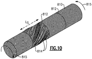
Figure 10 is a view similar to that shown inFigure 2A , but showing the effect of the disclosed embodiments. -
Figure 11A is yet another embodiment. -
Figure 11B is yet another embodiment. -
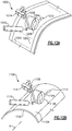
Figure 12A is a view of a manufacturing step. -
Figure 12B is a view of a manufacturing step. -
Figure 1 shows adrive arrangement 20, which drives acomponent 22 through adrive input 24. Adrive shaft 26 connects theinput 24 to theoutput 22. As one example,component 22 may be helicopter propellers. - The
drive shaft 26 may be formed of composite materials. Driveshafts 26 coming within the scope of this disclosure may be formed of fiber reinforced polymer matrix composite materials. In particular, the matrix can be a thermoplastic polymer. Different types of reinforcing fibers, such as, for example, carbon fibers, glass fibers, organic fibers, inorganic materials (e.g., ceramic) fibers, or their combinations can be used in different embodiments. In addition, while thermoplastic polymers are preferred, thermoset polymers may benefit from some of the structural details disclosed below. -
Figure 2A shows a concern with a knownshaft 26 during operation.Shaft 26 extends between ends 28a and 28b. There are "wrinkles" 28 that may be formed along the length of theshaft 26 due to local instability (buckling) from thetorque moment 29 transmitted through thedrive shaft 26. These wrinkles are shown inFigure 2A as an example of shear stress distribution, calculated by finite element method for a representative thin-walled composite drive shaft. -
Figure 2B illustrates a diametric cross-section in the center of a composite drive shaft shown inFigure 2A before and after the event of local buckling. As shown inFigure 2B , thewrinkles 28 can move theshaft 26 from its originalcylindrical shape 27 such that it has cross-sectional deformation at 28. -
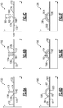
Figures 3-6 below show axial cross-sections of designs of composite drive shafts.Figure 3A shows knownshaft 26 having a uniform outer and inner surfaces. -
Figure 3B shows afirst embodiment 30 wherein the drive shaft has a nominalhollow tubular member 32 with aring member 34 adhered to the outer periphery. Themember ring 34 will resist the local buckling deformation under torsional moment, if bending stiffness of the ring member is sufficiently high. The bending stiffness of the ring member in the hoop direction is preferably, at least twice as high as the bending stiffness of a tubular member wall segment with the same width as the ring. -
Figure 3C shows anembodiment 31, which is similar toembodiment 30 except thering member 34 is between aninner wall 32 and anouter wall 36. A ramp or bump 38 is formed in theouter wall 36 to enclose thering member 34. -
Figure 3D shows yet anotherembodiment 39, similar toembodiment 31, but wherein there is anextra wrap 40 having abump 42 at the location of thebump 38. Thewrap 40 can minimize risk of debonding between thering member 34 andouter wall 36. Also, the wraps may help secure thering 34 to the underlyingtubular member 32. Further, the wraps can provide better adherence. In addition, by selecting materials for the wraps, any number of other features or characteristics can be placed into the tubes. -
Figure 3E shows anembodiment 43 similar to theembodiment 39, however,additional wraps wrap 40.Figure 3E illustrates a case with three wraps, however, different number of the wraps can be used according to specifics of designs, applications and load conditions. -
Figure 3F shows anembodiment 54 having anunderlying tubular member 32 withring members outer wrap 66 is placed outwardly ofring members ring member 62 is placed axiallyintermediate ring members wrap 66 and anouter wrap 68. Anotherwrap 70 is placed outwardly of thewrap 68. Similarly toFigure 3E , different number of wraps and unconnected individual rings can be used according to the specifics of requirements. -
Figure 4A shows anembodiment 70 wherein thering member 76 is on an inner surface 73 of thetubular member 72. Thetube 72 has an outwardly extendingbump 74 to accommodatering 76. -
Figure 4B shows anembodiment 80, which is similar toembodiment 70, however, anadditional wrap 82 is placed outward of thebump 74. -
Figure 4C shows an embodiment 84. Here,additional wraps embodiment 80. In other embodiments, different number of wraps can also be used. -
Figure 4D shows anembodiment 90. Here, tworing members 94 are axially spaced at a radially inner surface of aninner shaft 92. Anotherring member 100 is placed axiallyintermediate ring members 94, and radially intermediateinner shaft 92 and anouter shaft 102. Anotherwrap 104 is placed radially outward of thewrap 102. In other embodiments, different number of wraps and/or individual un-connected rings can also be used. -
Figure 5A shows anembodiment 110 whereinring members -
Figure 5B shows an embodiment 120 similar toFigure 3C , having anouter ring 122 outward of thering 126 and aninner ring 124. - The rings illustrated so far have been generally rectangular, or close to rectangular, in cross-section. Here "generally rectangular" shapes also include similar shapes with upper and lower surfaces of the ring parallel or almost parallel to each other with curved shapes at other side surfaces (e.g., corners at the left and right at
Figures 3-5 ). -
Figure 6A shows anembodiment 130 wherein thetube 132 has an L-shaped (in cross-section)ring member 134. L-shapedring member 134 is defined as having an axially extendingcontact portion 136, in contact with theouter periphery 133 of thetube 132. Radially outwardly extendingring 138 extends radially outwardly from theportion 136. An optional wrap 137 has aportion 140 secured to theouter surface 133 and aportion 142 radially outward of theportion 136 of thering 134. -
Figure 6B shows anembodiment 150 having a pair of L-shapedring members 134 having the radially outwardly extendingsurfaces 138 facing each other. Both can be provided withoptional wraps 139. -
Figure 6C shows an embodiment wherein thering member 162 has an I-shape (in cross-section) with a contactingportion 168 in contact with theouter periphery 133 of theinner shaft 132. A radially outwardly extendingportion 164 extends to a radially outwardthicker portion 166.Optional wraps 174 are secured on each axial end of theportion 164 and to thecontact portion 168. L- and I-shaped rings can have advantages in providing higher bending stiffness per weight in comparison, for example, with rings with rectangular cross-sections.Figure 6D shows aring 182 having anouter periphery 184 that has a part circular or similar curved convex shape in the cross-section. Acontact portion 183 is in contact with anouter surface 179 of thetube 181. An outeroptional wrap 186 is also secured atends 187 to theouter surface 179 and to thering 182. -
Figure 6E shows anembodiment 190 wherein thering member 192 has a pair ofdifferent material portions ring member 196 may be spaced on an opposed side of thetube 194 from thering 192. The materials may be selected to achieve particular benefits. -
Figure 6F shows anembodiment 200 wherein thetube 202 receives aring member 204 that has a hollow 206. The hollow 206 may also be filled by various materials, or may be left empty. Anoptional wrap 208 may also be secured outwardly of thering 204. -
Figure 7A shows theembodiments 220 such as has been illustrated to this point and having atubular member 222 with aring member 224 extending about the entire circumference. -
Figure 7B showsembodiment 230 wherein thetube 222 may receive aring member 224 extending across the entire circumference, but may also receiveisolated ring portions 232 extending between circumferential ends 234 extending through an angle A. In this embodiment, angle A may be 90°. Further, thering portions 232 may be utilized without thefull hoop ring 224 in some embodiments. -
Figure 7C shows anembodiment 330 wherein thetube 322 and the fullhoop ring member 324 receivering portions 332 extending between circumferential ends 334. Here, circumferential ends 334 extend through an angle B. In one embodiment, angle B is 60°. -
Figure 7D shows anembodiment 430 wherein thetubular member 422 has thering member 424 and thering portions 432.Ring portions 432 extend between ends 434.Ends 434 extend through a circumferential extent of an angle C. In embodiments, angle C is 45°. -
Figure 7E shows anembodiment 500 wherein atubular member 522 does not receive a full hoop ring. Rather, only the circumferentially spacedring portions 524 are utilized. While theembodiment 500 resemblesFigure 7D and its spacing, it should be understood that the other ring portions ofFigures 7B and 7C can be utilized without the underlying full hoop structure. The number and sizes of ring portions can be different in other embodiments and can be defined by design optimization driven, for example, by criteria of weight reduction. -
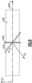
Figure 8 shows a feature with regard to atubular member 600 having acenter axis 606. Thering member 602 may be formed to be perpendicular relative to theaxis 606. On the other hand, aring 604 may extend at an angle such that it is not perpendicular to theaxis 606. The angle α here may be selected to provide various functions to optimize the drive shaft design for specific loading conditions. For example, one may account for bending and axial load components in addition to the torque. Angle α can be either uniform or non-uniform along the ring length. -
Figure 9A shows an example 700 whereintubular member 702 receives a plurality ofring members 704, which are all perpendicular to theaxis 708. -
Figure 9B shows anembodiment 710 wherein thetubular member 702 receives a plurality ofring members 712, which are all formed at a slope, such as shown in 604 inFigure 8 . -
Figure 9C shows anembodiment 730 wherein thetubular member 732 receivesring members 740 at a slope relative to theaxis 708 andother ring members 750 extending in an opposed angle relative to the angle α1 that thering members 740 are sloped relative toaxis 708. The angle α2 that thering members 750 are sloped with regard to theaxis 708 may be equal to, but in an opposed direction from the angle E. - At least one of the plurality of ring members could be said as having a central axis Zs which is non-perpendicular to a
central axis 708 of thetubular member 732. At least one of the central axis Zo of at least one of the plurality of ring members extends in an opposed direction relative to the central axis Zs of at least another of the plurality of the rings. -
Figure 9D shows anembodiment 750 wherein the underlyingtubular member 732 receives angledring members ring members 704. In addition, aring portion 760 is formed only at anend 761. -
Figure 9E shows anembodiment 780 wherein atubular member 781 hasring members Figure 9C or Figure 9D embodiments. However, thering members points 786. Opposite directions ofring members ring members - The ring members extending at a single slope, such as shown in
Figure 9B , might be especially helpful if torque is primarily applied in one direction. On the other hand, the embodiment ofFigure 9C may be helpful if there is rotation passing in both directions through the shaft. - With regard to the sloped ring members, it could be said that they extend at an angle relative to a central axis of the tubular member such that the outer peripheral surface of the ring members lies at different axial positions on an outer periphery of the tubular member measured along the
central axis 708. -
Figure 10 shows a feature of the disclosed shafts. Atubular member 810 hasring members 812 spaced along an axial dimension. There will still be deformation at 814 undertorque 815, such as the "wrinkle" mentioned with regard toFigure 2A . However, as can be appreciated, by shortening the length LS through which thedeformation 814 extends, the magnitude of the deformation will also be reduced. Here, the wrinkles are shown as distributions of shear stresses calculated by the finite element method for a problem similar to one shown atFigure 2 but with added rigid rings. -
Figure 11A shows afeature 900 wherein thetubular member 902 has a plurality of equally spacedring member 904. Thering member 904 inFigure 11A are spaced by an axial distance L1. -
Figure 11B shows anembodiment 910 wherein atubular member 912 receives ring members 914, 916, and 918. The ring members in theembodiment 910 are spaced by axial distances L2, L3, and L4. As can be appreciated, L2-L4 are not all the same length. - The lengths can be selected based upon an understanding that a buckling moment is approximately inversely proportional to the square root of the length L.
- A formula is shown below which will help select lengths L for a tube having a radius R.

- A method of attaching ring member using the Automated Fiber Placing (AFP) method is shown at 1000 in
Figure 12A . Atubular member 1002 is shown receiving amaterial 1004. Thematerial 1004 comes from a source, with a feed mechanism. Aconsolidation roller 1008 is rolling thematerial 1004 on an outerperipheral surface 1009. Aheater 1010 is providing heat to the material to cause it to deform and adhere to theouter surface 1009. Abeginning point 1012 of thematerial 1004 is shown. If a full ring is utilized, once the material 1006 reaches the end 1020, acutter 1014 cuts the material. Of course, in the embodiments having partial ring portions, the cutting would occur at the appropriate ends. -
Figure 12B shows anembodiment 1100 showing a method similar to that ofFigure 12A . Common features are indicated byreference numerals 100 larger than those shown inFigure 12A . However, the material 1104 is placed in an axial direction along an axis A of thetubular member 1102 or any other directions in addition to the axial and hoop directions. The embodiment shown inFigure 12B can be used to fabricate rings in non-circumferential directions (e.g., shown inFigures 9B-9E ) and/or to fabricate bodies of composite shafts with multi-directional laminated layups.. - The method shown in
Figure 12A and 12B is generally known as automated fiber placement (AFP) or automated tape laying (ATL). - A drive shaft according to this disclosure could be said to include a tubular member extending between axial ends and being hollow. The tubular member is formed of a thermoplastic matrix with embedded fibers. There is at least one ring member positioned radially of the tubular member.
- The "positioned radially" language should be understood to cover on an outer peripheral surface, an inner peripheral surface or at a radially intermediate location within the radial extend of the tubular member.
- The tubular member extends across 360°, and the ring member may also extend across 360°.
- Alternatively the tubular member may extend through 360° and the ring member extends through less than 360°. That is, the rings are formed of a plurality of spaced ring portions, such that the ring does not extend across 360°.
- A wrap may be placed on an opposed side of the ring member relative to the at least one of the inner and outer peripheral surfaces.
- There may also be a plurality of the ring member, with one ring member placed on the outer peripheral surface and a second of the ring members placed on an inner peripheral surface.
- There may be a plurality of ring members spaced along an axial length of the tubular member. An axial distance along a central axis of the tubular member is defined between each of the plurality of rings. The axial distance may be uniform across an axial length of the tubular member. Alternatively, an axial distance between adjacent ones of the rings along an axial length of the tubular member may be non-uniform.
- The ring member may be at least part circular in cross-section. Alternatively, the ring member may be non-circular in cross-section. The ring member may be a part circular cross-section.
- A method of forming a drive shaft could be said to include the steps of forming a tubular member extending along an axis, and having an inner peripheral surface and an outer peripheral surface. Further, the method includes the steps of forming at least one ring member by placing a material on one of the inner peripheral surface and outer peripheral surface, and heating the material. Radial pressure is applied to the material in a sequentially moved fashion. The material is adhered to the one of inner and outer peripheral surface.
- A method of forming a drive shaft could also be said as providing the steps of forming a tubular member extending along an axis, and having an inner peripheral surface and an outer peripheral surface. A ring portion in this format on at least one of the inner and outer peripheral surfaces by placing a material on the at least one of the inner and outer peripheral surfaces, applying a roller to the material to adhere the material to the at least one of the inner and outer peripheral surfaces while applying heat to the material.
- While the automated fiber placement is the preferred method, various other methods may be utilized. As an example, when the tubular member is a composite, the composite tube could be formed as a continuous element or assembly of segments. The rings may be formed separate from the tube, rather than being formed on the tube. The additional wraps may be attached utilizing automated fiber placement about the rings or can be attached by other methods.
- The ring member and tubular member can be secured together by solidifying when the thermoplastic is utilized for both the tube and the rings. In addition, welding can be utilized if thermoplastic is utilized for both the tube and the rings. If a thermoset is used, the ring can be cured onto the tube. Further, the materials can be pre-cured or partially-cured. In addition, radial fasteners, glue or any combination of the various attachment methods disclosed above may be utilized.
- It could also be said that this disclosure provides a drive shaft with a tubular member extending between axial ends and being hollow. The tubular member is formed of a thermoplastic matrix with embedded fibers. There is a ring on the tubular member. The ring may be on an outer peripheral portion as shown in some Figures, on an inner peripheral portion, as shown in other Figures, or intermediate the inner and outer peripheral portions, shown in yet other Figures. Further, there may be a plurality of rings.
- To the extent these teachings extend to a drive shaft with a metallic tubular member, the metallic tubular member could be formed of a continuous element or an assembly of segments. The ring member can be formed separately. The rings can be assembled with the tube and the rings with or without extra wraps. Welding can be utilized if the ring is also metallic. If the rings are thermoplastic, they can be solidified onto the tubular member. If the ring is thermoset, it can be cured, pre-cured, or partially cured and then placed onto the metallic tubular member. Again, radial fasteners, adhesives, or any combination of the above may be utilized.
- It should be understood across these embodiments that the wraps are optional and the ring may stand alone. The rings can be formed of a composite and the wraps may be formed of a composite. Alternatively, the rings may be metallic or the wraps may be formed of a metallic material. In addition, while composite shaft are the main focus of this disclosure, many of the structural combinations disclosed here would benefit metallic shafts. Any combination of composite and material shafts/rings/wraps may come within the scope of this disclosure.
- Several embodiments are disclosed above. A worker of ordinary skill in this art would recognize that certain modifications would come within the scope of this disclosure. For that reason, the following claims should be studied to determine the true scope of the invention.
Claims (15)
- A drive shaft comprising:a tubular member (32) extending between axial ends and being hollow, said tubular member formed of a thermoplastic matrix with embedded fibers; andat least one ring member (34) positioned radially of said tubular member.
- The drive shaft as set forth in claim 1, wherein said tubular member extends across 360° in the circumferential direction, and said ring member also extends across 360° in the circumferential direction.
- The drive shaft as set forth in claim 1, wherein said tubular member extends across 360° in the circumferential direction and said ring member includes a plurality of spaced ring portions, such that said ring member does not extend across 360° in the circumferential direction.
- The drive shaft as set forth in any preceding claim, wherein a wrap is placed on an opposed side of said ring member relative to said at least one of an inner and outer peripheral surface of said tubular member.
- The drive shaft as set forth in any preceding claim, wherein there are a pair of said ring members (60,64), with one of said pair of said ring members placed on an outer peripheral surface of said tubular member and a second of said rings placed on an inner peripheral surface of said tubular member.
- The drive shaft as set forth in any of claims 1 to 4, wherein there are a plurality of ring members (86, 88), with at least one of the plurality of ring members placed within a radial extent of said tubular member, and others of said plurality of ring members being placed on at least one of an inner peripheral surface and an outer peripheral surface of said tubular member.
- The drive shaft as set forth in any of claims 1 to 4, wherein there are a plurality of ring members (94) spaced along an axial length of said tubular member, and an axial distance along a central axis of said tubular member is defined between each of said plurality of ring members and said axial distance is uniform across an axial length of said tubular member.
- The drive shaft as set forth in any of claims 1 to 4, wherein there are a plurality of ring members spaced along an axial length of said tubular member, and an axial distance is defined along a control axis of said tubular member between adjacent ones of said ring members and said axial distances are not uniform.
- The drive shaft as set forth in any preceding claim, wherein said ring member is generally rectangular in cross-section, or wherein said ring member is non-circular in cross-section or wherein said ring member has a part circular cross-section, or wherein said ring member has one of a generally L-shape in cross-section or a generally I-shape in cross-section.
- The drive shaft as set forth in any preceding claim, wherein said ring member is formed of either of a thermoplastic matrix with embedded fibers or a metal material or their combination, or wherein said ring member is formed of a material other than a thermoplastic or a metal.
- The drive shaft as set forth in any preceding claim, wherein said ring member is centered about an axis which is parallel to a central axis of said tubular member, or wherein said ring member is centered on an axis which is non-parallel to a central axis of said tubular member.
- The drive shaft as set forth in any of claims 1 to 4 or any claim dependent thereon, wherein there is a plurality of said ring members each having a central axis which is non-parallel to said central axis of said tubular member, and at least one said central axis of at least one of said plurality of ring members extending in an opposed direction relative to said central axis of at least another of said plurality of said ring members.
- A method of forming a drive shaft providing steps of:forming a tubular member extending along an axis, and having an inner peripheral surface and an outer peripheral surface;forming at least one ring member by placing a material on one of said inner peripheral surface and said outer peripheral surface;heating the material;applying radial pressure to the material in a sequentially moved fashion; andadhering the material to said one of inner and outer peripheral surface.
- The method as set forth in claim 18, wherein said ring member is formed for 360° in a circumferential direction about a central axis of said tubular member.
- The method as set forth in claim 14, wherein said ring member includes a plurality of ring portions and each of said ring portions extending for less than 360° in a circumferential direction about a central axis of said tubular member.
Applications Claiming Priority (1)
| Application Number | Priority Date | Filing Date | Title |
|---|---|---|---|
| US16/655,722 US11859665B2 (en) | 2019-10-17 | 2019-10-17 | Drive shafts made of composite materials and methods of making such shafts |
Publications (1)
| Publication Number | Publication Date |
|---|---|
| EP3809003A1 true EP3809003A1 (en) | 2021-04-21 |
Family
ID=68917632
Family Applications (1)
| Application Number | Title | Priority Date | Filing Date |
|---|---|---|---|
| EP19216567.8A Pending EP3809003A1 (en) | 2019-10-17 | 2019-12-16 | Drive shafts made of composite materials and methods of making such shafts |
Country Status (2)
| Country | Link |
|---|---|
| US (3) | US11859665B2 (en) |
| EP (1) | EP3809003A1 (en) |
Cited By (3)
| Publication number | Priority date | Publication date | Assignee | Title |
|---|---|---|---|---|
| EP4155559A1 (en) * | 2021-09-24 | 2023-03-29 | Goodrich Corporation | Drive shafts |
| EP4345326A1 (en) * | 2022-09-30 | 2024-04-03 | Goodrich Corporation | Flexible composite drive shaft |
| US12631208B2 (en) | 2023-02-07 | 2026-05-19 | Goodrich Corporation | Flexible composite drive shaft |
Citations (6)
| Publication number | Priority date | Publication date | Assignee | Title |
|---|---|---|---|---|
| CA1162408A (en) * | 1980-08-25 | 1984-02-21 | Alan J. Hannibal | Flexible coupling |
| US4838833A (en) * | 1986-08-15 | 1989-06-13 | A. O. Smith Corporation | Fiber reinforced resin drive shaft having improved resistance to torsional buckling |
| US20160281767A1 (en) * | 2015-03-26 | 2016-09-29 | Showa Corporation | Vehicle propeller shaft |
| US20190003522A1 (en) * | 2017-06-30 | 2019-01-03 | Crompton Technology Group Limited | Strut comprising composite cylinder with a mid-strut fitting |
| EP3683461A1 (en) * | 2019-01-15 | 2020-07-22 | Hamilton Sundstrand Corporation | Drive shafts with enhanced bending flexibility |
| EP3683462A2 (en) * | 2019-01-15 | 2020-07-22 | Goodrich Corporation | Composite shaft with outer periphery ring |
Family Cites Families (17)
| Publication number | Priority date | Publication date | Assignee | Title |
|---|---|---|---|---|
| US4248062A (en) | 1979-10-05 | 1981-02-03 | Shakespeare Company | Drive shaft assembly and method for making same |
| US4695340A (en) | 1985-09-30 | 1987-09-22 | United Technologies Corporation | Filament wound structure having filament wound reinforcing rings for use as a torque drive |
| US4895551A (en) | 1987-09-24 | 1990-01-23 | A. O. Smith Corporation | Dynamically balanced drive shaft |
| JPH01229110A (en) | 1988-02-24 | 1989-09-12 | A O Smith Corp | Fiber-reinforced resin driving shaft |
| SE502460C2 (en) | 1993-06-04 | 1995-10-23 | Bofors Ab | Methods and apparatus for temperature-independent storage |
| US6210283B1 (en) | 1998-10-30 | 2001-04-03 | General Electric Company | Composite drive shaft |
| EP1303722B1 (en) | 2000-06-16 | 2007-09-26 | Vyatek Sports, Inc. | High performance composite tubular structures |
| JP3771514B2 (en) * | 2002-04-19 | 2006-04-26 | 本田技研工業株式会社 | Shaft structure of portable power work machine |
| GB2406154B (en) | 2003-09-17 | 2007-01-03 | Crompton Technology Group Ltd | Hybrid composite transmission shaft |
| FR2869074B1 (en) | 2004-04-14 | 2006-07-21 | Snecma Moteurs Sa | MAIN SHAFT PROTECTION ARRANGEMENT OF FUSE BEARING MOTOR |
| US7472736B2 (en) * | 2005-02-14 | 2009-01-06 | The Boeing Company | Modular head lamination device and method |
| EP2412995B1 (en) | 2010-07-30 | 2012-12-12 | Eurocopter Deutschland GmbH | Drive train |
| US8984940B2 (en) | 2012-04-04 | 2015-03-24 | Elliot Company | Passive dynamic inertial rotor balance system for turbomachinery |
| US9387378B2 (en) | 2012-05-29 | 2016-07-12 | Mitsubishi Rayon Co., Ltd. | Golf club shaft for wood club |
| WO2014058463A1 (en) | 2012-10-09 | 2014-04-17 | United Technologies Corporation | Geared turbofan engine with inter-shaft deflection feature |
| GB201508021D0 (en) | 2015-05-11 | 2015-06-24 | Sigma Composites Ltd | Fibre reinforced polymer matrix composite torque tubes or shafts |
| EP3480479B1 (en) | 2017-11-01 | 2024-10-30 | Crompton Technology Group Limited | Transmission shaft |
-
2019
- 2019-10-17 US US16/655,722 patent/US11859665B2/en active Active
- 2019-12-16 EP EP19216567.8A patent/EP3809003A1/en active Pending
-
2022
- 2022-12-02 US US18/074,209 patent/US20230119039A1/en not_active Abandoned
-
2025
- 2025-09-19 US US19/333,988 patent/US20260016045A1/en active Pending
Patent Citations (6)
| Publication number | Priority date | Publication date | Assignee | Title |
|---|---|---|---|---|
| CA1162408A (en) * | 1980-08-25 | 1984-02-21 | Alan J. Hannibal | Flexible coupling |
| US4838833A (en) * | 1986-08-15 | 1989-06-13 | A. O. Smith Corporation | Fiber reinforced resin drive shaft having improved resistance to torsional buckling |
| US20160281767A1 (en) * | 2015-03-26 | 2016-09-29 | Showa Corporation | Vehicle propeller shaft |
| US20190003522A1 (en) * | 2017-06-30 | 2019-01-03 | Crompton Technology Group Limited | Strut comprising composite cylinder with a mid-strut fitting |
| EP3683461A1 (en) * | 2019-01-15 | 2020-07-22 | Hamilton Sundstrand Corporation | Drive shafts with enhanced bending flexibility |
| EP3683462A2 (en) * | 2019-01-15 | 2020-07-22 | Goodrich Corporation | Composite shaft with outer periphery ring |
Cited By (4)
| Publication number | Priority date | Publication date | Assignee | Title |
|---|---|---|---|---|
| EP4155559A1 (en) * | 2021-09-24 | 2023-03-29 | Goodrich Corporation | Drive shafts |
| US12123458B2 (en) | 2021-09-24 | 2024-10-22 | Goodrich Corporation | Drive shafts |
| EP4345326A1 (en) * | 2022-09-30 | 2024-04-03 | Goodrich Corporation | Flexible composite drive shaft |
| US12631208B2 (en) | 2023-02-07 | 2026-05-19 | Goodrich Corporation | Flexible composite drive shaft |
Also Published As
| Publication number | Publication date |
|---|---|
| US20210115965A1 (en) | 2021-04-22 |
| US11859665B2 (en) | 2024-01-02 |
| US20260016045A1 (en) | 2026-01-15 |
| US20230119039A1 (en) | 2023-04-20 |
Similar Documents
| Publication | Publication Date | Title |
|---|---|---|
| US20260016045A1 (en) | Drive shafts made of composite materials and methods of making such shafts | |
| EP3162544B1 (en) | Method and device for producing contoured composite laminate stiffeners with reduced wrinkling | |
| EP3954912B1 (en) | Composite shaft with outer periphery ring | |
| EP3081822A1 (en) | Hybrid metal-composite drive shaft unit and method of manufacturing the same | |
| EP3486503B1 (en) | Designs and methods of making of joints for composite components under dominant bending load | |
| US10527086B2 (en) | Strut comprising composite cylinder with a mid-strut fitting | |
| GB2051303A (en) | Fibre-reinforced composite shaft with metallic connector sleeves | |
| US3881973A (en) | Joint construction and method of fabrication | |
| US7861411B2 (en) | Composite gear and method of forming same | |
| US20200132109A1 (en) | Composite drive shafts | |
| EP3202557B1 (en) | Strut comprising composite cylinder with a mid-strut fitting | |
| EP4033114A1 (en) | Buckling-resistant thin-wall drive shafts | |
| US20240369096A1 (en) | Integrated composite drive shafts | |
| JPH05106629A (en) | Fiber-reinforced plastic load transmission shaft | |
| EP3680093B1 (en) | Hybrid metallic/composite structural component for torque, bending, shear, and axial loading and method for its manufacture | |
| EP4345326A1 (en) | Flexible composite drive shaft | |
| US12467499B2 (en) | Drive shaft with non-cylindrical shape and spaced reinforcements | |
| US12577977B2 (en) | Integrated composite drive shafts | |
| US12631208B2 (en) | Flexible composite drive shaft | |
| EP3508336B1 (en) | Hybrid metallic/composite axial tension/compression lobe joint | |
| WO2020109766A1 (en) | Attachment of an end fitting to a composite material tube |
Legal Events
| Date | Code | Title | Description |
|---|---|---|---|
| PUAI | Public reference made under article 153(3) epc to a published international application that has entered the european phase |
Free format text: ORIGINAL CODE: 0009012 |
|
| STAA | Information on the status of an ep patent application or granted ep patent |
Free format text: STATUS: THE APPLICATION HAS BEEN PUBLISHED |
|
| AK | Designated contracting states |
Kind code of ref document: A1 Designated state(s): AL AT BE BG CH CY CZ DE DK EE ES FI FR GB GR HR HU IE IS IT LI LT LU LV MC MK MT NL NO PL PT RO RS SE SI SK SM TR |
|
| AX | Request for extension of the european patent |
Extension state: BA ME |
|
| STAA | Information on the status of an ep patent application or granted ep patent |
Free format text: STATUS: REQUEST FOR EXAMINATION WAS MADE |
|
| 17P | Request for examination filed |
Effective date: 20211021 |
|
| RBV | Designated contracting states (corrected) |
Designated state(s): AL AT BE BG CH CY CZ DE DK EE ES FI FR GB GR HR HU IE IS IT LI LT LU LV MC MK MT NL NO PL PT RO RS SE SI SK SM TR |
|
| STAA | Information on the status of an ep patent application or granted ep patent |
Free format text: STATUS: EXAMINATION IS IN PROGRESS |
|
| 17Q | First examination report despatched |
Effective date: 20220519 |